ADC Telecommunications FWM1901B FlexWave™ microBTS 1900 MHz 2X1 User Manual 75246
ADC Telecommunications Inc FlexWave™ microBTS 1900 MHz 2X1 75246
User manual
FlexWave™ Base Station System
2x1 microBTS
Installation Manual
ADCP-75-246 • Issue 1 • 6/2008
1431641 Rev A
22576-A

ADCP-75-246 • Issue 1 • 6/2008 • Preface
Page ii
COPYRIGHT
© 2008, ADC Telecommunications, Inc.
All Rights Reserved
REVISION HISTORY
LIST OF CHANGES
The technical changes incorporated into this issue are listed below.
TRADEMARK INFORMATION
ADC and ADC Telecommunications are registered trademarks of ADC Telecommunications, Inc.
FlexWave is a trademark of ADC Telecommunications, Inc.
nanoBTS is a trademark of ip.access Ltd.
TORX is a trademark of Textron, Inc.
DISCLAIMER OF LIABILITY
Contents herein are current as of the date of publication. ADC reserves the right to change the contents without prior notice. In no
event shall ADC be liable for any damages resulting from loss of data, loss of use, or loss of profits and ADC further
disclaims any and all liability for indirect, incidental, special, consequential or other similar damages. This disclaimer of
liability applies to all products, publications and services during and after the warranty period.
This publication may be verified at any time by contacting ADC’s Technical Assistance Center at 1-800-366-3891, extension 73475
(in U.S.A. or Canada) or 952-917-3475 (outside U.S.A. and Canada), or by e-mail to connectivity_tac@adc.com.
ISSUE DATE REASON FOR CHANGE
1 06/2008 Original release
PAGE IDENTIFIER DESCRIPTION OF CHANGE
- Original release
ADC Telecommunications, Inc.
P.O. Box 1101, Minneapolis, Minnesota 55440-1101
In U.S.A. and Canada: 1-800-366-3891
Outside U.S.A. and Canada: (952) 938-8080
Fax: (952) 917-1717

ADCP-75-246 • Issue 1 • 6/2008 • Preface
Page iii
© 2008, ADC Telecommunications, Inc.
TABLE OF CONTENTS
Content Page
ABOUT THIS MANUAL . . . . . . . . . . . . . . . . . . . . . . . . . . . . . . . . . . . . . . . . . . . . . . . . . . . . . . . . . . . . . . . . . . . . . . . . . v
RELATED PUBLICATIONS . . . . . . . . . . . . . . . . . . . . . . . . . . . . . . . . . . . . . . . . . . . . . . . . . . . . . . . . . . . . . . . . . . . . . . . v
ADMONISHMENTS . . . . . . . . . . . . . . . . . . . . . . . . . . . . . . . . . . . . . . . . . . . . . . . . . . . . . . . . . . . . . . . . . . . . . . . . . . . v
GENERAL SAFETY PRECAUTIONS . . . . . . . . . . . . . . . . . . . . . . . . . . . . . . . . . . . . . . . . . . . . . . . . . . . . . . . . . . . . . . . . .vi
STANDARDS CERTIFICATION . . . . . . . . . . . . . . . . . . . . . . . . . . . . . . . . . . . . . . . . . . . . . . . . . . . . . . . . . . . . . . . . . . . .vi
LIST OF ACRONYMS AND ABBREVIATIONS . . . . . . . . . . . . . . . . . . . . . . . . . . . . . . . . . . . . . . . . . . . . . . . . . . . . . . . . . . vii
1 INTRODUCTION. . . . . . . . . . . . . . . . . . . . . . . . . . . . . . . . . . . . . . . . . . . . . . . . . . . . . . . . . . . . . . . . . . . . . . . . . 1
2 MICR0BTS DESCRIPTION . . . . . . . . . . . . . . . . . . . . . . . . . . . . . . . . . . . . . . . . . . . . . . . . . . . . . . . . . . . . . . . . . . 1
2.1 Primary Components . . . . . . . . . . . . . . . . . . . . . . . . . . . . . . . . . . . . . . . . . . . . . . . . . . . . . . . . . . . . . . . 2
2.2 Mounting . . . . . . . . . . . . . . . . . . . . . . . . . . . . . . . . . . . . . . . . . . . . . . . . . . . . . . . . . . . . . . . . . . . . . . . 2
2.3 Fault Detection and Alarm Reporting . . . . . . . . . . . . . . . . . . . . . . . . . . . . . . . . . . . . . . . . . . . . . . . . . . . . 2
2.4 IP Backhaul Connection . . . . . . . . . . . . . . . . . . . . . . . . . . . . . . . . . . . . . . . . . . . . . . . . . . . . . . . . . . . . . 2
2.5 Network Listen Antenna Connection . . . . . . . . . . . . . . . . . . . . . . . . . . . . . . . . . . . . . . . . . . . . . . . . . . . . . 2
2.6 Base Station Antenna Cable Connection . . . . . . . . . . . . . . . . . . . . . . . . . . . . . . . . . . . . . . . . . . . . . . . . . . 3
2.7 Powering . . . . . . . . . . . . . . . . . . . . . . . . . . . . . . . . . . . . . . . . . . . . . . . . . . . . . . . . . . . . . . . . . . . . . . . 3
2.8 Grounding . . . . . . . . . . . . . . . . . . . . . . . . . . . . . . . . . . . . . . . . . . . . . . . . . . . . . . . . . . . . . . . . . . . . . . 3
2.9 Cooling . . . . . . . . . . . . . . . . . . . . . . . . . . . . . . . . . . . . . . . . . . . . . . . . . . . . . . . . . . . . . . . . . . . . . . . . 3
2.10 User Interface . . . . . . . . . . . . . . . . . . . . . . . . . . . . . . . . . . . . . . . . . . . . . . . . . . . . . . . . . . . . . . . . . . . . 3
2.11 Specifications . . . . . . . . . . . . . . . . . . . . . . . . . . . . . . . . . . . . . . . . . . . . . . . . . . . . . . . . . . . . . . . . . . . . 5
3 ACCESSORY ITEMS . . . . . . . . . . . . . . . . . . . . . . . . . . . . . . . . . . . . . . . . . . . . . . . . . . . . . . . . . . . . . . . . . . . . . . 6
3.1 Strand Mount Kit . . . . . . . . . . . . . . . . . . . . . . . . . . . . . . . . . . . . . . . . . . . . . . . . . . . . . . . . . . . . . . . . . . 6
3.2 Lightning Protector . . . . . . . . . . . . . . . . . . . . . . . . . . . . . . . . . . . . . . . . . . . . . . . . . . . . . . . . . . . . . . . . 6
3.3 Solar Shields . . . . . . . . . . . . . . . . . . . . . . . . . . . . . . . . . . . . . . . . . . . . . . . . . . . . . . . . . . . . . . . . . . . . 6
4 UNPACKING AND INSPECTION . . . . . . . . . . . . . . . . . . . . . . . . . . . . . . . . . . . . . . . . . . . . . . . . . . . . . . . . . . . . . . 7
5 MOUNTING PROCEDURES . . . . . . . . . . . . . . . . . . . . . . . . . . . . . . . . . . . . . . . . . . . . . . . . . . . . . . . . . . . . . . . . . 8
5.1 Before Mounting the microBTS . . . . . . . . . . . . . . . . . . . . . . . . . . . . . . . . . . . . . . . . . . . . . . . . . . . . . . . . 8
5.2 Lift Ring Installation . . . . . . . . . . . . . . . . . . . . . . . . . . . . . . . . . . . . . . . . . . . . . . . . . . . . . . . . . . . . . . 11
5.3 Standard Mounting Bracket Installation . . . . . . . . . . . . . . . . . . . . . . . . . . . . . . . . . . . . . . . . . . . . . . . . . 11
5.4 Installing the Enclosure on the Standard Mounting Bracket . . . . . . . . . . . . . . . . . . . . . . . . . . . . . . . . . . . . 16
5.5 Strand-Mount Installation . . . . . . . . . . . . . . . . . . . . . . . . . . . . . . . . . . . . . . . . . . . . . . . . . . . . . . . . . . . 17
6 INSTALLATION PROCEDURES . . . . . . . . . . . . . . . . . . . . . . . . . . . . . . . . . . . . . . . . . . . . . . . . . . . . . . . . . . . . . . 18
6.1 Installation Overview . . . . . . . . . . . . . . . . . . . . . . . . . . . . . . . . . . . . . . . . . . . . . . . . . . . . . . . . . . . . . . 18
6.2 Ground Wire Installation. . . . . . . . . . . . . . . . . . . . . . . . . . . . . . . . . . . . . . . . . . . . . . . . . . . . . . . . . . . . 19
6.3 Network Listen Antenna Installation . . . . . . . . . . . . . . . . . . . . . . . . . . . . . . . . . . . . . . . . . . . . . . . . . . . . 20
6.4 IP Backhaul Cable Installation. . . . . . . . . . . . . . . . . . . . . . . . . . . . . . . . . . . . . . . . . . . . . . . . . . . . . . . . 21
6.5 Base Station Antenna Cable Installation . . . . . . . . . . . . . . . . . . . . . . . . . . . . . . . . . . . . . . . . . . . . . . . . . 22
6.6 AC Power Wiring Installation. . . . . . . . . . . . . . . . . . . . . . . . . . . . . . . . . . . . . . . . . . . . . . . . . . . . . . . . . 23
6.7 Touch-Up Painting . . . . . . . . . . . . . . . . . . . . . . . . . . . . . . . . . . . . . . . . . . . . . . . . . . . . . . . . . . . . . . . . 25
6.8 Power-Up and Testing . . . . . . . . . . . . . . . . . . . . . . . . . . . . . . . . . . . . . . . . . . . . . . . . . . . . . . . . . . . . . 25
6.9 microBTS Replacement . . . . . . . . . . . . . . . . . . . . . . . . . . . . . . . . . . . . . . . . . . . . . . . . . . . . . . . . . . . . 26
7 CUSTOMER INFORMATION AND ASSISTANCE . . . . . . . . . . . . . . . . . . . . . . . . . . . . . . . . . . . . . . . . . . . . . . . . . . . 27

ADCP-75-246 • Issue 1 • 6/2008 • Preface
Page iv
© 2008, ADC Telecommunications, Inc.
TABLE OF CONTENTS
Content Page
Blank

ADCP-75-246 • Issue 1 • 6/2008 • Preface
Page v
© 2008, ADC Telecommunications, Inc.
ABOUT THIS MANUAL
This publication provides a description of the FlexWave microBTS (Base Transceiver Station).
Also provided are procedures for mounting and installing the microBTS. An overview of the
FlexWave Base Station System (BSS), a description of the system components, the system turn-
up and test procedures, and the system troubleshooting procedures are provided in other
publications. The microBTS works in conjunction with the Base Station Controller (BSC).
RELATED PUBLICATIONS
Listed below are related manuals and their publication numbers. Copies of these publications
can be ordered by contacting the ADC Technical Assistance Center at 1-800-366-3891,
extension 73476 (in U.S.A. or Canada) or 1-952-917-3476 (outside U.S.A. and Canada).
ADC FlexWave BSS List of User Documentation 75-330
ADC FlexWave V3.1 BSS Overview 75-329
ADC FlexWave Base Station System Provisioning Guide 75-312
ADC FlexWave V3.1 Base Station System Configuration Guide 75-321
ADC FlexWave V3.1 BSS MIB Definitions 75-319
ADC FlexWave BSS nanoBTS OMC-R User Manual 75-331
ADC FlexWave SR3.1 BSS LCT Operations Guide 75-306
ADC FlexWave BSS BSC Configuration Utilities Guide 75-316
ADMONISHMENTS
Important safety admonishments are used throughout this manual to warn of possible hazards to
persons or equipment. An admonishment identifies a possible hazard and then explains what
may happen if the hazard is not avoided. The admonishments — in the form of Dangers,
Warnings, and Cautions — must be followed at all times. These warnings are flagged by use of
the triangular alert icon (seen below) and are listed in descending order of severity of injury or
damage and likelihood of occurrence.
Title ADCP Number
Danger: Danger is used to indicate the presence of a hazard that will cause severe personal
injury, death, or substantial property damage if the hazard is not avoided.
Warning: Warning is used to indicate the presence of a hazard that can cause severe personal
injury, death, or substantial property damage if the hazard is not avoided.
Caution: Caution is used to indicate the presence of a hazard that will or can cause minor
personal injury or property damage if the hazard is not avoided.

ADCP-75-246 • Issue 1 • 6/2008 • Preface
Page vi
© 2008, ADC Telecommunications, Inc.
GENERAL SAFETY PRECAUTIONS
STANDARDS CERTIFICATION
1900 MHz microBTS Standards
FCC: The microBTS complies with the applicable sections of Title 47 CFR Part 24.
Caution: Modifications not expressly approved by the party responsible for compliance
could void the user’s authority to operate the equipment.
Note: To comply with Maximum Permissible Exposure (MPE) requirements, the maximum
composite output from the antenna cannot exceed 1640 Watts EIRP and the antenna must be
permanently installed in a fixed location that provides at least 6 meters (20 feet) of separation
from all persons.
UL/CUL: The microBTS complies with NEMA Type 6, UL and CUL 50 Standard for
Enclosures for Electrical Equipment.
The microBTS provides the degree of protection specified by IP67 as defined in IEC
(International Electrotechnical Commission) Publication 60529.
This microBTS complies with UL and CUL 60950 and UL 50 as Communication Service
Equipment under the DUZO category.
IC: The microBTS complies with the applicable sections of RSS-133. The term “IC:” before the
radio certification number only signifies that Industry Canada Technical Specifications were met.
1800 MHz microBTS Standards
EU Harmonized Standards: Meets essential requirements of R&TTE 1999/5/EC.
• Article 3.1a – The protection of the health and the safety of the user and any other person,
including the objectives with respect to safety requirements contained in Directive 72/23/
EEC, but with no voltage limit applying.
• Article 3.1b – The protection requirements with respect to electromagnetic compatibility
contained in Directive 89/336/EEC.
• Article 3.2 – In addition, radio equipment shall be so constructed that it effectively uses
the spectrum allocated to terrestrial/space radio communication and orbital resources so as
to avoid harmful interference.
Warning: Wet conditions increase the potential for receiving an electrical shock when
installing or using electrically-powered equipment. To prevent electrical shock, never install or
use electrical equipment in a wet location or during a lightning storm.

ADCP-75-246 • Issue 1 • 6/2008 • Preface
Page vii
© 2008, ADC Telecommunications, Inc.
LIST OF ACRONYMS AND ABBREVIATIONS
The acronyms and abbreviations used in this manual are detailed in the following list:
AC Alternating Current
AMR Adaptive Multi-Rate
AW G American Wire Gauge
BSC Base Station Controller
BSS Base Station System
BTS Base Transceiver Station
CCelsius
CUL Canadian Underwriters Laboratories
DC Direct Current
EDGE Enhanced Data rates for GSM Evolution
EMS Element Management System
ESD Electrostatic Discharge
EU European Union
FFahrenheit
FCC Federal Communications Commission
GFCI Ground Fault Circuit Interrupter
GPRS General Packet Radio Service
GSM Global System for Mobile communications
IEC International Electrotechnical Commission
IC Industry Canada
IP Internet Protocol
LED Light Emitting Diode
LNA Low Noise Amplifier
LPA Linear Power Amplifier
MHz Megahertz
MPE Maximum Permissible Exposure
MTBF Mean Time Between Failure
NEM Network Element Manager
NEMA National Electrical Manufacturers Association
OMC-R Operations and Maintenance Center - Radio
OSP Outside Plant
POE Power Over Ethernet
RF Radio Frequency
RMA Return Material Authorization
RX Receive or Receiver
TAC Technical Assistance Center
TRX Transmit/Receive
UL Underwriters Laboratories
VA Volt Amps

ADCP-75-246 • Issue 1 • 6/2008 • Preface
Page viii
© 2008, ADC Telecommunications, Inc.
VAC Volts Alternating Current
VDC Volts Direct Current
ADCP-75-246 • Issue 1 • 6/2008
Page 1
© 2008, ADC Telecommunications, Inc.
1 INTRODUCTION
The FlexWave 2x1 microBTS is an environmentally hardened outdoor base station solution that
supports GSM/AMR voice traffic and GPRS/EDGE data traffic. An Internet Protocol (IP)
backhaul provides the interface between the microBTS and the Base Station Controller (BSC).
All voice and data traffic and all operation and maintenance functions are transported by the IP
backhaul. A complete FlexWave Operations and Maintenance Center - Radio (OMC-R)
management solution is available that provides total control of the microBTS, BSC, and other
FlexWave system elements.
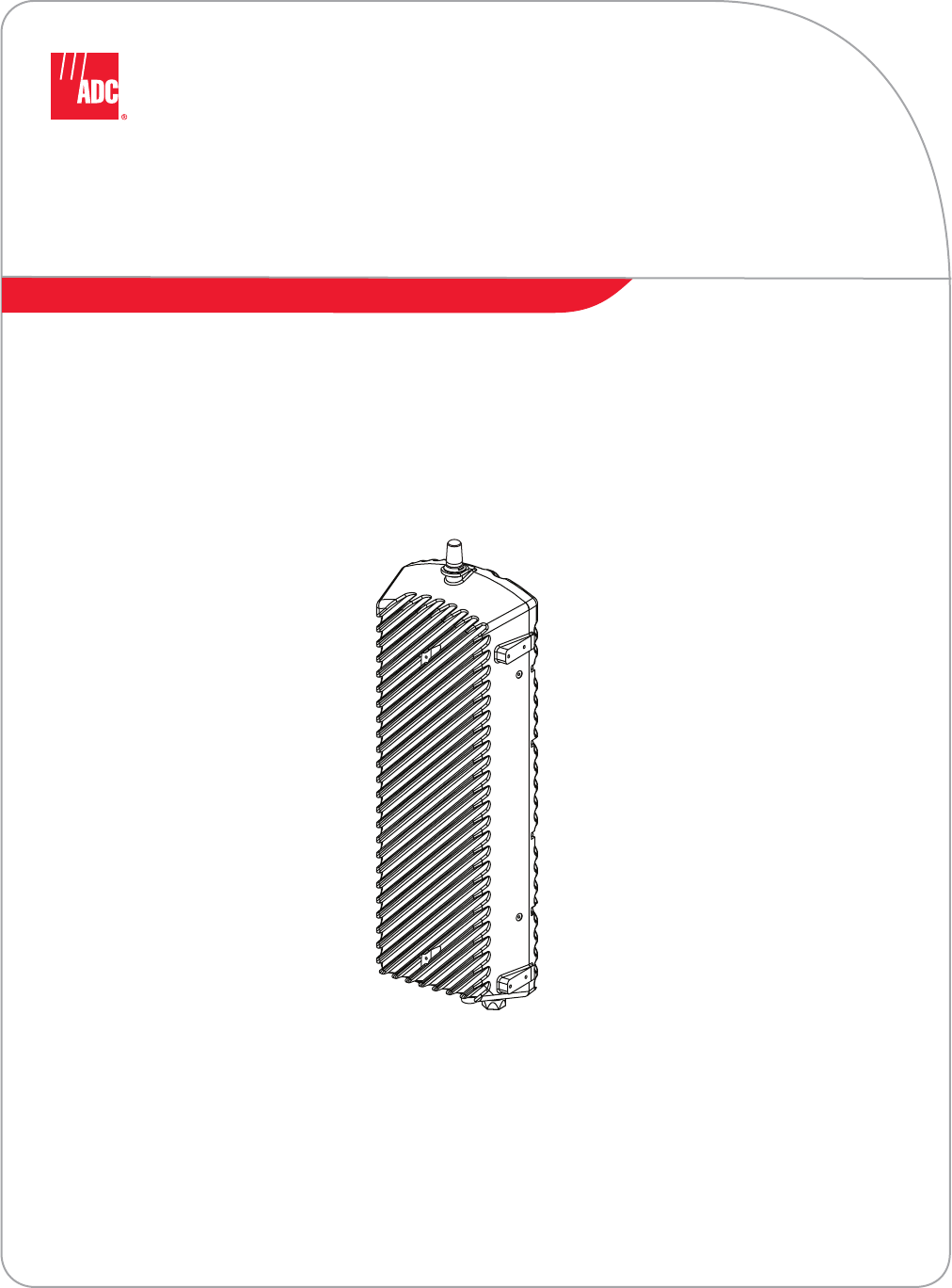
The microBTS, shown in Figure 1, consists of an environmentally-sealed enclosure and various
electronic modules that are housed within the enclosure. Excess heat is dissipated using a
passive cooling system which eliminates the need for external cooling fans. The low profile
design of the enclosure requires minimal real estate for installation. The enclosure may be
mounted from a wall, pole, or overhead cable (strand). A separate base station antenna (not
provided) mounts near the enclosure.
Figure 1. 2x1microBTS
2 MICROBTS DESCRIPTION
The 2x1 microBTS, supports or provides the following basic functions:
• Supports GSM/AMR voice traffic and GPRS/EDGE data traffic via two TRX units.
• Supports OMC-R functions including provisioning, alarm management, and performance
management.
• Supports IP backhaul for voice and data traffic and OMC-R communications.
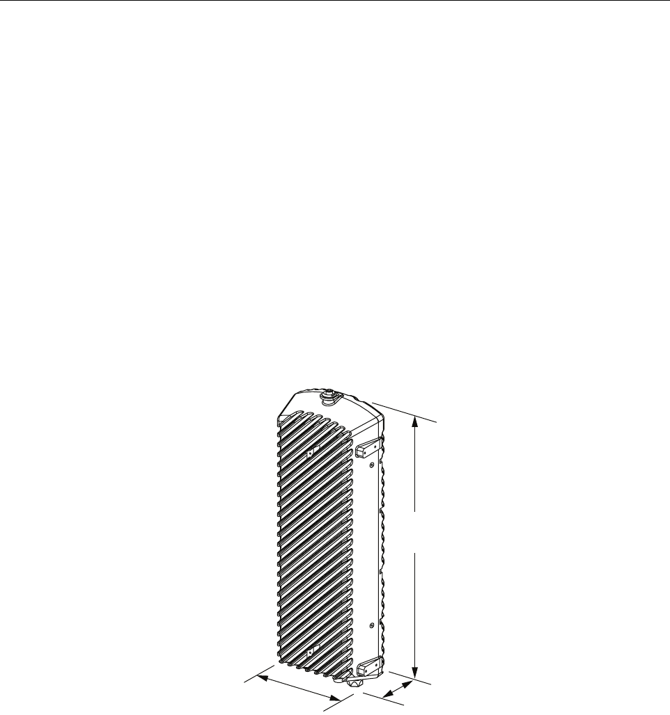
29.4 IN.
(74.7 CM)
5.7 IN.
(14.5 CM)
9.7 IN.
(24.6 CM) 22577-A

ADCP-75-246 • Issue 1 • 6/2008
Page 2
© 2008, ADC Telecommunications, Inc.
• Provides Power Over Ethernet (POE) to the IP backhaul device
• Provides an RF interface (antenna port) for the base station remote antenna.
• Provides an RF interface (antenna port) for the Network Listen antenna.
• Accepts AC power input.
• Provides a visual indication of unit status
2.1 Primary Components
The microBTS is a fully integrated base station solution that includes the following: radio
transceivers (2), Linear Power Amplifier (LPA), RX Low Noise Amplifier (LNA), duplexer,
power supply, IP switches, Network Listen unit, processor board, carrier board, and enclosure.
The enclosure houses the electronic assemblies, controls RF emissions, seals out dirt and
moisture, and provides passive cooling. The internal components are not user replaceable or
accessible. The base station antenna cable connector, IP backhaul connector, AC power
connector, and the unit status indicator are located on the bottom of the enclosure. The Network
Listen antenna connector is located on the top of the enclosure.
2.2 Mounting
The microBTS may be mounted on a flat vertical surface (such as the side of a building), on a
utility pole, or from a strand. A combination wall/pole mounting bracket is provided with each
unit. Wall or pole-mount installation consists of securing the bracket to the mounting surface
and then hanging the enclosure from the bracket. The bracket may be attached to a variety of
surfaces such as wood, concrete, or masonry. Various fasteners including hex-head capscrews,
tee-nuts, and concrete anchors are provided. A separate strand-mount kit (accessory item) is
available if it is necessary to mount the microBTS from a cable. The mircroBTS should be
mounted in a restricted access location only.
2.3 Fault Detection and Alarm Reporting
The microBTS detects and reports fault and alarm information. A single bottom-mounted Light
Emitting Diode (LED) indicator turns from off to red if a major fault is detected. The status of
the microBTS, the alarm state, and other fault information is summarized and reported over the
IP backhaul. Fault and alarm information may be accessed using the FlexWave OMC-R
management solution.
2.4 IP Backhaul Connection
The IP backhaul cable connection is through an Ethernet port that consists of a single bottom-
mounted hardened RJ-45 female connector. The IP backhaul cable carries the voice and data
traffic plus all OMC-R provisioning, alarm, and performance monitoring communications
between the microBTS and the BSC. The IP backhaul connection also provides DC power
(POE) to the IP backhaul device with a 15 Watt maximum power output at 48 VDC. The
maximum drop cable length is 300 feet (91.4 m).
2.5 Network Listen Antenna Connection
The Network Listen antenna (depending on the option ordered) connection is through a single
top-mounted NMO (female) RF connector. The Network Listen antenna attaches directly to the
NMO connector.

ADCP-75-246 • Issue 1 • 6/2008
Page 3
© 2008, ADC Telecommunications, Inc.
2.6 Base Station Antenna Cable Connection
The base station antenna cable connection is through one 50-ohm N-type female connector. The
microBTS includes an internal duplexer which allows a single antenna cable to carry both
forward and reverse path RF signals between the base station antenna and the microBTS.
An externally-mounted lightning protector is available as an accessory. The surge/antenna
connector on the lightning protector is an N-type female connector. The microBTS enclosure
must be properly grounded for the lighting protector to function properly.
2.7 Powering
The microBTS is powered by 90 to 265 VAC (nominal 115 or 230 VAC), 47 to 63 Hz power.
The AC power is supplied through a 15-foot three-wire power cable that is provided with the
enclosure. The power cable connects to a mini 3-pin AC power connector mounted on the
bottom of the microBTS enclosure. The power cable is rated for indoor or outdoor use and must
not be placed within electrical conduit as this will impede the cooling of the cable during usage.
The stub end of the power cable must be routed to an external junction box (not provided) for
connection to the AC power source. A circuit breaker rated at 15 Amps (150 VAC) should be
used to provide overcurrent protection for the microBTS power circuit. It is also recommended
that an external AC outlet (not provided) be installed near the microBTS enclosure to power test
equipment and power tools.
2.8 Grounding
A grounding terminal (hex socket capscrew and washer) is provided on the bottom of the
enclosure for connecting a grounding cable to the enclosure. A 1.5 meter #6 stranded copper
wire terminated with a ring terminal is provided with the microBTS for linking the enclosure to
an earth ground source.
2.9 Cooling
Passive cooling of the electronic assemblies is provided by conducting excess heat from the
internal electronic components to the aluminum enclosure. The heat is then dissipated to the
outside air by radiation and convection air flow over the enclosure’s external cooling fins. An
alarm is generated if a high temperature condition occurs within the enclosure.
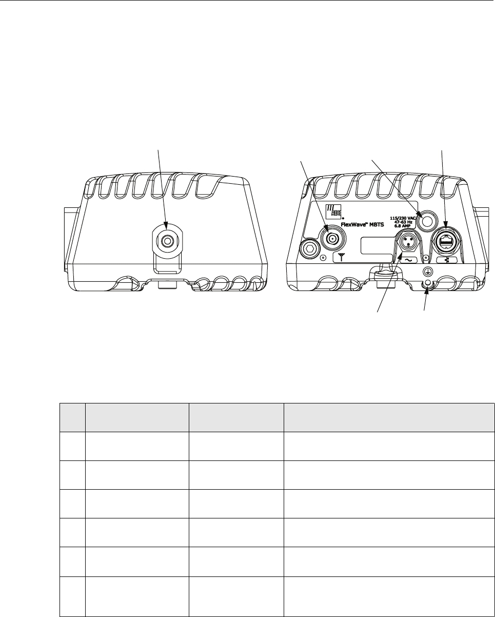
2.10 User Interface
The microBTS user interface consists of the connectors, grounding lug, and LED that are
provided on the exterior of the enclosure. The microBTS user interface points are indicated in
Figure 2 and described in Table 1.
ADCP-75-246 • Issue 1 • 6/2008
Page 4
© 2008, ADC Telecommunications, Inc.
Figure 2. 2x1 microBTS User Interface
Table 1. 2x1 microBTS User Interface
REF
NO
USER INTERFACE
DESIGNATION DEVICE FUNCTIONAL
DESCRIPTION
1 No designation NMO female RF
connector
Connection point for the Network Listen
antenna.
2 Ground symbol Threaded hole with
hex socket screw
Connection point for the grounding wire.
3 Antenna symbol N-type female RF
coaxial connector
Connection point for the base station antenna
cable.
4 Network symbol Sealed RJ-45 female
connector
Connection point for the IP backhaul cable.
5 No designation Red LED
(off/red)
Indicates if the microBTS is powered and normal
(off) or if a major fault is detected (red).
6 115/230 VAC
47–63 Hz
6.8 AMP
Sealed 3-wire AC
power connector
Connection point for the AC power cord.
22589-A
(5) LED
INDICATOR
TOP VIEW BOTTOM VIEW
(1) NETWORK LISTEN
ANTENNA CONNECTOR
(4) IP BACKHAUL
CABLE CONNECTOR
(2) GROUNDING WIRE
CONNECTION POINT
(6) AC POWER
CONNECTOR
NOTE: SHOWN WITH DUST CAPS REMOVED
(3) BASE STATION
ANTENNA
CONNECTOR

ADCP-75-246 • Issue 1 • 6/2008
Page 5
© 2008, ADC Telecommunications, Inc.
2.11 Specifications
The specifications for the 2x1 microBTS are listed in Table 2.
Table 2. 2x1 microBTS Specifications
PARAMETER SPECIFICATION REMARKS
Physical/Environmental/
Electrical
Enclosure dimensions (L×W×D) 29.4 × 9.7 × 5.7 inches
(747 × 246 × 145 mm)
0.94 cu. ft.
(26.6 L)
Mounting Wall, pole, or strand Strand mounting requires an
accessory mounting kit.
Weight 40 lbs (18.2 kg) Without shields installed
Weather resistance (see Note 1) NEMA-6, IEC IP67 Indoor or outdoor installation
Operating temperature –30º to +55º C (-22º to +131º F)
Storage temperature –40º to +70º C (-40º to +158º F)
AC power connector Sealed 3-pin AC power
Antenna cable connector 50 ohm N-type (female) 50 ohms input/output impedance
IP backhaul connector Sealed RJ-45 (female) Ethernet port
Power over Ethernet port 48 VDC with 15 Watt maximum
Network Listen antenna connec-
tor
NMO (female)
Lightning suppression (for
antenna cable connector)
20 kA IEC 1000-4-5 8/20 μs
waveform
Provided by external lightning
protector (accessory)
Voltage input 90 to 265 VAC, 47 to 63 Hz
Power consumption (maximum) 600 VA at 120 VAC
Current rating (maximum) 6.8 Amps at 90 VAC Requires 15 Amp circuit for 115
VAC operation
Downlink
System bandwidth 60 MHz
Frequency range for 1800 MHz 1805 – 1880 MHz
Frequency range for 1900 MHz 1930 – 1990 MHz
Out-of-band emissions < –13 dBm per 1 MHz band-
width from 30 MHz to 20 GHz
Passband gain 21 dB In addition to +13 dBm gain set-
ting on each nanoBTS
Composite RF output power
(maximum)
41.5 dBm (14.13 Watts) max at
antenna port
40.5 dBm (11.22 Watts) for
Industry Canada using two-tone
method
Gain variation ± 3 dB over temperature and
unit-to-unit

ADCP-75-246 • Issue 1 • 6/2008
Page 6
© 2008, ADC Telecommunications, Inc.
Note 1: The microBTS has been tested to assure it meets the dust and water resistance
requirements of IP67 as specified by IEC Publication 60529. These tests were conducted using
closure caps attached to the cable ports. To assure the dust and water resistance level is
maintained, it is the responsibility of the user to select AC power, antenna, and IP backhaul
cable assemblies that have a dust and water resistance level of IP67 or higher. If user is uncertain
of cable manufacturers that meet this requirement, please contact ADC Technical Assistance.
3 ACCESSORY ITEMS
This section provides a description of the accessory items that are available separately for the
microBTS. The accessory items may or may not be required depending on the application.
3.1 Strand Mount Kit
A strand-mount kit is available if the application requires that the microBTS be mounted from a
horizontal cable system. Mounting pads are provided on the side of the enclosure for securing a
pair of cable-attachment clips. Screws are used to secure the cable-attachment clips to the
enclosure. All fasteners required for installation are provided with the kit.
3.2 Lightning Protector
An external lightning protector is available separately for the microBTS. It is recommended that
a lightning protector be installed at the base station antenna port to reduce the chance of damage
to electronic components should a lightning strike occur. The lighting protector surge/antenna
port is an N-type female connector.
3.3 Solar Shields
A solar shield kit is available if the microBTS must be mounted in full sunlight for extended
periods of time with extremely high ambient temperatures. The solar shields attach to the
exterior of the microBTS enclosure and shade the enclosure from direct exposure to the sun.
The solar shields are constructed of sheet metal and are painted to match the color of the
enclosure. All fasteners and brackets required for installation are provided with the kit.
Gain flatness
Band flatness
Channel flatness
± 1.5 dB across frequency range
± 1.0 dB across any 1.25 MHz
channel
Uplink
Frequency range for 1800 MHz 1710 – 1785 MHz
Frequency range for 1900 MHz 1850 – 1910 MHz
RX sensitivity (CS-1 M) <-110 dB
RX sensitivity (MCS-1M) < -110 dB
RX sensitivity (MCS-5 M) < -102 dB
Table 2. 2x1 microBTS Specifications, continued
PARAMETER SPECIFICATION REMARKS

ADCP-75-246 • Issue 1 • 6/2008
Page 7
© 2008, ADC Telecommunications, Inc.
4 UNPACKING AND INSPECTION
This section provides instructions for opening the shipping boxes, verifying that all parts have
been received, and verifying that no shipping damage has occurred. The basic microBTS
includes the following items:
• microBTS enclosure
• Network Listen antenna
• Fasteners, cables, strapping, and mounting bracket as specified in Table 3, Section 5, and
Table 4, Section 6.
The following accessories may also be shipped with the microBTS:
• Strand mount kit
• Lightning protector
•Shields
Use the following procedure to unpack and inspect the microBTS components:
1. Open the shipping cartons and carefully unpack each component from the protective
packing material.
2. Check each component for broken or missing parts. If there are damages, contact ADC
(see Section 7) for an RMA (Return Material Authorization) and to reorder if replacement
is required.

ADCP-75-246 • Issue 1 • 6/2008
Page 8
© 2008, ADC Telecommunications, Inc.
5 MOUNTING PROCEDURES
This section provides instructions for mounting the FlexWave microBTS. The microBTS may
be secured to an interior or exterior wall, attached to a utility pole, or attached to a horizontal
cable (strand-mount). Mounting the microBTS from a cable requires an accessory kit not
included with the unit.
5.1 Before Mounting the microBTS
5.1.1 Mounting Considerations
Before mounting the microBTS, verify that the installation site is in conformance with the
system design plan (not documented here). If a system design plan has not been prepared,
consult the Wireless Technical Assistance Center (TAC) for technical assistance (see Section 7).
The site chosen must conform to all local codes and any permits required must be obtained prior
to the start of mounting. The location must be accessible and provide adequate parking for
worker and vehicle safety. The installed unit must not create a visual or physical obstruction to
vehicular or pedestrian traffic or block pole-climbing access.
The microBTS must be located as specified in the system design plan and must have ready
access to the specified AC power source. The site must provide adequate ventilation and must
comply with the unit environmental specifications. A minimum of 18 inches of clearance must
be provided on all sides (except the back) of the enclosure to allow free air circulation. In
addition, the bottom (cable entry end) and either the top, the front, or one of the sides must be
open to free air space. Adequate clearance must be allowed at the bottom of the enclosure to
provide access for attaching cables and for viewing the LED indicator.
5.1.2 Mounting Hardware Provided With the microBTS
The microBTS is shipped with the mounting hardware required for a typical wall-mount or
pole-mount installation. Table 3 lists the mounting hardware provided. Additional hardware
may have to be provided by the installer depending on the site requirements.
Note: The microBTS is intended for restricted access locations only.
Table 3. microBTS Mounting Hardware and Fasteners
ITEM QUANTITY
Hoist ring 1
Hoist ring mounting screws 2
Mounting bracket 1
Strapping 2
3/8-inch concrete anchors 4
3/8 x 1-inch cap screws 4
3/8 x 1.5-inch lag screws 4
ADCP-75-246 • Issue 1 • 6/2008
Page 9
© 2008, ADC Telecommunications, Inc.
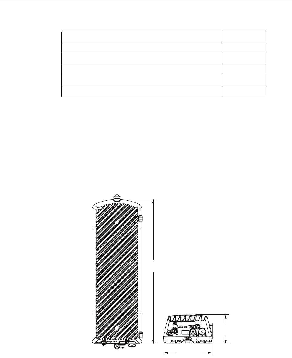
5.1.3 2x1 microBTS Dimensions
The basic dimensions of the 2x1 microBTS are shown in Figure 3.
Figure 3. 2x1 microBTS Dimensions
3/8-inch flat washers 4
3/8-inch lock washers 4
5/16 x1.25-inch cap screw 1
5/16-inch flat washer 1
5/16-inch lock washer 1
5/16-inch nut 1
Table 3. microBTS Mounting Hardware and Fasteners, continued
22636-A
9.7 IN.
(24.6 CM)
5.7 IN.
(14.5 CM)
29.4 IN.
(74.7 CM)

ADCP-75-246 • Issue 1 • 6/2008
Page 10
© 2008, ADC Telecommunications, Inc.
5.1.4 Tools and Additional Materials Required For Mounting
The tools and any additional materials required for mounting the 2x1 microBTS are dependent
on the mounting system. The following sections list the tools required for the various mounting
systems.
Wood-Framed Wall Mounting
• 9/16-inch wrench
• 1/2-inch wrench (2)
• Torque wrench with 3/16-inch hex key socket
• Drill
• Pencil or marker
• 4 foot x 2 foot sheet of pressure-treated 3/4-inch plywood
• Fasteners and tools for securing the 3/4-inch plywood to wall
• 3/16-inch standard drill bit
Masonry Wall Mounting
• 9/16-inch wrench
• 1/2-inch wrench (2)
• Torque wrench with 3/16-inch hex key socket
• Drill
• Pencil or marker
• 5/8-inch masonry drill bit
Wooden Utility Pole Mounting
• 9/16-inch wrench
• 1/2-inch wrench (2)
• Torque wrench with 3/16-inch hex key socket
• Drill
• Pencil or marker
• 3/16-inch standard drill bit
Metal Utility Pole Mounting
• Clamp banding tool (BT1HT from Panduit)
• 1/2-inch wrench (2)
• Torque wrench with 3/16-inch hex key socket
ADCP-75-246 • Issue 1 • 6/2008
Page 11
© 2008, ADC Telecommunications, Inc.
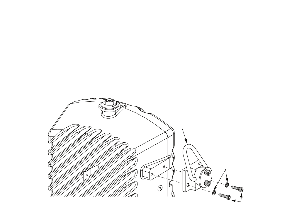
5.2 Lift Ring Installation
A lift ring is provided with the microBTS. Secure the lift ring to the side of the enclosure as
shown in Figure 4 using the two 5/8-inch long 1/4-20 socket head screws and two 1/4-inch split
washers provided. Use a torque wrench with a 3/16-inch hex key socket to tighten the cap screws
to 40 – 45 lbs/force-inches (4.5 to 5.1 Nm) of torque. Do not overtighten. If the threads show
signs of damage, yielding, or stripping when tightening the cap screws, discontinue lift ring
installation and remove the lift ring. Always use appropriate lifting equipment when hoisting the
enclosure into position for mounting. Remove the lift ring after the enclosure has been mounted.
Figure 4. Hoist Ring Installation
5.3 Standard Mounting Bracket Installation
A standard mounting bracket is provided with each enclosure. The standard mounting bracket
may be mounted vertically or horizontally. If mounted horizontally, it is recommended that the
bracket be oriented so the enclosure cooling fins will face upward or to the side with respect to
the ground. The following sections provide instructions for installing the standard mounting
bracket on a wood-framed wall, masonry wall, wooden utility pole, or metal pole. Refer to the
procedure that applies to the installation.
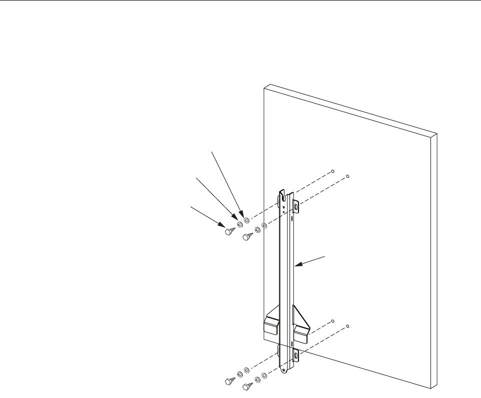
5.3.1 Wood-Framed Wall Mounting
When mounting the enclosure on a wood-framed wall, it is recommended that pressure-treated
plywood with a minimum thickness of 0.75-inch (19.0 cm) be used as a backer board. The
backer must be firmly secured to the interior framing of the wall. Use the following procedure to
install the standard mounting bracket on a wood-framed wall:
1. Mount the plywood backer (not-provided) on the wall and firmly secure it to the wall’s
interior studs.
2. Hold the enclosure mounting bracket in position for installation on the plywood backer as
shown in Figure 5. The end with the V-notch should be at the top.
22637-A
5/8-INCH LONG
1/4-20 CAP SCREWS
USE A TORQUE WRENCH
WITH A 3/16-INCH HEX KEY TO
TIGHTEN THE CAP SCREWS TO
40 TO 45 LBS/FORCE-INCHES
(4.5 TO 5.1 Nm) OF TORQUE
NOTE: IF THE THREADS SHOW SIGNS OF DAMAGE, YIELDING, OR STRIPPING
WHEN THE CAP SCREWS ARE TIGHTENED, DISCONTINUE INSTALLATION OF
THE LIFT RING. REMOVE LIFT RING AND DO NOT USE TO LIFT microBTS.
LIFT
RING
SPLIT
WASHERS
ADCP-75-246 • Issue 1 • 6/2008
Page 12
© 2008, ADC Telecommunications, Inc.
Figure 5. Secure Standard Mounting Bracket To Plywood Backer
3. Mark the location of the mounting bracket’s two mounting holes on the plywood backer.
4. Drill a 3/16-inch hole in the backer board at each of the locations marked in step 3.
5. Locate the two 3/8 x 1-1/2-inch lag screws (provided with the enclosure) and place a 3/8-
inch lock washer and 3/8-inch flat washer on each screw.
6. Secure the mounting bracket to the plywood using the screws and washers prepared in step
5. Tighten screws until bracket is securely attached to the plywood.
7. Hang the enclosure from the mounting bracket as described in Section 5.4.
2263-A
3/8 x 1-1/2-INCH
LAG SCREW (2)
3/8-INCH FLAT
WASHER (2)
3/4-INCH PLYWOOD
BACKER BOARD
(SECURE TO WALL STUDS)
3/8-INCH LOCK
WASHER (2)
MOUNTING
BRACKET
NOTE: THE MOUNTING BRACKET IS
SHOWN WITH A VERTICAL ORIENTATION.
THE MOUNTING BRACKET MAY ALSO
BE MOUNTED HORIZONTALLY IF REQUIRED.
ADCP-75-246 • Issue 1 • 6/2008
Page 13
© 2008, ADC Telecommunications, Inc.
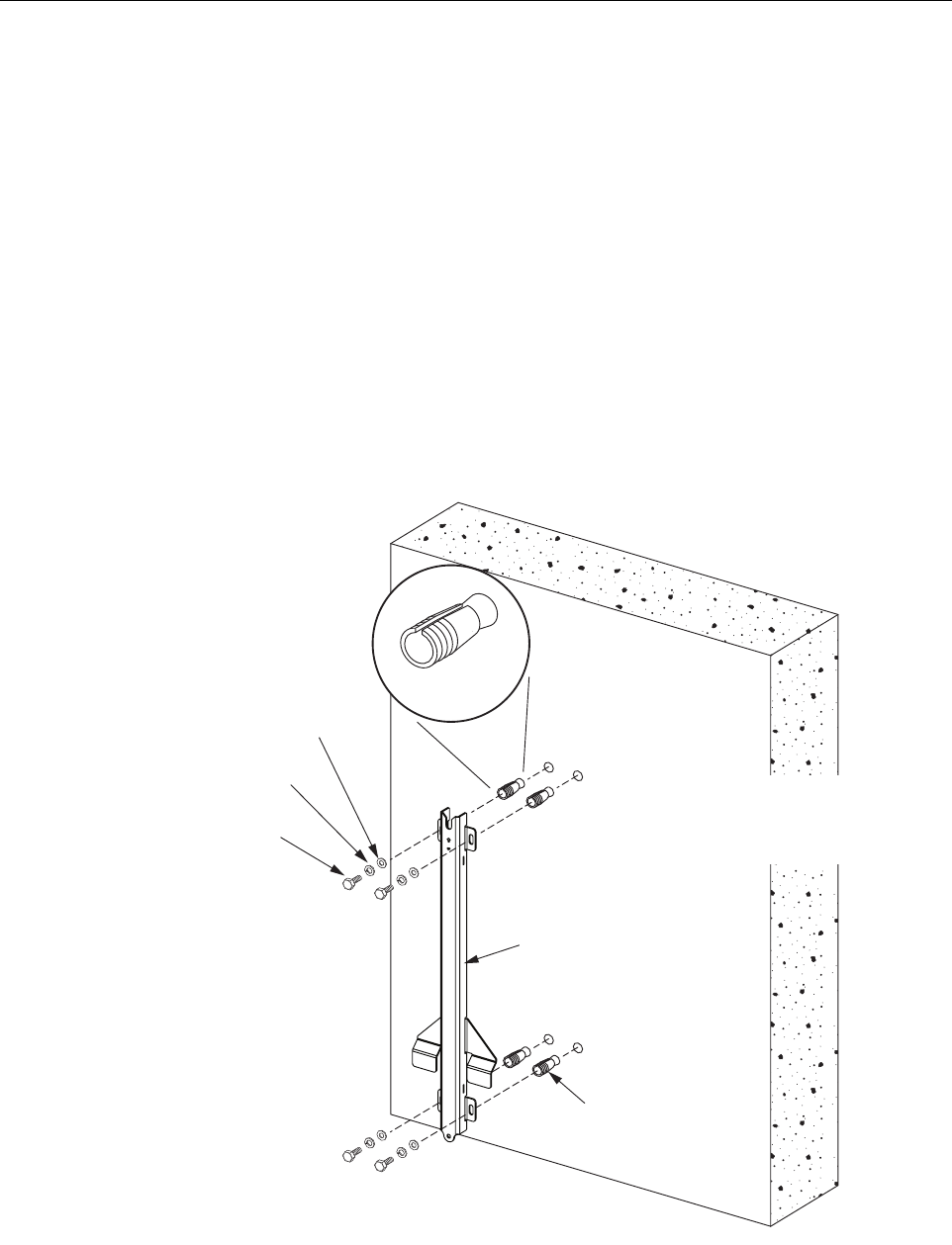
5.3.2 Masonry Wall Mounting
When mounting the enclosure on a masonry surface, locate the mounting anchors as close as
possible to the center of any bricks or blocks, especially the upper anchors. Use the following
procedure to install the standard mounting bracket on a masonry wall:
1. Hold the enclosure mounting bracket in position for installation on the masonry wall as
shown in Figure 6. The end with the V-notch should be at the top.
2. Using a pencil, mark the location of the mounting bracket’s two mounting holes on the
wall.
3. Drill holes in the wall (at the locations marked in step 2) that are the correct diameter for
the type of anchors being used. The recommended hole size for the ADC-provided
concrete anchors is 5/8-inch (15.9 mm).
4. Set the anchors in the wall.
Figure 6. Secure Standard Mounting Bracket to a Masonry Wall
22633-A
3/8-INCH
CONCRETE
ANCHOR (2)
CONCRETE
WALL
MOUNTING
BRACKET
NOTE: THE MOUNTING BRACKET IS
SHOWN WITH A VERTICAL ORIENTATION.
THE MOUNTING BRACKET MAY ALSO
BE MOUNTED HORIZONTALLY IF REQUIRED.
3/8 x 1-INCH
HEX BOLT (2)
3/8-INCH FLAT
WASHER (2)
3/8-INCH LOCK
WASHER (2)
CONCRETE
ANCHOR
ADCP-75-246 • Issue 1 • 6/2008
Page 14
© 2008, ADC Telecommunications, Inc.
5. Locate the two 3/8 x 1-inch cap screws (provided with enclosure) and place a 3/8-inch
lock washer and 3/8-inch flat washer on each screw.
6. Place the mounting bracket in position for mounting on the wall and then thread the 3/8 x
1-inch cap screws (with installed washers) into the two anchors. Tighten cap screws until
secure.
7. Hang the enclosure from the mounting bracket as shown in Section 5.4.
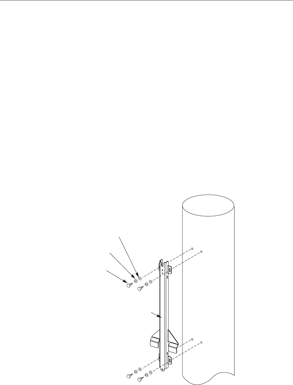
5.3.3 Wooden Utility Pole Mounting
When mounting the enclosure from a wooden utility pole, make sure the pole is sound and has
not been damaged or weakened by decay. Use the following procedure to install the standard
mounting bracket on a wooden utility pole:
1. Hold the enclosure mounting bracket in position for installation on the wooden pole as
shown in Figure 7. The end with the V-notch should be at the top.
2. Using a pencil, mark the location of the mounting bracket’s two mounting holes on the
pole.
3. Mark the location of the mounting bracket’s two mounting holes on the wooden pole.
Figure 7. Secure Standard Mounting Bracket to a Wooden Pole
22634-A
MOUNTING
BRACKET
3/8 x 1-1/2-INCH
LAG SCREW (4)
3/8-INCH FLAT
WASHER (4)
3/8-INCH LOCK
WASHER (4)
ADCP-75-246 • Issue 1 • 6/2008
Page 15
© 2008, ADC Telecommunications, Inc.
4. Drill a 3/16-inch hole in the utility pole at each of the locations marked in step 3.
5. Locate the two 3/8 x 1-1/2-inch lag screws (provided with the enclosure) and place a 3/8-
inch lock washer and 3/8-inch flat washer on each screw.
6. Secure the mounting bracket to the pole using the screws and washers prepared in step 5.
Tighten screws until bracket is securely attached to the plywood.
7. Hang the enclosure from the mounting bracket as shown in Section 5.4.
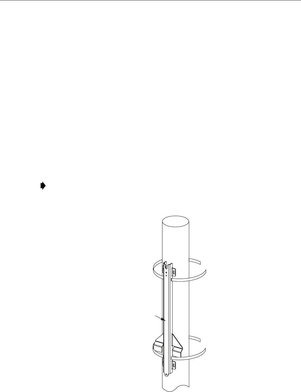
5.3.4 Metal Utility Pole Mounting
Stainless steel strapping is provided for securing the mounting bracket to a cylindrical object
(such as a metal utility pole) that cannot be pierced with a screw or bolt. A special tool (Panduit
BT1HT) is required to properly secure and tension the strapping. Use the following procedure
to install the mounting bracket on a metal utility pole:
1. Insert the two sections of stainless steel metal strapping (provided with the enclosure)
through the slots in the mounting bracket and place in position for mounting as shown in
Figure 8. The end with the V-notch should be at the top.
Figure 8. Secure Standard Mounting Bracket To a Metal Pole
Note: Two sections of stainless steel metal strapping are provided with the enclosure. If
additional strapping is required, use 5/8-inch wide 304 AISI stainless steel strapping with
a minimum tensile strength of 700 lbs force.
22635-A
MOUNTING
BRACKET
ADCP-75-246 • Issue 1 • 6/2008
Page 16
© 2008, ADC Telecommunications, Inc.
2. Wrap the top section of strapping around the pole and secure using Panduit tool # BT1HT.
Adjust the tool tension setting to #7. Follow the instructions provided with the tool by the
tool manufacturer (see MS Strapping Tool Operation Instructions PA24808A01).
3. Repeat step 2 for the bottom section of strapping.
4. Hang the enclosure from the mounting bracket as shown in Section 5.4.
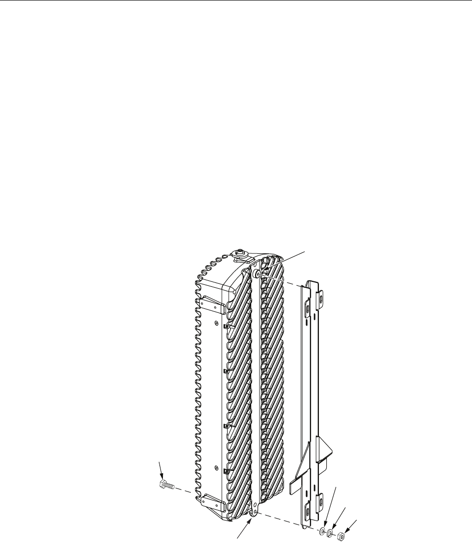
5.4 Installing the Enclosure on the Standard Mounting Bracket
Use the following procedure to install the microBTS on the standard mounting bracket.
1. Hang the enclosure from the mounting bracket as shown in Figure 9. The shoulder screw
in the rear side of the enclosure fits into the notch at the top of the mounting bracket.
Figure 9. Secure Enclosure To Mounting Bracket
2. Insert a 5/16 x 1-1/4-inch hex bolt through the hole in the mounting tab located at the
bottom of the enclosure.
3. Place a 5/16-inch flat washer and 5/16-inch flat washer on the hex bolt.
4. Thread a 5/16-inch nut onto the hex bolt and tighten securely.
5/16 x 1-1/4-INCH
HEX BOLT
5/16 INCH NUT
5/16 INCH
LOCK WASHER
5/16 INCH
FLAT WASHER
22632-A
MOUNTING TAB
SHOULDER
SCREW

ADCP-75-246 • Issue 1 • 6/2008
Page 17
© 2008, ADC Telecommunications, Inc.
5.5 Strand-Mount Installation
An accessory kit is available for mounting the microBTS enclosure from an overhead wire or
strand. The strand-mount kit can accommodate wire cable that ranges in size from 0.25 to 0.625
inches in diameter. A minimum break strength of 4400 lbs. is recommended. Stainless steel
cable is preferred.
An installation drawing is provided with each strand-mount kit. Follow the instructions
provided on the drawing when installing the strand-mount kit. For all strand-mount
installations, form a drip-loop in the cables entering the enclosure.

ADCP-75-246 • Issue 1 • 6/2008
Page 18
© 2008, ADC Telecommunications, Inc.
6 INSTALLATION PROCEDURES
This section provides procedures for installing the Network Listen antenna; connecting the
grounding, base station antenna, IP backhaul, and AC power cables; and installing the shields.
Installation of the microBTS may proceed separately from the installation of the corresponding
BSC. When the installation of the microBTS is completed, refer to the appropriate manuals (see
Related Publications section) for the system turn-up and test procedures.
6.1 Installation Overview
Installation of the microBTS consists of the following basic steps:
1. Connecting a grounding cable to the microBTS grounding point.
2. Installing the Network Listen antenna.
3. Connecting the IP backhaul cable.
4. Connecting the base station antenna coaxial cable to the microBTS antenna port.
5. Installing the AC power cable and connecting it to the microBTS power port.
6. Installing the shields.
6.1.1 Installation Hardware Provided with microBTS Enclosure
The installation hardware that is provided with the microBTS is listed in Table 4.
Danger: Wet conditions increase the potential for receiving an electrical shock when installing
or using electrically-powered equipment. To prevent electrical shock, never install or use
electrical equipment in a wet location or during a lightning storm.
Note: To insure that all connectors and ports remain dust-free during installation,
leave all dust caps and dust protectors in place until directed to remove them.
Note: If the microBTS will be horizontally mounted, provide drip loops for all cables that
connect to the enclosure.
Table 4. microBTS Installation Hardware
ITEM QUANTITY
M8 x 10 hex socket capscrew (for grounding cable) 1
M8 washer (for grounding screw) 1
Grounding cable (1.5 m) 1
AC Power Cable (15 feet) 1
Network Listen antenna 1

ADCP-75-246 • Issue 1 • 6/2008
Page 19
© 2008, ADC Telecommunications, Inc.
6.1.2 Tools and Materials Required
The following tools are required in order to complete the procedures in this instruction:
• #6 metric socket key or 7/32-inch hex key wrench
• Wire cutters
• Wire stripper
• Compression pliers for splicing grounding cable
• Tools for installing exterior AC circuit
• Tool kit for attaching N-type connectors to coaxial cable
The following materials are required in order to complete the installation procedures:
• #6 AWG (4 mm) copper wire and splice
• Connector for attaching #6 grounding wire to approved earth ground source
• Junction box, conduit, fasteners, connectors, and wire to install a 120/240 Volt, 15 Amp,
exterior AC circuit.
• N-type male connector
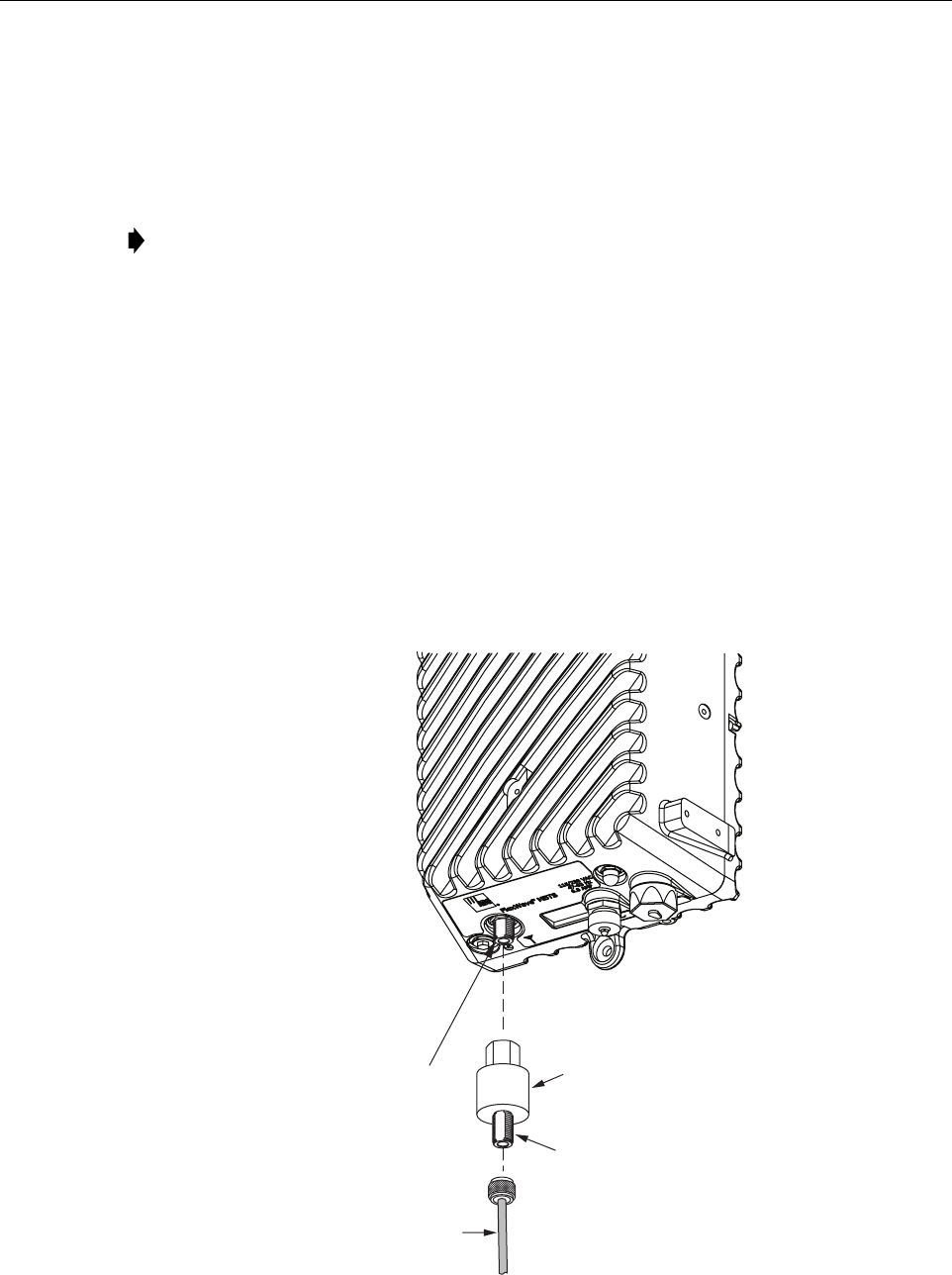
6.2 Ground Wire Installation
A hexagon socket-head capscrew is provided on the underside of the cabinet for attaching a #6
copper grounding wire to the enclosure. A 1.5 meter long #6 AWG copper wire terminated with
a ring terminal is provided for connecting the enclosure to an approved grounding source. Use
the following procedure to install the grounding wire:
1. Locate the 1.5 m #6 AWG (4 mm) copper grounding wire provided with the microBTS
enclosure.
2. Locate the grounding point provided on the underside of the enclosure as shown in
Figure 10.
3. Remove the socket-head capscrew and flat washer from the enclosure using a #6 metric
key or a 7/32-inch hex key wrench.
4. Secure the ring terminal end of the grounding wire to the enclosure using the screw and
washer removed in step 3. Tighten securely.
5. Route the free end of the grounding wire to an approved earth ground source.
6. Cut the ground wire to length and connect it to the earth ground source as specified by
local code or practice.
Caution: For proper and safe equipment operation, an approved earth ground connection must
be provided. The recommended minimum wire size is #6 AWG copper wire.
ADCP-75-246 • Issue 1 • 6/2008
Page 20
© 2008, ADC Telecommunications, Inc.
Figure 10. Connecting Grounding Cable to Enclosure
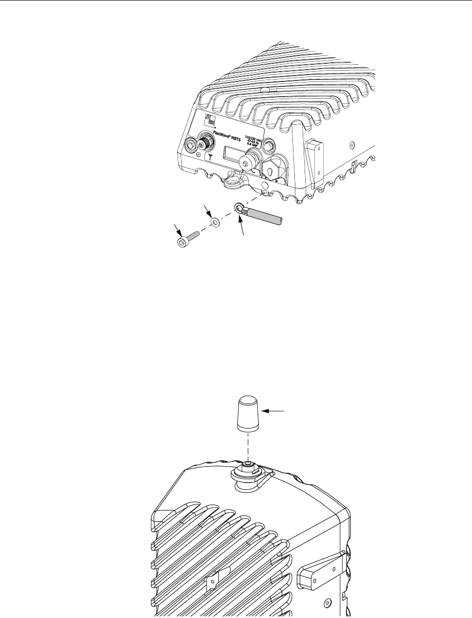
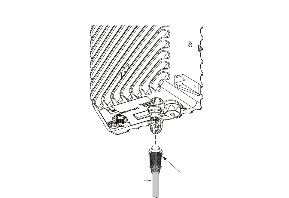
6.3 Network Listen Antenna Installation
The microBTS is shipped with either a Network Listen antenna. Install the antenna by threading
it onto the NMO connector located on the top of the microBTS as shown in Figure 11. Tighten
antenna by hand until secure.
Figure 11. Network Listen Antenna Installation
GROUND
L
UG
FLAT
WASHER
SOCKET
SCREW
22642-A
22650-A
NETWORK LISTEN
ANTENNA
ADCP-75-246 • Issue 1 • 6/2008
Page 21
© 2008, ADC Telecommunications, Inc.
6.4 IP Backhaul Cable Installation
A backhaul cable must be routed from the backhaul device to the microBTS enclosure. The
backhaul cable must be terminated with a hardened RJ-45 male connector for connection to the
microBTS backhaul port. The maximum cable length is 300 feet (91.4 m).
Use the following procedure to install the backhaul cable:
1. Remove the dust cap from the RJ-45 connector located at the bottom of the enclosure as
shown in Figure 12.
2. Route the backhaul cable from the backhaul device to the underside of the enclosure.
3. Align the plug end of the RJ-45 cable connector with the RJ-45 port receptacle and then
insert the cable plug into the port receptacle.
4. Slide the connector nut up to the port until it engages the connector locking mechanism.
5. Tighten the connector nut in a clockwise direction (if necessary, use a wrench or pliers to
grip the connector nut) until it snaps past the detent position and locks into place.
Figure 12. IP Backhaul Cable Installation
Note: It may be necessary to apply 30 to 50 lbs/force-inches (3.4 to 5.6 Nm) of torque to
the connector nut in order to turn it past the detent position.
RJ-45 BACKHAUL
CONNECTOR PORT
BACKHAUL
CABLE
BOTTOM VIEW
22639-A
CONNECTOR
NUT
RJ-45
PLUG
ADCP-75-246 • Issue 1 • 6/2008
Page 22
© 2008, ADC Telecommunications, Inc.
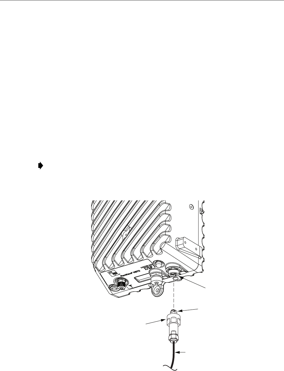
6.5 Base Station Antenna Cable Installation
A coaxial antenna cable must be routed from the base station antenna to the microBTS
enclosure. The cable must be terminated with an N-type male connector for connection to the
microBTS antenna port or the lightning protector (accessory).
Use the following procedure to install the antenna cable(s):
1. Remove the dust cap from the N-type female connector located on the underside of the
enclosure as shown in Figure 13.
2. If specified, connect a lightning protector (accessory) to the antenna port.
3. Route the coaxial antenna cable from the base station antenna to the underside of the
enclosure.
4. Cut the antenna cable to the required length and terminate with an N-type male connector.
5. Connect the antenna cable to the lightning protector or to the antenna port.
Figure 13. Connecting Base Station Antenna Cable to Antenna Port
Note: To comply with Maximum Permissible Exposure (MPE) requirements, the
maximum composite output from the antenna cannot exceed 1640 Watts EIRP and the
antenna must be permanently installed in a fixed location that provides at least 6 meters
(20 feet) of separation from all persons.
BOTTOM VIEW
ANTENNA PORT
(N-TYPE FEMALE)
22640-A
ANTENNA
CABLE
LIGHTNING
PROTECTOR
(ACCESSORY)
SURGE PORT
CONNECTOR
ADCP-75-246 • Issue 1 • 6/2008
Page 23
© 2008, ADC Telecommunications, Inc.
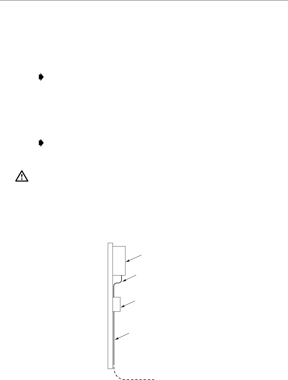
6.6 AC Power Wiring Installation
A 15-foot connectorized 3-wire cable (also available in lengths of 40, 60, or 100 feet) is provided
for the AC power connections. The connectorized end of the cable connects to the AC power port
located on the bottom of the enclosure. The stub end of the cable must be routed to an external
junction box (not provided) for permanent connection to the AC power system wiring.
The AC power source must supply 120 or 240 VAC, 50 or 60 Hz, single-phase power through a
15 Amp circuit breaker. The AC power cable provides three wire leads for line, neutral, and
ground connections. The power cable is rated for indoor or outdoor use and must not be placed
within electrical conduit as this will impede the cooling of the cable during usage. The electrical
junction box and any conduit, wire, and fittings required must be provided by the installer.
Use the following procedure to install the AC power wiring:
1. Locate the AC power cable that is provided separately with the enclosure.
2. Route the power cable between the AC power port, located on the underside of the
enclosure and the nearest AC power junction box as shown in Figure 14. It may be
necessary to install a new junction box if an existing junction box is not available.
Figure 14. Typical AC Power Cable Routing
Note: It is recommended that an AC outlet be installed near the enclosure for powering
tools and test equipment. This outlet must include a GFCI device for protection.
Note: All electrical work must comply with local codes and requirements. A locally
licensed electrical contractor is best qualified to perform this work. For additional
information, consult with the ADC Technical Assistance Center.
Danger: Use extreme caution when working with high voltage AC power. Ensure all power is
disconnected before working on power circuits.
microBTS
ENCLOSURE
22087-A
AC POWER
JUNCTION BOX
AC POWER
CABLE
AC POWER
WIRES ROUTED
TO CIRCUIT
BREAKER PANEL
ADCP-75-246 • Issue 1 • 6/2008
Page 24
© 2008, ADC Telecommunications, Inc.
3. Secure the cable between the AC power port and the AC power junction box per local
practice. Leave sufficient slack in the cable to allow it to be easily connected and
disconnected from the AC power port.
4. Install any AC power supply wires that may be required between the AC junction box and
the AC circuit breaker box.
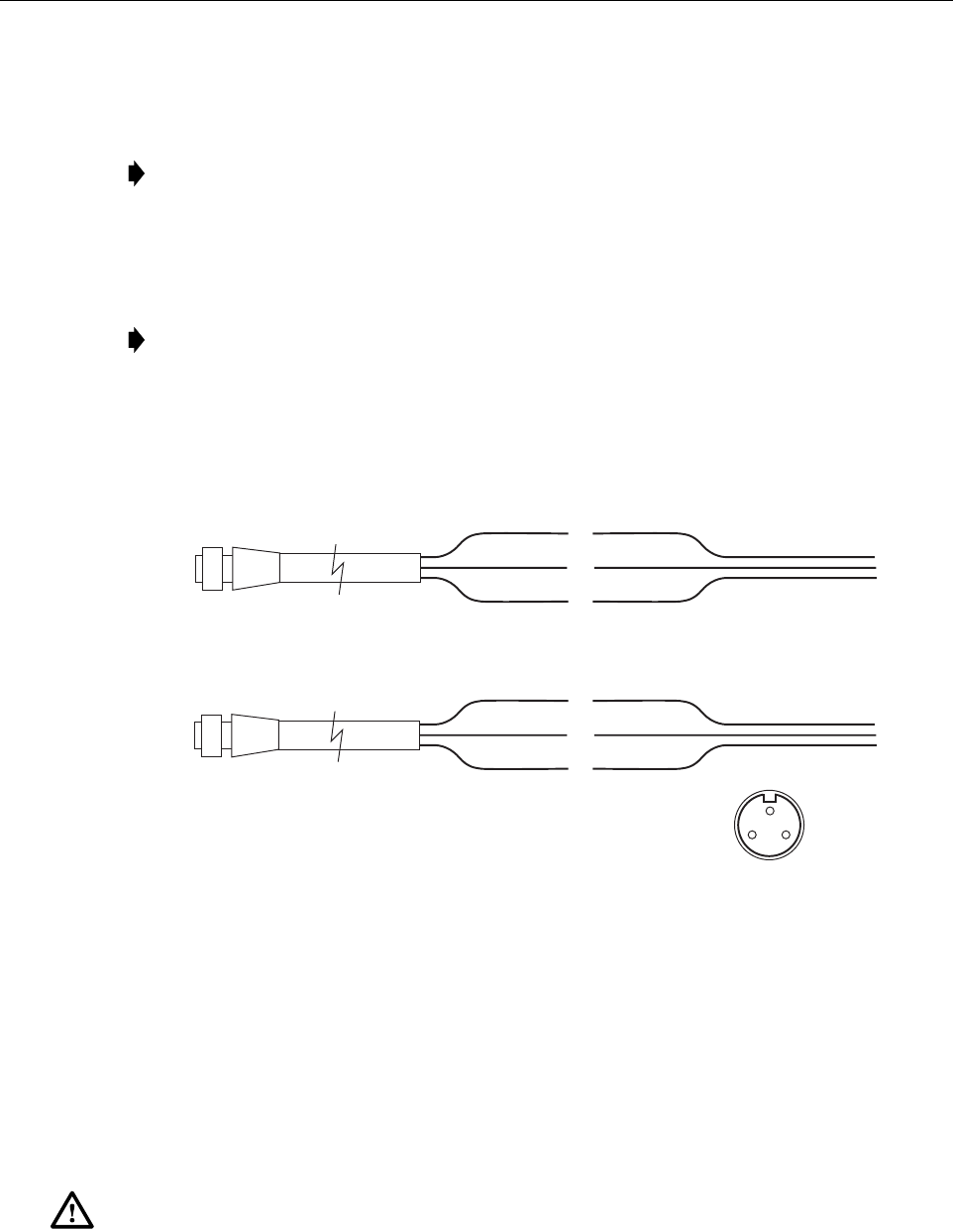
5. Connect the AC power cable wires to the AC power supply wires. Refer to Figure 15 to
identify the color code and wire designations.
Figure 15. AC Power Cable Connections
6. At the AC circuit breaker box, connect the AC power supply load wires to a 15 Amp
circuit breaker.
7. Place the circuit breaker in the ON position and then test the connectorized end of the AC
power cable for proper voltage levels and correct polarity.
8. When testing is complete, place the circuit breaker in the OFF position.
9. Remove the dust cap from the AC power port located on the bottom of the enclosure as
shown in Figure 16.
Note: The power cable is rated for indoor or outdoor use and must not be placed within
electrical conduit as this will impede the cooling of the cable during usage. The cable run
distance to the AC power source must not exceed 100 feet.
Note: It is recommended that an AC outlet be installed near the enclosure for powering
tools and test equipment. This outlet must include a GFCI device for protection.
Danger: While trying to connect the AC power cable to the remote unit AC power port, it is
possible for the line terminal on the cable connector to contact the ground pin on the power
port. If the AC cable is energized, this will result in a direct short to ground for the AC power. To
avoid possible personal injury and equipment damage, always turn the AC power off before
connecting the AC power cable to the AC power port.
AC POWER CORD
PROVIDED WITH ENCLOSURE BLACK
GREEN/YELLOW
WHITE
LINE
GROUND
NEUTRAL
120 VAC POWER
WIRING
AC POWER CORD
PROVIDED WITH ENCLOSURE BLACK
GREEN/YELLOW
WHITE
LINE 1
GROUND
LINE 2
240 VAC POWER
WIRING
120 VAC CONNECTIONS
240 VAC CONNECTIONS
20778-A
CONNECTOR PIN DESIGNATIONS
PIN 1 - GREEN/YELLOW
PIN 2 - WHITE
PIN 3 - BLACK
END VIEW OF
CONNECTOR
12
3
ADCP-75-246 • Issue 1 • 6/2008
Page 25
© 2008, ADC Telecommunications, Inc.
Figure 16. Connecting AC Power Cable to Enclosure
10. Connect the power cable connector to the AC power port.
11. Tighten coupling nut until the green band at the top of the connector body is visible.
6.7 Touch-Up Painting
A brush-in-cap type bottle of paint (ACE-ACC-PTLAMD) is available for touching-up nicks
and scratches in the factory coat of paint. Lightly sand the area to be painted and then clean it
thoroughly to remove and dirt, dust, or foreign matter. Shake the paint bottle until thoroughly
mixed and then apply a light coat of paint to the damaged area using the small brush attached to
the cap. Wait until the paint is dry and apply a second coat if necessary. When finished painting,
replace the paint bottle cap and tighten securely.
6.8 Power-Up and Testing
When the installation is complete, refer to the applicable publications for the system turn-up and
test procedures. To verify that the microBTS is ready to be placed into service, place the AC
breaker in the closed (on) position and observe the LED indicator light on the bottom of the
enclosure. The LED indicator should turn red immediately following power-up. The LED will
continue to stay red for up to 30 minutes following the initial power-up during which time the
microBTS will synchronize with an external clock source. When the microBTS timing has been
synchronized, the LED will turn off.
BOTTOM VIEW
22641-A
POWER
CABLE
GREEN BAND WILL BE
VISIBLE WHEN COUPLING
NUT IS TIGHTENED

ADCP-75-246 • Issue 1 • 6/2008
Page 26
© 2008, ADC Telecommunications, Inc.
6.9 microBTS Replacement
The microBTS enclosure contains no user-replaceable or field-serviceable components. Failure
of any internal component will require replacement of the entire unit. The enclosure mounting
hardware, the various cables, and any attached antenna systems may be reused with the
replacement unit. Opening the microBTS enclosure for any reason may cause the product
warranty to be null and void.
ADCP-75-246 • Issue 1 • 6/2008
Page 27
© 2008, ADC Telecommunications, Inc.
7 CUSTOMER INFORMATION AND ASSISTANCE
13944-Q
Contents herein are current as of the date of publication. ADC reserves the right to change the contents
without prior notice. In no event shall ADC be liable for any damages resulting from loss of data,
loss of use, or loss of profits and ADC further disclaims any and all liability for indirect, incidental,
special, consequential or other similar damages. This disclaimer of liability applies to all products,
publications and services during and after the warranty period.
REPRINTS:
www.adc.com/manuals
PDF copies of manuals are available
for downloading at the following link:
PRODUCT INFORMATION AND TECHNICAL ASSISTANCE:
connectivity.tac@adc.com
wireless.tac@adc.com
euro.tac@adc.com
asiapacific.tac@adc.com
ADCP Number:
WRITE:
ADC Telecommunications (S’PORE) PTE, LTD;
100 Beach Road, #18-01, Shaw Towers.
Singapore 189702.
ADC Telecommunications, INC
PO Box 1101,
Minneapolis, MN 55440-1101, USA
ADC European Customer Service, INC
Belgicastraat 2,
1930 Zaventem, Belguim
PHONE:
U.S.A. or CANADA
Sales: 1-800-366-3891
Extension 73000
Technical Assistance: 1-800-366-3891
Connectivity Extension: 73475
Wireless Extension: 73476
EUROPE
Sales Administration: +32-2-712-65 00
Technical Assistance: +32-2-712-65 42
EUROPEAN TOLL FREE NUMBERS
Germany: 0180 2232923
UK: 0800 960236
Spain: 900 983291
France: 0800 914032
Italy: 0800 782374
ASIA/PACIFIC
Sales Administration: +65-6294-9948
Technical Assistance: +65-6393-0739
ELSEWHERE
Sales Administration: +1-952-917-3000
Technical Assistance: +1-952-917-3475
ADCP-75-246

Website: www.adc.com