ADC Telecommunications PSM230WM FWP-W4MT000MOD User Manual
ADC Telecommunications Inc FWP-W4MT000MOD
user manual
Dual-Band Dual-Slot RF Module
Single-Slot RF Module
Legacy Dual-Slot 40W RF Module
HDM RF Module
FlexWave
Prism Remote Unit RF Module
Installation Guide
TECP-77-141 · Issue 8 · August 2015
TE Connectivity, TE and TE connectivity (logo) FlexWave, InterReach, InterReach Fusion and InterReach Unison are trademarks.
All other logos, products and/or company names referred to herein might be trademarks of their respective owners.
The information given herein, including drawings, illustrations and schematics which are intended for illustration purposes only, is believed to be reliable. However, TE
Connectivity makes no warranties as to its accuracy or completeness and disclaims any liability in connection with its use. TE Connectivity's obligations shall only be as
set forth in TE Connectivity's Standard Terms and Conditions of Sale for this product and in no case will TE Connectivity be liable for any incidental, indirect or
consequential damages arising out of the sale, resale, use or misuse of the product. Users of TE Connectivity products should make their own evaluation to determine
the suitability of each such product for the specific application.
This installation guide provides the information you need to install TE Connectivity FlexWave Prism RF Modules
into a Prism Remote Unit (PRU).
Installation instructions are provided for the following Prism Remote Unit RF Modules:
•Single-Bay RF Modules, which includes the HDM RF Modules
•Dual-Bay RF Modules
–Dual-Band RF Modules
–Legacy 40W RF Modules.

Page 2 FlexWave Prism Remote Unit RF Module Installation Guide
©2015 TE Connectivity TECP-77-141 Issue 8 • 300001744178 Rev H • August 2015
TABLE OF CONTENTS
Document Overview ...........................................................................................................................................................................................3
Revision History.......................................................................................................................................................................................................5
Document Cautions and Notes ...............................................................................................................................................................................5
Abbreviations Used in this Guide............................................................................................................................................................................5
Overview of RF Modules for Prism Remote Units ................................................................................................................................................6
RF Module Digital/Analog Radio Transceivers ........................................................................................................................................................7
RF Module Types.....................................................................................................................................................................................................9
Single- and Dual-Bay RF Modules with Classic or SuperDARTs .......................................................................................................................9
HDM RF Modules ..........................................................................................................................................................................................10
Legacy Dual-Bay 40W RF Modules ................................................................................................................................................................11
RF Module Components ....................................................................................................................................................................................12
Linear Power Amplifiers ........................................................................................................................................................................................13
Duplexer and Low Noise Amplifier........................................................................................................................................................................14
Digital Processing Module.....................................................................................................................................................................................14
Cables ....................................................................................................................................................................................................................14
RF Group Assignments for PRU RF Module Bays ................................................................................................................................................15
Understanding RF Cable Rules...........................................................................................................................................................................18
RF Module Cables and Supported Bay Use for Single-Card, Dual-Card, and HDM RF Modules ...........................................................................18
RF Module Cables and Supported Bay Installations for Legacy Dual-Bay 40W RF Modules.................................................................................20
Install the RF Module(s) ....................................................................................................................................................................................21
Safety Precautions.................................................................................................................................................................................................21
Guard against Damage from Electro-Static Discharge ..........................................................................................................................................22
Unpack and Inspect the RF Module ......................................................................................................................................................................22
Remove Release Liners from the RF Module ........................................................................................................................................................23
Check the DC Power Switch for the Module Bay ..................................................................................................................................................24
Dual-Bay Modules Only—Remove the Module Bay Shelf.....................................................................................................................................25
Install the RF Module into the Prism Remote Chassis...........................................................................................................................................26
Secure RF Module Latches ....................................................................................................................................................................................34
Connect Latches on Single-Bay and HDM RF Modules .................................................................................................................................34
Connect Latches on Dual-Bay RF Modules....................................................................................................................................................35
Latches on Legacy Dual-Bay 40W RF Modules..............................................................................................................................................36
Verify that the RF Module Mounting Hook is Engaged.................................................................................................................................36
Connect the RF Module Cables to the PRU Chassis ..............................................................................................................................................36
Connecting Cables in a Single-Bay RF Module Installation ...........................................................................................................................37
Connecting Cables in a Dual-Bay RF Module Installation..............................................................................................................................40
Power on the RF Module(s) and the Prism Remote Unit......................................................................................................................................44
Close the Remote Unit Door and Solar Shield.......................................................................................................................................................46
Provision the Prism Remote Unit..........................................................................................................................................................................46
FlexWave Notch Filter (FWP-SPRINTFILTER) ......................................................................................................................................................47
Standards Certification......................................................................................................................................................................................49
Accessing User Documentation on the TE Customer Portal................................................................................................................................50
Contacting TE Connectivity................................................................................................................................................................................51

FlexWave Prism Remote Unit RF Module Installation Guide Page 3
TECP-77-141 Issue 8 • 300001744178 Rev H • August 2015 ©2015 TE Connectivity
DOCUMENT OVERVIEW
Table 1 lists the RF Modules that this installation guide supports.
Table 1. FlexWave Prism RF Modules Supported in this Installation Guide
Catalog Number Description
High-Density Module (HDM); Single Bay
FWP-L4MT000MOD 20W 700 lABC Module, MIMO HDM, Single-Bay
FWP-L4MTU4MMOD 20W 700 lABC/700uC, Dual, Single-Bay
FWP-U4MT000MOD 20W 700 uC Module, MIMO HDM, Single-Bay
FWP-44MT000MOD 20W 800 MIMO, Single Bay, with two External Filters
FWP-441T841MOD 20W 800 SMR/ 1900 PCS, Dual RF Module
FWP-C4MT000MOD 20W 850 Cell/1900 PCS, Dual, Single-Bay
FWP-B4MT000MOD 20W 850 DUAL, MIMO, Single Bay
FWP-84MT000MOD 20W 1900 PCS Dual MIMO, Single-Bay
FWP-84MTA4MMOD 20W 1900/2100 Dual, Single Bay
FWP-W4MT000MOD 20W 2300 WCS FDD, MIMO HDM, Single-Bay
FWP-A416000MOD 20W AWS Module, Non-Diversity, HDM, Single Bay
FWP-A4MT000MOD 20W AWS Band 4 MIMO HDM, Single-Bay
FWP-8416000MOD 20W PCS Module, Non-Diversity, HDM, Single Bay
FWP-B410000MOD 20W Wideband Cell Module, Non-Diversity
FWP-A81T000MOD 40W AWS Band 4 SISO HDM, Single-Bay
FWP-881T000MOD 40W PCS Band 2 & 25 SISO HDM, Single-Bay
FWP-B810100MOD 40W Wideband Cell Module, Non-Diversity, Single-Bay
Single SuperDART; Single Bay
FWP-I210000MOD 6.5W 800 APAC Module, Non-Diversity, Classic (Extended 1 MHz)
FWP-6216000MOD 10W 900 EGSM, Non-Diversity, Single SuperDART
FWP-K216000MOD 10W 900 P-GSM Module, Non-Diversity, Single SuperDART
FWP-F216000MOD 10W APAC EGSM Module, Single SuperDART
FWP-7416000MOD 20W 1800 GSM, Non-Diversity, Single SuperDART
FWP-9416D00MOD 20W 2100 UMTS Module, DIV Ready, Single SuperDART
FWP-9416000MOD 20W 2100 UMTS, Non-Diversity, Single SuperDART
FWP-L416000MOD 20W 700 Lower ABC Module, Non-Diversity, Single SuperDART
FWP-U416000MOD 20W 700 LTE, UPPER C, SISO, Single SuperDART
FWP-U816100MOD 40W 700 Upper C Module, Non-Diversity, Single SuperDART, Single-Bay
Dual SuperDART; Single Bay
FWP-741S000MOD 20W 1800 GSM, Non-Diversity, DL SuperDART
FWP-A41S000MOD 20W AWS 2100 12S
FWP-841S000MOD 20W PCS 1900 12S
FWP-941S000MOD 20W, UMTS 2100, Non-Diversity, DL SuperDART
Page 4 FlexWave Prism Remote Unit RF Module Installation Guide
©2015 TE Connectivity TECP-77-141 Issue 8 • 300001744178 Rev H • August 2015
The RF Modules listed in Table 1 are compatible only with the Remote Units listed in Table 2.
Table 2. Supported FlexWave Prism Remote Unit Chassis
Catalog Number Description
Single-Bay Prism Remote
Dual-Bay Prism Remote
Tri-Bay Prism Remote
Quad-Bay Prism Remote
Two Single SuperDARTs; Diversity; Single Bay
FWP-6226000MOD 10W 900 EGSM, Diversity, Single SuperDART
FWP-K226000MOD 10W 900 P-GSM Module, Diversity, Single SuperDART
FWP-7426000MOD 20W 1800 GSM, Diversity, Single SuperDART
FWP-9426000MOD 20W, 2100 UMTS, Diversity, Single SuperDART
FWP-A426000MOD 20W AWS Module, Diversity, Single SuperDART
FWP-8426000MOD 20W PCS Module, Diversity, Single SuperDART
Classic DART; Single Bay
FWP-4210000MOD 6.5W 800 SMR Module, Non-Diversity, Classic
FWP-8420000MOD 20W 1900 PCS Diversity
FWP-8410000MOD 20W 1900 PCS Non-Diversity
FWP-A420000MOD 20W 2100 AWS Diversity
FWP-A410000MOD 20W 2100 AWS Non-Diversity
FWP-B420000MOD 20W Wideband Cell Module, Diversity, Classic
FWP-J410D00MOD 20W 850 Cell (870-890) Module, Diversity Ready, Classic
Classic DART; Two-Bay
FWP-8810000MOD 40W PCS Module, Non-Diversity, Classic (Dual-Bay)
FWP-A810000MOD 40W AWS Module, Non-Diversity, Classic, Dual-Bay
Dual Classic DART; Two-Bay
FWP-D210000MOD 6.5W 800/900 ESMR Module, Non-Diversity, Classic
FP1-XXXXXXXXXXXRU
FP2-XXXXXXXXXXXRU
FP3-XXXXXXXXXXXRU
FP4-XXXXXXXXXXXRU
Table 1. FlexWave Prism RF Modules Supported in this Installation Guide (Cont.)
Catalog Number Description

FlexWave Prism Remote Unit RF Module Installation Guide Page 5
TECP-77-141 Issue 8 • 300001744178 Rev H • August 2015 ©2015 TE Connectivity
Revision History
Table 3. Revision History
Issue Document Date Technical Updates
1April 2012 Original
2February 2013 Changed Prism Remote Unit model names from Single-/Dual-/Tri-/Quad-Band to Single-/Dual-/Tri-/Quad-Bay.
(TECP-77-201).
3May 2013 Added “Understanding RF Cable Rules” on page 18..
4October 2013 Added the 20W AWS Band 4 MIMO HDM, 40W AWS Band 4 SISO HDM and 40W PCS Band 25 SISO HDM RF Modules.
5January 2014 Added FWP-84MT000MOD and FWP-L4MTU4MMOD RF Modules, and added Table 13 on page 39.
6August 2014 Added support for FWP-B4MT000MOD, FWP-44MT000MOD, and FWP-84MTA4MMOD RF Modules; added the external
FlexWave Notch Filter (FWP-SPRINTFILTER), see “FlexWave Notch Filter (FWP-SPRINTFILTER)” on page 47.
7December 2014 Added caution about potential temporary loss of RF for HDM RF Modules after closing the chassis door.
8March 2015 Adds support for the Dual 20W 2300 WCS FDD, MIMO, Single-Bay RF Module (FWP- W4M T000MOD); adds “Close
the Remote Unit Door and Solar Shield” on page 46.
Document Cautions and Notes
Two types of messages, identified below, appear in the text:
CAUTION! Cautions indicate operations or steps that could cause personal injury, induce a safety problem in a
managed device, destroy or corrupt information, or interrupt or stop services.
NOTE: Notes contain information about special circumstances.
Abbreviations Used in this Guide
CDRH Center for Diseases and Radiological Health LVDS Low-Voltage Differential Signaling
cm Centimeter MHz Megahertz
DART Digital/Analog Radio Transceiver MIMO Multiple-Input Multiple-Output
dB Decibel MOD Module
dBm Decibel-milliwatts PA Power Amplifier
DCS Distributed Call Signaling PRIM Primary
DD Digital Dividend PRU Prism Remote Unit
DIV Diversity PWR Power
DPM Digital Processing Module REV Reverse
EMC Electromagnetic Compatibility RF Radio Frequency
ESD Electro-Static Discharge Rx Receive
EU European Union SDART Super Digital/Analog Radio Transceiver
FCC Federal Communications Commission SeRF Serialized RF
FDA Food and Drug Administration SFP Small Form-Factor Pluggable
FRU Fullband Remote Unit TIM Thermal-Interface Material
FWD Forward Tx Transmit
HDM High Density Module UL Underwriters' Laboratories, Inc.
HMFOC Hardened Multi-Fiber Optic Connector UMTS Universal Mobile Telecommunications System
IC Industry Canada WWatt
LED Light-Emitting Diode WCS Wireless Communications Services
Page 6 FlexWave Prism Remote Unit RF Module Installation Guide
©2015 TE Connectivity TECP-77-141 Issue 8 • 300001744178 Rev H • August 2015
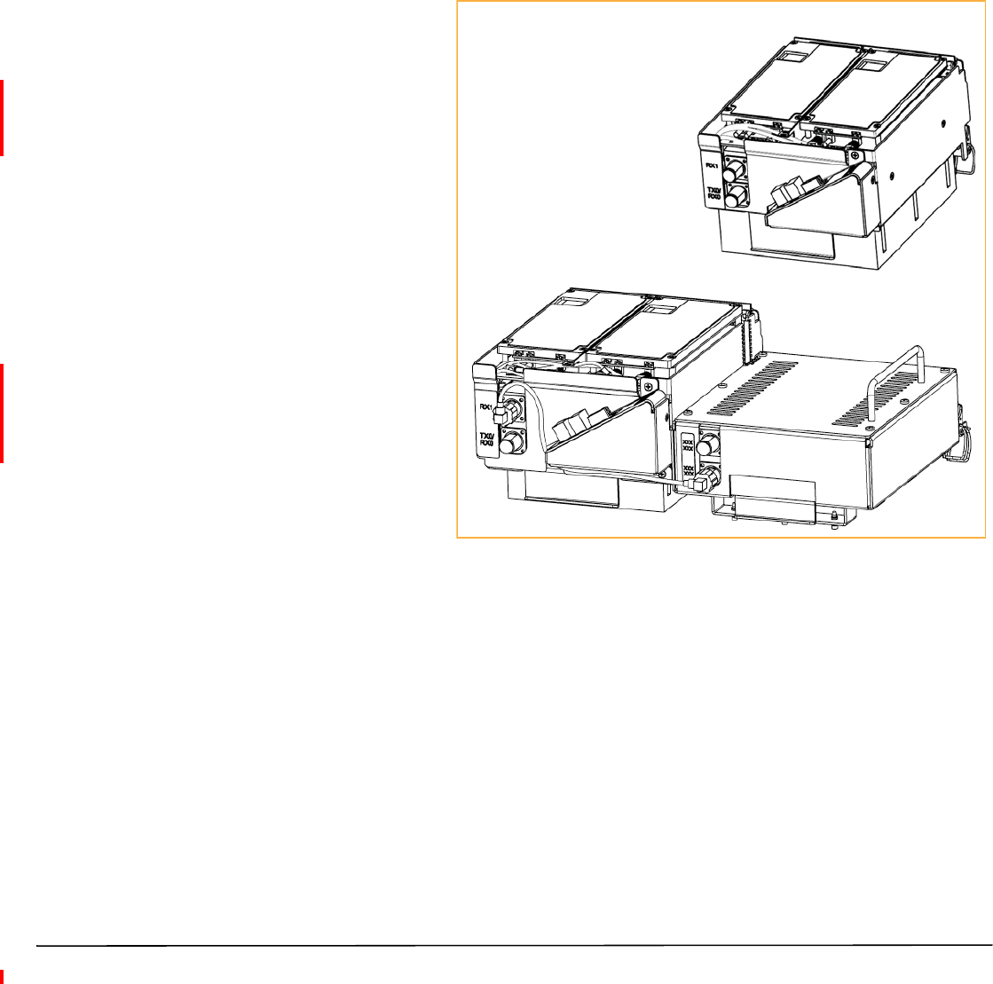
OVERVIEW OF RF MODULES FOR PRISM REMOTE UNITS
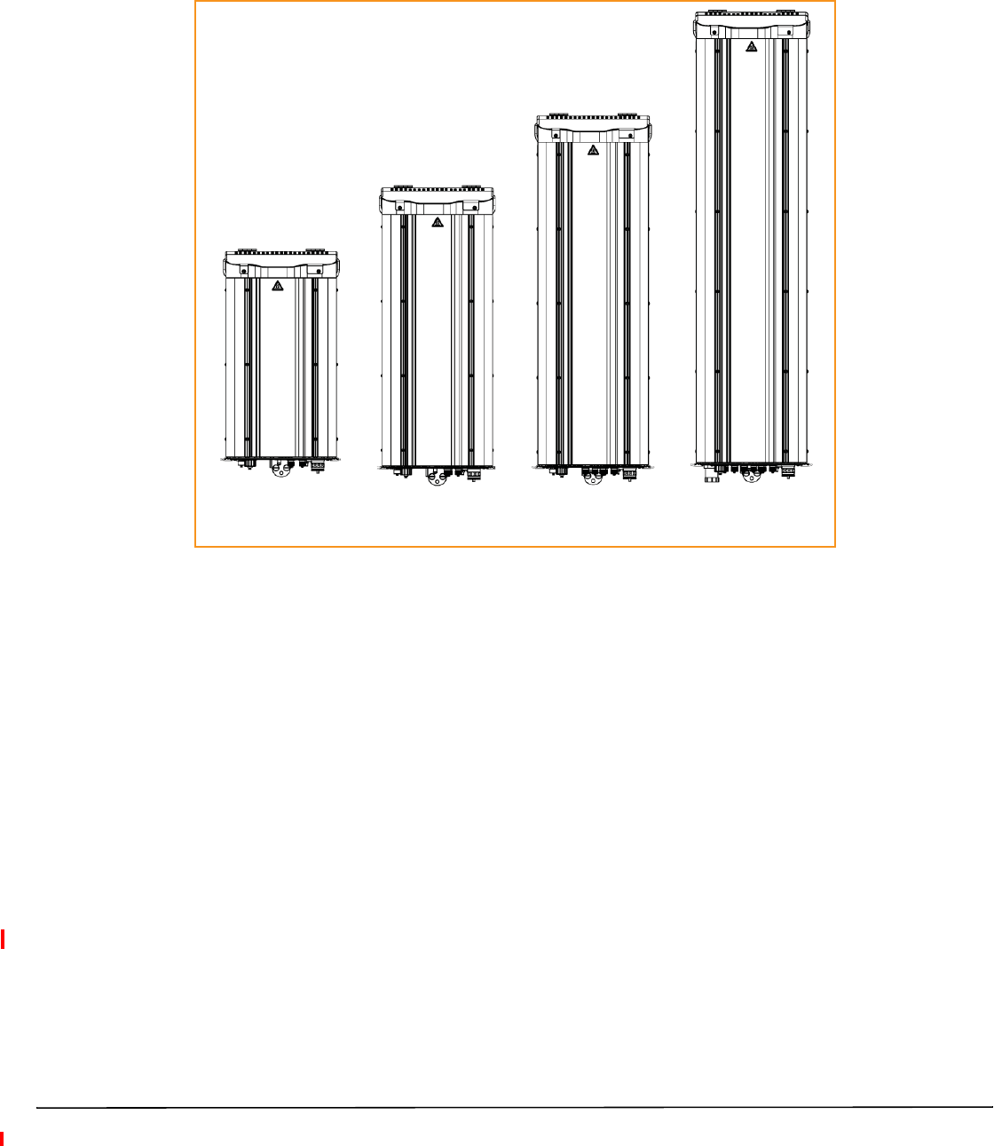
Figure 1 illustrates the Prism Remote Unit (PRU), which controls RF emissions, interfaces with the FlexWave
Prism Host Unit.
Single-Bay
Prism Remote Unit
Dual-Bay
Prism Remote Unit
Tri-Bay
Prism Remote Unit
Quad-Bay
Prism Remote Unit
Figure 1. Prism Remote Units (PRUs)
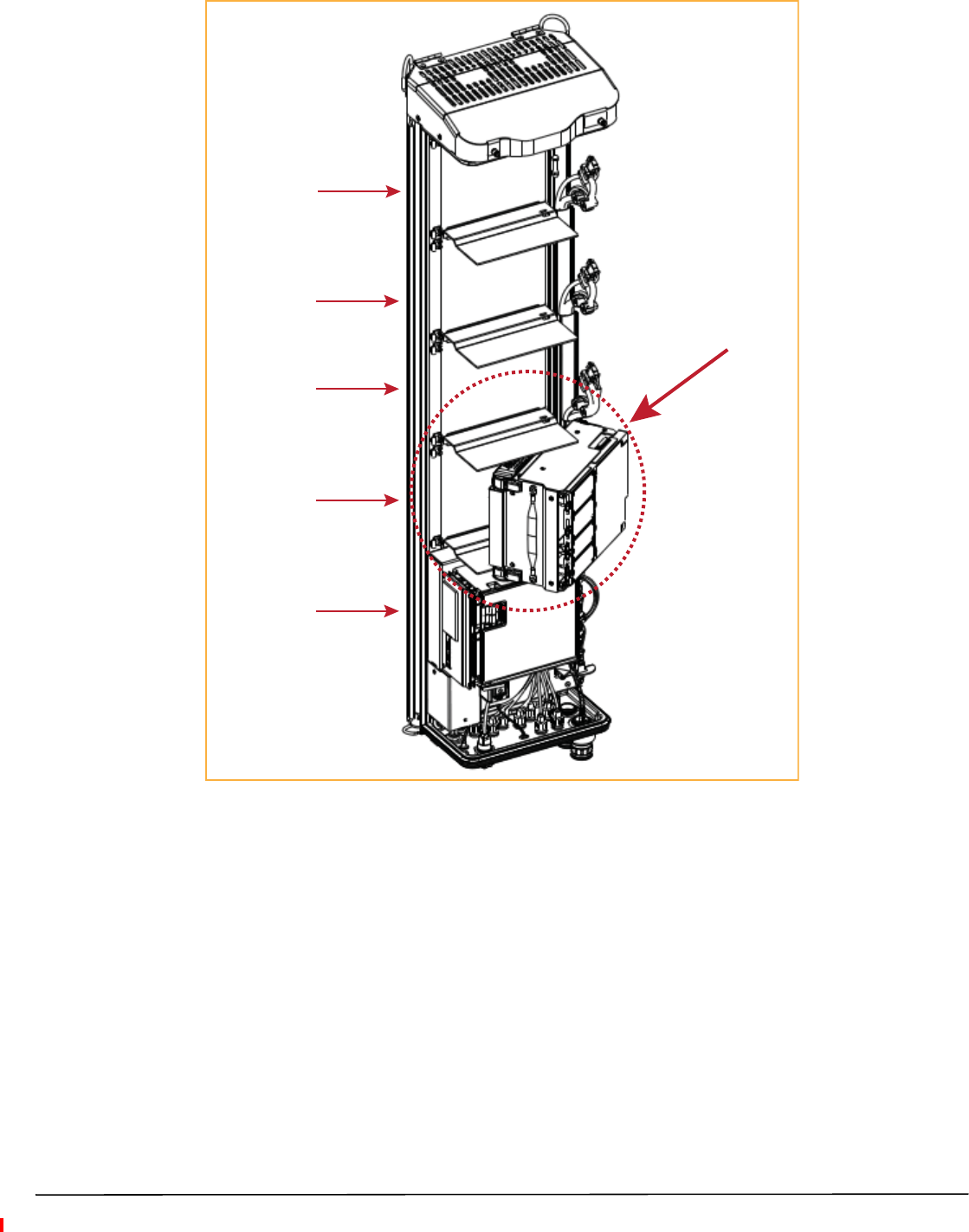
Depending on the Prism Remote Unit model, a PRU enclosure can have from one to four RF Module bays and can
support up to four RF Modules, as indicated by the model name. That is, the Single-Bay PRU has one RF Module
bay and can only support one RF Module, and the Quad-Bay PRU has four RF Module bays and can support up to
four RF Modules.
The function of the Remote Unit RF Modules on the Forward Path is to:
•convert the digitized RF transported from the Host to Analog RF
•amplify the Analog RF signal
•provide signal filtering.
The function of the Remote Unit RF Modules on the Reverse Path is to:
•convert the Analog RF from the handset to Digital RF for transport to the Host
•amplify the Digital RF signal
•provide signal filtering.
NOTE: The RF Modules are field replaceable, but cannot be serviced in the field.
FlexWave Prism Remote Unit RF Module Installation Guide Page 7
TECP-77-141 Issue 8 • 300001744178 Rev H • August 2015 ©2015 TE Connectivity
RF Module Digital/Analog Radio Transceivers
Each RF Module can support any of the following Digital/Analog Radio Transceiver (DART) combinations:
•one Classic DART or one Single SuperDART
•two Classic DARTs (i.e., the 6.5W 800/900 ESMR Module, Non-Diversity, Classic)
•two Classic DARTs—Diversity
•two Single SuperDARTs—Diversity
•one Dual SuperDART
•one or two sets of Tx and Rx Boards (HDM).
Each RF Module will have up to two 6-timeslot DARTs or one 12-timeslot DART per RF Module.
The DART type determines the maximum number of links, where there can be up to eight Classic DARTs or Single
SuperDARTs that support 39 MHz each, or up to 4 Dual SuperDARTs that support up to 75MHz each.
Prism supports the DART Module types listed below.
•Classic DARTs are 6-timeslot DARTs that support up to 35 MHz contiguous bandwidth (see Table 4 on
page 7).
•Single SuperDARTs are 6-timeslot DARTs that support two non-contiguous bands in the entire frequency
range of the DART, but cannot exceed 39 MHz total RF bandwidth (see Table 5 on page 8).
•Dual SuperDARTs are 12-timeslot DARTs that support up to 60-75 MHz (see Table 6 on page 8)
Table 4. Single-Position Classic DARTs
DART Module Type Maximum Bandwidth (MHz) Maximum Fiber Slots
800 APAC iDEN Classic 19 3
800 SMR Classic 7* 3
850 Cell Classic 25 4
900 SMR Classic 5 1
* Classic Prism RF Modules and Spectrum RAU support 18 MHz; Prism HDM 800
only supports 7 MHz, per Sprint direction.
NOTE: Industry Canada PCS 20 dB nominal bandwidth is less than 61.5 MHz.
NOTE: Industry Canada AWS 20 dB nominal bandwidth is less than 47.2 MHz
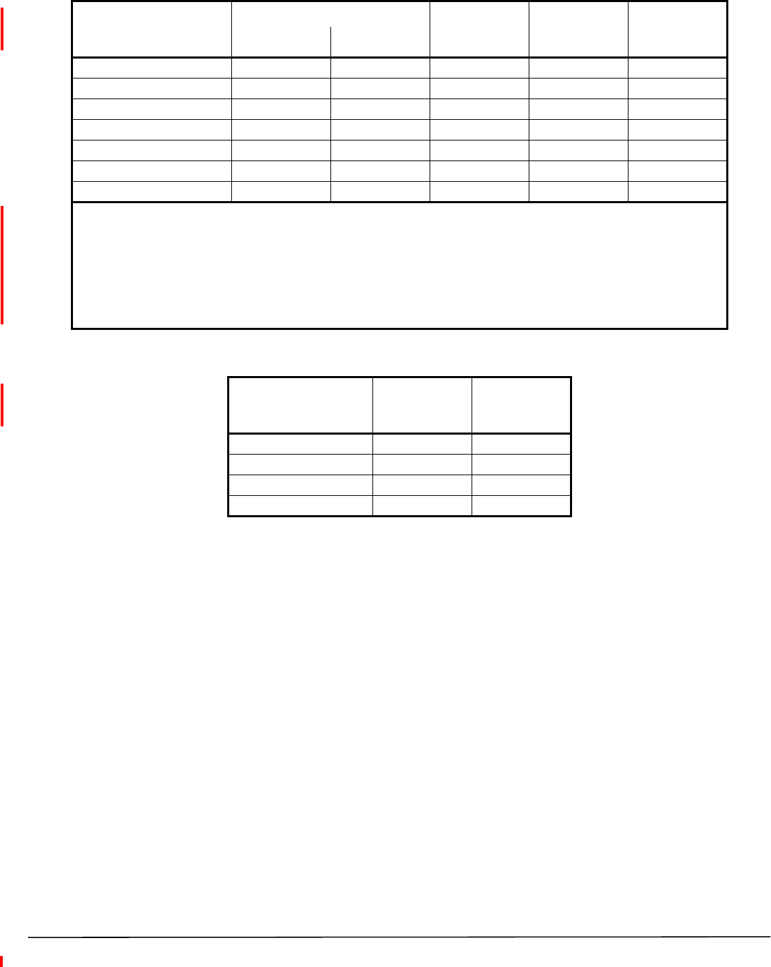
Table 5. Single-Position SuperDARTs(1)
DART Name Used in… Maximum
Frequency
Span (MHz)
Maximum
Bandwidth
(MHz)
Maximum
Fiber
Slots
Host Units HEUs
1800 GSM SGL SuperDART Yes No 75 39 6
1900 PCS SGL SuperDART Yes Yes 70 39 6
2100 AWS SGL SuperDART Yes Yes 45 39 6
2100 UMTS SGL SuperDART Yes No 60 39 6
700 IABC SGL SuperDART Yes Yes 18 18 3
700 uC SGL SuperDART Yes Yes 10 10 2
900 EGSM SGL SuperDART Yes No 35 35 6
(1) When using a Host Unit with both a SeRF II and System Board II or III, the bandwidths and fiber for the following Single
SuperDARTs can be greater than 6 fiber slots, for full-band capability, when used in Host Unit Slots 1 and 3:
•1800 GSM SGL SuperDART
•1900 PCS SGL SuperDART
•2100 AWS SGL SuperDART
•2100 UMTS SGL SuperDART
This requires 12 fiber slots when full-band passband is selected for these Single SuperDARTs in Host Unit DART positions 1
and 3.
Table 6. Dual-Position SuperDARTs
DART Module Type Maximum
Bandwidth
(MHz)
Maximum
Fiber
Slots
1800 GSM DL SuperDART 75 12
1900 PCS DL SuperDART 70 12
2100 AWS DL SuperDART 45 8
2100 UMTS DL SuperDART 60 12
Page 8 FlexWave Prism Remote Unit RF Module Installation Guide
©2015 TE Connectivity TECP-77-141 Issue 8 • 300001744178 Rev H • August 2015
FlexWave Prism Remote Unit RF Module Installation Guide Page 9
TECP-77-141 Issue 8 • 300001744178 Rev H • August 2015 ©2015 TE Connectivity
RF Module Types
The Remote Unit RF Modules are available in the following formats, and as described in the following sections:
•“Single- and Dual-Bay RF Modules with Classic or SuperDARTs” on page 9
•“HDM RF Modules” on page 10
•“Legacy Dual-Bay 40W RF Modules” on page 11.
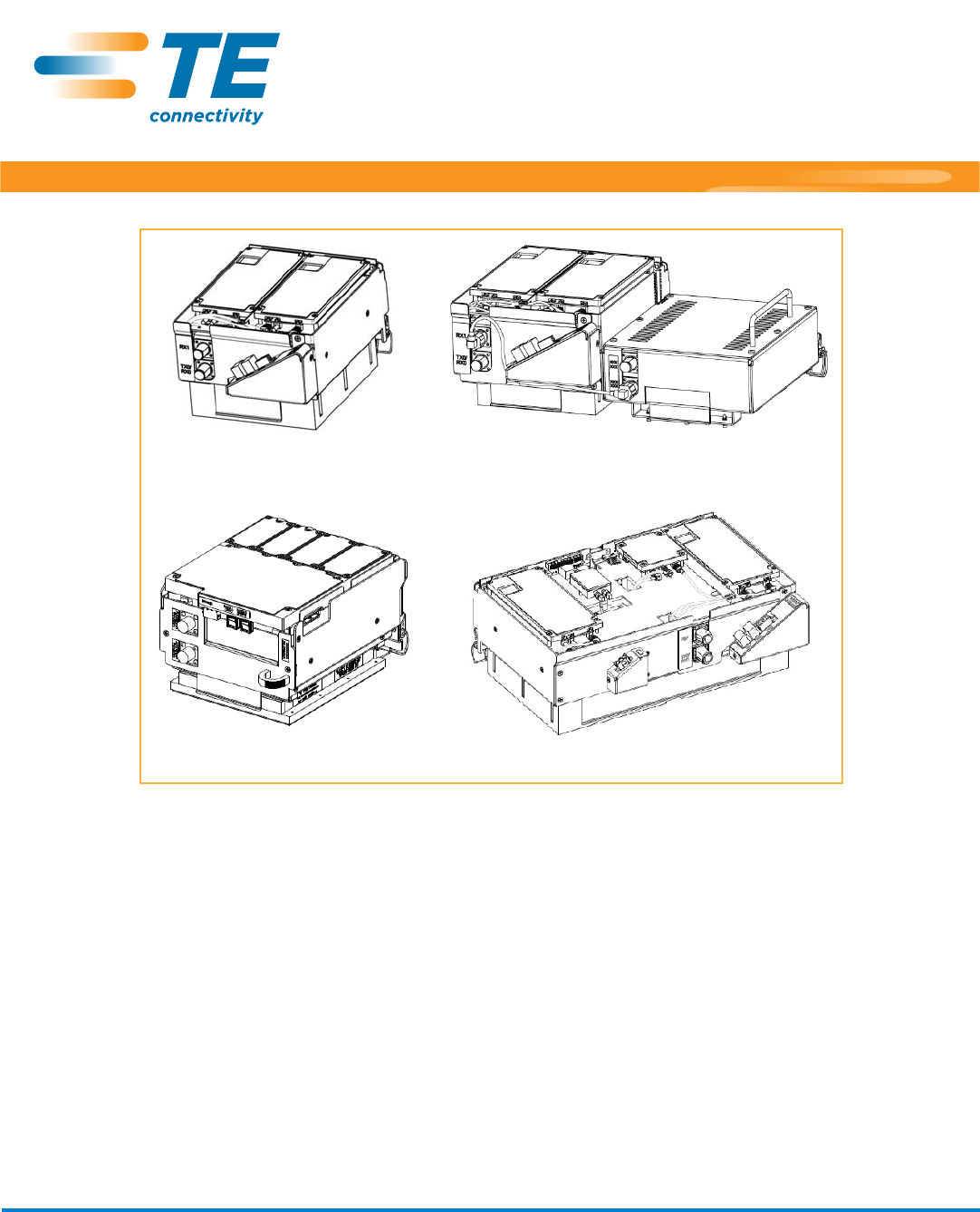
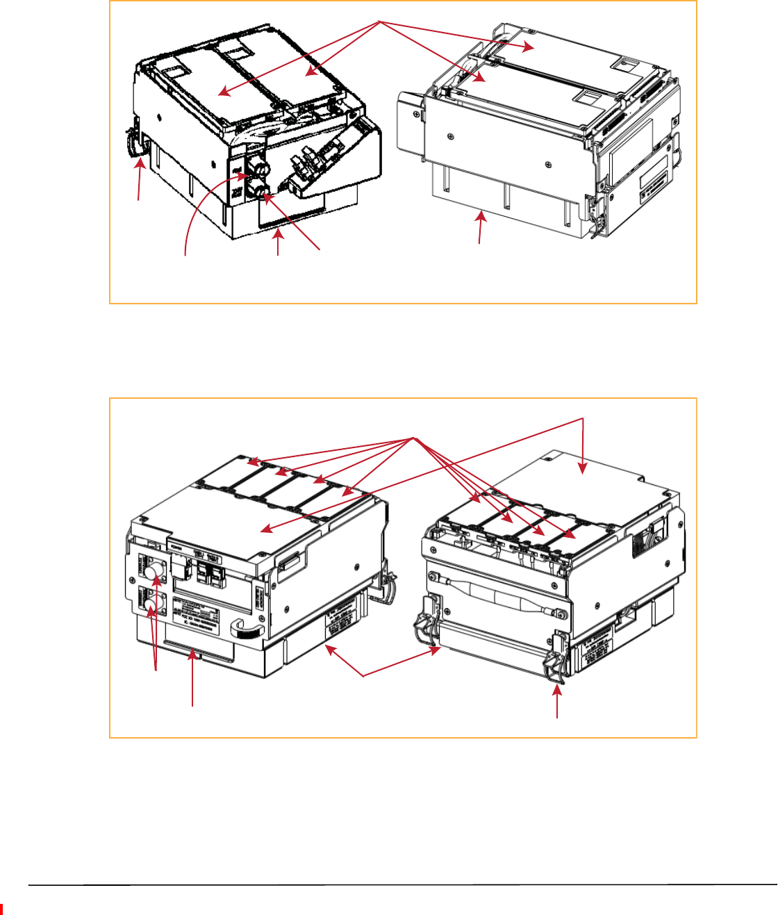
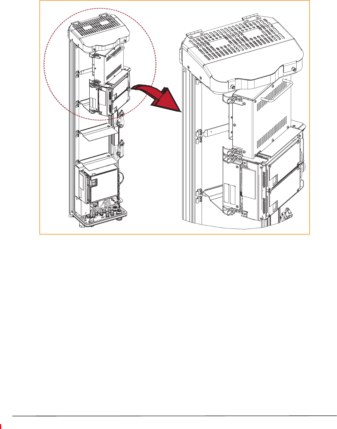
Single- and Dual-Bay RF Modules with Classic or SuperDARTs
Figure 2 shows examples of Single- and Dual-Bay RF Modules, both of which have two DARTs.
Single-Bay RF Modules have the
following elements:
•one or two DARTs
•one Duplexer that comprises
–one Low Noise Amplifier (LNA)
–one Power Detector (PD)
•one Linear Power Amplifier (LPA)
Dual-Band Dual-Bay RF Modules have the
following elements:
•two DARTs
•two Duplexers, each of which
comprises
–one Low Noise Amplifier (LNA)
–one Power Detector (PD)
•one Linear Power Amplifier (LPA)
•one Remote DART Interface (RDI)
board.
Dual-Band Dual-Bay RF Module
Single-Bay Dual-Card RF Module
Figure 2. Single- and Dual-Bay RF Modules
•one Remote DART Interface (RDI)
board.
Page 10 FlexWave Prism Remote Unit RF Module Installation Guide
©2015 TE Connectivity TECP-77-141 Issue 8 • 300001744178 Rev H • August 2015
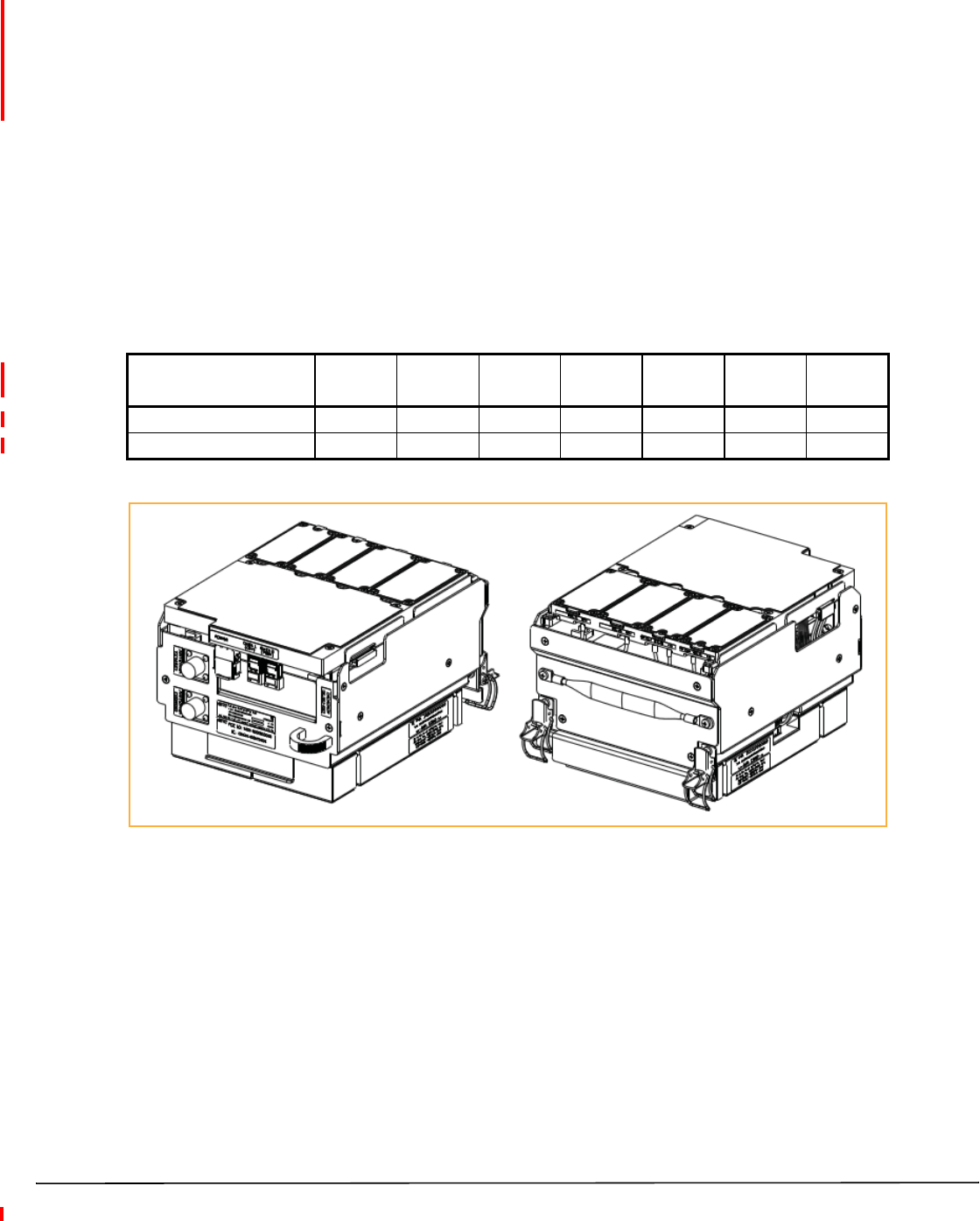
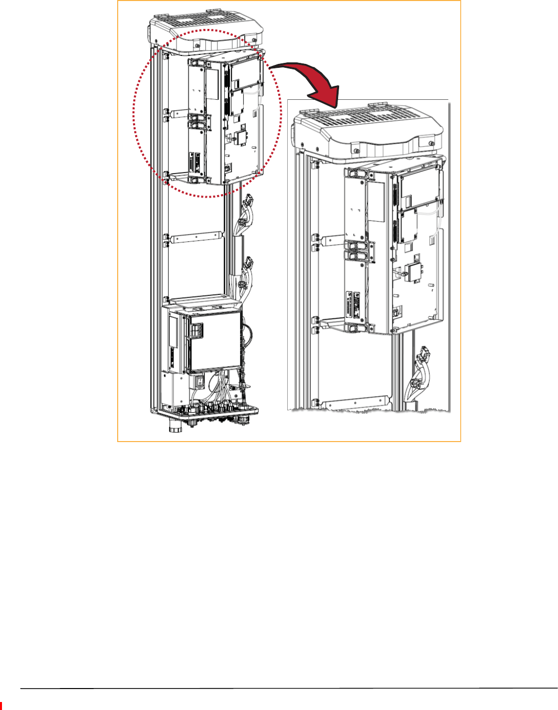
HDM RF Modules
High-Density Module (HDM) RF Modules (Figure 3) are designed to provide the ability to deploy either a two
20W Multiple Input Multiple Output (MIMO) paths of the same band, known as a MIMO RF Module; two 20W
Single Input Single Output (SISO) with two different bands, known as dual RF Module; or a single 40W Single
Input Single Output (SISO) RF Module within a single-bay of a PRU. An HDM RF Module does the following:
•interfaces with one Host DART-either Classic or SuperDART, or one CDIU
•supports two non-contiguous RF slices up to 39 MHz total bandwidth in a Dual or MIMO configuration
•supports full bandwidth in a SISO configuration, up to 75 MHz
•supports 20W per band/Path in a Dual/MIMO RF Module
•supports up to 40W RF output power in a SISO RF Module.
The components of a PRU HDM RF Module are dependent on the module type, as listed in Table 7.
Table 7. Components of PRU HDM RF Modules
RF Module Type DPM LPA Duplexer LNA Power
Detector Rx Card Tx Card
SISO 1111111
MIMO/Dual Band Module 1222222
Figure 3. HDM RF Modules
FlexWave Prism Remote Unit RF Module Installation Guide Page 11
TECP-77-141 Issue 8 • 300001744178 Rev H • August 2015 ©2015 TE Connectivity
Legacy Dual-Bay 40W RF Modules
The Legacy Dual-Bay 40W RF Module (Figure 5) is designed for AWS and PCS frequencies and is supported only
by Classic DARTs. The Legacy Dual-Bay 40W RF Module comprises:
•one Classic DART
•one Duplexer that comprises
–one Low Noise Amplifier (LNA)
–one Power Detector (PD)
•two Power Amplifiers (PAs)
•one Remote DART Interface (RDI) board.
NOTE: This manual describes how to install the PCS 1900 and AWS 2100 Non-Diversity RF Modules.
Figure 4. Legacy Dual-Bay 40W RF Module
Page 12 FlexWave Prism Remote Unit RF Module Installation Guide
©2015 TE Connectivity TECP-77-141 Issue 8 • 300001744178 Rev H • August 2015
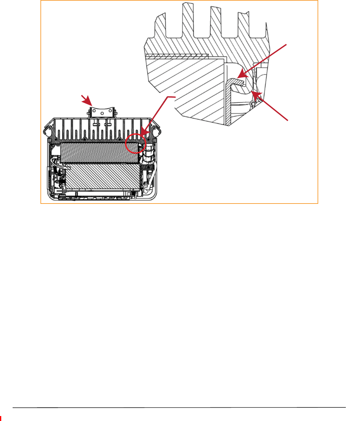
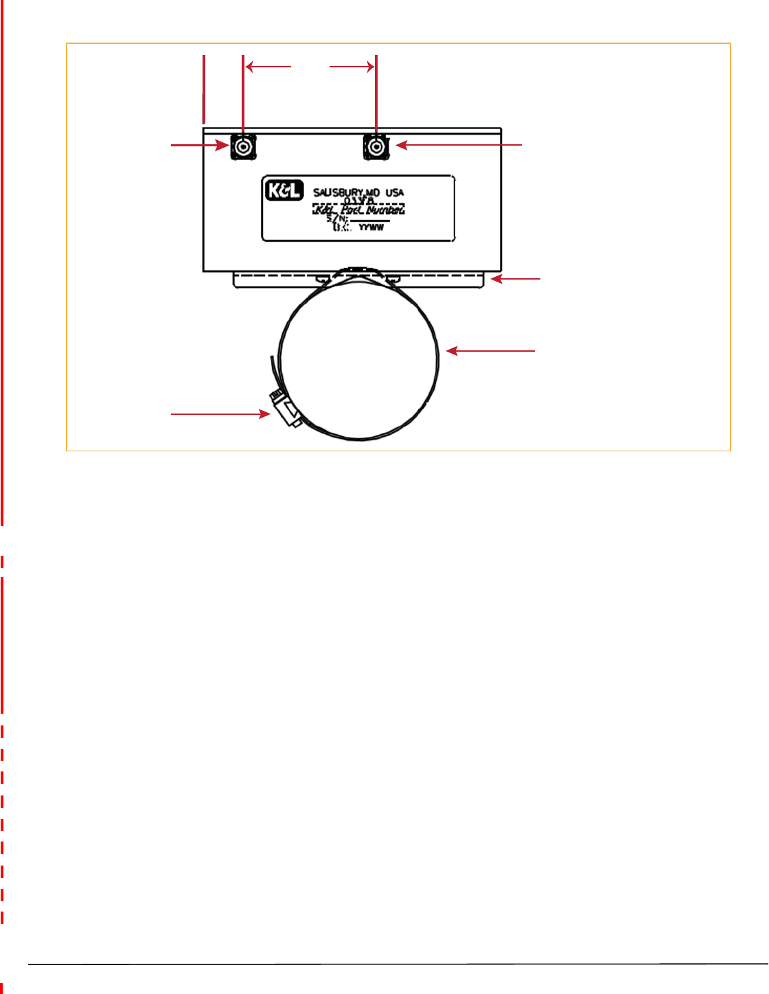
RF MODULE COMPONENTS
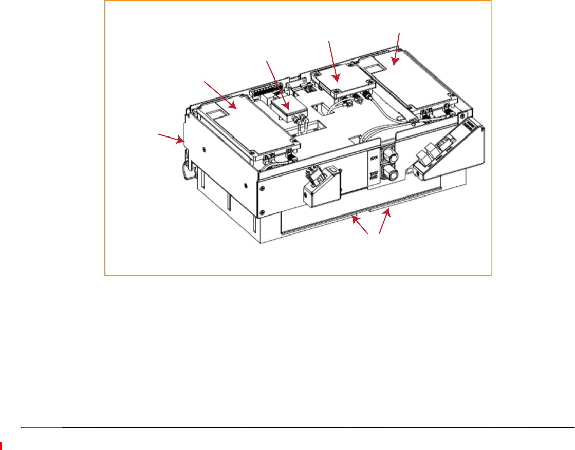
Figure 5 shows typical RF Module components, using the Single-Bay RF Module as an example.
Mounng
latch
Mounng hook Duplexer Power Amplifier (PA)
DARTs
NOTE: The RDI is internal to the RF Module and is therefore not shown.
LNA
(inside the Duplexer caviy)
Figure 5. Single-Bay RF Module Components
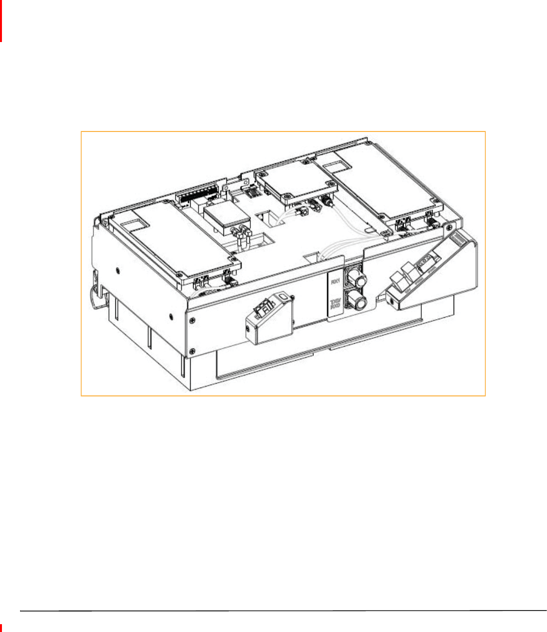
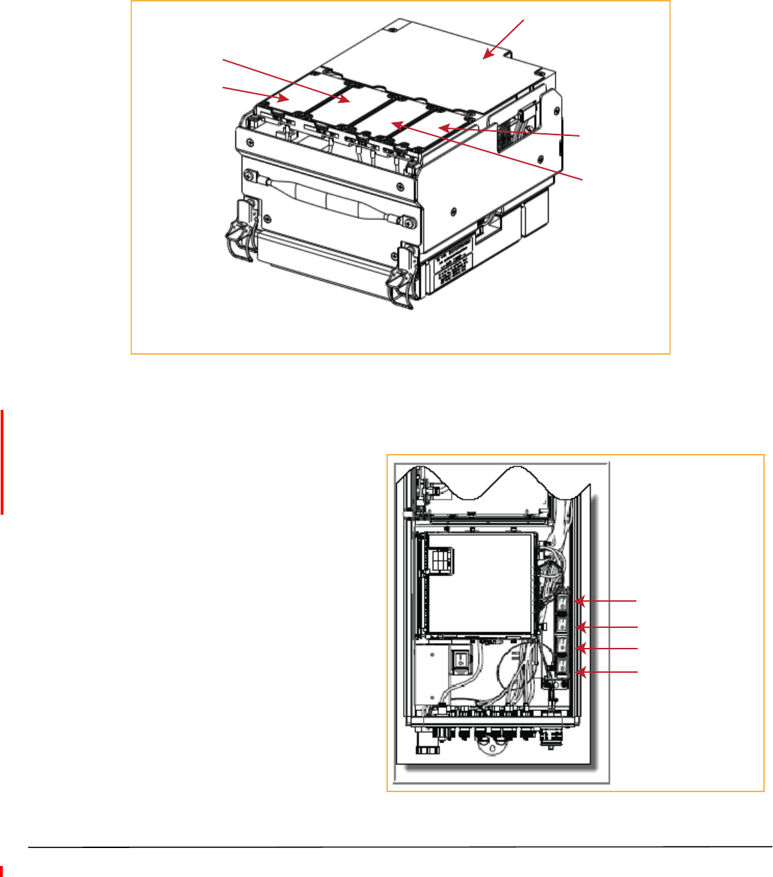
Figure 6 shows the components of an HDM RF Module.
Duplexers Power Amplifier
Mounng latch
Mounng hook
Tx and Rx Cards
DPM
Figure 6. HDM RF Module Components
FlexWave Prism Remote Unit RF Module Installation Guide Page 13
TECP-77-141 Issue 8 • 300001744178 Rev H • August 2015 ©2015 TE Connectivity
Linear Power Amplifiers
The Linear Power Amplifier (LPA) is a high quality broadband RF amplifier used for achieving Prism
product-rated power for the Remote Unit Tx forward path RF. The PAs are pass-band specific, with the maximum
composite Tx power levels listed in Table 8 for Single-Card, Dual-Card, and HDM RF Modules and Table 9 on
page 13 for Legacy Dual-Bay 40W RF Modules.
The LPA is housed within the RF Module, and is not field serviceable.
Table 8. LPA Maximum Composite Tx Power Levels for Single-Card, Dual-Card, and HDM RF Modules
Bandwidth (MHz) supported across entire spectrum
Passband Maximum
dBm Watts
HDM
Single Super DART Classic
DART
Dual
SuperDART
Dual/MIMO SISO
AWS 2100 43 20 39 45 39 NA 45
46 40 NA 45 39 NA 45
Cellular 850 43 20 25 25 NA 25 NA
46 40 25 25 NA 25 NA
EGSM 900 40 10 35 35 35 NA NA
DCS 1800 42 15.8 39 75 39 NA 75
LTE 700 Lower ABC 43 20 18 18 18 NA NA
LTE 700 Upper C 43 20 10 10 10 NA NA
46 40 10 10 10 NA NA
PCS 1900 43 20 39 70 39 NA 70
46 40 39 70 39 NA 70
PGSM 900 40 10 25 25 25 NA NA
SMR 800 43 20 7 7 NA 7NA
SMR 900 38 6.5 NA NA NA 5NA
UMTS 2100 42 15.8 39 60 39 NA 60
2300 WCS 43 20 10 10 10 NA NA
Table 9. LPA Maximum Composite Tx Power Levels for Legacy Dual-Bay 40W RF Modules
Passband Maximum
dBm Watts
Bandwidth (MHz)
supported across
entire spectrum
Classic DART
PCS 1900 +46 40 35
AWS 2100 +46 40 35
NOTE: Industry Canada 20 dB Pass Band Model Number FWP-C4MT000MOD Cellular 850 MHz = 26.3 MHz and
the PCS 1900 = 66.8 MHz.

Page 14 FlexWave Prism Remote Unit RF Module Installation Guide
©2015 TE Connectivity TECP-77-141 Issue 8 • 300001744178 Rev H • August 2015
Duplexer and Low Noise Amplifier
The RF Module provides the Remote Unit with an internal Duplexer that is optimized to provide the desired RF
band-pass filtering and in-band equipment isolation between FWD and REV paths. The Duplexer provides the
filtering necessary to the transmit and receive paths to and from the connected antenna.
The Duplexer for the Single- and Dual-Bay RF Modules and the Legacy Dual-Bay 40W RF Modules contains up to
two REV path Low Noise Amplifiers (LNA for PRI and/or SEC reverse paths).
The Duplexer for an HDM RF Module does not have a Low Noise Amplifier.
Duplexers are not field serviceable.
Digital Processing Module
The Digital Processing Module (DPM) is found only in the HDM RF Modules. The DPM provides the primary
processing and logic functions for the HDM RF Module. It also provides the primary power interface for the HDM
RF Module, and conversion of the native 28 Vdc voltage to lower voltages as necessary for functionality.
The DPM has a Transmit (Tx) Board and a Receive (Rx) Board:
•Tx Board—provides band specific filtering for the intended Transmit path.
•Rx Board—provides band specific filtering for the intended Receive path.
Cables
Always provided at each RF Module shelf are five cables:
•two High-Speed Data Cables, which in this document are referred to as LVDS (Low-Voltage Differential
Signaling) cables
•two RF Cables (TX0/RX0) and (TX1/RX1)
•one Power (PWR) Cable.
The RF Module cables that are pre-installed in the PRU connect to the corresponding connectors on the RF
Module. The RF Module cables correlate to the antenna connectors on the bottom of the Remote Unit chassis.
•
FlexWave Prism Remote Unit RF Module Installation Guide Page 15
TECP-77-141 Issue 8 • 300001744178 Rev H • August 2015 ©2015 TE Connectivity
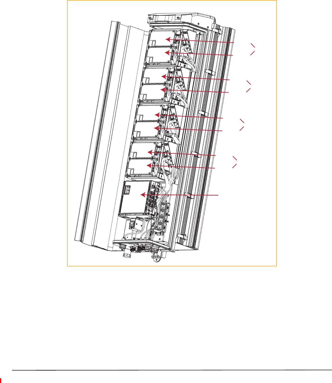
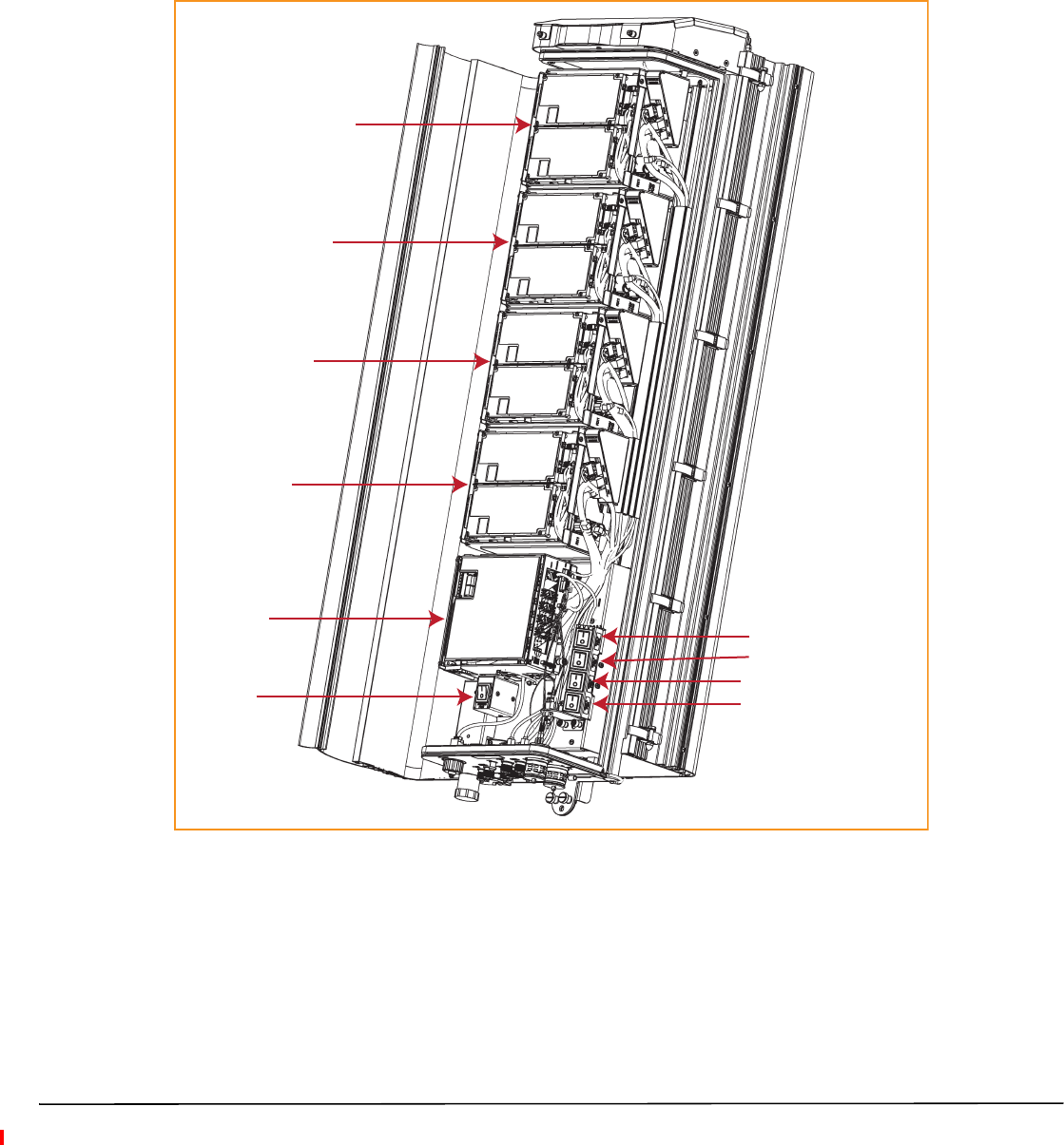
RF GROUP ASSIGNMENTS FOR PRU RF MODULE BAYS
A PRU comprises from one to four RF Module bays. Figure 7 illustrates the numbering of RF Module bays and
DARTs.
Quad-Bay Remote Unit with Single-Card RF Modules
SeRF Module
DART 7
DART 8
Bay D
DART 5
DART 6
Bay C
DART 3
DART 4
Bay B
DART 1
DART 2
Bay A
Figure 7. RF Modules Bays in a PRU

Page 16 FlexWave Prism Remote Unit RF Module Installation Guide
©2015 TE Connectivity TECP-77-141 Issue 8 • 300001744178 Rev H • August 2015
Table 10 lists how the FlexWave Prism EMS references the RF group assignments and corresponding
components of each RF Module.
Table 10. Remote Unit RF Group Assignments (from Top/Down)
Physical RF
Bay
DART
Number
LNA Number LPA
Number
for Single
LPA
LPA
Number for
Dual LPAs
Power
Detector
Number for
Single PD
Power
Detector
Number for
Dual PDs
Primary Diversity
D8 8 7878
7 7 7 7
C6 6 5656
5 5 5 5
B4 4 3434
3 3 3 3
A2 2 1212
1 1 1 1
NOTE: For software releases prior to 7.3, the LPAs were labeled as 1, 2, 3, and 4.
NOTE: For Classic dual position 40W RF Modules only: in a dual LPA system, the Configure Remote Forward
Gain page shows two values for the LPA status, one for each LPA. Changing the LPA Mode or resetting
the LPA applies to both LPAs at the same time.
CAUTION! Should your system experience an LPA problem, refer to Table 10 to ensure that you apply new settings
or troubleshoot the correct RF Module.
The Legacy Dual-Bay 40W RF Module occupies two bays in a PRU. Figure 8 shows the main components in a PRU
enclosure, with a Legacy 40W RF Module occupying Bays A and B. The controlling DART will always be in the
upper bay (B or D), and the second LPA is always in the lower bay (A or C).
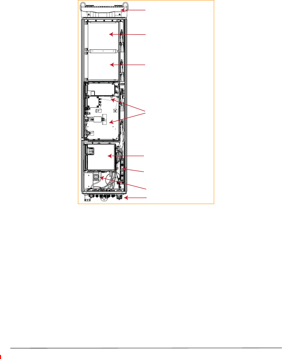
Legacy Dual-Bay 40W RF Module
in Bay B (upper slot) and
Bay A (lower slot) with the
controlling DART in Bay B
AC or DC power switch
Four DC power switches
SeRF Module and Power supplies
Bay C (empty for future use)
Bay D (empty for future use)
Fans
Connecvity panel with Status LED
FlexWave Prism Remote Unit RF Module Installation Guide Page 17
TECP-77-141 Issue 8 • 300001744178 Rev H • August 2015 ©2015 TE Connectivity
Figure 8. Legacy Dual-Bay 40W RF Module in a Quad-Bay PRU
NOTE: If a Legacy Dual-Bay 40W RF Module AWS 2100 and a Legacy Dual-Bay 40W RF Module PCS 1900 are
both installed in a Quad-Bay PRU, it is recommended that the PCS 1900 be installed in upper-most bay,
and the AWS 2100 be installed in the lower-most bay.
NOTE: To accommodate two-bay modules, you need to remove a module bay shelf as described in “Dual-Bay
Modules Only—Remove the Module Bay Shelf” on page 25.

Page 18 FlexWave Prism Remote Unit RF Module Installation Guide
©2015 TE Connectivity TECP-77-141 Issue 8 • 300001744178 Rev H • August 2015
UNDERSTANDING RF CABLE RULES
•When installing a Diversity, MIMO or Dual-Band RF Module, both RF cables labeled MOD N TX0/RX0 and
MOD N TX1/RX1 shall be connected to the N-Style connections of the RF Module. Note that older labeling
schemes used “PRI” and “DIV”. To match old labeling schemes to current labeling:
Old Label New Label
PRI TX0/RX0
DIV TX1/RX1
•When installing a Non-Diversity or SISO RF Module, or an SMR 800/900 Dual-Band Dual-Bay RF Module:
–The MOD N TX0/RX0 cable shall be connected to the single available N-Style RF Connection of the RF
Module.
–The MOD N TX1/RX1 cable shall be constrained to the existing cables using a tie wrap or similarly
accepted fastener so it cannot be pinched or prevent the Remote Unit door from closing. Do not cut or
attempt to otherwise remove this RF Cable.
•RF cables are hand-formable; however, cables must adhere to a minimum bend radius of 1-inch from the
outlet of the integrated cable guide to the respective N-Style RF connection on the RF Module.
RF Module Cables and Supported Bay Use for Single-Card, Dual-Card, and HDM RF Modules
The RF cable and connector labels correspond to the RF Module bays in the Remote Unit chassis, where MOD A
is the bottom bay and MOD D is the top bay.
•The cables and connectors have corresponding labels as shown in Table 11 for Single-Card, Dual-Card, and
HDM RF Modules. For Dual-Bay installations, the RF cables and connectors are labeled as MOD N TX0/RX0 and
MOD N TX1/RX1, where N refers to the top bay of the double-bay installation. For example:
–For a Dual-Bay installation in a Quad-Bay chassis in which the RF Module is installed in the Bay D and Bay
C combination, the RF cables and connectors are labeled as MOD D TX0/RX0 and MOD D TX1/RX1.
–For a Dual-Bay installation in a Tri-Bay chassis in which the RF Module is installed in the Bay B and Bay
A combination, the RF cables and connectors are labeled as MOD B TX0/RX0 and MOD B TX1/RX1.
•Table 11 also shows which RF Module type can be installed in which PRU bay or bay combination.
•The Single-Bay chassis is not included in Table 11.

Table 11. Supported Bay Use and RF Antenna Labels for Single-Card, Dual-Card, and HDM RF Modules
(From Top of Remote Unit Chassis Down)
Supported Bay
Configurations
for Single-Bay
RF Modules
Supported Bay Combinations
for Dual-Bay RF Modules
RF Module
Cable, RF
Module
Connector, and
Remote Antenna
Connector Label
Function
Supported
Bays in
Dual-Bay
Chassis
Supported
Bays in
Tri-Bay
Chassis
Supported
Bays in
Quad-Bay
Chassis
Bay D
MOD D N/A N/A
MOD D
Mod D TX0/RX0 Transmit RF power and primary/Path 1 receive
to/from the antenna for RF Module D
Mod D TX1/RX1 Transmit RF power and secondary/Path 2
receive to/from the antenna for RF Module D
Bay C
MOD C N/A MOD C
Mod C TX0/RX0 Transmit RF power and primary/Path 1 receive
to/from the antenna for RF Module C
Mod C TX1/RX1 Diversity receive/Path 2 for Transmit RF power
and secondary/Path 2 receive to/from the
antenna for RF Module C
Bay B
MOD B
MOD B MOD B MOD B
Mod B TX0/RX0 Transmit RF power and primary/Path 1receive
to/from the antenna for RF Module B
Mod B TX1/RX1 Transmit RF power and secondary/Path 2
receive to/from the antenna for RF Module B
Bay A
MOD A
Mod A TX0/RX0 Transmit RF power and primary/Path 1 receive
to/from the antenna for RF Module A
Mod A TX1/RX1 Transmit RF power and secondary/Path 2
receive to/from the antenna for RF Module A
FlexWave Prism Remote Unit RF Module Installation Guide Page 19
TECP-77-141 Issue 8 • 300001744178 Rev H • August 2015 ©2015 TE Connectivity

Page 20 FlexWave Prism Remote Unit RF Module Installation Guide
©2015 TE Connectivity TECP-77-141 Issue 8 • 300001744178 Rev H • August 2015
RF Module Cables and Supported Bay Installations for Legacy Dual-Bay 40W RF Modules
The cables and connectors have corresponding labels as shown in Table 12 for Legacy Dual-Bay 40W RF Modules.
Table 12 also shows which RF Module type can be installed in which PRU bay(s) when a 40W Dual-Bay RF Module
is part of the RF Module mix in a PRU chassis. The Single-Bay chassis is not included in Table 12.
For Dual-Bay installations, the RF cables and connectors are labeled as MOD N TX0/RX0 and MOD N TX1/RX1,
where N refers to the top bay of the double-bay installation. For example:
•For a Dual-Bay installation in a Quad-Bay chassis in which the RF Module is installed in the Bay D and Bay C
combination, the RF cables and connectors are labeled as MOD D TX0/RX0 and MOD D TX1/RX1.
•For a Dual-Bay installation in a Tri-Bay chassis in which the RF Module is installed in the Bay C and Bay B
combination, the RF cables and connectors are labeled as MOD C TX0/RX0 and MOD C TX1/RX1.
Table 12. Supported Bay Assignments and RF Antenna Labels for Legacy Dual-Bay 40W RF Modules
(From Top of Remote Unit Chassis Down)
Supported Bay Combinations for Legacy 40W Dual-Bay RF Modules RF Module
Cable,
RF Module
Connector, and
Remote Antenna
Connector Label
Function
Dual-Bay Tri-Bay Tri-Bay Quad-Bay
Bay D
N/A N/A N/A
MOD D
MOD D
MOD C
Mod D TX0/RX0 Transmit RF power and
primary/Path 1 receive to/from
the antenna for RF Module D
Mod D TX1/RX1 Transmit RF power and
secondary/Path 2 receive
to/from the antenna for RF
Module D
Bay C
N/A MOD C
MOD C
MOD C
Mod C TX0/RX0 Transmit RF power and
primary/Path 1 receive to/from
the antenna for RF Module C
Mod C TX1/RX1 Transmit RF power and
secondary/Path 2 receive
to/from the antenna for RF
Module C
Bay B
MOD B MOD B MOD B MOD B
MOD B
Mod B TX0/RX0 Transmit RF power and
primary/Path 1receive to/from
the antenna for RF Module B
Mod B TX1/RX1 Transmit RF power and
secondary/Path 2 receive
to/from the antenna for RF
Module B
Bay A
MOD A MOD A
Mod A TX0/RX0 Transmit RF power and
primary/Path 1 receive to/from
the antenna for RF Module A
Mod A TX1/RX1 Transmit RF power and
secondary/Path 2 receive
to/from the antenna for RF
Module A
Note: For Dual Module installations the center module shelf needs to be removed; see “Dual-Bay Modules Only—Remove the Module Bay
Shelf” on page 25.
Note: Install the Legacy Dual-Bay 40W RF Module in the lower-most bay in the chassis. If, however, if two Legacy Dual-Bay 40W RF Modules
are present, install the 2100 Module in the lower-most Bay and the 1900 Module in the upper-most Bay.

FlexWave Prism Remote Unit RF Module Installation Guide Page 21
TECP-77-141 Issue 8 • 300001744178 Rev H • August 2015 ©2015 TE Connectivity
INSTALL THE RF MODULE(S)
The following sections guide you through the installation of an RF Module into a Remote Unit chassis. The process
to install the four different types of RF Modules is basically the same; however, differences are noted and should
be followed.
NOTE: In the following steps, the RF cables and connectors are referred to as MOD N TX0/RX0 and as MOD N
TX1/RX1 where N equals A, B, C, or D.
NOTE: When installing RF Modules, populate the RF Modules from highest frequency band to lowest within the
Remote Unit chassis. Likewise for power output, populate from the bottom bay to the top; higher
output to lower output. That is, for a deployment with 2100 40W, 1900 40W, 850 20W and 700 20W
MIMO, install the RF Modules as follows:
• 2100 40W RF Module in Bay A
• 1900 40W RF Module in Bay B
• 850 20W RF Module in Bay C
• 700 20W MIMO RF Module in Bay D.
Safety Precautions
CAUTION! This is restricted access equipment and only qualified service personnel should service and operate this
equipment using appropriate tools.
CAUTION! Wet conditions increase the potential for receiving an electrical shock when installing or using
electrically-powered equipment. To prevent electrical shock, never install or use electrical equipment
in a wet location or during a lightning storm.
CAUTION! Always allow sufficient fiber length to permit routing of patch cords and pigtails without severe bends.
Fiber optic patch cords or pigtails may be permanently damaged if bent or curved to a radius of less than
2 inches (5.1 cm).
CAUTION! Exterior surfaces of the Prism Remote Unit may be hot. Use caution during servicing.
CAUTION! Service personnel must confirm that the perimeter gasket and door-to-door gaskets are in place when
closing the Remote Unit doors after servicing.
CAUTION! This equipment uses a Class 1 Laser according to FDA/CDRH rules. Laser radiation can seriously damage
the retina of the eye. Do not look into the ends of any optical fiber. Do not look directly into the optical
transceiver of any digital unit or exposure to laser radiation may result. An optical power meter should
be used to verify active fibers. A protective cap or hood MUST be immediately placed over any radiating
transceiver or optical fiber connector to avoid the potential of dangerous amounts of radiation
exposure. This practice also prevents dirt particles from entering the adapter or connector.
CAUTION! This system is an RF Transmitter and continuously emits RF energy. Maintain 3 foot (91.4 cm) minimum
clearance from the antenna while the system is operating. Wherever possible, shut down the RAN
before servicing the antenna.

Page 22 FlexWave Prism Remote Unit RF Module Installation Guide
©2015 TE Connectivity TECP-77-141 Issue 8 • 300001744178 Rev H • August 2015
Guard against Damage from Electro-Static Discharge
CAUTION! Electro-Static Discharge (ESD) can damage electronic components. To prevent ESD damage, always wear
an ESD wrist strap when working with a Prism Remote Unit or when handling any of its
components—including the RF Modules. Connect the ground wire on the ESD wrist strap to an earth
ground source before touching the Prism Remote Unit or any of its components. Wear the wrist strap
the entire time that you work with the Prism Remote Unit and its components.
CAUTION! Place Prism RF Modules in anti-static packing material when transporting or storing them.
Unpack and Inspect the RF Module
1Inspect the exterior of the shipping container(s) for evidence of rough handling that may have damaged the
components in the container.
2Unpack each container while carefully checking the contents for damage and verify with the packing slip.
3If damage is found or parts are missing, file a claim with the commercial carrier and notify TE Customer
Service (see “Contacting TE Connectivity” on page 51). Save the damaged cartons for inspection by the carrier.
4Save all shipping containers for use if the equipment requires shipment at a future date.
CAUTION! Handle the RF Module with care during installation. Be especially careful to not damage the
thermal-interface material (TIM), which is attached to the LPA, DARTs, and/or Motherboard with TX/RX
boards. If the TIM is damaged, the LPA can overheat. Before installing the RF Module, check to see if the
heatsink material is gouged or cracked. If the TIM is damaged, do not install the RF Module and contact
TE Connectivity for assistance (see “Contacting TE Connectivity” on page 51 for contact information).
CAUTION! If the thermal-interface material is damaged, the installation and use of the RF Module may void the
warranty of the RF Module.
FlexWave Prism Remote Unit RF Module Installation Guide Page 23
TECP-77-141 Issue 8 • 300001744178 Rev H • August 2015 ©2015 TE Connectivity
Remove Release Liners from the RF Module
NOTE: Release Liners are present on front and back of new modules.
1Open the Remote Unit enclosure.
2Remove release liners, if present, from the thermal pads on the RF Module prior to installing the module into
the Remote Unit chassis.
CAUTION! The thermal pads are very sensitive to mishandling—do not nick, scratch, or ding them.
For Single- and Dual-Bay RF Modules, the thermal pads are located as listed below and as shown in Figure 9,
which shows a Legacy Dual-Bay 40W RF Module.
•one large pad on the back surface of each Linear Power Amplifier (LPA)
•up to two on the front surface (DARTs)
•one on the left side for the (RDI)
•one on the vector modulator board
One large
thermal pad on each PA
(boom of the LPA)
One thermal pad
for the RDI
One thermal pad
for each DART
One thermal pad
for each DART
One thermal pad
for RF Power
Combiner
One thermal pad
for Vector
Modulator
•one on the RF power combiner.
Figure 9. Thermal Pads on a Legacy Dual-Bay 40W RF Module
Page 24 FlexWave Prism Remote Unit RF Module Installation Guide
©2015 TE Connectivity TECP-77-141 Issue 8 • 300001744178 Rev H • August 2015
For HDM RF Modules, the thermal pads are located as listed below and as shown in Figure 10.
•one pad for each Rx and Tx board
•one large pad over the DPM
•one for each Power Amplifier (PA), which is on the bottom of the HDM RF Module.
DPM Thermal Pad
Tx A Thermal Pad
Tx B Thermal Pad
Rx A Thermal Pad
Rx B Thermal Pad
2.9796 in2.9796 in
NOTE: Tx and Rx cards are paired: Tx A ony pairs with Rx A and Tx B only pairs with Rx B.
Figure 10. Thermal Pads on an HDM RF Module
Check the DC Power Switch for the Module Bay
DC Power switch for Bay A
DC Power switch for Bay B
DC Power switch for Bay C
DC Power switch for Bay D
Ensure that the DC power switch that
corresponds to the bay(s) in which the RF Module
is to be installed is in the Off position (see graphic
to the right).
FlexWave Prism Remote Unit RF Module Installation Guide Page 25
TECP-77-141 Issue 8 • 300001744178 Rev H • August 2015 ©2015 TE Connectivity
Dual-Bay Modules Only—Remove the Module Bay Shelf
1
Use 9/64” Allen Wrench to
remove the three module-shelf screws
Remove Module D Shelf for
Dual-Band Dual-Slot RF Modules
Remove Module B Shelf for
Dual-Slot 40W RF Modules
FOR DUAL-BAY RF MODULES ONLY.
If you are installing a Dual-Bay RF Module, you
must remove a module bay shelf from the PRU
chassis to accommodate the module’s size.
(For further information, see Table 11 on
page 19.)
Remove the shelf as appropriate for the RF
Module:
•When installing in the A and B Bays,
remove the Module B Bay Shelf.
•When installing in the C and D Bays,
remove Module D Bay Shelf.
To remove a Module Bay Shelf:
aUse a 9/64” Allen™ wrench to remove the
three screws that attach the module shelf
to the PRU chassis, as shown in the
following graphic.
bDiscard or store the module shelf and
fasteners.
Page 26 FlexWave Prism Remote Unit RF Module Installation Guide
©2015 TE Connectivity TECP-77-141 Issue 8 • 300001744178 Rev H • August 2015
Install the RF Module into the Prism Remote Chassis
1Hold the RF Module so that the DART card(s) face away from the PRU and the Mounting Hook is toward the
Receiving flange on the PRU chassis.
NOTE: Always install RF Modules from the bottom up. Do not skip a bay, as this provides more efficient heat
dissipation.
2Holding the RF Module at a 45° angle in respect to the rear heatsink, rest the bottom surface of the module
on the RF Module shelf, as shown in one of the following graphics, and as applicable to the RF Module.
•Single-Bay RF Module: Figure 11 on page 26
•HDM RF Module: Figure 12 on page 27
•Dual-Bay RF Module: Figure 13 on Page 28
•Legacy Dual-Bay 40W RF Module: Figure 14 on Page 29.
Bay C
Bay D
SeRF
Module
Bay A
Bay B
Single-Slot
RF Module
Heat Sink
Figure 11. Installing a Single-Bay RF Module
Bay C
Bay D
SeRF Module
Bay A
Bay B
HDM RF Module
FlexWave Prism Remote Unit RF Module Installation Guide Page 27
TECP-77-141 Issue 8 • 300001744178 Rev H • August 2015 ©2015 TE Connectivity
Figure 12. Installing an HDM RF Module
Installing a Dual-Band
Dual-Slot RF Module
Page 28 FlexWave Prism Remote Unit RF Module Installation Guide
©2015 TE Connectivity TECP-77-141 Issue 8 • 300001744178 Rev H • August 2015
Figure 13. Installing a Dual-Bay RF Module
FlexWave Prism Remote Unit RF Module Installation Guide Page 29
TECP-77-141 Issue 8 • 300001744178 Rev H • August 2015 ©2015 TE Connectivity
Figure 14. Installing a Legacy Dual-Bay 40W RF Module
Page 30 FlexWave Prism Remote Unit RF Module Installation Guide
©2015 TE Connectivity TECP-77-141 Issue 8 • 300001744178 Rev H • August 2015
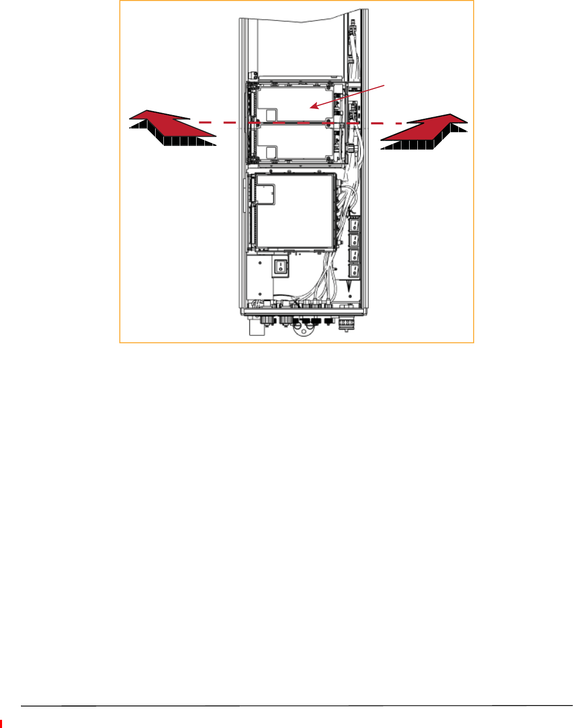
3Align the Mounting Hook on the module with the receiving flange on the PRU heat sink, and then slide the RF
Module in toward the flange until it can go no further.
RF Module
Mounng
hook
Chassis
Receiving
flange
Mounng Bracket at
back of the PRU
(View is looking down into the
PRU chassis from the top.)
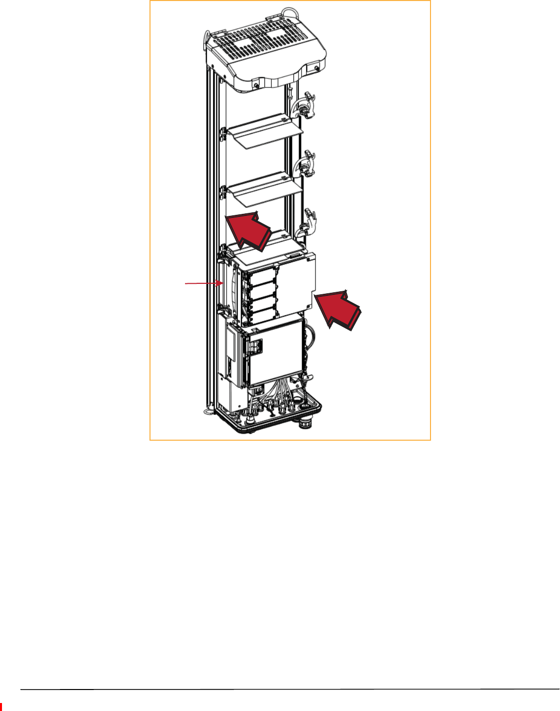
4Push the left edge of the RF Module back and into the PRU chassis until it can go no further, as shown in the
following graphics:
•For Single-Bay RF Modules, see Figure 15 on page 31.
•For HDM RF Modules, see Figure 16 on page 32.
•For Dual-Bay RF Modules, see Figure 17 on page 33, which uses the Legacy Dual-Bay 40W RF Module as
an example.
CAUTION! Make sure the RF Module is seated correctly in the Module shelf. Incorrect alignment of the RF Module
can cause the RF Module to fail due to overheating.
• The front edge of the RF Module should be parallel with the shelf above it.
• The Mounting Hook on the RF Module should be fully engaged with the Receiving flange on the
Remote Unit chassis.
• An incorrectly seated RF Module makes closing the Prism door difficult. If you later cannot shut the
Remote Unit door, verify that the RF Module is installed correctly.
Push the RF Module
back into the chassis
unl it can go no further.
Single-Slot
RF Module
FlexWave Prism Remote Unit RF Module Installation Guide Page 31
TECP-77-141 Issue 8 • 300001744178 Rev H • August 2015 ©2015 TE Connectivity
Figure 15. Seating a Single-Bay RF Module
Push the HDM RF Module
back into the chassis
unl it can go no further.
HDM
RF Module
Page 32 FlexWave Prism Remote Unit RF Module Installation Guide
©2015 TE Connectivity TECP-77-141 Issue 8 • 300001744178 Rev H • August 2015
Figure 16. Seating an HDM RF Module
Push the RF Module back
into the chassis unl it can
go no further.
FlexWave Prism Remote Unit RF Module Installation Guide Page 33
TECP-77-141 Issue 8 • 300001744178 Rev H • August 2015 ©2015 TE Connectivity
Figure 17. Seating a Dual-Bay RF Module
Page 34 FlexWave Prism Remote Unit RF Module Installation Guide
©2015 TE Connectivity TECP-77-141 Issue 8 • 300001744178 Rev H • August 2015
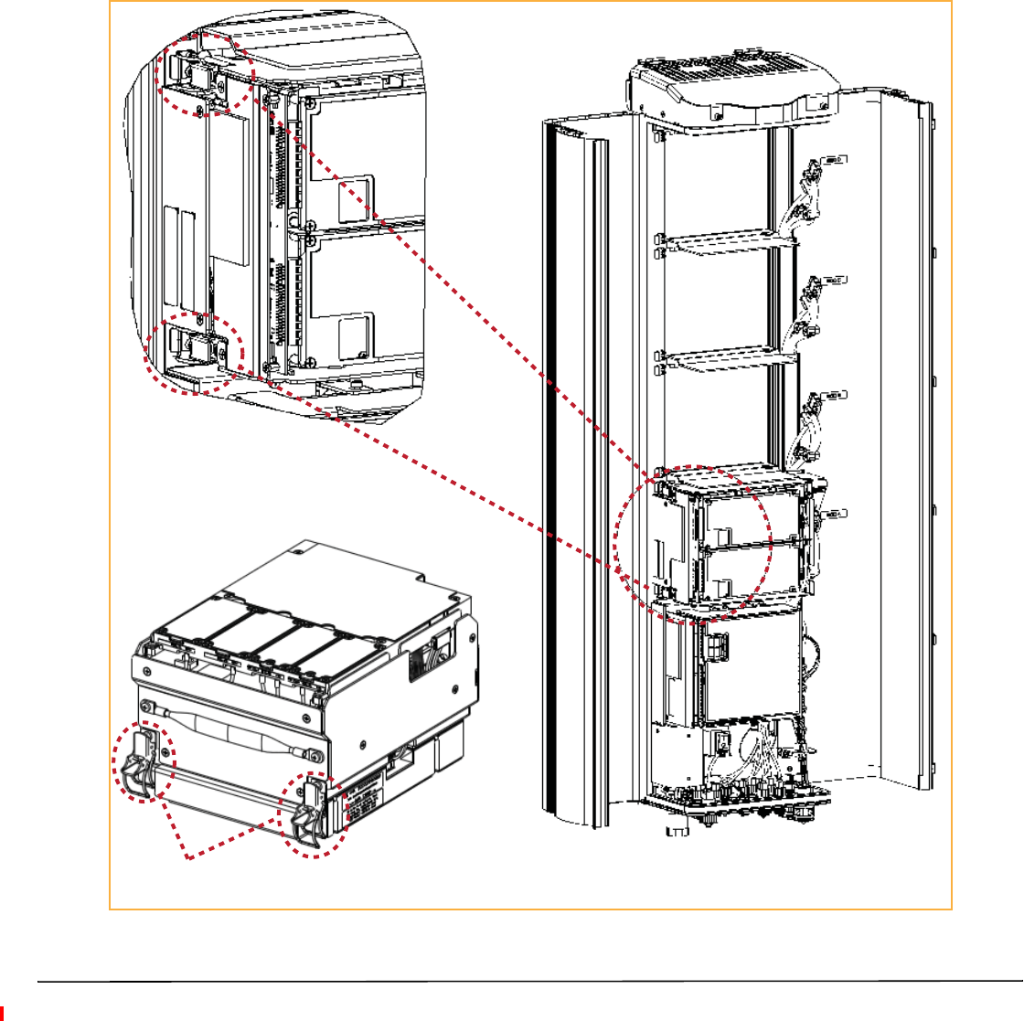
Secure RF Module Latches
1To secure the module latches on the left side of the RF Module, do one of the following, as appropriate for the
RF Module being installed:
•“Connect Latches on Single-Bay and HDM RF Modules” on page 34
•“Connect Latches on Dual-Bay RF Modules” on page 35.
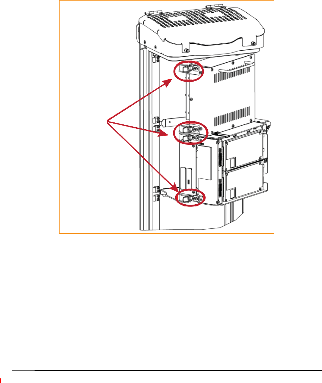
Connect Latches on Single-Bay and HDM RF Modules
For Single-Bay and HDM RF Modules, secure two latches, as shown in Figure 18.
Two latches on Single-Slot
RF Modules
Two latches on
HDM RF Modules
Figure 18. Latches on Single-Bay and HDM RF Modules
FlexWave Prism Remote Unit RF Module Installation Guide Page 35
TECP-77-141 Issue 8 • 300001744178 Rev H • August 2015 ©2015 TE Connectivity
Connect Latches on Dual-Bay RF Modules
For Dual-Bay RF Modules, secure four latches, as shown in Figure 19.
Four latches in a
Dual-Band Dual-Slot
RF Module
Figure 19. Dual-Bay RF Module Latches

Page 36 FlexWave Prism Remote Unit RF Module Installation Guide
©2015 TE Connectivity TECP-77-141 Issue 8 • 300001744178 Rev H • August 2015
Latches on Legacy Dual-Bay 40W RF Modules
For Legacy Dual-Bay 40W RF Modules, secure four latches, as shown in Figure 20.
Four latches in a
Legacy Dual-Slot 40W
RF Module
Figure 20. Legacy Dual-Bay 40W RF Module Latches
Verify that the RF Module Mounting Hook is Engaged
Verify that the RF Module Mounting Hook is engaged correctly by pulling the module away from the heat sink.
The RF Module should not move. If the RF Module moves during this check, repeat all the steps starting at “Install
the RF Module into the Prism Remote Chassis” on page 26 through this step.
Connect the RF Module Cables to the PRU Chassis
The steps to connect the RF Module cables have been separated into two different procedures; follow the steps
that correspond to the RF Module being installed.
•“Connecting Cables in a Single-Bay RF Module Installation” on page 37
•“Connecting Cables in a Dual-Bay RF Module Installation” on page 40.

FlexWave Prism Remote Unit RF Module Installation Guide Page 37
TECP-77-141 Issue 8 • 300001744178 Rev H • August 2015 ©2015 TE Connectivity
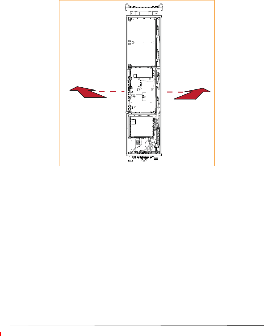
Connecting Cables in a Single-Bay RF Module Installation
1Position the cables so that they are under the right edge of the RF Module, pointing up.
2Follow the rules listed in “Understanding RF Cable Rules” on page 18.
3Connect the RF Module cables, in the order shown below. As you work, refer to the graphic that corresponds
to the RF Module being installed into a single bay of the PRU: for a Single-Bay RF Module, refer to Figure 21
on page 38, and for an HDM RF Module, refer to Figure 22 on page 39 and Table 13 on page 39.
aConnect the MOD N TX0/RX0 cable to the RF Module (the RF cables and connectors are referred to as
MOD N TX0/RX0 where N equals A, B, C, or D).
iInsert the N-Style Plug of the MOD N TX0/RX0 cable into the TX0/RX0 N-Style Jack of the RF Module.
ii Turn the coupling nut of the plug clockwise to thread onto the jack and finger-tighten.
iii Torque coupling nut to 8 ±1 in-lbs to ensure full connection.
NOTE: Insufficient torque applied to RF Module connections can result in elevated insertion/return loss and
higher than normal VSWR reported by the system.
bConnect the MOD N TX1/RX1 cable to the RF Module (the RF cables and connectors are referred to as
MOD N TX1/RX1 where N equals B, C, or D).
iIf a TX1/RX1 RF Module connection is available, insert the N-Style Plug of the MOD N TX1/RX1 cable
into the TX1/RX1 N-Style Jack of the RF Module. If RF Module connection is not available, constrain
the MOD N TX1/RX1 cable to accompanying cables using a tie wrap so it cannot be pinched or prevent
the Remote Unit door from closing.
ii Turn the coupling nut of the plug clockwise to thread onto the jack and finger-tighten.
iii Torque coupling nut to 8 ±1 in-lbs to ensure full connection.
NOTE: Insufficient torque applied to RF Module connections can result in elevated insertion/return loss and
higher than normal VSWR reported by the system.
cConnect the LVDS Cables to the RF Module—the LVDS cables labeled PRIM and DIV should always either
be connected to a RF Module or strain relieved to adjacent cables, as this protects the cable against
damage through misplacement. Maintain adequate strain-relief distances from the connection points to
the RF Module.
iConnect the MOD N DIV LVDS Cable to the DIV receptacle of the RF Module by inserting and sliding
in until fully seated. Full insertion can be recognized by an audible click as the LVDS Cable Connector
locks into the RF Module Receptacle.
ii Connect the MOD N PRIM LVDS Cable to the PRIM connector, following the same steps as above. Full
insertion can be recognized by an audible click as the LVDS Cable Connector locks into the RF Module
Receptacle.
iii Ensure the two LVDS cables are fully seated and latched into their respective receptacles on the RF
Module by lightly pulling outward on the connectors. If fully seated and locked into position, the cable
connectors will not slide back out.
Page 38 FlexWave Prism Remote Unit RF Module Installation Guide
©2015 TE Connectivity TECP-77-141 Issue 8 • 300001744178 Rev H • August 2015
dConnect the Power cable to the PWR receptacle of the RF Module.
iEnsure that the DC power switch that corresponds to the bay(s) in which the RF Module is to be
installed is in the Off position (see “Check the DC Power Switch for the Module Bay” on page 24).
iInsert the Power cable into the PWR connector, and slide it in until fully seated. Full insertion can be
recognized by an audible click as the Power cable Connector locks into the RF Module Receptacle.
ii Verify that the Power cable is fully seated by lightly pulling back on it while making sure to not
depress the release triggers on the ends of the connector. When fully inserted, the cable should not
be able to be removed from the receptacle.
4Repeat all the steps in “Install the RF Module(s)” on page 21 to install other RF Modules.
Bay A
Bay D
Bay C
Bay B
SeRF
Module
TX0/RX0
TX1/RX1
DIV
PRIM
PWR
Note roung of
high-speed cables
Note bend
radii ≥ 1-inch
Edge of Connector Interface Panel
Cable connecons for a Single-Slot RF Module
Figure 21. Cable Connections for Single-Bay RF Modules
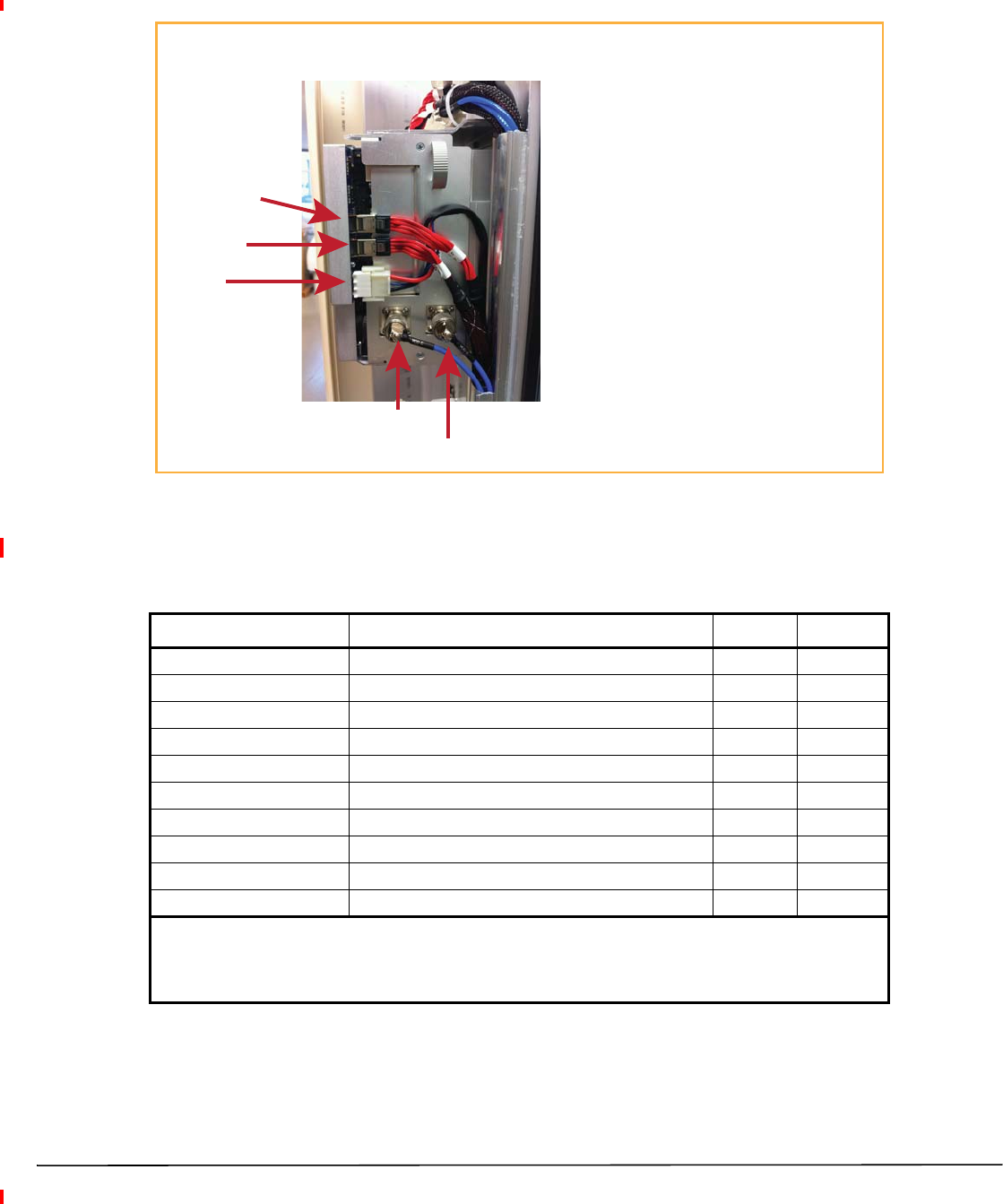
Cable Connecons for an HDM RF Module
TX0/RX0
TX1/RX1
POWER
DATA 1 (DIV)
DATA 0 (PRIM)
Cable Connecon Notes
• Always connect the Power cable.
• Always connect the two LVDS cables: PRIM and DIV.
• SISO requires one RF cable (TX0/RX0).
• MIMO and Dual-Band require two RF cables
(TX1/RX1 and TX0/RX0).
FlexWave Prism Remote Unit RF Module Installation Guide Page 39
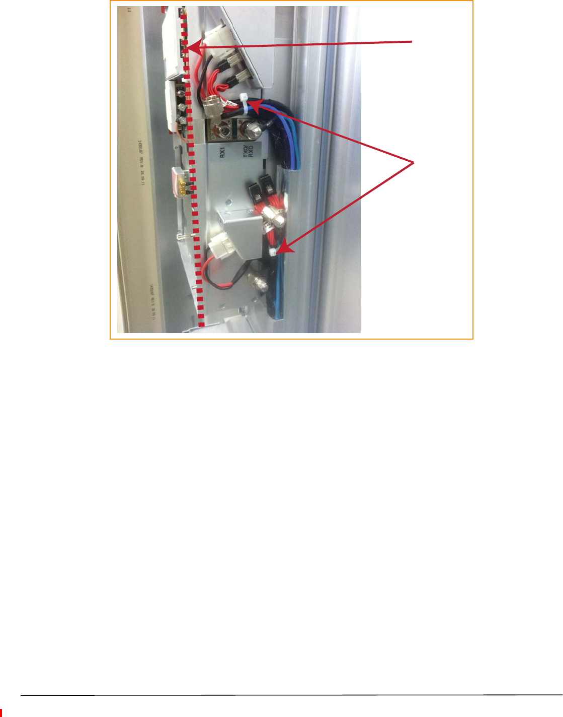
TECP-77-141 Issue 8 • 300001744178 Rev H • August 2015 ©2015 TE Connectivity
CAUTION! Ensure that all cable bends are below the top edge of the Connector Interface Panel as indicated by the
dashed line in the preceding figure. Failure to correctly position the cables could inhibit closing the
Remote Unit door, which can result in damage to the cables.
Figure 22. Cable Connections for HDM RF Modules
Table 13 lists how to correctly connect HDM RF Modules to the Antenna ports on the bottom of the Remote Unit.
Table 13. HDM Antenna Port Mapping
RF Module Catalog # Description TX0/RX0 TX1/RX1
20W 700 lABC Module, MIMO HDM, Single-Bay Path 1 Path 2
20W 700 uC Module, MIMO HDM, Single-Bay Path 1 Path 2
20W 700 lABC/700uC, Dual, Single-Bay 700 lABC 700 uC
20W 800 MIMO, Single Bay, with two External Filters Path 1 Path 2
20W 800 SMR/ 1900 PCS, Dual RF Module 1900 800
20W 850 DUAL, MIMO, Single Bay Path 1 Path 2
20W 850 Cell/1900 PCS, Dual, Single-Bay 1900 850
20W 1900 PCS Dual MIMO, Single-Bay Path 1 Path 2
20W 1900/2100 Dual, Single Bay 2100 1900
20W HDM AWS Band 4 MIMO, Single-Bay Path 1 Path 2
(1) A 20W 800 SMR/ 1900 PCS, Dual RF Module RF Module (FWP-441T841MOD) requires a FlexWave Notch
Filter (FWP-SPRINTFILTER) between the Remote Unit and the antenna to provide protection from spurious
emissions in the Public Safety band below 861.35 MHz and the Cellular band above 869.5 MHz. Information
on how to install the Notch Filter is provided in “FlexWave Notch Filter (FWP-SPRINTFILTER)” on page 47.
FWP-L4MT000MOD
FWP-U4MT000MOD
FWP-L4MTU4MMOD
FWP-44MT000MOD
FWP-441T841MOD (1)
FWP-B4MT000MOD
FWP-C4MT000MOD
FWP-84MT000MOD
FWP-84MTA4MMOD
FWP-A4MT000MOD

Page 40 FlexWave Prism Remote Unit RF Module Installation Guide
©2015 TE Connectivity TECP-77-141 Issue 8 • 300001744178 Rev H • August 2015
Connecting Cables in a Dual-Bay RF Module Installation
1Position the cables so that they are under the right edge of the RF Module, pointing up.
2Follow the rules listed in “Understanding RF Cable Rules” on page 18.
3Working from the bottom connector up, connect the RF Module cables, as described below. As you work, refer
to the graphic that corresponds to the RF Module being installed in the Dual-Bay: for a Dual-Bay RF Module,
refer to Figure 23 on Page 42, and for a Legacy Dual-Bay 40W RF Module, refer to Figure 24 on Page 43.
aConnect the MOD N TX1/RX1 cable to the N-Style RF connector on the Dual-Bay RF Module (the RF cables
and connectors are referred to as MOD N TX1/RX1 where N equals B, C, or D).
iConstrain the MOD N TX1/RX1 cable of the lower RF Module bay to accompanying cables using a tie
wrap so it cannot be pinched or prevent the Remote Unit door from closing.
ii Connect the MOD N TX1/RX1 cable to the TX1/RX1 N-Style Jack of the upper RF Module Bay.
iii Turn the coupling nut of the plug clockwise to thread onto the jack and finger-tighten.
iv Torque coupling nut to 8 ±1 in-lbs to ensure full connection.
NOTE: Insufficient torque applied to RF Module connections can result in elevated insertion/return loss and
higher than normal VSWR reported by the system.
bConnect the MOD N TX0/RX0 cable to the RF Module (the RF cables and connectors are referred to as
MOD N TX0/RX0 where N equals A, B, C, or D).
iInsert the N-Style Plug of the MOD N TX0/RX0 cable into the TX0/RX0 N-Style Jack of the lower RF
Module bay. If RF Module connection is not available, constrain the MOD N TX0/RX0 cable to
accompanying cables using a tie wrap so it cannot be pinched or prevent the Remote Unit door from
closing.
ii Turn the coupling nut of the plug clockwise to thread onto the jack and finger-tighten.
iii Torque coupling nut to 8 ±1 in-lbs to ensure full connection.
NOTE: Insufficient torque applied to RF Module connections can result in elevated insertion/return loss and
higher than normal VSWR reported by the system.
cConnect the LVDS Cables to the RF Module.
iIf available, connect the MOD N DIV LVDS Cable to the DIV receptacle of the lower RF Module by
inserting and sliding in until fully seated. If DIV receptacle is not available, constrain the MOD N DIV
LVDS Cable to accompanying cables using a tie wrap so it cannot be pinched or prevent the Remote
Unit door from closing. Full insertion can be recognized by an audible click as the LVDS Cable
Connector locks into the RF Module Receptacle.
ii Connect the MOD N DIV LVDS Cable to the DIV receptacle of the upper RF Module by inserting and
sliding in until fully seated. If DIV receptacle is not available, constrain the MOD N DIV LVDS Cable to
accompanying cables using a tie wrap so it cannot be pinched or prevent the Remote Unit door from
closing. Full insertion can be recognized by an audible click as the LVDS Cable Connector locks into
the RF Module Receptacle.

FlexWave Prism Remote Unit RF Module Installation Guide Page 41
TECP-77-141 Issue 8 • 300001744178 Rev H • August 2015 ©2015 TE Connectivity
iii If available, connect the MOD N PRIM LVDS Cable to the PRIM receptacle of the upper RF Module by
inserting and sliding in until fully seated. If DIV receptacle is not available, constrain the N PRIM LVDS
Cable to accompanying cables using a tie wrap so it cannot be pinched or prevent the Remote Unit
door from closing.
iv Ensure the two LVDS cables are fully seated and latched into their respective receptacles on the RF
Module by lightly pulling outward on the connectors. If fully seated and locked into position, the cable
connectors will not slide back out.
dConnect the Power cable to the PWR receptacle of the RF Module.
iEnsure that the DC power switch that corresponds to the bay(s) in which the RF Module is to be
installed is in the Off position (see “Check the DC Power Switch for the Module Bay” on page 24).
ii Insert the Power cable into the PWR receptacle of the lower RF Module bay, and slide it in until fully
seated. Full insertion can be recognized by an audible click as the Power cable Connector locks into
the RF Module Receptacle.
iInsert the Power cable into the PWR receptacle of the upper RF Module bay, and slide it in until fully
seated. Full insertion can be recognized by an audible click as the Power cable Connector locks into
the RF Module Receptacle. If the PWR receptacle is not available, constrain the Power cable to
accompanying cables using a tie wrap so it cannot be pinched or prevent the Remote Unit door from
closing.
ii Verify that the Power cable is fully seated by lightly pulling back on it while making sure to not
depress the release triggers on the ends of the connector. When fully inserted, the cable should not
be able to be removed from the receptacle.
4Repeat all the steps in “Install the RF Module(s)” on page 21 to install other RF Modules.
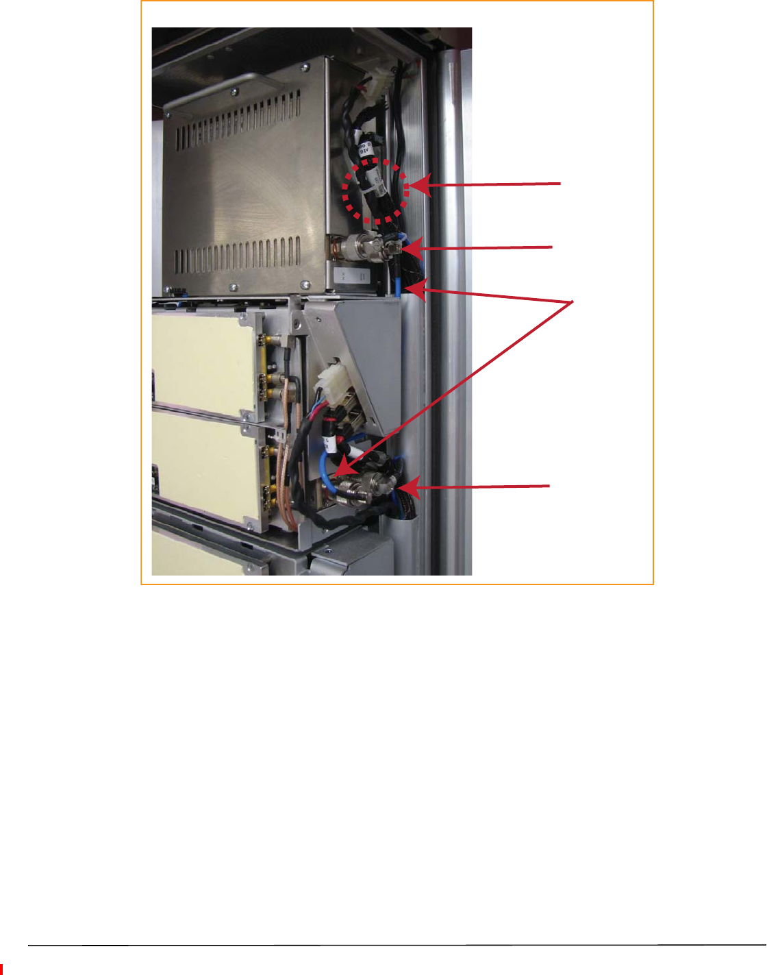
Cable Connecons for a Dual-Slot RF Module
Tie wrap
Factory-installed
RX1 cable
Two N-Type
RF connectors
N-Type
RF connector
Page 42 FlexWave Prism Remote Unit RF Module Installation Guide
©2015 TE Connectivity TECP-77-141 Issue 8 • 300001744178 Rev H • August 2015
Figure 23. Cable Connections for Dual-Band Dual-Bay RF Modules
Tie wrap around
factory-installed
RX1 cable
Keep cable bends
behind the edge
of the Connector
Interface Panel
FlexWave Prism Remote Unit RF Module Installation Guide Page 43
TECP-77-141 Issue 8 • 300001744178 Rev H • August 2015 ©2015 TE Connectivity
Figure 24. Cable Connections for Legacy Dual-Bay 40W RF Modules
CAUTION! Ensure that all cable bends are below the top edge of the Connector Interface Panel as indicated by the
dashed line in the preceding figure. Failure to correctly position the cables could inhibit closing the
Remote Unit door, which can result in damage to the cables.

Page 44 FlexWave Prism Remote Unit RF Module Installation Guide
©2015 TE Connectivity TECP-77-141 Issue 8 • 300001744178 Rev H • August 2015
Power on the RF Module(s) and the Prism Remote Unit
1If necessary, power up the Remote Unit by turning its AC or DC power switch to On.
2Ensure that the external Status LED on the bottom of the Remote Unit goes off.
Boom of an AC-Powered PRU Boom of a DC-Powered PRU
Status LED
NETWORK
POWER
48VDC/XXA
MOD D
TX1/RX1
NETWORK
MOD D
TX1/RX1
POWER
100-240 VAC
50-60 Hz
XX AMPS
WARNING:
HIGH LEAKAGE CURRENT. EARTH
CONNECTION ESSENTIAL BEFORE
CONNECTING SUPPLY
MOD D
TX0/RX0
MOD D
TX0/RX0
NOTE: During bootup, this LED will be red. After approximately one minute, the LED should extinguish.
NOTE: The preceding graphic illustrates the Status LED on a Quad-Bay PRU. The Status LED for the Single-Bay,
Dual-Bay, and Tri-Bay PRUs is in the same location and functions the same as the Status LED for the
Quad-Bay PRU.
FlexWave Prism Remote Unit RF Module Installation Guide Page 45
TECP-77-141 Issue 8 • 300001744178 Rev H • August 2015 ©2015 TE Connectivity
3Follow the rules listed below to toggle the Power switch that corresponds to each RF Module to its ON
position.
•For Dual-Band Dual-Bay RF Modules, use the Power switch for the lower module. For example, to power
up a Dual-Bay RF Module in combined bays C+D in a Quad-Bay chassis, turn ON DC Power switch for Mod
C; leave the DC Power switch for Mod D OFF.
•A Legacy Dual-Bay 40W RF Module uses the Power Supplies in both bays. If the Legacy Dual-Bay 40W RF
Module is installed in bays C+D, turn ON the Power switch for Mod C and Mod D.
Bay A
SeRF
Module
AC/DC Power
switch for
PRU chassis
DC Power switch for Bay A
DC Power switch for Bay B
DC Power switch for Bay C
DC Power switch for Bay D
Bay B
Bay C
Bay D
4Verify that the LEDs for all installed RF Modules (located next to their respective connectors) are green. If any
of the RF Module LEDs are not green, verify that each RF Module cable is seated fully in its respective
connector. If after checking the cable connections and an LED is not green, contact TE for assistance (see
“Contacting TE Connectivity” on page 51).
Page 46 FlexWave Prism Remote Unit RF Module Installation Guide
©2015 TE Connectivity TECP-77-141 Issue 8 • 300001744178 Rev H • August 2015
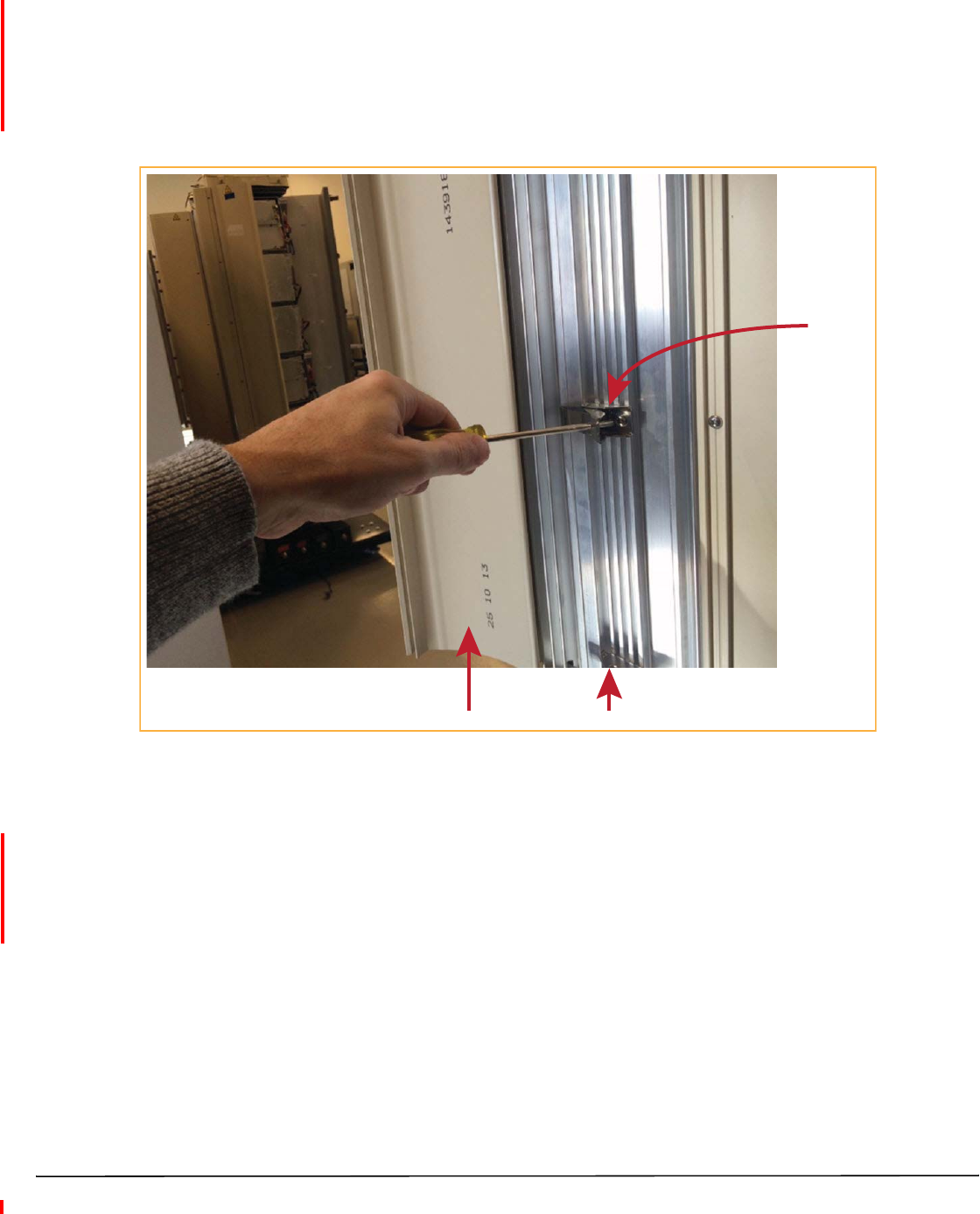
Close the Remote Unit Door and Solar Shield
1Do not slam the door to close it—gently swing the door shut and press it firmly closed.
2Slowly close each door latch in a smooth fluid motion—do not allow the door latches to snap closed. For best
results, starting with the top latch and working down to the bottom latch, use a flat-head screwdriver to close
each latch as shown below.
3Do not slam the Solar Shield to close it—gently swing it shut and press it firmly closed.
Solar Shield Door
Door latch
CAUTION! Service personnel must confirm that the perimeter gasket and door-to-door gaskets are in place when
closing the Remote Unit doors after servicing.
CAUTION! If the PRU door was allowed to snap closed, RF output from an HDM RF Module may be disabled for up
to three minutes. Any alarms generated immediately following the opening/closing of the PRU Doors,
such as Door Open, RF Power Low, System VSWR Fault, and LPA VSWR Fault, automatically clear once
the RF has recovered. If alarms do not clear after three minutes, please contact TE for technical support;
see “Contacting TE Connectivity” on page 51.
Provision the Prism Remote Unit
Refer to the current EMS System Setup and Provisioning Guide for information on configuring the PRU for a
FlexWave Prism system.
FlexWave Prism Remote Unit RF Module Installation Guide Page 47
TECP-77-141 Issue 8 • 300001744178 Rev H • August 2015 ©2015 TE Connectivity
FLEXWAVE NOTCH FILTER (FWP-SPRINTFILTER)
A FlexWave Notch Filter (FWP-SPRINTFILTER) ships with and is required in installations of the following RF
Modules:
•20W 800 SMR/ 1900 PCS, Dual RF Module (FWP-441T841MOD)
•20W 800 MIMO, Single Bay, with two External Filters (FWP-44MT000MOD).
Notch Filter Installation Tips
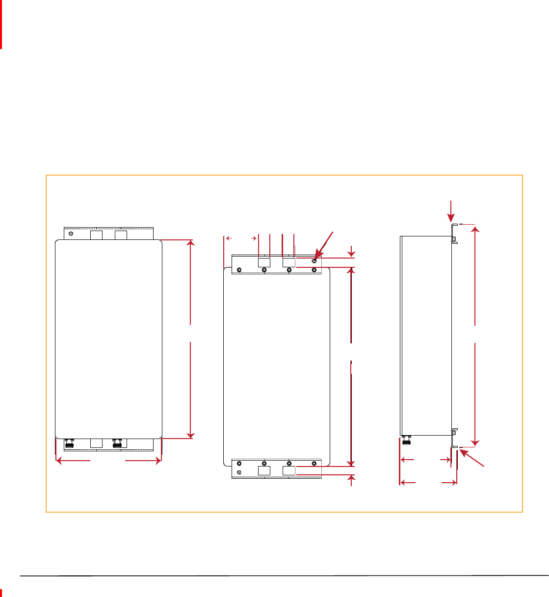
You install the Notch Filter between the Prism Remote Unit and the antenna to provide protection from spurious
emissions in the Public Safety band below 861.35 MHz and the Cellular band above 869.0 MHz.
The following are installation tips for the Notch Filter:
•You can use the same mounting method to mount the Notch Filter as you used to mount the Remote Unit.
•Mount the Notch Filter vertically with the N-type female connectors at the bottom.
•There are two Ground lugs on the Notch Filter, which are on the back of the two mounting brackets. Follow
local practice to ground the Notch Filter.
Figure 25 provides the dimensions required to create a mounting template.
16.0 ±.1
.70
.70
2.805 .95 .95
1.00
2 Locaons
5/16-18
Ground Lug
Front View
Side View
Back View
4.55
17.9 ±.1
4.10 Mounng
Bracket
15.93
8.51
Mounng
Bracket
Figure 25. Notch Filter Mounting Dimensions
Page 48 FlexWave Prism Remote Unit RF Module Installation Guide
©2015 TE Connectivity TECP-77-141 Issue 8 • 300001744178 Rev H • August 2015
Figure 26 illustrates how to pole mount the Notch Filter.
1.13 3.81
Input
N-Type
Female
Connector
Output
N-Type
Female
Connector
Band must be long enough
to wrap around the pole
Boom View of
Notch Filter
Hose clamp sized for
installaon requirement
Mounng Bracket
NOTE: The 800 Notch Filter is
designed to accept input
from the PRU in either its
Output or Input port, as well
as the feed from the antenna.
Figure 26. Pole Mounting a Notch Filter
Notch Filter Specifications
Frequency Range (MHz) Maximum Emissions (Sprint requirement) per 30 kHz
817-824 —
< 854 < -76 dBm
854-859 < -76 dBm
859-861.35 < -76 dBm
861.35-861.5 < -56 dBm
861.5-861.6 < -42 dBm
862-869 —
Enclosure Rating IP67
RF Connectors N-Type Connector, Female (2)
Ground Studs (w/star washer) All ground Studs must accept AWG 6 wire
Mounting Strap mount (Vertical and Horizontal) on up to 12" pole, or Wall mount
Size 15.93" x 8.51" x 4.10"
Weight 18 LBS
Operational Temperature -25°C to +65°C
Humidity ETSI 300-019-1-3 10%-100% Condensing
Vibration-operation ETSI 300-019-1-4
Vibration-transportation ETSI 300-019-1-2

FlexWave Prism Remote Unit RF Module Installation Guide Page 49
TECP-77-141 Issue 8 • 300001744178 Rev H • August 2015 ©2015 TE Connectivity
STANDARDS CERTIFICATION
FCC
This equipment complies with the applicable sections of Title 47 CFR Part 15 (Host Unit), Part 22 (800 MHz Cellular), Part
24 (1900 MHz - PCS), Part 90 (800/900 - SMR), and Part 27 (2100 MHz - AWS, 700 MHz -LTE and 2300 MHz - WCS).
WARNING. This is NOT a CONSUMER device. It is designated for installation by FCC LICENSEES and QUALIFIED
INSTALLERS. You MUST have an FCC LICENSE or express Consent of an FCC Licensee to operate this device. Unauthorized
use may result in Significant forfeiture penalties, including penalties in excess of $100,000 for each continuing violation.
IC
This equipment complies with the applicable sections of RSS-131- Zone Enhancers for the Land Mobile Service. The term
“IC:” before the radio certification number only signifies that Industry Canada Technical Specifications were met.
The Manufacturer's rated output power of this equipment is for single carrier operation. For situations when multiple
carrier signals are present, the rating would have to be reduced by 3.5 dB, especially where the output signal is re-radiated
and can cause interference to adjacent band users. This power reduction is to be by means of input power or gain reduction
and not by an attenuator at the output of the device.
Note: To comply with Maximum Permissible Exposure (MPE) requirements, the maximum composite output from the
antenna cannot exceed 1000 Watts ERP (LTE, Cellular and SMR), the antenna cannot exceed 1640 Watts EIRP (PCS and
AWS), and the antenna must be permanently installed in a fixed location that provides at least 6 meters (20 feet) of
separation from all persons.
UL/CUL
This will be installed in a restricted access location. This equipment complies with Type 4, per UL and CUL 50, Standard for
Enclosures for Electrical Equipment. This equipment provides the degree of protection specified by IPX6 as defined in IEC
Publication 529.
FDA/CDRH
This equipment uses a Class 1 LASER according to FDA/CDRH Rules. This product conforms to all applicable standards of
21 CFR Part 1040.
Caution: Modifications not expressly approved by the party responsible for compliance could void the user's authority to
operate the equipment.
EU Harmonized Standards
Meets essential requirements of R&TTE 1999/5/EC.
•Article 3.1a—The protection of the health and the safety of the user and any other person, including the objectives with
respect to safety requirements contained in Directive 2006/95/EC, but with no voltage limit applying.
•Article 3.1b—The protection requirements with respect to electromagnetic compatibility contained in Directive
2004/108/EC.
•Article 3.2—In addition, radio equipment shall be so constructed that it effectively uses the spectrum allocated to
terrestrial/space radio communication and orbital resources so as to avoid harmful interference.
EMC Standards
EN 55022 and EN55024 (CE marked)
Safety Standards
This equipment complies with IEC 60950-1, 2ND Edition + Amendment 1 (CE marked) and with UL 60950-1, 2ND Edition +
Amendment 1 (File number E174166) (USA and Canada)

Page 50 FlexWave Prism Remote Unit RF Module Installation Guide
©2015 TE Connectivity TECP-77-141 Issue 8 • 300001744178 Rev H • August 2015
ACCESSING USER DOCUMENTATION ON THE TE CUSTOMER PORTAL
You can access additional user documentation on the TE Customer Portal, as described below.
1Click on the following URL link:
https://www.te.com/portal/wireless/
(Alternatively, enter the preceding URL into your web browser, and then press ENTER on your keyboard.)
2Access to the Customer Portal requires a user account and password. On the Sign In page, do one of the
following:
•If you have an account, in the Already Registered? Sign In Now panel, enter your Email and Password, and
then click Sign In.
•If you don’t have an account, under Create an Account, click Register Now and follow the prompts.
3On the Wireless Customer Portal home page, in either the Resources or Documents panel, click the Manuals
and Data Sheets link.
4On the Manuals and Data Sheets page, do the following:
aOpen the folder for the product line that corresponds to the document that you want to access.
bClick on the title of the manual that you wish to open.
c(Optional) Save the PDF to your computer.

FlexWave Prism Remote Unit RF Module Installation Guide Page 51
TECP-77-141 Issue 8 • 300001744178 Rev H • August 2015 ©2015 TE Connectivity
CONTACTING TE CONNECTIVITY
Telephone Numbers
Sales
Asia Pacific +65-6294-9948
France 0800 914032
Germany 0180 2232923
Italy 0800 782374
Spain 900 983291
United Kingdom 0800 960236
USA or Canada 1-800-366-3891
Extension 73000
Connectivity Extension 73475
Wireless Extension 73476
Technical Support
USA or Canada 1-800-530-9960
Elsewhere +1-952-917-0761
Online Access
Customer Portal
https://www.te.com/portal/wireless/
Technical Support for Wireless Products
http://www.te.com/WirelessSupport