ADC Telecommunications PSM25TDH Prism 20W 2.5GHz TDD SISO High HDM User Manual FWPP 504 01
ADC Telecommunications Inc Prism 20W 2.5GHz TDD SISO High HDM FWPP 504 01
Contents
- 1. Installation Instruction
- 2. user manual
- 3. User manual II
User manual II
FWPP-501-01 Issue 1 • 320000117795 Rev A FlexWave Prism Remote Unit and HDM RF Module Installation Guide
© March 2016 CommScope, Inc. Page 61
Install the Prism Remote Unit
Option B: Fiber Pass-Through Connector
NOTE: Use the following procedure to install the fiber cables using a Fiber Pass-Through Connector.
• If the PRU that you are installing has a Hardened Multi-Fiber Optic Connector, follow the
procedure in "Option A: Hardened Multi-Fiber Optic Connector” on page 55
• If the PRU that you are installing has a legacy ProAx Connector, follow the procedure in
"Option C: ProAx Connector (Legacy AC-Powered PRUs)” on page 65.
NOTE: The graphic shown in this procedure depict an AC-powered PRU. However, the Fiber 1 and
Fiber 2 connectors on a DC-powered PRU are in the same location and use the same procedure
as the AC-powered PRU to install fiber cables using a Fiber Pass-Through Connector.
UsethefollowingproceduretoinstallthefibercablesusingtheProAxconnector:
1ObtainanenvironmentallyhardenedfibercableterminatedwithLCconnectors.Theoutside
diameterofthecablejacketmustbebetween.035”and.63”.
2Completetheinstallationstepsin"UnpackandInspectthePrismRemoteUnitandComponents”on
page39through"ConnectaNetworkCabletothePRUChassis”onpage53.
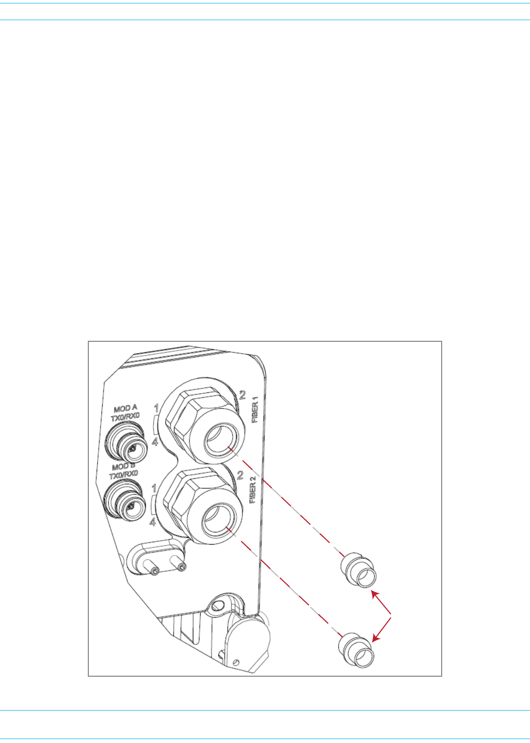
3RemoveconnectorplugonlyfromtheFiber1connector,unlessmultiplefibercablesareneeded.
NOTE: Do not remove the dust cover from the Fiber 2 connector until directed to do so.
Connector
plugs
FlexWave Prism Remote Unit and HDM RF Module Installation Guide 320000117795 Rev A • FWPP-501-01 Issue 1
Page 62 © March 2016 CommScope, Inc.
Install the Prism Remote Unit
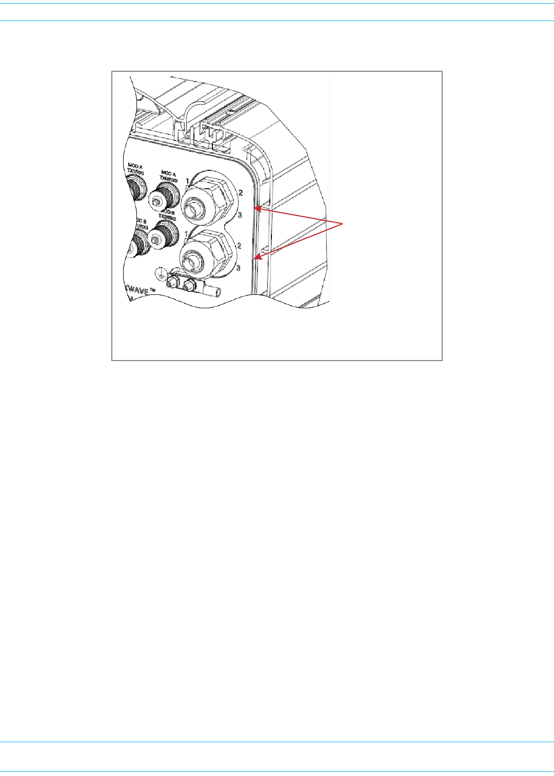
4InserttheFiberOpticcable,terminatedwithLCconnectors,throughtheFiber1Connector.
5CleanallLCconnectorsfollowingindustryapprovedprocedure.
6RefertooneofthefollowinggraphicstoconnecttheLCconnectorstotheSFP:
•forstandardconfigurations,seeFigure15onpage63
•forWDMPass-Throughconfigurations,seeFigure16onpage63.
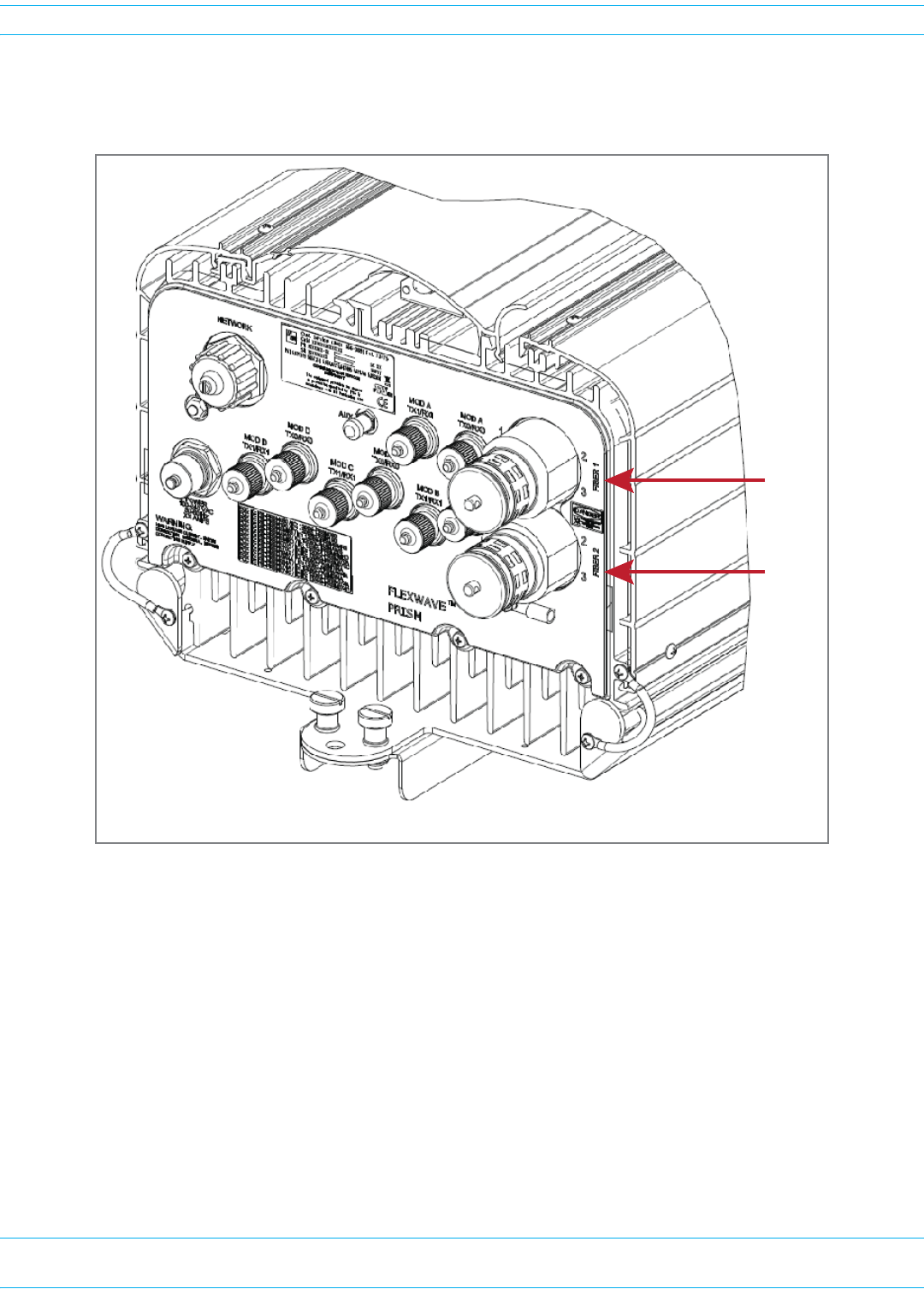
Fiber 1 and Fiber 2 are
Fiber Pass-Through
Connectors
AC or DC PRU
(The Fiber 1 and Fiber 2 connectors are in the same
locaƟon for both the AC- and DC-powered PRUs.)
FIBER 1FIBER 2
FWPP-501-01 Issue 1 • 320000117795 Rev A FlexWave Prism Remote Unit and HDM RF Module Installation Guide
© March 2016 CommScope, Inc. Page 63
Install the Prism Remote Unit
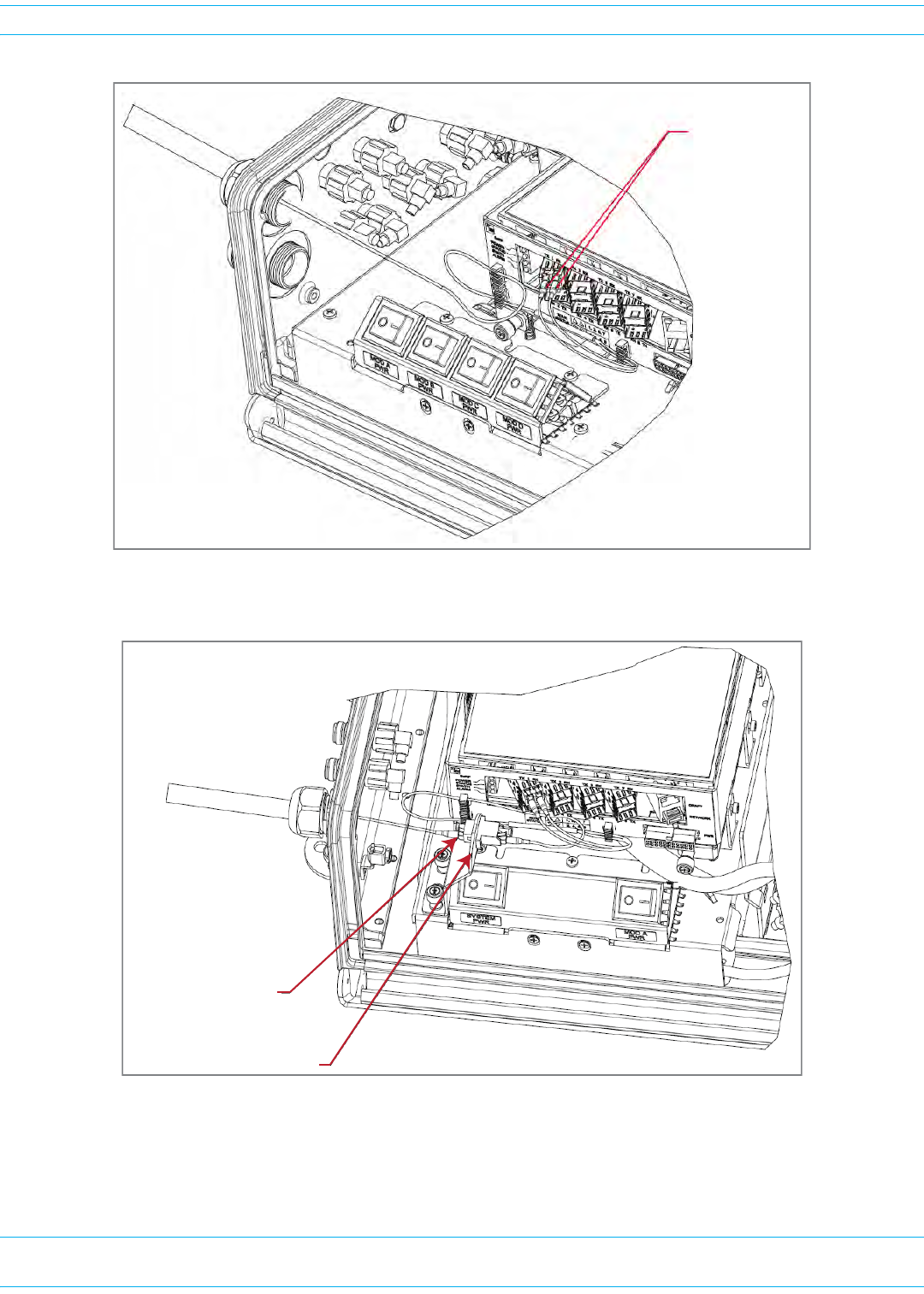
Figure 15. Connect LC Connector to SFP—Standard Configuration
Figure 16. Connect LC Connector to SFP—WDM Pass-Through Configuration
LC connectors
plug into the SFP
Connect a single
LC connector to the
WDM adapter
WDM bracket and adapter
FlexWave Prism Remote Unit and HDM RF Module Installation Guide 320000117795 Rev A • FWPP-501-01 Issue 1
Page 64 © March 2016 CommScope, Inc.
Install the Prism Remote Unit
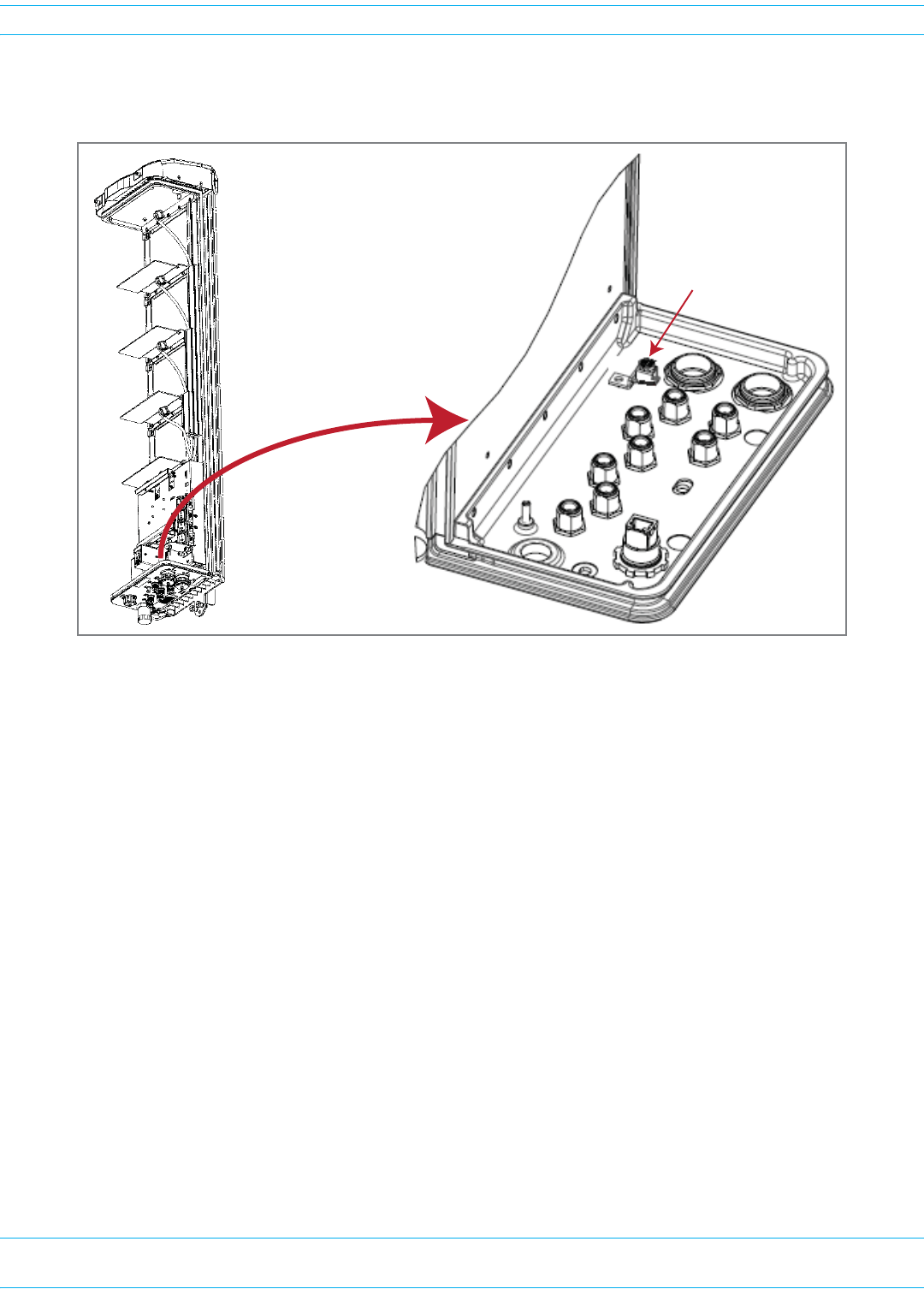
7AttachthestrengthmemberfromtheFiberOpticcabletotheStrain-Relieflugontheinsidebottom
ofthePRU.
8TightentheexternaldomenutofthePass-ThroughConnectoraroundtheFiberOpticcable—torque
thedomenutto44in-lbsplusorminus4in-lbs.
9RoutethefibercablefromtheundersideofthePRUtotheOSPbox.
10 Followlocalpracticestosecurethefibercableinplace.
11 (Optional)OneSFPsupportsupto12timeslotswith75MHzofbandwidth.Ifasecondfibercable
assemblyisrequired(forexample,yourPrismsystemhasthreeSFPstohandleupto280MHzofRF
bandwidth),completeStep3onpage61throughStep10onpage64toaddthesecondfibercable
assembly,onlythistime,connecttotheFiber2connectorlocatedatthebottomofthePRUasshown
inStep4onpage62.
12 Returntothemaininstallationprocessandcontinueat"ConnecttheAntennaCable”onpage69.
Strain-relief lug
FWPP-501-01 Issue 1 • 320000117795 Rev A FlexWave Prism Remote Unit and HDM RF Module Installation Guide
© March 2016 CommScope, Inc. Page 65
Install the Prism Remote Unit
Option C: ProAx Connector (Legacy AC-Powered PRUs)
NOTE: Use the following procedure to install the fiber cables using a legacy ProAx Connector.
• If the PRU that you are installing has a Hardened Multi-Fiber Optic Connector, follow the
procedure in "Option A: Hardened Multi-Fiber Optic Connector” on page 55
• If the PRU that you are installing has a Fiber Pass-Through Connector, follow the procedure
in "Option B: Fiber Pass-Through Connector” on page 61.
NOTE: The ProAx Connector will become obsolete effective 31 May 2013, and will not be used in
PRUs manufactured after 31 May 2013.
NOTE: DC-powered PRUs do not have a ProAx connector option.
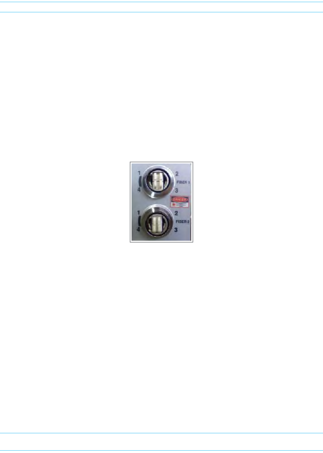
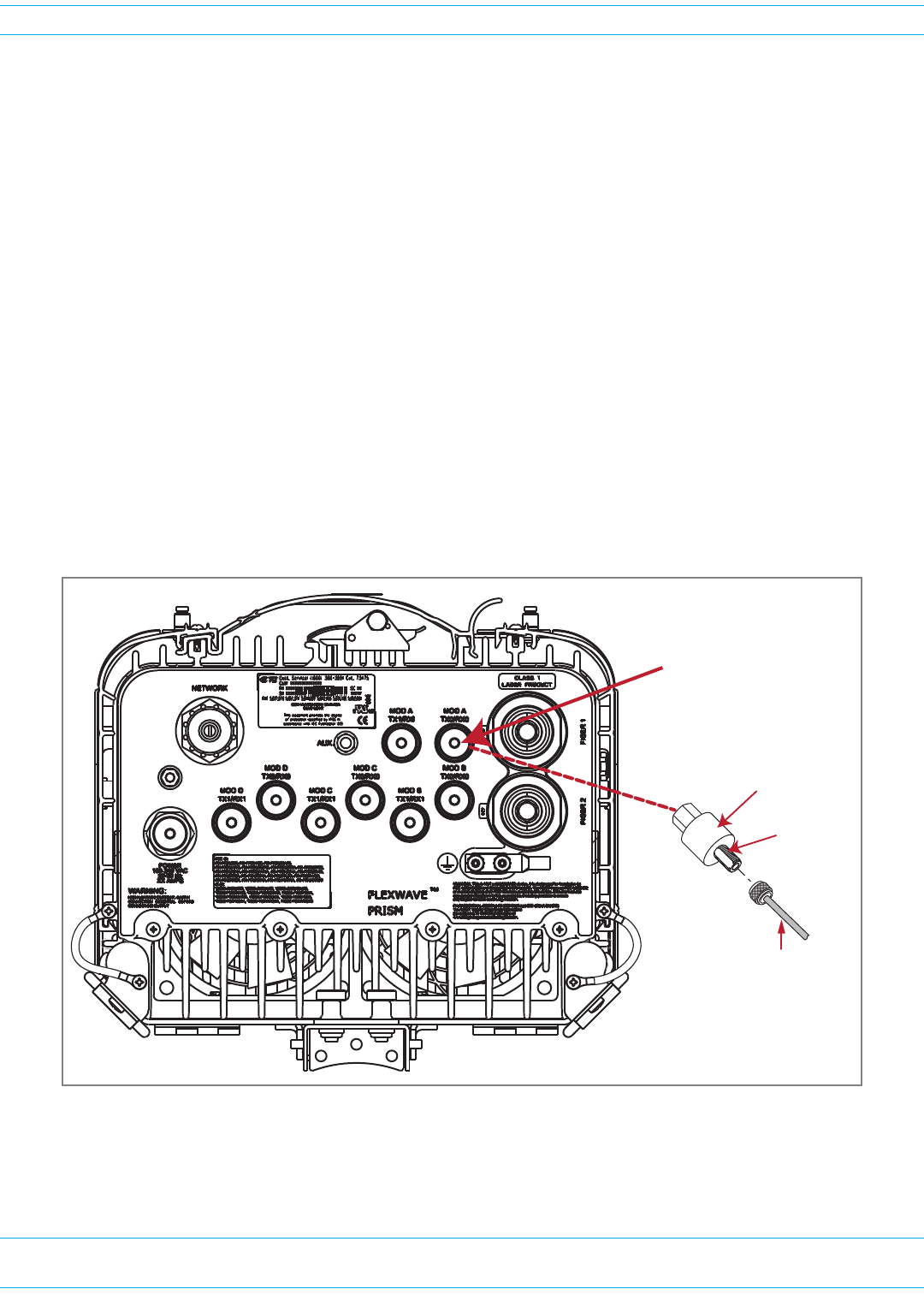
APRUwiththeProAxConnectorconfigurationrequiresthepurchaseofaProAxcableassemblyforthe
PrismtointerfacewiththeOSPfiber.ThefibercableconnectorisaBX.5four-portfiberconnector,as
showninthefollowingpicture:
FlexWave Prism Remote Unit and HDM RF Module Installation Guide 320000117795 Rev A • FWPP-501-01 Issue 1
Page 66 © March 2016 CommScope, Inc.
Install the Prism Remote Unit
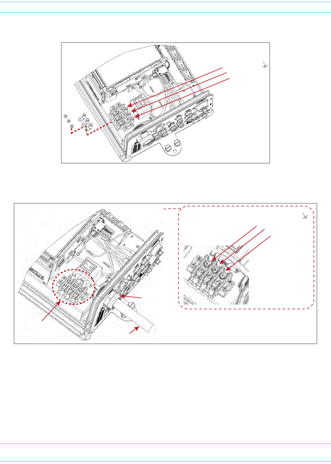
UsethefollowingproceduretoinstallthefibercablesusingtheProAxconnector:
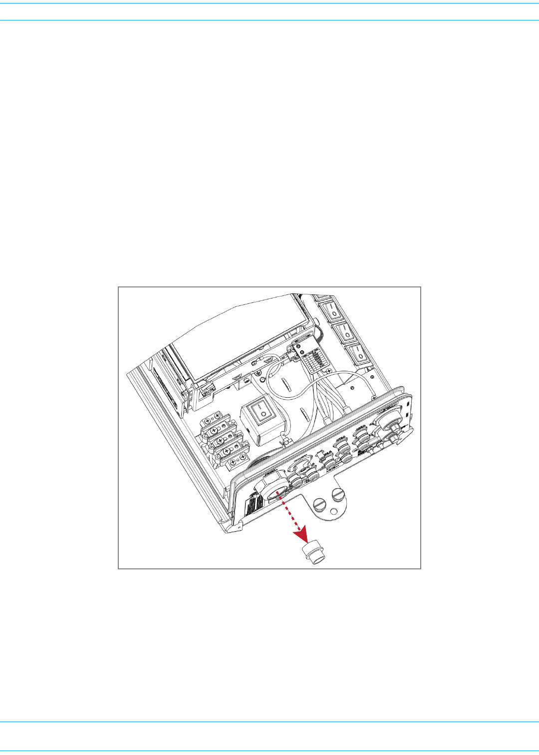
1RemoveProAxconnectordustcoverlocatedatthebottomofthePRU.
Fiber 1
Fiber 2
BoƩom of Quad-Bay PRU with ProAx Connectors
FWPP-501-01 Issue 1 • 320000117795 Rev A FlexWave Prism Remote Unit and HDM RF Module Installation Guide
© March 2016 CommScope, Inc. Page 67
Install the Prism Remote Unit
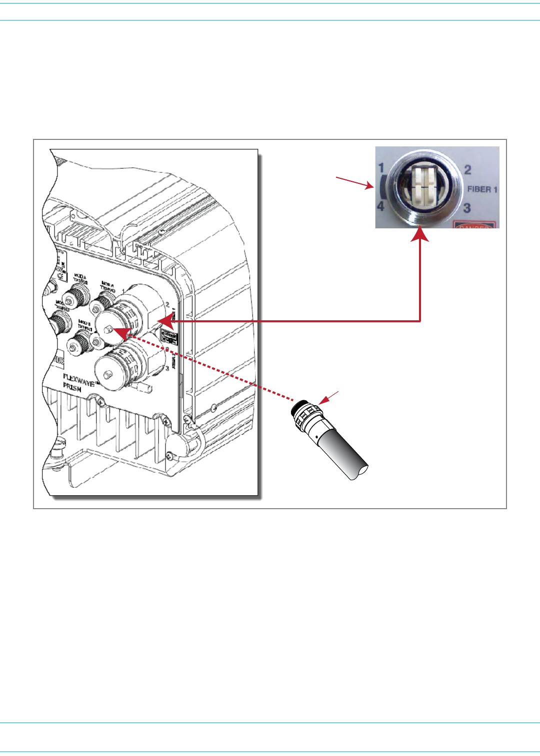
2RemovethedustcapfromthefibercableBX5connector(FIBER1).
3Cleanallfiberconnectorsfollowingindustryapprovedprocedure.
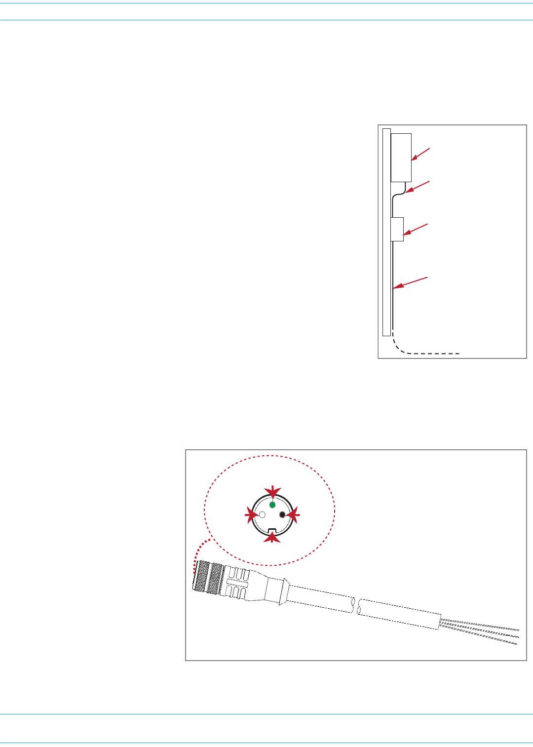
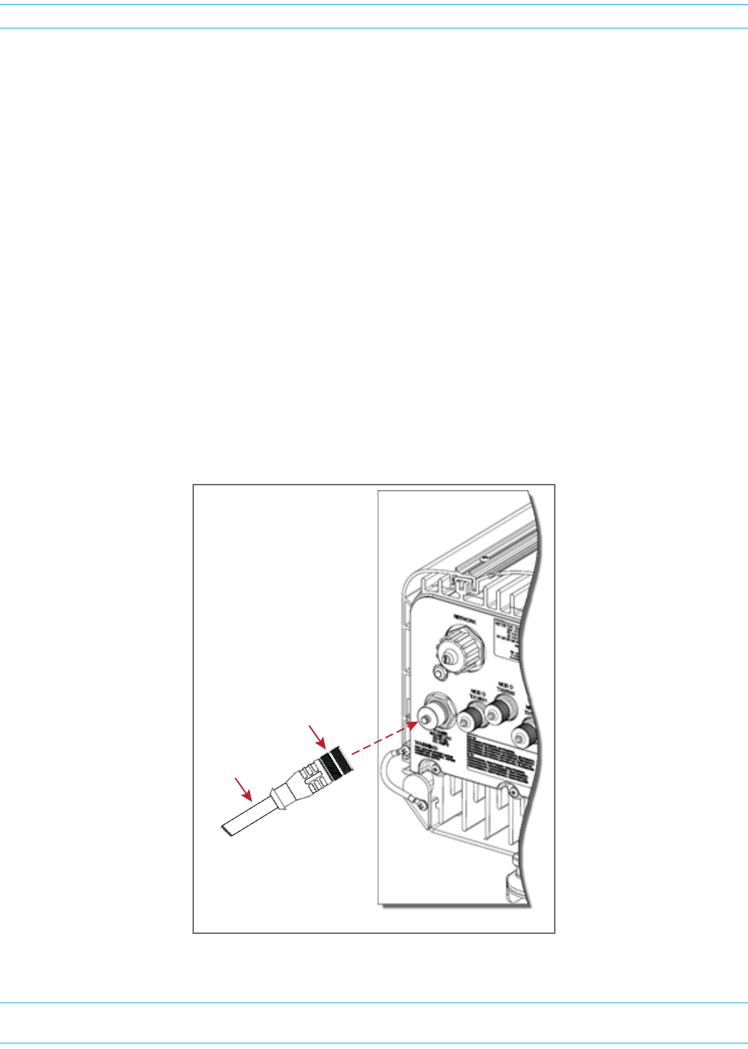
4AligntheplugendoftheBX5cableconnectorwiththeBX5portreceptacleandtheninsertthecable
plugintotheportreceptacleasshownbelow,andthenslidethestrainreliefbootoverthe
connector.
Fiber 1 is a
ProAx connector
that comprises
4 BX5 connectors
Shaded area is the
Alignment Key for
the BX5 cable
connector
BX5 Cable connector
FlexWave Prism Remote Unit and HDM RF Module Installation Guide 320000117795 Rev A • FWPP-501-01 Issue 1
Page 68 © March 2016 CommScope, Inc.
Install the Prism Remote Unit
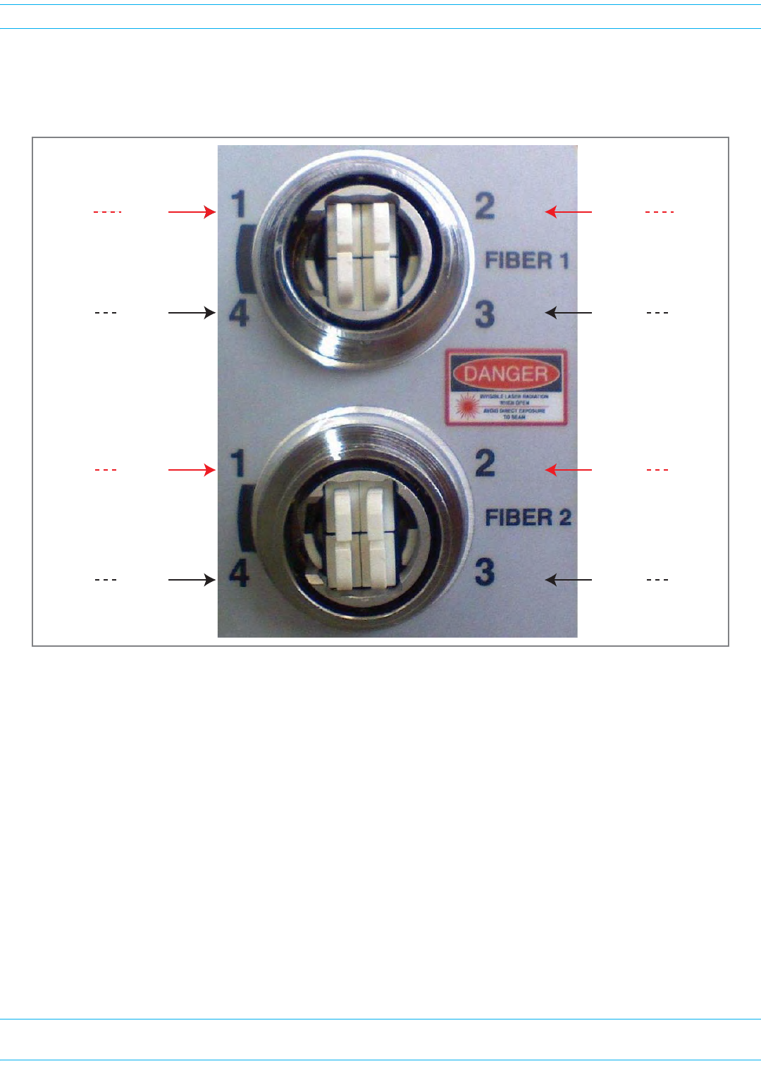
5RoutethefibercablefromtheundersideofthePRUtotheOSPbox.Observethefibernumbersand
theirpositionsinthequadcableconnectorasshownbelow.Thefibersattheotherendofthefiber
cablearenumberedwiththesamenumberingscheme.
6Securefibercableinplacefollowinglocalpractices.
7OneSFPequals12timeslotswith75MHzofbandwidth.Ifasecondfibercableassemblyisrequired
(forexample,yourPrismsystemhasthreeSFPstohandleupto280MHzofRFbandwidth),
completeStep1throughStep6toaddthesecondfibercableassembly,onlythistime,connecttothe
Fiber2ProAxconnectorlocatedatthebottomofthePRUasshowninStep1.
8Returntothemaininstallationprocessandcontinueat"ConnecttheAntennaCable”onpage69.
REV
Fiber 4
SFP2SFP2
SFP3SFP3 FWD
Fiber 1
SFP1SFP1 FWD
Fiber 1 SFP1SFP1
REV
Fiber 2
SFP3SFP3
REV
Fiber 2
SFP2SFP2
FWD
Fiber 3
SFP4SFP4
FWD
Fiber 3
SFP4SFP4 REV
Fiber 4
FWPP-501-01 Issue 1 • 320000117795 Rev A FlexWave Prism Remote Unit and HDM RF Module Installation Guide
© March 2016 CommScope, Inc. Page 69
Install the Prism Remote Unit
CONNECT THE ANTENNA CABLE
CoaxialantennacablesmustberoutedfromtheantennatothePRU.Thecablesmustbeterminated
withanN-TypemaleconnectorforconnectiontothePRUantennaportorthelightningsurge
suppressor(accessory).
CAUTION! The antenna(s) used for this transmitter must be fixed-mounted on (outdoor/indoor)
permanent structures. RF exposure compliance is addressed at the time of licensing, as
required by the responsible FCC Bureau(s), including antenna co-location requirements of 47
CFR. 1.307(b)(3).
Usethefollowingproceduretoinstalltheantennacable(s).Thisprocedurerequiresthatyouconnect
cabletooneAntennaconnectoratatime.
1Referto"UnderstandingRFCableRules”onpage26tounderstandtherelationshipbetweenantenna
numbersandRemoteRFmodules;thisinformationmakessureyouconnecttheAntennaconnectors
correctly.
2RemovethedustcapfromanN-typefemaleAntennaconnectorlocatedontheundersideoftheunit,
asshownbelow.IfyouneedtoinstallcablestomorethanoneAntennaconnector,startintherear
andworkforward,applyingthecorrecttorqueasyoumakeeachconnection.Workingfromtherear
portoutprovidesyouwiththespaceyouneedtoapplythecorrecttorque.
N-type female
Antenna port
for Module A
Antenna
cable
Lightning
Surge Suppressor
(ships with RF Module)
Surge port
connector
BoƩom View of PRU

FlexWave Prism Remote Unit and HDM RF Module Installation Guide 320000117795 Rev A • FWPP-501-01 Issue 1
Page 70 © March 2016 CommScope, Inc.
Install the Prism Remote Unit
3Connectalightningsurgesuppressortotheantennaport;torqueto8±1in-lbstoensurefull
connection.
NOTE: Lightening surge suppressor(s) ship with every RF Module. If the RF modules are populated in
the PRU from the factory, the lightening surge suppressors are in the Prism shipping crate. If
the RF Module is shipped individually, the lightening surge suppressor is shipped within the
RF Module shipping container.
4IfthePRUhasaaDual20WSMR800/PCS1900RFModule(FWP-441T841MOD),youmustinstall
aFlexWaveNotchFilter(FWP-SPRINTFILTER)betweenthePRUandtheantennatoprovide
protectionfromspuriousemissionsinthePublicSafetybandbelow861.35MHzandtheCellular
bandabove869.5MHz.ForinformationonhowtoinstallaNotchFilter,goto"FlexWaveNotchFilter
(FWP-SPRINTFILTER)”onpage108.
5Ensurethatthechassisgroundwireisinstalledcorrectly(see"GroundthePRUChassis”on
page52).Formaximumprotection,thesystemgroundwiremustbeattachedtoalowimpedance
groundsystem.
6RoutethecoaxialantennacablefromtheantennatotheundersideofthePRU.
7CuttheantennacabletotherequiredlengthandterminatewithanN-typemaleconnector.
8Connecttheantennacabletothelightningsurgesuppressorortotheantennaport;apply15in-lbs
(1.7Nm)oftorque.
CAUTION! The antenna cable connections must be weather proofed (sealed) for outdoor installations.
9RepeattheStep2throughStep8fortheremainingantennacables.
CONNECT THE POWER WIRING
ThePRUsupportsbothACandDCpower.Followthestepsappropriatetoyoursystemconfiguration:
•"Option1:ConnecttheACPowerWiring”onpage70
•"Option2:ConnecttheDCPowerWiring”onpage73.
Option 1: Connect the AC Power Wiring
A15-foot,3-wirecablewithconnectorsisprovidedfortheACpowerconnections.Theconnectorend
ofthecableconnectstotheACpowerportlocatedonthebottomoftheunit.Thestubendofthecable
mustberoutedtoanexternaljunctionbox(notprovided)forpermanentconnectiontotheACpower
systemwiring.IfthecablemustbeterminatedwithaplugtoconnecttotheACadapter,theplugmust
beprovidedbytheinstaller.
TheACpowersourcemustsupplybetween100and240Vac,50or60Hz,single-phasepowerthrough
acircuitbreakerorfuse.TheACpowercableprovidesthreewireleadsforline,neutral,andground
connections.Thepowercableisratedforindoororoutdooruseandmustnotbeplacedwithinelectrical
conduitasthiswillimpedethecoolingofthecableduringusage.Theelectricaljunctionboxandany
conduit,wire,andfittingsrequiredmustbeprovidedbytheinstaller.
CAUTION! Use extreme caution when working with high voltage AC power. Ensure all power is
disconnected before working on power circuits.
FWPP-501-01 Issue 1 • 320000117795 Rev A FlexWave Prism Remote Unit and HDM RF Module Installation Guide
© March 2016 CommScope, Inc. Page 71
Install the Prism Remote Unit
NOTE: All electrical work must comply with local codes and requirements. A locally licensed
electrical contractor is best qualified to perform this work. For additional information, consult
with the CommScope Technical Support for Wireless Products team (see "DCCSGlobal
TechnicalSupport”onpage119).
UsethefollowingproceduretoinstalltheACpowerwiring:
1LocatetheACpowercablethatisprovidedseparatelywiththe
PRU.
2RoutethepowercablebetweentheACpowerport,locatedonthe
undersideofthePRUandthenearestACpowerjunctionboxas
showninthegraphictotheright.Itmaybenecessarytoinstalla
newjunctionboxifanexistingjunctionboxisnotavailable.
3SecurethecablebetweentheACpowerportandtheACpower
junctionboxperlocalpractice.Leavesufficientslackinthecable
toallowittobeeasilyconnectedanddisconnectedfromtheAC
powerport.
NOTE: The power cable is rated for indoor or outdoor use and
must not be placed within electrical conduit as this will
impede the cooling of the cable during usage. The cable run
distance to the AC power source must not exceed 100 feet.
4InstallanyACpowersupplywiresthatmayberequiredbetween
theACjunctionboxandtheACcircuitbreakerbox.
NOTE: It is recommended that an AC outlet be installed near the PRU for powering tools and test
equipment. This outlet must include a GFCI device for protection.
NOTE: An appropriate disconnect device, as well as branch circuit protection, must be provided as
part of the installation.
5ConnecttheACpower
cablewirestotheAC
powersupplywires.Refer
tothegraphictotheright
toidentifythecolorcode
andwiredesignations;use
thealignmentkeyto
ensurethatthecable
correctlyalignswiththe
connector.Ifthecableis
notalignedcorrectlywith
theconnector,connector
pinsmaybedamaged.
Remote enclosure
AC power juncƟon box
AC power cable
AC power wires routed
to circuit breaker panel
M16 Connector
3 Black1 White
Female-End View
2 Green
Alignment key
FlexWave Prism Remote Unit and HDM RF Module Installation Guide 320000117795 Rev A • FWPP-501-01 Issue 1
Page 72 © March 2016 CommScope, Inc.
Install the Prism Remote Unit
6AttheACbox,connecttheACpowersupplyloadwirestoacircuitbreakerorfuse.
CAUTION! For proper and safe equipment operation, an approved earth ground connection must be
provided and maintained.
7Connectthegroundwiretoanapprovedearthground.
8PlacethecircuitbreakerintheONpositionandthentesttheconnectorendoftheACpowercable
forpropervoltagelevelsandcorrectpolarity.
9Whentestingiscomplete,placethecircuitbreakerintheOFFposition.
10 RemovethedustcapfromtheACpowerportlocatedonthebottomofthePRUasshownbelow.
CAUTION! While trying to connect the AC power cable to the PRU AC power port, it is possible for the
line terminal on the cable connector to contact the ground pin on the power port. If the AC
cable is energized, this will result in a direct short to ground for the AC power. To avoid
possible personal injury and equipment damage, always turn the AC power off before
connecting the AC power cable to the AC power port.
11 ConnectthepowercableconnectortotheACpowerport;usethealignmentkeytoensurethatthe
cablecorrectlyalignswiththeconnector.Ifthecableisnotalignedcorrectlywiththeconnector,
connectorpinsmaybedamaged.
12 Tightenthecouplingnutonthepowerconnector.
BoƩom of PRU
Coupling nut
Power cable
FWPP-501-01 Issue 1 • 320000117795 Rev A FlexWave Prism Remote Unit and HDM RF Module Installation Guide
© March 2016 CommScope, Inc. Page 73
Install the Prism Remote Unit
Option 2: Connect the DC Power Wiring
NOTE: All electrical work must comply with local codes and requirements. A locally licensed
electrical contractor is best qualified to perform this work. For additional information, consult
with the CommScope Technical Support for Wireless Products team (see "DCCSGlobal
TechnicalSupport”onpage119).
1ObtainaDCpowercablethatmeetsthefollowingrequirements:
•TheDCpowercablecanbe8AWGor6AWG,3-or4-conductorpowercableratedforoutdoor
use.
•Thewirecolorsmustbegreen,red,andblack.
•Thecablemustbebetween.71-inchto.98-inchindiameter.
•Ifa4-conductorpowercableisused,theextraconductorcanbesnippedoffbeforeinstallation.
•Ifusing6AWGwire,theinstallermustprovideanduse#10studsize,6AWGringterminals.
2Removethecable-glandplugfromthebottomofthePRUchassis:
Cable-gland plug
FlexWave Prism Remote Unit and HDM RF Module Installation Guide 320000117795 Rev A • FWPP-501-01 Issue 1
Page 74 © March 2016 CommScope, Inc.
Install the Prism Remote Unit
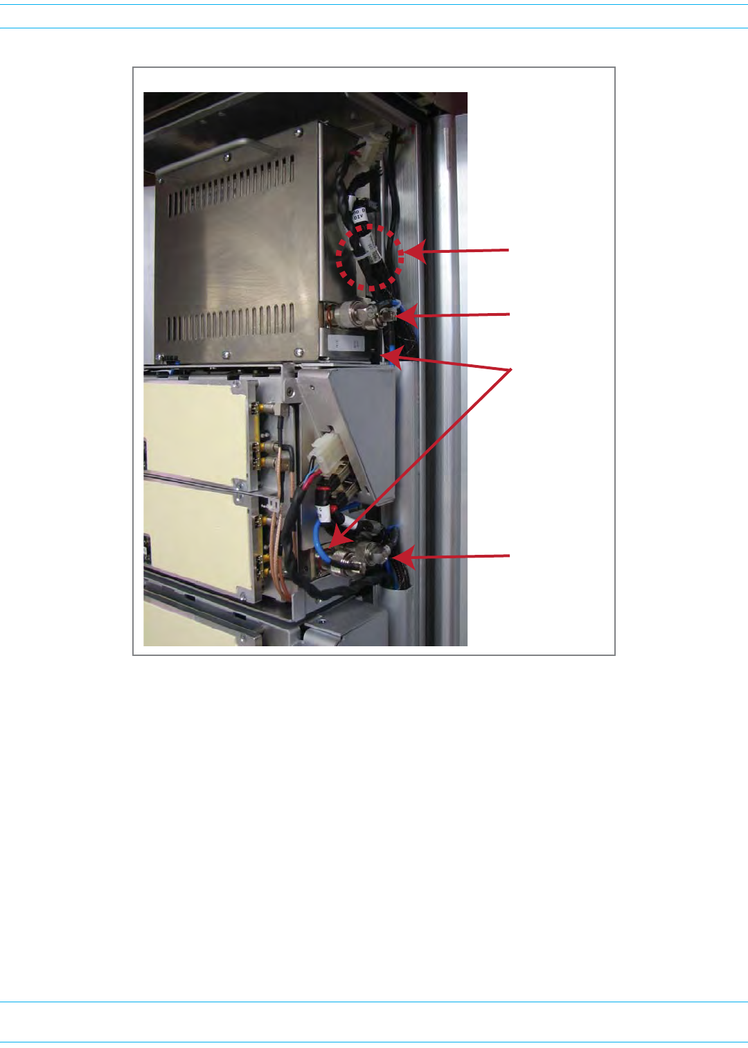
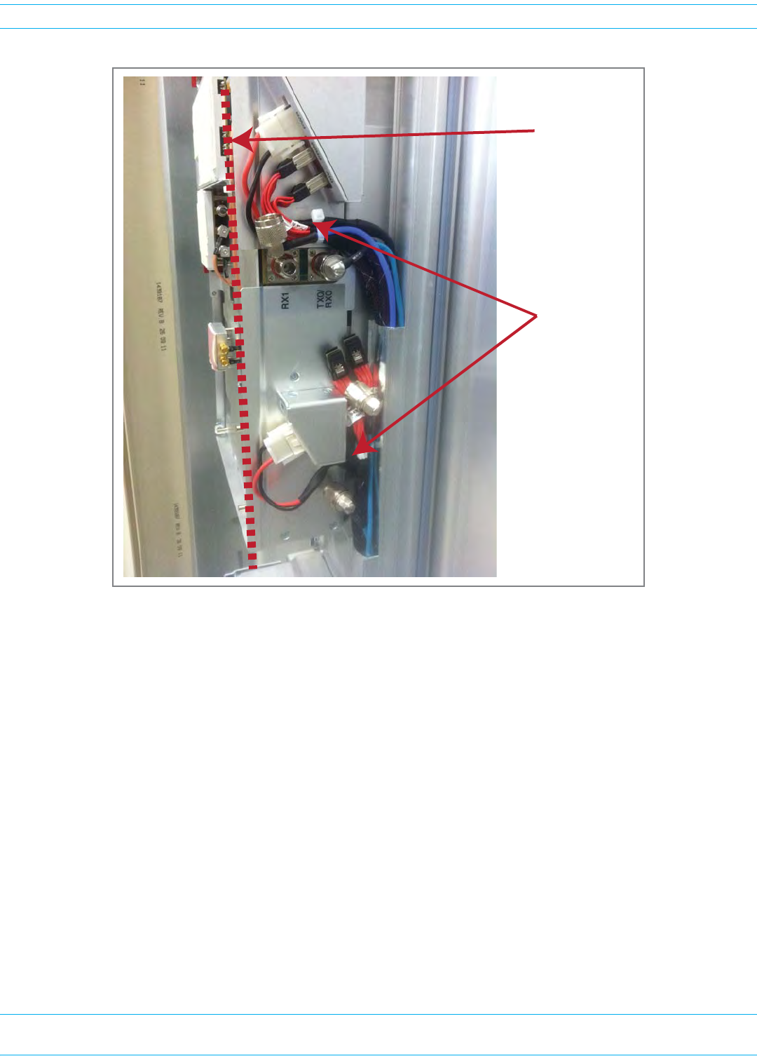
3Disconnecttheringterminalsfromthepower-terminalblock:
4ConnecttheDCpowercabletothePRU.
PosiƟve (+)
NegaƟve (-)
Earth ground
PosiƟve (+)
NegaƟve (-)
Earth ground
Step 4a
Steps 4b and 4c
Step 4d

FWPP-501-01 Issue 1 • 320000117795 Rev A FlexWave Prism Remote Unit and HDM RF Module Installation Guide
© March 2016 CommScope, Inc. Page 75
Install the Prism Remote Unit
aRoutetheendoftheDCpowercablewiththethreeconductorsthroughtheopencable-gland
connectoronthebottomofthePRU.
bCrimpthethreeconductorstothepowerringterminals.Theterminalblockislabeledasto
whereeachwireshouldbeconnected,asdescribedbelow.
•Inatypical-48Vdcplant,thehighestpotentialisthe0(groundorreturn)lead;you
therefore:
–connectthe0(groundorreturn)leadtothepositive(+)connector(redwire)
–connectthe-48Vdcleadtothenegative(-)connector(blackwire)
–connectthethirdwire,ifprovided,totheEarthGroundterminal.
•Ina+48Vdcplant,thehighestpotentialisthe+48lead;youtherefore:
–connectthe+48leadtothepositive(+)connector(redwire)
–connectthe0potential(groundorreturn)tothenegative(-)connector(blackwire)
–connectthethirdwire,ifprovided,totheEarthGroundterminal.
cUseaPhillipsscrewdrivertotorquetheringterminalsto18in-lbs.
dUsea42MMwrenchtotorquethelargenutoutsidethecableglandto44in-lbs.
5ConnectthewirestothedesignatedterminalsontheDCPowerSourceDistributionPanel.The
followingconnectionsaretypicallymade:
•Inatypical-48Vdcplant,thehighestpotentialisthe0(groundorreturn)lead;youtherefore:
–connectthe0(groundorreturn)leadtothepositive(+)connector(redwire)
–connectthe-48Vdcleadtothenegative(-)connector(blackwire)
–connectthethirdwire,ifprovided,totheEarthGroundterminal.
•Ina+48Vdcplant,thehighestpotentialisthe+48lead;youtherefore:
–connectthe+48leadtothepositive(+)connector(redwire)
–connectthe0potential(groundorreturn)tothenegative(-)connector(blackwire)
–connectthethirdwire,ifprovided,totheEarthGroundterminal.
6Dressandsecurethewirestotherackfollowinglocalpractice.Routewiringawayfromsharpedges
andsecureinplacetopreventchaffingandprovidestrainrelief.
NOTE: Route all DC input wiring away from any sharp edges and properly secure it in place to prevent
chafing and to provide strain relief. Lace the wires to the rack frame.

FlexWave Prism Remote Unit and HDM RF Module Installation Guide 320000117795 Rev A • FWPP-501-01 Issue 1
Page 76 © March 2016 CommScope, Inc.
Install the Prism Remote Unit
DETERMINE THE CIRCUIT BREAKER OR FUSE FOR THE PRU
AnAC-poweredPRUsupportspowerinputfroma90to240Vacpowersupply.ADC-poweredPRU
supportspowerinputfroma-40to-60Vdcpowersupply.
Power Consumption
1Calculatethemaximumpowerconsumption,whichdeterminesthecircuitbreakerorfusetouse.
aReviewthePRUordertodeterminethenumberofDARTs,numberofpowersupplies,andthe
numberofSFPs.UsethisinformationtofindthepowerconsumptionfromTable22onpage76
andTable23onpage77.
bEnterthepowerconsumptioninthespacesprovidedbelow.
cAddtheWattsandenterthetotalintheTotalPowerConsumptionfield.
2DividethetotalWattsbytheinputVoltagetodeterminethecurrent(Amperes)requirements:
TotalWatts/InputVoltage=Amps
3Determinethecircuitbreakerorfusesizebasedonlocalcodesandpractices.
CAUTION! Circuit breaker or fuse size must be 20 Amps or less to protect the internal wiring of the PRU.
Power Consumption Tables
ThePRUpowersuppliesare>80%efficient,bothACandDCversions.ThedatainTable22andTable23
onpage77andthepower-supplyefficienciescanbeusedtoestimatetheinputcurrentforagivenPRU
configuration.Tocalculatetheinputcurrentdrawusethefollowingequation:
Input Current = (Total Power Consumption / 0.80) / Input Voltage
Forexample,foraPRUwith1SeRFModule,1SFP(36WTypical,38WMax),andasingle20W850/1900
HDMRFModule(250WTypical,330WMax),thentheTotalPowerConsumptionwouldbe286W
(Typical)and368W(Max).Therefore,fora110VACinput,thecurrentestimatewouldbe3.25amps
(Typical)and4.18amps(Max).
SeRFModulepowerconsumptionfromTable22onpage76 _________Watts
AdditionalSFPs_____x1.25W _________Watts
RFModulepowerconsumptionfromTable23onpage77 _________Watts
TotalPowerConsumption _________Watts
Table 22. SeRF Module Power Consumption
SeRF Module
Power Consumption per Module
Nominal (W) @ 25C Maximum (W)
SeRF Module (1 SFP) [add 1.25W for each SFP added] 36 38

FWPP-501-01 Issue 1 • 320000117795 Rev A FlexWave Prism Remote Unit and HDM RF Module Installation Guide
© March 2016 CommScope, Inc. Page 77
Install the Prism Remote Unit
Table 23. Power Consumption by RF Module
Prism RF Module Description
Power Consumption Per Module
Nominal (W) @
25C
Maximum
(W)
Single or Dual
SuperDART RF
Module
20W 1900 PCS, 20W 2100AWS, 700 LTE Non-Diversity 299 368
40W 700 LTE Non-Diversity 299 368
40W 1900 PCS, 40W 2100 AWS (Dual AMPs) Non-Diversity 568 706
10W GSM900 (Includes EGSM, PGSM, APAC,
GSM)
Non-Diversity 299 337
Diversity 321 359
15.8W GSM1800
Non-Diversity 299 337
Diversity 321 359
15.8W 2100UMTS
Non-Diversity 299 337
Diversity 321 372
HDM RF Modules
40W 850 Cell SISO HDM SISO - Non-Diversity 249 315
40W 1900 PCS SISO HDM SISO - Non-Diversity 249 315
40W 2100 AWS SISO HDM SISO - Non-Diversity 249 315
20W 700 MIMO LTE HDM (LABC or uC) MIMO - Non-Diversity 250 330
20W 1900 PCS MIMO HDM MIMO - Non-Diversity 250 330
20W 2100 AWS MIMO HDM MIMO - Non-Diversity 250 330
20W 1900 PCS MIMO HDM MIMO - Non-Diversity 250 330
20W 800 SMR MIMO HDM MIMO - Non-Diversity 250 330
20W 850 Cell MIMO HDM MIMO - Non-Diversity 250 330
20W 850/1900 HDM Dual HDM -
Non-Diversity
250 330
20W 700 LABC/700 uC Dual HDM Dual HDM -
Non-Diversity
250 330
20W 800/1900 HDM Dual HDM -
Non-Diversity
250 330
20W 1900/2100 HDM Dual HDM -
Non-Diversity
250 330
20W 2500 TDD Low HDM MIMO - Non-Diversity 250 330
20W 2500 TDD High HDM SISO - Non-Diversity 175 230
Classic DART RF
Module
20W 1900 PCS or 2100 20W AWS
Non-Diversity 292 358
Diversity 314 381
6.5W 800/900 ESMR Non-Diversity 195 196
40W 850 Cell Non-Diversity 299 368
20W 850 CELL
Non-Diversity 271 327
Diversity 293 350
FlexWave Prism Remote Unit and HDM RF Module Installation Guide 320000117795 Rev A • FWPP-501-01 Issue 1
Page 78 © March 2016 CommScope, Inc.
Install the Prism Remote Unit
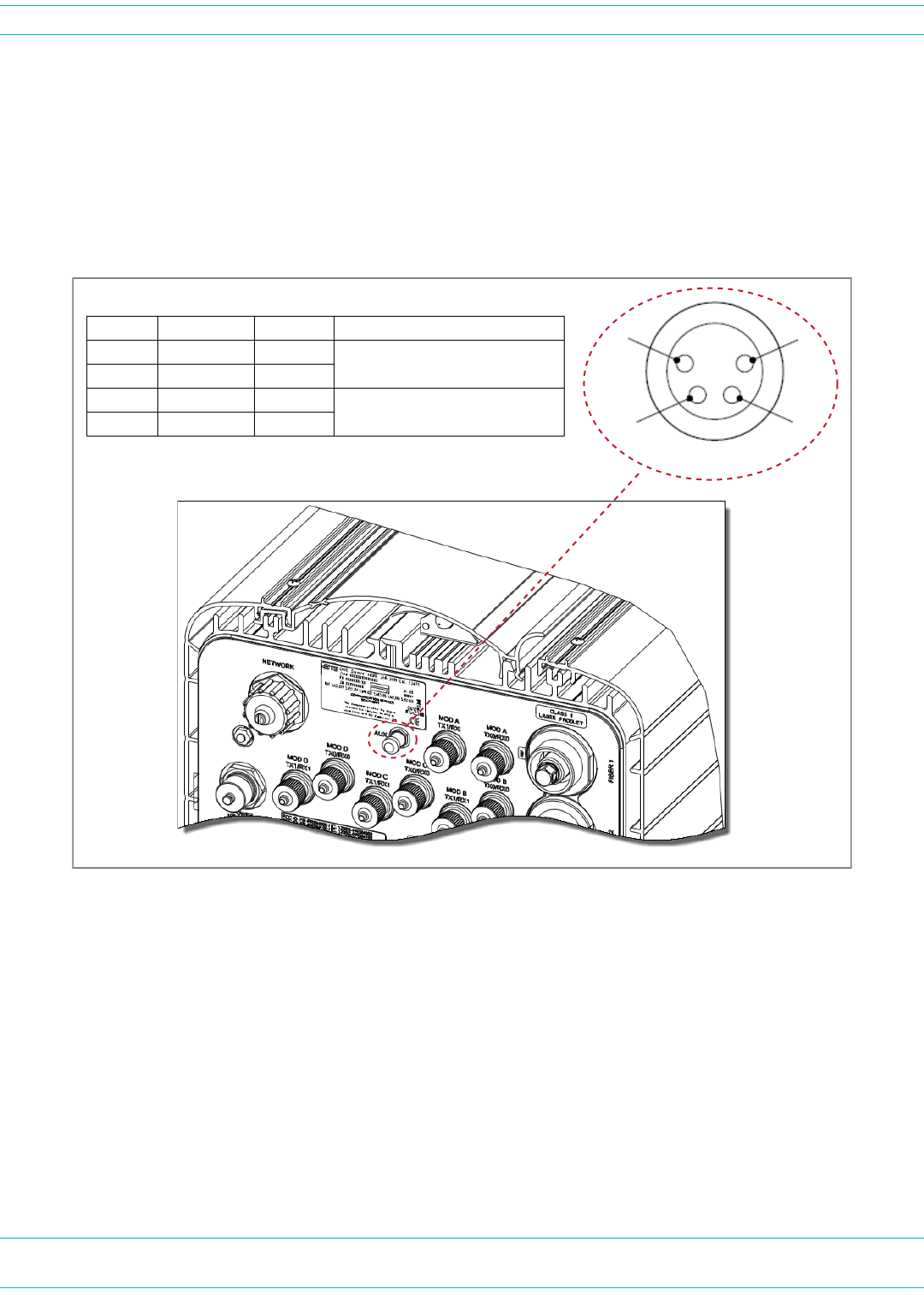
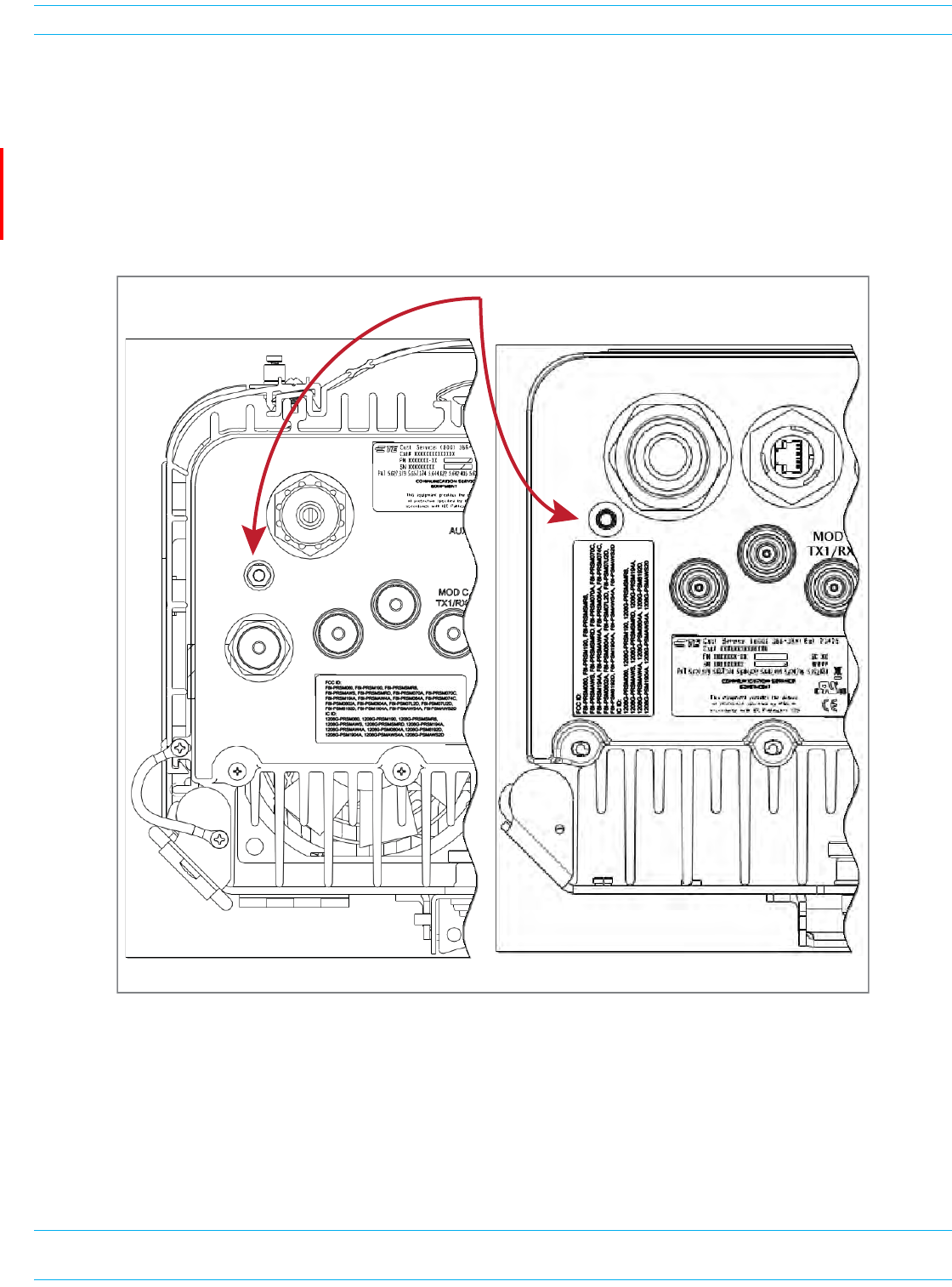
(OPTIONAL) CONNECT THE PRISM REMOTE UNIT TO A UPS
Thefour-pinAUXConnectoronthebottomofthePRUallowsthePRUtobeconnectedtoanexternal
devicewithdrycontactconnections,suchasaUninterruptedPowerSupply(UPS).TheAUXConnector
pinsareshowninFigure17.
NOTE: The Normally Open (NO) or Normally Closed (NC) options are configurable in the GUI; see the
“Manage Contact Alarms” section of the current EMS System Setup and Provisioning Guide.
Figure 17. AUX Connector Pin Orientation
NOTE: The Major/Minor setting of the AUX Connector pins cannot be configured in the Prism 6.x
EMS GUI. In Prism 7.x, you can configure the Contact Alarm as Major or Minor (Alarms >
Manage Contact Alarms).
1
2
4
3
AUX Connector
BoƩom of PRU
Pin # Contact Color Alarm Input
1 NO/NC Brown Major External Alarm Input
2 CO White
3 NO/NC Blue Minor External Alarm Input
4 CO Black
FWPP-501-01 Issue 1 • 320000117795 Rev A FlexWave Prism Remote Unit and HDM RF Module Installation Guide
© March 2016 CommScope, Inc. Page 79
Install the Prism Remote Unit
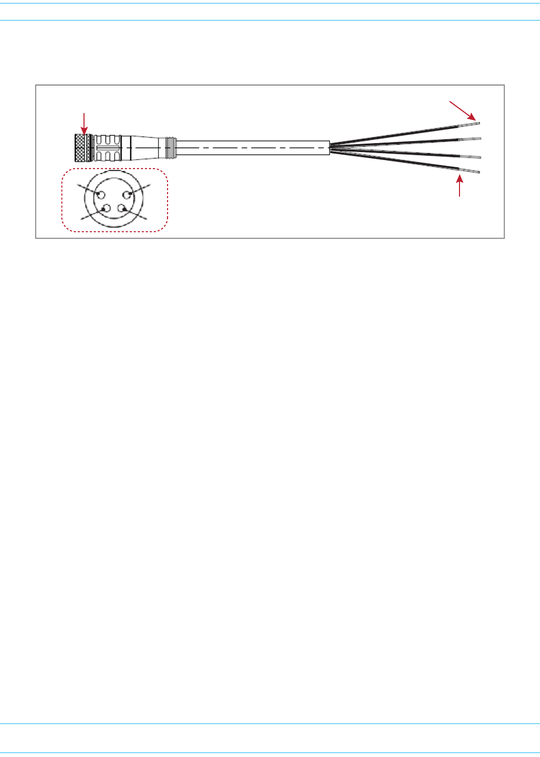
A4-WireM8picofast®6-or10-meter26AWGcableisusedtoconnectthePRUtotheexternaldevice,
asshowninFigure18.
Figure 18. 4-Wire picofast 26 AWG Cable
DothefollowingtoconnectaUPStotheAUXConnectoronthebottomofthePRU:
1Obtaintherequiredlengthof6-or10-meterpicofastcable.
2Orientthecouplingfasteneronthecable(Figure18)withtheAUXConnectorpins(Figure17),and
thenfastenthecabletotheAUXConnector.
3RoutethecablefromthePRUAUXConnectortotheUPS(ifnotalreadyrouted)andthencuttothe
requiredlength.Allowsufficientslackfordressingandorganizingthecableattheexternaldevice.
4Stripbacktheoutercablesheathandinsulationtoexposethewiresattheendofthecableandstrip
back0.2inches(5mm)ofinsulationfromeachwire.
5Connectthealarmwirepairstotheappropriateterminalsontheexternaldevice.
6Dressandsecurecableperstandardindustrypractice.
NOTE: If necessary, order a Prism AUX 4-wire cable assembly, CommScope part number 1451903.
Strip cable
0.2 inches (5 mm)
Connect 4 wires to UPS
Connect to
PRU AUX Connector
24
13

FlexWave Prism Remote Unit and HDM RF Module Installation Guide 320000117795 Rev A • FWPP-501-01 Issue 1
Page 80 © March 2016 CommScope, Inc.
Install the RF Module(s)
INSTALL THE RF MODULE(S)
ThefollowingsectionsguideyouthroughtheinstallationofanRFModuleintoaRemoteUnitchassis.
TheprocesstoinstallthefourdifferenttypesofRFModulesisbasicallythesame;however,differences
arenotedandshouldbefollowed.
NOTE: In the following steps, the RF cables and connectors are referred to as MOD N TX0/RX0 and
as MOD N TX1/RX1 where N equals A, B, C, or D.
NOTE: When installing RF Modules, populate the RF Modules from highest frequency band to lowest
within the Remote Unit chassis. Likewise for power output, populate from the bottom bay to
the top; higher output to lower output. That is, for a deployment with 2100 40W, 1900 40W,
850 20W and 700 20W MIMO, install the RF Modules as follows:
• 2100 40W RF Module in Bay A
• 1900 40W RF Module in Bay B
• 850 20W RF Module in Bay C
• 700 20W MIMO RF Module in Bay D.
SAFETY PRECAUTIONS
CAUTION! This is restricted access equipment and only qualified service personnel should service and
operate this equipment using appropriate tools.
CAUTION! Wet conditions increase the potential for receiving an electrical shock when installing or using
electrically-powered equipment. To prevent electrical shock, never install or use electrical
equipment in a wet location or during a lightning storm.
CAUTION! Always allow sufficient fiber length to permit routing of patch cords and pigtails without
severe bends. Fiber optic patch cords or pigtails may be permanently damaged if bent or
curved to a radius of less than 2 inches (5.1 cm).
CAUTION! Exterior surfaces of the Prism Remote Unit may be hot. Use caution during servicing.
CAUTION! Service personnel must confirm that the perimeter gasket and door-to-door gaskets are in
place when closing the Remote Unit doors after servicing.
CAUTION! This equipment uses a Class 1 Laser according to FDA/CDRH rules. Laser radiation can
seriously damage the retina of the eye. Do not look into the ends of any optical fiber. Do not
look directly into the optical transceiver of any digital unit or exposure to laser radiation may
result. An optical power meter should be used to verify active fibers. A protective cap or hood
MUST be immediately placed over any radiating transceiver or optical fiber connector to
avoid the potential of dangerous amounts of radiation exposure. This practice also prevents
dirt particles from entering the adapter or connector.
CAUTION! This system is an RF Transmitter and continuously emits RF energy. Maintain 3 foot (91.4 cm)
minimum clearance from the antenna while the system is operating. Wherever possible, shut
down the RAN before servicing the antenna.

FWPP-501-01 Issue 1 • 320000117795 Rev A FlexWave Prism Remote Unit and HDM RF Module Installation Guide
© March 2016 CommScope, Inc. Page 81
Install the RF Module(s)
GUARD AGAINST DAMAGE FROM ELECTRO-STATIC DISCHARGE
CAUTION! Electro-Static Discharge (ESD) can damage electronic components. To prevent ESD damage,
always wear an ESD wrist strap when working with a Prism Remote Unit or when handling any
of its components—including the RF Modules. Connect the ground wire on the ESD wrist strap
to an earth ground source before touching the Prism Remote Unit or any of its components.
Wear the wrist strap the entire time that you work with the Prism Remote Unit and its
components.
CAUTION! Place Prism RF Modules in anti-static packing material when transporting or storing them.
UNPACK AND INSPECT THE RF MODULE
1Inspecttheexterioroftheshippingcontainer(s)forevidenceofroughhandlingthatmayhave
damagedthecomponentsinthecontainer.
2Unpackeachcontainerwhilecarefullycheckingthecontentsfordamageandverifywiththepacking
slip.
3Ifdamageisfoundorpartsaremissing,fileaclaimwiththecommercialcarrierandnotify
CommScopeCustomerService(see"DCCSGlobalTechnicalSupport”onpage119).Savethe
damagedcartonsforinspectionbythecarrier.
4Saveallshippingcontainersforuseiftheequipmentrequiresshipmentatafuturedate.
CAUTION! Handle the RF Module with care during installation. Be especially careful to not damage the
thermal-interface material (TIM), which is attached to the LPA, DARTs, and/or Motherboard
with TX/RX boards. If the TIM is damaged, the LPA can overheat. Before installing the RF
Module, check to see if the heatsink material is gouged or cracked. If the TIM is damaged, do
not install the RF Module and contact CommScope for assistance (see "DCCSGlobalTechnical
Support”onpage119 for contact information).
CAUTION! If the thermal-interface material is damaged, the installation and use of the RF Module may
void the warranty of the RF Module.
FlexWave Prism Remote Unit and HDM RF Module Installation Guide 320000117795 Rev A • FWPP-501-01 Issue 1
Page 82 © March 2016 CommScope, Inc.
Install the RF Module(s)
REMOVE RELEASE LINERS FROM THE RF MODULE
NOTE: Release Liners are present on front and back of new modules.
1OpentheRemoteUnitenclosure.
2Removereleaseliners,ifpresent,fromthethermalpadsontheRFModulepriortoinstallingthe
moduleintotheRemoteUnitchassis.
CAUTION! The thermal pads are very sensitive to mishandling—do not nick, scratch, or ding them.
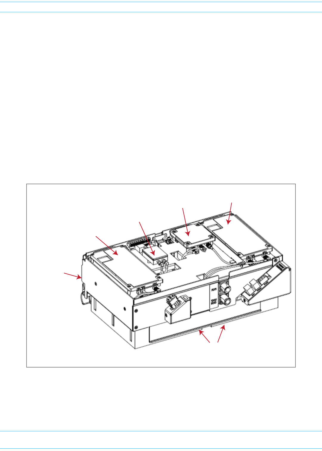
ForSingle-andDual-BayRFModules,thethermalpadsarelocatedaslistedbelowandasshownin
Figure19,whichshowsaLegacyDual-Bay40WRFModule.
•onelargepadonthebacksurfaceofeachLinearPowerAmplifier(LPA)
•uptotwoonthefrontsurface(DARTs)
•oneontheleftsideforthe(RDI)
•oneonthevectormodulatorboard
•oneontheRFpowercombiner.
Figure 19. Thermal Pads on a Legacy Dual-Bay 40W RF Module
One large
thermal pad on each PA
(boƩom of the LPA)
One thermal pad
for the RDI
One thermal pad
for each DART
One thermal pad
for each DART
One thermal pad
for RF Power
Combiner
One thermal pad
for Vector
Modulator
FWPP-501-01 Issue 1 • 320000117795 Rev A FlexWave Prism Remote Unit and HDM RF Module Installation Guide
© March 2016 CommScope, Inc. Page 83
Install the RF Module(s)
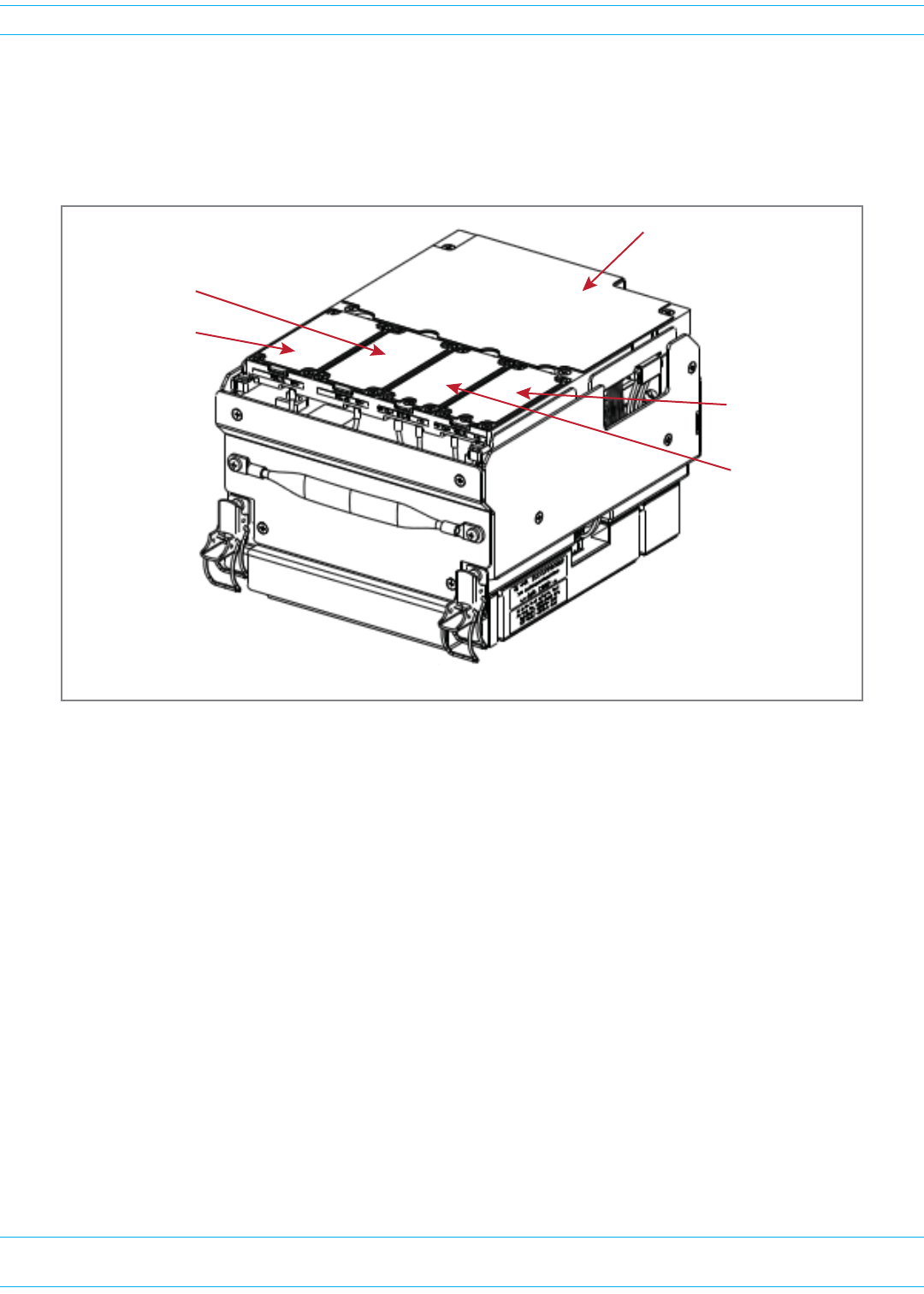
ForHDMRFModules,thethermalpadsarelocatedaslistedbelowandasshowninFigure20.
•onepadforeachRxandTxboard
•onelargepadovertheDPM
•oneforeachPowerAmplifier(PA),whichisonthebottomoftheHDMRFModule.
Figure 20. Thermal Pads on an HDM RF Module
DPM Thermal Pad
Tx A Thermal Pad
Tx B Thermal Pad
Rx A Thermal Pad
Rx B Thermal Pad
NOTE: Tx and Rx cards are paired: Tx A ony pairs with Rx A and Tx B only pairs with Rx B.
FlexWave Prism Remote Unit and HDM RF Module Installation Guide 320000117795 Rev A • FWPP-501-01 Issue 1
Page 84 © March 2016 CommScope, Inc.
Install the RF Module(s)
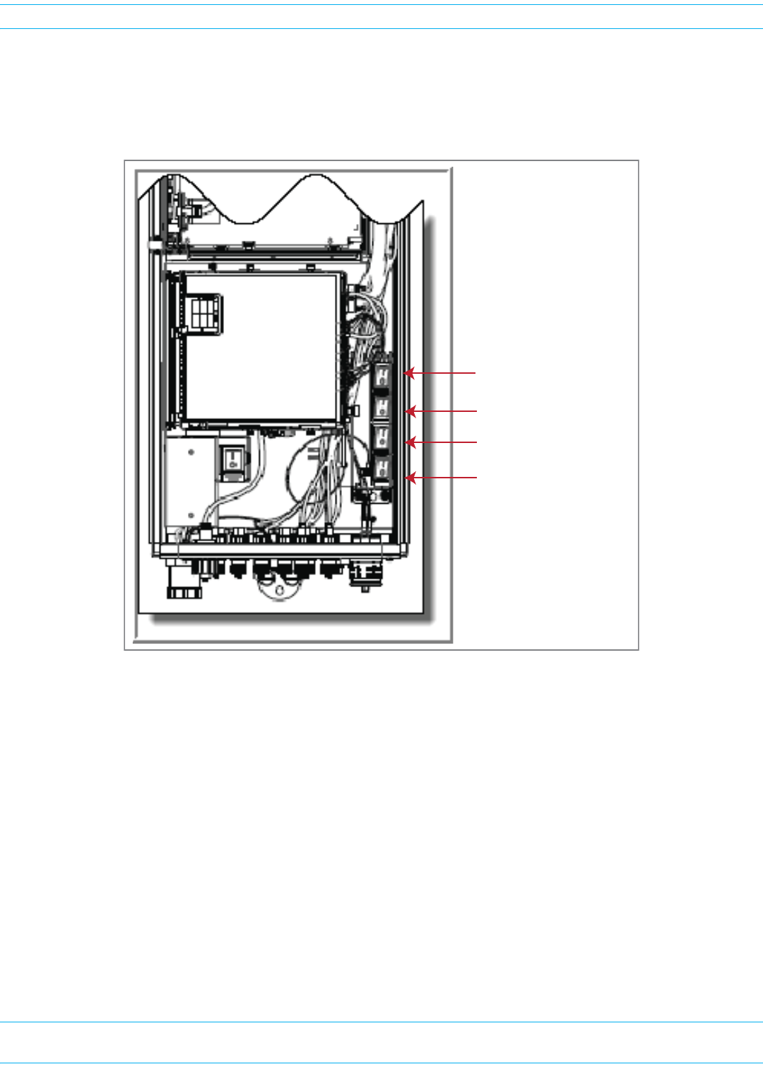
CHECK THE DC POWER SWITCH FOR THE MODULE BAY
EnsurethattheDCpowerswitchthatcorrespondstothebay(s)inwhichtheRFModuleistobe
installedisintheOffposition:
DC Power switch for Bay A
DC Power switch for Bay B
DC Power switch for Bay C
DC Power switch for Bay D
FWPP-501-01 Issue 1 • 320000117795 Rev A FlexWave Prism Remote Unit and HDM RF Module Installation Guide
© March 2016 CommScope, Inc. Page 85
Install the RF Module(s)
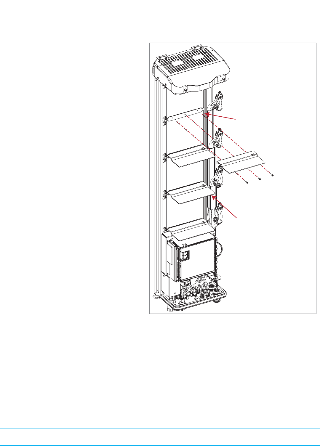
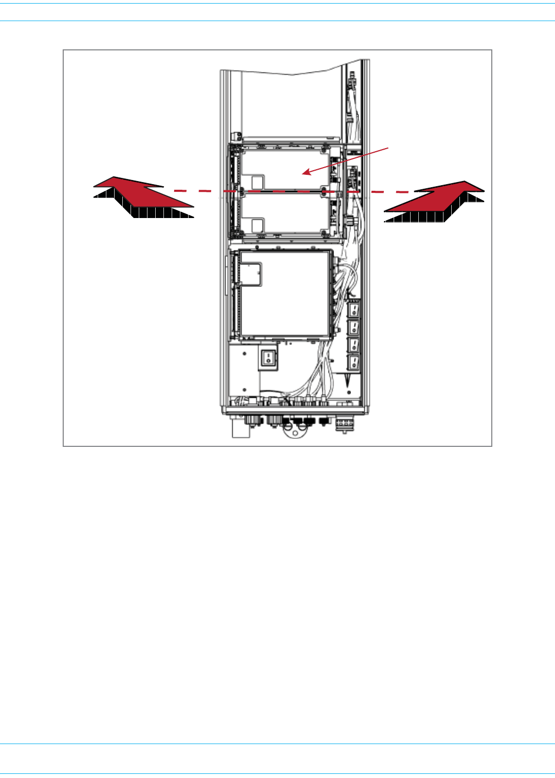
DUAL-BAY MODULES ONLY—REMOVE THE MODULE BAY SHELF
FORDUAL-BAYRFMODULESONLY.
IfyouareinstallingaDual-BayRFModule,
youmustremoveamodulebayshelffrom
thePRUchassistoaccommodatethe
module’ssize.(Forfurtherinformation,see
Table16onpage27.)
RemovetheshelfasappropriatefortheRF
Module:
•WheninstallingintheAandBBays,
removetheModuleBBayShelf.
•WheninstallingintheCandDBays,
removeModuleDBayShelf.
ToremoveaModuleBayShelf:
1Usea9/64”Allen™wrenchtoremove
thethreescrewsthatattachthemodule
shelftothePRUchassis,asshowninthe
graphictotheright.
2Discardorstorethemoduleshelfand
fasteners.
Use 9/64” Allen Wrench to
remove the three module-shelf screws
Remove Module D Shelf for
Dual-Band Dual-Slot RF Modules
Remove Module B Shelf for
Dual-Slot 40W RF Modules
FlexWave Prism Remote Unit and HDM RF Module Installation Guide 320000117795 Rev A • FWPP-501-01 Issue 1
Page 86 © March 2016 CommScope, Inc.
Install the RF Module(s)
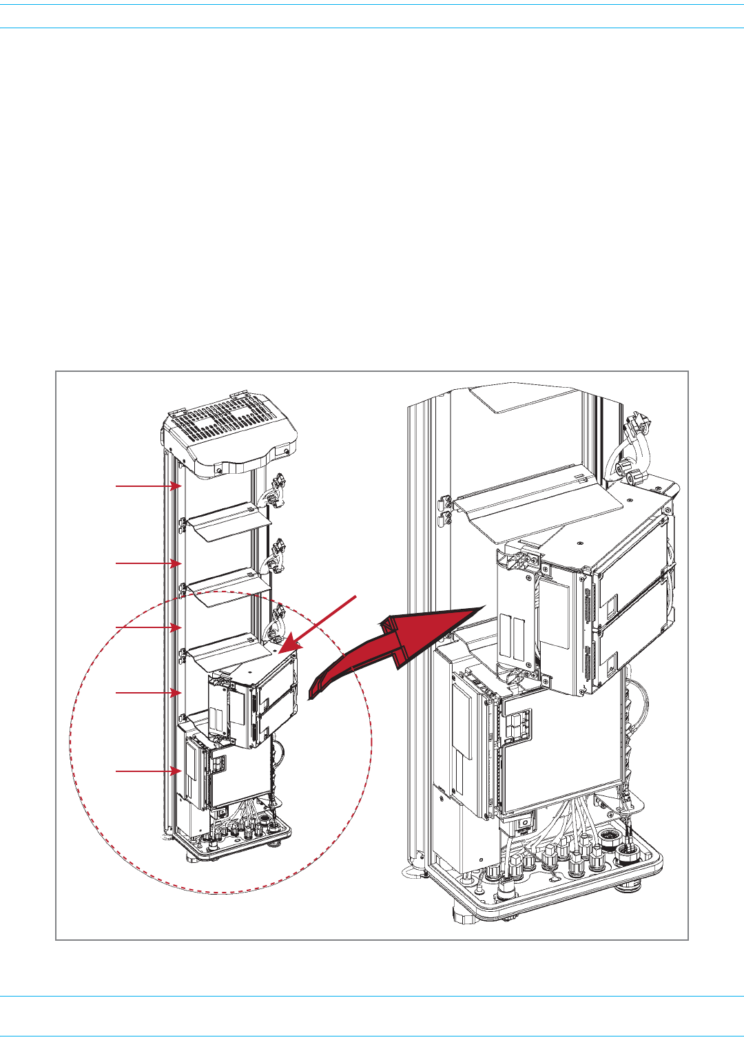
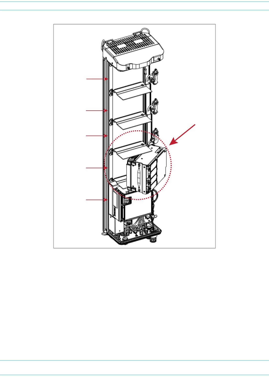
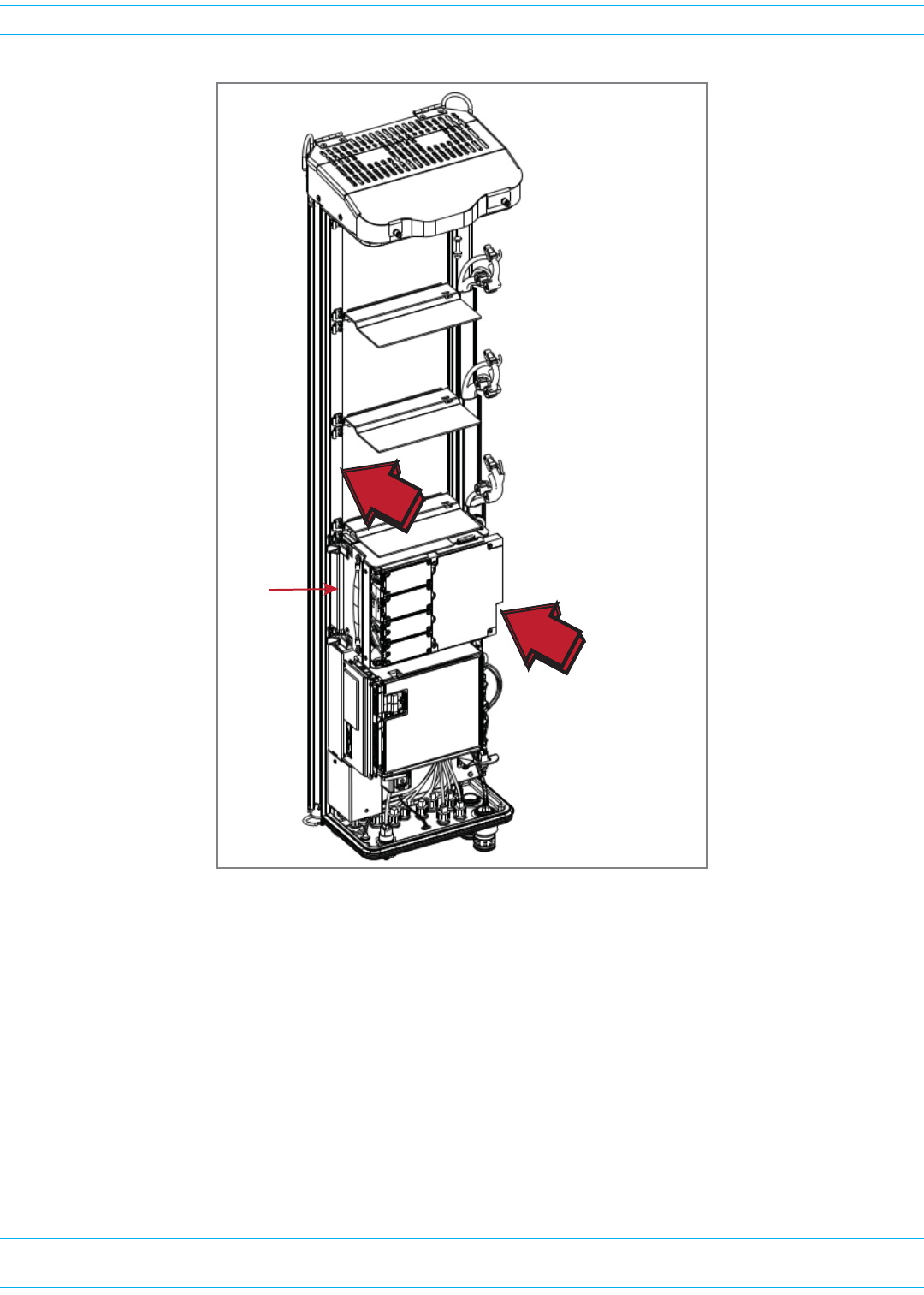
INSTALL THE RF MODULE INTO THE PRISM REMOTE CHASSIS
1HoldtheRFModulesothattheDARTcard(s)faceawayfromthePRUandtheMountingHookis
towardtheReceivingflangeonthePRUchassis.
NOTE: Always install RF Modules from the bottom up. Do not skip a bay, as this provides more
efficient heat dissipation.
2HoldingtheRFModuleata45°angleinrespecttotherearheatsink,restthebottomsurfaceofthe
moduleontheRFModuleshelf,asshowninoneofthefollowinggraphics,andasapplicabletothe
RFModule.
•Single-BayRFModule:Figure21onpage86
•HDMRFModule:Figure22onpage87
•Dual-BayRFModule:Figure23onpage88
•LegacyDual-Bay40WRFModule:Figure24onpage89.
Figure 21. Installing a Single-Bay RF Module
Bay C
Bay D
SeRF
Module
Bay A
Bay B
Single-Slot
RF Module
Heat Sink
FWPP-501-01 Issue 1 • 320000117795 Rev A FlexWave Prism Remote Unit and HDM RF Module Installation Guide
© March 2016 CommScope, Inc. Page 87
Install the RF Module(s)
Figure 22. Installing an HDM RF Module
Bay C
Bay D
SeRF Module
Bay A
Bay B
HDM RF Module
FlexWave Prism Remote Unit and HDM RF Module Installation Guide 320000117795 Rev A • FWPP-501-01 Issue 1
Page 88 © March 2016 CommScope, Inc.
Install the RF Module(s)
Figure 23. Installing a Dual-Bay RF Module
Installing a Dual-Band
Dual-Slot RF Module
FWPP-501-01 Issue 1 • 320000117795 Rev A FlexWave Prism Remote Unit and HDM RF Module Installation Guide
© March 2016 CommScope, Inc. Page 89
Install the RF Module(s)
Figure 24. Installing a Legacy Dual-Bay 40W RF Module
FlexWave Prism Remote Unit and HDM RF Module Installation Guide 320000117795 Rev A • FWPP-501-01 Issue 1
Page 90 © March 2016 CommScope, Inc.
Install the RF Module(s)
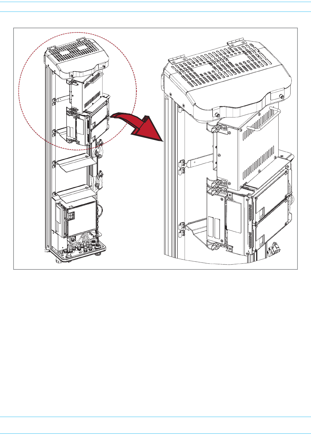
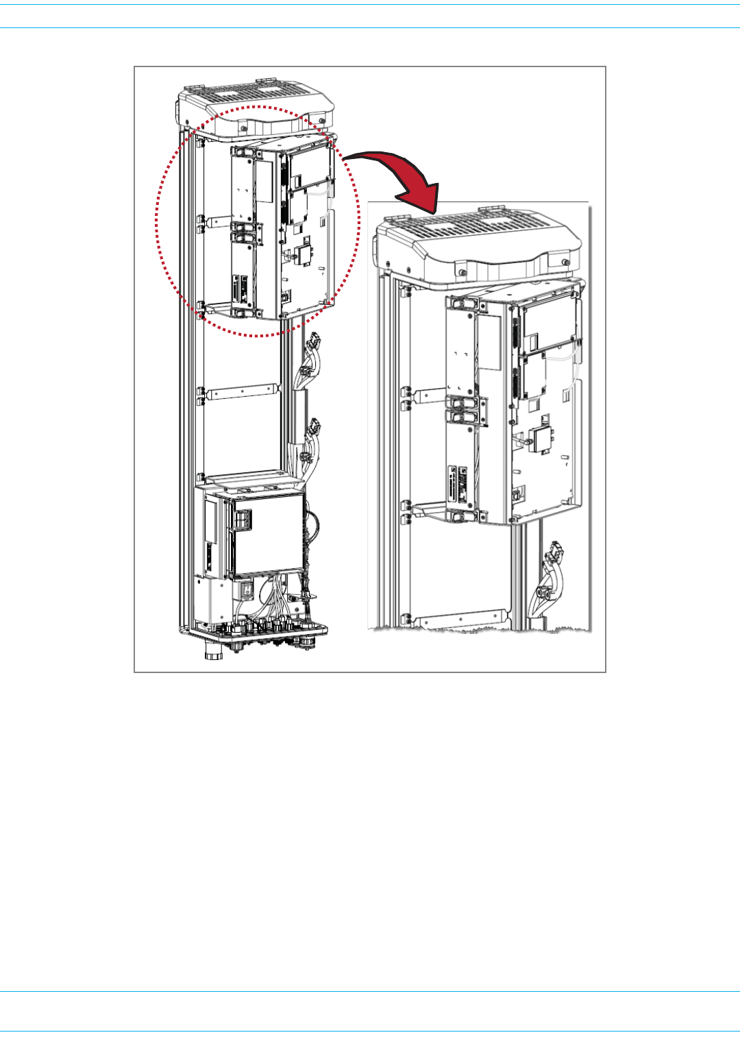
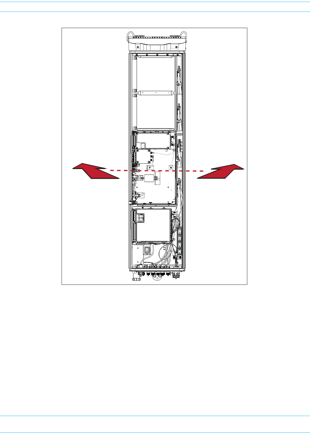
3AligntheMountingHookonthemodulewiththereceivingflangeonthePRUheatsink,andthen
slidetheRFModuleintowardtheflangeuntilitcangonofurther.
4PushtheleftedgeoftheRFModulebackandintothePRUchassisuntilitcangonofurther,asshown
inthefollowinggraphics:
•ForSingle-BayRFModules,seeFigure25onpage91.
•ForHDMRFModules,seeFigure26onpage92.
•ForDual-BayRFModules,seeFigure27onpage93,whichusestheLegacyDual-Bay40WRF
Moduleasanexample.
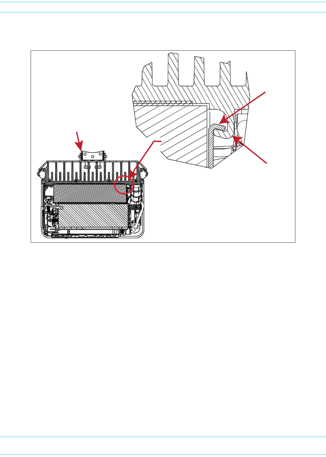
CAUTION! Make sure the RF Module is seated correctly in the Module shelf. Incorrect alignment of the
RF Module can cause the RF Module to fail due to overheating.
• The front edge of the RF Module should be parallel with the shelf above it.
• The Mounting Hook on the RF Module should be fully engaged with the Receiving flange
on the Remote Unit chassis.
• An incorrectly seated RF Module makes closing the Prism door difficult. If you later cannot
shut the Remote Unit door, verify that the RF Module is installed correctly.
RF Module
MounƟng
hook
Chassis
Receiving
flange
MounƟng Bracket at
back of the PRU
(View is looking down into the
PRU chassis from the top.)
FWPP-501-01 Issue 1 • 320000117795 Rev A FlexWave Prism Remote Unit and HDM RF Module Installation Guide
© March 2016 CommScope, Inc. Page 91
Install the RF Module(s)
Figure 25. Seating a Single-Bay RF Module
Push the RF Module
back into the chassis
unƟl it can go no further.
Single-Slot
RF Module
FlexWave Prism Remote Unit and HDM RF Module Installation Guide 320000117795 Rev A • FWPP-501-01 Issue 1
Page 92 © March 2016 CommScope, Inc.
Install the RF Module(s)
Figure 26. Seating an HDM RF Module
Push the HDM RF Module
back into the chassis
unƟl it can go no further.
HDM
RF
Module
FWPP-501-01 Issue 1 • 320000117795 Rev A FlexWave Prism Remote Unit and HDM RF Module Installation Guide
© March 2016 CommScope, Inc. Page 93
Install the RF Module(s)
Figure 27. Seating a Dual-Bay RF Module
Push the RF Module back
into the chassis unƟl it can
go no further.
FlexWave Prism Remote Unit and HDM RF Module Installation Guide 320000117795 Rev A • FWPP-501-01 Issue 1
Page 94 © March 2016 CommScope, Inc.
Install the RF Module(s)
SECURE RF MODULE LATCHES
TosecurethemodulelatchesontheleftsideoftheRFModule,dooneofthefollowing,asappropriate
fortheRFModulebeinginstalled:
•"ConnectLatchesonSingle-BayandHDMRFModules”onpage94
•"ConnectLatchesonDual-BayRFModules”onpage95.
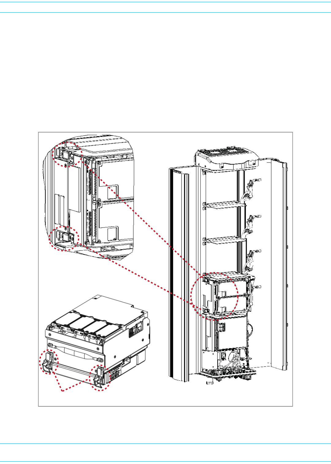
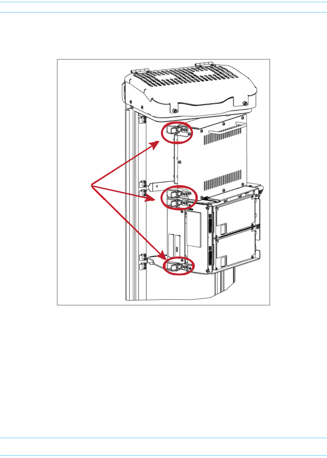
Connect Latches on Single-Bay and HDM RF Modules
ForSingle-BayandHDMRFModules,securetwolatches,asshowninFigure28.
Figure 28. Latches on Single-Bay and HDM RF Modules
Two latches on
Single-Slot
RF Modules
Two latches on
HDM RF Modules
FWPP-501-01 Issue 1 • 320000117795 Rev A FlexWave Prism Remote Unit and HDM RF Module Installation Guide
© March 2016 CommScope, Inc. Page 95
Install the RF Module(s)
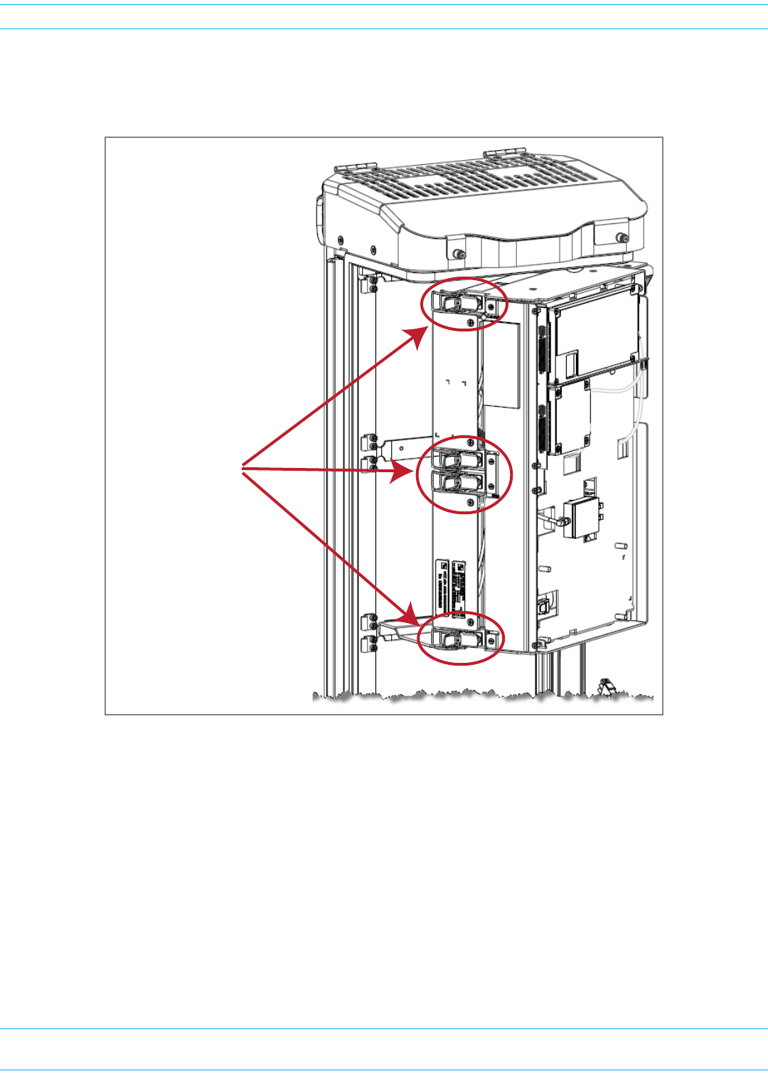
Connect Latches on Dual-Bay RF Modules
ForDual-BayRFModules,securefourlatches,asshowninFigure29.
Figure 29. Dual-Bay RF Module Latches
Four latches
in a
Dual-Band
Dual-Slot
RF Module
FlexWave Prism Remote Unit and HDM RF Module Installation Guide 320000117795 Rev A • FWPP-501-01 Issue 1
Page 96 © March 2016 CommScope, Inc.
Install the RF Module(s)
Latches on Legacy Dual-Bay 40W RF Modules
ForLegacyDual-Bay40WRFModules,securefourlatches,asshowninFigure30.
Figure 30. Legacy Dual-Bay 40W RF Module Latches
Verify that the RF Module Mounting Hook is Engaged
VerifythattheRFModuleMountingHookisengagedcorrectlybypullingthemoduleawayfromthe
heatsink.TheRFModuleshouldnotmove.IftheRFModulemovesduringthischeck,repeatallthe
stepsstartingat"InstalltheRFModuleintothePrismRemoteChassis”onpage86throughthisstep.
Four latches in a
Legacy Dual-Slot 40W
RF Module

FWPP-501-01 Issue 1 • 320000117795 Rev A FlexWave Prism Remote Unit and HDM RF Module Installation Guide
© March 2016 CommScope, Inc. Page 97
Install the RF Module(s)
CONNECT THE RF MODULE CABLES TO THE PRU CHASSIS
ThestepstoconnecttheRFModulecableshavebeenseparatedintotwodifferentprocedures;follow
thestepsthatcorrespondtotheRFModulebeinginstalled.
•"ConnectingCablesinaSingle-BayRFModuleInstallation”onpage97
•"ConnectingCablesinaDual-BayRFModuleInstallation”onpage100.
Connecting Cables in a Single-Bay RF Module Installation
1PositionthecablessothattheyareundertherightedgeoftheRFModule,pointingup.
2Followtheruleslistedin"UnderstandingRFCableRules”onpage26.
3ConnecttheRFModulecables,intheordershownbelow.Asyouwork,refertothegraphicthat
correspondstotheRFModulebeinginstalledintoasinglebayofthePRU:foraSingle-BayRF
Module,refertoFigure31onpage98,andforanHDMRFModule,refertoFigure32onpage99and
Table24onpage99.
aConnecttheMODNTX0/RX0cabletotheRFModule(theRFcablesandconnectorsarereferred
toasMODNTX0/RX0whereNequalsA,B,C,orD).
iInserttheN-StylePlugoftheMODNTX0/RX0cableintotheTX0/RX0N-StyleJackoftheRF
Module.
ii Turnthecouplingnutoftheplugclockwisetothreadontothejackandfinger-tighten.
iii Torquecouplingnutto8±1in-lbstoensurefullconnection.
NOTE: Insufficient torque applied to RF Module connections can result in elevated insertion/return
loss and higher than normal VSWR reported by the system.
bConnecttheMODNTX1/RX1cabletotheRFModule(theRFcablesandconnectorsarereferred
toasMODNTX1/RX1whereNequalsB,C,orD).
iIfaTX1/RX1RFModuleconnectionisavailable,inserttheN-StylePlugoftheMODN
TX1/RX1cableintotheTX1/RX1N-StyleJackoftheRFModule.IfRFModuleconnectionis
notavailable,constraintheMODNTX1/RX1cabletoaccompanyingcablesusingatiewrap
soitcannotbepinchedorpreventtheRemoteUnitdoorfromclosing.
ii Turnthecouplingnutoftheplugclockwisetothreadontothejackandfinger-tighten.
iii Torquecouplingnutto8±1in-lbstoensurefullconnection.
NOTE: Insufficient torque applied to RF Module connections can result in elevated insertion/return
loss and higher than normal VSWR reported by the system.
FlexWave Prism Remote Unit and HDM RF Module Installation Guide 320000117795 Rev A • FWPP-501-01 Issue 1
Page 98 © March 2016 CommScope, Inc.
Install the RF Module(s)
Figure 31. Cable Connections for Single-Bay RF Modules
CAUTION! Ensure that all cable bends are below the top edge of the Connector Interface Panel as
indicated by the dashed line in the preceding figure. Failure to correctly position the cables
could inhibit closing the Remote Unit door, which can result in damage to the cables.
Bay A
Bay D
Bay C
Bay B
SeRF
Module
TX0/RX0
TX1/RX1
DIV
PRIM
PWR
Note rouƟng of
high-speed cables
Note bend
radii ≥ 1-inch
Edge of Connector Interface Panel
Cable connecƟons for a Single-Slot RF Module
FWPP-501-01 Issue 1 • 320000117795 Rev A FlexWave Prism Remote Unit and HDM RF Module Installation Guide
© March 2016 CommScope, Inc. Page 99
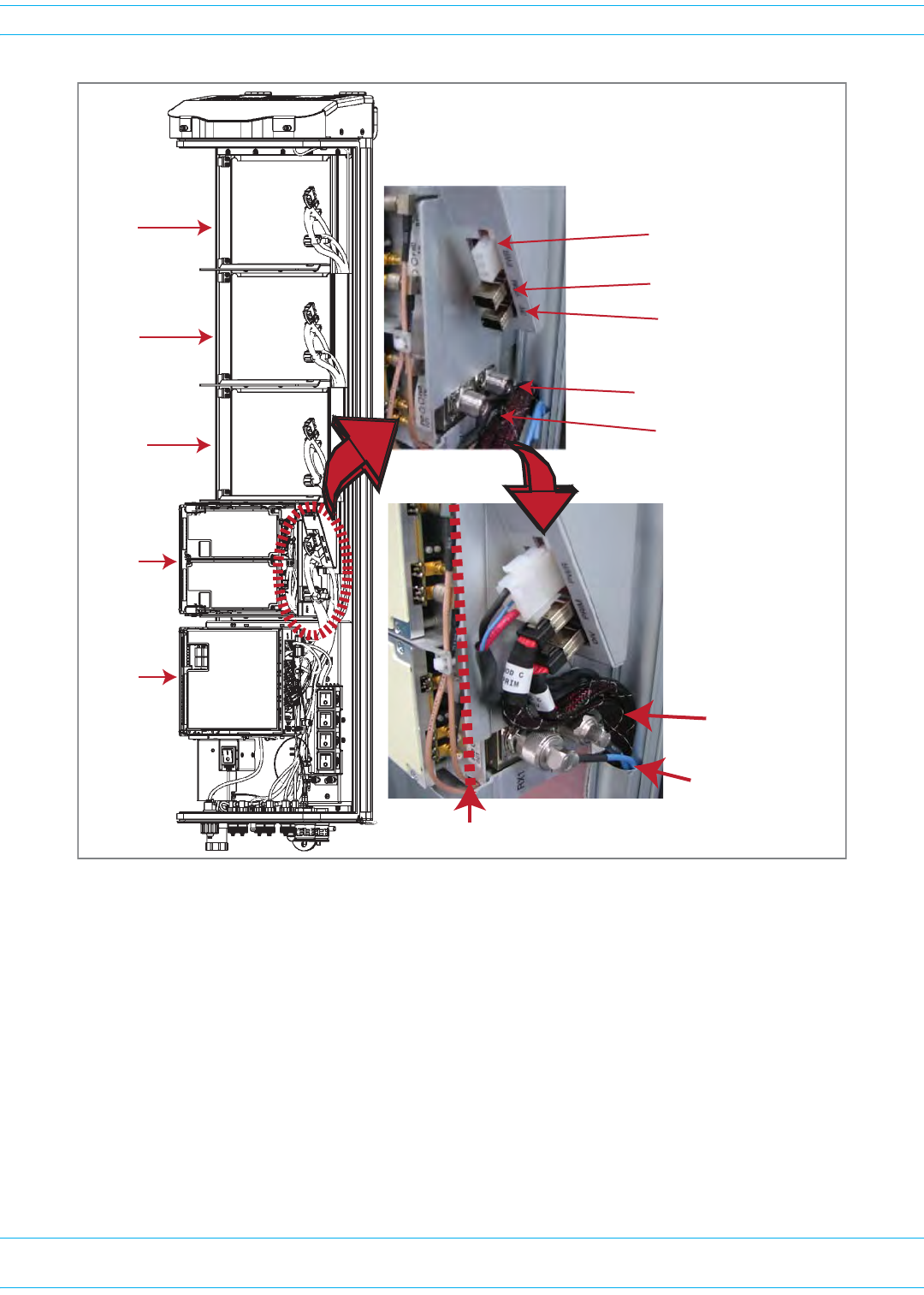
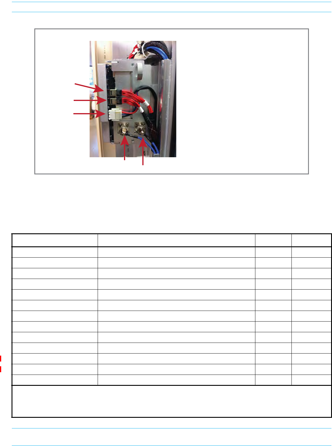
Install the RF Module(s)
Figure 32. Cable Connections for HDM RF Modules
Table24listshowtocorrectlyconnectHDMRFModulestotheAntennaportsonthebottomofthe
RemoteUnit.
Table 24. HDM Antenna Port Mapping
RF Module Catalog # Description TX0/RX0 TX1/RX1
FWP-L4MT000MOD 20W 700 LABC Module, MIMO HDM, Single-Bay Path 1 Path 2
FWP-U4MT000MOD 20W 700 uC Module, MIMO HDM, Single-Bay Path 1 Path 2
FWP-L4MTU4MMOD 20W 700 LABC/700uC, Dual, Single-Bay 700 LABC 700 uC
FWP-44MT000MOD 20W 800 MIMO, Single Bay, with two External Filters Path 1 Path 2
FWP-441T841MOD (1) 20W 800 SMR/ 1900 PCS, Dual RF Module 1900 800
FWP-B4MT000MOD 20W 850 DUAL, MIMO, Single Bay Path 1 Path 2
FWP-C4MT000MOD 20W 850 Cell/1900 PCS, Dual, Single-Bay 1900 850
FWP-84MT000MOD 20W 1900 PCS Dual MIMO, Single-Bay Path 1 Path 2
FWP-84MTA4MMOD 20W 1900/2100 Dual, Single Bay 2100 1900
FWP-W4MT000MOD 20W 2300 WCS FDD, MIMO Path 1 Path 2
FWP-T4MT000MOD-L 20W 2500 TDD Low, MIMO Path 1 Path 2
FWP-T4ST000MOD-H 20W 2500 TDD High, SISO, 2615-2690 Path 1 NA
FWP-A4MT000MOD 20W HDM AWS Band 4 MIMO, Single-Bay Path 1 Path 2
(1) A 20W 800 SMR/ 1900 PCS, Dual RF Module RF Module (FWP-441T841MOD) requires a FlexWave Notch Filter
(FWP-SPRINTFILTER) between the Remote Unit and the antenna to provide protection from spurious emissions in the Public
Safety band below 861.35 MHz and the Cellular band above 869.5 MHz. Information on how to install the Notch Filter is provided
in "FlexWave Notch Filter (FWP-SPRINTFILTER)” on page 108.
Cable ConnecƟons for an HDM RF Module
TX0/RX0
TX1/RX1
POWER
DATA 1 (DIV)
DATA 0 (PRIM)
Cable ConnecƟon Notes
• Always connect the Power cable.
• Always connect the two LVDS cables: PRIM and DIV.
• SISO requires one RF cable (TX0/RX0).
• MIMO and Dual-Band require two RF cables
(TX1/RX1 and TX0/RX0).

FlexWave Prism Remote Unit and HDM RF Module Installation Guide 320000117795 Rev A • FWPP-501-01 Issue 1
Page 100 © March 2016 CommScope, Inc.
Install the RF Module(s)
cConnecttheLVDSCablestotheRFModule—theLVDScableslabeledPRIMandDIVshould
alwayseitherbeconnectedtoaRFModuleorstrainrelievedtoadjacentcables,asthisprotects
thecableagainstdamagethroughmisplacement.Maintainadequatestrain-reliefdistancesfrom
theconnectionpointstotheRFModule.
iConnecttheMODNDIVLVDSCabletotheDIVreceptacleoftheRFModulebyinsertingand
slidinginuntilfullyseated.FullinsertioncanberecognizedbyanaudibleclickastheLVDS
CableConnectorlocksintotheRFModuleReceptacle.
ii ConnecttheMODNPRIMLVDSCabletothePRIMconnector,followingthesamestepsas
above.FullinsertioncanberecognizedbyanaudibleclickastheLVDSCableConnectorlocks
intotheRFModuleReceptacle.
iii EnsurethetwoLVDScablesarefullyseatedandlatchedintotheirrespectivereceptacleson
theRFModulebylightlypullingoutwardontheconnectors.Iffullyseatedandlockedinto
position,thecableconnectorswillnotslidebackout.
dConnectthePowercabletothePWRreceptacleoftheRFModule.
iEnsurethattheDCpowerswitchthatcorrespondstothebay(s)inwhichtheRFModuleisto
beinstalledisintheOffposition(see"ChecktheDCPowerSwitchfortheModuleBay”on
page84).
iInsertthePowercableintothePWRconnector,andslideitinuntilfullyseated.Fullinsertion
canberecognizedbyanaudibleclickasthePowercableConnectorlocksintotheRFModule
Receptacle.
ii VerifythatthePowercableisfullyseatedbylightlypullingbackonitwhilemakingsureto
notdepressthereleasetriggersontheendsoftheconnector.Whenfullyinserted,thecable
shouldnotbeabletoberemovedfromthereceptacle.
CAUTION! Maintain adequate strain relief distances from the connection points to the RF Module.
4Repeatallthestepsin"InstalltheRFModule(s)”onpage80toinstallotherRFModules.
Connecting Cables in a Dual-Bay RF Module Installation
1PositionthecablessothattheyareundertherightedgeoftheRFModule,pointingup.
2Followtheruleslistedin"UnderstandingRFCableRules”onpage26.

FWPP-501-01 Issue 1 • 320000117795 Rev A FlexWave Prism Remote Unit and HDM RF Module Installation Guide
© March 2016 CommScope, Inc. Page 101
Install the RF Module(s)
3ConnecttheRFModulecables,workingfromthebottomconnectorup,asdescribedbelow.
Asyouwork,refertothegraphicthatcorrespondstotheRFModulebeinginstalledintheDual-Bay:
foraDual-BayRFModule,refertoFigure33onpage102,andforaLegacyDual-Bay40WRF
Module,refertoFigure34onpage103.
aConnecttheMODNTX1/RX1cabletotheN-StyleRFconnectorontheDual-BayRFModule(the
RFcablesandconnectorsarereferredtoasMODNTX1/RX1whereNequalsB,C,orD).
iConstraintheMODNTX1/RX1cableofthelowerRFModulebaytoaccompanyingcables
usingatiewrapsoitcannotbepinchedorpreventtheRemoteUnitdoorfromclosing.
ii ConnecttheMODNTX1/RX1cabletotheTX1/RX1N-StyleJackoftheupperRFModuleBay.
iii Turnthecouplingnutoftheplugclockwisetothreadontothejackandfinger-tighten.
iv Torquecouplingnutto8±1in-lbstoensurefullconnection.
NOTE: Insufficient torque applied to RF Module connections can result in elevated insertion/return
loss and higher than normal VSWR reported by the system.
FlexWave Prism Remote Unit and HDM RF Module Installation Guide 320000117795 Rev A • FWPP-501-01 Issue 1
Page 102 © March 2016 CommScope, Inc.
Install the RF Module(s)
Figure 33. Cable Connections for Dual-Band Dual-Bay RF Modules
Cable ConnecƟons for a Dual-Slot RF Module
Tie wrap
Factory-installed
RX1 cable
Two N-Type
RF connectors
N-Type
RF connector
FWPP-501-01 Issue 1 • 320000117795 Rev A FlexWave Prism Remote Unit and HDM RF Module Installation Guide
© March 2016 CommScope, Inc. Page 103
Install the RF Module(s)
Figure 34. Cable Connections for Legacy Dual-Bay 40W RF Modules
CAUTION! Ensure that all cable bends are below the top edge of the Connector Interface Panel as
indicated by the dashed line in the preceding figure. Failure to correctly position the cables
could inhibit closing the Remote Unit door, which can result in damage to the cables.
bConnecttheMODNTX0/RX0cabletotheRFModule(theRFcablesandconnectorsarereferred
toasMODNTX0/RX0whereNequalsA,B,C,orD).
iInserttheN-StylePlugoftheMODNTX0/RX0cableintotheTX0/RX0N-StyleJackofthe
lowerRFModulebay.IfRFModuleconnectionisnotavailable,constraintheMODN
TX0/RX0cabletoaccompanyingcablesusingatiewrapsoitcannotbepinchedorprevent
theRemoteUnitdoorfromclosing.
ii Turnthecouplingnutoftheplugclockwisetothreadontothejackandfinger-tighten.
iii Torquecouplingnutto8±1in-lbstoensurefullconnection.
NOTE: Insufficient torque applied to RF Module connections can result in elevated insertion/return
loss and higher than normal VSWR reported by the system.
Tie wrap around
factory-installed
RX1 cable
Keep cable bends
behind the edge
of the Connector
Interface Panel

FlexWave Prism Remote Unit and HDM RF Module Installation Guide 320000117795 Rev A • FWPP-501-01 Issue 1
Page 104 © March 2016 CommScope, Inc.
Install the RF Module(s)
cConnecttheLVDSCablestotheRFModule—theLVDScableslabeledPRIMandDIVshould
alwayseitherbeconnectedtoaRFModuleorstrainrelievedtoadjacentcables,asthisprotects
thecableagainstdamagethroughmisplacement.Maintainadequatestrain-reliefdistancesfrom
theconnectionpointstotheRFModule.
iConnecttheMODNDIVLVDSCabletotheDIVreceptacleoftheRFModulebyinsertingand
slidinginuntilfullyseated.FullinsertioncanberecognizedbyanaudibleclickastheLVDS
CableConnectorlocksintotheRFModuleReceptacle.
ii ConnecttheMODNPRIMLVDSCabletothePRIMconnector,followingthesamestepsas
above.FullinsertioncanberecognizedbyanaudibleclickastheLVDSCableConnectorlocks
intotheRFModuleReceptacle.
iii EnsurethetwoLVDScablesarefullyseatedandlatchedintotheirrespectivereceptacleson
theRFModulebylightlypullingoutwardontheconnectors.Iffullyseatedandlockedinto
position,thecableconnectorswillnotslidebackout.
dConnectthePowercabletothePWRreceptacleoftheRFModule.
iEnsurethattheDCpowerswitchthatcorrespondstothebay(s)inwhichtheRFModuleisto
beinstalledisintheOffposition(see"ChecktheDCPowerSwitchfortheModuleBay”on
page84).
ii InsertthePowercableintothePWRreceptacleofthelowerRFModulebay,andslideitin
untilfullyseated.FullinsertioncanberecognizedbyanaudibleclickasthePowercable
ConnectorlocksintotheRFModuleReceptacle.
iInsertthePowercableintothePWRreceptacleoftheupperRFModulebay,andslideitin
untilfullyseated.FullinsertioncanberecognizedbyanaudibleclickasthePowercable
ConnectorlocksintotheRFModuleReceptacle.IfthePWRreceptacleisnotavailable,
constrainthePowercabletoaccompanyingcablesusingatiewrapsoitcannotbepinched
orpreventtheRemoteUnitdoorfromclosing.
ii VerifythatthePowercableisfullyseatedbylightlypullingbackonitwhilemakingsureto
notdepressthereleasetriggersontheendsoftheconnector.Whenfullyinserted,thecable
shouldnotbeabletoberemovedfromthereceptacle.
4Repeatallthestepsin"InstalltheRFModule(s)”onpage80toinstallotherRFModules.
FWPP-501-01 Issue 1 • 320000117795 Rev A FlexWave Prism Remote Unit and HDM RF Module Installation Guide
© March 2016 CommScope, Inc. Page 105
Install the RF Module(s)
POWER ON THE RF MODULE(S) AND THE PRISM REMOTE UNIT
1Ifnecessary,poweruptheRemoteUnitbyturningitsACorDCpowerswitchtoOn.
2EnsurethattheexternalStatusLEDonthebottomoftheRemoteUnitgoesoff.(Atsystemstartup,
theStatusLEDisredtoindicatethattheRemoteUnitispoweringupandthattheSeRFprocessor
doesnotyetcontroltheRemoteUnit;theStatusLEDwillremainredfornomorethan4minutes;
forfurtherinformationsee"RemoteUnitStatusLED”onpage10.)
NOTE: The preceding graphic illustrates the Status LED on a Quad-Bay PRU. The Status LED for the
Single-Bay, Dual-Bay, and Tri-Bay PRUs is in the same location and functions the same as the
Status LED for the Quad-Bay PRU.
BoƩom of an AC-Powered PRU BoƩom of a DC-Powered PRU
Status LED
NETWORK
POWER
48VDC/XXA
MOD D
TX1/RX1
NETWORK
MOD D
TX1/RX1
POWER
100-240 VAC
50-60 Hz
XX AMPS
WARNING:
HIGH LEAKAGE CURRENT. EARTH
CONNECTION ESSENTIAL BEFORE
CONNECTING SUPPLY
MOD D
TX0/RX0
MOD D
TX0/RX0
FlexWave Prism Remote Unit and HDM RF Module Installation Guide 320000117795 Rev A • FWPP-501-01 Issue 1
Page 106 © March 2016 CommScope, Inc.
Install the RF Module(s)
3FollowtheruleslistedbelowtotogglethePowerswitchthatcorrespondstoeachRFModuletoits
ONposition.
•ForDual-BandDual-BayRFModules,usethePowerswitchforthelowermodule.Forexample,
topowerupaDual-BayRFModuleincombinedbaysC+DinaQuad-Baychassis,turnONDC
PowerswitchforModC;leavetheDCPowerswitchforModDOFF.
•ALegacyDual-Bay40WRFModuleusesthePowerSuppliesinbothbays.IftheLegacyDual-Bay
40WRFModuleisinstalledinbaysC+D,turnONthePowerswitchforModCandModD.
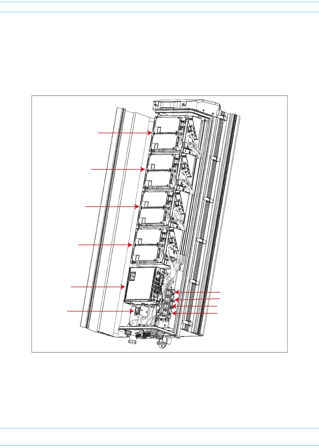
4VerifythattheLEDsforallinstalledRFModules(locatednexttotheirrespectiveconnectors)are
green.IfanyoftheRFModuleLEDsarenotgreen,verifythateachRFModulecableisseatedfullyin
itsrespectiveconnector.IfaftercheckingthecableconnectionsandanLEDisnotgreen,contact
CommScopeforassistance(see"DCCSGlobalTechnicalSupport”onpage119).
ForfurtherinformationonStatusLEDsonHDMRFModules,see"LEDSonNarrowbandHDMRF
Modules”onpage21and"LEDSonWidebandandFullbandHDMRFModules”onpage22.
Bay A
SeRF Module
AC/DC Power
switch for
PRU chassis DC Power switch for Bay A
DC Power switch for Bay B
DC Power switch for Bay C
DC Power switch for Bay D
Bay B
Bay C
Bay D
FWPP-501-01 Issue 1 • 320000117795 Rev A FlexWave Prism Remote Unit and HDM RF Module Installation Guide
© March 2016 CommScope, Inc. Page 107
Install the RF Module(s)
CLOSE THE REMOTE UNIT DOOR AND SOLAR SHIELD
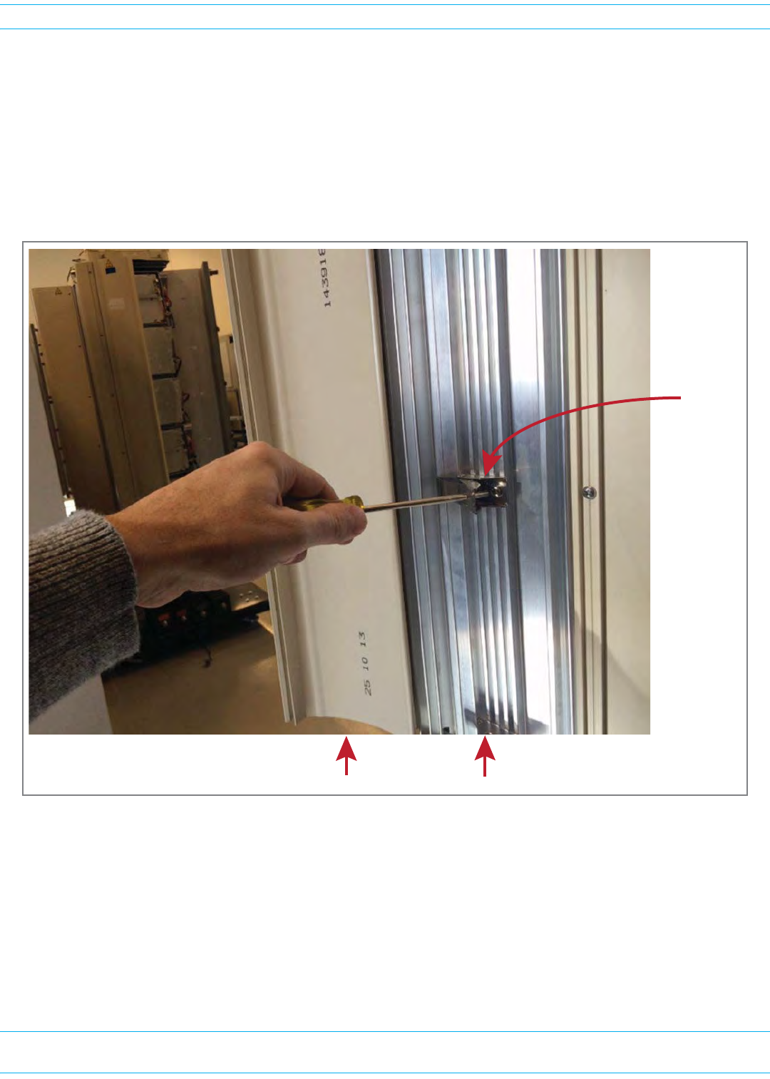
1Donotslamthedoortocloseit—gentlyswingthedoorshutandpressitfirmlyclosed.
2Slowlycloseeachdoorlatchinasmoothfluidmotion—donotallowthedoorlatchestosnapclosed.
Forbestresults,startingwiththetoplatchandworkingdowntothebottomlatch,useaflat-head
screwdrivertocloseeachlatchasshownbelow.
3DonotslamtheSolarShieldtocloseit—gentlyswingitshutandpressitfirmlyclosed.
CAUTION! Service personnel must confirm that the perimeter gasket and door-to-door gaskets are in
place when closing the Remote Unit doors after servicing.
CAUTION! If the PRU door was allowed to snap closed, RF output from an HDM RF Module may be
disabled for up to three minutes. Any alarms generated immediately following the
opening/closing of the PRU Doors, such as Door Open, RF Power Low, System VSWR Fault, and
LPA VSWR Fault, automatically clear once the RF has recovered. If alarms do not clear after
three minutes, please contact CommScope for technical support; see "DCCSGlobalTechnical
Support”onpage119.
Solar Shield Door
Door latch

FlexWave Prism Remote Unit and HDM RF Module Installation Guide 320000117795 Rev A • FWPP-501-01 Issue 1
Page 108 © March 2016 CommScope, Inc.
FlexWave Notch Filter (FWP-SPRINTFILTER)
PROVISION THE PRISM REMOTE UNIT
RefertothecurrentEMSSystemSetupandProvisioningGuideforinformationonconfiguringthePRU
foraFlexWavePrismsystem.
FLEXWAVE NOTCH FILTER (FWP-SPRINTFILTER)
AFlexWaveNotchFilter(FWP-SPRINTFILTER)shipswithandisrequiredininstallationsofthe
followingRFModules:
•Dual20WSMR800/PCS1900RFModule(FWP-441T841MOD)
•Dual20W800RFModule,MIMO,SingleBay,withtwoExternalFilters(FWP-44MT000MOD).
YouinstalltheNotchFilterbetweenthePrismRemoteUnitandtheantennatoprovideprotectionfrom
spuriousemissionsinthePublicSafetybandbelow861.35MHzandtheCellularbandabove869.5MHz.
YouusethesamemountingmethodstomounttheNotchFilterasyouusedtomountthePRU.Takethe
followingintoconsiderationwhenplanningtheinstallation:
•TheNotchFilteranditsmountingbracketsrequires19inchesofverticalspaceabovethePRU(see
Figure35andFigure36onpage110).
•TheNotchFilterweighs18pounds;makesuretheinstallationsitecanbearthisadditionalweight.
•MounttheNotchFilterverticallywiththeN-typefemaleconnectorsatthebottom.
•TherearetwoGroundlugsontheNotchFilter,whichareonthebackofthetwomountingbrackets.
FollowlocalpracticetogroundtheNotchFilter.
•Thenotchfiltermustbeconnectedtothe800bandmoduleoutputbeforecombiningwithother
bandsorconnectingtoanantenna.
FWPP-501-01 Issue 1 • 320000117795 Rev A FlexWave Prism Remote Unit and HDM RF Module Installation Guide
© March 2016 CommScope, Inc. Page 109
FlexWave Notch Filter (FWP-SPRINTFILTER)
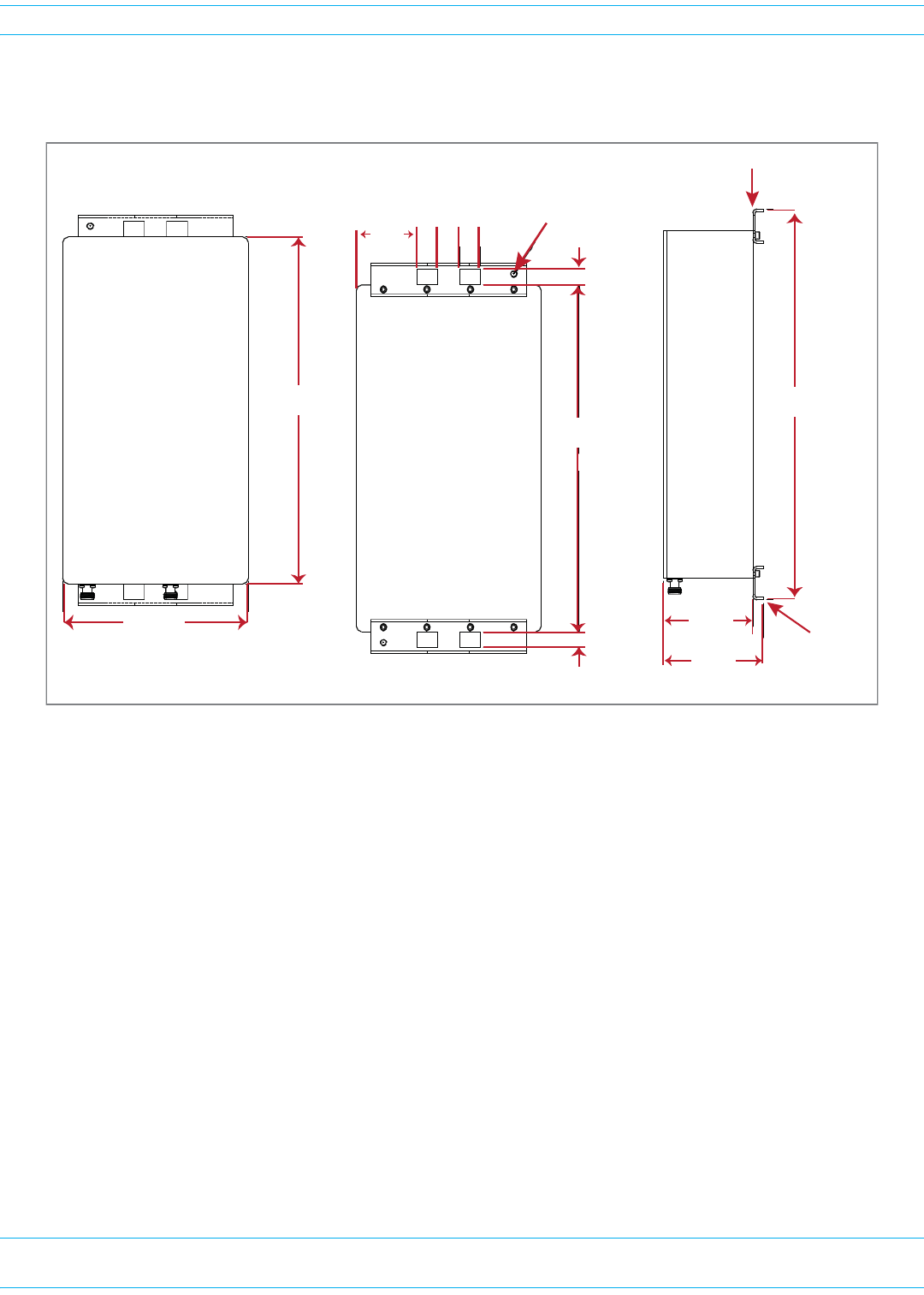
Figure35providesthedimensionsrequiredtocreateamountingtemplate.(Forfulltechnical
specifications,seeTable26onpage116.)
Figure 35. Notch Filter Mounting Dimensions
16.0 ±.1
.70
.70
2.805 .95 .95
1.00
2 LocaƟons
5/16-18
Ground Lug
Front View
Side View
Back View
4.55
17.9 ±.1
4.10
MounƟng
Bracket
15.93
8.51
MounƟng Bracket
FlexWave Prism Remote Unit and HDM RF Module Installation Guide 320000117795 Rev A • FWPP-501-01 Issue 1
Page 110 © March 2016 CommScope, Inc.
FlexWave Notch Filter (FWP-SPRINTFILTER)
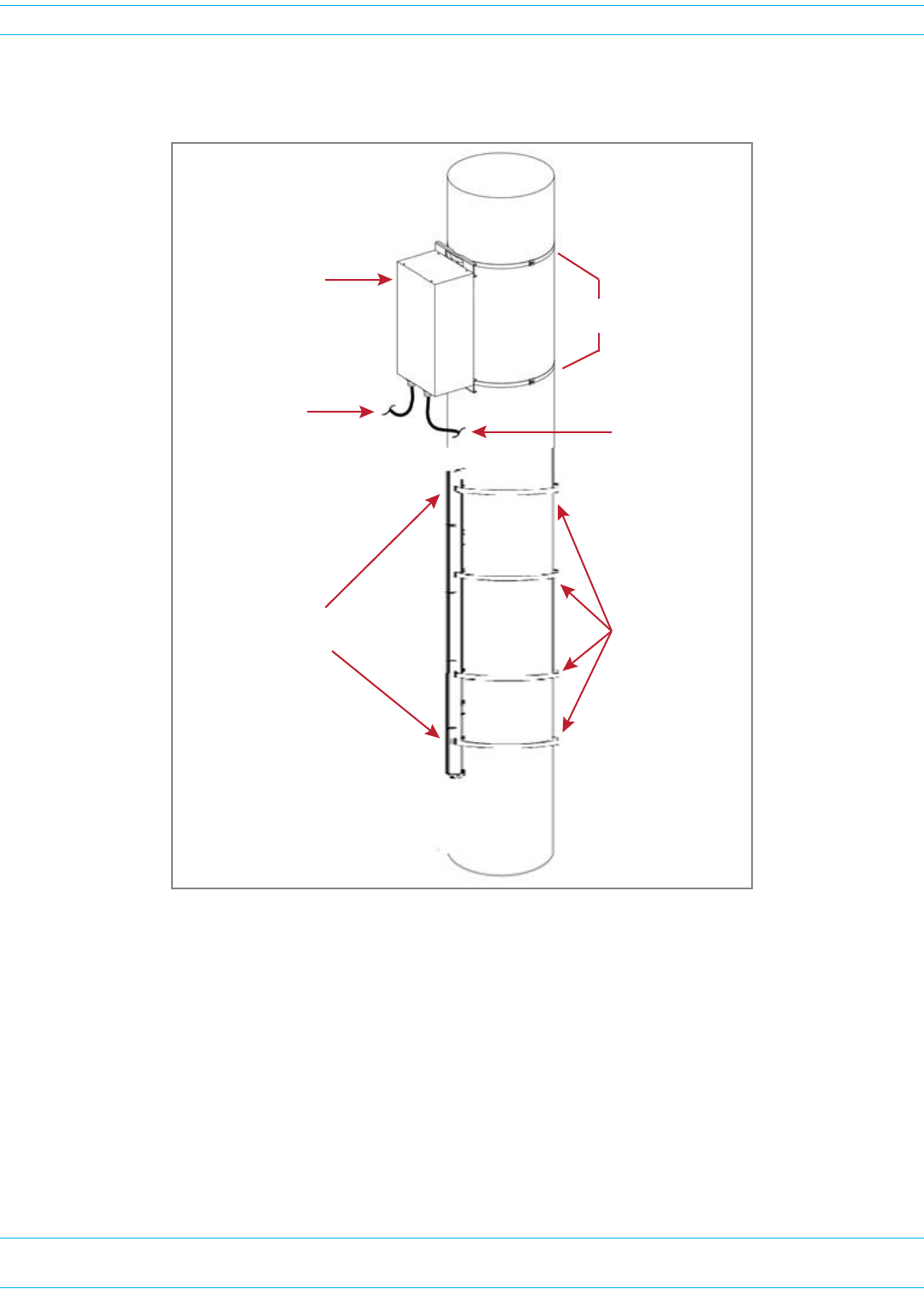
Figure37providesanexampleofhowthedimensionsrequiredtomounttheNotchFilterwitha
Quad-BayPRU.
Figure 36. Pole Mounting a Quad-Bay PRU with a Notch Filter
External Notch Filter
Bands for a
Quad-Bay PRU
From the Antenna
To the PRU Input
or Output port
19 inches of verƟcal space
to mount the Notch Filter
41.7” (105.918 cm)
Band 1 to BoƩom Band
FWPP-501-01 Issue 1 • 320000117795 Rev A FlexWave Prism Remote Unit and HDM RF Module Installation Guide
© March 2016 CommScope, Inc. Page 111
FlexWave Notch Filter (FWP-SPRINTFILTER)
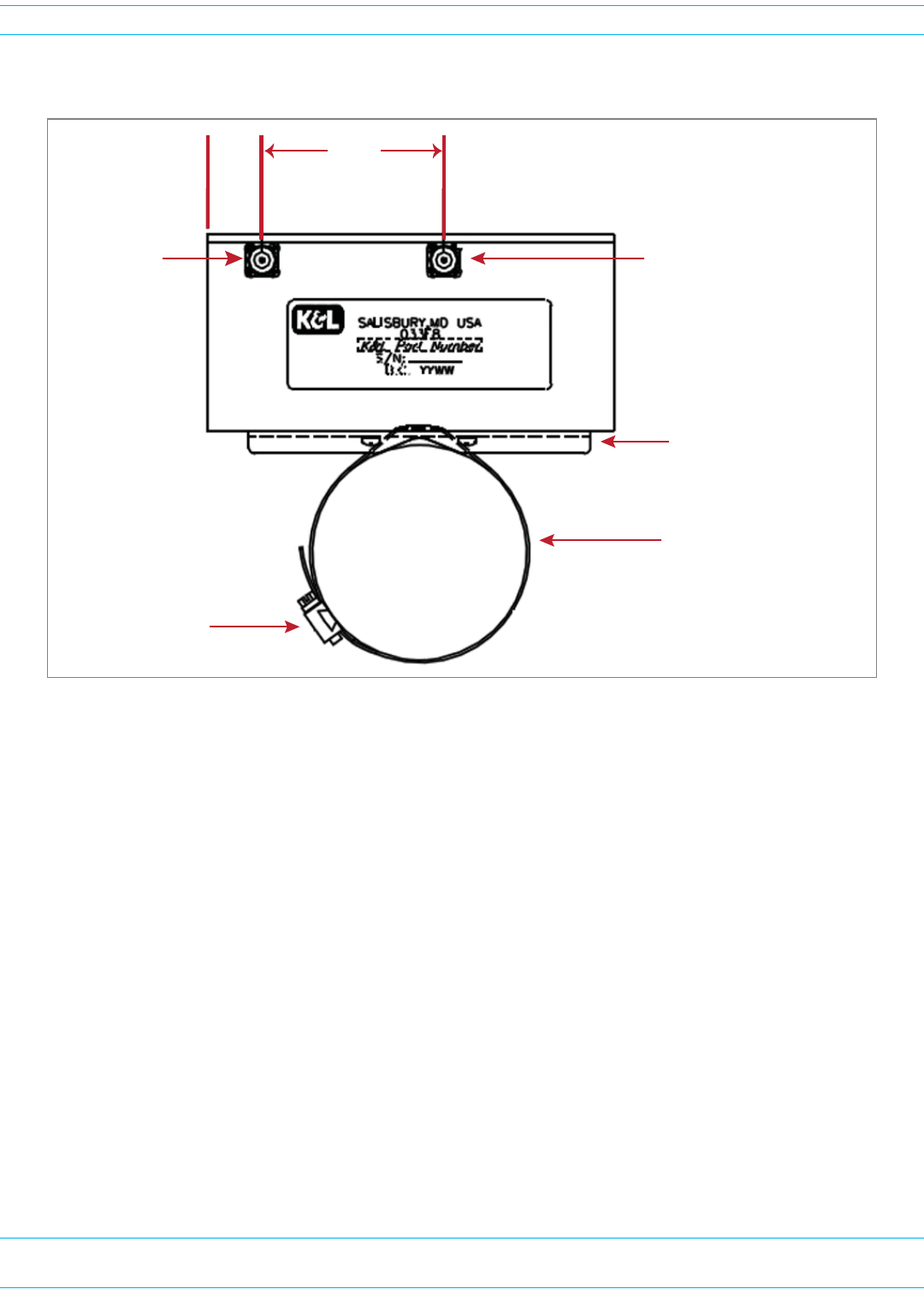
Figure37illustrateshowtopolemounttheNotchFilter.
Figure 37. Pole Mounting a Notch Filter
1.13 3.81
Input
N-Type
Female
Connector
Output
N-Type
Female
Connector
Band must be long enough
to wrap around the pole
BoƩom View of
Notch Filter
Hose clamp sized for
installaƟon requirement
MounƟng Bracket
NOTE: The 800 Notch Filter is
designed to accept input
from the PRU in either its
Output or Input port, as well
as the feed from the antenna.

FlexWave Prism Remote Unit and HDM RF Module Installation Guide 320000117795 Rev A • FWPP-501-01 Issue 1
Page 112 © March 2016 CommScope, Inc.
Fan Module Maintenance
FAN MODULE MAINTENANCE
ContinuousairflowtocoolthePRUisprovidedbytheFanModulethatismountedonthetopofthePRU
chassis.Thecoolingfanspulltheheatedairupfromthechassis.Theheatedairisthenexhausted
throughtheventopeningsatthetopofthechassis.ThisconstantmovementofairrequiresthattheFan
Modulebeplacedonamaintenanceschedule.
ANNUAL FAN CHECKUP
CAUTION! A mechanical hazard exists due to rotating fan blades. Keep hands and fingers away from fan
blades during removal of Fan Module. Use only the designated pull areas to disengage the fan
tray. Allow adequate time for fans to spin down prior to removal.
ChecktheFanModuleonanannualbasis.Inspecttheintakeandexhaustventsforobstructionsand/or
debris.Ifobstructionsand/ordebrisisobserved,removefromexteriorofsystemasnecessary.
POTENTIAL FAN ALARMS
ChecktheFanModuleshouldanyoneofthefollowingalarmsoccur:
•FanUnderSpeed(fwuRmtFanUnderSpeedFault)
•TemperatureHigh(fwuRmtOverTempFault)
•DARTTemperatureHigh(fwuRmtDARTOverTempFault)
•LPAOverTemperature(fwuRmtLPAHighTempFault)
REPLACING THE FAN MODULE
CAUTION! The rotating fan blades create a hazardous environment. Keep hands and fingers away from
the fan blades. Use only the designated pull areas to disengage the Fan Tray. Allow adequate
time for fans to spin down prior to removal.
CAUTION! Low voltage electrical shock hazard!
• Do not touch bare conductors or other potentially energized parts.
• Use appropriate safety equipment approved for use on electrical installations.
• Ensure fan module exterior of electrical connector and immediate area are clean and dry
prior to disconnection.
• Do not perform service during or while conditions of impending rain or snow are observed.
NOTE: You do not need to disconnect the power cabling from the Prism Remote Unit to replace the
Fan Module.
NOTE: If the PRU has an Enhanced Fan Shroud, refer to the FlexWave Prism Remote Unit Enhanced
Fan Shroud Installation Guide (TECP-77-235) for information on how to replace the Fan
Module.
FWPP-501-01 Issue 1 • 320000117795 Rev A FlexWave Prism Remote Unit and HDM RF Module Installation Guide
© March 2016 CommScope, Inc. Page 113
Fan Module Maintenance
UsethefollowingproceduretoremoveandreplacethePRUFanModule:
1ReadallinstructionsandproceduresofthissectionpriortobeginningworktoreplaceFanModule.
2OrderaPrismRemoteUnitFanReplacementKit,catalognumberFWP-RUFAN001.
3NotifytheNOCoralarmmonitoringsystemoperatorthattheFanModuleisbeingreplaced,which
willgeneratefanandpoweralarmsfortheaffectedPRU.
4PowerdownthePRUandwaituntilthefansspindowntoastop.
5PutonanESDwriststrapandensurethatitmakesmaximumcontactwithbareskinthroughoutthis
procedure.ESDgroundingstrapsareavailablewithbananaplugs,metalspringclips,oralligator
clips.Toensureadequategrounding,theESDwriststrapshouldbeconnectedtoanybaremetal
surfaceofthePRUchassis,ortotheDual-GroundConnectoratthebottomoftheunit.Forfurther
informationontheDual-GroundConnector,see"PortsandConnectors”onpage7.
NOTE: It may be necessary to scrape a small section of the coating off the Prism Remote Unit chassis
to ensure connection to a bare metal surface.
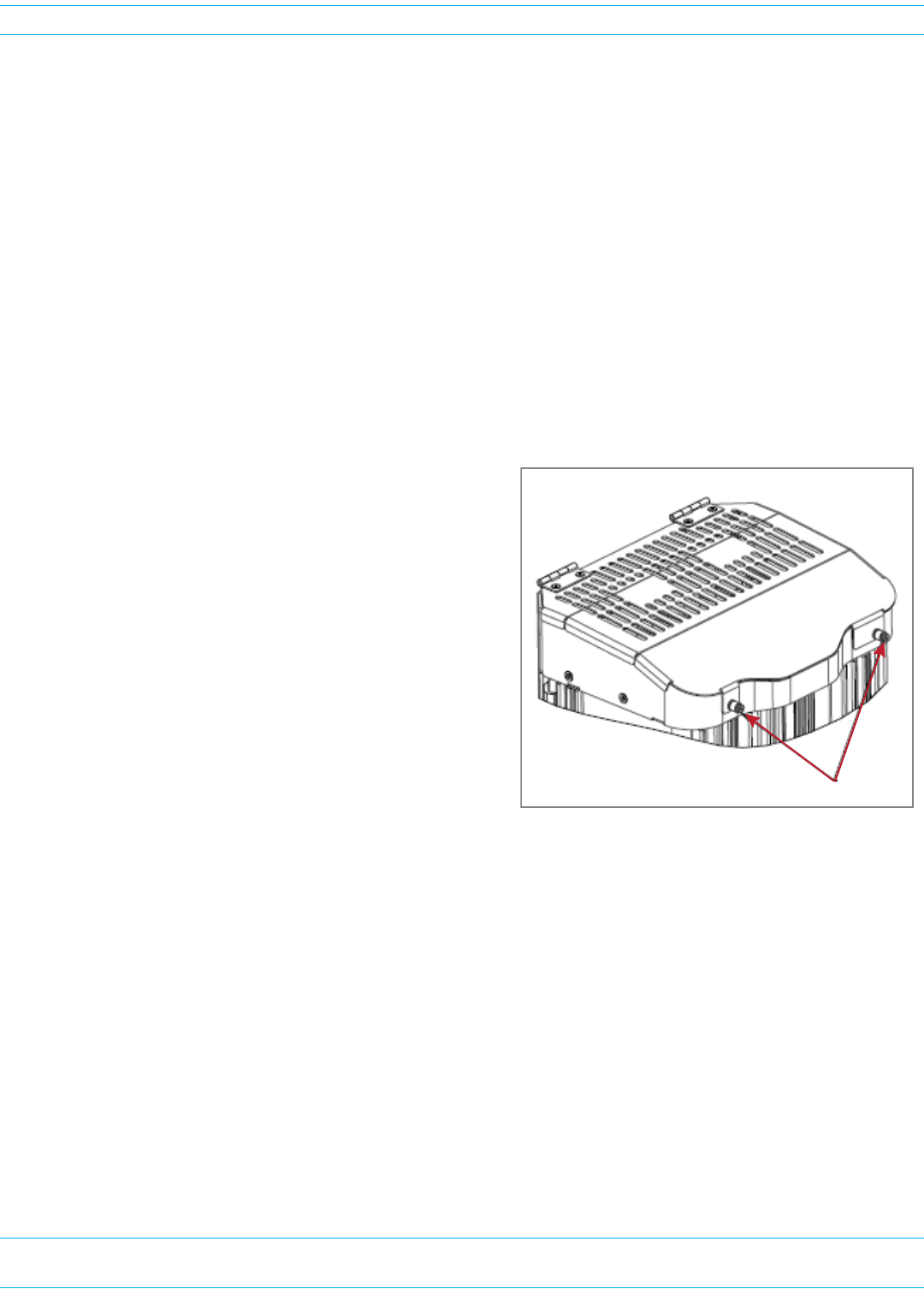
6LoosenthetwoscrewsthatsecuretheFanModule
CoveratthetopofthePRUchassistothefrontof
theenclosureasshowninthegraphictotheright.
7Openthefancoverbyrotatingitupandbackonits
hinges.
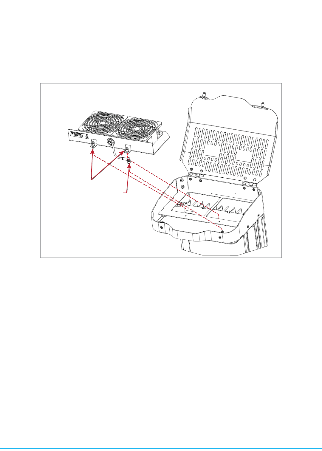
8DothefollowingbeforeyoulifttheFanModuleout
ofthePRUchassis:
aInspect,cleananddrythetopsurface
surroundingthefanconnector.
bLoosenthetwocaptivescrewsthatsecurethe
FanModuletothePRUchassis.
cDisconnecttheFanModulepowercableby
rotatingitscouplingnutcounter-clockwise
untilthereceptaclecanbeliftedoffits
bulkheadplug.
Two capƟve screws
Top of Prism Remote Unit
FlexWave Prism Remote Unit and HDM RF Module Installation Guide 320000117795 Rev A • FWPP-501-01 Issue 1
Page 114 © March 2016 CommScope, Inc.
Fan Module Maintenance
9RemovetheoldFanModulefromthePRU:
aTheFanModulehastwokeyholerivetsthatextendthroughtheirdesignatedslotsintothesheet
metalframe.TodisengagetheFanModulekeyholerivets,slidetheFanModuleforward
approximately1/4-inch.
bLifttheFanModulestraightuptoremoveitfromthePRUchassis.
10 LowertheFanModuleintothePRUfromthetop.EnsurethatthetwokeyholerivetsonthenewFan
Moduleextendthroughtheirdesignatedslotsinthesheetmetalframe,andthenslideFanModule
backapproximately1/4-inchtoengageitskeyholerivets.
11 AlignandtheninserttheFanModule’stwocaptivescrewswithnutsonthePRU;ensurecorrect
threadengagement,andthentightentheFanModule’scaptivescrews.
12 InserttheFanModulepowercablesothatthecableisdirectedtotheleftoftheconnector.Usethe
keytoalignthecablecorrectly.Donotuseexcessiveforcetomatethereceptacletotheplug.
CAUTION! Failure to align the Fan Module power cable correctly may cause damage to the PRU power
connectors, which could result in needing to replace the PRU chassis.
13 Useyourfingerstoturnthecouplingnutonthepowercableapproximately2-1/2revolutions,and
thentightenthecouplingnutanother1/4revolution.
14 TightenthetwocaptivescrewsthatsecuretheFanModuletothechassis;torquethescrewsto10
IN-LBS±1IN-LB.
15 ClosetheFanModulecoverandtightenitstwocaptivescrews;torquethescrewsto10IN-LBS±1
IN-LB.
Top of Prism Remote Unit
Two capƟve screws
Power cable

FWPP-501-01 Issue 1 • 320000117795 Rev A FlexWave Prism Remote Unit and HDM RF Module Installation Guide
© March 2016 CommScope, Inc. Page 115
Specifications
SPECIFICATIONS
ThefollowingspecificationspertaintothePRUhardwarecomponents;forinformationonRFand
opticalspecificationsandthefrequencyandcompositeoutputpowerattheAntennaport,seethe
FlexWavePrismPerformanceSpecificationsthatcorrespondtotheFlexWavesoftwarereleasemanaging
thisPRU.
Table 25. Prism Remote Unit Technical Specifications
Parameter Specification Remarks
Enclosure dimensions See Table 19 on page 31
Weight See Table 18 on page 31
Mounting Wall, Pole, Inside Pole, and Vault
Outside Ambient
Temperature Rating -40° C to +50° C (-40º F to +122º F)
Storage Temperature -40° C to +70° C (-40º F to +158º F)
Humidity 10% to 90% non-condensing
Weather Resistance IP-65 Indoor or outdoor installation
Lightning Protection 20kA IEC 1000-45 8/30 ìs Waveform Provided by external lightning protector,
which is an accessory.
Cooling Fan Fan, IP-55
Operating Voltage Range 10 - 28 Vdc
Connectors
Network port RJ-45 female connector
AC power connector Sealed 3-pin Connection point for the AC power cable
Antenna cable connector 50 ohm N-Type (female) 50 ohms input/output impedance
Voltage input
AC-Powered PRUs 100 to 240 Vac, 50 to 60 Hz Operating range 90 to 265 Vac
DC-Powered PRUs -40 to -60 Vdc
Current rating
AC-Powered PRUs 15 AMPS
DC-Powered PRUs 45 AMPS

FlexWave Prism Remote Unit and HDM RF Module Installation Guide 320000117795 Rev A • FWPP-501-01 Issue 1
Page 116 © March 2016 CommScope, Inc.
Specifications
Table 26. Notch Filter Specifications
Frequency Range (MHz) Maximum Emissions (Sprint requirement) per 30 kHz
817-824 —
< 854 < -76 dBm
854-859 < -76 dBm
859-861.35 < -76 dBm
861.35-861.5 < -56 dBm
861.5-861.6 < -42 dBm
862-869 —
Enclosure Rating IP67
RF Connectors N-Type Connector, Female (2)
Ground Studs (w/star washer) All ground Studs must accept AWG 6 wire
Mounting Strap mount (Vertical and Horizontal) on up to 12" pole, or Wall mount
Size 15.93" x 8.51" x 4.10"
Weight 18 LBS
Operational Temperature -25°C to +65°C
Humidity ETSI 300-019-1-3 10%-100% Condensing
Vibration-operation ETSI 300-019-1-4
Vibration-transportation ETSI 300-019-1-2

FWPP-501-01 Issue 1 • 320000117795 Rev A FlexWave Prism Remote Unit and HDM RF Module Installation Guide
© March 2016 CommScope, Inc. Page 117
Standards Certification
STANDARDS CERTIFICATION
FCC
ThisequipmentcomplieswiththeapplicablesectionsofTitle47CFRPart15(HostUnit),Part22(800
MHzCellular),Part24(1900MHz-PCS),Part90(800/900-SMR),andPart27(2100MHz-AWS)&
(700MHz-LTE).
WARNING.ThisisNOTaCONSUMERdevice.ItisdesignatedforinstallationbyFCCLICENSEESand
QUALIFIEDINSTALLERS.YouMUSThaveanFCCLICENSEorexpressConsentofanFCCLicenseeto
operatethisdevice.UnauthorizedusemayresultinSignificantforfeiturepenalties,includingpenalties
inexcessof$100,000foreachcontinuingviolation.
NOTE:ThisequipmenthasbeentestedandfoundtocomplywiththelimitsforaClassAdigitaldevice,
pursuanttopart15oftheFCCRules.Theselimitsaredesignedtoprovidereasonableprotectionagainst
harmfulinterferencewhentheequipmentisoperatedinacommercialenvironment.Thisequipment
generates,uses,andcanradiateradiofrequencyenergyand,ifnotinstalledandusedinaccordancewith
theinstructionmanual,maycauseharmfulinterferencetoradiocommunications.Operationofthis
equipmentinaresidentialareaislikelytocauseharmfulinterferenceinwhichcasetheuserwillbe
requiredtocorrecttheinterferenceathisownexpense.
IC
ThisequipmentcomplieswiththeapplicablesectionsofRSS-131.Theterm“IC:”beforetheradio
certificationnumberonlysignifiesthatIndustryCanadaTechnicalSpecificationsweremet.
TheManufacturer'sratedoutputpowerofthisequipmentisforsinglecarrieroperation.Forsituations
whenmultiplecarriersignalsarepresent,theratingwouldhavetobereducedby3.5dB,especially
wheretheoutputsignalisre-radiatedandcancauseinterferencetoadjacentbandusers.Thispower
reductionistobebymeansofinputpowerorgainreductionandnotbyanattenuatorattheoutputof
thedevice.
NOTE:TocomplywithMaximumPermissibleExposure(MPE)requirements,themaximumcomposite
outputfromtheantennacannotexceed1000WattsERP(LTE,Cellular,andPCS),theantennacannot
exceed1640WattsEIRP(PCSandAWS),andtheantennamustbepermanentlyinstalledinafixed
locationthatprovidesatleast6meters(20feet)ofseparationfromallpersons.
UL/CUL
Thiswillbeinstalledinarestrictedaccesslocation.ThisequipmentcomplieswithType4,perULand
CUL50,StandardforEnclosuresforElectricalEquipment.Thisequipmentprovidesthedegreeof
protectionspecifiedbyIPX6asdefinedinIECPublication529.
FDA/CDRH
ThisequipmentusesaClass1LASERaccordingtoFDA/CDRHRules.Thisproductconformstoall
applicablestandardsof21CFRPart1040.
CAUTION:Modificationsnotexpresslyapprovedbythepartyresponsibleforcompliancecouldvoid
theuser'sauthoritytooperatetheequipment.

FlexWave Prism Remote Unit and HDM RF Module Installation Guide 320000117795 Rev A • FWPP-501-01 Issue 1
Page 118 © March 2016 CommScope, Inc.
Standards Certification
EU Harmonized Standards
MeetsessentialrequirementsofR&TTE1999/5/EC.
•Article3.1a—Theprotectionofthehealthandthesafetyoftheuserandanyotherperson,including
theobjectiveswithrespecttosafetyrequirementscontainedinDirective2006/95/EC,butwithno
voltagelimitapplying.
•Article3.1b—Theprotectionrequirementswithrespecttoelectromagneticcompatibilitycontained
inDirective2004/108/EC.
•Article3.2—Inaddition,radioequipmentshallbesoconstructedthatiteffectivelyusesthe
spectrumallocatedtoterrestrial/spaceradiocommunicationandorbitalresourcessoastoavoid
harmfulinterference.
EMC Standards
EN55022andEN55024(CEmarked)
Safety Standards
ThisequipmentcomplieswithIEC60950-1,2NDEdition+Amendment1(CEmarked)andwithUL
60950-1,2NDEdition+Amendment1(FilenumberE174166)(USAandCanada)
Burn-In Testing
CommScopeiscommittedtodeliveringthehighestqualityproducts.Ongoingreliabilitytestingof
productspriortosaleisoneelementofourqualitymanagementsystem.Thisincludesrandomsample
systemburn-inonPrismHDMRFModulesandRemoteUnitenclosures,toensurewedeliverthemost
reliablesolutionpossible.

FWPP-501-01 Issue 1 • 320000117795 Rev A FlexWave Prism Remote Unit and HDM RF Module Installation Guide
© March 2016 CommScope, Inc. Page 119
DCCS Global Technical Support
DCCS GLOBAL TECHNICAL SUPPORT
ThefollowingsectionstellyouhowtocontacttheCommScopeDistributedCoverageandCapacity
Solutions(DCCS)TechnicalSupportteam.Supportisavailable7daysaweek,24hoursaday.
Helpline Support
UsethefollowingHelplinetelephonenumberstogetlivesupport,24hoursaday.
24x7 +1888-297-6433(TollfreeforU.S.andCanada)
EMEA8:00-17:00(UTC+1) +80073732837(TollfreeforpartsofEMEA,Australia)
+49909969333
IfyoucalltheEMEAHelplineoutsideofthe8:00to17:00timeframe,yourcall
willbeforwardedtothe24x7Helpline.
Online Access
ClickonthefollowingURLlinktoaccessanonlineDCCSTechnicalSupportForm:
http://www.commscope.com/wisupport
Alternatively,youcanentertheprecedingURLintoyourwebbrowser,andthenpressENTERonyour
keyboard.
Email
UsethefollowingemailaddresstoemailtheDCCSGlobalTechnicalSupportteam:
wisupport@commscope.com
RETURN MATERIAL AUTHORIZATIONS
Priortoremovinganyequipmentfromthefield,pleasecontactDCCSTechnicalSupporttoassistin
troubleshootingandfaultisolation.Iftheissuecannotberesolved,TechnicalSupportwillfacilitateyour
RMArequest.

FlexWave Prism Remote Unit and HDM RF Module Installation Guide 320000117795 Rev A • FWPP-501-01 Issue 1
Page 120 © March 2016 CommScope, Inc.
DCCS Global Technical Support
TECHNICAL TRAINING
YoucanaccesstrainingontheonlineCommScopeDASandSmallCellInstitute,asdescribedbelow.
1ClickonthefollowingURLlinktotheInfrastructureAcademy:
http://www.commscopetraining.com/courses/dassc/
(Alternatively,entertheprecedingURLintoyourwebbrowser,andthenpressENTERonyour
keyboard.)
2Reviewthecourseslistedinseparatecoursepanels;forfurtherinformationonacourse,clickitsFull
detailsbutton.Instructor-ledcoursesareconductedinNorthAmericaandEurope.Beforechoosing
acourse,pleaseverifytheregion.
3Toviewthecoursescheduleandregister,clickCourse Registrationatthetopofthecoursepage;this
opensthePartner Learning Center Loginpage.
•Ifyouhaveanaccount,enteryourUsernameandPassword,andthenclickLogin.(Clickonthe
ResetPasswordlinkifyoudonothaveyourlogininformation.)
•Ifyoudon'thaveanaccount,clickontheCreate New User AccountlinkundertheLoginbutton,
andfollowtheprompts.
Onceyouhaveloggedin,youwillseealistofavailableclassdates.
4ClickthedateyoupreferandselecttheEnrollorRegisterNowbuttontoenroll.Followtheprompts
throughthepaymentprocess.
5ClickeithertheAvailable TrainingorCalendartabtoviewothertrainingcourses.
ACCESSING FLEXWAVE PRISM USER DOCUMENTATION
YoucanaccesstheFlexWavePrismuserdocumentationontheCommScopeDCCSCustomerPortal,as
describedbelow.
1ClickonthefollowingURLlink:
https://www.mycommscope.com
(Alternatively,entertheprecedingURLintoyourwebbrowser,andthenpressENTERonyour
keyboard.)
2AccesstotheCustomerPortalrequiresauseraccountandpassword.OntheSign Inpage,dooneof
thefollowing:
•Ifyouhaveanaccount,enteryourEmail addressandPassword,andthenclickSign In.
•Ifyoudon’thaveanaccount,clickNew user registration,andfollowtheprompts.
3ClickDCCS.
4Selectyoursite,andthenclickFlexWave Prism.
5Clickonthetitleofanydocumenttoopenit.