ADC Telecommunications PSM25TDH Prism 20W 2.5GHz TDD SISO High HDM User Manual FWPP 504 01
ADC Telecommunications Inc Prism 20W 2.5GHz TDD SISO High HDM FWPP 504 01
Contents
- 1. Installation Instruction
- 2. user manual
- 3. User manual II
user manual
FLEXWAVE® PRISM REMOTE UNIT AND RF MODULE
INSTALLATION GUIDE
FWPP-504-01 · ISSUE 1 · MARCH 2016
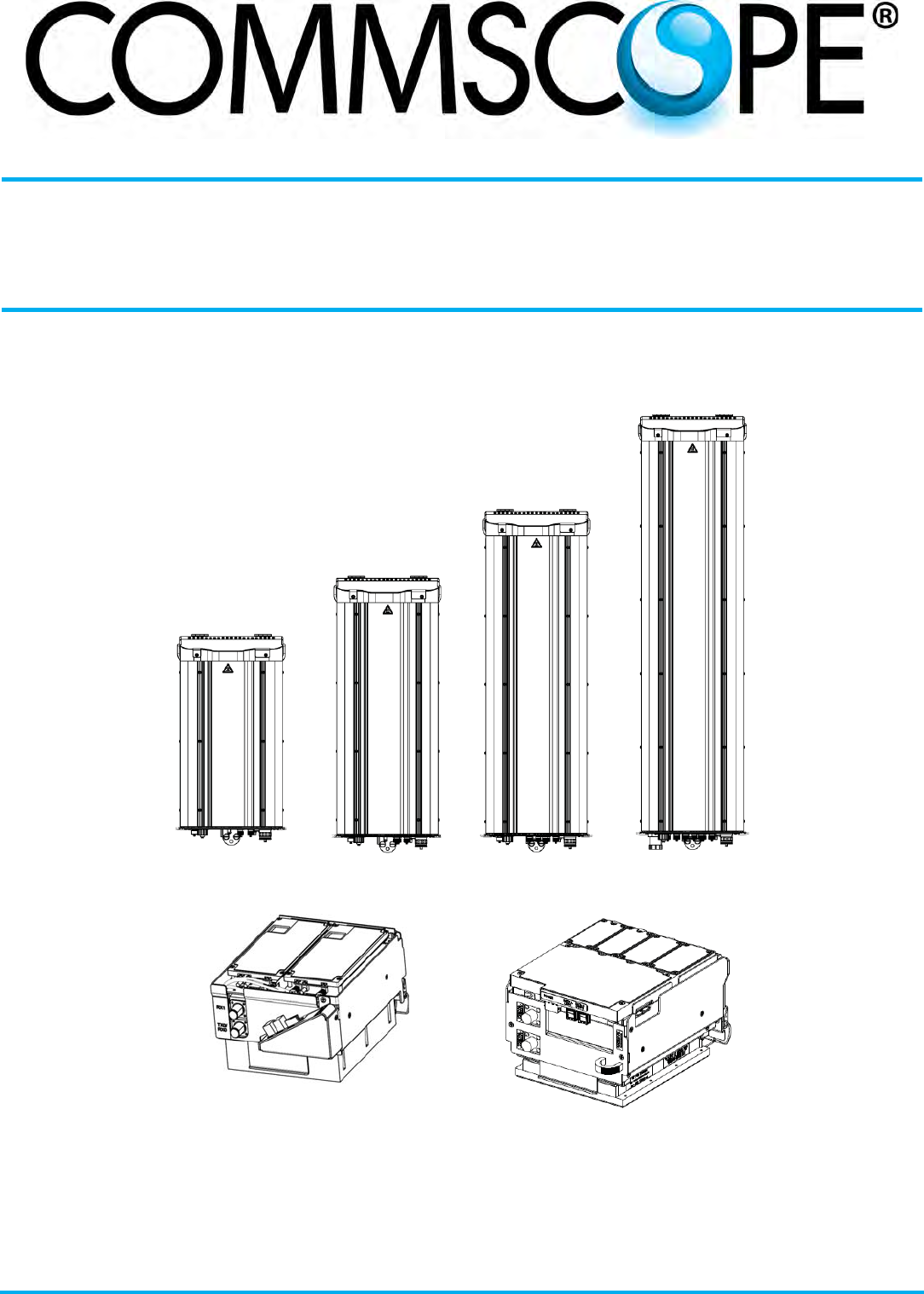
Single-Bay
Prism Remote Unit
Dual-Bay
Prism Remote Unit
Tri-Bay
Prism Remote Unit
Quad-Bay
Prism Remote Unit
Single-Slot RF Module HDM RF Module

DISCLAIMER
ThisdocumenthasbeendevelopedbyCommScope,andisintendedfortheuseofitscustomersandcustomersupportpersonnel.
Theinformationinthisdocumentissubjecttochangewithoutnotice.Whileeveryefforthasbeenmadetoeliminateerrors,
CommScopedisclaimsliabilityforanydifficultiesarisingfromtheinterpretationoftheinformationcontainedherein.The
informationcontainedhereindoesnotclaimtocoveralldetailsorvariationsinequipment,nortoprovideforeverypossible
incidenttobemetinconnectionwithinstallation,operation,ormaintenance.Thisdocumentdescribestheperformanceofthe
productunderthedefinedoperationalconditionsanddoesnotcovertheperformanceunderadverseordisturbedconditions.
Shouldfurtherinformationbedesired,orshouldparticularproblemsarisewhicharenotcoveredsufficientlyforthepurchaser's
purposes,contactCommScope.
CommScopereservestherighttochangeallhardwareandsoftwarecharacteristicswithoutnotice.
COPYRIGHT
©2015CommScope,Inc.AllRightsReserved.Alltrademarksidentifiedby®or™areregisteredtrademarksortrademarks,
respectively,ofCommScope,Inc.
Thisdocumentisprotectedbycopyright.Nopartofthisdocumentmaybereproduced,storedinaretrievalsystem,or
transmitted,inanyformorbyanymeans,electronic,mechanicalphotocopying,recording,orotherwisewithouttheprior
writtenpermissionofCommScope.
OTHER TRADEMARKS
Namesofotherproductsmentionedhereinareusedforidentificationpurposesonlyandmaybetrademarksand/orregistered
trademarksoftheirrespectivecompanies.
REVISION HISTORY
Issue Document Date Technical Updates
1December 2015 Adds support for new RF Modules FWP-W4MT000MOD and FWP-T4MT000MOD-L.
2March 2016 Adds support for HDM TDD RF Module FWP-T4ST000MOD-H. CommScope has acquired TE Connectivity’s
telecom, enterprise and wireless business, which includes the FlexWave Prism product line; CommScope
document FWPP-504-01 replaces TE document TECP-77-265.

FWPP-501-01 Issue 1 • 320000117795 Rev A FlexWave Prism Remote Unit and HDM RF Module Installation Guide
© March 2016 CommScope, Inc. Page iii
TABLE OF CONTENTS
Document Overview ....................................................................................................................................................................... 1
Document Cautions and Notes........................................................................................................................................................... 3
Abbreviations Used in this Guide ....................................................................................................................................................... 4
Overview of Prism Remote Units .................................................................................................................................................... 5
Prism Remote Unit Components ........................................................................................................................................................ 6
Ports and Connectors ......................................................................................................................................................................... 7
Bottom of an AC-Powered Quad-Bay PRU .................................................................................................................................. 8
DC-Powered Quad-Bay PRU ........................................................................................................................................................ 9
Remote Unit Status LED............................................................................................................................................................. 10
SeRF Module LEDs ..................................................................................................................................................................... 11
Overview of RF Modules for Prism Remote Units ...........................................................................................................................12
RF Module Digital/Analog Radio Transceivers.................................................................................................................................. 12
RF Module Types .............................................................................................................................................................................. 14
Single- and Dual-Bay RF Modules with Classic or SuperDARTs ................................................................................................. 15
HDM RF Modules....................................................................................................................................................................... 16
Legacy Dual-Bay 40W RF Modules ............................................................................................................................................ 17
RF Module Components ................................................................................................................................................................... 18
Linear Power Amplifiers ............................................................................................................................................................ 19
Duplexer and Low Noise Amplifier ............................................................................................................................................ 20
Digital Processing Module ......................................................................................................................................................... 20
Cables ........................................................................................................................................................................................ 20
LEDS on Narrowband HDM RF Modules.................................................................................................................................... 21
LEDS on Wideband and Fullband HDM RF Modules.................................................................................................................. 22
Configuring the System with RF .....................................................................................................................................................23
RF Group Assignments for PRU RF Module Bays.............................................................................................................................. 23
Understanding RF Cable Rules.......................................................................................................................................................... 26
RF Module Cables and Supported Bay Use for Single-Card, Dual-Card,
and HDM RF Modules......................................................................................................................................................... 26
RF Module Cables and Supported Bay Installations for Legacy Dual-Bay
40W RF Modules ................................................................................................................................................................ 27
Install the Prism Remote Unit ........................................................................................................................................................29
Planning for a Prism Remote Unit Installation.................................................................................................................................. 29
Safety Precautions ..................................................................................................................................................................... 29
Mounting Plans.......................................................................................................................................................................... 30
Installation Tools and Supplies .................................................................................................................................................. 36
Tools Required for All Mounting Methods ......................................................................................................................... 36
Additional Tools and Supplies Required for Steel-Pole Mounting ..................................................................................... 36
Additional Tools and Supplies Required for Wood-Pole Mounting.................................................................................... 37
Additional Tools and Supplies Required for Flat-Surface Mounting .................................................................................. 37
Tools and Supplies Required to Connect a PRU ................................................................................................................. 38
Unpack and Inspect the Prism Remote Unit and Components ........................................................................................................ 39
Mount the Prism Remote Unit ......................................................................................................................................................... 42
Mounting Cautions .................................................................................................................................................................... 42
Mounting Methods.................................................................................................................................................................... 42

FlexWave Prism Remote Unit and HDM RF Module Installation Guide 320000117795 Rev A • FWPP-501-01 Issue 1
Page iv © March 2016 CommScope, Inc.
Table of Contents
Steel Pole Installation Using Steel Banding ........................................................................................................................ 43
Pole Mount Installation Using Bolts ................................................................................................................................... 46
Wood-Framed Wall Mounting Procedure .......................................................................................................................... 47
Masonry Wall Mounting..................................................................................................................................................... 49
Installing a PRU on the Mounting Bracket.......................................................................................................................... 51
Ground the PRU Chassis ................................................................................................................................................................... 52
Connect a Network Cable to the PRU Chassis .................................................................................................................................. 53
Connect Fiber Cable to the PRU Chassis........................................................................................................................................... 55
Option A: Hardened Multi-Fiber Optic Connector .................................................................................................................... 55
Option B: Fiber Pass-Through Connector .................................................................................................................................. 61
Option C: ProAx Connector (Legacy AC-Powered PRUs) ........................................................................................................... 65
Connect the Antenna Cable.............................................................................................................................................................. 69
Connect the Power Wiring................................................................................................................................................................ 70
Option 1: Connect the AC Power Wiring ................................................................................................................................... 70
Option 2: Connect the DC Power Wiring ................................................................................................................................... 73
Determine the Circuit Breaker or Fuse for the PRU.......................................................................................................................... 76
Power Consumption .................................................................................................................................................................. 76
Power Consumption Tables....................................................................................................................................................... 76
(Optional) Connect the Prism Remote Unit to a UPS ....................................................................................................................... 78
Install the RF Module(s) .................................................................................................................................................................80
Safety Precautions ............................................................................................................................................................................ 80
Guard against Damage from Electro-Static Discharge...................................................................................................................... 81
Unpack and Inspect the RF Module.................................................................................................................................................. 81
Remove Release Liners from the RF Module.................................................................................................................................... 82
Check the DC Power Switch for the Module Bay.............................................................................................................................. 84
Dual-Bay Modules Only—Remove the Module Bay Shelf ................................................................................................................ 85
Install the RF Module into the Prism Remote Chassis ...................................................................................................................... 86
Secure RF Module Latches................................................................................................................................................................ 94
Connect Latches on Single-Bay and HDM RF Modules.............................................................................................................. 94
Connect Latches on Dual-Bay RF Modules ................................................................................................................................ 95
Latches on Legacy Dual-Bay 40W RF Modules .......................................................................................................................... 96
Verify that the RF Module Mounting Hook is Engaged ............................................................................................................. 96
Connect the RF Module Cables to the PRU Chassis.......................................................................................................................... 97
Connecting Cables in a Single-Bay RF Module Installation........................................................................................................ 97
Connecting Cables in a Dual-Bay RF Module Installation ........................................................................................................ 100
Power on the RF Module(s) and the Prism Remote Unit................................................................................................................ 105
Close the Remote Unit Door and Solar Shield ................................................................................................................................ 107
Provision the Prism Remote Unit.................................................................................................................................................... 108
FlexWave Notch Filter (FWP-SPRINTFILTER) .................................................................................................................................108

FWPP-501-01 Issue 1 • 320000117795 Rev A FlexWave Prism Remote Unit and HDM RF Module Installation Guide
© March 2016 CommScope, Inc. Page v
Table of Contents
Fan Module Maintenance ............................................................................................................................................................112
Annual Fan Checkup ....................................................................................................................................................................... 112
Potential Fan Alarms....................................................................................................................................................................... 112
Replacing the Fan Module .............................................................................................................................................................. 112
Specifications...............................................................................................................................................................................115
Standards Certification ................................................................................................................................................................117
DCCS Global Technical Support ....................................................................................................................................................119
Helpline Support ...................................................................................................................................................................119
Online Access ........................................................................................................................................................................119
Email.....................................................................................................................................................................................119
Return Material Authorizations ...................................................................................................................................................... 119
Technical Training ........................................................................................................................................................................... 120
Accessing FlexWave Prism User Documentation............................................................................................................................ 120

FlexWave Prism Remote Unit and HDM RF Module Installation Guide 320000117795 Rev A • FWPP-501-01 Issue 1
Page vi © March 2016 CommScope, Inc.
Table of Contents

FWPP-501-01 Issue 1 • 320000117795 Rev A FlexWave Prism Remote Unit and HDM RF Module Installation Guide
© March 2016 CommScope, Inc. Page 1
DOCUMENT OVERVIEW
ThisdocumentprovidestheinformationyouneedtoinstallaCommScopeFlexWave®PrismRemote
Unit(PRU).InstallationinstructionsarealsoprovidedforthefollowingPrismRemoteUnitRFModules
thatresideinaPRU:
•Single-BayRFModules,whichincludestheHDMandTDDRFModules
•Dual-BayRFModules,whichincludestheDual-BandRFModulesandLegacy40WRFModules.
NOTE: RF Modules can be ordered separately or may come pre-installed in a Prism Remote Unit.
Table1liststhePrismRemoteUnitchassisandTable2throughTable8onpage3listthePrismRF
Modulesthatthisinstallationguidesupports.
Table 1. Supported FlexWave Prism Remote Unit Chassis
Catalog Number Description
FP1-XXXXXXXXXXXRU Single-Bay Prism Remote
FP2-XXXXXXXXXXXRU Dual-Bay Prism Remote
FP3-XXXXXXXXXXXRU Tri-Bay Prism Remote
FP4-XXXXXXXXXXXRU Quad-Bay Prism Remote
Table 2. Supported High-Density Module (HDM), Single Bay RF Modules
Catalog Number Description
FWP-L4MT000MOD 20W 700 LABC Module, MIMO
FWP-L4MTU4MMOD 20W 700 LABC/700uC, Dual, Non-Diversity
FWP-U4MT000MOD 20W 700 uC Module, MIMO
FWP-44MT000MOD 20W 800 MIMO, with two External Filters
FWP-441T841MOD 20W 800 SMR/ 1900 PCS, Dual with 800 External Filter
FWP-C4MT000MOD 20W 850 Cell/1900 PCS, Dual, Non-Diversity
FWP-B4MT000MOD 20W 850 MIMO
FWP-B410000MOD 20W 850 Wideband Cell, Non-Diversity
FWP-B810100MOD 40W 850 Wideband Cell, Non-Diversity
FWP-84MT000MOD 20W 1900 PCS MIMO, Non-Diversity
FWP-84MTA4MMOD 20W 1900/2100 Dual
FWP-W4MT000MOD 20W 2300 WCS FDD, MIMO
FWP-T4MT000MOD-L 20W 2500 TDD Low, MIMO
FWP-T4ST000MOD-H 20W 2500 TDD High, SISO, 2615-2690
FWP-A4MT000MOD 20W AWS MIMO, Non-Diversity
FWP-A416000MOD 20W AWS, Non-Diversity
FWP-A81T000MOD 40W AWS SISO, Non-Diversity
FWP-8416000MOD 20W PCS, Non-Diversity
FWP-881T000MOD 40W PCS SISO, Non-Diversity

FlexWave Prism Remote Unit and HDM RF Module Installation Guide 320000117795 Rev A • FWPP-501-01 Issue 1
Page 2 © March 2016 CommScope, Inc.
Document Overview
Table 3. Supported Single SuperDART, Single Bay RF Modules
Catalog Number Description
FWP-I210000MOD 6.5W 800 APAC, Non-Diversity, Classic (Extended 1 MHz)
FWP-6216000MOD 10W 900 EGSM, Non-Diversity
FWP-K216000MOD 10W 900 P-GSM, Non-Diversity
FWP-F216000MOD 10W APAC EGSM, Non-Diversity
FWP-7416000MOD 20W 1800 GSM, Non-Diversity
FWP-9416D00MOD 20W 2100 UMTS Module, DIV Ready
FWP-9416000MOD 20W 2100 UMTS, Non-Diversity
FWP-L416000MOD 20W 700 Lower ABC Module, Non-Diversity
FWP-U416000MOD 20W 700 LTE, UPPER C, SISO, Non-Diversity
FWP-U816100MOD 40W 700 Upper C, Non-Diversity
Table 4. Supported Dual SuperDART, Single Bay, Non-Diversity RF Modules
Catalog Number Description
FWP-741S000MOD 20W GSM 1800
FWP-841S000MOD 20W PCS 1900 12S
FWP-A41S000MOD 20W AWS 2100
FWP-941S000MOD 20W UMTS 2100
Table 5. Supported Single SuperDARTs, Diversity, Single Bay RF Modules
Catalog Number Description
FWP-6226000MOD 10W 900 EGSM
FWP-K226000MOD 10W 900 P-GSM
FWP-7426000MOD 20W 1800 GSM
FWP-9426000MOD 20W 2100 UMTS
FWP-A426000MOD 20W AWS
FWP-8426000MOD 20W PCS
Table 6. Supported Classic DART, Single Bay RF Modules
Catalog Number Description
FWP-4210000MOD 6.5W 800 SMR Module, Non-Diversity
FWP-J410D00MOD 20W 850 Cell (870-890), Diversity Ready
FWP-8420000MOD 20W 1900 PCS Diversity
FWP-8410000MOD 20W 1900 PCS Non-Diversity
FWP-A420000MOD 20W 2100 AWS Diversity
FWP-A410000MOD 20W 2100 AWS Non-Diversity
FWP-B420000MOD 20W Wideband Cell, Diversity

FWPP-501-01 Issue 1 • 320000117795 Rev A FlexWave Prism Remote Unit and HDM RF Module Installation Guide
© March 2016 CommScope, Inc. Page 3
Document Overview
DOCUMENT CAUTIONS AND NOTES
Twotypesofmessages,identifiedbelow,appearinthetext:
CAUTION! Cautions indicate operations or steps that could cause personal injury, induce a safety
problem in a managed device, destroy or corrupt information, or interrupt or stop services.
NOTE: Notes contain information about special circumstances.
Table 7. Supported Classic DART, Two Bay RF Modules
Catalog Number Description
FWP-8810000MOD 40W PCS, Non-Diversity
FWP-A810000MOD 40W AWS, Non-Diversity
Table 8. Supported Dual Classic DART, Two Bay RF Modules
Catalog Number Description
FWP-D210000MOD 6.5W 800/900 ESMR, Non-Diversity

FlexWave Prism Remote Unit and HDM RF Module Installation Guide 320000117795 Rev A • FWPP-501-01 Issue 1
Page 4 © March 2016 CommScope, Inc.
Document Overview
ABBREVIATIONS USED IN THIS GUIDE
AC Alternating Current MMeter
AMP Amperes Mbps Megabits Per Second
AUX Auxiliary MDI Medium Dependent Interface
AWG American Wire Gauge MHz Megahertz
CCentigrade MIMO Multiple-Input Multiple-Output
CAT Category MM Millimeter
CDRH Center for Diseases and Radiological Health MOD Module
cm Centimeter MPE Maximum Permissible Exposure
DART Digital/Analog Radio Transceiver NC Normally Closed
dB Decibel NO Normally Open
dBm Decibel-milliwatts NOC Network Operations Center
DC Direct Current OSP Outside Plant
DCS Distributed Call Signaling PA Power Amplifier
DD Digital Dividend PA Power Amplifier
DIV Diversity PRIM Primary
DPA Dynamic Phase Alignment PRU Prism Remote Unit
DPM Digital Processing Module PWR Power
EMC Electromagnetic Compatibility REV Reverse
ESD Electro-Static Discharge RF Radio Frequency
EU European Union Rx Receive
FFahrenheit SDART Super Digital/Analog Radio Transceiver
FCC Federal Communications Commission SeRF Serialized RF
FDA Food and Drug Administration SFP Small Form-Factor Pluggable
FRU Fullband Remote Unit SYNTH Synthesizer
FWD Forward TDD Time-Division Duplex
HDM High Density Module TIM Thermal-Interface Material
HMFOC Hardened Multi-Fiber Optic Connector Tx Transmit
Hz Hertz UL Underwriters' Laboratories, Inc.
IC Industry Canada UMTS Universal Mobile Telecommunications System
IP Internet Protocol UPS Uninterrupted Power Supply
LAN Local Area Network VAC Volts, Alternating Current
LC Lead Covered WWatt
LED Light-Emitting Diode WCS Wireless Communications Services
LVDS Low-Voltage Differential Signaling WDM Wavelength Division Multiplexer

FWPP-501-01 Issue 1 • 320000117795 Rev A FlexWave Prism Remote Unit and HDM RF Module Installation Guide
© March 2016 CommScope, Inc. Page 5
Overview of Prism Remote Units
OVERVIEW OF PRISM REMOTE UNITS
FlexWavePRUscontrolRFemissions,interfacewiththeFlexWavePrismHostUnitIIandperformthe
opticaltoelectricalconversionfortransporttotheantennas.ThePRUisanenvironmentally-sealedunit
designedforoutdoorusethathousestheelectronicassembliessuchastheDigital/AnalogRadio
Transceiver(DART)boardandthePowerAmplifier,andsealsoutdirtandmoisture.ThePRUusesfans
locatedonthetopofeachunittocoolitschassis.Theantennacableconnectors,fiberconnectors,ACor
DCpowerconnector,andtheunitstatusindicatorarelocatedonthebottomoftheunit.
APRUsupportsorprovidesthefollowingbasicfunctions:
•ReceivesontheforwardpaththedigitizedspectrumfromtheHostandconvertsthespectrumback
intoanRFsignaltobedistributedviaanexternallymountedantennasystem.Onthereversepath,
thePRUdigitizesthedesignatedRFspectrumanddigitallytransportsitoversinglemodefiberor
MillimeterWave(MMW)totheHost.
•ProvidesRFinterface(antennaport)fortheantennas.
•AcceptseitherACorDCpowerinput.
FlexWave Prism Remote Unit and HDM RF Module Installation Guide 320000117795 Rev A • FWPP-501-01 Issue 1
Page 6 © March 2016 CommScope, Inc.
Overview of Prism Remote Units
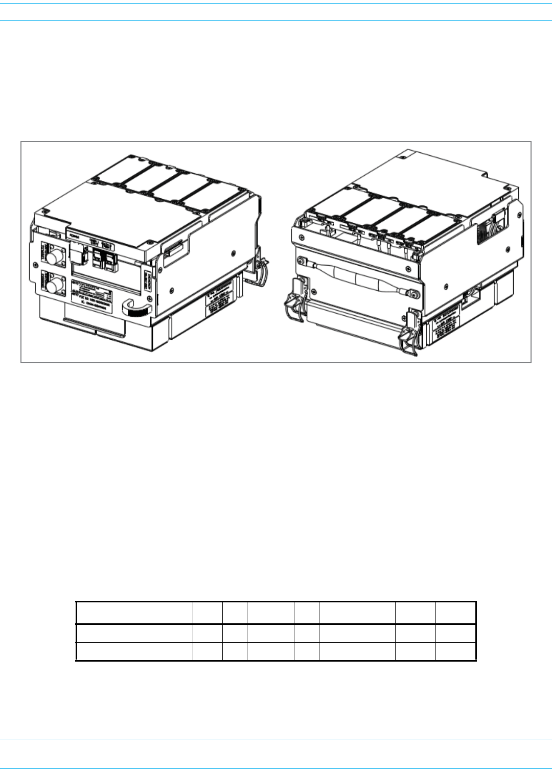
PRISM REMOTE UNIT COMPONENTS
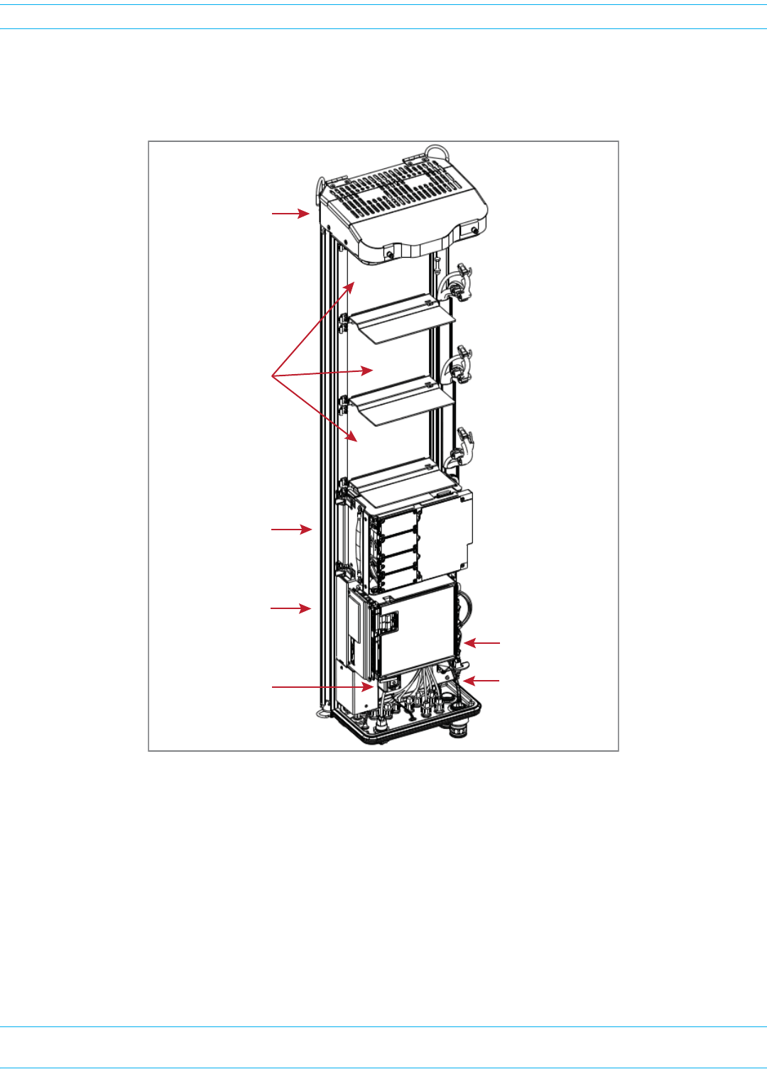
Figure1showsthemaincomponentsofthePRUanditscorrespondingRFModules.
Figure 1. Prism Remote Unit Components
SeRF Module
Main AC/DC Power
switch for the chassis
HDM RF Module
DC Power switches
for RF Modules
Fan Module
Cable connectors
RF Module slots

FWPP-501-01 Issue 1 • 320000117795 Rev A FlexWave Prism Remote Unit and HDM RF Module Installation Guide
© March 2016 CommScope, Inc. Page 7
Overview of Prism Remote Units
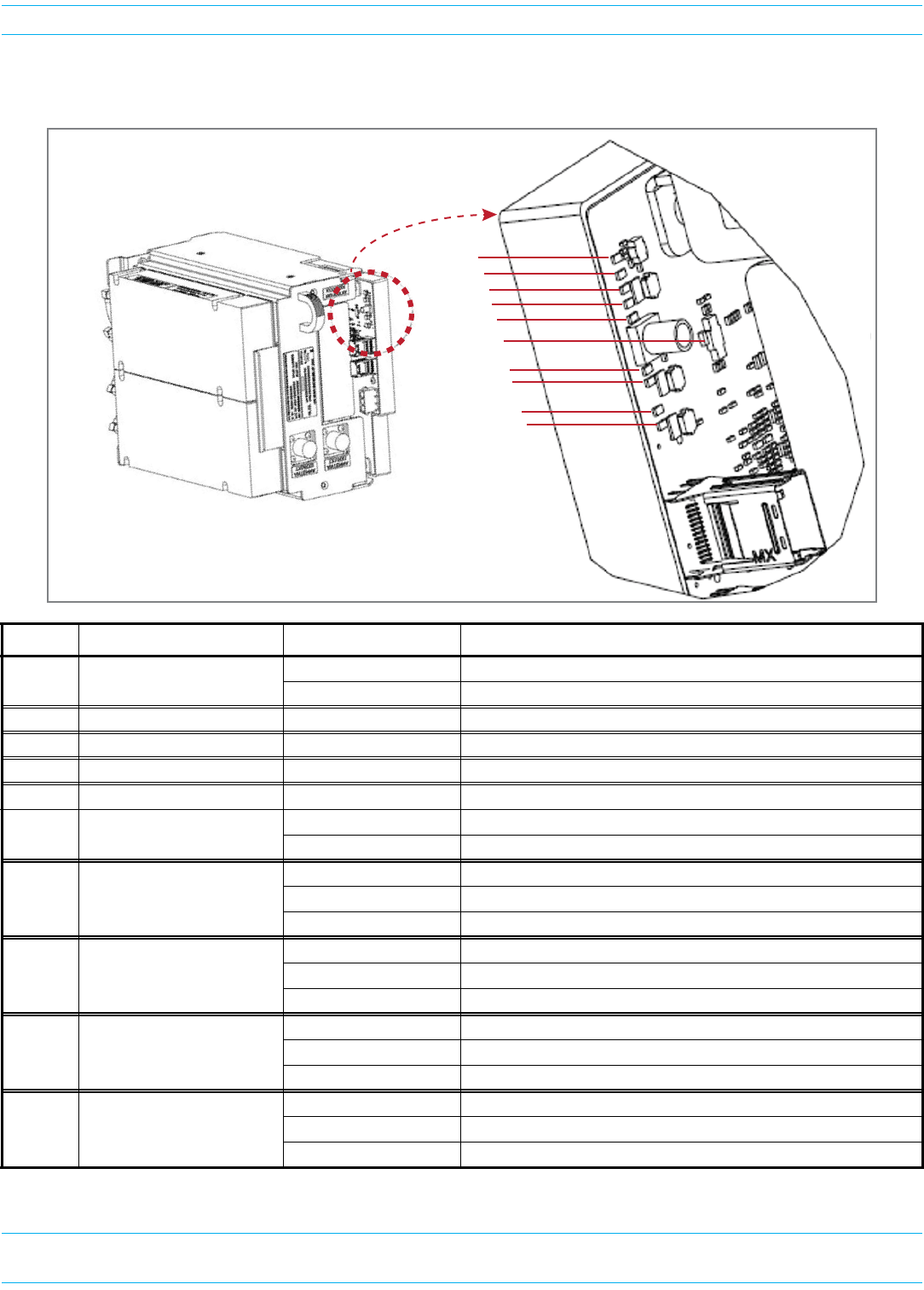
PORTS AND CONNECTORS
MakesureyourefertothesectionthatdescribesthePRUdeployedinyourinstallation."Bottomofan
AC-PoweredQuad-BayPRU”onpage8and"DC-PoweredQuad-BayPRU”onpage9showsthe
differencesbetweenanAC-poweredandaDC-poweredPRU.Thedifferenceswillbethesamefor
Single-Bay,Dual-Bay,andTri-Baychassis.Additionally,forboththeAC-PoweredandDC-Powered
PRUs:
•ThenumberofAntennaconnectorsonthebottomofaPRUcorrespondstothenumberofRFModule
baysinthatPRUmodel,wheretherearetwoAntennaconnectorsperbay.Forexample:
–TherearefourRFModulebaysinaQuad-BayPRU,sothereareeightAntennaconnectors.
–ThereisoneRFModulebayintheSingle-BayPRU,sotherearetwoAntennaconnectors.
•TheSingle-BayPRUonlyhasoneFiberconnectorwhereastheotherthreePRUmodelshavetwo.
FlexWave Prism Remote Unit and HDM RF Module Installation Guide 320000117795 Rev A • FWPP-501-01 Issue 1
Page 8 © March 2016 CommScope, Inc.
Overview of Prism Remote Units
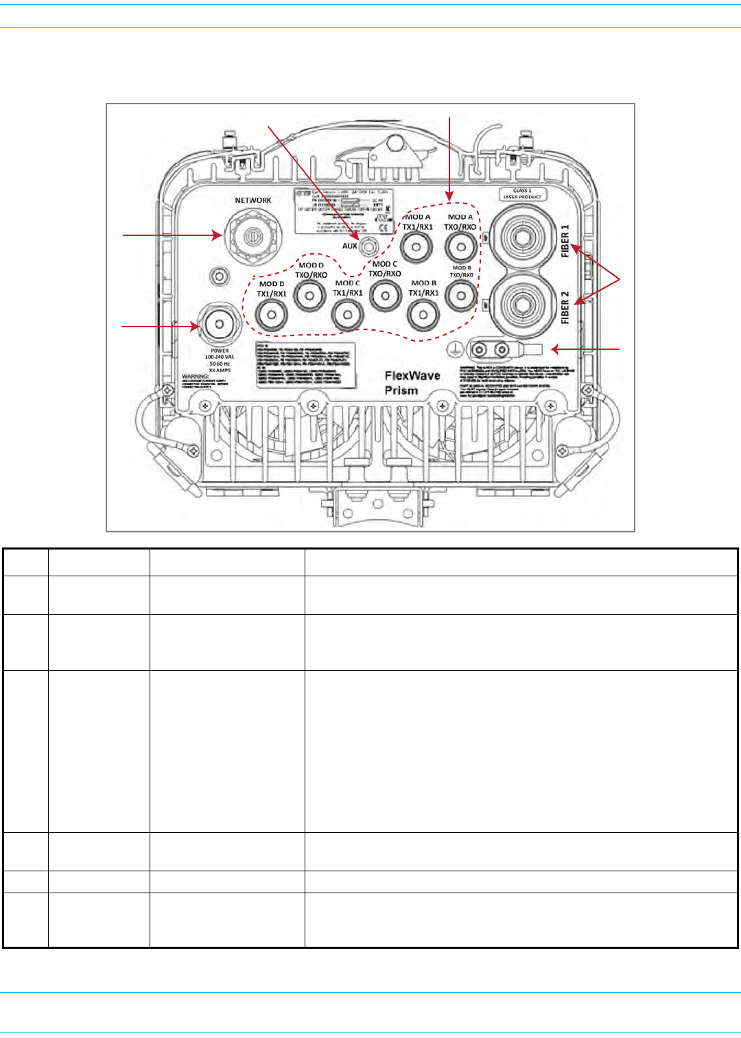
Bottom of an AC-Powered Quad-Bay PRU
Ref # Component Device Function
1AUX connector Four contact closure
inputs
Connection points for two external alarm inputs.
2Antenna
connectors
Eight Input/Output
Impedance 50Ω N-Type
connectors (female)
Connection points between the PRU and antennas that are labeled MOD X
TXO/RXO or MOD X TX1/RX1(where the first X can be A, B, C, or D). For
further information, see "Understanding RF Cable Rules” on page 26.
3Fiber
connectors
One of the following:
• Hardened Multi-Fiber
Optic Connector
(shown)
• Fiber Pass-Through
• ProAx connectors that
provide four BX5
connectors (Legacy
PRUs)
Connection points between the PRU and the Outside Plant (OSP) box. The
Single-BAY PRU only has the Fiber 1 connector. For further information on
the three Fiber connector types, see "Connect Fiber Cable to the PRU
Chassis” on page 55.
4Dual-Ground
connector
Ground connector Grounds the PRU.
5AC Power port Sealed 3-pin port Connection point between the PRU and an AC power junction box.
6Network
Connector port
RJ-45 female connector LAN Extension of the Host Unit Network that provides access to the Prism
Network for access and monitoring via an up to a 100 Mbps IP back-haul
connection to remote devices.
2
5
1
3
4
6
FWPP-501-01 Issue 1 • 320000117795 Rev A FlexWave Prism Remote Unit and HDM RF Module Installation Guide
© March 2016 CommScope, Inc. Page 9
Overview of Prism Remote Units
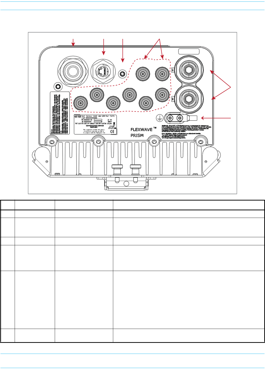
DC-Powered Quad-Bay PRU
Ref # Component Device Function
1DC Power port Pass-through gland Connection point between the PRU and a -40 to -60 Vdc power source.
2Network
Connector port
RJ-45 female connector LAN Extension of the Host Unit Network that provides access to the Prism
Network for access and monitoring via an up to a 100 Mbps IP back-haul
connection to remote devices.
3AUX connector Four contact closure inputs Connection points for two external alarm inputs.
4Antenna
connectors
Eight Input/Output
Impedance 50Ω N-Type
connectors (female)
Connection points between the PRU and up to eight antennas that are
labeled MOD X TXO/RXO or MOD X TX1/RX1(where the first X can be A, B,
C, or D). For further information, see "Understanding RF Cable Rules” on
page 26.
5Fiber connectors One of the following:
• Hardened Multi-Fiber
Optic Connector
(shown)
• Fiber Pass-Through
• ProAx connectors that
provide four BX5
connectors (Legacy
PRUs)
Connection points between the PRU and the Outside Plant (OSP) box. For
further information on the three Fiber connector types, see "Connect Fiber
Cable to the PRU Chassis” on page 55.
6Dual-Ground
connector
Ground connector Grounds the PRU.
POWER
48vdc/XXA
NETWORK
AUX
MOD A
TX1/RX1
MOD A
TXO/RXO
MOD B
TX1/RX1
MOD B
TXO/RXO
MOD C
TX1/RX1
MOD C
TXO/RXO
MOD D
TX1/RX1
MOD D
TXO/RXO
FIBER 1FIBER 2
123 4
5
6
CLASS 1
LASER PRODUCT
FlexWave Prism Remote Unit and HDM RF Module Installation Guide 320000117795 Rev A • FWPP-501-01 Issue 1
Page 10 © March 2016 CommScope, Inc.
Overview of Prism Remote Units
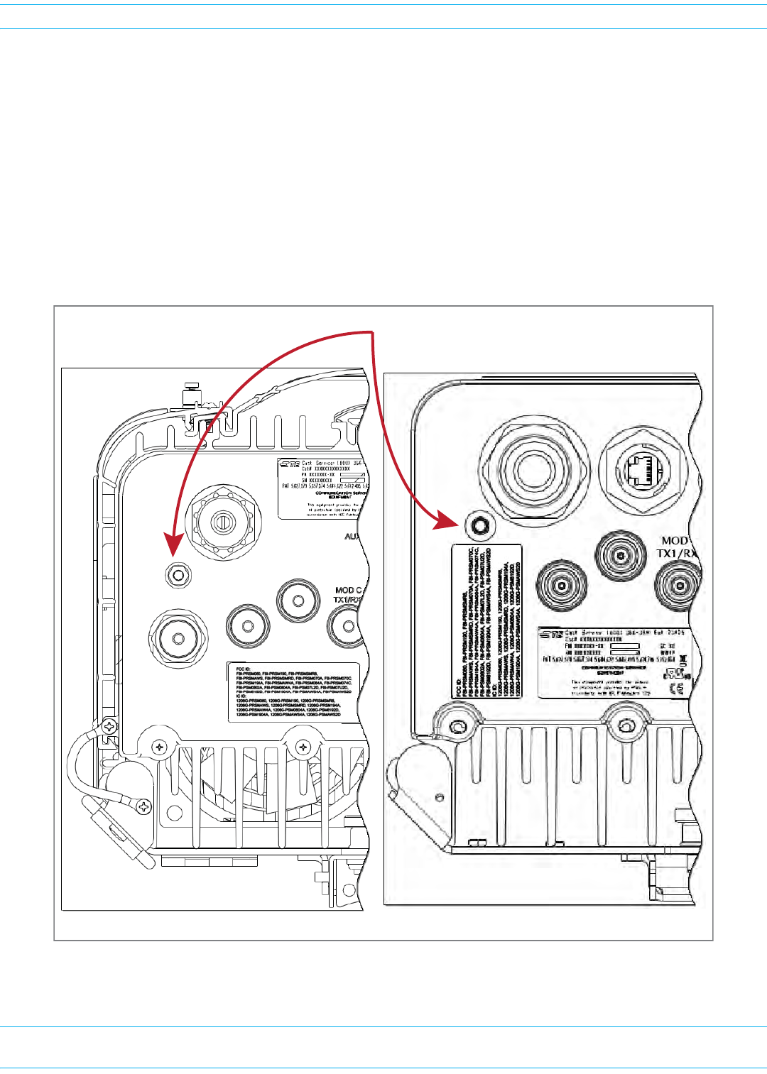
Remote Unit Status LED
ThissectionillustratestheStatusLEDonaQuad-BayPRU.TheStatusLEDfortheSingle-Bay,Dual-Bay,
andTri-BayPRUsisinthesamelocationandfunctionsthesameastheStatusLEDfortheQuad-Bay
PRU.
TheRemoteUnithasasingleredStatusLEDthatislocatedonthebottomofthechassis.Atsystem
startup,theStatusLEDisredtoindicatethattheRemoteUnitispoweringupandthattheSeRF
processordoesnotyetcontroltheRemoteUnit;theStatusLEDwillremainredforapproximatelyone
minute.IfafterthreeminutestheStatusLEDisstillred,itindicatestheRemoteUnitisunabletoboot
up.(SomecommonfailuresthatcanpreventthePRUfrombootingupincludeafaultyPowerSupply,
SeRF,orCompactFlashCard.)
BoƩom of an AC-Powered PRU BoƩom of a DC-Powered PRU
Status LED
NETWORK
POWER
48VDC/XXA
MOD D
TX1/RX1
NETWORK
MOD D
TX1/RX1
POWER
100-240 VAC
50-60 Hz
XX AMPS
WARNING:
HIGH LEAKAGE CURRENT. EARTH
CONNECTION ESSENTIAL BEFORE
CONNECTING SUPPLY
MOD D
TX0/RX0
MOD D
TX0/RX0
FWPP-501-01 Issue 1 • 320000117795 Rev A FlexWave Prism Remote Unit and HDM RF Module Installation Guide
© March 2016 CommScope, Inc. Page 11
Overview of Prism Remote Units
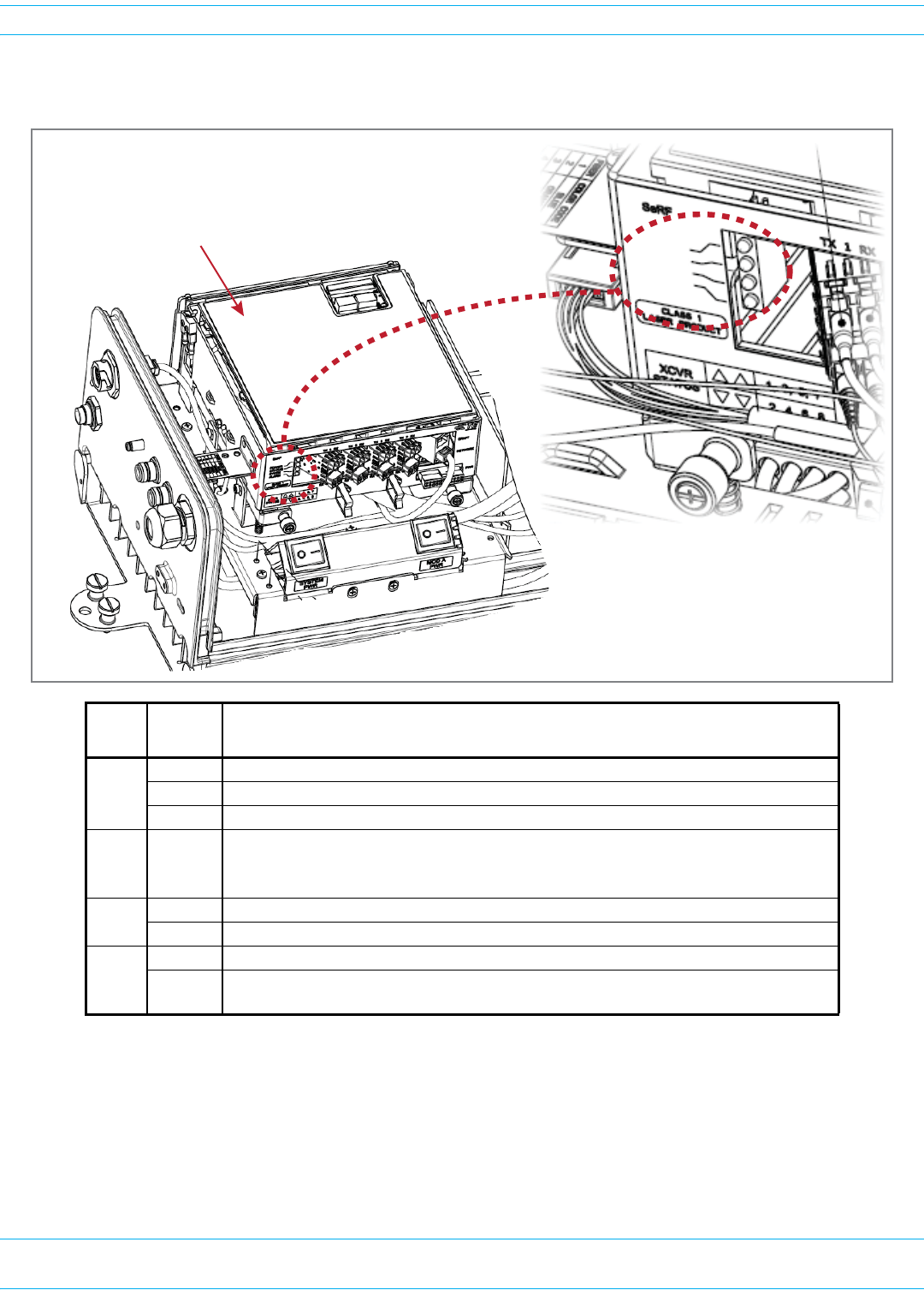
SeRF Module LEDs
NOTE: The SeRF Module LEDs automatically enter a LED Roll Test sequence (cycle through its colors)
when the SeRF FPGA is loaded (approximately 4 minutes after initial power up) or when a
SeRF synthesizer failure occurs. The LED Roll Test sequence takes approximately two seconds
to complete, and cycles the ALARM, SYNTH, and STATUS LEDs, after which the LEDs begin
normal operation. Additionally, an active SeRF Synthesizer failure causes the same LED
sequencing approximately every minute until the SeRF failure clears.
LED LED
Color
Description
POWE
R
• GREEN • Power OK and operating properly
•RED • Power supply out of tolerance
•OFF •No power present
STATU
S
•GREEN
•R
ED
• No alarm for the SeRF II Module
• Initial bootup sequence and should become GREEN within 1 minute;
if RED after bootup, a Major alarm exists for the SeRF Module
SYNTH •GREEN •Locked
•RED • Unlocked or is in initial bootup sequence
ALAR
M
• GREEN • No major alarm is present in the PRU or in any downstream unit
• RED • Initial bootup sequence, or a major alarm is present in the PRU or in any downstream
unit
SeRF Module
POWER
STATUS
SYNTH
ALARM

FlexWave Prism Remote Unit and HDM RF Module Installation Guide 320000117795 Rev A • FWPP-501-01 Issue 1
Page 12 © March 2016 CommScope, Inc.
Overview of RF Modules for Prism Remote Units
OVERVIEW OF RF MODULES FOR PRISM REMOTE UNITS
DependentonthePrismRemoteUnitmodel,aPRUenclosurecanhavefromonetofourRFModulebays
andcansupportuptofourRFModules,asindicatedbythemodelname.Thatis,theSingle-BayPRUhas
oneRFModulebayandcanonlysupportoneRFModule,andtheQuad-BayPRUhasfourRFModule
baysandcansupportuptofourRFModules.
ThefunctionoftheRemoteUnitRFModulesontheForwardPathisto:
•convertthedigitizedRFtransportedfromtheHosttoAnalogRF
•amplifytheAnalogRFsignal
•providesignalfiltering.
ThefunctionoftheRemoteUnitRFModulesontheReversePathisto:
•converttheAnalogRFfromthehandsettoDigitalRFfortransporttotheHost
•amplifytheDigitalRFsignal
•providesignalfiltering.
NOTE: The RF Modules are field replaceable, but cannot be serviced in the field.
RF MODULE DIGITAL/ANALOG RADIO TRANSCEIVERS
EachRFModulecansupportanyofthefollowingDigital/AnalogRadioTransceiver(DART)
combinations:
•oneClassicDARToroneSingleSuperDART
•twoClassicDARTs(i.e.,the6.5W800/900ESMRModule,Non-Diversity,Classic)
•twoClassicDARTs—Diversity
•twoSingleSuperDARTs—Diversity
•oneDualSuperDART
•oneortwosetsofTxandRxBoards(HDM).
EachRFModulewillhaveuptotwo6-timeslotDARTsorone12-timeslotDARTperRFModule.
TheDARTtypedeterminesthemaximumnumberoflinks,wheretherecanbeuptoeightClassicDARTs
orSingleSuperDARTsthatsupport39MHzeach,orupto4DualSuperDARTsthatsupportupto75MHz
each.
FWPP-501-01 Issue 1 • 320000117795 Rev A FlexWave Prism Remote Unit and HDM RF Module Installation Guide
© March 2016 CommScope, Inc. Page 13
Overview of RF Modules for Prism Remote Units
PrismsupportstheDARTModuletypeslistedbelow.
•ClassicDARTsare6-timeslotDARTsthatsupportupto35MHzcontiguousbandwidth(seeTable9).
•SingleSuperDARTsare6-timeslotDARTsthatsupporttwonon-contiguousbandsintheentire
frequencyrangeoftheDART,butcannotexceed39MHztotalRFbandwidth(seeTable10).
•DualSuperDARTsare12-timeslotDARTsthatsupportupto60-75MHz(seeTable11onpage14)
NOTE: Industry Canada PCS 20 dB nominal bandwidth is less than 61.5 MHz.
NOTE: Industry Canada AWS 20 dB nominal bandwidth is less than 47.2 MHz
Table 9. Single-Position Classic DARTs
DART Module Type Maximum
Bandwidth (MHz)
Maximum
Fiber Slots
800 APAC iDEN Classic 19 3
800 SMR Classic 7* 3
850 Cell Classic 25 4
900 SMR Classic 51
* Classic Prism RF Modules and Spectrum RAU support 18 MHz; Prism HDM 800
only supports 7 MHz, per Sprint direction.
Table 10. Single-Position SuperDARTs(1)
DART Name Used in… Maximum
Frequency
Span (MHz)
Maximum
Bandwidth
(MHz)
Maximum
Fiber
Slots
Host Units HEUs
700 IABC SGL SuperDART Yes Yes 18 18 3
700 uC SGL SuperDART Yes Yes 10 10 2
900 EGSM SGL SuperDART Yes No 35 35 6
1800 GSM SGL SuperDART Yes No 75 39 6
1900 PCS SGL SuperDART Yes Yes 70 39 6
2100 AWS SGL SuperDART Yes Yes 45 39 6
2100 UMTS SGL SuperDART Yes No 60 39 6
2300 WCS FDD, MIMO Yes No 10 10 2
2500 TDD Low, MIMO
2500 TDD High, SISO YesNo757512
(1) When using a Host Unit with both a SeRF II and System Board II or III, the bandwidths and fiber for the following Single
SuperDARTs can be greater than 6 fiber slots, for full-band capability, when used in Host Unit Slots 1 and 3: 1800 GSM SGL
SuperDART; 1900 PCS SGL SuperDART; 2100 AWS SGL SuperDART; 2100 UMTS SGL SuperDART.
This requires 12 fiber slots when full-band passband is selected for these Single SuperDARTs in Host Unit DART positions 1
and 3.

FlexWave Prism Remote Unit and HDM RF Module Installation Guide 320000117795 Rev A • FWPP-501-01 Issue 1
Page 14 © March 2016 CommScope, Inc.
Overview of RF Modules for Prism Remote Units
RF MODULE TYPES
TheRemoteUnitRFModulesareavailableinthefollowingformats,andasdescribedinthefollowing
sections:
•"Single-andDual-BayRFModuleswithClassicorSuperDARTs”onpage15
•"HDMRFModules”onpage16
•"LegacyDual-Bay40WRFModules”onpage17.
Table 11. Dual-Position SuperDARTs
DART Module Type Maximum
Bandwidth
(MHz)
Maximum
Fiber
Slots
1800 GSM DL SuperDART 75 12
1900 PCS DL SuperDART 70 12
2100 AWS DL SuperDART 45 8
2100 UMTS DL SuperDART 60 12
FWPP-501-01 Issue 1 • 320000117795 Rev A FlexWave Prism Remote Unit and HDM RF Module Installation Guide
© March 2016 CommScope, Inc. Page 15
Overview of RF Modules for Prism Remote Units
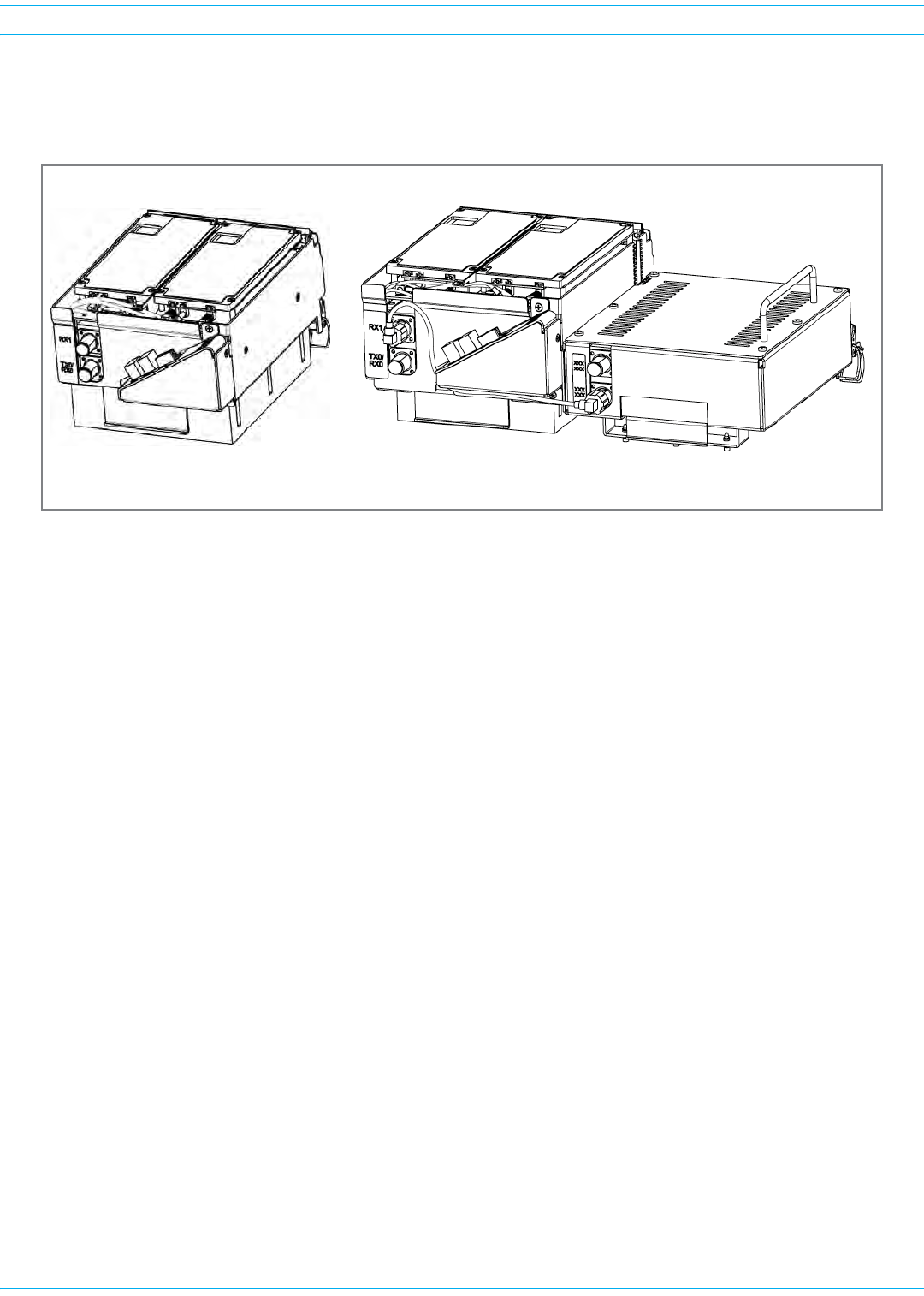
Single- and Dual-Bay RF Modules with Classic or SuperDARTs
Figure2showsexamplesofSingle-andDual-BayRFModules,bothofwhichhavetwoDARTs.
Figure 2. Single- and Dual-Bay RF Modules
Single-BayRFModuleshavethefollowingelements:
•oneortwoDARTs
•oneDuplexerthatcomprises
–oneLowNoiseAmplifier(LNA)
–onePowerDetector(PD)
•oneLinearPowerAmplifier(LPA)
•oneRemoteDARTInterface(RDI)board.
Dual-BandDual-BayRFModuleshavethefollowingelements:
•twoDARTs
•twoDuplexers,eachofwhichcomprises
–oneLowNoiseAmplifier(LNA)
–onePowerDetector(PD)
•oneLinearPowerAmplifier(LPA)
•oneRemoteDARTInterface(RDI)board.
Dual-Band Dual-Bay RF ModuleSingle-Bay Dual-Card RF Module
NOTE: Some Single-Bay RF Modules
have only 1 DART Card.
FlexWave Prism Remote Unit and HDM RF Module Installation Guide 320000117795 Rev A • FWPP-501-01 Issue 1
Page 16 © March 2016 CommScope, Inc.
Overview of RF Modules for Prism Remote Units
HDM RF Modules
High-DensityModule(HDM)RFModules(Figure3)aredesignedtoprovidetheabilitytodeployeither
atwo20WMultipleInputMultipleOutput(MIMO)pathsofthesameband,knownasaMIMORF
Module;two20WSingleInputSingleOutput(SISO)withtwodifferentbands,knownasdualRFModule;
orasingle40WSingleInputSingleOutput(SISO)RFModulewithinasingle-bayofaPRU.
Figure 3. HDM RF Modules
AnHDMRFModuledoesthefollowing:
•interfaceswithoneHostDART-eitherClassicorSuperDART,oroneCDIU
•supportstwonon-contiguousRFslicesupto35MHztotalbandwidthinaDualorMIMO
configuration
•supportsfullbandwidthinaSISOconfiguration,upto75MHz
•supports20Wperband/PathinaDual/MIMORFModule
•supportsupto40WRFoutputpowerinaSISORFModule.
ThecomponentsofaPRUHDMRFModulearedependentonthemoduletype,aslistedinTable12.
Table 12. Components of PRU HDM RF Modules
RF Module Type DPM LPA Duplexer LNA Power Detector Rx Card Tx Card
SISO 11 1 1 1 1 1
MIMO/Dual Band Module 12 2 2 2 2 2
FWPP-501-01 Issue 1 • 320000117795 Rev A FlexWave Prism Remote Unit and HDM RF Module Installation Guide
© March 2016 CommScope, Inc. Page 17
Overview of RF Modules for Prism Remote Units
Legacy Dual-Bay 40W RF Modules
TheLegacyDual-Bay40WRFModule(Figure5)isdesignedforAWSandPCSfrequenciesandis
supportedonlybyClassicDARTs.TheLegacyDual-Bay40WRFModulecomprises:
•oneClassicDART
•oneDuplexerthatcomprises
–oneLowNoiseAmplifier(LNA)
–onePowerDetector(PD)
•twoPowerAmplifiers(PAs)
•oneRemoteDARTInterface(RDI)board.
NOTE: This manual describes how to install the PCS 1900 and AWS 2100 Non-Diversity RF Modules.
Figure 4. Legacy Dual-Bay 40W RF Module
FlexWave Prism Remote Unit and HDM RF Module Installation Guide 320000117795 Rev A • FWPP-501-01 Issue 1
Page 18 © March 2016 CommScope, Inc.
Overview of RF Modules for Prism Remote Units
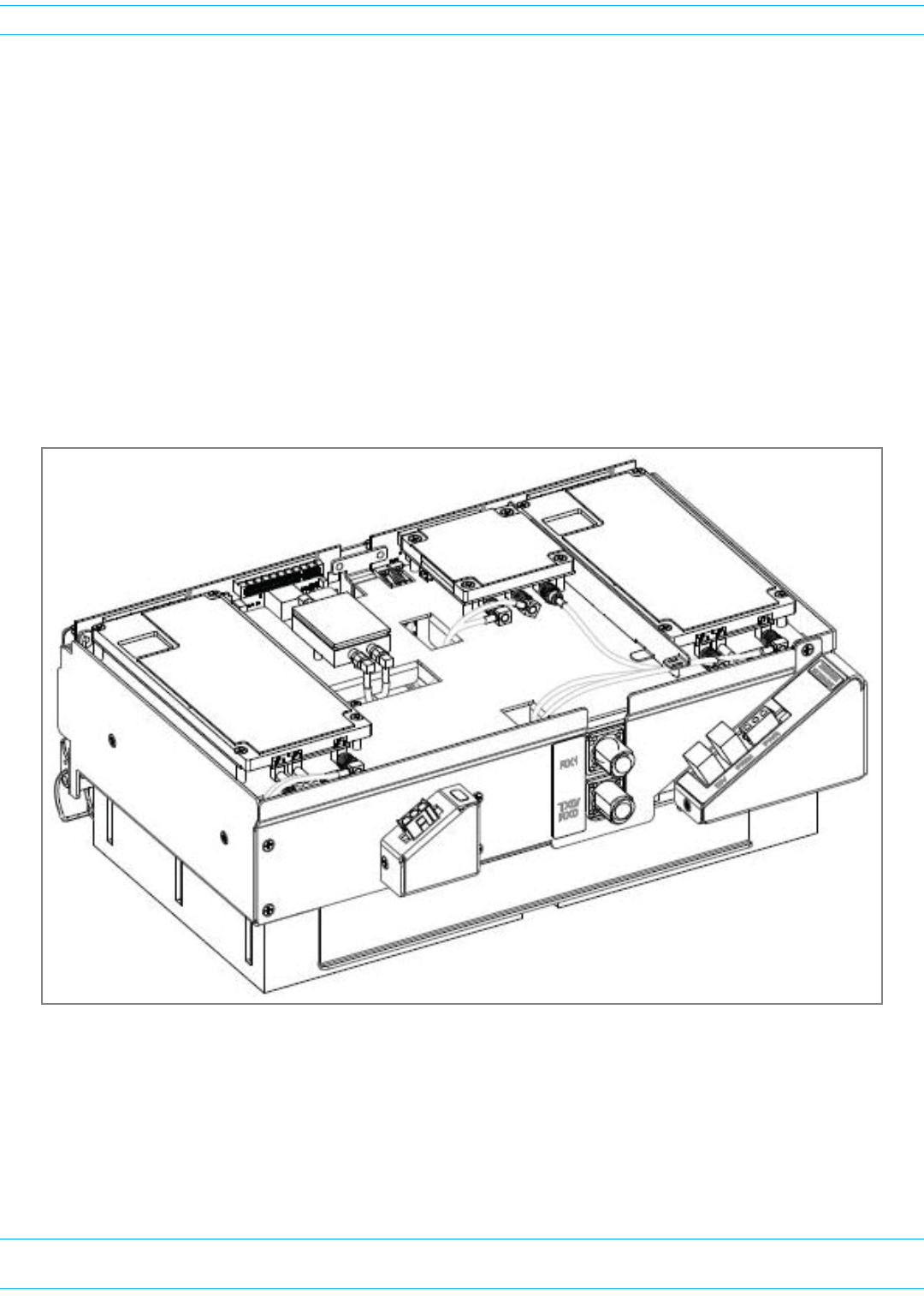
RF MODULE COMPONENTS
Figure5showstypicalRFModulecomponents,usingtheSingle-BayRFModuleasanexample,and
Figure6showsthecomponentsofanHDMRFModule.
Figure 5. Single-Bay RF Module Components
Figure 6. HDM RF Module Components
MounƟng
latch
MounƟng
hook
Duplexer Power Amplifier (PA)
DARTs
NOTE: The RDI is internal to the RF Module and is therefore not shown.
LNA
(inside the Duplexer caviƟy)
Duplexers Power Amplifier
MounƟng latch
MounƟng hook
Tx and Rx Cards DPM

FWPP-501-01 Issue 1 • 320000117795 Rev A FlexWave Prism Remote Unit and HDM RF Module Installation Guide
© March 2016 CommScope, Inc. Page 19
Overview of RF Modules for Prism Remote Units
Linear Power Amplifiers
TheLinearPowerAmplifier(LPA)isahighqualitybroadbandRFamplifierusedforachievingPrism
product-ratedpowerfortheRemoteUnitTxforwardpathRF.ThePAsarepass-bandspecific,withthe
maximumcompositeTxpowerlevelslistedinTable13forSingle-Card,Dual-Card,andHDMRF
ModulesandTable14onpage20forLegacyDual-Bay40WRFModules.
TheLPAishousedwithintheRFModule,andisnotfieldserviceable.
Table 13. LPA Maximum Composite Tx Power Levels for Single-Card, Dual-Card, and HDM RF Modules
Bandwidth (MHz) supported across entire spectrum*
Passband Maximum
dBmWatts
HDM
Single Super DART Classic
DART
Dual
SuperDART
Dual/MIMO SISO
700 LTE Lower ABC 43 20 18 18 18 NA NA
700 LTE Upper C
43 20 10 10 10 NA NA
46 40 10 10 10 NA NA
800 SMR 43 20 7 7 NA 18 NA
850 Cellular
43 20 25 25 NA 25 NA
46 40 25 25 NA 25 NA
900 EGSM 40 10 35 35 35 NA NA
900 PGSM 40 10 25 25 25 NA NA
900 SMR 38 6.5 NA NA NA 5 NA
1800 DCS 42 15.8 35 NA 39 NA 75
1900 PCS 43 20 35 65 39 NA 70
46 40 NA 65 39 NA 70
2100 AWS
43 20 35 45 39 NA 45
46 40 NA 45 39 NA 45
2100 UMTS 42 15.8 35 NA 39 NA 60
2300 WCS 43 20 10 10 10 NA NA
2500 TDD Low
2500 TDD High 43 20 NA 75 75 NA 75
* The International bands (1800 DCS, 2100 UMTS, 2600 MIMO) Dual/MIMO RF Modules only support 35 MHz contiguous, as
opposed to 35 MHz non-contiguous for PCS and AWS Dual/MIMO RF Modules.

FlexWave Prism Remote Unit and HDM RF Module Installation Guide 320000117795 Rev A • FWPP-501-01 Issue 1
Page 20 © March 2016 CommScope, Inc.
Overview of RF Modules for Prism Remote Units
NOTE: Industry Canada 20 dB Pass Band Model Number FWP-C4MT000MOD Cellular 850 MHz =
26.3 MHz and the PCS 1900 = 66.8 MHz.
Duplexer and Low Noise Amplifier
TheRFModuleprovidestheRemoteUnitwithaninternalDuplexerthatisoptimizedtoprovidethe
desiredRFband-passfilteringandin-bandequipmentisolationbetweenFWDandREVpaths.The
Duplexerprovidesthefilteringnecessarytothetransmitandreceivepathstoandfromtheconnected
antenna.
TheDuplexerfortheSingle-andDual-BayRFModulesandtheLegacyDual-Bay40WRFModules
containsuptotwoREVpathLowNoiseAmplifiers(LNAforPRIand/orSECreversepaths).
TheDuplexerforanHDMRFModuledoesnothaveaLowNoiseAmplifier.
Duplexersarenotfieldserviceable.
Digital Processing Module
TheDigitalProcessingModule(DPM)isfoundonlyintheHDMRFModules.TheDPMprovidesthe
primaryprocessingandlogicfunctionsfortheHDMRFModule.Italsoprovidestheprimarypower
interfacefortheHDMRFModule,andconversionofthenative28Vdcvoltagetolowervoltagesas
necessaryforfunctionality.
TheDPMhasaTransmit(Tx)BoardandaReceive(Rx)Board:
•TxBoard—providesbandspecificfilteringfortheintendedTransmitpath.
•RxBoard—providesbandspecificfilteringfortheintendedReceivepath.
Cables
AlwaysprovidedateachRFModuleshelfarefivecables:
•twoHigh-SpeedDataCables,whichinthisdocumentarereferredtoasLVDS(Low-Voltage
DifferentialSignaling)cables
•twoRFCables(TX0/RX0)and(TX1/RX1)
•onePower(PWR)Cable.
TheRFModulecablesthatarepre-installedinthePRUconnecttothecorrespondingconnectorsonthe
RFModule.TheRFModulecablescorrelatetotheantennaconnectorsonthebottomoftheRemoteUnit
chassis.
Table 14. LPA Maximum Composite Tx Power Levels for Legacy Dual-Bay 40W RF Modules
Passband Maximum dBm Watts Bandwidth (MHz) supported across
entire spectrum Classic DART
PCS 1900 +46 40 35
AWS 2100 +46 40 35
FWPP-501-01 Issue 1 • 320000117795 Rev A FlexWave Prism Remote Unit and HDM RF Module Installation Guide
© March 2016 CommScope, Inc. Page 21
Overview of RF Modules for Prism Remote Units
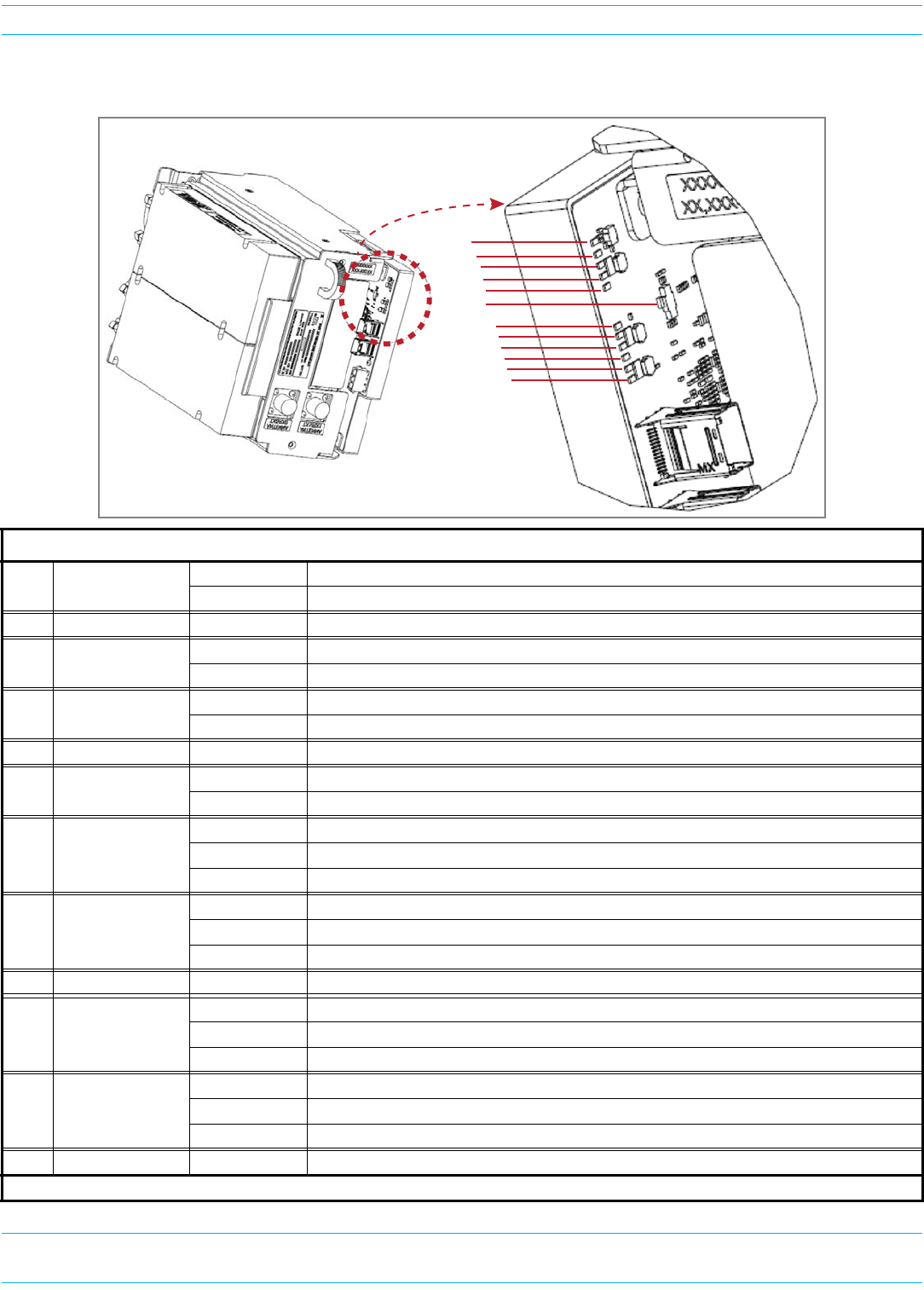
LEDS on Narrowband HDM RF Modules
Ref # LED LED Color Description
1DPM Power Green HDM RF Module is powered on.
Red Problem with the HDM RF Module power.
2FPGA Status Blinking Green Blinks as heartbeat of the HDM RF Module.
3LVDS 0 Status Green Primary LVDS Dynamic Phase Alignment (DPA) connector is operating as expected.*
Red Primary LVDS DPA connector is not operating as expected.
4LVDS 1 Status Green Primary LVDS Dynamic Phase Alignment (DPA) connector is operating as expected.*
Red Primary LVDS DPA connector is not operating as expected.
5DSP/GC Status —Not used.
6FPGA Load Status Red FPGA is in startup mode.
Off FPGA load is complete.
7TXA Status
Green All synthesizers are locked.
Blinking Green One or more synthesizer is unlocked.
Red Overflow on RX.
8RXA Status
Green All synthesizers are locked.
Blinking Green One or more synthesizer is unlocked.
Red Overflow on RX.
9TMA A Status —Not used.
10 TXB Status
Green All synthesizers are locked.
Blinking Green One or more synthesizer is unlocked.
Red Overflow on RX.
11 RXB Status
Green All synthesizers are locked.
Blinking Green One or more synthesizer is unlocked.
Red Overflow on RX.
12 TMA A Status —Not used.
* LED is only applicable to the Primary connector; it is not tied to the status of the Secondary DPA connector.
1
2
3
4
5
6
7
10
11
12
8
9
FlexWave Prism Remote Unit and HDM RF Module Installation Guide 320000117795 Rev A • FWPP-501-01 Issue 1
Page 22 © March 2016 CommScope, Inc.
Overview of RF Modules for Prism Remote Units
LEDS on Wideband and Fullband HDM RF Modules
Ref # LED LED Color Description
1DPM Power Green HDM RF Module is powered on.
Red Problem with the HDM RF Module power.
2FPGA Status —Not used.
3LVDS 0 Status —Not used.
4LVDS 1 Status —Not used.
5DSP/GC Status —Not used.
6FPGA Load Status Red FPGA is in startup mode.
Off FPGA load is complete.
7TXA Status
Green All synthesizers are locked.
Blinking Green One or more synthesizer is unlocked.
Red Overflow on RX.
8RXA Status
Green All synthesizers are locked.
Blinking Green One or more synthesizer is unlocked.
Red Overflow on RX.
9TXB Status
Green All synthesizers are locked.
Blinking Green One or more synthesizer is unlocked.
Red Overflow on RX.
10 RXB Status
Green All synthesizers are locked.
Blinking Green One or more synthesizer is unlocked.
Red Overflow on RX.
1
2
3
4
5
6
7
8
9
10
FWPP-501-01 Issue 1 • 320000117795 Rev A FlexWave Prism Remote Unit and HDM RF Module Installation Guide
© March 2016 CommScope, Inc. Page 23
Configuring the System with RF
CONFIGURING THE SYSTEM WITH RF
ThefollowingsectionsdescribehowtocorrectlypairRFModuleswithPRUslots,cables,andAntenna
connectors.
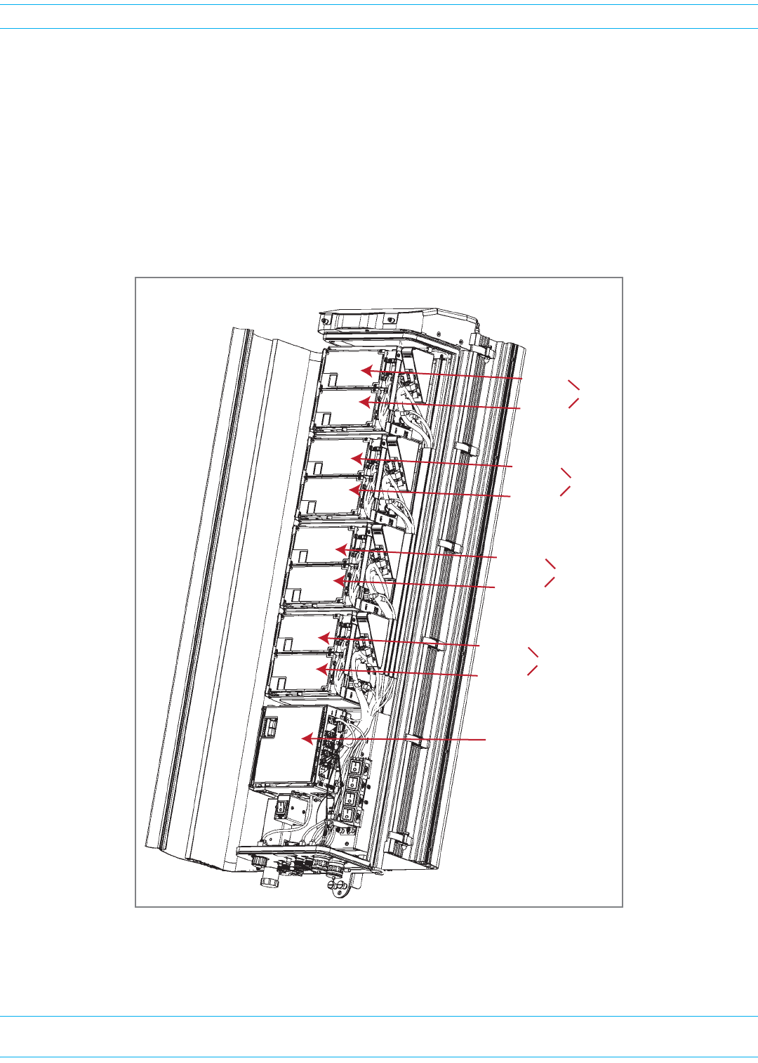
RF GROUP ASSIGNMENTS FOR PRU RF MODULE BAYS
APRUcomprisesfromonetofourRFModulebays.Figure7illustratesthenumberingofRFModule
baysandDARTs.
Figure 7. RF Modules Bays in a PRU
Quad-Bay Remote Unit with Single-Card RF Modules
SeRF Module
DART 7
DART 8
Bay D
DART 5
DART 6
Bay C
DART 3
DART 4
Bay B
DART 1
DART 2
Bay A

FlexWave Prism Remote Unit and HDM RF Module Installation Guide 320000117795 Rev A • FWPP-501-01 Issue 1
Page 24 © March 2016 CommScope, Inc.
Configuring the System with RF
Table15listshowtheFlexWavePrismEMSreferencestheRFgroupassignmentsandcorresponding
componentsofeachRFModule.
NOTE: For Classic dual position 40W RF Modules only: in a dual LPA system, the Configure Remote
Forward Gain page shows two values for the LPA status, one for each LPA. Changing the LPA
Mode or resetting the LPA applies to both LPAs at the same time.
CAUTION! Should your system experience an LPA problem, refer to Table 15 to ensure that you apply
new settings or troubleshoot the correct RF Module.
Table 15. Remote Unit RF Group Assignments (from Top/Down)
Physical RF
Bay DART Number
LNA Number
LPA Number
for Single LPA
LPA Number
for Dual LPAs
Power
Detector
Number for
Single PD
Power
Detector
Number for
Dual PDs
Primary Diversity
D
88
7
8
7
8
77 7 7
C
66
5
6
5
6
55 5 5
B
44
3
4
3
4
33 3 3
A
22
1
2
1
2
11 1 1
NOTE: For software releases prior to 7.3, the LPAs were labeled as 1, 2, 3, and 4.
FWPP-501-01 Issue 1 • 320000117795 Rev A FlexWave Prism Remote Unit and HDM RF Module Installation Guide
© March 2016 CommScope, Inc. Page 25
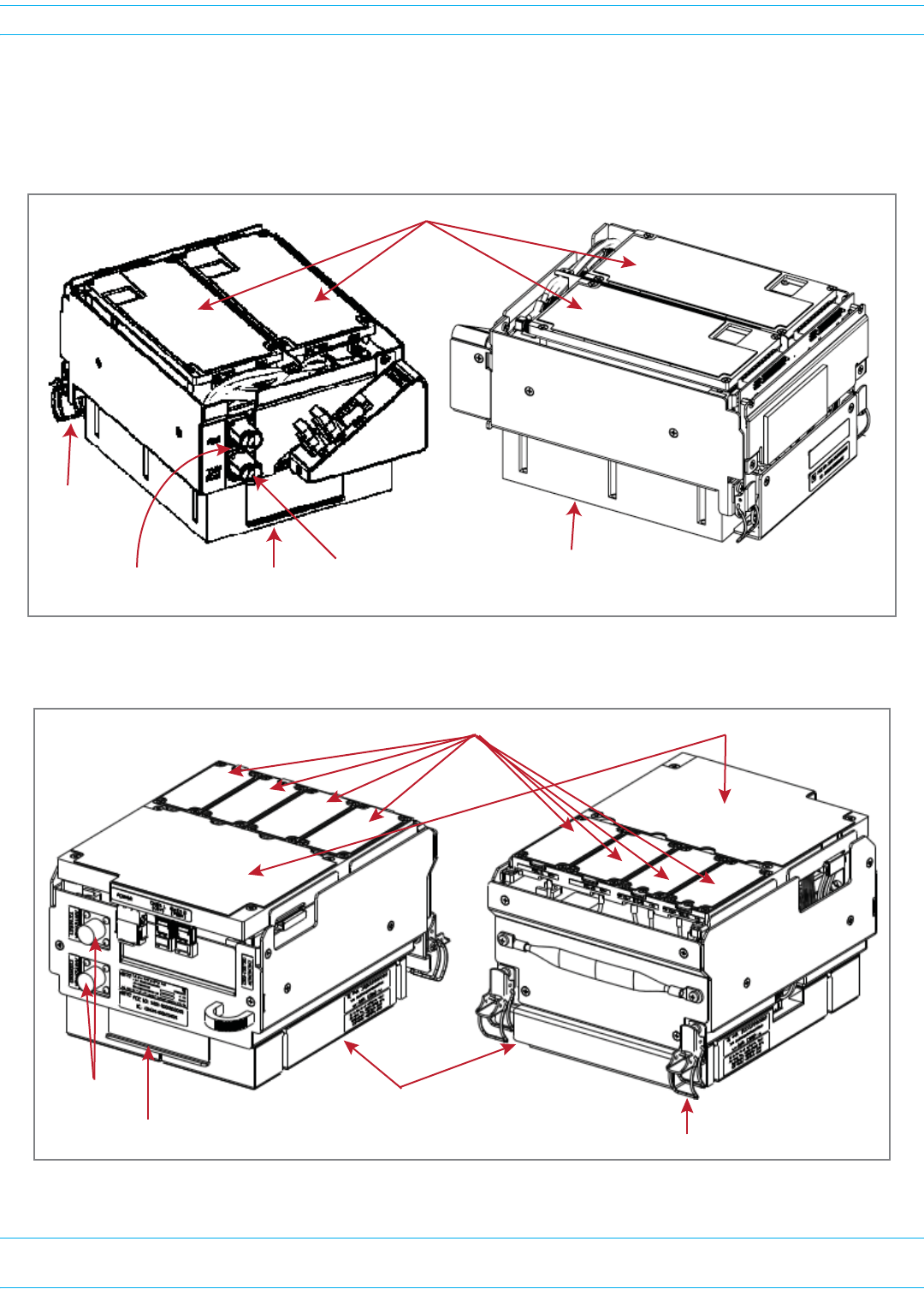
Configuring the System with RF
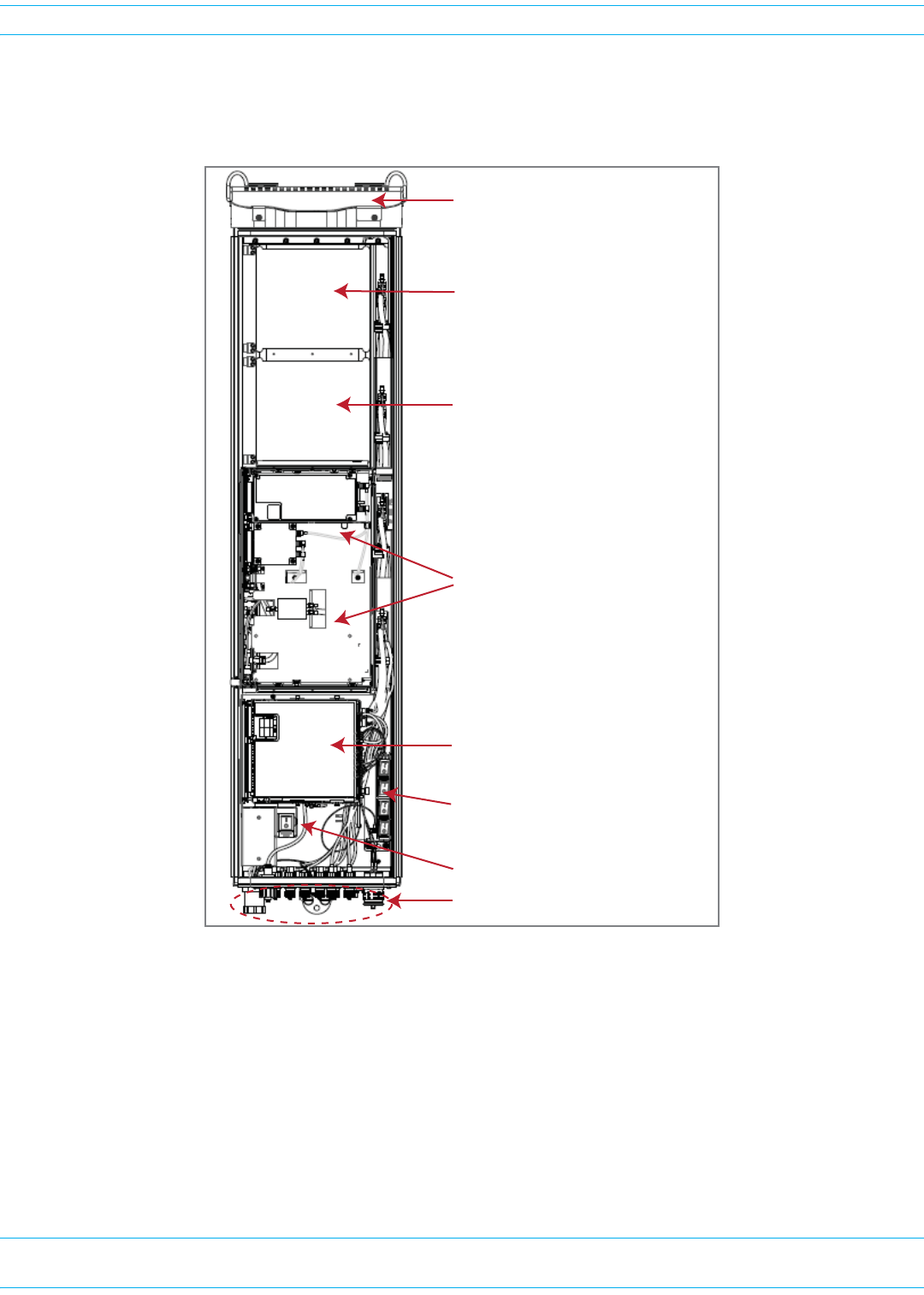
TheLegacyDual-Bay40WRFModuleoccupiestwobaysinaPRU.Figure8showsthemaincomponents
inaPRUenclosure,withaLegacy40WRFModuleoccupyingBaysAandB.ThecontrollingDARTwill
alwaysbeintheupperbay(BorD),andthesecondLPAisalwaysinthelowerbay(AorC).
Figure 8. Legacy Dual-Bay 40W RF Module in a Quad-Bay PRU
NOTE: If a Legacy Dual-Bay 40W RF Module AWS 2100 and a Legacy Dual-Bay 40W RF Module PCS
1900 are both installed in a Quad-Bay PRU, it is recommended that the PCS 1900 be installed
in upper-most bay, and the AWS 2100 be installed in the lower-most bay.
NOTE: To accommodate two-bay modules, you need to remove a module bay shelf as described in
"Dual-Bay Modules Only—Remove the Module Bay Shelf” on page 85.
Legacy Dual-Bay 40W RF Module
in Bay B (upper slot) and
Bay A (lower slot) with the
controlling DART in Bay B
AC or DC power switch
Four DC power switches
SeRF Module and Power supplies
Bay C (empty for future use)
Bay D (empty for future use)
Fans
ConnecƟvity panel with Status LED

FlexWave Prism Remote Unit and HDM RF Module Installation Guide 320000117795 Rev A • FWPP-501-01 Issue 1
Page 26 © March 2016 CommScope, Inc.
Configuring the System with RF
UNDERSTANDING RF CABLE RULES
•WheninstallingaDiversity,MIMOorDual-BandRFModule,bothRFcableslabeledMODNTX0/RX0
andMODNTX1/RX1shallbeconnectedtotheN-StyleconnectionsoftheRFModule.Notethatolder
labelingschemesused“PRI”and“DIV”.Tomatcholdlabelingschemestocurrentlabeling:
•WheninstallingaNon-DiversityorSISORFModule,oranSMR800/900Dual-BandDual-BayRF
Module:
–ConnecttheMODNTX0/RX0cabletothesingleavailableN-StyleRFConnectionoftheRF
Module.
–ConstraintheMODNTX1/RX1cablewiththeexistingcablesusingatiewraporsimilarly
acceptedfastenersoitcannotbepinchedorpreventtheRemoteUnitdoorfromclosing.Donot
cutorattempttootherwiseremovethisRFCable.
•RFcablesarehand-malleable;however,cablesmustadheretoaminimumbendradiusof1-inch
fromtheoutletoftheintegratedcableguidetotherespectiveN-StyleRFconnectionontheRF
Module.
RF Module Cables and Supported Bay Use for Single-Card, Dual-Card,
and HDM RF Modules
TheRFcableandconnectorlabelscorrespondtotheRFModulebaysintheRemoteUnitchassis,where
MOD AisthebottombayandMOD Disthetopbay.
•ThecablesandconnectorshavecorrespondinglabelsasshowninTable16onpage27for
Single-Card,Dual-Card,andHDMRFModules.ForDual-Bayinstallations,theRFcablesand
connectorsarelabeledasMOD N TX0/RX0andMOD N TX1/RX1,whereNreferstothetopbayofthe
double-bayinstallation.Forexample:
–ForaDual-BayinstallationinaQuad-BaychassisinwhichtheRFModuleisinstalledintheBay
DandBayCcombination,theRFcablesandconnectorsarelabeledasMOD D TX0/RX0andMOD
D TX1/RX1.
–ForaDual-BayinstallationinaTri-BaychassisinwhichtheRFModuleisinstalledintheBayB
andBayAcombination,theRFcablesandconnectorsarelabeledasMOD B TX0/RX0andMOD B
TX1/RX1.
•Table16onpage27alsoshowswhichRFModuletypecanbeinstalledinwhichPRUbayorbay
combination.
Old Label New Label
PRI TX0/RX0
DIV TX1/RX1

FWPP-501-01 Issue 1 • 320000117795 Rev A FlexWave Prism Remote Unit and HDM RF Module Installation Guide
© March 2016 CommScope, Inc. Page 27
Configuring the System with RF
RF Module Cables and Supported Bay Installations for Legacy Dual-Bay
40W RF Modules
ThecablesandconnectorshavecorrespondinglabelsasshowninTable17onpage28forLegacy
Dual-Bay40WRFModules.Table17onpage28alsoshowswhichRFModuletypecanbeinstalledin
whichPRUbay(s)whena40WDual-BayRFModuleispartoftheRFModulemixinaPRUchassis.The
Single-BaychassisisnotincludedinTable17onpage28.
ForDual-Bayinstallations,theRFcablesandconnectorsarelabeledasMOD N TX0/RX0andMOD N
TX1/RX1,whereNreferstothetopbayofthedouble-bayinstallation.Forexample:
•ForaDual-BayinstallationinaQuad-BaychassisinwhichtheRFModuleisinstalledintheBayD
andBayCcombination,theRFcablesandconnectorsarelabeledasMOD D TX0/RX0andMOD D
TX1/RX1.
•ForaDual-BayinstallationinaTri-BaychassisinwhichtheRFModuleisinstalledintheBayCand
BayBcombination,theRFcablesandconnectorsarelabeledasMOD C TX0/RX0andMOD C TX1/RX1.
Table 16. Supported Bay Use and RF Antenna Labels for Single-Card, Dual-Card, and HDM RF Modules
(From Top of Remote Unit Chassis Down)
Supported Bay
Configurations
for Single-Bay RF
Modules
Supported Bay Combinations
for Dual-Bay RF Modules
RF Module Cable,
RF Module
Connector, and
Remote Antenna
Connector Label
Function
Supported
Bays in
Dual-Bay
Chassis
Supported
Bays in
Tri-Bay
Chassis
Supported
Bays in
Quad-Bay
Chassis
Bay D MOD D N/A N/A
MOD D
Mod D TX0/RX0 Transmit RF power and primary/Path 1 receive
to/from the antenna for RF Module D
Mod D TX1/RX1 Transmit RF power and secondary/Path 2
receive to/from the antenna for RF Module D
Bay C MOD C N/A MOD C
Mod C TX0/RX0 Transmit RF power and primary/Path 1 receive
to/from the antenna for RF Module C
Mod C TX1/RX1 Diversity receive/Path 2 for Transmit RF power
and secondary/Path 2 receive to/from the
antenna for RF Module C
Bay B MOD B
M
OD BMOD BMOD B
Mod B TX0/RX0 Transmit RF power and primary/Path 1receive
to/from the antenna for RF Module B
Mod B TX1/RX1 Transmit RF power and secondary/Path 2
receive to/from the antenna for RF Module B
Bay A MOD A
Mod A TX0/RX0 Transmit RF power and primary/Path 1 receive
to/from the antenna for RF Module A
Mod A TX1/RX1 Transmit RF power and secondary/Path 2
receive to/from the antenna for RF Module A

FlexWave Prism Remote Unit and HDM RF Module Installation Guide 320000117795 Rev A • FWPP-501-01 Issue 1
Page 28 © March 2016 CommScope, Inc.
Configuring the System with RF
Table 17. Supported Bay Assignments and RF Antenna Labels for Legacy Dual-Bay 40W RF Modules
(From Top of Remote Unit Chassis Down)
Supported Bay Combinations for Legacy 40W Dual-Bay RF Modules RF Module
Cable,
RF Module
Connector, and
Remote Antenna
Connector Label
Function
Dual-Bay Tri-Bay Tri-Bay Quad-Bay
Bay D N/A N/A N/A
MOD D
MOD D
MOD C
Mod D TX0/RX0
Transmit RF power and
primary/Path 1 receive
to/from the antenna for RF
Module D
Mod D TX1/RX1
Transmit RF power and
secondary/Path 2 receive
to/from the antenna for RF
Module D
Bay C N/A MOD C
MOD C
MOD C
Mod C TX0/RX0
Transmit RF power and
primary/Path 1 receive
to/from the antenna for RF
Module C
Mod C TX1/RX1
Transmit RF power and
secondary/Path 2 receive
to/from the antenna for RF
Module C
Bay B
MOD B MOD B MOD B MOD B
MOD B
Mod B TX0/RX0
Transmit RF power and
primary/Path 1receive
to/from the antenna for RF
Module B
Mod B TX1/RX1
Transmit RF power and
secondary/Path 2 receive
to/from the antenna for RF
Module B
Bay A MOD A MOD A
Mod A TX0/RX0
Transmit RF power and
primary/Path 1 receive
to/from the antenna for RF
Module A
Mod A TX1/RX1
Transmit RF power and
secondary/Path 2 receive
to/from the antenna for RF
Module A
NOTE: For Dual Module installations the center module shelf needs to be removed; see "Dual-Bay Modules Only—Remove the
Module Bay Shelf” on page 85.
NOTE: Install the Legacy Dual-Bay 40W RF Module in the lower-most bay in the chassis. If, however, if two Legacy Dual-Bay 40W
RF Modules are present, install the 2100 Module in the lower-most Bay and the 1900 Module in the upper-most Bay.

FWPP-501-01 Issue 1 • 320000117795 Rev A FlexWave Prism Remote Unit and HDM RF Module Installation Guide
© March 2016 CommScope, Inc. Page 29
Install the Prism Remote Unit
INSTALL THE PRISM REMOTE UNIT
ThissectiontellsyouhowtoinstallaPrismRemoteUnit(PRU).IfthePRUisalreadyinstalledandyou
needtoaddoneormoreRFModules,goto"InstalltheRFModule(s)”onpage80.
PLANNING FOR A PRISM REMOTE UNIT INSTALLATION
BeforeyouunpackthePRU,youshouldfirstplanforwhereitwillbemountedandcollectthetoolsand
suppliesthatarerequiredtomountthePRUandthenconnectittoaPrismsystem.
NOTE: Installation of the Prism Remote Unit may proceed separately from the installation of the
corresponding Host Unit.
Safety Precautions
CAUTION! This is restricted access equipment and only qualified service personnel should open, service, or
operate this equipment using appropriate tools.
CAUTION! Wet conditions increase the potential for receiving an electrical shock when installing or using
electrically-powered equipment. To prevent electrical shock, never install or use electrical equipment
in a wet location or during a lightning storm.
CAUTION! Contact with overhead cables, especially electric power cables, could cause serious personal injury or
death. Before beginning the installation, check the location of all overhead wires and cables and take
precautions to avoid accidental contact.
CAUTION! Exterior surfaces of the Prism Remote Unit may be hot. Use caution during servicing.
CAUTION! This equipment uses a Class 1 Laser according to FDA/CDRH rules. Laser radiation can seriously
damage the retina of the eye. Do not look into the ends of any optical fiber. Do not look directly into
the optical transceiver of any digital unit or exposure to laser radiation may result. An optical power
meter should be used to verify active fibers. A protective cap or hood MUST be immediately placed
over any radiating transceiver or optical fiber connector to avoid the potential of dangerous amounts
of radiation exposure. This practice also prevents dirt particles from entering the adapter or
connector.
CAUTION! This system is an RF Transmitter and continuously emits RF energy. Maintain 3 foot (91.4 cm)
minimum clearance from the antenna while the system is operating. Wherever possible, shut down
the RAN before servicing the antenna.
CAUTION! Always allow sufficient fiber length to permit routing of patch cords and pigtails without severe bends.
Fiber optic patch cords or pigtails may be permanently damaged if bent or curved to a radius of less
than 2 inches (5.1 cm).
CAUTION! Always use an Electro-Static Discharge (ESD) wrist strap whenever you work with the Prism Remote
Unit or its components. Make sure that it maintains maximum contact with bare skin. ESD grounding
straps are available with banana plugs, metal spring clips, or alligator clips. To ensure adequate
grounding, connect the ESD wrist strap to any bare metal surface of the Prism Remote Unit chassis
(which may require that you scrape off some of its protective coating), or to the Dual-Ground
Connector at the bottom of the unit. For information on the Dual-Ground Connector, see "Ports and
Connectors” on page 7.
CAUTION! Service personnel must confirm that the perimeter gasket and door-to-door gaskets are in place when
closing the Prism doors after servicing.

FlexWave Prism Remote Unit and HDM RF Module Installation Guide 320000117795 Rev A • FWPP-501-01 Issue 1
Page 30 © March 2016 CommScope, Inc.
Install the Prism Remote Unit
Mounting Plans
ThePRUhasalowprofiledesignthatrequiresminimalrealestateforinstallation.Thebasicdimensions
andweightsofthePRUarelistedinTable19onpage31andTable18onpage31.
ThePRUshouldbemountedonautilitypole,mast,oronaflatsurface.AMountingBracketshipswith
eachRemote.Installationconsistsofsecuringthebrackettothemountingsurface(wood,concrete,or
steel)andthenhangingtheunitfromthebracket.thePRUshouldonlybemountedinarestrictedaccess
location.
BeforemountingthePRU,makesurethatthefollowingrequirementsaremet.
•ThePRUmust
–beinstalledonlyinarestricted-accesslocation
–mustbelocatedasspecifiedinthesystemdesignplan(notdocumentedhere).Ifasystemdesign
planhasnotbeenprepared,consultwiththeTechnicalSupportforWirelessProductsteamfor
assistance(see"DCCSGlobalTechnicalSupport”onpage119).
–musthavereadyaccesstothespecifiedACorDCpowersource.
•IfyoumountthePRUinahorizontalposition,youmustmountitataslightangle,withthetopofthe
PRUchassisangledhigherthanthebottom,whichcreatesaslopethatallowswaterorsnowtorun
offthePRUchassis.Ifitismountedindoors,nosloperequired.
•IfyoumountthePRUinanupside-downhorizontalposition(i.e.,aceilingmount),attachsafety
leashesthatcansupporttheweightofafullypopulatedchassis(seeTable18onpage31).
•Thesitechosenmust
–conformtoalllocalcodes;requiredpermitsmustbeobtainedpriortomountingaPRU
–complywiththeunitenvironmentalspecifications
–beopentofreeairspaceonthebottom(cableentryend),thetop,thefront,andbothsides
–allowadequateclearanceatthebottomofthePRUtoprovideaccessforattachingcablesandfor
viewingtheLEDindicator
–provide18inches(45.7cm)ofclearanceonthefrontandbothsidesofthePRUtoallowdoors
tobeopenedforserviceandtoallowfreeaircirculation
–beabletobearthesizeandweightofthePRUenclosure,seeTable19onpage31andTable18
onpage31
FWPP-501-01 Issue 1 • 320000117795 Rev A FlexWave Prism Remote Unit and HDM RF Module Installation Guide
© March 2016 CommScope, Inc. Page 31
Install the Prism Remote Unit
Figure9onpage32throughFigure12onpage35providethespacingdimensionsforbandsand
bracketmountingbolts.
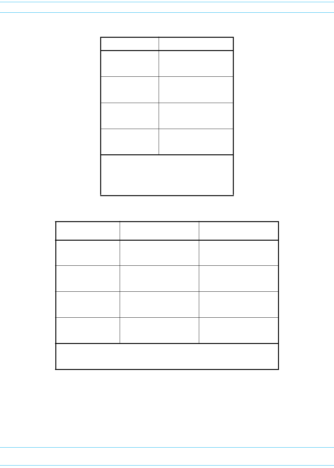
Table 18. Prism Remote Unit Weights (1)
PRU Model Unpopulated Populated
Single-Bay
Pounds
Kilograms
65 83
29 38
Dual-Bay
Pounds
Kilograms
81 117
37 53
Tri-Bay
Pounds
Kilograms
97 151
44 68
Quad-Bay
Pounds
Kilograms
116 188
53 85
(1) “Unpopulated” weight includes the SeRF
Module and the Solar shields, which are always
present. “Populated” weight is the weight of
the chassis that has the SeRF Module and RF
Modules installed.
Table 19. Prism Remote Unit Enclosure Dimensions (1)
PRU Model Height Width (2)
Depth See…
Single-Bay
Inches
Centimeters
25.2 12.211.2
64 30.9928.45
Figure 9 on page 32
Dual-Bay
Inches
Centimeters
33.2 12.211.2
84.3 30.9928.45
Figure 10 on page 33
Tri-Bay
Inches
Centimeters
41.2 12.2 11.2
104.6 30.9928.45
Figure 11 on page 34
Quad-Bay
Inches
Centimeters
52.4 12.2 11.2
133.10 30.99 28.45
Figure 12 on page 35
(1) To have adequate clearance to open the PRU chassis door, allow a minimum of 18
inches at the left, right and front of each PRU.
(2) Dimension for width includes the mounting brackets.
FlexWave Prism Remote Unit and HDM RF Module Installation Guide 320000117795 Rev A • FWPP-501-01 Issue 1
Page 32 © March 2016 CommScope, Inc.
Install the Prism Remote Unit
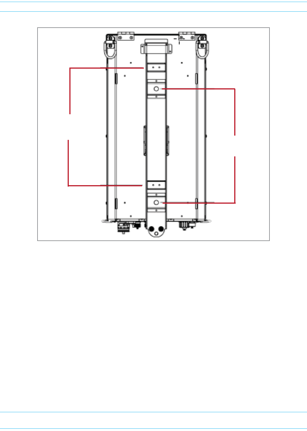
Figure 9. Mounting Dimensions for Single-Bay PRUs
14.5” (36.83 cm)
Top Band to BoƩom Band
14.0” (35.56 cm)
Top Bolt to BoƩom Bolt
FWPP-501-01 Issue 1 • 320000117795 Rev A FlexWave Prism Remote Unit and HDM RF Module Installation Guide
© March 2016 CommScope, Inc. Page 33
Install the Prism Remote Unit
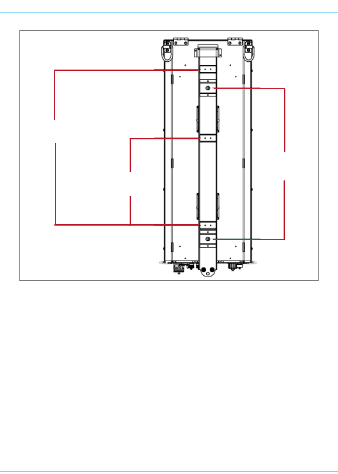
Figure 10. Mounting Dimensions for Dual-Bay PRUs
21.7” (55.118 cm)
Top Band to BoƩom Band
21.0” (53.34 cm)
Top Bolt to BoƩom Bolt
12.1” (30.734 cm)
MiddleBand to BoƩom Band
FlexWave Prism Remote Unit and HDM RF Module Installation Guide 320000117795 Rev A • FWPP-501-01 Issue 1
Page 34 © March 2016 CommScope, Inc.
Install the Prism Remote Unit
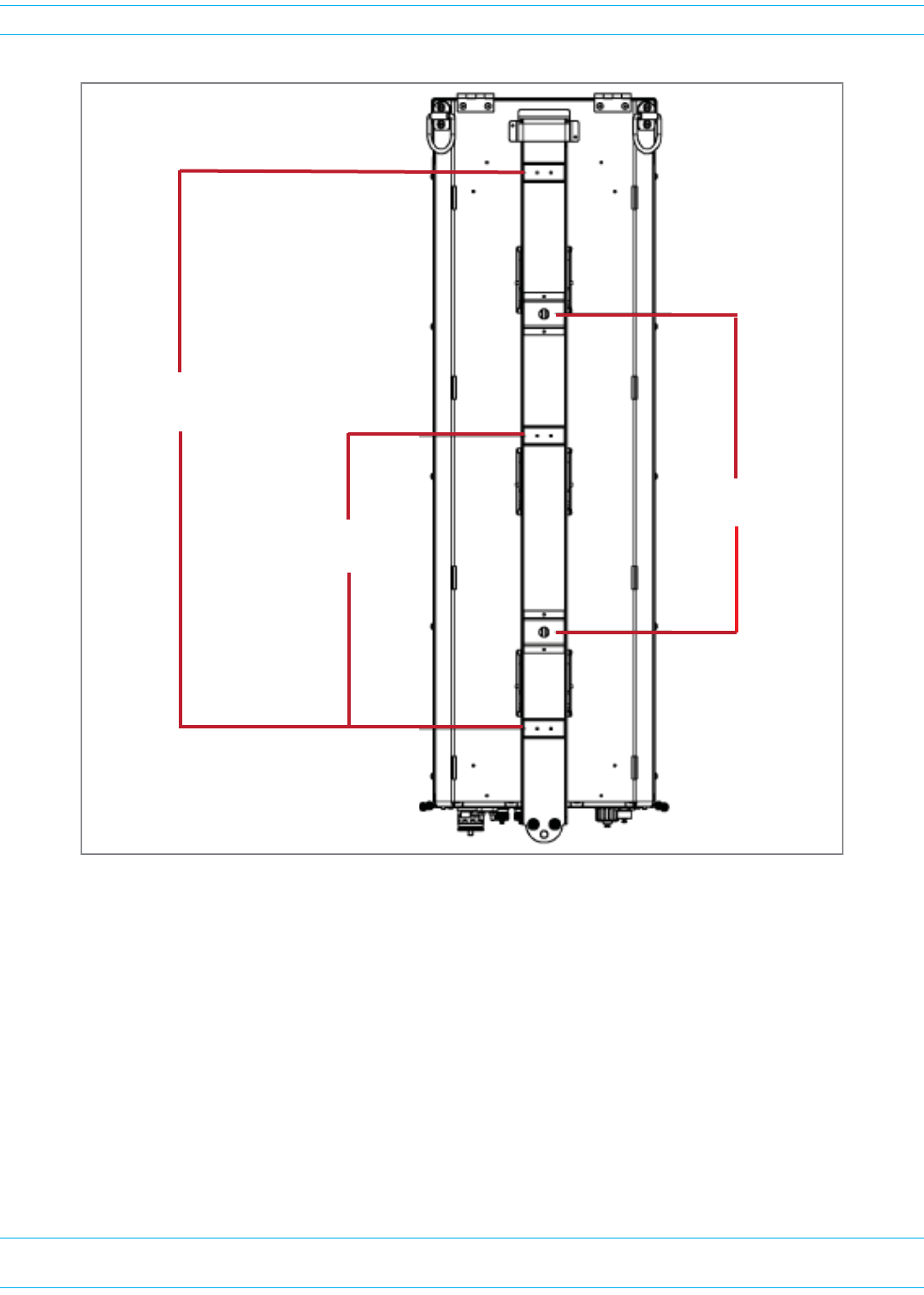
Figure 11. Mounting Dimensions for Tri-Bay PRUs
30.6” (77.724 cm)
Top Band to BoƩom Band
17.5 (44.45 cm)
Top Bolt to BoƩom Bolt
16.1” (40.894 cm)
MiddleBand to BoƩom Band
FWPP-501-01 Issue 1 • 320000117795 Rev A FlexWave Prism Remote Unit and HDM RF Module Installation Guide
© March 2016 CommScope, Inc. Page 35
Install the Prism Remote Unit
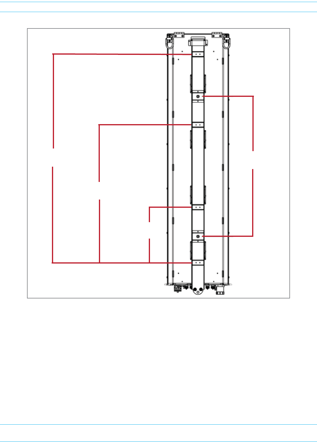
Figure 12. Mounting Dimensions for Quad-Bay PRUs
41.7” (105.918 cm)
Band 1 to BoƩom Band 28.0” (71.12 cm)
Top Bolt to BoƩom Bolt
27.6” (70.104 cm)
Band 2 to BoƩom Band
11.1” (28.194 cm)
Band 3 to BoƩom Band
FlexWave Prism Remote Unit and HDM RF Module Installation Guide 320000117795 Rev A • FWPP-501-01 Issue 1
Page 36 © March 2016 CommScope, Inc.
Install the Prism Remote Unit
Installation Tools and Supplies
ThetoolsandanyadditionalmaterialsrequiredforinstallandmountthePRUaredependentonthe
mountinglocation.
Tools Required for All Mounting Methods
TheMountingBracketshipswiththePRU—itsecuresthePRUtoitspackingcrate.Allinstallations
requireatleastoneeachofthefollowing,whichmustbeprovidedbytheinstaller:
•tapemeasure
•pencilorothermarkingdevice
•3/8-inchFlat-Bladescrewdriver
•liftingequipmentforPRU.
Additional Tools and Supplies Required for Steel-Pole Mounting
WhenmountingthePRUtoasteelpole,inadditiontothesupplieslistedin"ToolsRequiredforAll
MountingMethods”onpage36thefollowingsuppliesareneeded:
•onehammer,>16-ounces
•oneStrapTensioning/ClampingTool(UlineModelNo.H-1273,orequivalent)
•Table20showsthenumberofstainless-steelstrapsandstainless-steelbucklesrequiredforeach
PRUtype,inwhichyoumusthavethesamenumberofbucklesasstraps.
–Use1/2-inchto3/4-inch201,301,304or316Stainless-SteelStrappingwithaminimumtensile
strengthof1500lbs(UlineModelNo.S-11329,orequivalent).
–UseStainless-SteelBucklesdesignedspecificallyfortheabovementionedstrapping(Uline
ModelNo.S-11331,orequivalent).
Table 20. Required Stainless-Steel Bands for Steel-Pole Mounting
CommScope Catalog Number Number of Bands Required for Installation
FP4-XXXXX0021XXRU - Quad-Bay Remote 4
FP3-XXXXX0021XXRU - Tri-Bay Remote 3
FP2-XXXXX0021XXRU - Dual-Bay Remote
FP1-XXXXX0021XXRU - Single-Bay Remote 2

FWPP-501-01 Issue 1 • 320000117795 Rev A FlexWave Prism Remote Unit and HDM RF Module Installation Guide
© March 2016 CommScope, Inc. Page 37
Install the Prism Remote Unit
Additional Tools and Supplies Required for Wood-Pole Mounting
WhenmountingthePRUtoawoodpole,inadditiontothesupplieslistedin"ToolsRequiredforAll
MountingMethods”onpage36,thefollowingsuppliesareneeded:
•oneelectricdrill,1/2-inchorlarger
•one1/2-inchdrillbit
•two1/2-inchsquare-headthrough-boltorequivalentthatislongenoughtoextendthroughthe
utilitypole
•two1/2-inchsquarenutorequivalent
•two1/2-inchsquarewasher
•oneormoreappropriately-sizedwrenchesforthrough-bolts
•oneadjustablewrench
Additional Tools and Supplies Required for Flat-Surface Mounting
•oneelectricdrill,1/2-inchorlarger
•one5/8-inchwrench
•two1/2-inchflatwashers
•two1/2-inchlockwashers
•formasonrywallinstallationsonly:
–two1/2x11/2-inchhexboltsformasonrywallinstallations
–two1/2-inchconcretewallanchorsformasonrywallinstallations
–two3/4-inchmasonrydrillbit(formasonrywallinstallations)
•forwood-framedwallinstallationsonly:
–one3/4-inchpressure-treatedplywood,sizedtoaccommodatethePRU(seeTable19on
page31)
–fastenersforsecuring3/4-inchplywoodtowall
–one9/16-inchstandarddrillbit
–two1/2x1-inchhexbolts
–two1/2-inchTeeNuts

FlexWave Prism Remote Unit and HDM RF Module Installation Guide 320000117795 Rev A • FWPP-501-01 Issue 1
Page 38 © March 2016 CommScope, Inc.
Install the Prism Remote Unit
Tools and Supplies Required to Connect a PRU
TheinstallationhardwareprovidedwithaPRUislistedbelow.
•One15-foot(4.6m)ACPowerCable,thatisincludedwiththePRU
•Oneofthefollowing,whichispurchasedseparatelyfromthePRU:
–ProAxcableassemblyforlegacyPRUsusingaProAxConnector
–HMFOCCableAssemblyforHMFOCConnector
–FiberPass-ThroughCableAssembly(providedbyinstaller)
CAUTION! The hardware used to package the PRU for shipment is not intended for installations of a PRU
and should be kept with the Prism Remote Unit packaging. Do not use the shipping hardware
when installing a PRU.
AdditionalhardwareortoolsrequiredtoconnectaPRUtoaPrismsystemislistedbelow.
•Electro-StaticDischarge(ESD)wriststrap
•SocketWrenchand3/8-inchDeepSocket
•Wirecutters
•Wirestripper
•9/64-inchAllen™wrench(dual-slotRFModuleinstallationsonly)
•42MMwrenchcapableof44in-lbtorque(therecommendedN-Connectortorqueis8in-lb)
•Phillipsscrewdrivercapableof18in-lbtorque
•N-Typemaleconnectors
•ToolkitforattachingN-Typeconnectorstocoaxialcable
•Fibercleaningkit
•#6AWG(4mm)copperwireandsplice
•Tools,Junctionbox,conduit,fasteners,connectors,andwiretoinstallanexteriorACcircuit
•RJ-45connector(ifmakingapermanentexternalnetworkcableconnection)
•ForDC-poweredPRUs,an8AWGor6AWG,3-or4-conductorpowercableratedforoutdooruse,
withthefollowingrequirements.
–Thewirecolorsmustbegreen,red,andblack.
–Thecablemustbebetween.71-inchto.98-inchindiameter.
–Ifa4-conductorpowercableisused,theextraconductorcanbesnippedoffbeforeinstallation.
–Ifusing6AWGwire,theinstallermustprovideanduse#10studsize,6AWGringterminals.
FWPP-501-01 Issue 1 • 320000117795 Rev A FlexWave Prism Remote Unit and HDM RF Module Installation Guide
© March 2016 CommScope, Inc. Page 39
Install the Prism Remote Unit
UNPACK AND INSPECT THE PRISM REMOTE UNIT AND COMPONENTS
1Inspecttheexterioroftheshippingcontainer(s)forevidenceofroughhandlingthatmayhave
damagedthecomponentsinthecontainer.
2Checkthecontentsfordamageandverifywiththepackingslip.
Ifdamageisfoundorpartsaremissing,fileaclaimwiththecommercialcarrierandnotify
CommScopeCustomerService(see"DCCSGlobalTechnicalSupport”onpage119).Savethe
damagedcartonsforinspectionbythecarrier.
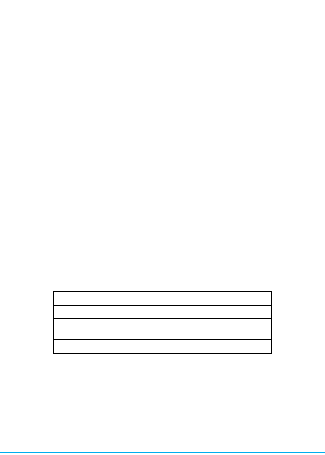
3UnpackthePRU.
aRemovethepowercableandanyothership-a-longitemsfromeithersideofthePRU.
bConnectahoisttothetwoDringsatthetopofthePRU.
Top of a
Dual-Bay PRU
D-Rings on
the PRU
FlexWave Prism Remote Unit and HDM RF Module Installation Guide 320000117795 Rev A • FWPP-501-01 Issue 1
Page 40 © March 2016 CommScope, Inc.
Install the Prism Remote Unit
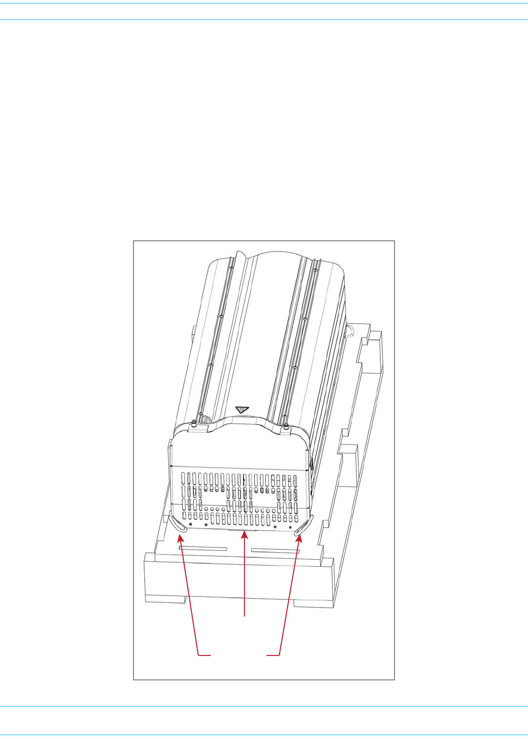
cLoosenthetwocaptivescrewsatthebottomofthePRU.
BoƩom of the PRU
CapƟve screws on the PRU
FWPP-501-01 Issue 1 • 320000117795 Rev A FlexWave Prism Remote Unit and HDM RF Module Installation Guide
© March 2016 CommScope, Inc. Page 41
Install the Prism Remote Unit
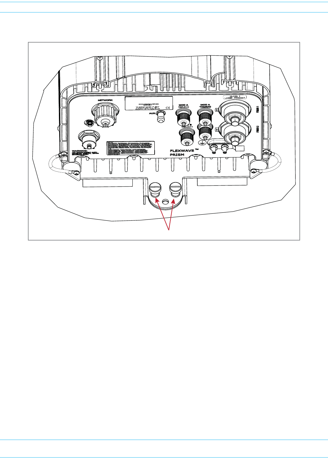
dHoistthePRUtoan
uprightpositionandtap
thecratedownwardsto
separatethePRUfromthe
MountingBracket.
eRemovetheMounting
Bracketfromthecrate:
iUnscrewtwoboltsand
removetheMounting
Bracketfromthecrate.
ii SavetheMounting
Bracketforfield
installation.
iii Savethetwoboltsand
emptyshippingcrate
foruseshouldthe
equipmentrequire
shipment.
CAUTION! The crate used to ship
the Fullband Remote
Unit and the two bolts
used to fasten the
Mounting Bracket to
the shipping crate are
not intended for use
for when mounting
the PRU in the field.
Hoist should be connected
to the two D-Rings on the
top of the PRU chassis
Tap the crate down as you
hoist the PRU chassis up
MounƟng bracket will sƟll
be aƩached to the crate

FlexWave Prism Remote Unit and HDM RF Module Installation Guide 320000117795 Rev A • FWPP-501-01 Issue 1
Page 42 © March 2016 CommScope, Inc.
Install the Prism Remote Unit
MOUNT THE PRISM REMOTE UNIT
ThePRUmaybeattachedtoautilitypole,amast,oronasolidflatsurface.Installationconsistsof
securingthebrackettothemountingsurfaceandthenhangingthePRUfromthebracket.Thebracket
maybeattachedtoavarietyofsurfacessuchaswood,concrete,orsteel.
ThisguideprovidestheinformationyouneedtoinstallandusetheFlexWavePrismRemoteMounting
Kit.
Toensureasafeinstallation,followthestepsinthisdocumentinthefollowingorder:
1Gatherrequiredtoolsandsuppliesasdescribedin"InstallationToolsandSupplies”onpage36.
2Followtheguidelinesin"MountingPlans”onpage30todecidethebestplacetoinstallandmount
thePRU.
3Familiarizeyourselfwiththe"MountingCautions”onpage42.
Mounting Cautions
ObservethefollowingcautionswheninstallingtheMountingBracketandwhenhangingaPRUonthe
bracket.
CAUTION! Use appropriate lifting equipment when unpacking, moving or installing the Prism Remote
Unit. Do not stand under the Prism Remote Unit as it is being hoisted into position for
installation. A failure of the lifting equipment could result in serious personal injury.
CAUTION! The pole must be structurally sound and able to support the weight of the unit being installed
as listed in Table 19 on page 31.
CAUTION! The hardware used to package the PRU for shipment is not intended for Prism Remote Unit
installations and should be kept with the Prism Remote Unit packaging. Do not use the
shipping hardware when mounting a Prism Remote Unit.
Mounting Methods
Fourinstallationmethodsareprovided,proceedtothecorrectprocedureforyourinstallation
environment:
•"SteelPoleInstallationUsingSteelBanding”onpage43
•"PoleMountInstallationUsingBolts”onpage46
•"Wood-FramedWallMountingProcedure”onpage47
•"MasonryWallMounting”onpage49
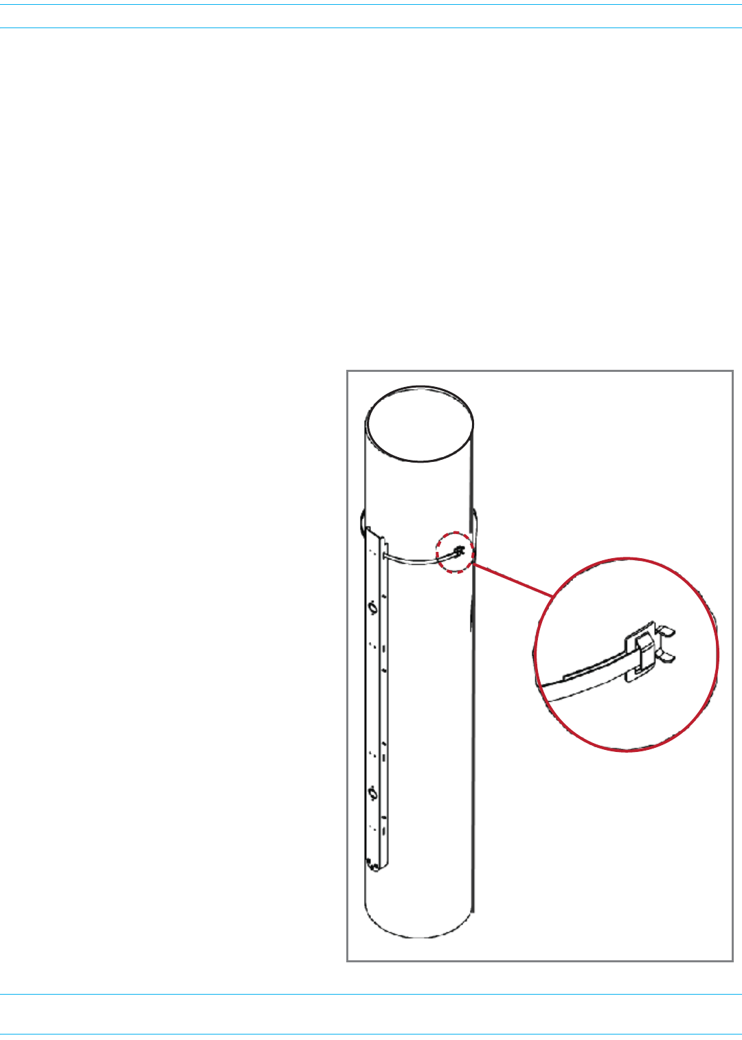
FWPP-501-01 Issue 1 • 320000117795 Rev A FlexWave Prism Remote Unit and HDM RF Module Installation Guide
© March 2016 CommScope, Inc. Page 43
Install the Prism Remote Unit
Steel Pole Installation Using Steel Banding
CAUTION! Always wear safety goggles when working with metal banding and when using tensioning
tools.
CAUTION! This section describes how to secure a PRU to a steel pole using steel bands. In high
earthquake risk areas, CommScope advises in addition to banding, bolts should be used
redundantly to ensure mechanical mounting capable of surviving severe seismic activity.
Typical areas where this attachment method are suggested are Earthquake Risk Zone 4, per
Bellcore GR-63-CORE, section 4.4.1.1. If you have application specific questions, consult the
Wireless Technical Assistance Center (TAC) for technical assistance (see "DCCS Global
Technical Support” on page 119). For information on bolting, see "Pole Mount Installation
Using Bolts” on page 46.
Stainless-steelbandsareusedtosecuretheMountingBrackettoametalpoleormastthatcannotbe
piercedwithascreworbolt.Thenumberofbandstobeusedisdependentontheconfigurationofthe
PRUasdescribedinTable20onpage36.
1Referto"MountingCautions”onpage42
beforebeginningthisprocess.
2LocatetheMountingBracketprovided
withthePRUMountingKitandobtain
thetoolsandsupplieslistedin"Tools
RequiredforAllMountingMethods”on
page36and"AdditionalToolsand
SuppliesRequiredforSteel-Pole
Mounting”onpage36.
3Slideabuckleonthebandandsecureby
doublingoverunderbuckle,asshownin
theillustrationtotheright,oras
instructedinmanufacturer's
instructions.
CAUTION! The pole must have a
diameter of at least
6 inches.
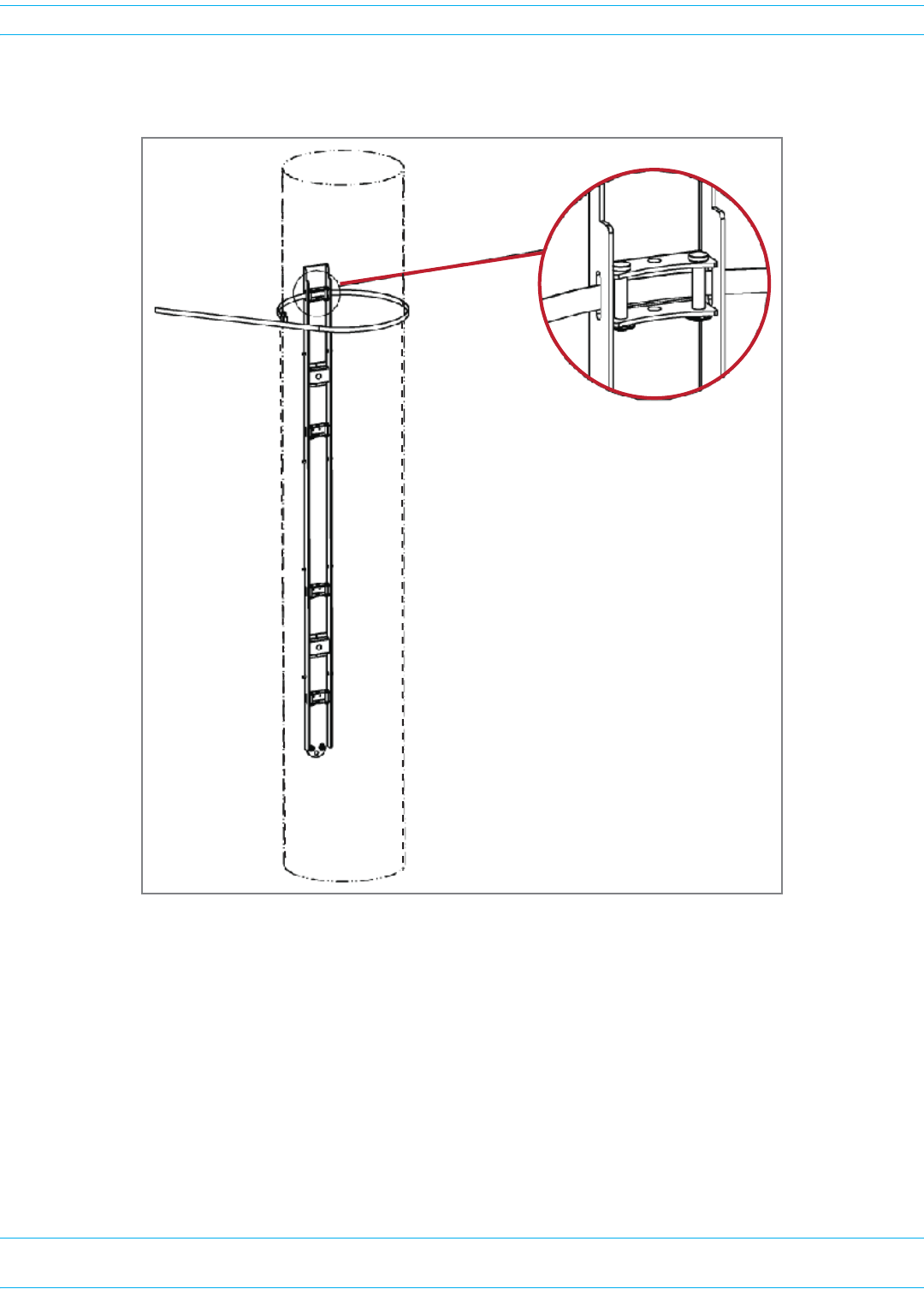
FlexWave Prism Remote Unit and HDM RF Module Installation Guide 320000117795 Rev A • FWPP-501-01 Issue 1
Page 44 © March 2016 CommScope, Inc.
Install the Prism Remote Unit
BandsshouldpassthrougheachslotoftheMountingBracket,fromtoptobottom,ensuringtheband
passesoverthetopofthepins,asshownbelow,andagainthroughthebuckle.
4Wrapthebandaroundpoleoncemore,passingthroughtheslotsintheMountingBracketandover
pins,andagainthroughbuckle.Doublebandingiscriticaltogeneratemaximumradialcompression
ofbandingtopoleandMountingBracket.
5Followspecificmanufacturer'sinstructionsfortensioningbandstorecommendedlevels.
6Rolltoolover,bendingbandoveritselfatexitfromthebuckle,asshownabove,orasinstructedin
themanufacturer'sinstructionstotemporarilysecuretensionedband.
7Cutbandusingtensioningtoolasinstructedinthemanufacturer'sinstructions.
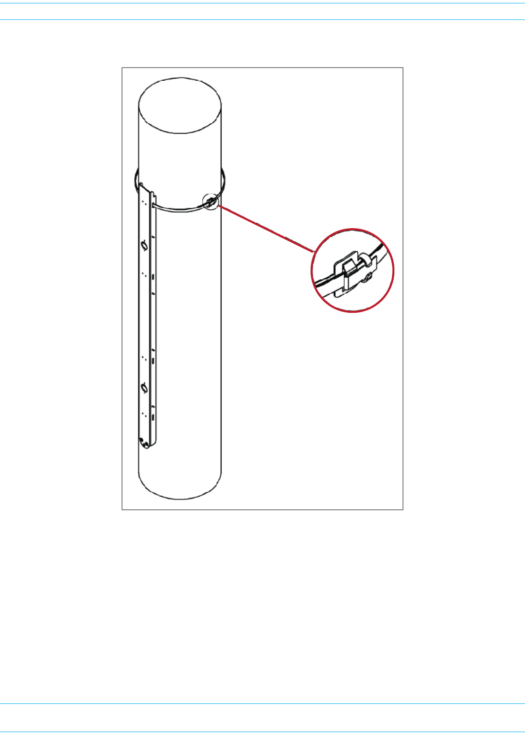
FWPP-501-01 Issue 1 • 320000117795 Rev A FlexWave Prism Remote Unit and HDM RF Module Installation Guide
© March 2016 CommScope, Inc. Page 45
Install the Prism Remote Unit
8Clinchbandstubinplacebyhammeringdownbuckleears,asshownbelow.
9RepeatStep3onpage43throughStep8foreachremainingbandingslotoftheMountingBracket.
10 HangthePRUfromtheMountingBracketasshownin"InstallingaPRUontheMountingBracket”on
page51.
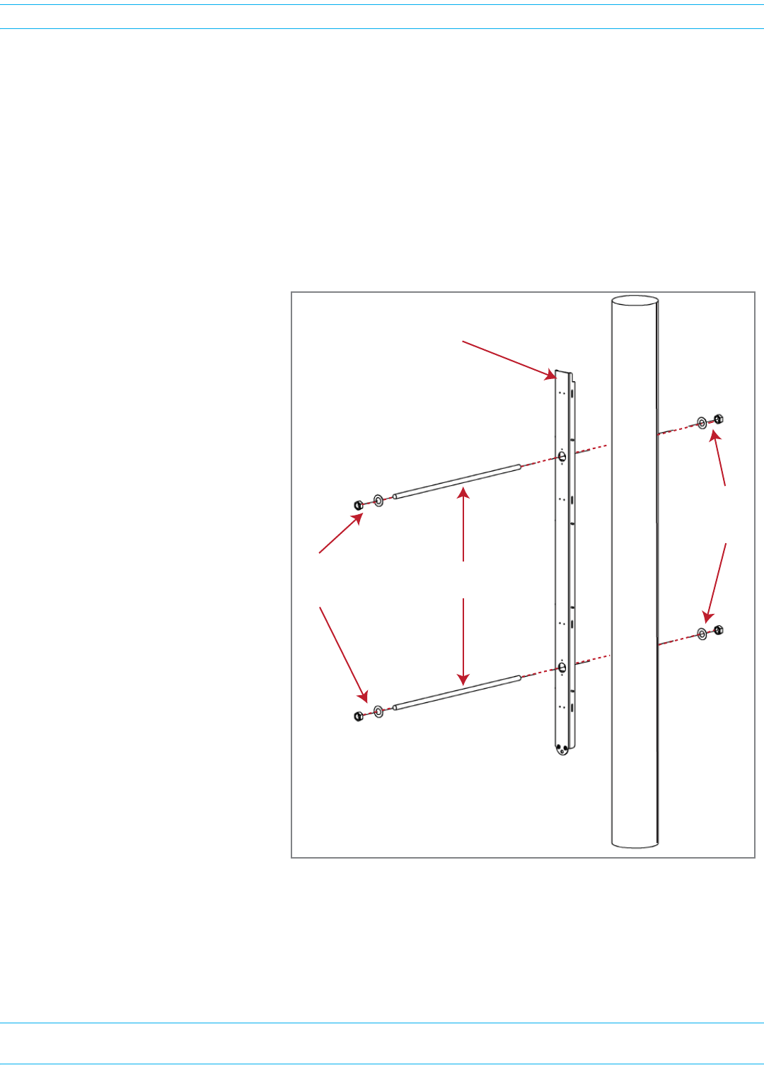
FlexWave Prism Remote Unit and HDM RF Module Installation Guide 320000117795 Rev A • FWPP-501-01 Issue 1
Page 46 © March 2016 CommScope, Inc.
Install the Prism Remote Unit
Pole Mount Installation Using Bolts
CAUTION! This section describes how to secure a PRU to a wood pole using bolts. In high earthquake risk
areas, CommScope advises in addition to bolting, banding should be used redundantly to
ensure mechanical mounting capable of surviving severe seismic activity. Typical areas where
this attachment method are suggested are Earthquake Risk Zone 4, per Bellcore GR-63-CORE,
section 4.4.1.1. If you have application specific questions, consult the Wireless Technical
Assistance Center (TAC) for technical assistance (see "DCCS Global Technical Support” on
page 119). For information on banding, see "Steel Pole Installation Using Steel Banding” on
page 43.
1Referto"MountingCautions”onpage42beforebeginningthisprocess.
2LocatetheMountingBracket
providedwiththePRU
MountingKitandobtainthe
toolsandsupplieslistedin
"ToolsRequiredforAll
MountingMethods”onpage36
and"AdditionalToolsand
SuppliesRequiredfor
Wood-PoleMounting”on
page37.
3EstablishwheretheMounting
Bracketwillbemountedonthe
poleandthendeterminethe
locationofthebracket
mountingboltsonthepoleand
markholelocationsonpole.
4Drilla1/2-inchhole(equalto
diameterofthrough-bolt)into
theutilitypoleatthepoints
markedinStep3.
5Securethebrackettotheutility
poleusingtwothrough-bolts,
washers,andnutsasshownin
thefollowingillustration,and
thentightenthenutssecurely.
6Followthestepsin"Installinga
PRUontheMountingBracket”
onpage51.
Pole-mounƟng
bracket
Through-bolts
Nuts
and
washers
Nuts
and
washers
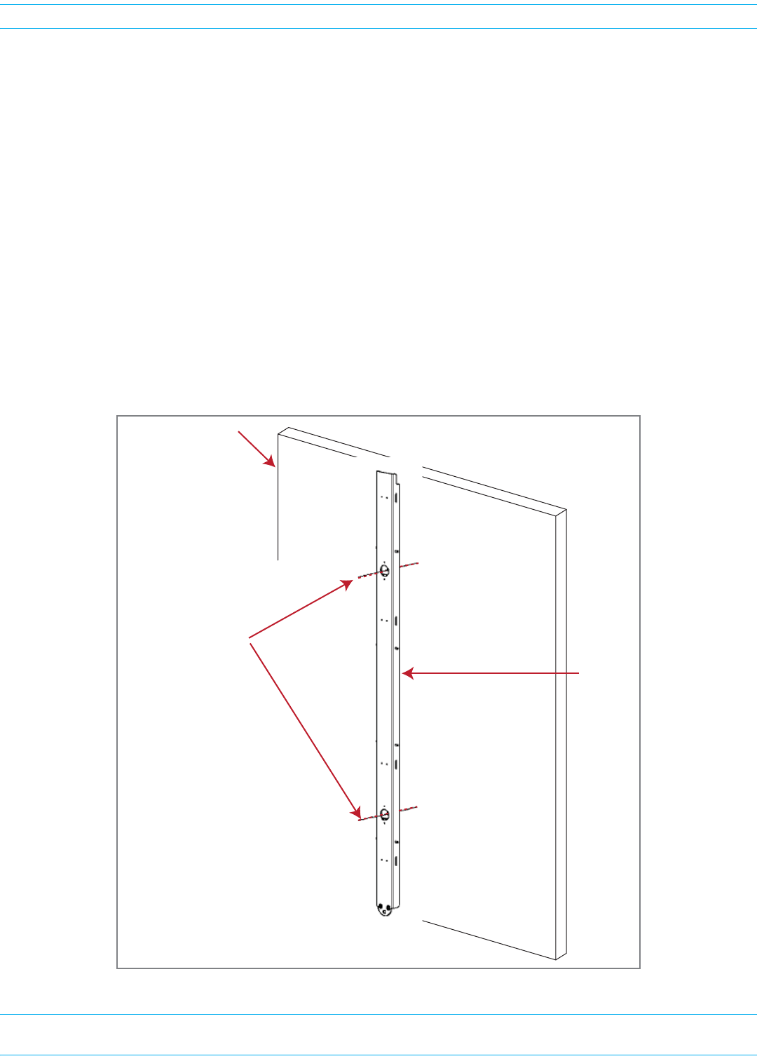
FWPP-501-01 Issue 1 • 320000117795 Rev A FlexWave Prism Remote Unit and HDM RF Module Installation Guide
© March 2016 CommScope, Inc. Page 47
Install the Prism Remote Unit
Wood-Framed Wall Mounting Procedure
1Referto"MountingCautions”onpage42beforebeginningthisprocess.
2LocatetheMountingBracketprovidedwiththePRUMountingKit.
3Obtainthetoolsandsupplieslistedin"ToolsRequiredforAllMountingMethods”onpage36and
"AdditionalToolsandSuppliesRequiredforFlat-SurfaceMounting”onpage37.
4Obtainplywoodwithaminimumthicknessof0.75-inches(19.0cm)tobeusedasabackerboard.
CAUTION! If the PRU is installed in an area in which there may be moisture, use pressure-treated
plywood.
5Cutthepressure-treatedplywoodtothecorrectsizetoaccommodatethePRUbeinginstalled(see
dimensionsinTable19onpage31).
6Toavoidahazardouscondition,firmlysecurethebackerboardtotheinteriorframingofthewall.
7HoldtheMountingBracketuptothewallandmarkthelocationoftheMountingBracket’stwo
mountingholesontheplywoodbacker:
3/4-inch Plywood
Backer Board
(secure to wall studs)
MounƟng
Bracket
Mark the locaƟon
of the two mounƟng
holes
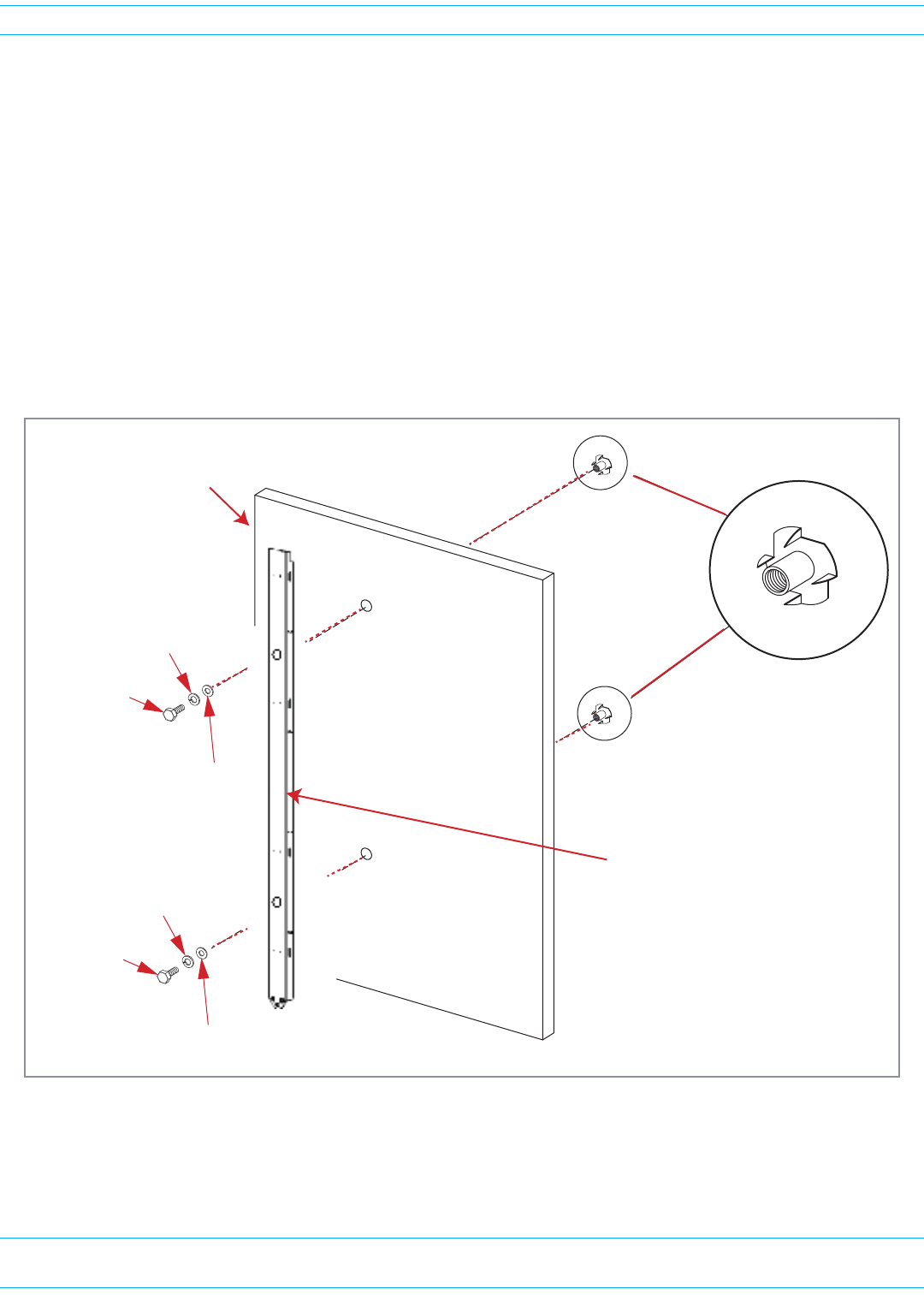
FlexWave Prism Remote Unit and HDM RF Module Installation Guide 320000117795 Rev A • FWPP-501-01 Issue 1
Page 48 © March 2016 CommScope, Inc.
Install the Prism Remote Unit
8Drill9/16-inchholesintheplywoodbackerattheholepositionsmarkedinStep7.
9Refertothefollowingfigureanddothefollowing:
aFromthesideofthebackerthatwillfacethewall,drivea1/2-inchTeeNutintoeachdrilledhole.
bMounttheplywoodbackeronthewallandfirmlysecureittothewall’sinteriorstuds.
cLocatethetwo1/2x1-inchhexboltsandplacea1/2-inchlockwasherand1/2–inchflatwasher
oneachboltandthensecuretheMountingBrackettotheplywoodbackerusingtheassembled
boltsandwashers.
CAUTION! If plywood backer board or supporting wall is not smooth or does not provide a flat mounting
plane for the PRU, add 1/2-inch flat washers between the Mounting Bracket and the
mounting surface as required to prevent the PRU from twisting or distorting when secured to
the mounting surface.
10 HangthePRUfromtheMountingBracketasshownin"InstallingaPRUontheMountingBracket”on
page51.
Tee Nut
3/4-inch Plywood
backer board
(secure to wall studs)
1/2 x 1-1/2-inch
Hex bolt
1/2-inch Flat
washer
1/2-inch Lock
washer
1/2 x 1-1/2-inch
Hex bolt
1/2-inch Flat
washer
1/2-inch Lock
washer
Prism Remote Unit
MounƟng Bracket
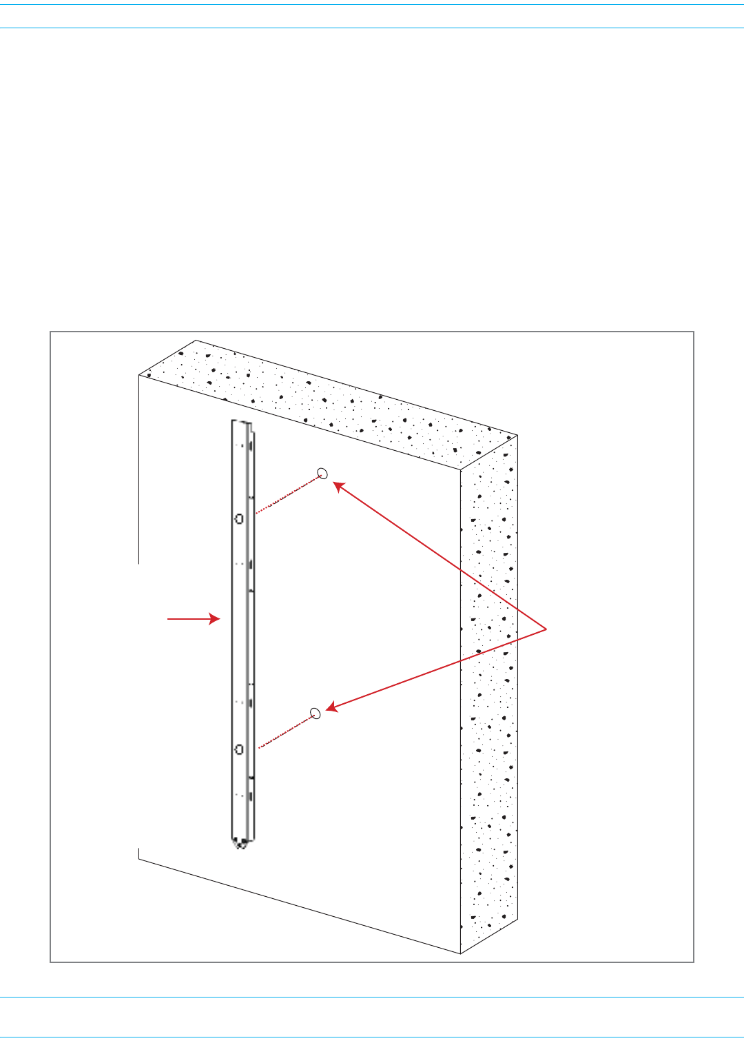
FWPP-501-01 Issue 1 • 320000117795 Rev A FlexWave Prism Remote Unit and HDM RF Module Installation Guide
© March 2016 CommScope, Inc. Page 49
Install the Prism Remote Unit
Masonry Wall Mounting
1Referto"MountingCautions”onpage42beforebeginningthisprocess.
2LocatetheMountingBracketprovidedwiththePRUMountingKit.
3Obtainthetoolsandsupplieslistedin"ToolsRequiredforAllMountingMethods”onpage36and
"AdditionalToolsandSuppliesRequiredforFlat-SurfaceMounting”onpage37.
4Verifythatconcreteanchorstobeusedaredesignedfor1/2-inchbolts.
5HoldtheMountingBracketinpositiononthewall.
6Usingapencil,markthelocationofeachoftheMountingBracket’stwomountingholesonthewall.
WhenmountingthePRUonamasonrysurface,locatethemountinganchorsascloseaspossibleto
thecenterofanybricksorblocks,especiallytheupperanchors.
Masonry Wall
Prism Remote Unit
MounƟng Bracket Mark the locaƟon of the
two mounƟng holes
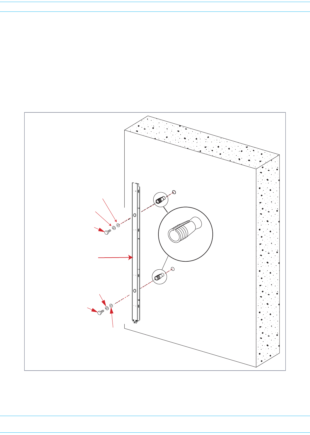
FlexWave Prism Remote Unit and HDM RF Module Installation Guide 320000117795 Rev A • FWPP-501-01 Issue 1
Page 50 © March 2016 CommScope, Inc.
Install the Prism Remote Unit
7Refertoanchormanufacturer'stechnicaldatatoensureproperdrilldiametertobeused,andthen
drillholesinthewallatthelocationsmarkedinStep6.
8Refertothefollowingfigureanddothefollowing:
aSettheanchorsinthewall.
bLocatethetwo1/2x1-1/2-inchmountingboltsandplacea1/2-inchlockwasherand1/2-inch
flatwasheroneachbolt.
cPlacetheMountingBracketoverthetwoanchors.Threada1/2x1-1/2-inchmountingbolt
(withinstalledwashers)intoeachoneoftheanchors.Tightenboltsuntilsecure.
9HangthePRUfromtheMountingBracketasshownin"InstallingaPRUontheMountingBracket”on
page51.
1/2-inch flat washer
Masonry Wall
1/2-inch Concrete
anchors
1/2 x 1-1/2-inch Hex bolt
1/2-inch Lock washer
MounƟng bracket
1/2 x 1-1/2-inch Hex bolt
1/2-inch flat washer
1/2-inch Lock washer
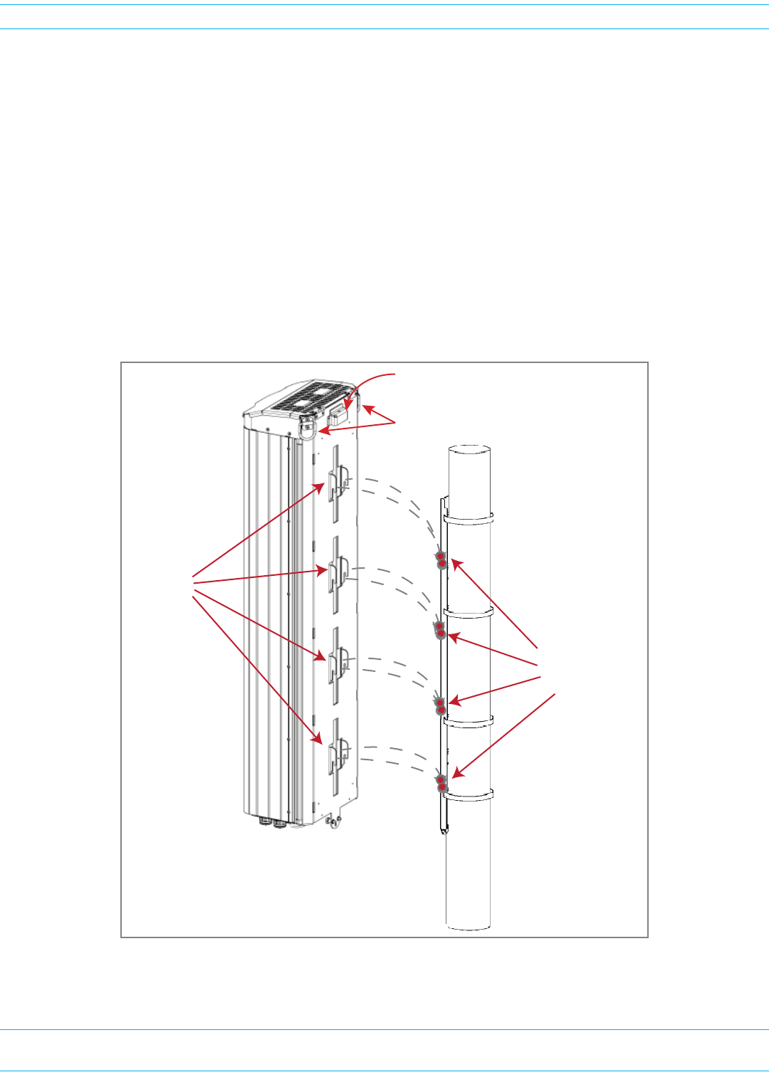
FWPP-501-01 Issue 1 • 320000117795 Rev A FlexWave Prism Remote Unit and HDM RF Module Installation Guide
© March 2016 CommScope, Inc. Page 51
Install the Prism Remote Unit
Installing a PRU on the Mounting Bracket
ThebasicproceduretohangaPRUonaMountingBracketisthesame.Theillustrationsinthis
procedure,however,showapole-mountinstallation.
1Referto"MountingCautions”onpage42beforebeginningthisprocess.
2UsetheD-RingsonthetopofthePRUtohoistthePRUintopositionforattachmenttotheMounting
Bracket.
CAUTION! To avoid damage to the PRU and to avoid personal injury, use appropriate lifting equipment.
3MatethemountinghooksonthebackofthePRUwiththe8horizontalhanging-bracketpinsonthe
MountingBracketasshownbelow.
4LowerthePRUuntiltheMountingCaponthetopofthePRUissnugagainstthetopoftheMounting
Bracket.
5Usetheflat-bladescrewdrivertosecurethetwocaptivefastenersonthebottomofthePRUtothe
MountingBracket.
MounƟng
hooks (8)
Hanging-Bracket
Pins (8)
D-Rings
MounƟng Cap
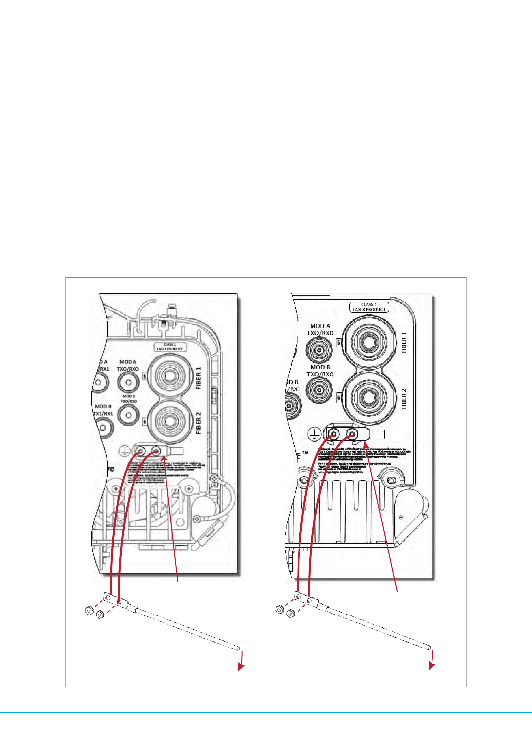
FlexWave Prism Remote Unit and HDM RF Module Installation Guide 320000117795 Rev A • FWPP-501-01 Issue 1
Page 52 © March 2016 CommScope, Inc.
Install the Prism Remote Unit
GROUND THE PRU CHASSIS
CAUTION! Avoid sharp bends in the ground wire.
CAUTION! For proper and safe equipment operation, use a #6 copper wire terminated with the provided
ring terminal to link the PRU to an earth-ground source.
1Locatea#6AWG(4mm)coppergroundingwirelongenoughtoreachanapprovedearthground.
2Useasocketwrenchwitha3/8-inchdeepsockettoremovethetwo10-32KepsNutsfromthe
Dual-GroundconnectoronthebottomofthePRU.
3Securetheringterminalendofthegroundingwiretothegroundstudsontheunitusingthetwo
10-32KepsNutsremovedinStep2,andthentorquethenutsto18in-lbs±1in-lb.
4Routethefreeendofthegroundingwiretoanapprovedearthgroundsource.
5Cutthegroundwiretolengthandconnectittotheearthgroundsourceasspecifiedbylocalcodeor
practice.
To Earth Ground
Ground wire
10-32
Keps Nuts
AC-Powered PRU
Dual-Ground
connector
To Earth Ground
Ground wire
10-32
Keps Nuts
DC-Powered PRU
Dual-Ground
connector
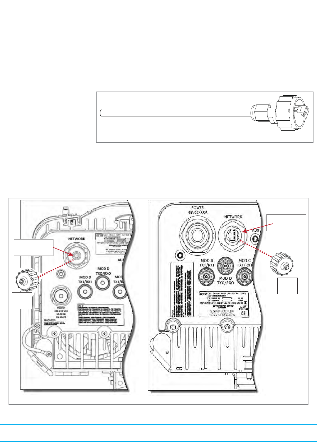
FWPP-501-01 Issue 1 • 320000117795 Rev A FlexWave Prism Remote Unit and HDM RF Module Installation Guide
© March 2016 CommScope, Inc. Page 53
Install the Prism Remote Unit
CONNECT A NETWORK CABLE TO THE PRU CHASSIS
ThePRUprovidesaNetworkportthatallowscommunicationswiththeinternalprocessorandaccess
totheHostLANnetwork.Thatis,thisprovidesaLANextensiontotheHostnetwork.TheNetworkport
is10/100/1000BASE-T/TX(802.3abcompliant)MDIandrequiresaminimumofCAT5cable.
NOTE: Although the interface might provide GigE, only 100 Mbps is provided for bandwidth between
the Host and Remote.
Thenetworkcablemust
beterminatedwitha
hardenedRJ-45male
connectorforconnection
totheNetworkport,as
showninthegraphicto
theright.Themaximum
cablelengthis300feet
(91.4m).
UsethefollowingproceduretoinstalltheNetworkcable:
1RemovethedustcapfromtheRJ-45connectorlocatedatthebottomofthePRU.
Network cable terminated with a hardened RJ-45 male connector
RJ-45 Network
connector
AC-Powered PRU DC-Powered PRU
RJ-45 Network
connector
Dust
cap
Dust
cap
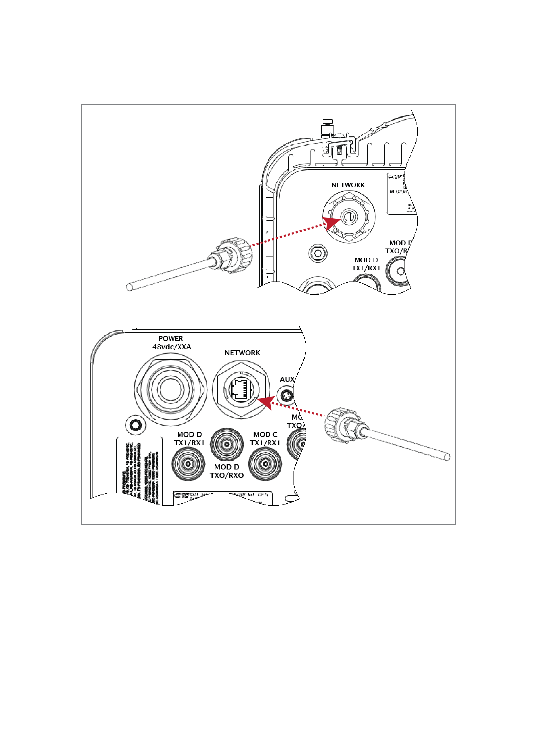
FlexWave Prism Remote Unit and HDM RF Module Installation Guide 320000117795 Rev A • FWPP-501-01 Issue 1
Page 54 © March 2016 CommScope, Inc.
Install the Prism Remote Unit
2RoutethenetworkcablefromthenetworkconnectiontotheundersideofthePRU.
3AligntheplugendoftheRJ-45cableconnectorwiththeRJ-45portreceptacleandtheninsertthe
cableplugintotheportreceptacle.
4Slidetheconnectornutuptotheportuntilitengagestheconnectorlockingmechanism.
5Tightentheconnectornutinaclockwisedirection(ifnecessary,useawrenchtogriptheconnector
nut)untilitsnapspasttheindentedpositionandlocksintoplace.Itmaybenecessarytoapply30to
50in-lbs(3.4to5.6Nm)oftorquetotheconnectornutinordertoturnitpasttheindentedposition.
DC-Powered PRU
AC-Powered PRU
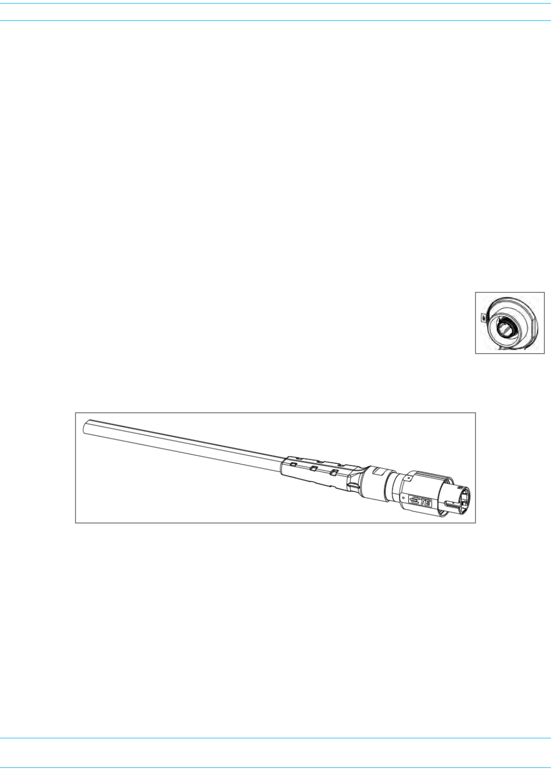
FWPP-501-01 Issue 1 • 320000117795 Rev A FlexWave Prism Remote Unit and HDM RF Module Installation Guide
© March 2016 CommScope, Inc. Page 55
Install the Prism Remote Unit
CONNECT FIBER CABLE TO THE PRU CHASSIS
TherearethreefiberconnectoroptionsforthePrismRemoteUnit;followthefibercableinstallation
processthatisappropriatefortheconfigurationofthePRUthatyouareinstalling:
•"OptionA:HardenedMulti-FiberOpticConnector”onpage55
•"OptionB:FiberPass-ThroughConnector”onpage61
•"OptionC:ProAxConnector(LegacyAC-PoweredPRUs)”onpage65.
Option A: Hardened Multi-Fiber Optic Connector
NOTE: Use the following procedure to install the fiber cables using a Hardened Multi-Fiber Optic
Connector. If the PRU that you are installing has a Fiber Pass-Through Connector, follow the
procedure in "Option B: Fiber Pass-Through Connector” on page 61. If the PRU that you are
installing has a legacy ProAx Connector, follow the procedure in "Option C: ProAx Connector
(Legacy AC-Powered PRUs)” on page 65.
PRUsnowhaveaHardenedMulti-FiberOpticConnector(HMFOC),asshowninthe
pictureattheright.
AllPRUswiththeHMFOCconfigurationrequirethepurchaseofaMulti-FiberOptic
Cable,suchastheoneshownbelow,whichallowsthePRUtointerfacewiththeOSPfiber.
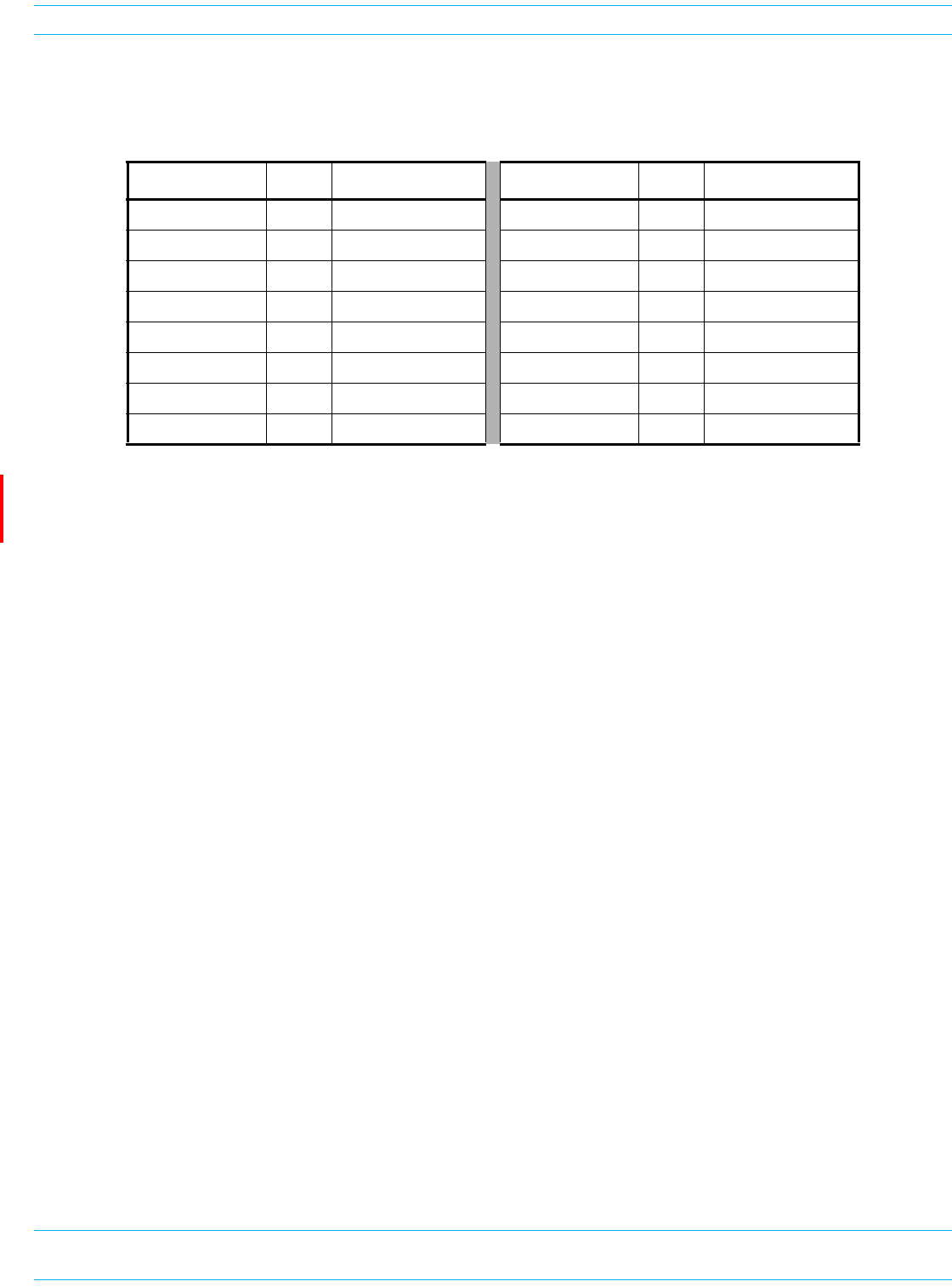
FlexWave Prism Remote Unit and HDM RF Module Installation Guide 320000117795 Rev A • FWPP-501-01 Issue 1
Page 56 © March 2016 CommScope, Inc.
Install the Prism Remote Unit
Table21identifieshowthefibersintheMulti-FiberOpticCablecorrelatetotheSeRFSFPs,whichcome
pre-wiredfromthefactory.
NOTE: Each SFP utilizes a single fiber optic pair. Each SFP can support up to 12 timeslots with up to
75 MHz of bandwidth. Each fiber connector on the FRU contains 4 fiber pairs, supporting the
use of 4 SFPs. If additional SFPs are necessary, use the second fiber connector (FIBER 2).
Table 21. Multi-Fiber Optic Cable Color Codes
Fiber Connector # Color SeRF SFP Connector Fiber Connector # Color SeRF SFP Connector
1Blue1 TX 2Blue5 TX
1Orange1 RX 2Orange5 RX
1 Green 2 TX 2 Green 6 TX
1Brown2 RX 2 Brown 6 RX
1Gray3 TX 2Gray7 TX
1White3 RX 2 White 7 RX
1Red4 TX 2Red8 TX
1Black4 RX 2 Black 8 RX
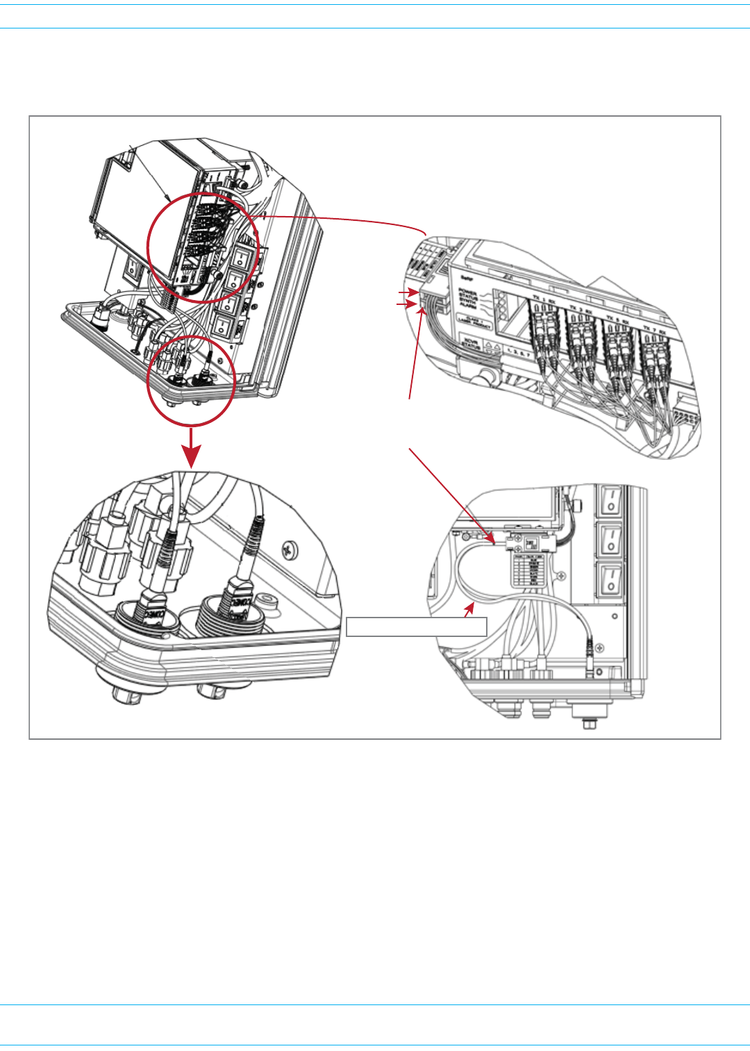
FWPP-501-01 Issue 1 • 320000117795 Rev A FlexWave Prism Remote Unit and HDM RF Module Installation Guide
© March 2016 CommScope, Inc. Page 57
Install the Prism Remote Unit
Figure13illustrateshowtheMulti-FiberOpticCablesusedwithHMFOCconnectorsrunbetweenthe
Fiber1andFiber2connectorsandtheSFPs.
Figure 13. Multi-Fiber Optic Cabling
Fiber 1 and Fiber 2 Connectors
(boƩom of PRU)
Fiber-opƟc cable runs
between the Fiber 1 and Fiber 2
Connectors and the SFPs
Fiber 1 assembly
Fiber 2 assembly
Fiber 1 and Fiber 2 cable
Fiber 1 Connector
(boƩom of PRU)
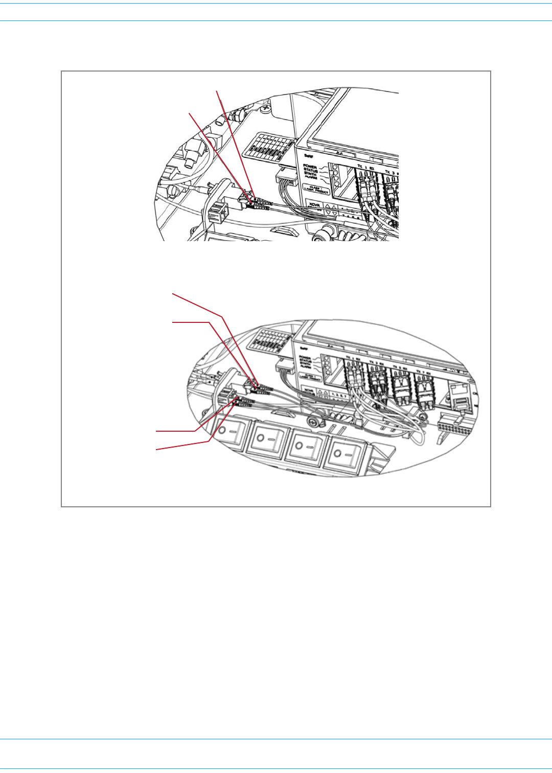
FlexWave Prism Remote Unit and HDM RF Module Installation Guide 320000117795 Rev A • FWPP-501-01 Issue 1
Page 58 © March 2016 CommScope, Inc.
Install the Prism Remote Unit
Figure14showsthecablingrequirementsforSingle-andDual-WDMunits.
Figure 14. Multi-Fiber Optic Cabling for Single- and Dual- WDM Units
1 RX - Orange
1 TX - Blue
Single-WDM HMFOC Units
1 RX - Orange
2 RX - Brown
WDM 1 Connector 1
1 TX - Blue
2 TX - Green
WDM 2 Connector 1
Dual-WDM HMFOC Units
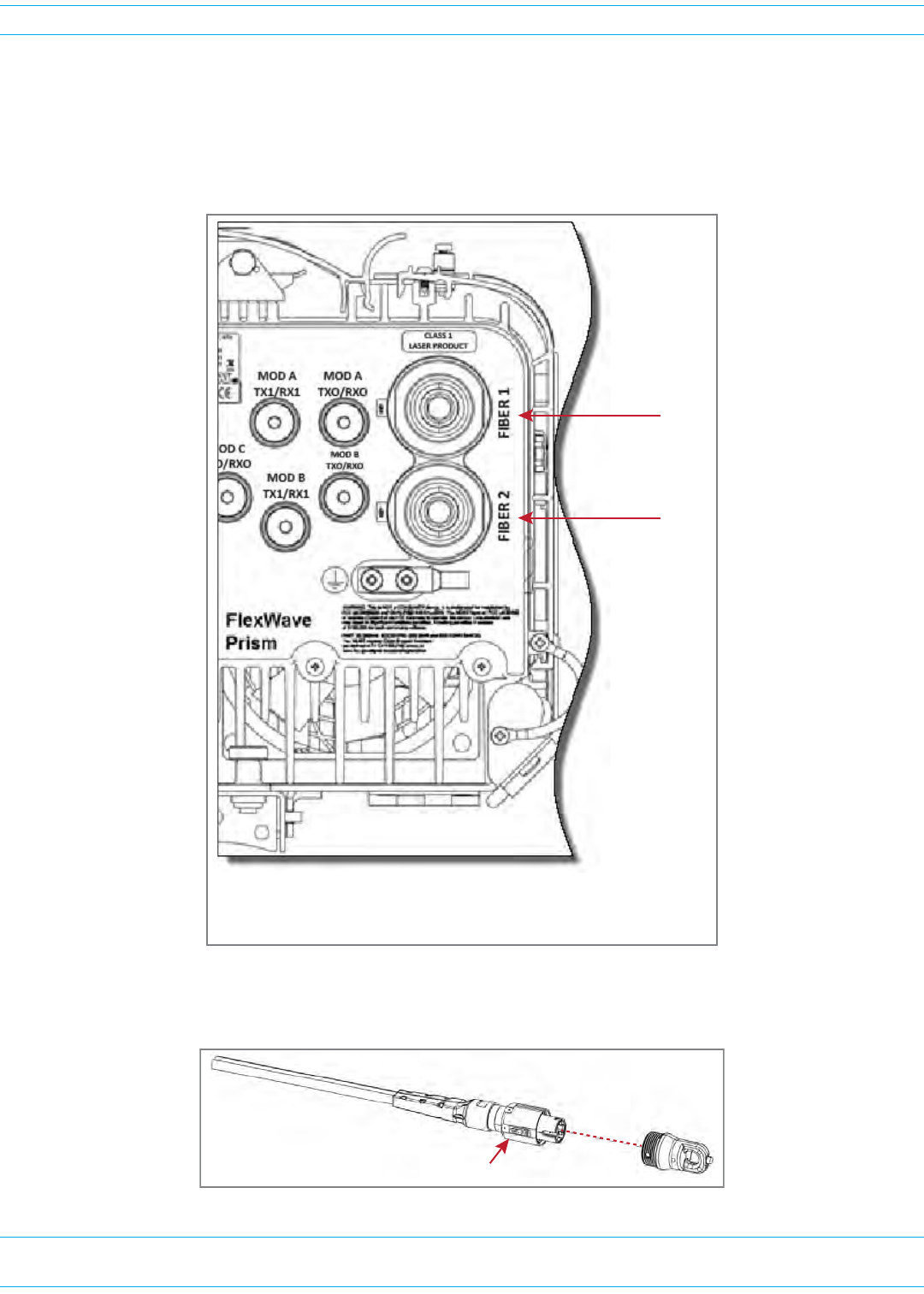
FWPP-501-01 Issue 1 • 320000117795 Rev A FlexWave Prism Remote Unit and HDM RF Module Installation Guide
© March 2016 CommScope, Inc. Page 59
Install the Prism Remote Unit
UsethefollowingproceduretoinstallthefibercablesusingtheHMFOC.
1Usea7/16”wrenchorsockettoremovethedust-covercapfromtheFiber1connector,locatedat
thebottomofthePRU.Youneedtoturnthecapcounter-clockwiseforseveralturns.
NOTE: Do not remove the dust cover from the Fiber 2 connector until directed to do so.
2RotatethecouplingnutoftheMulti-FiberOpticcablecounter-clockwisetoremoveitsdust-cover
cap.
AC or DC PRU
Fiber 1
Fiber 2
(The Fiber 1 and Fiber 2 connectors are in the same
locaƟon for both the AC- and DC-powered PRUs.)
Coupling nut
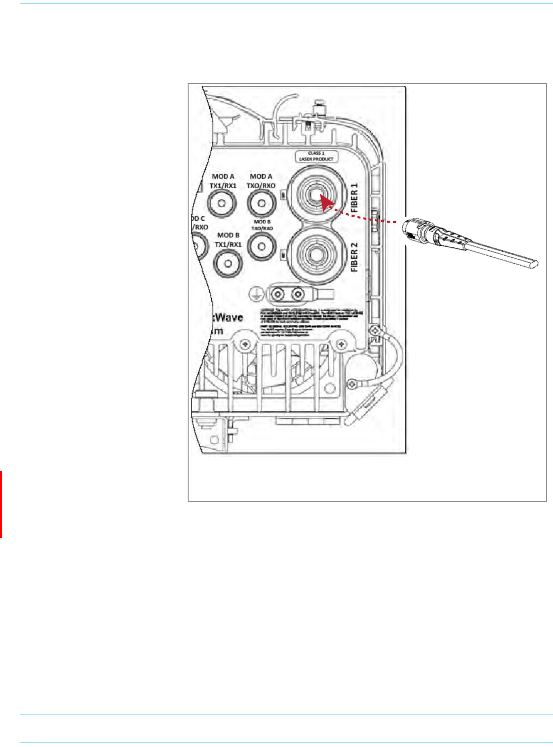
FlexWave Prism Remote Unit and HDM RF Module Installation Guide 320000117795 Rev A • FWPP-501-01 Issue 1
Page 60 © March 2016 CommScope, Inc.
Install the Prism Remote Unit
3CleantheMulti-FiberOpticcableconnectorusingindustryapprovedcleaningprocedures.
4CleantheFiber1portusingindustryapprovedcleaningprocedure.
5InserttheMulti-Fiber
Opticcableintothe
FIBER1connector;
refertothe
introductorymaterial
forthissectionfor
informationoncabling
requirements.
aAligntheplugendof
thecablewiththe
keyasindicatedon
theoverlayforthe
FIBER1connector,
asshownbelow.
bUsea9/16”wrench
torotatethe
couplingnut
clockwise;tightento
2-4in-lbs.
6RoutetheMulti-Fiber
Opticcablefromthe
undersideofthePRUto
theOSPbox.
7Securefibercablein
placefollowinglocal
practices.
8Ifnecessary,complete
Step1throughStep7to
addasecond
Multi-FiberOpticcable
totheFIBER2connector.
9Continueto"ConnecttheAntennaCable”onpage69.
MulƟ-fiber opƟc cable
AC or DC PRU
(The Fiber 1 and Fiber 2 connectors are in the same
locaƟon for both the AC- and DC-powered PRUs.)