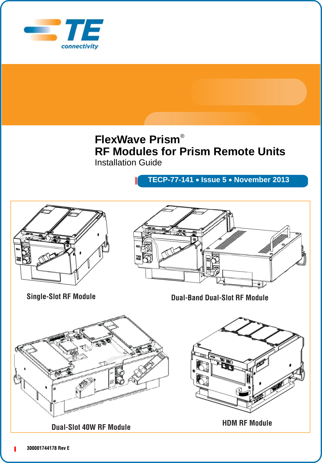
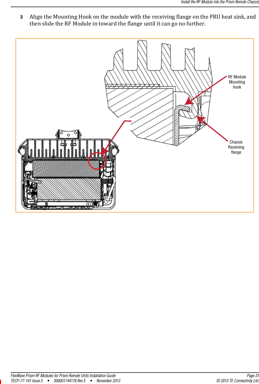
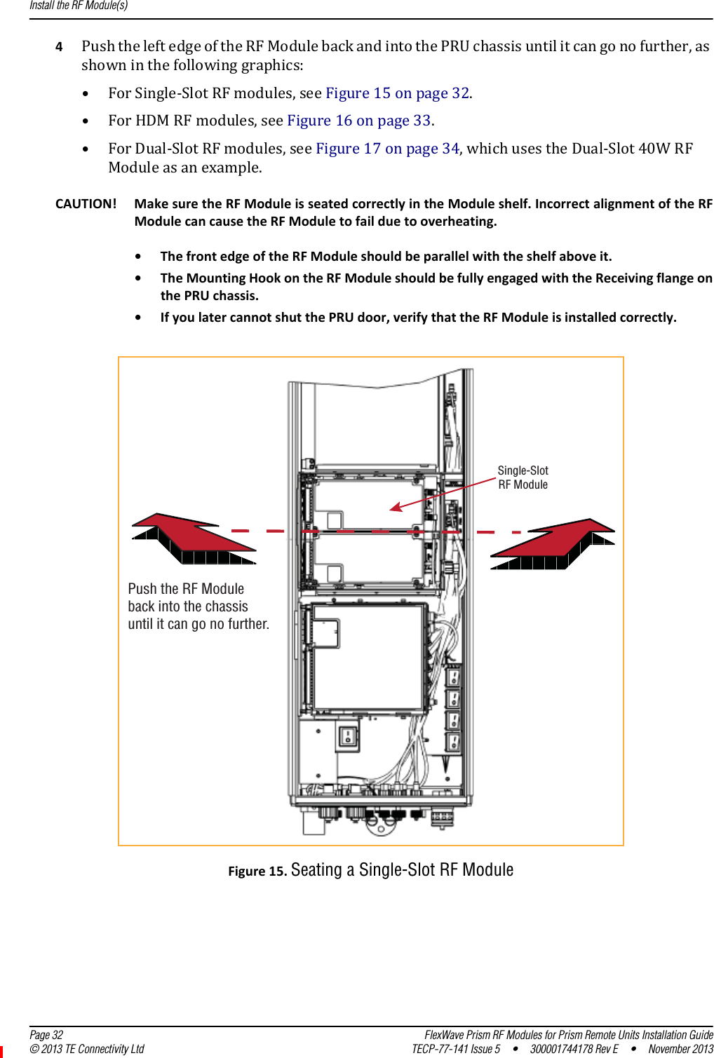
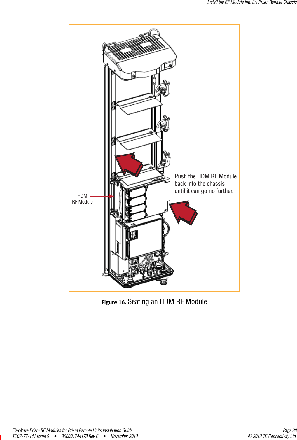
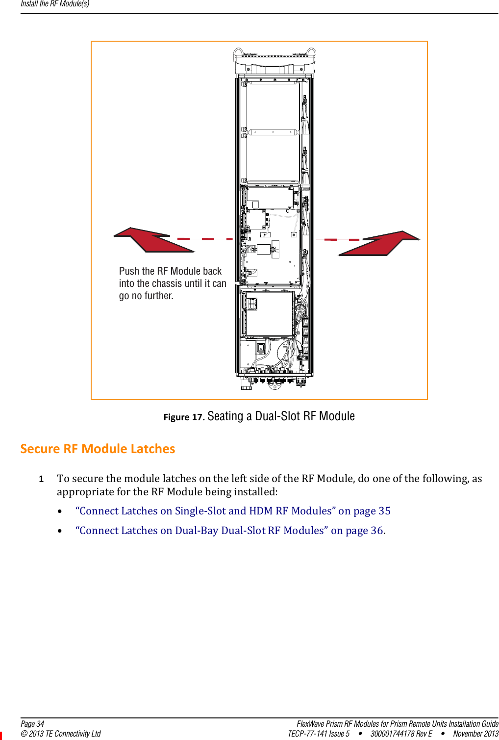
ADC Telecommunications PSM7A7UD FlexWave Prism HDM 700 Lower ABC/Upper C User Manual RF modules installation guide
ADC Telecommunications Inc FlexWave Prism HDM 700 Lower ABC/Upper C RF modules installation guide
UserManual.wiki
>
ADC Telecommunications
>
PSM7A7UD User Manual
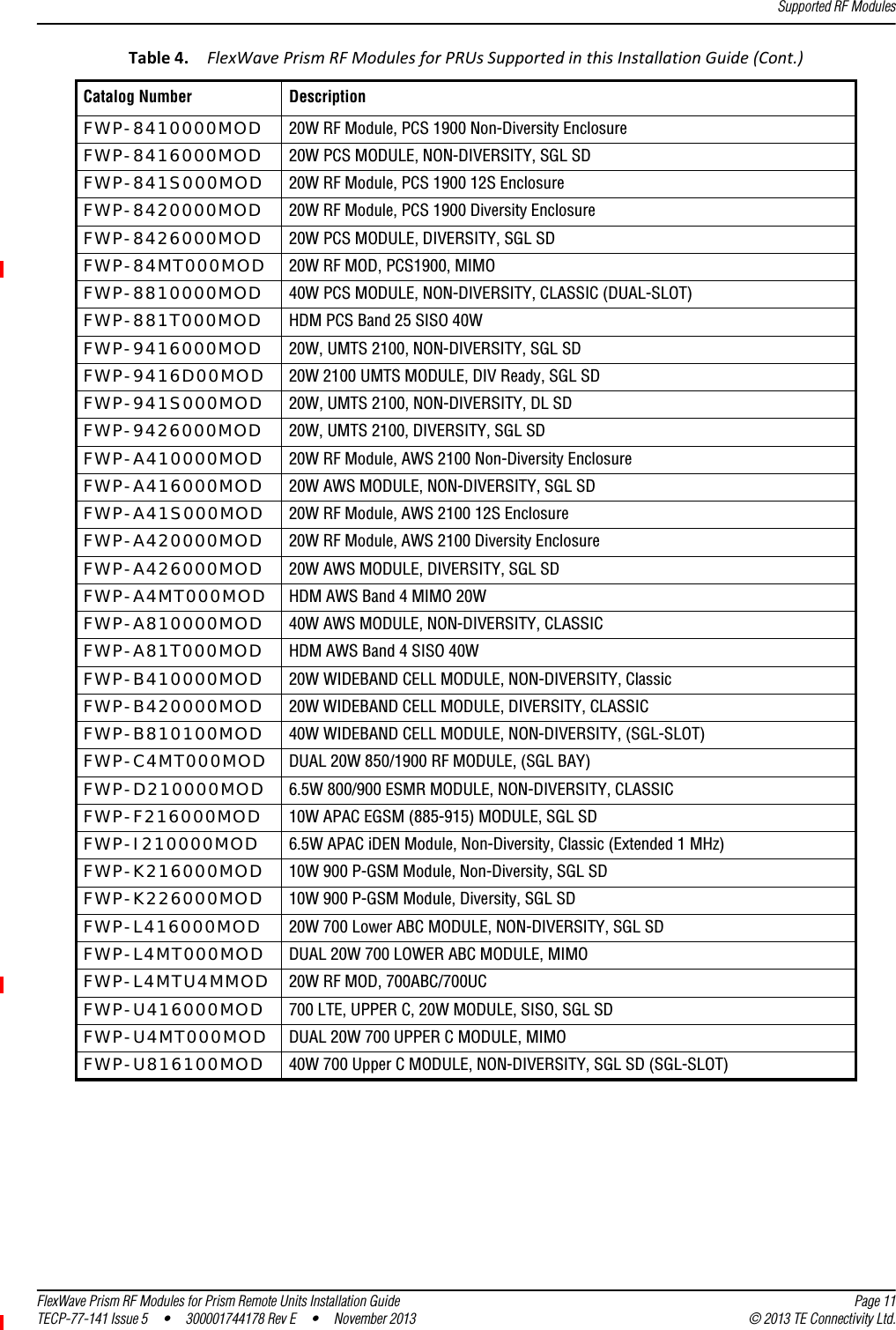
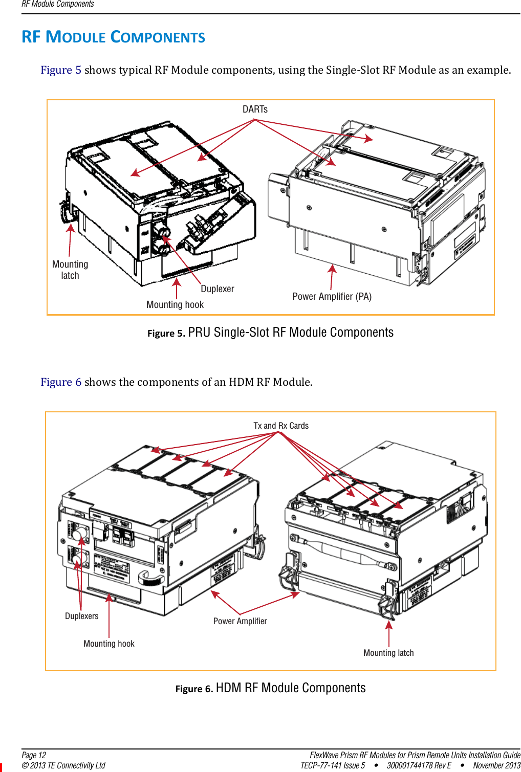
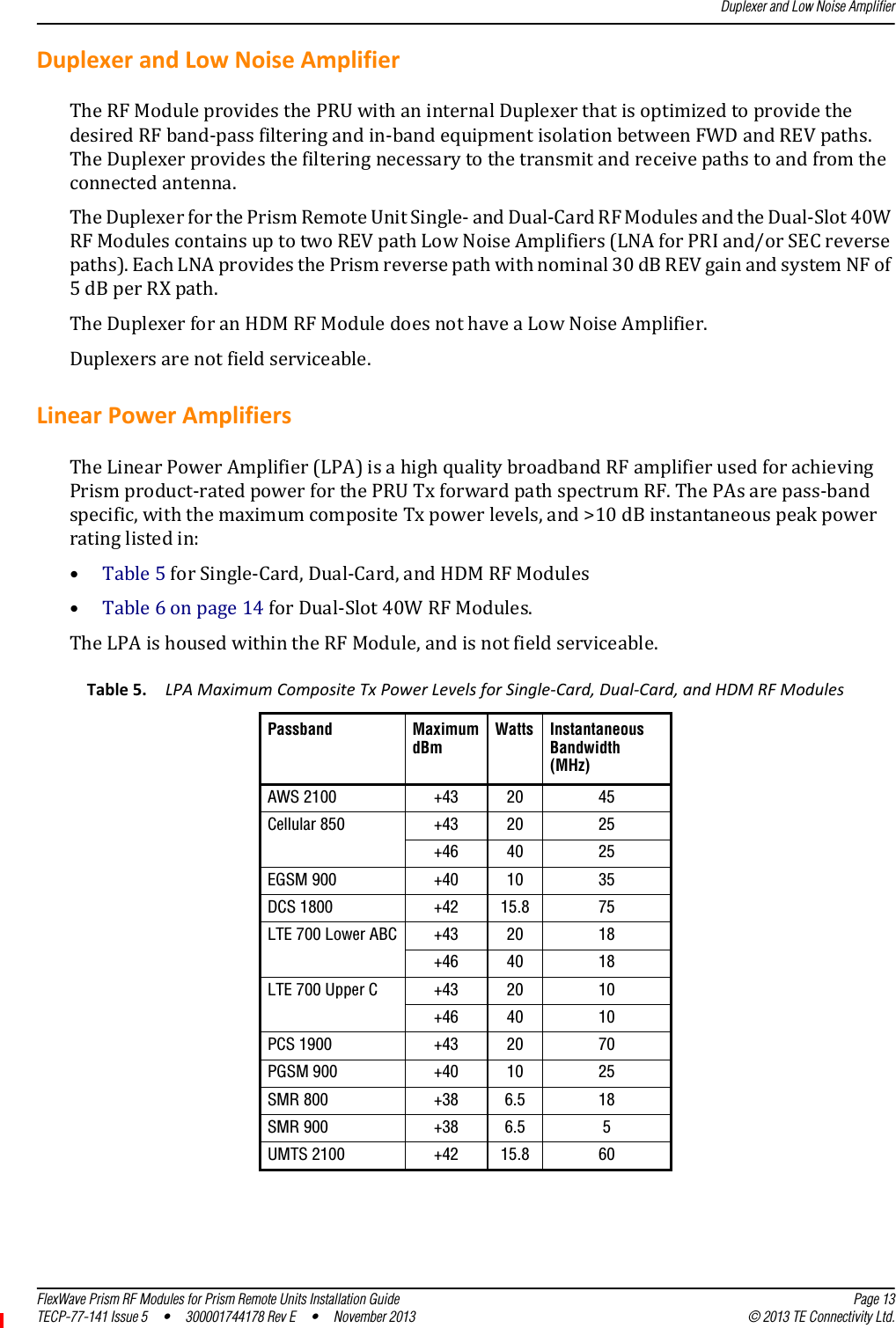
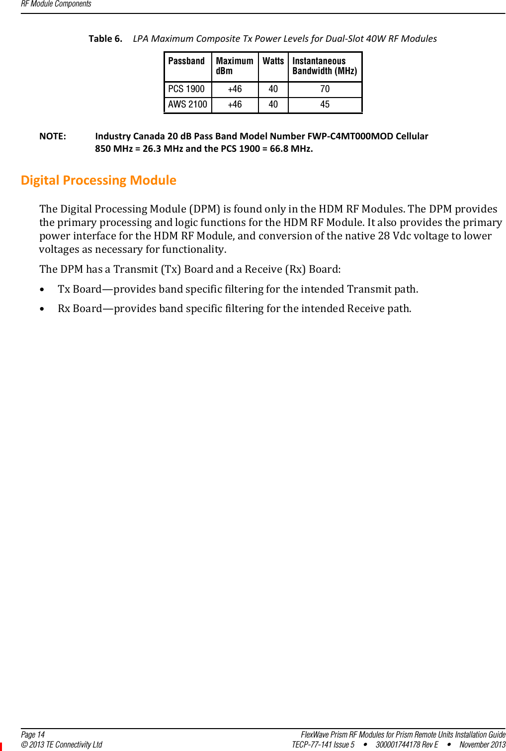
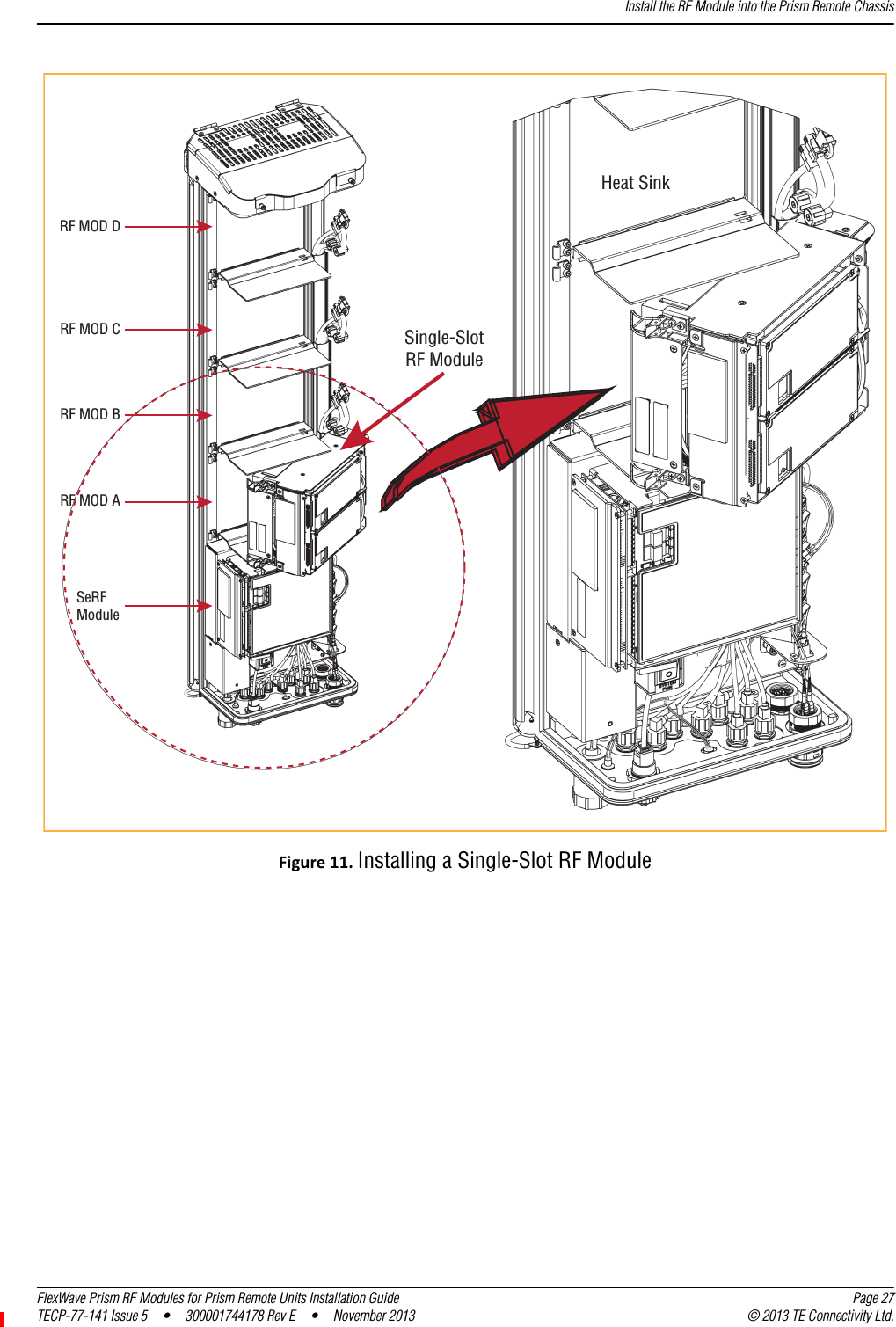
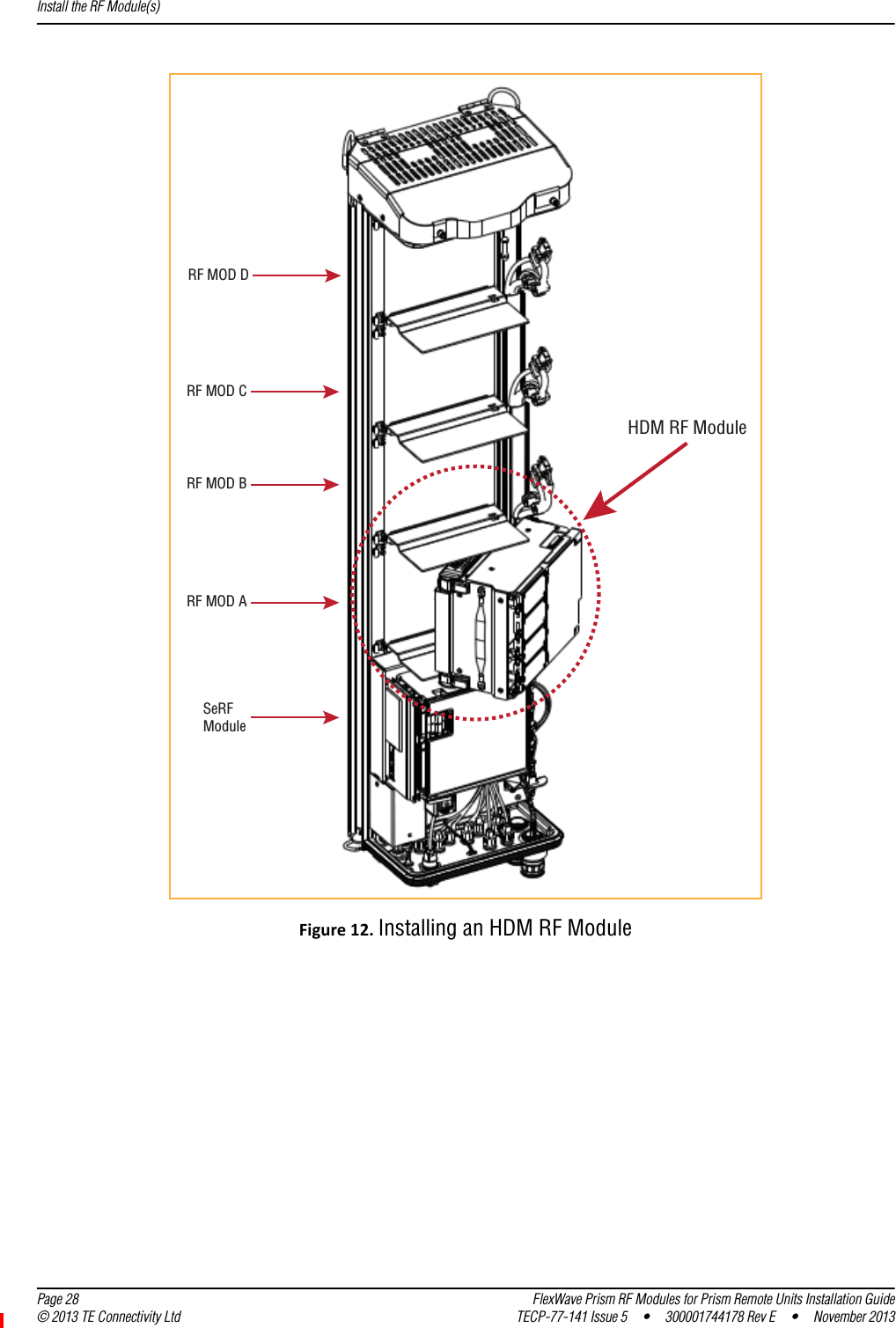
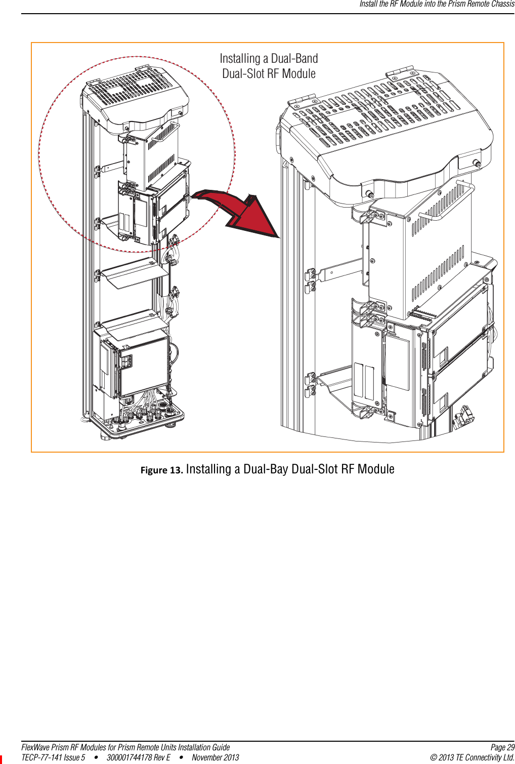
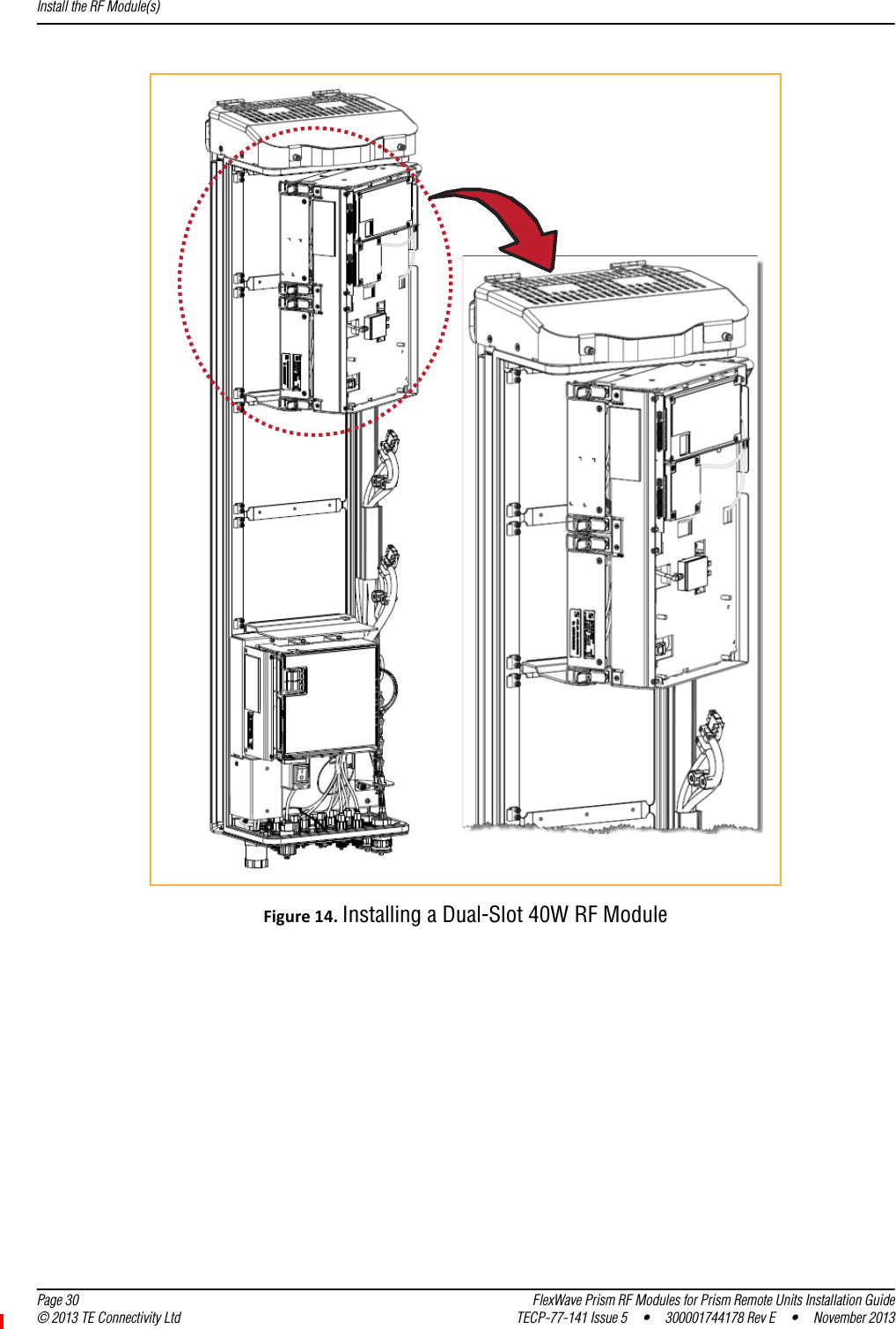
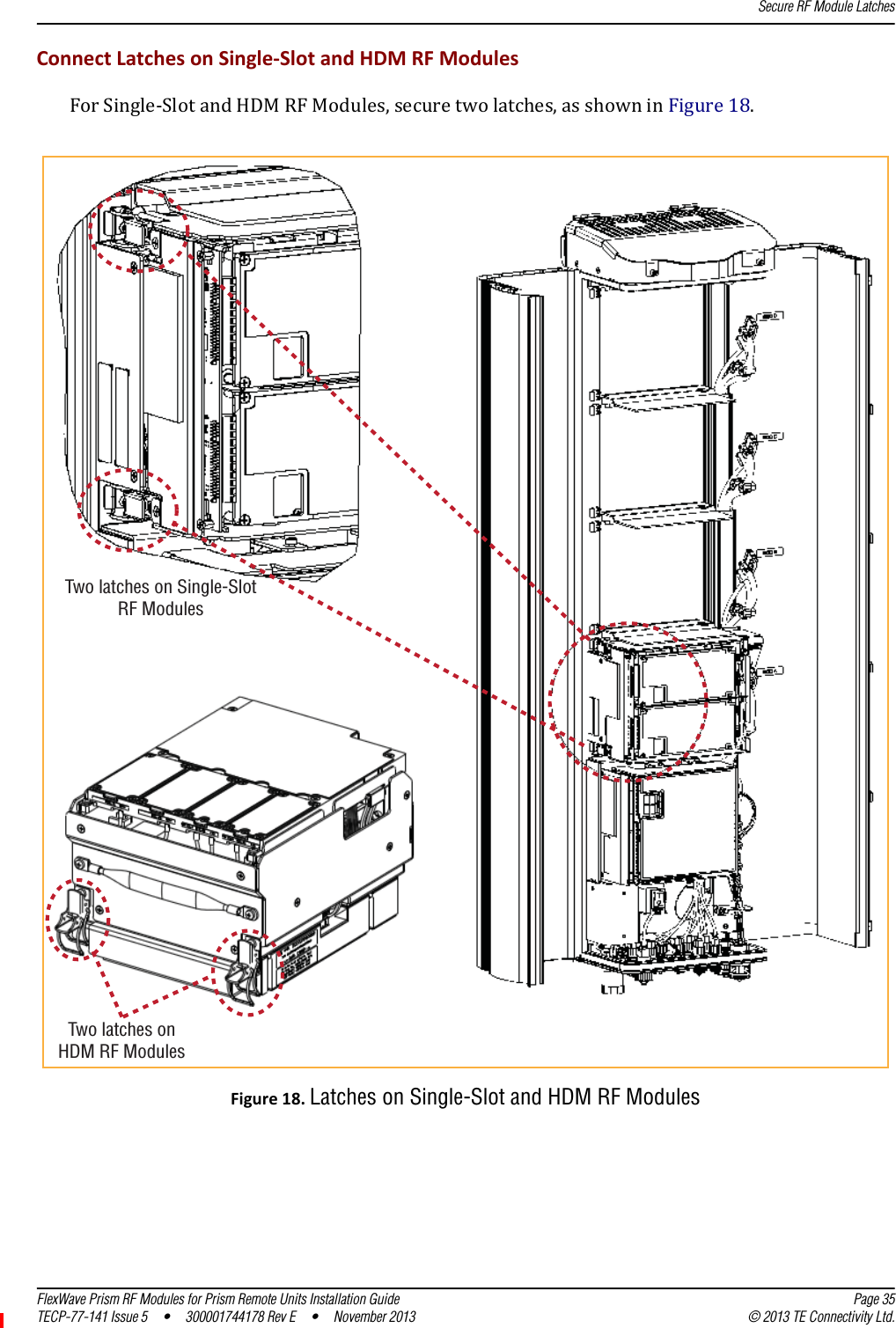
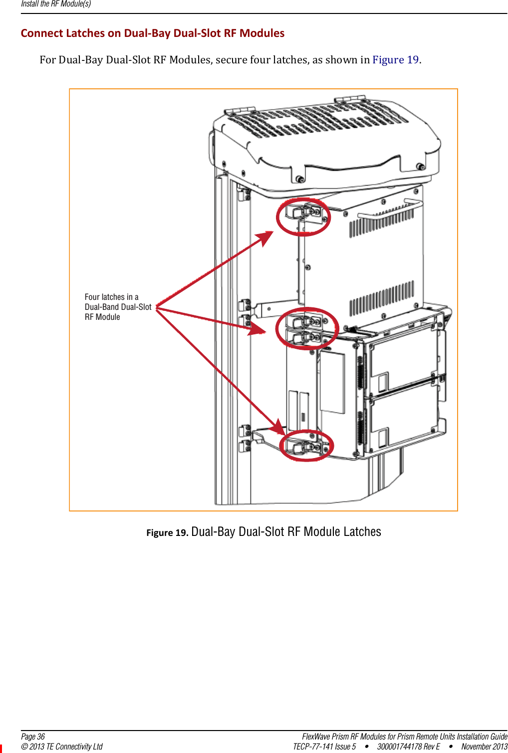
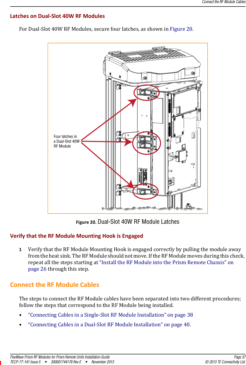
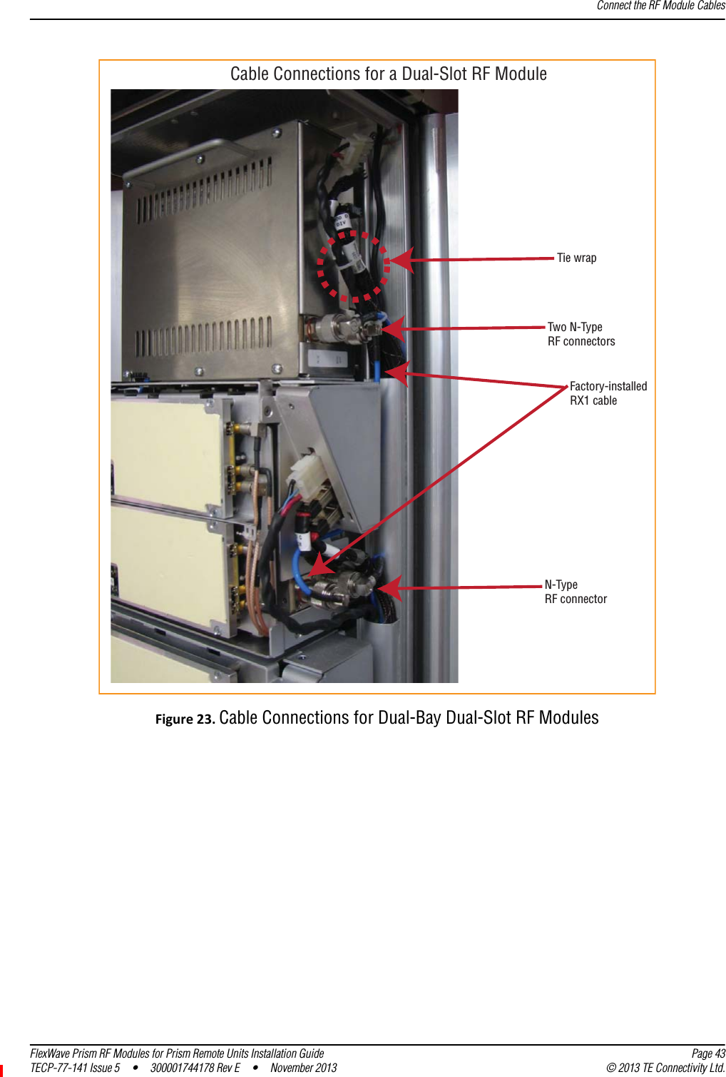
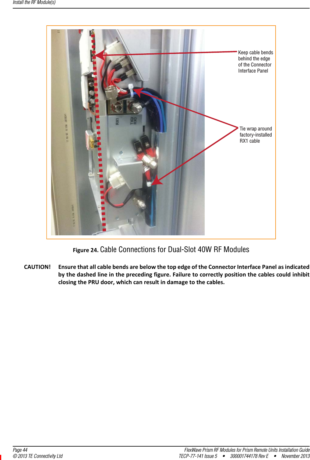
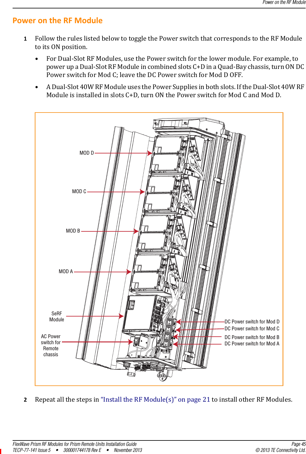
RF modules installation guide
Navigation menu
Upload a User Manual
Namespaces
Wiki Guide
HTML
PDF
Info
Views
User Manual
Discussion / Help
Navigation