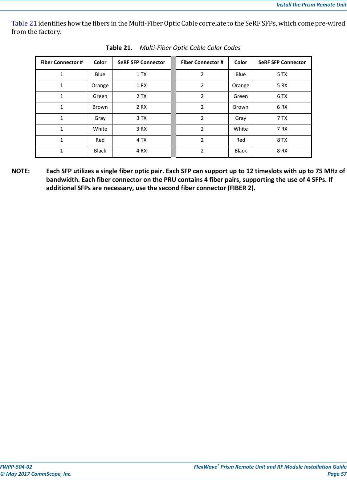
ADC Telecommunications PSMAWS3M FWP-Z4MT000MOD User Manual
ADC Telecommunications Inc FWP-Z4MT000MOD
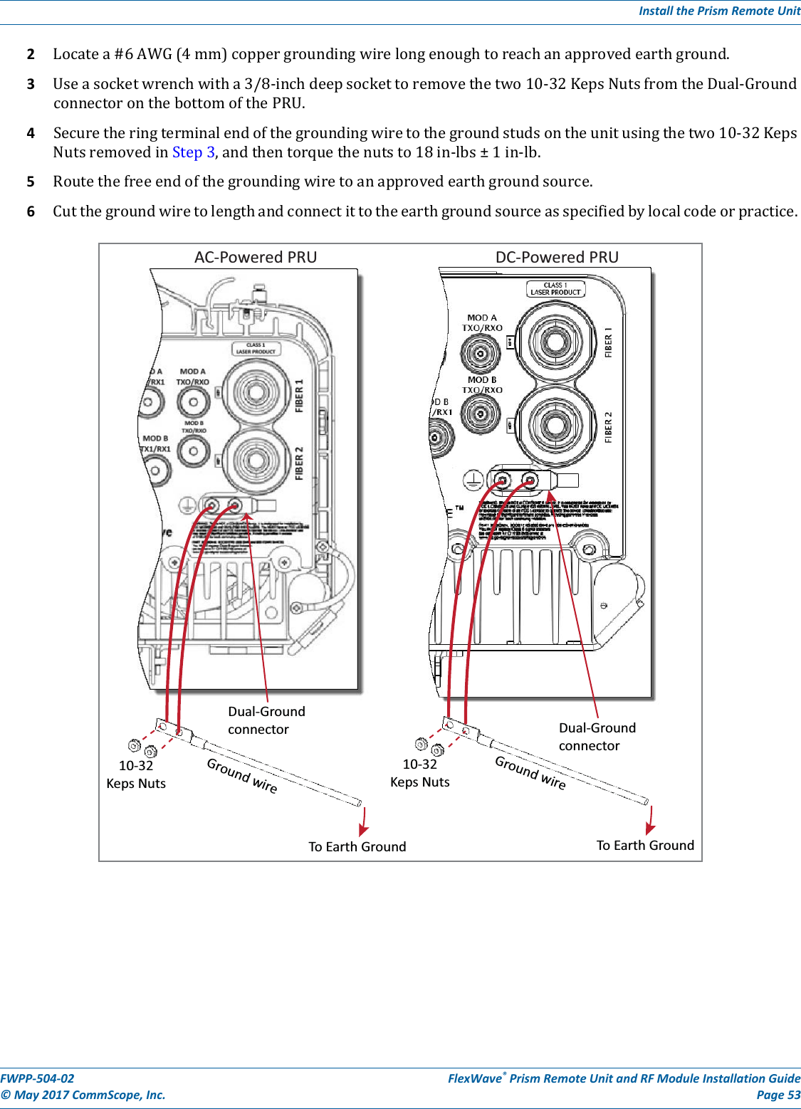
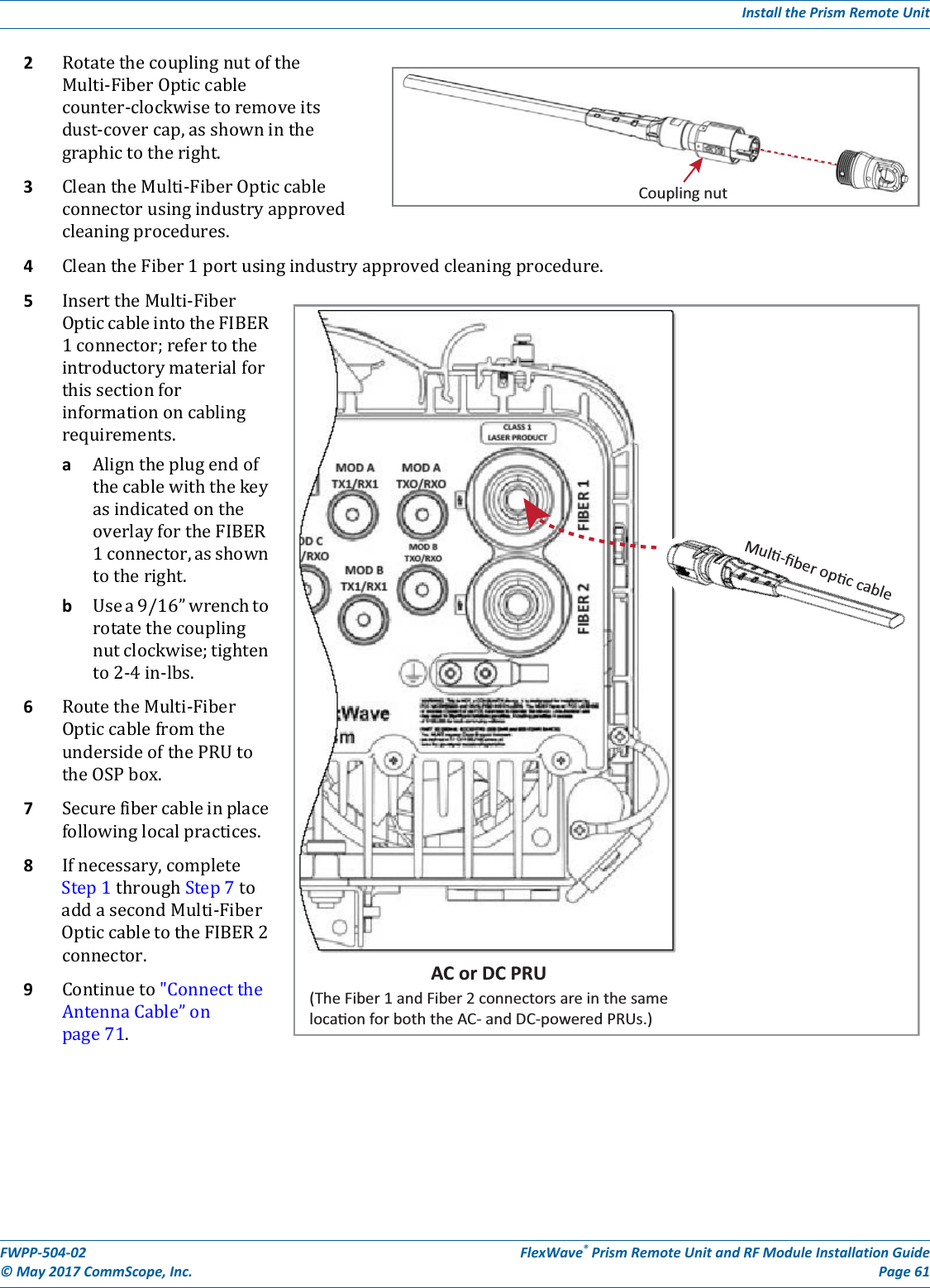
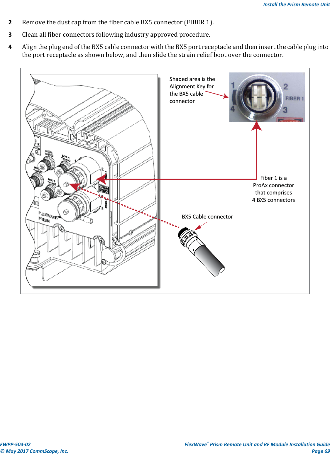
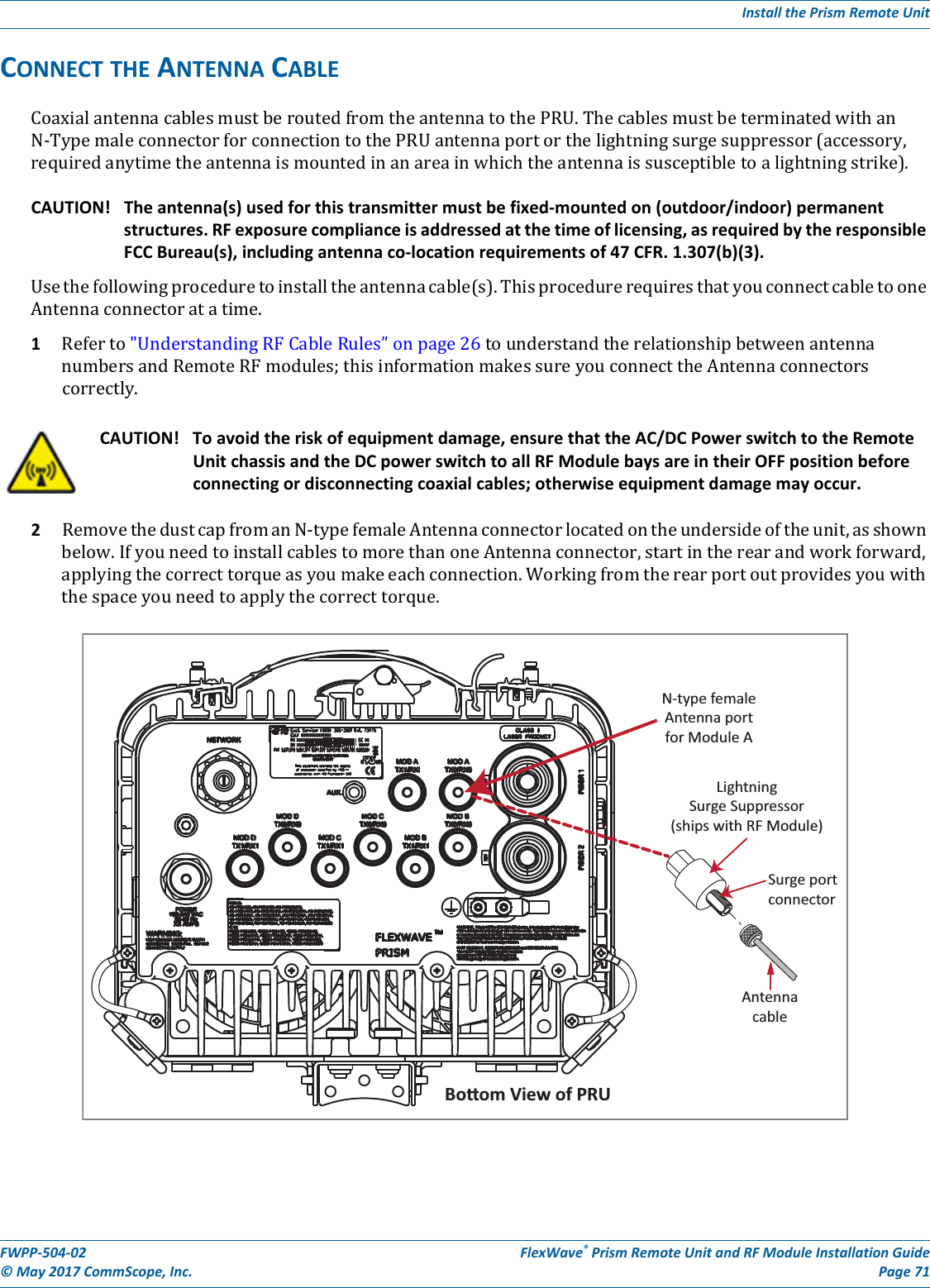
UserManual.wiki
>
ADC Telecommunications
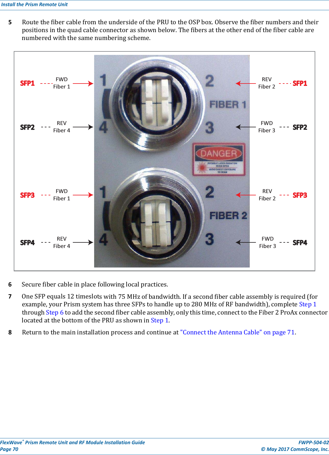
>
PSMAWS3M User Manual
User Manual
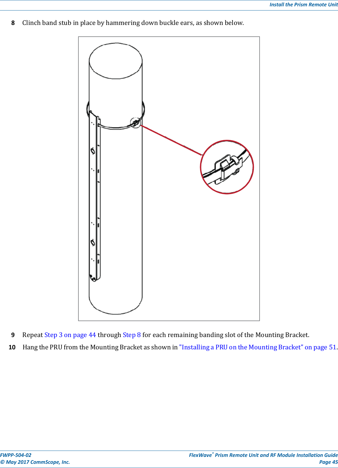
Navigation menu
Upload a User Manual
Namespaces
Wiki Guide
HTML
PDF
Info
Views
User Manual
Discussion / Help
Navigation
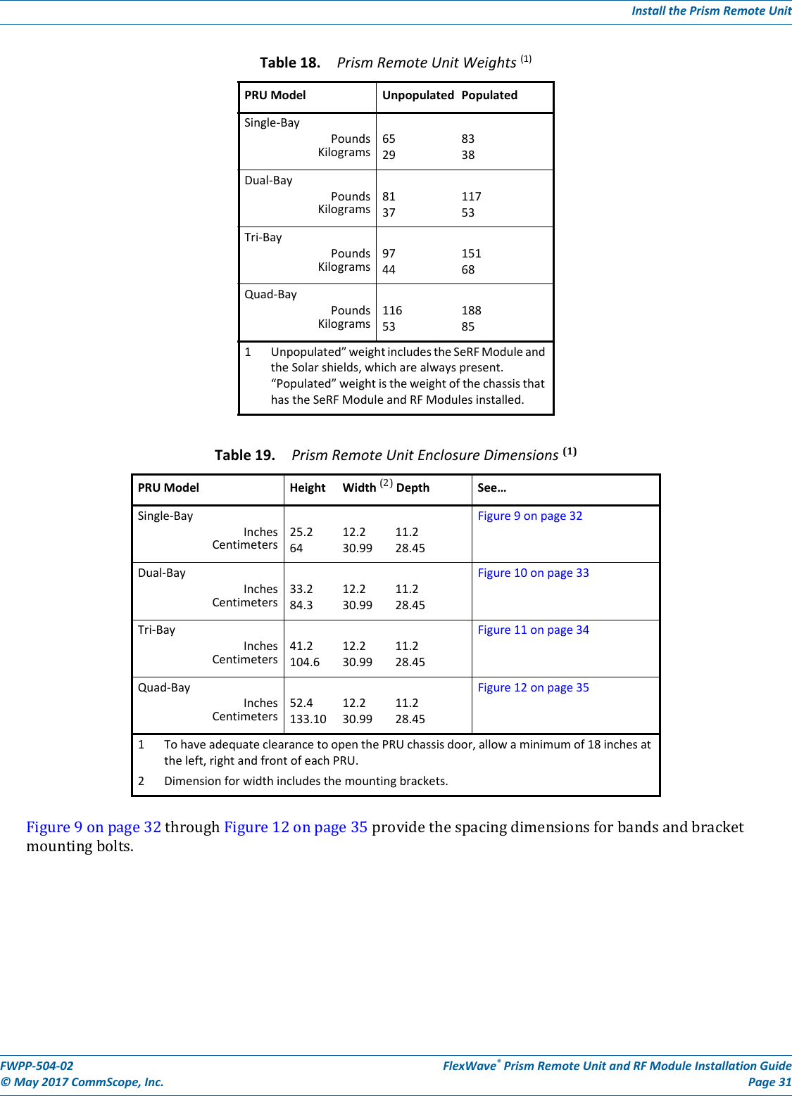
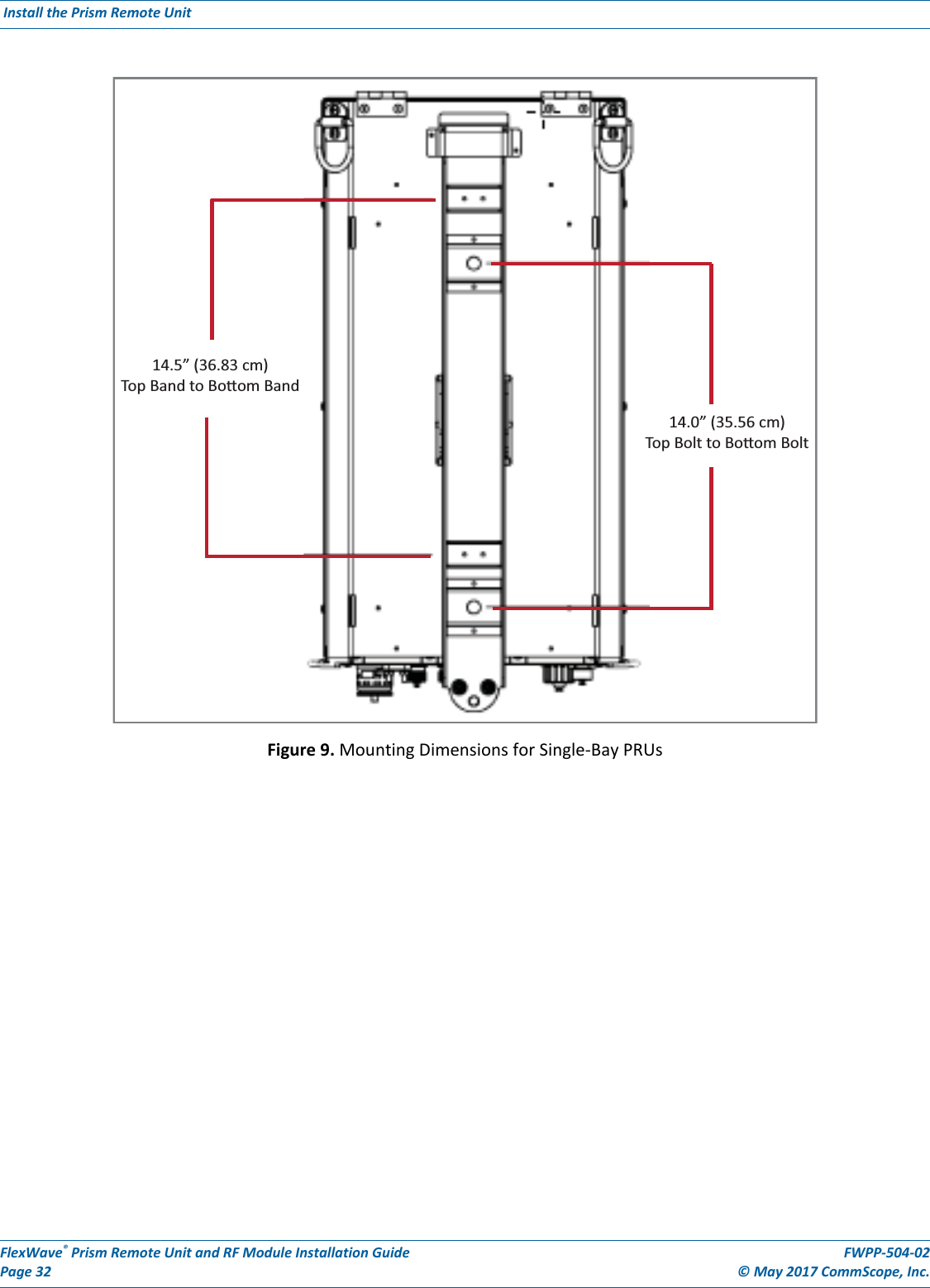
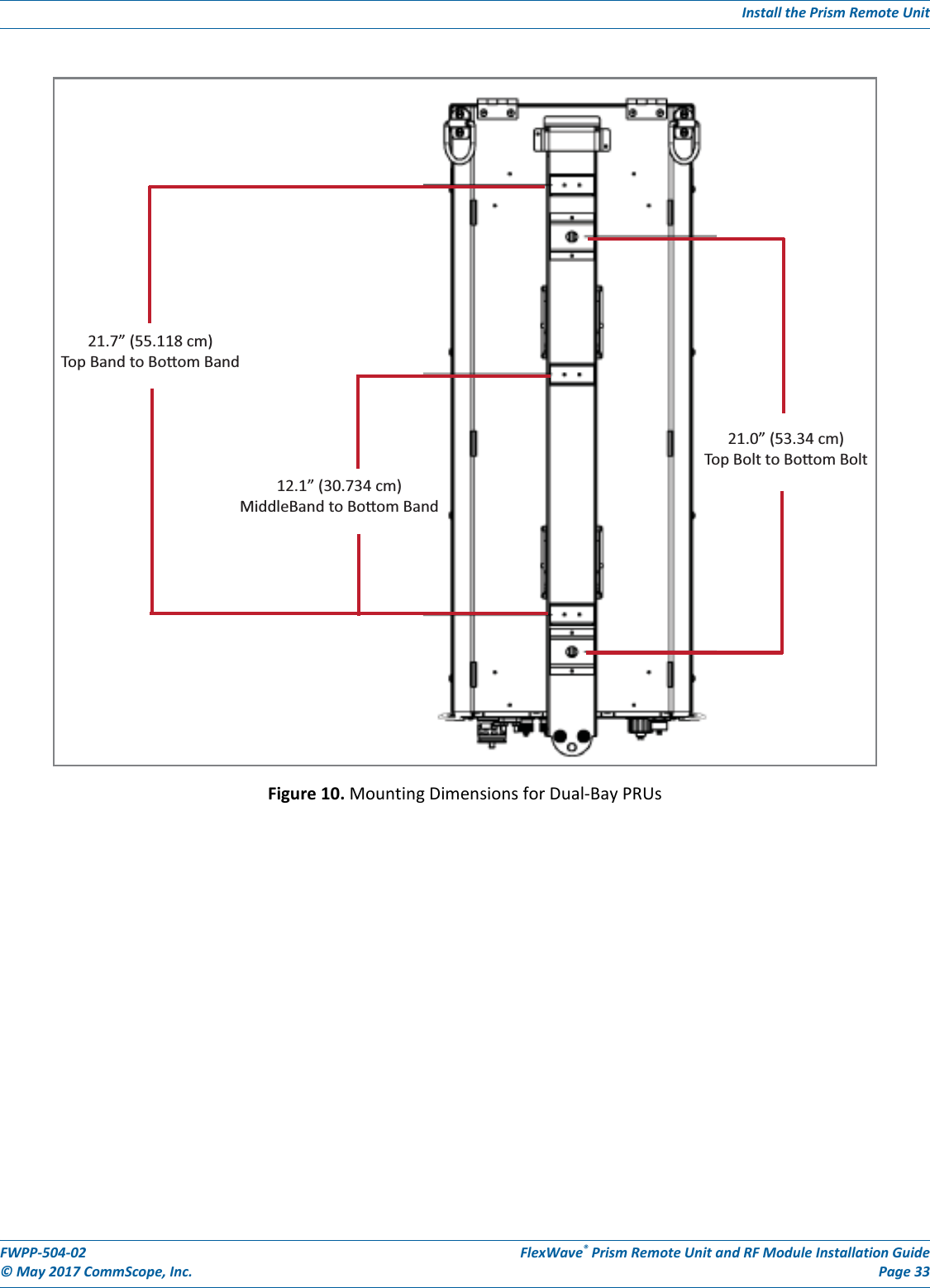
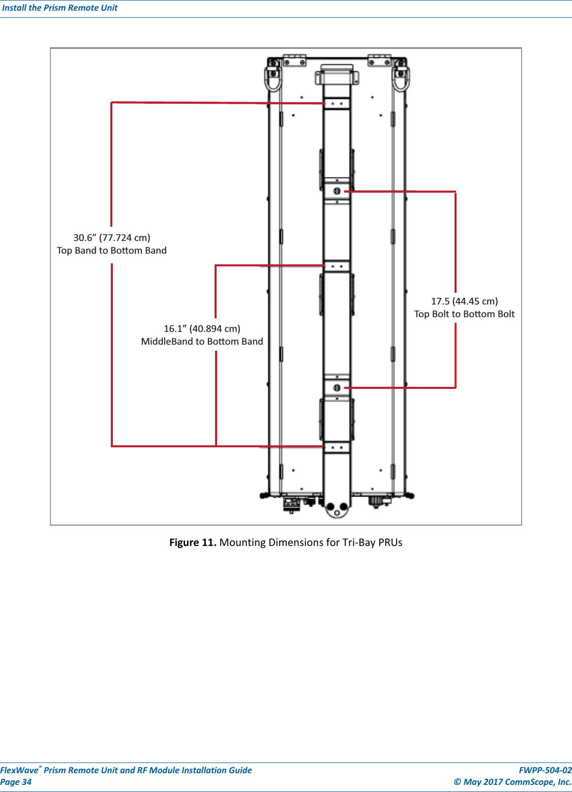
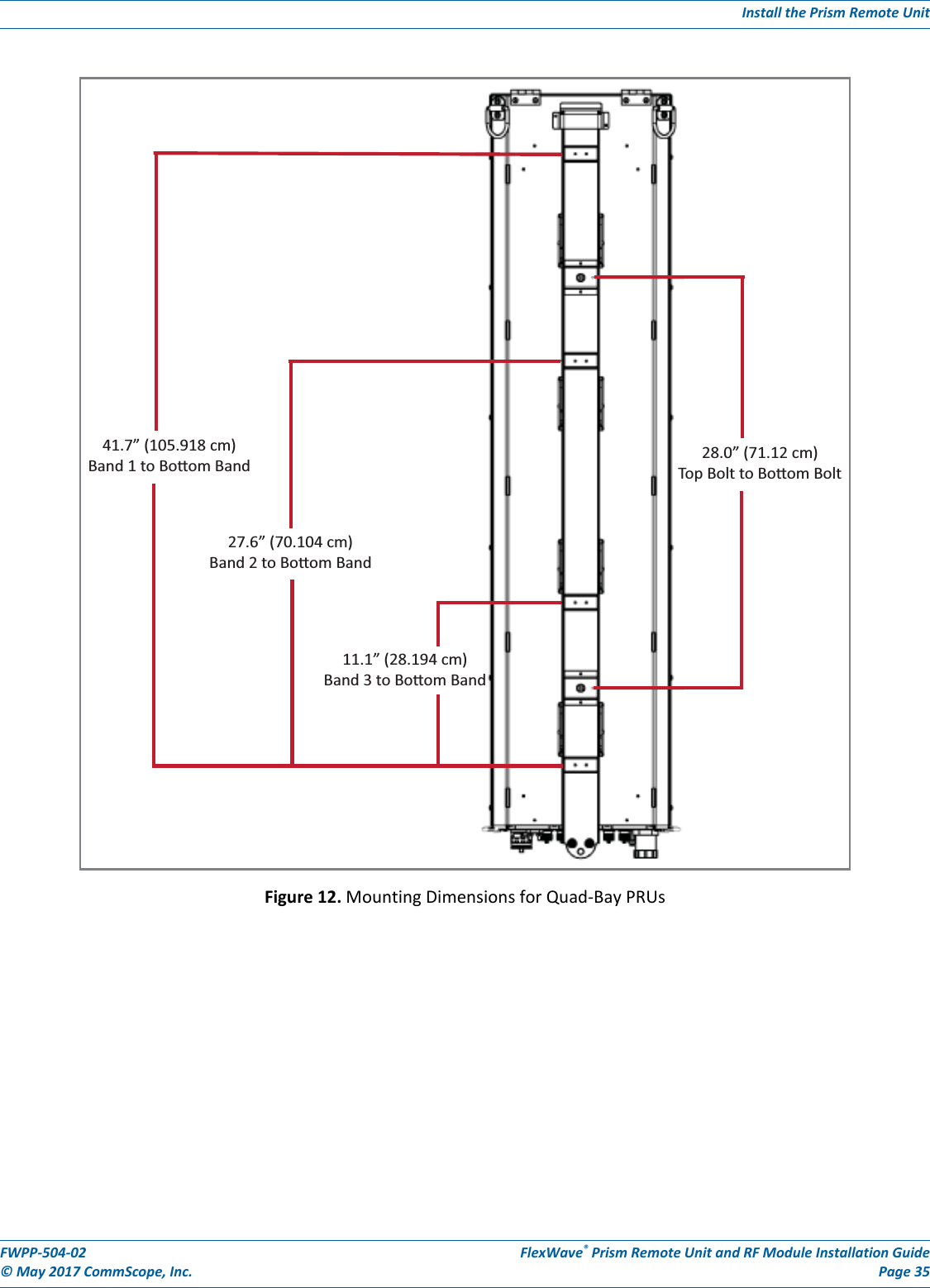

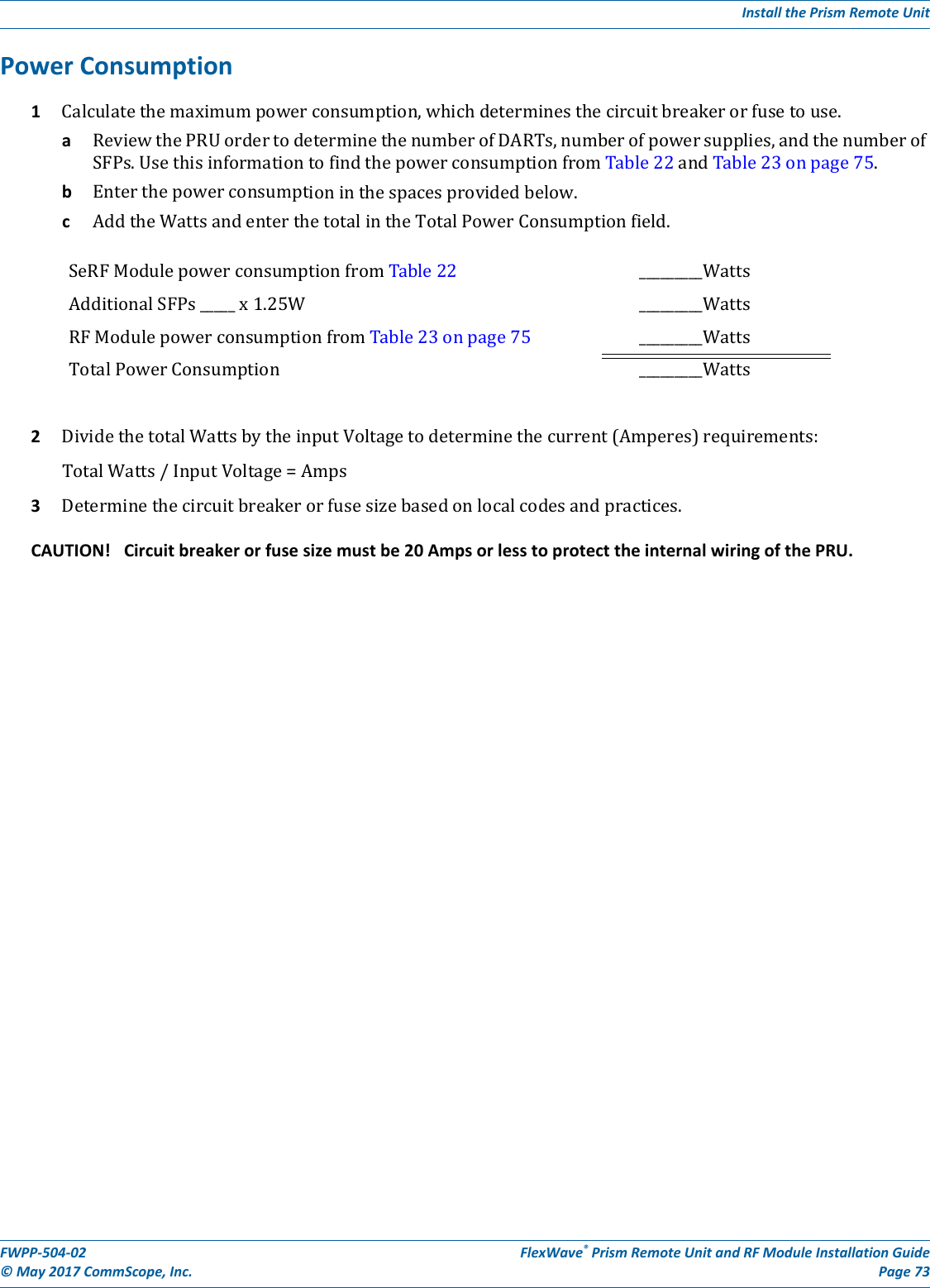
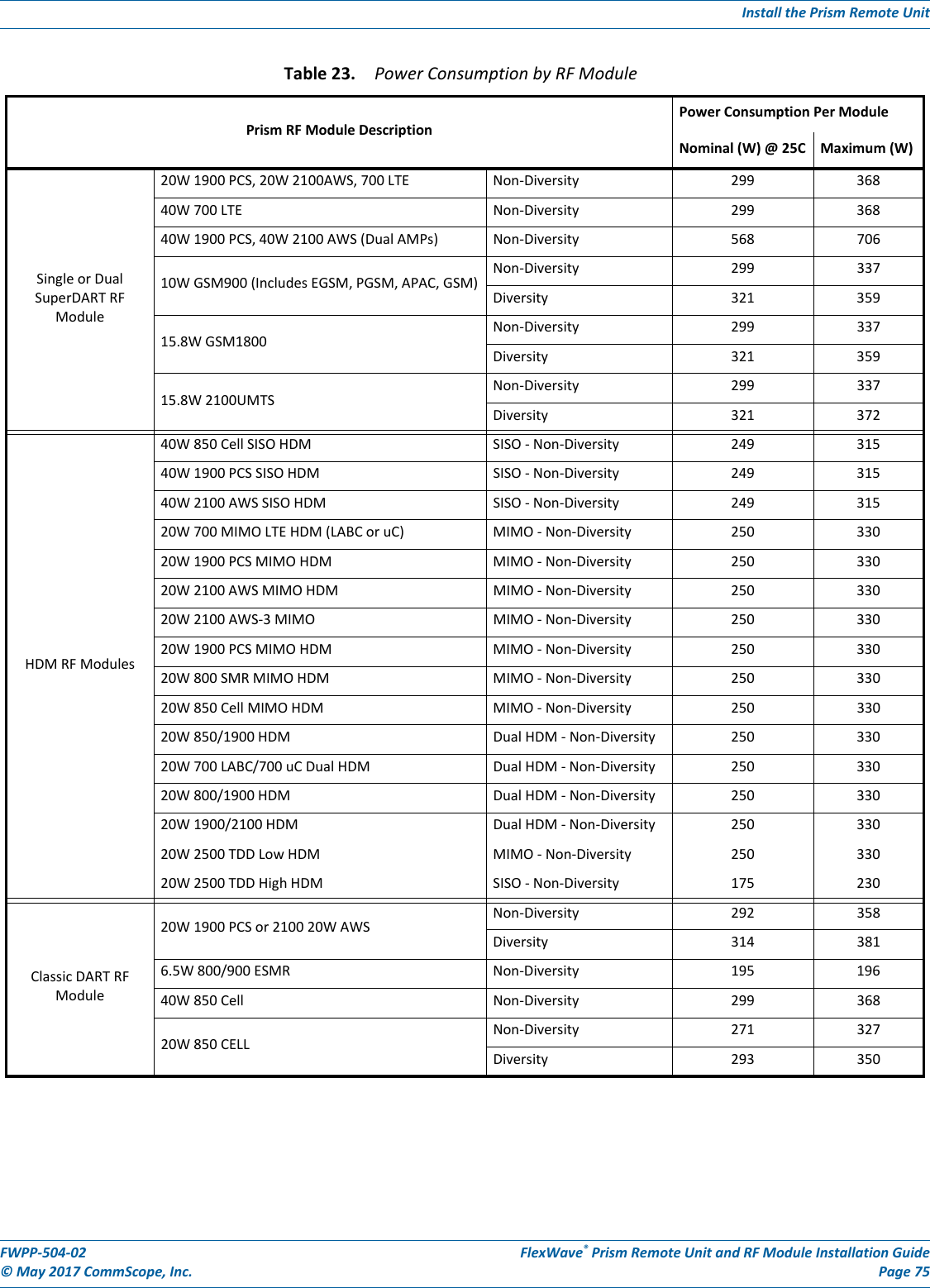
![FlexWave® Prism Remote Unit and RF Module Installation Guide FWPP-504-02Page 74 © May 2017 CommScope, Inc. Install the Prism Remote Unit Power Consumption TablesThePRUpowersuppliesare>80%efficient,bothACandDCversions.ThedatainTable22andTable23onpage75andthepower-supplyefficienciescanbeusedtoestimatetheinputcurrentforagivenPRUconfiguration.Usethefollowingequationtocalculatetheinputcurrentdraw:Input Current = (Total Power Consumption / 0.80) / Input Voltage Forexample,foraPRUwith1SeRFModule,1SFP(36WTypical,38WMax),andasingle20W850/1900HDMRFModule(250WTypical,330WMax),thentheTotalPowerConsumptionwouldbe286W(Typical)and368W(Max).Therefore,fora110VACinput,thecurrentestimatewouldbe3.25amps(Typical)and4.18amps(Max).Table 22. SeRF Module Power ConsumptionSeRF ModulePower Consumption per ModuleNominal (W) @ 25C Maximum (W)SeRF Module (1 SFP) [add 1.25W for each SFP added] 36 38](https://usermanual.wiki/ADC-Telecommunications/PSMAWS3M/User-Guide-3420244-Page-46.png)