ADC Telecommunications PSMAWS3M FWP-Z4MT000MOD User Manual
ADC Telecommunications Inc FWP-Z4MT000MOD
User Manual

Install the Prism Remote Unit
FWPP-504-02 FlexWave® Prism Remote Unit and RF Module Installation Guide
© May 2017 CommScope, Inc. Page 29
INSTALL THE PRISM REMOTE UNIT
ThissectiontellsyouhowtoinstallaPrismRemoteUnit(PRU).IfthePRUisalreadyinstalledandyouneedto
addoneormoreRFModules,goto"InstalltheRFModule(s)”onpage84.
PLANNING FOR A PRISM REMOTE UNIT INSTALLATION
BeforeyouunpackthePRU,youshouldfirstplanforwhereitwillbemountedandcollectthetoolsandsupplies
thatarerequiredtomountthePRUandthenconnectittoaPrismsystem.
NOTE: Installation of the Prism Remote Unit may proceed separately from the installation of the corresponding
Host Unit.
Safety Precautions
CAUTION! Do not power on the Prism Remote Unit chassis until instructed to do so in the installation procedures
included in this installation guide.
CAUTION! This is restricted access equipment and only qualified service personnel should open, service, or operate
this equipment using appropriate tools.
CAUTION! This equipment uses a Class 1 Laser per FDA/CDRH rules. Laser radiation can seriously damage the retina
of the eye. Do not look into the ends of any optical fiber. Do not look directly into the optical transceiver
of any digital unit or exposure to laser radiation may result. An optical power meter should be used to
verify active fibers. A protective cap or hood MUST be immediately placed over any radiating
transceiver or optical fiber connector to avoid the potential of dangerous amounts of radiation
exposure. This practice also prevents dirt particles from entering the adapter or connector.
CAUTION! Wet conditions increase the potential for receiving an electrical shock when installing or using
electrically-powered equipment. Do not perform service on the Prism Remote Unit or its components
in a wet location, if it is raining or snowing, or if impending rain or snow has been observed.
CAUTION! Exterior surfaces of the Prism Remote Unit may be hot. Use caution during servicing.
CAUTION! Contact with overhead cables, especially electric power cables, could cause serious personal injury or
death. Before beginning the installation, check the location of all overhead wires and cables and take
precautions to avoid accidental contact.
CAUTION! Use appropriate lifting equipment when unpacking, moving or installing the Fullband Remote Unit. Do
not stand under the Fullband Remote Unit as it is hoisted into position for installation. A failure of the
lifting equipment could result in serious personal injury.
CAUTION! The location in which the Remote Unit is installed (utility pole, mast, or flat surface) must be able to
support the weight of a fully-populated Fullband Remote Unit; see Table 18 on page 31.
CAUTION! This system is an RF Transmitter and continuously emits RF energy. Maintain 3 foot (91.4 cm) minimum
clearance from the antenna while the system is operating. Wherever possible, shut down the RAN
before servicing the antenna.

FlexWave® Prism Remote Unit and RF Module Installation Guide FWPP-504-02
Page 30 © May 2017 CommScope, Inc.
Install the Prism Remote Unit
CAUTION! Always allow sufficient fiber length to permit routing of patch cords and pigtails without severe bends.
Fiber optic patch cords or pigtails may be permanently damaged if bent or curved to a radius of less than
2 inches (5.1 cm).
CAUTION! Always use an Electro-Static Discharge (ESD) wrist strap whenever you work with the Prism Remote Unit
or its components. Make sure that it maintains maximum contact with bare skin. ESD grounding straps
are available with banana plugs, metal spring clips, or alligator clips. To ensure adequate grounding,
connect the ESD wrist strap to any bare metal surface of the Prism Remote Unit chassis (which may
require that you scrape off some of its protective coating), or to the Dual-Ground Connector at the
bottom of the unit. For information on the Dual-Ground Connector, see "Ports and Connectors” on
page 7.
CAUTION! Service personnel must confirm that the perimeter gasket and door-to-door gaskets are in place when
closing the Remote Unit doors after servicing.
Mounting Plans
ThePRUhasalow-profiledesignthatrequiresminimalrealestateforinstallation.Thebasicdimensionsand
weightsofthePRUarelistedinTable19onpage31andTable18onpage31.
ThePRUshouldbemountedonautilitypole,mast,oronaflatsurface.AMountingBracketshipswitheach
Remote.Installationconsistsofsecuringthebrackettothemountingsurface(wood,concrete,orsteel)andthen
hangingtheunitfromthebracket.thePRUshouldonlybemountedinarestrictedaccesslocation.
BeforemountingthePRU,makesurethatthefollowingrequirementsaremet.
•ThePRUmust
–beinstalledonlyinarestricted-accesslocation
–mustbelocatedasspecifiedinthesystemdesignplan(notdocumentedhere).Ifasystemdesignplanhas
notbeenprepared,consultwiththeTechnicalSupportforWirelessProductsteamforassistance(see
"DCCSGlobalTechnicalSupport”onpage124).
–musthavereadyaccesstothespecifiedACorDCpowersource.
•IfyoumountthePRUinahorizontalposition,youmustmountitataslightangle,withthetopofthePRU
chassisangledhigherthanthebottom,whichcreatesaslopethatallowswaterorsnowtorunoffthePRU
chassis.Ifitismountedindoors,nosloperequired.
•IfyoumountthePRUinanupside-downhorizontalposition(i.e.,aceilingmount),attachsafetyleashesthat
cansupporttheweightofafullypopulatedchassis(seeTable18onpage31).
•Thesitechosenmust
–conformtoalllocalcodes;requiredpermitsmustbeobtainedpriortomountingaPRU
–complywiththeunitenvironmentalspecifications
–beopentofreeairspaceonthebottom(cableentryend),thetop,thefront,andbothsides
–allowadequateclearanceatthebottomofthePRUtoprovideaccessforattachingcablesandforviewing
theLEDindicator
–provide18inches(45.7cm)ofclearanceonthefrontandbothsidesofthePRUtoallowdoorstobe
openedforserviceandtoallowfreeaircirculation
–canbearthesizeandweightofthePRUenclosure,seeTable18onpage31andTable19onpage31
Install the Prism Remote Unit
FWPP-504-02 FlexWave® Prism Remote Unit and RF Module Installation Guide
© May 2017 CommScope, Inc. Page 31
Figure9onpage32throughFigure12onpage35providethespacingdimensionsforbandsandbracket
mountingbolts.
Table 18. Prism Remote Unit Weights (1)
PRU Model Unpopulated Populated
Single-Bay
Pounds
Kilograms
65 83
29 38
Dual-Bay
Pounds
Kilograms
81 117
37 53
Tri-Bay
Pounds
Kilograms
97 151
44 68
Quad-Bay
Pounds
Kilograms
116 188
53 85
1 Unpopulated” weight includes the SeRF Module and
the Solar shields, which are always present.
“Populated” weight is the weight of the chassis that
has the SeRF Module and RF Modules installed.
Table 19. Prism Remote Unit Enclosure Dimensions (1)
PRU Model Height Width (2) Depth See…
Single-Bay
Inches
Centimeters
25.2 12.2 11.2
64 30.99 28.45
Figure 9 on page 32
Dual-Bay
Inches
Centimeters
33.2 12.2 11.2
84.3 30.99 28.45
Figure 10 on page 33
Tri-Bay
Inches
Centimeters
41.2 12.2 11.2
104.6 30.99 28.45
Figure 11 on page 34
Quad-Bay
Inches
Centimeters
52.4 12.2 11.2
133.10 30.99 28.45
Figure 12 on page 35
1 To have adequate clearance to open the PRU chassis door, allow a minimum of 18 inches at
the left, right and front of each PRU.
2 Dimension for width includes the mounting brackets.
FlexWave® Prism Remote Unit and RF Module Installation Guide FWPP-504-02
Page 32 © May 2017 CommScope, Inc.
Install the Prism Remote Unit
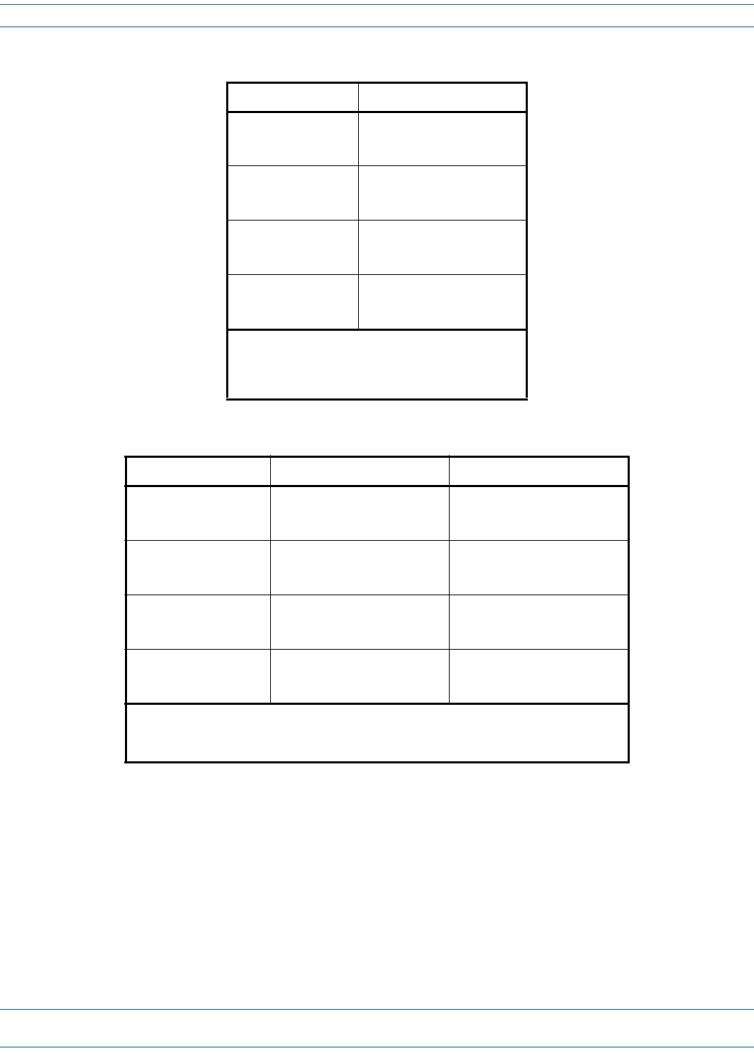
Figure 9. Mounting Dimensions for Single-Bay PRUs
14.5” (36.83 cm)
Top Band to Boom Band
14.0” (35.56 cm)
Top Bolt to Boom Bolt
Install the Prism Remote Unit
FWPP-504-02 FlexWave® Prism Remote Unit and RF Module Installation Guide
© May 2017 CommScope, Inc. Page 33
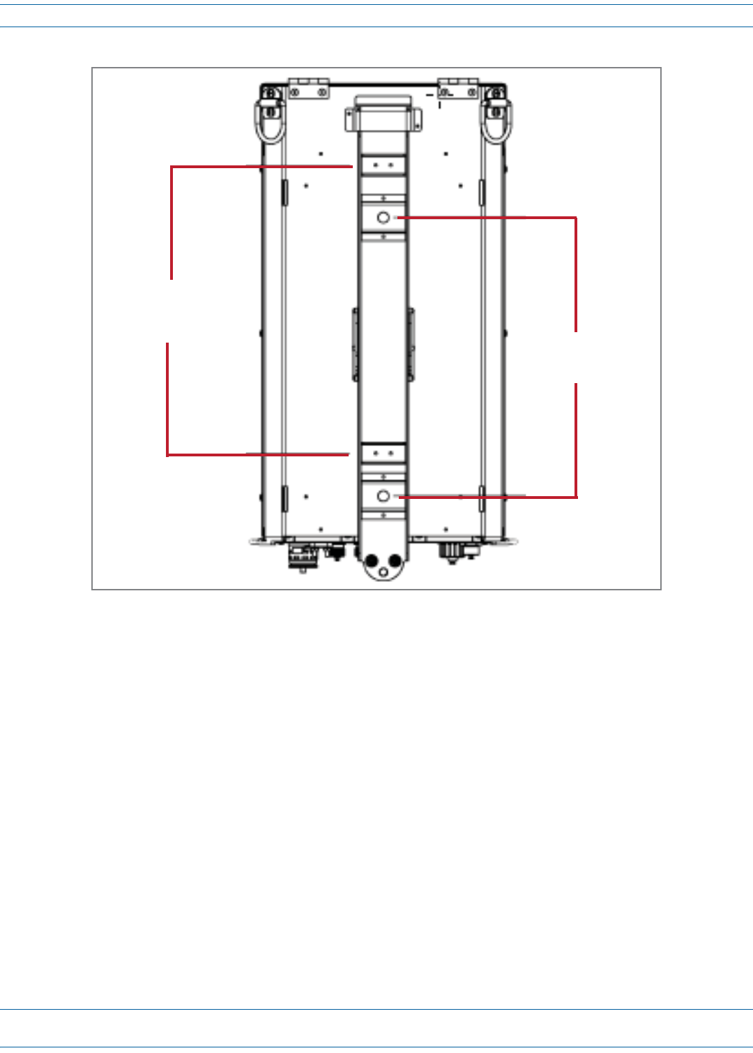
Figure 10. Mounting Dimensions for Dual-Bay PRUs
21.7” (55.118 cm)
Top Band to Boom Band
21.0” (53.34 cm)
Top Bolt to Boom Bolt
12.1” (30.734 cm)
MiddleBand to Boom Band
FlexWave® Prism Remote Unit and RF Module Installation Guide FWPP-504-02
Page 34 © May 2017 CommScope, Inc.
Install the Prism Remote Unit
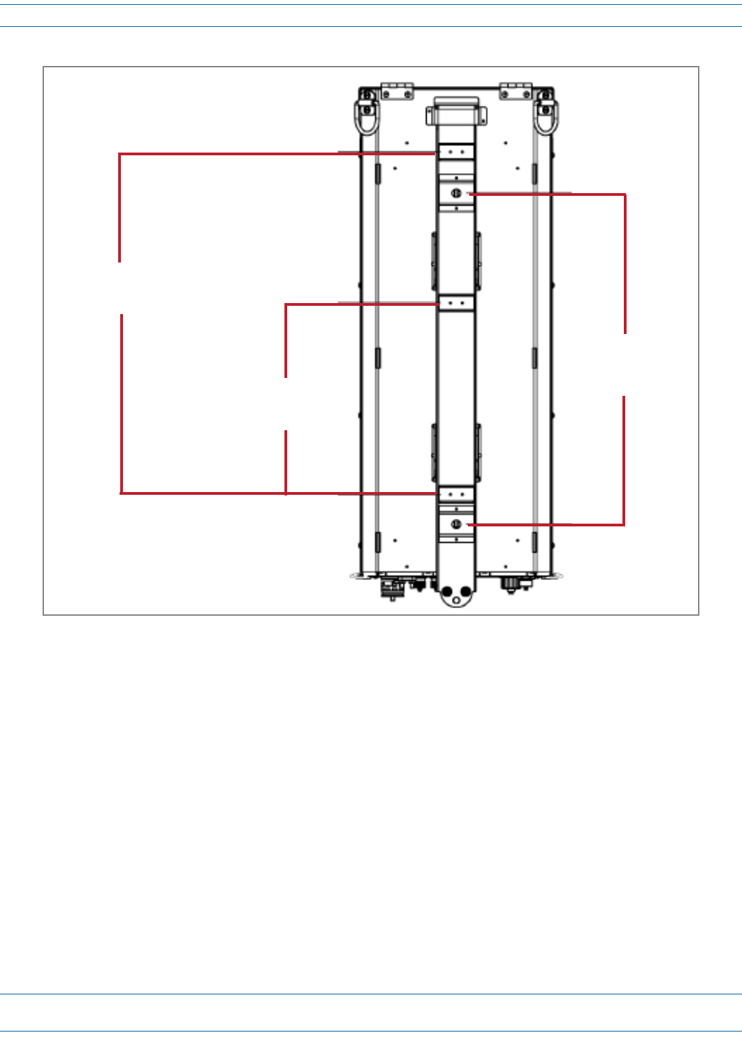
Figure 11. Mounting Dimensions for Tri-Bay PRUs
30.6” (77.724 cm)
Top Band to Boom Band
17.5 (44.45 cm)
Top Bolt to Boom Bolt
16.1” (40.894 cm)
MiddleBand to Boom Band
Install the Prism Remote Unit
FWPP-504-02 FlexWave® Prism Remote Unit and RF Module Installation Guide
© May 2017 CommScope, Inc. Page 35
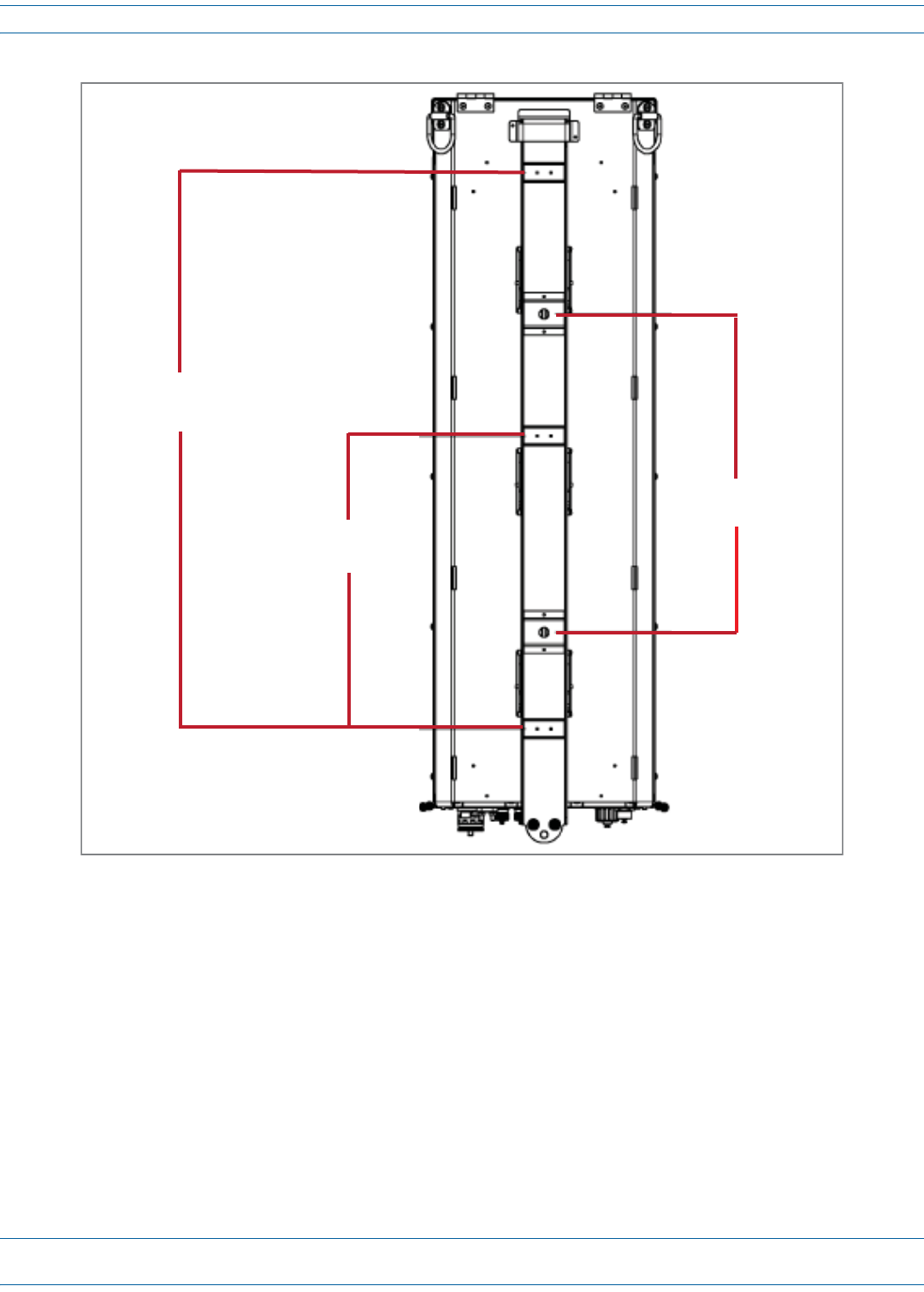
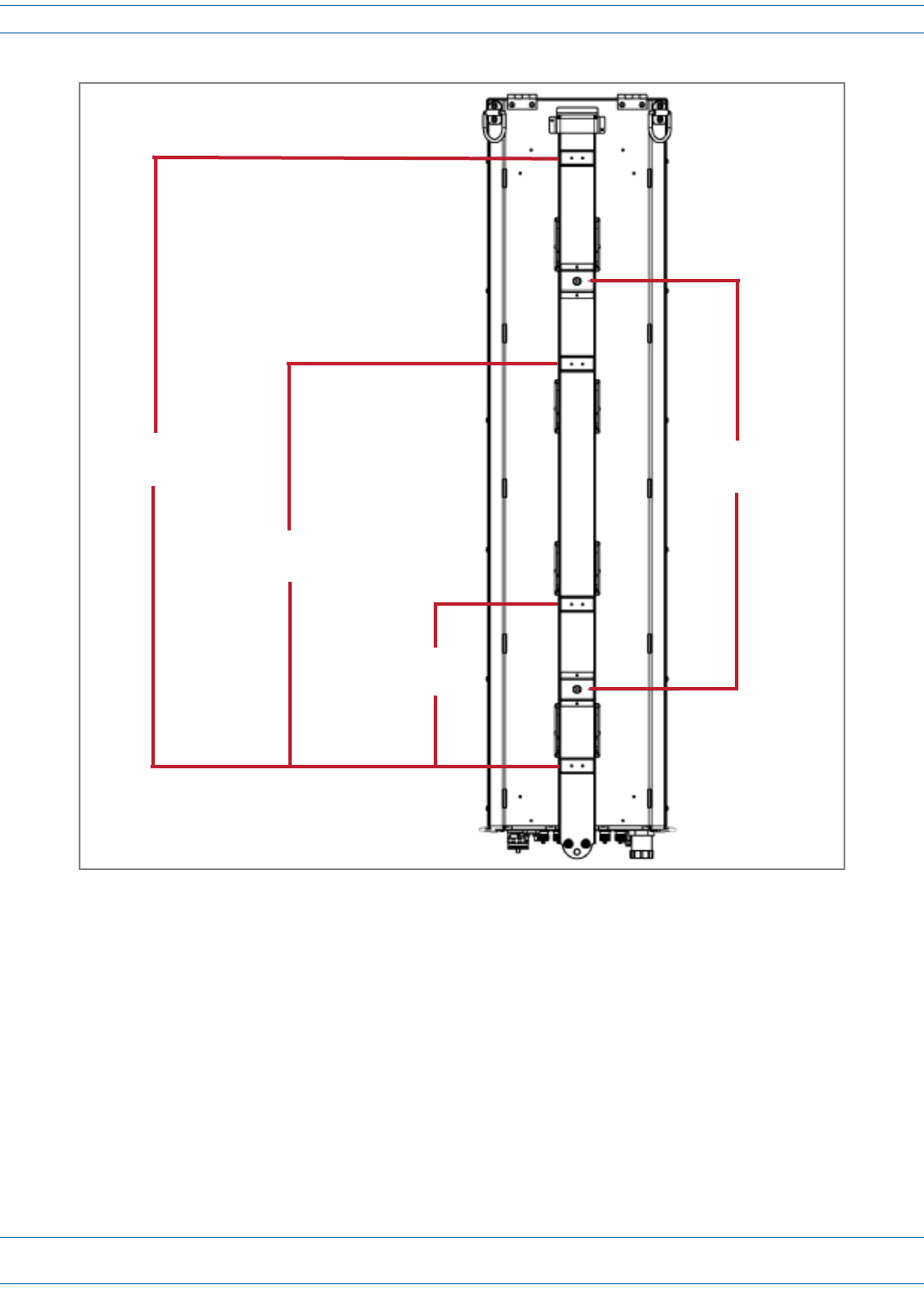
Figure 12. Mounting Dimensions for Quad-Bay PRUs
41.7” (105.918 cm)
Band 1 to Boom Band 28.0” (71.12 cm)
Top Bolt to Boom Bolt
27.6” (70.104 cm)
Band 2 to Boom Band
11.1” (28.194 cm)
Band 3 to Boom Band
FlexWave® Prism Remote Unit and RF Module Installation Guide FWPP-504-02
Page 36 © May 2017 CommScope, Inc.
Install the Prism Remote Unit
Installation Tools and Supplies
ThetoolsandanyadditionalmaterialsrequiredforinstallandmountthePRUaredependentonthemounting
location.
Tools Required for All Mounting Methods
TheMountingBracketshipswiththePRU—itsecuresthePRUtoitspackingcrate.Allinstallationsrequireat
leastoneeachofthefollowing,whichmustbeprovidedbytheinstaller:
•tapemeasure
•pencilorothermarkingdevice
•3/8-inchFlat-Bladescrewdriver
•liftingequipmentforPRU.
Additional Tools and Supplies Required for Steel-Pole Mounting
WhenmountingthePRUtoasteelpole,inadditiontothesupplieslistedin"ToolsRequiredforAllMounting
Methods”onpage36thefollowingsuppliesareneeded:
•onehammer,>16-ounces
•oneStrapTensioning/ClampingTool(UlineModelNo.H-1273,orequivalent)
•Table20showsthenumberofstainless-steelstrapsandstainless-steelbucklesrequiredforeachPRUtype,
inwhichyoumusthavethesamenumberofbucklesasstraps.
–Use1/2-inchto3/4-inch201,301,304or316Stainless-SteelStrappingwithaminimumtensilestrength
of1500pounds(UlineModelNo.S-11329,orequivalent).
–UseStainless-SteelBucklesdesignedspecificallyfortheabove-mentionedstrapping(UlineModelNo.
S-11331,orequivalent).
Table 20. Required Stainless-Steel Bands for Steel-Pole Mounting
CommScope Catalog Number Number of Bands Required for Installation
FP4-XXXXX0021XXRU - Quad-Bay Remote 4
FP3-XXXXX0021XXRU - Tri-Bay Remote
3
FP2-XXXXX0021XXRU - Dual-Bay Remote
FP1-XXXXX0021XXRU - Single-Bay Remote 2

Install the Prism Remote Unit
FWPP-504-02 FlexWave® Prism Remote Unit and RF Module Installation Guide
© May 2017 CommScope, Inc. Page 37
Additional Tools and Supplies Required for Wood-Pole Mounting
WhenmountingthePRUtoawoodpole,inadditiontothesupplieslistedin"ToolsRequiredforAllMounting
Methods”onpage36,thefollowingsuppliesareneeded:
•oneelectricdrill,1/2-inchorlarger
•one1/2-inchdrillbit
•two1/2-inchsquare-headthrough-boltorequivalentthatislongenoughtoextendthroughtheutilitypole
•two1/2-inchsquarenutorequivalent
•two1/2-inchsquarewasher
•oneormoreappropriately-sizedwrenchesforthrough-bolts
•oneadjustablewrench
Additional Tools and Supplies Required for Flat-Surface Mounting
•oneelectricdrill,1/2-inchorlarger
•one5/8-inchwrench
•two1/2-inchflatwashers
•two1/2-inchlockwashers
•formasonrywallinstallationsonly:
–two1/2x11/2-inchhexboltsformasonrywallinstallations
–two1/2-inchconcretewallanchorsformasonrywallinstallations
–two3/4-inchmasonrydrillbit(formasonrywallinstallations)
•forwood-framedwallinstallationsonly:
–one3/4-inchpressure-treatedplywood,sizedtoaccommodatethePRU(seeTable19onpage31)
–fastenersforsecuring3/4-inchplywoodtowall
–one9/16-inchstandarddrillbit
–two1/2x1-inchhexbolts
–two1/2-inchTeeNuts

FlexWave® Prism Remote Unit and RF Module Installation Guide FWPP-504-02
Page 38 © May 2017 CommScope, Inc.
Install the Prism Remote Unit
Tools and Supplies Required to Connect a PRU
TheinstallationhardwareprovidedwithaPRUislistedbelow.
•One15-foot(4.6m)ACPowerCable,thatisincludedwiththePRU
•Oneofthefollowing,whichispurchasedseparatelyfromthePRU:
–ProAxcableassemblyforlegacyPRUsusingaProAxConnector
–HMFOCCableAssemblyforHMFOCConnector
–FiberPass-ThroughCableAssembly(providedbyinstaller)
CAUTION! The hardware used to package the PRU for shipment is not intended for installations of a PRU and
should be kept with the Prism Remote Unit packaging. Do not use the shipping hardware when installing
a PRU.
AdditionalhardwareortoolsrequiredtoconnectaPRUtoaPrismsystemislistedbelow.
•Electro-StaticDischarge(ESD)wriststrap
•SocketWrenchand3/8-inchDeepSocket
•Wirecutters
•Wirestripper
•9/64-inchAllen™wrench(dual-slotRFModuleinstallationsonly)
•42MMwrenchcapableof44in-lbtorque(therecommendedN-Connectortorqueis8in-lb)
•Phillipsscrewdrivercapableof18in-lbtorque
•N-Typemaleconnectors
•ToolkitforattachingN-Typeconnectorstocoaxialcable
•Fibercleaningkit
•#6AWG(4mm)copperwireandsplice
•Tools,Junctionbox,conduit,fasteners,connectors,andwiretoinstallanexteriorACcircuit
•RJ-45connector(ifmakingapermanentexternalnetworkcableconnection)
•ForDC-poweredPRUs,an8AWGor6AWG,3-or4-conductorpowercableratedforoutdooruse,withthe
followingrequirements.
–Thewirecolorsmustbegreen,red,andblack.
–Thecablediametermustbe.71to.98inches.
–Ifa4-conductorpowercableisused,theextraconductorcanbesnippedoffbeforeinstallation.
–Ifusing6AWGwire,theinstallermustprovideanduse#10studsize,6AWGringterminals.
Install the Prism Remote Unit
FWPP-504-02 FlexWave® Prism Remote Unit and RF Module Installation Guide
© May 2017 CommScope, Inc. Page 39
UNPACK AND INSPECT THE PRISM REMOTE UNIT AND COMPONENTS
1Inspecttheexterioroftheshippingcontainer(s)forevidenceofroughhandlingthatmayhavedamagedthe
componentsinthecontainer.
2Checkthecontentsfordamageandverifywiththepackingslip.
Ifdamageisfoundorpartsaremissing,fileaclaimwiththecommercialcarrierandnotifyCommScope
CustomerService(see"DCCSGlobalTechnicalSupport”onpage124).Savethedamagedcartonsfor
inspectionbythecarrier.
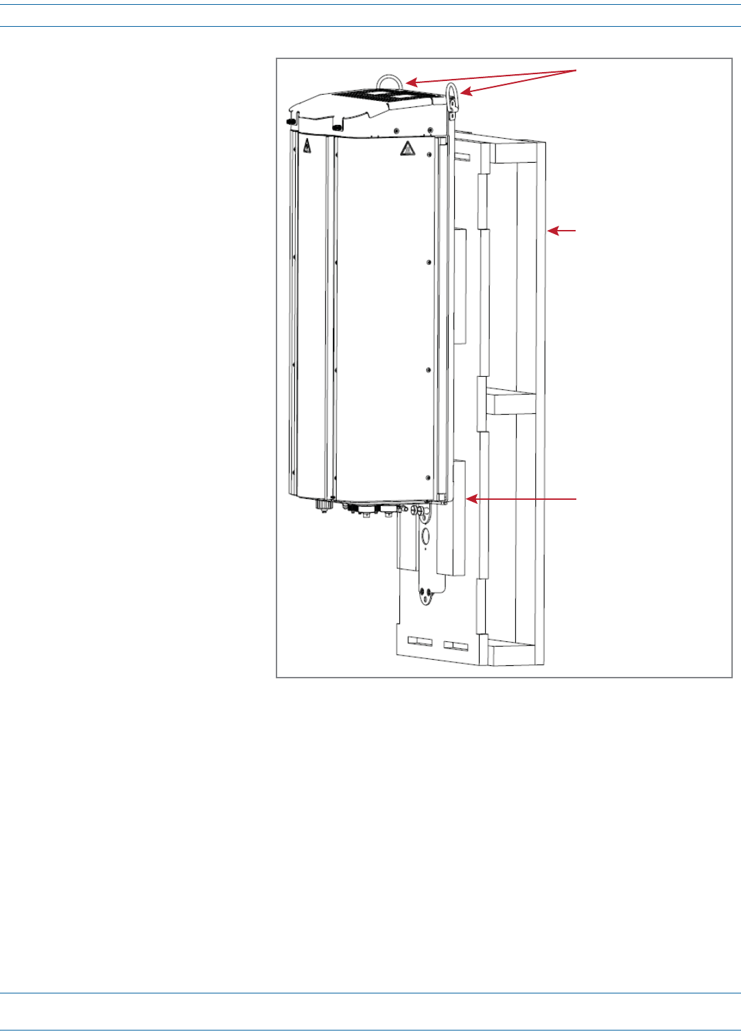
3UnpackthePRU.
aRemovethepowercableandanyothership-a-longitemsfromeithersideofthePRU.
bConnectahoisttothetwoDringsatthetopofthePRU.
Top of a
Dual-Bay PRU
D-Rings on
the PRU
FlexWave® Prism Remote Unit and RF Module Installation Guide FWPP-504-02
Page 40 © May 2017 CommScope, Inc.
Install the Prism Remote Unit
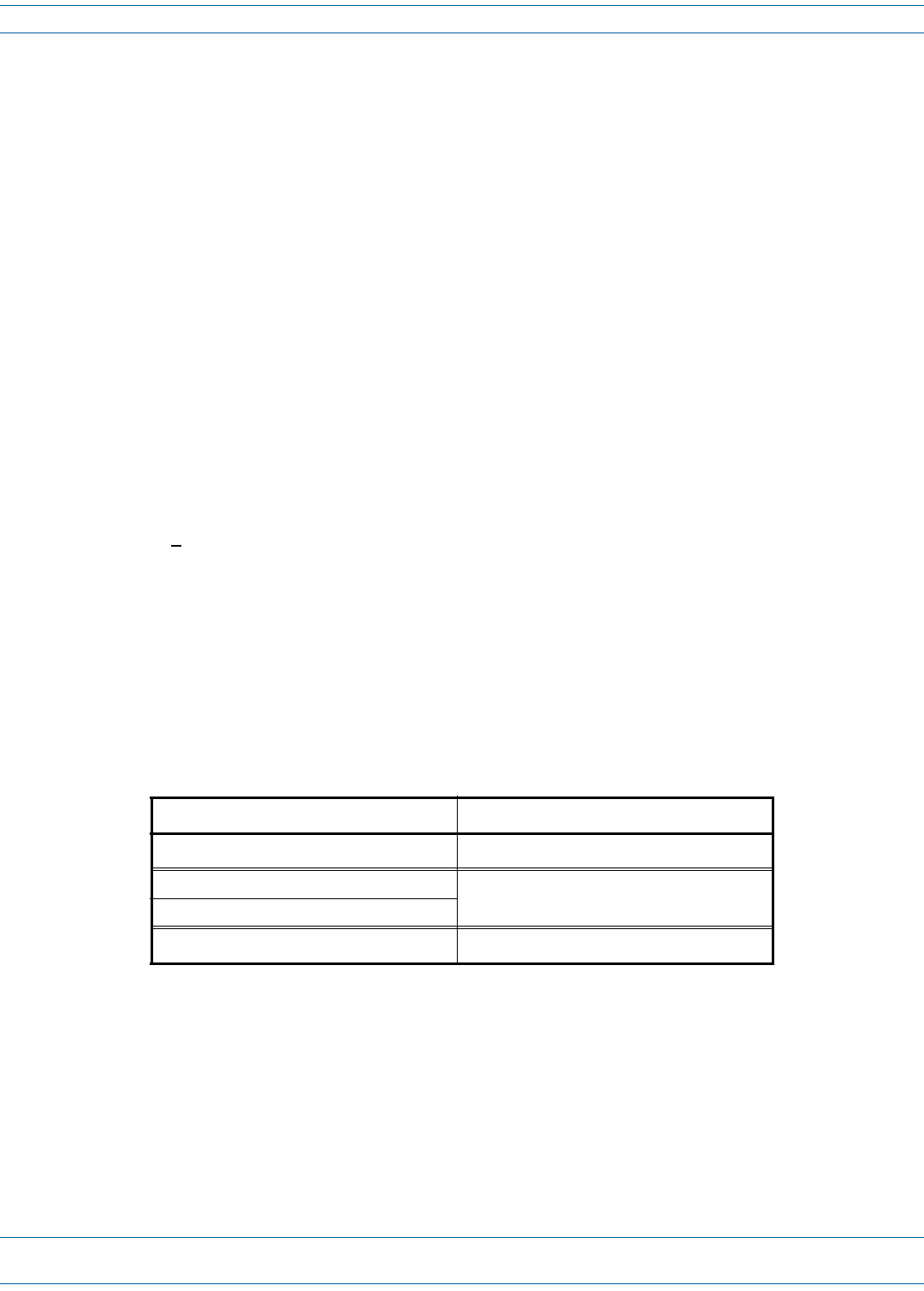
cLoosenthetwocaptivescrewsatthebottomofthePRU.
Boom of the PRU
Capve screws on the PRU
Install the Prism Remote Unit
FWPP-504-02 FlexWave® Prism Remote Unit and RF Module Installation Guide
© May 2017 CommScope, Inc. Page 41
dHoistthePRUtoanupright
positionandtapthecrate
downwardstoseparatethe
PRUfromtheMounting
Bracket.
eRemovetheMounting
Bracketfromthecrate:
iUnscrewtwoboltsand
removetheMounting
Bracketfromthecrate.
ii SavetheMounting
Bracketforfield
installation.
iii Savethetwoboltsand
emptyshippingcratefor
useshouldthe
equipmentrequire
shipment.
CAUTION! The crate used to ship the
Fullband Remote Unit
and the two bolts used to
fasten the Mounting
Bracket to the shipping
crate are not intended for
use for when mounting
the PRU in the field.
Hoist should be connected
to the two D-Rings on the
top of the PRU chassis
Tap the crate down as you
hoist the PRU chassis up
Mounng bracket will sll
be aached to the crate

FlexWave® Prism Remote Unit and RF Module Installation Guide FWPP-504-02
Page 42 © May 2017 CommScope, Inc.
Install the Prism Remote Unit
MOUNT THE PRISM REMOTE UNIT
ThePRUmaybeattachedtoautilitypole,amast,oronasolidflatsurface.Installationconsistsofsecuringthe
brackettothemountingsurfaceandthenhangingthePRUfromthebracket.Thebracketmaybeattachedtoa
varietyofsurfacessuchaswood,concrete,orsteel.
ThisguideprovidestheinformationyouneedtoinstallandusetheFlexWavePrismRemoteMountingKit.
Toensureasafeinstallation,followthestepsinthisdocumentinthefollowingorder:
1Gatherrequiredtoolsandsuppliesasdescribedin"InstallationToolsandSupplies”onpage36.
2Followtheguidelinesin"MountingPlans”onpage30todecidethebestplacetoinstallandmountthePRU.
3Familiarizeyourselfwiththe"MountingCautions”onpage42.
Mounting Cautions
ObservethefollowingcautionswheninstallingtheMountingBracketandwhenhangingaPRUonthebracket.
CAUTION! Use appropriate lifting equipment when unpacking, moving or installing the Prism Remote Unit. Do not
stand under the Prism Remote Unit as it is being hoisted into position for installation. A failure of the
lifting equipment could result in serious personal injury.
CAUTION! The pole must be structurally sound and able to support the weight of the unit being installed as listed
in Table 19 on page 31.
CAUTION! The hardware used to package the PRU for shipment is not intended for Prism Remote Unit installations
and should be kept with the Prism Remote Unit packaging. Do not use the shipping hardware when
mounting a Prism Remote Unit.
Mounting Methods
Fourinstallationmethodsareprovided,proceedtothecorrectprocedureforyourinstallationenvironment:
•"SteelPoleInstallationUsingSteelBanding”onpage43
•"PoleMountInstallationUsingBolts”onpage46
•"Wood-FramedWallMountingProcedure”onpage47
•"MasonryWallMounting”onpage49
Install the Prism Remote Unit
FWPP-504-02 FlexWave® Prism Remote Unit and RF Module Installation Guide
© May 2017 CommScope, Inc. Page 43
Steel Pole Installation Using Steel Banding
CAUTION! Always wear safety goggles when working with metal banding and when using tensioning tools.
CAUTION! This section describes how to secure a PRU to a steel pole using steel bands. In high earthquake risk
areas, CommScope advises in addition to banding, bolts should be used redundantly to ensure
mechanical mounting capable of surviving severe seismic activity. Typical areas where this attachment
method are suggested are Earthquake Risk Zone 4, per Bellcore GR-63-CORE, section 4.4.1.1. If you have
application specific questions, consult the Wireless Technical Assistance Center (TAC) for technical
assistance (see "DCCS Global Technical Support” on page 124). For information on bolting, see "Pole
Mount Installation Using Bolts” on page 46.
Stainless-steelbandsareusedtosecuretheMountingBrackettoametalpoleormastthatcannotbepiercedwith
ascreworbolt.ThenumberofbandstobeusedisdependentontheconfigurationofthePRUasdescribedin
Table20onpage36.
1Referto"MountingCautions”onpage42
beforebeginningthisprocess.
2LocatetheMountingBracketprovidedwith
thePRUMountingKitandobtainthetools
andsupplieslistedin"ToolsRequiredforAll
MountingMethods”onpage36and
"AdditionalToolsandSuppliesRequiredfor
Steel-PoleMounting”onpage36.
CAUTION! The pole must have a
diameter of at least
6 inches.
FlexWave® Prism Remote Unit and RF Module Installation Guide FWPP-504-02
Page 44 © May 2017 CommScope, Inc.
Install the Prism Remote Unit
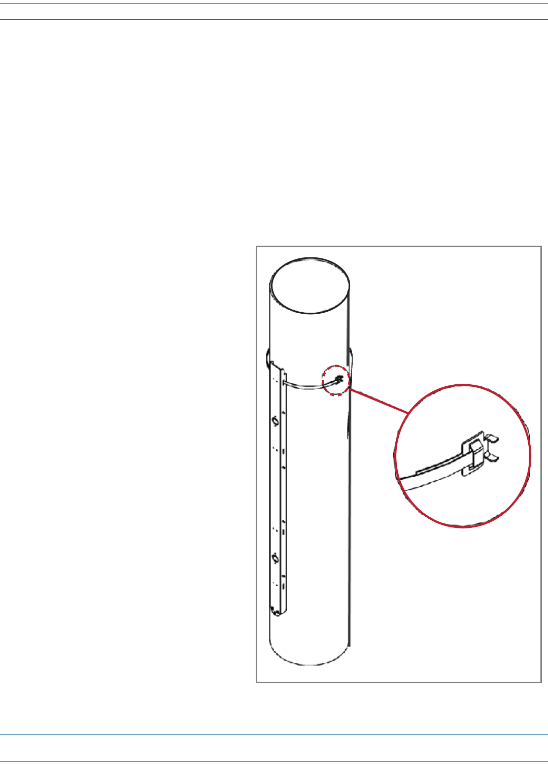
3Slideabuckleonthebandandsecurebydoublingoverunderbuckle,asshownintheillustrationbelow,or
asinstructedinmanufacturer'sinstructions.
BandsshouldpassthrougheachslotoftheMountingBracket,fromtoptobottom,ensuringthebandpasses
overthetopofthepins,asshownbelow,andagainthroughthebuckle.
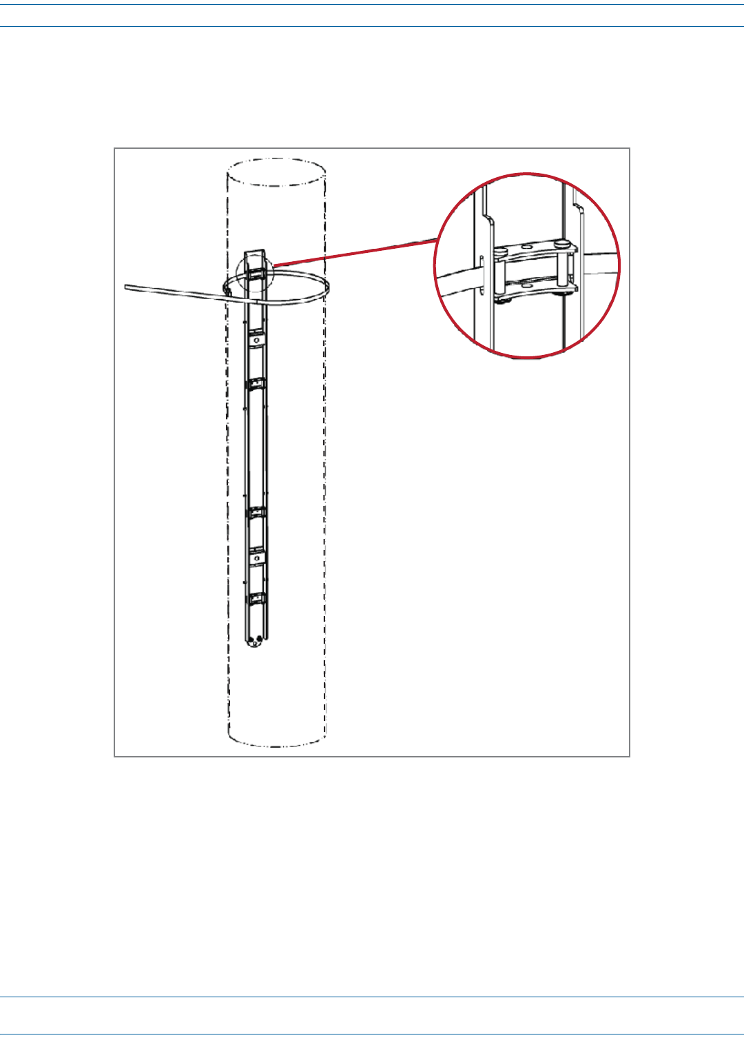
4Wrapthebandaroundpoleoncemore,passingthroughtheslotsintheMountingBracketandoverpins,and
againthroughbuckle.Doublebandingiscriticaltogeneratemaximumradialcompressionofbandingtopole
andMountingBracket.
5Followspecificmanufacturer'sinstructionsfortensioningbandstorecommendedlevels.
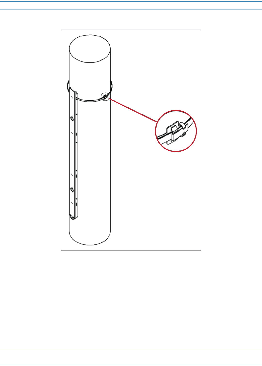
6Rolltoolover,bendingbandoveritselfatexitfromthebuckle,asshownabove,orasinstructedinthe
manufacturer'sinstructionstotemporarilysecuretensionedband.
7Cutbandusingtensioningtoolasinstructedinthemanufacturer'sinstructions.
Install the Prism Remote Unit
FWPP-504-02 FlexWave® Prism Remote Unit and RF Module Installation Guide
© May 2017 CommScope, Inc. Page 45
8Clinchbandstubinplacebyhammeringdownbuckleears,asshownbelow.
9RepeatStep3onpage44throughStep8foreachremainingbandingslotoftheMountingBracket.
10 HangthePRUfromtheMountingBracketasshownin"InstallingaPRUontheMountingBracket”onpage51.
FlexWave® Prism Remote Unit and RF Module Installation Guide FWPP-504-02
Page 46 © May 2017 CommScope, Inc.
Install the Prism Remote Unit
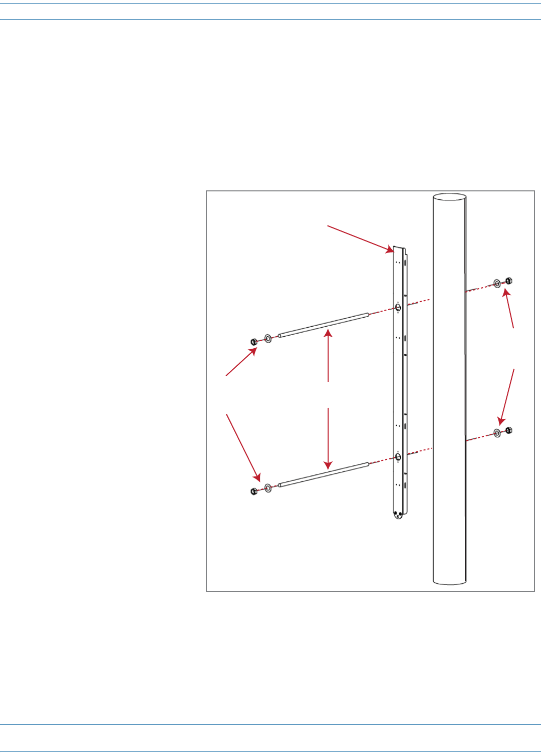
Pole Mount Installation Using Bolts
CAUTION! This section describes how to secure a PRU to a wood pole using bolts. In high earthquake risk areas,
CommScope advises in addition to bolting, banding should be used redundantly to ensure mechanical
mounting capable of surviving severe seismic activity. Typical areas where this attachment method are
suggested are Earthquake Risk Zone 4, per Bellcore GR-63-CORE, section 4.4.1.1. If you have application
specific questions, consult the Wireless Technical Assistance Center (TAC) for technical assistance (see
"DCCS Global Technical Support” on page 124). For information on banding, see "Steel Pole Installation
Using Steel Banding” on page 43.
1Referto"MountingCautions”onpage42beforebeginningthisprocess.
2LocatetheMountingBracket
providedwiththePRUMounting
Kitandobtainthetoolsand
supplieslistedin"ToolsRequired
forAllMountingMethods”on
page36and"AdditionalToolsand
SuppliesRequiredforWood-Pole
Mounting”onpage37.
3EstablishwheretheMounting
Bracketwillbemountedonthe
poleandthendeterminethe
locationofthebracketmounting
boltsonthepoleandmarkhole
locationsonpole.
4Drilla1/2-inchhole(equalto
diameterofthrough-bolt)intothe
utilitypoleatthepointsmarked
inStep3.
5Securethebrackettotheutility
poleusingtwothrough-bolts,
washers,andnutsasshowninthe
followingillustration,andthen
tightenthenutssecurely.
6Followthestepsin"Installinga
PRUontheMountingBracket”on
page51.
Pole-mounng
bracket
Through-bolts
Nuts
and
washers
Nuts
and
washers
Install the Prism Remote Unit
FWPP-504-02 FlexWave® Prism Remote Unit and RF Module Installation Guide
© May 2017 CommScope, Inc. Page 47
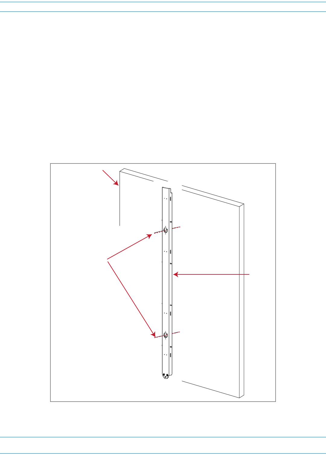
Wood-Framed Wall Mounting Procedure
1Referto"MountingCautions”onpage42beforebeginningthisprocess.
2LocatetheMountingBracketprovidedwiththePRUMountingKit.
3Obtainthetoolsandsupplieslistedin"ToolsRequiredforAllMountingMethods”onpage36and"Additional
ToolsandSuppliesRequiredforFlat-SurfaceMounting”onpage37.
4Obtainplywoodwithaminimumthicknessof0.75-inches(19.0cm)tobeusedasabackerboard.
CAUTION! If the PRU is installed in an area in which there may be moisture, use pressure-treated plywood.
5Cutthepressure-treatedplywoodtothecorrectsizetoaccommodatethePRUbeinginstalled(see
dimensionsinTable19onpage31).
6Toavoidahazardouscondition,firmlysecurethebackerboardtotheinteriorframingofthewall.
7HoldtheMountingBracketuptothewallandmarkthelocationoftheMountingBracket’stwomounting
holesontheplywoodbacker:
8Drill9/16-inchholesintheplywoodbackerattheholepositionsmarkedinStep7.
3/4-inch Plywood
Backer Board
(secure to wall studs)
Mounng
Bracket
Mark the locaon
of the two mounng
holes
FlexWave® Prism Remote Unit and RF Module Installation Guide FWPP-504-02
Page 48 © May 2017 CommScope, Inc.
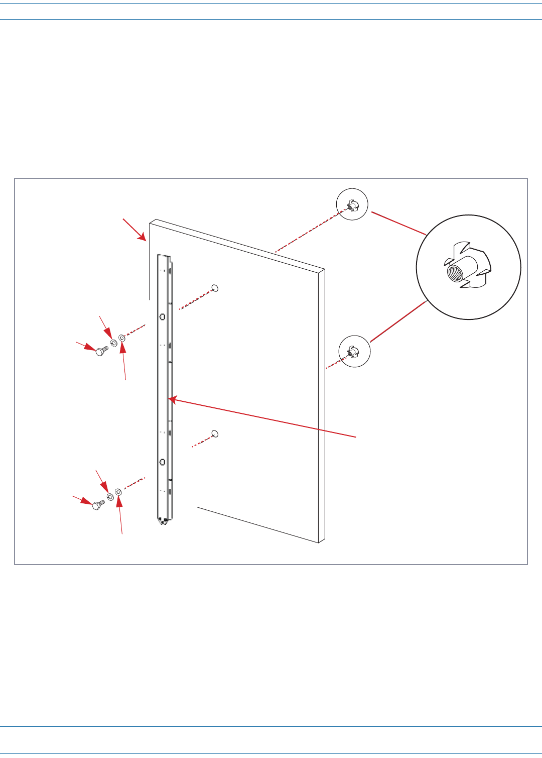
Install the Prism Remote Unit
9Refertothefollowingfigureanddothefollowing:
aFromthesideofthebackerthatwillfacethewall,drivea1/2-inchTeeNutintoeachdrilledhole.
bMounttheplywoodbackeronthewallandfirmlysecureittothewall’sinteriorstuds.
cLocatethetwo1/2x1-inchhexboltsandplacea1/2-inchlockwasherand1/2–inchflatwasheroneach
boltandthensecuretheMountingBrackettotheplywoodbackerusingtheassembledboltsandwashers.
CAUTION! If plywood backer board or supporting wall is not smooth or does not provide a flat mounting plane for
the PRU, add 1/2-inch flat washers between the Mounting Bracket and the mounting surface as
required to prevent the PRU from twisting or distorting when secured to the mounting surface.
10 HangthePRUfromtheMountingBracketasshownin"InstallingaPRUontheMountingBracket”onpage51.
Tee Nut
3/4-inch Plywood
backer board
(secure to wall studs)
1/2 x 1-1/2-inch
Hex bolt
1/2-inch Flat
washer
1/2-inch Lock
washer
1/2 x 1-1/2-inch
Hex bolt
1/2-inch Flat
washer
1/2-inch Lock
washer
Prism Remote Unit
Mounng Bracket
Install the Prism Remote Unit
FWPP-504-02 FlexWave® Prism Remote Unit and RF Module Installation Guide
© May 2017 CommScope, Inc. Page 49
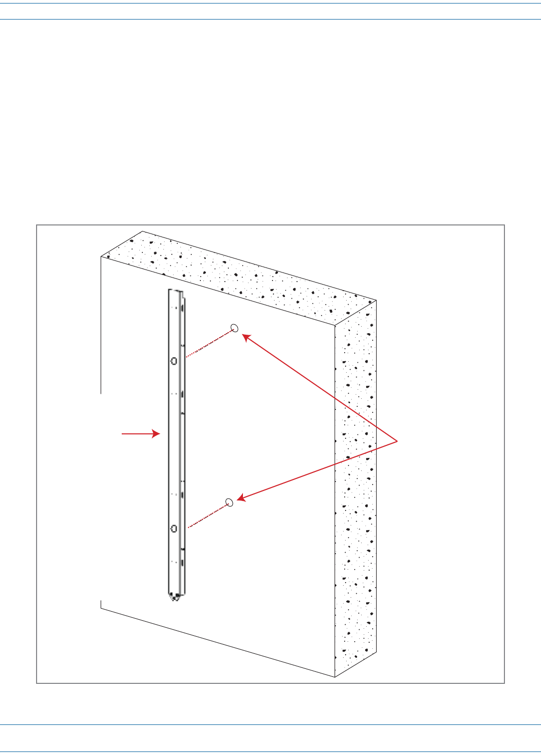
Masonry Wall Mounting
1Referto"MountingCautions”onpage42beforebeginningthisprocess.
2LocatetheMountingBracketprovidedwiththePRUMountingKit.
3Obtainthetoolsandsupplieslistedin"ToolsRequiredforAllMountingMethods”onpage36and"Additional
ToolsandSuppliesRequiredforFlat-SurfaceMounting”onpage37.
4Verifythatconcreteanchorstobeusedaredesignedfor1/2-inchbolts.
5HoldtheMountingBracketinpositiononthewall.
6Usingapencil,markthelocationofeachoftheMountingBracket’stwomountingholesonthewall.When
mountingthePRUonamasonrysurface,locatethemountinganchorsascloseaspossibletothecenterofany
bricksorblocks,especiallytheupperanchors.
Masonry Wall
Prism Remote Unit
Mounng Bracket Mark the locaon of the
two mounng holes
FlexWave® Prism Remote Unit and RF Module Installation Guide FWPP-504-02
Page 50 © May 2017 CommScope, Inc.
Install the Prism Remote Unit
7Refertoanchormanufacturer'stechnicaldatatoensureproperdrilldiametertobeused,andthendrillholes
inthewallatthelocationsmarkedinStep6.
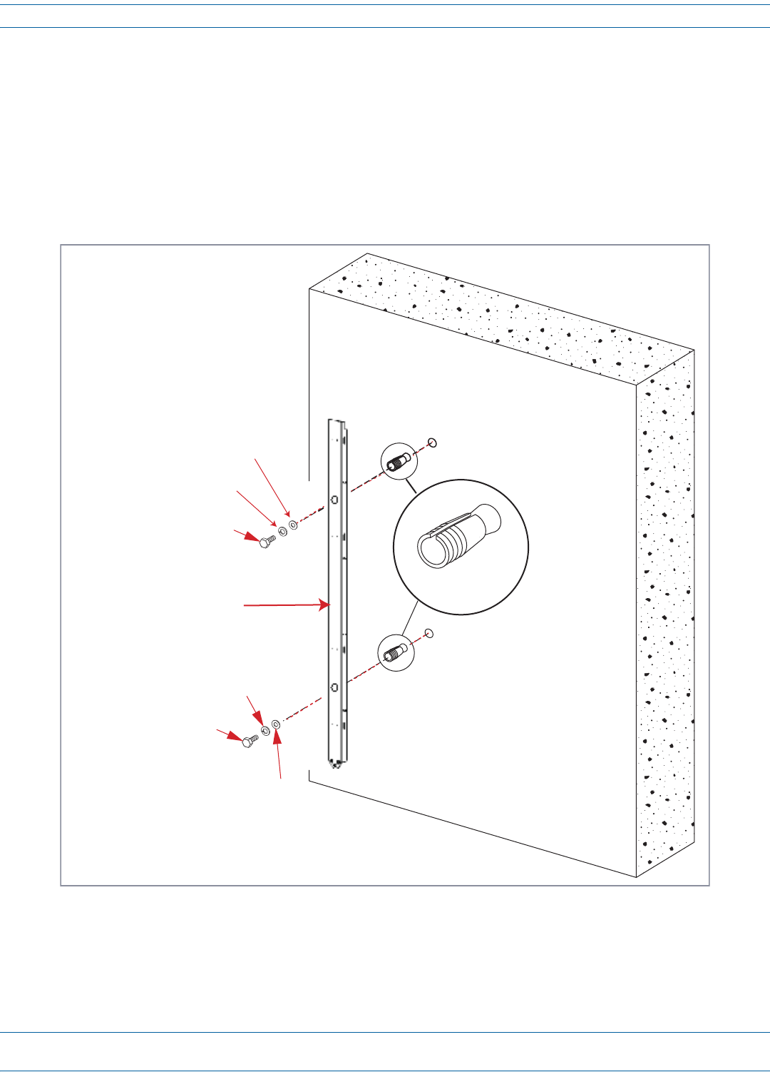
8Refertothefollowingfigureanddothefollowing:
aSettheanchorsinthewall.
bLocatethetwo1/2x1-1/2-inchmountingboltsandplacea1/2-inchlockwasherand1/2-inchflat
washeroneachbolt.
cPlacetheMountingBracketoverthetwoanchors.Threada1/2x1-1/2-inchmountingbolt(with
installedwashers)intoeachoneoftheanchors.Tightenboltsuntilsecure.
9HangthePRUfromtheMountingBracketasshownin"InstallingaPRUontheMountingBracket”onpage51.
1/2-inch flat washer
Masonry Wall
1/2-inch Concrete
anchors
1/2 x 1-1/2-inch Hex bolt
1/2-inch Lock washer
Mounng bracket
1/2 x 1-1/2-inch Hex bolt
1/2-inch flat washer
1/2-inch Lock washer
Install the Prism Remote Unit
FWPP-504-02 FlexWave® Prism Remote Unit and RF Module Installation Guide
© May 2017 CommScope, Inc. Page 51
Installing a PRU on the Mounting Bracket
ThebasicproceduretohangaPRUonaMountingBracketisthesame.Theillustrationsinthisprocedure,
however,showapole-mountinstallation.
1Referto"MountingCautions”onpage42beforebeginningthisprocess.
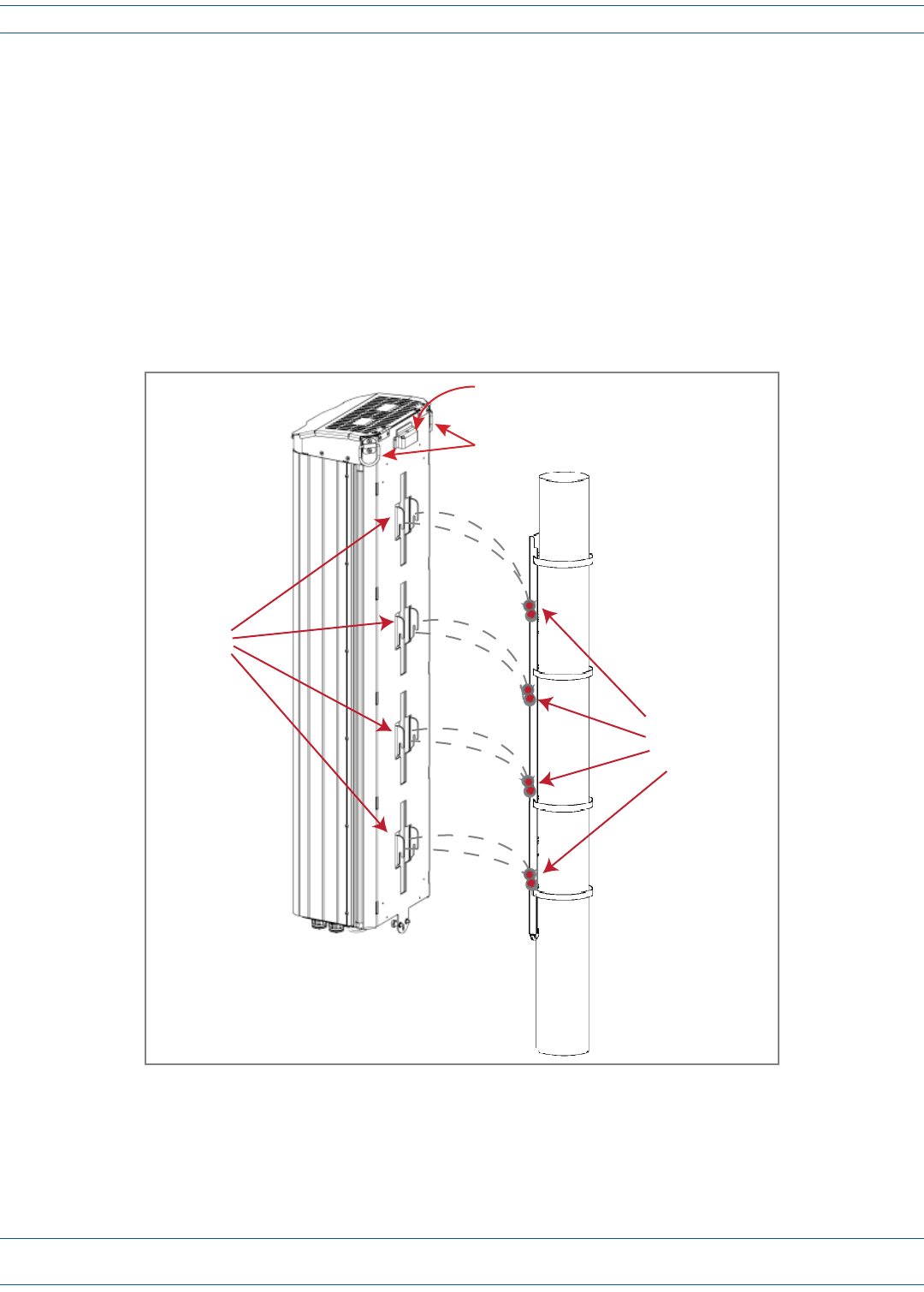
2UsetheD-RingsonthetopofthePRUtohoistthePRUintopositionforattachmenttotheMountingBracket.
CAUTION! To avoid damage to the PRU and to avoid personal injury, use appropriate lifting equipment.
3MatethemountinghooksonthebackofthePRUwiththe8horizontalhanging-bracketpinsontheMounting
Bracketasshownbelow.
4LowerthePRUuntiltheMountingCaponthetopofthePRUissnugagainstthetopoftheMountingBracket.
5Usetheflat-bladescrewdrivertosecurethetwocaptivefastenersonthebottomofthePRUtotheMounting
Bracket.
Mounng
hooks (8)
Hanging-Bracket
Pins (8)
D-Rings
Mounng Cap
FlexWave® Prism Remote Unit and RF Module Installation Guide FWPP-504-02
Page 52 © May 2017 CommScope, Inc.
Install the Prism Remote Unit
GROUND THE PRU CHASSIS
CAUTION! Avoid sharp bends in the ground wire.
CAUTION! For proper and safe equipment operation, use a #6 copper wire terminated with the provided ring
terminal to link the PRU to an earth-ground source.
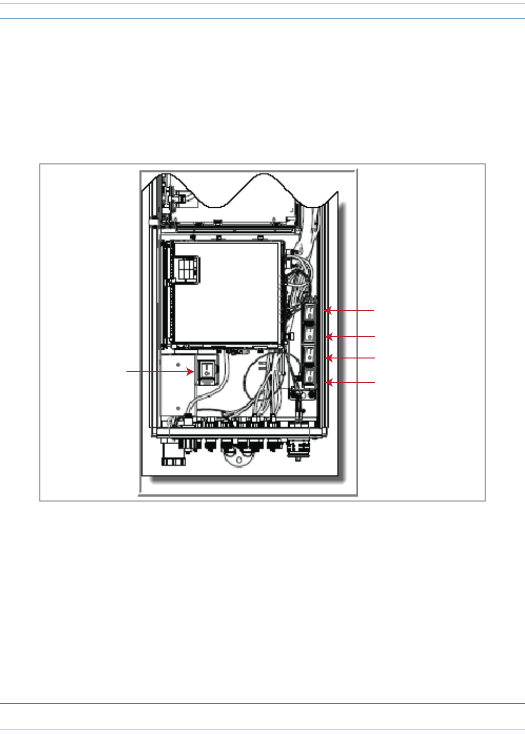
1EnsurethattheAC/DCPowerswitchtothePRUchassisandtheDCpowerswitchtoallRFModulebaysare
intheirOFFposition.
DC Power switch for Bay A
DC Power switch for Bay B
DC Power switch for Bay C
DC Power switch for Bay D
AC/DC Power switch
for PRU chassis
Install the Prism Remote Unit
FWPP-504-02 FlexWave® Prism Remote Unit and RF Module Installation Guide
© May 2017 CommScope, Inc. Page 53
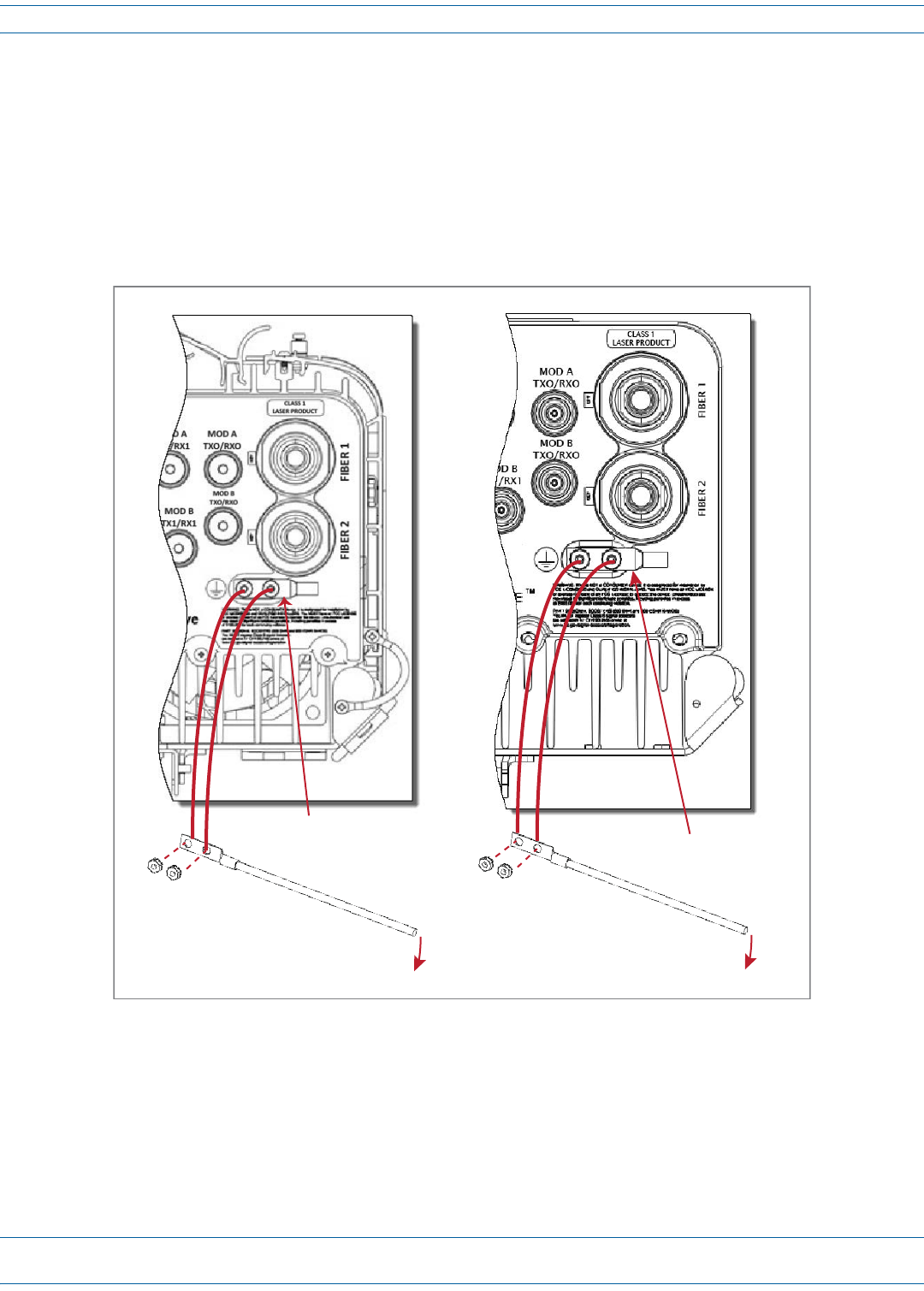
2Locatea#6AWG(4mm)coppergroundingwirelongenoughtoreachanapprovedearthground.
3Useasocketwrenchwitha3/8-inchdeepsockettoremovethetwo10-32KepsNutsfromtheDual-Ground
connectoronthebottomofthePRU.
4Securetheringterminalendofthegroundingwiretothegroundstudsontheunitusingthetwo10-32Keps
NutsremovedinStep3,andthentorquethenutsto18in-lbs±1in-lb.
5Routethefreeendofthegroundingwiretoanapprovedearthgroundsource.
6Cutthegroundwiretolengthandconnectittotheearthgroundsourceasspecifiedbylocalcodeorpractice.
To Earth Ground
Ground wire
10-32
Keps Nuts
AC-Powered PRU
Dual-Ground
connector
To Earth Ground
Ground wire
10-32
Keps Nuts
DC-Powered PRU
Dual-Ground
connector
FlexWave® Prism Remote Unit and RF Module Installation Guide FWPP-504-02
Page 54 © May 2017 CommScope, Inc.
Install the Prism Remote Unit
CONNECT A NETWORK CABLE TO THE PRU CHASSIS
ThePRUprovidesaNetworkportthatallowscommunicationswiththeinternalprocessorandaccesstotheHost
LANnetwork.Thatis,thisprovidesaLANextensiontotheHostnetwork.TheNetworkportis10/100/1000
BASE-T/TX(802.3abcompliant)MDIandrequiresaminimumofCAT5cable.
NOTE: Although the interface might provide GigE, only 100 Mbps is provided for bandwidth between the Host
and Remote.
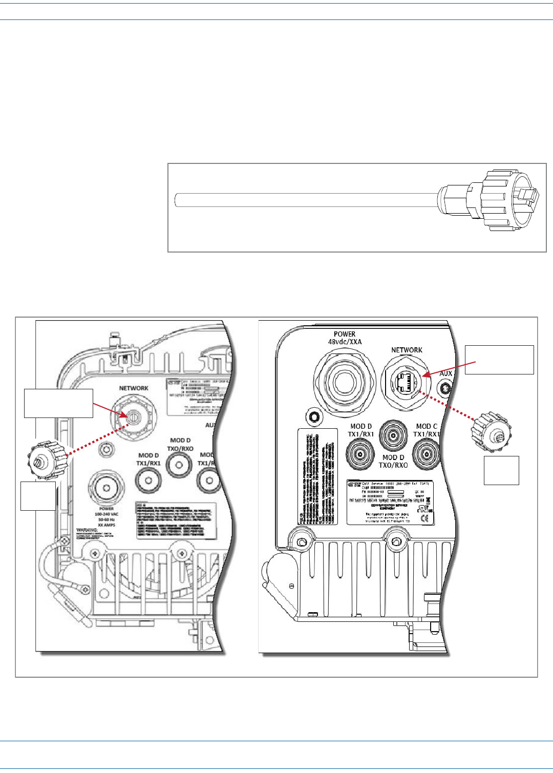
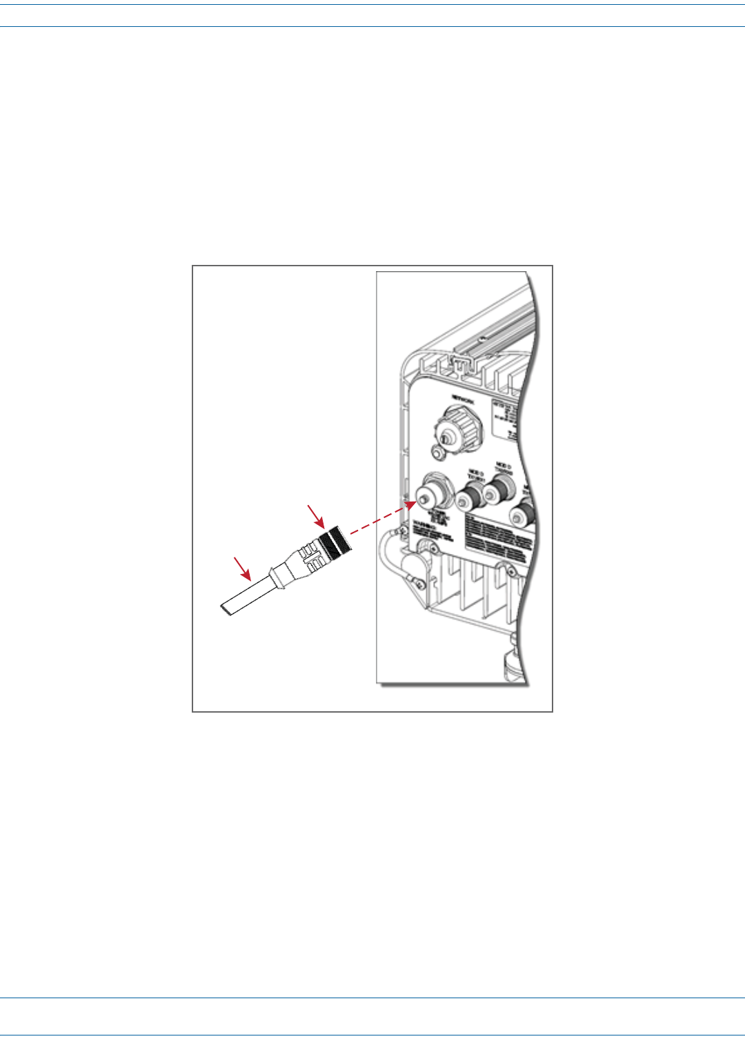
Thenetworkcablemustbe
terminatedwithahardened
RJ-45maleconnectorfor
connectiontotheNetwork
port,asshowninthegraphic
totheright.Themaximum
cablelengthis300feet(91.4
m).
UsethefollowingproceduretoinstalltheNetworkcable:
1RemovethedustcapfromtheRJ-45connectorlocatedatthebottomofthePRU.
Network cable terminated with a hardened RJ-45 male connector
RJ-45 Network
connector
AC-Powered PRU DC-Powered PRU
RJ-45 Network
connector
Dust
cap
Dust
cap
Install the Prism Remote Unit
FWPP-504-02 FlexWave® Prism Remote Unit and RF Module Installation Guide
© May 2017 CommScope, Inc. Page 55
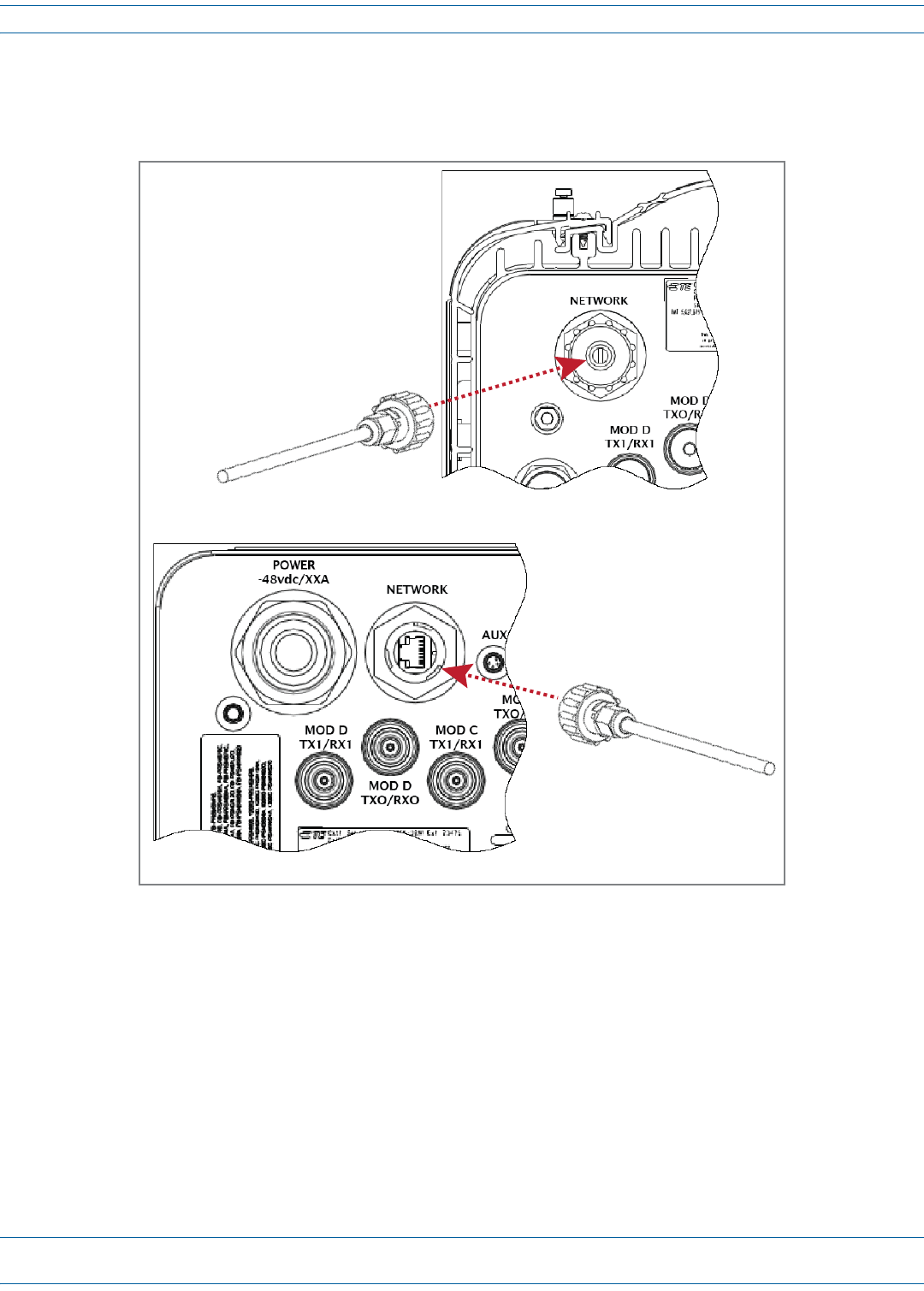
2RoutethenetworkcablefromthenetworkconnectiontotheundersideofthePRU.
3AligntheplugendoftheRJ-45cableconnectorwiththeRJ-45portreceptacleandtheninsertthecableplug
intotheportreceptacle.
4Slidetheconnectornutuptotheportuntilitengagestheconnectorlockingmechanism.
5Tightentheconnectornutinaclockwisedirection(ifnecessary,useawrenchtogriptheconnectornut)until
itsnapspasttheindentedpositionandlocksintoplace.Itmaybenecessarytoapply30to50in-lbs(3.4to
5.6Nm)oftorquetotheconnectornuttoturnitpasttheindentedposition.
DC-Powered PRU
AC-Powered PRU
FlexWave® Prism Remote Unit and RF Module Installation Guide FWPP-504-02
Page 56 © May 2017 CommScope, Inc.
Install the Prism Remote Unit
CONNECT FIBER CABLE TO THE PRU CHASSIS
TherearethreefiberconnectoroptionsforthePrismRemoteUnit;followthefibercableinstallationprocessthat
isappropriatefortheconfigurationofthePRUthatyouareinstalling:
•"OptionA:HardenedMulti-FiberOpticConnector”onpage56
•"OptionB:FiberPass-ThroughConnector”onpage62
•"OptionC:ProAxConnector(LegacyAC-PoweredPRUs)”onpage67.
Option A: Hardened Multi-Fiber Optic Connector
NOTE: Use the following procedure to install the fiber cables using a Hardened Multi-Fiber Optic Connector. If
the PRU that you are installing has a Fiber Pass-Through Connector, follow the procedure in "Option B:
Fiber Pass-Through Connector” on page 62. If the PRU that you are installing has a legacy ProAx
Connector, follow the procedure in "Option C: ProAx Connector (Legacy AC-Powered PRUs)” on page 67.
PRUsnowhaveaHardenedMulti-FiberOpticConnector(HMFOC),asshowninthepicturebelow.
AllPRUswiththeHMFOCconfigurationrequirethepurchaseofaMulti-FiberOpticCable,suchastheoneshown
below,whichallowsthePRUtointerfacewiththeOSPfiber.
Install the Prism Remote Unit
FWPP-504-02 FlexWave® Prism Remote Unit and RF Module Installation Guide
© May 2017 CommScope, Inc. Page 57
Table21identifieshowthefibersintheMulti-FiberOpticCablecorrelatetotheSeRFSFPs,whichcomepre-wired
fromthefactory.
NOTE: Each SFP utilizes a single fiber optic pair. Each SFP can support up to 12 timeslots with up to 75 MHz of
bandwidth. Each fiber connector on the PRU contains 4 fiber pairs, supporting the use of 4 SFPs. If
additional SFPs are necessary, use the second fiber connector (FIBER 2).
Table 21. Multi-Fiber Optic Cable Color Codes
Fiber Connector # Color SeRF SFP Connector Fiber Connector # Color SeRF SFP Connector
1Blue1 TX 2Blue5 TX
1Orange1 RX 2Orange5 RX
1 Green 2 TX 2Green6 TX
1Brown2 RX 2Brown6 RX
1Gray3 TX 2Gray7 TX
1White3 RX 2White7 RX
1Red4 TX 2Red8 TX
1 Black 4 RX 2Black8 RX
FlexWave® Prism Remote Unit and RF Module Installation Guide FWPP-504-02
Page 58 © May 2017 CommScope, Inc.
Install the Prism Remote Unit
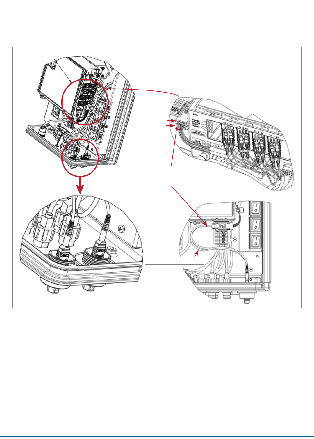
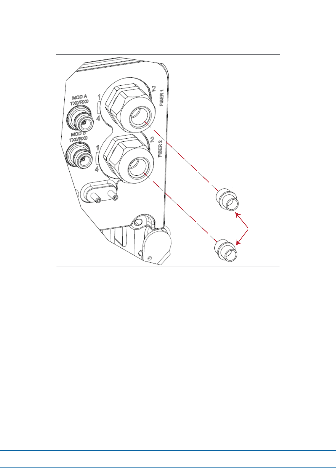
Figure13illustrateshowtheMulti-FiberOpticCablesusedwithHMFOCconnectorsrunbetweentheFiber1and
Fiber2connectorsandtheSFPs.
Figure 13. Multi-Fiber Optic Cabling
Fiber 1 and Fiber 2 Connectors
(boom of PRU)
Fiber-opc cable runs
between the Fiber 1 and Fiber 2
Connectors and the SFPs
Fiber 1 assembly
Fiber 2 assembly
Fiber 1 and Fiber 2 cable
Fiber 1 Connector
(boom of PRU)
Install the Prism Remote Unit
FWPP-504-02 FlexWave® Prism Remote Unit and RF Module Installation Guide
© May 2017 CommScope, Inc. Page 59
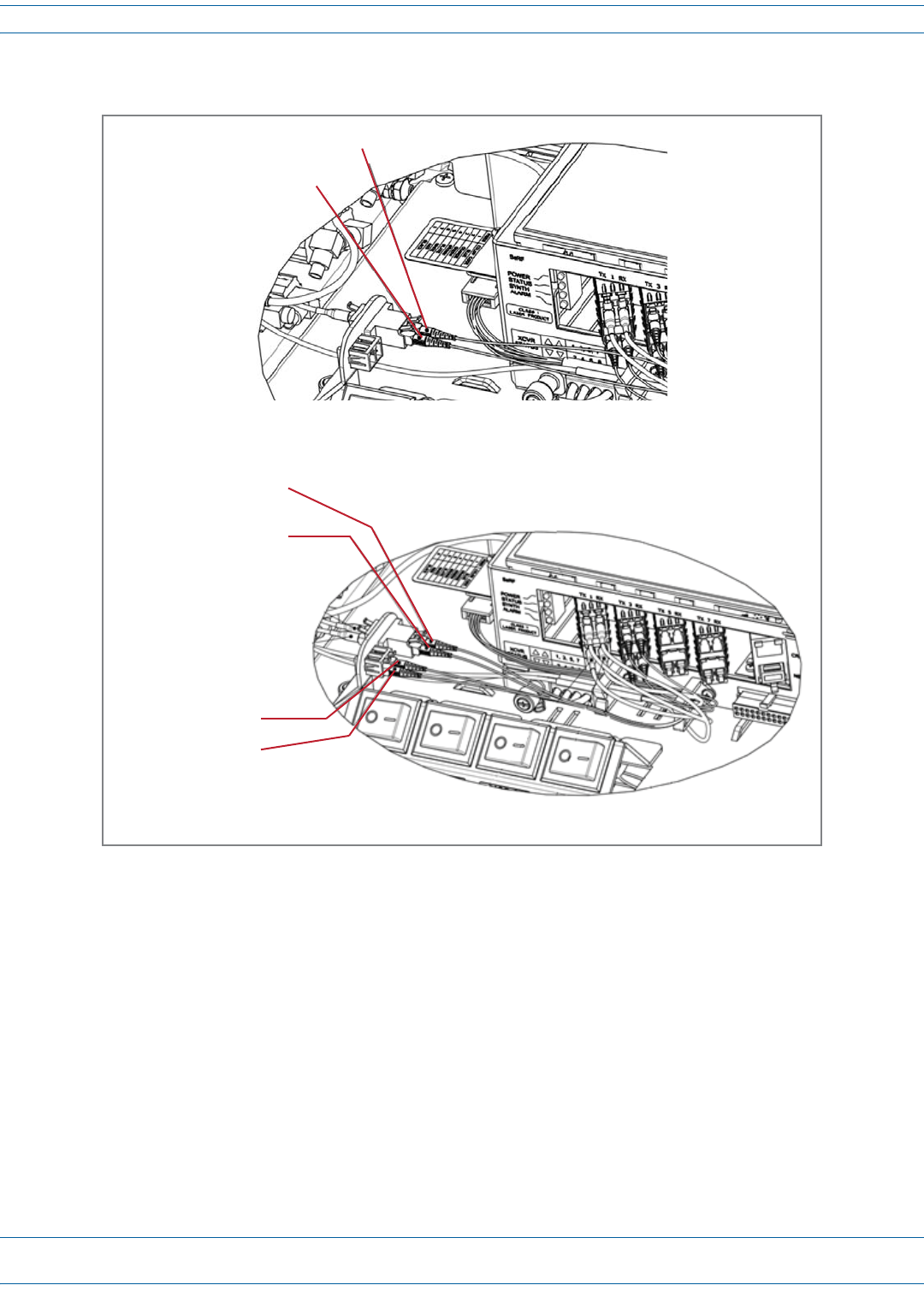
Figure14showsthecablingrequirementsforSingle-andDual-WDMunits.
Figure 14. Multi-Fiber Optic Cabling for Single- and Dual- WDM Units
1 RX - Orange
1 TX - Blue
Single-WDM HMFOC Units
1 RX - Orange
2 RX - Brown
WDM 1 Connector 1
1 TX - Blue
2 TX - Green
WDM 2 Connector 1
Dual-WDM HMFOC Units
FlexWave® Prism Remote Unit and RF Module Installation Guide FWPP-504-02
Page 60 © May 2017 CommScope, Inc.
Install the Prism Remote Unit
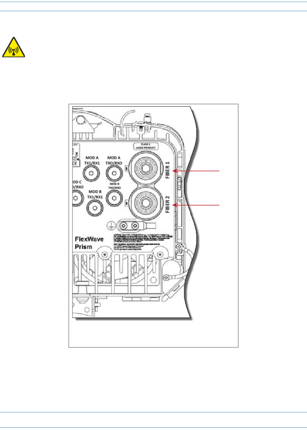
UsethefollowingproceduretoinstallthefibercablesusingtheHMFOC.
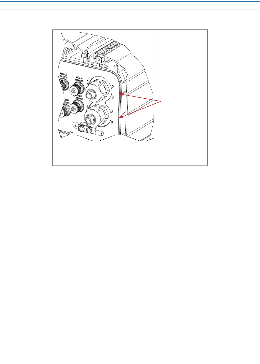
1Usea7/16”wrenchorsockettoremovethedust-covercapfromtheFiber1connector,locatedatthebottom
ofthePRU.Youneedtoturnthecapcounter-clockwiseforseveralturns.
NOTE: Do not remove the dust cover from the Fiber 2 connector until directed to do so.
CAUTION! To avoid the risk of equipment damage, ensure that the AC/DC Power switch to the Remote
Unit chassis and the DC power switch to all RF Module bays are in their OFF position before
connecting or disconnecting coaxial cables; otherwise equipment damage may occur.
AC or DC PRU
Fiber 1
Fiber 2
(The Fiber 1 and Fiber 2 connectors are in the same
locaon for both the AC- and DC-powered PRUs.)
Install the Prism Remote Unit
FWPP-504-02 FlexWave® Prism Remote Unit and RF Module Installation Guide
© May 2017 CommScope, Inc. Page 61
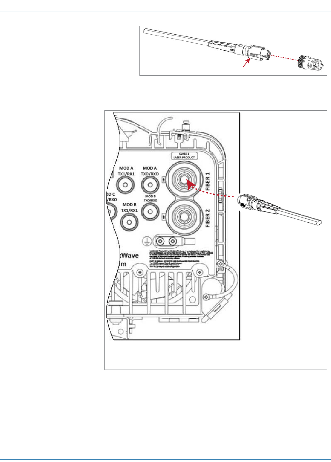
2Rotatethecouplingnutofthe
Multi-FiberOpticcable
counter-clockwisetoremoveits
dust-covercap,asshowninthe
graphictotheright.
3CleantheMulti-FiberOpticcable
connectorusingindustryapproved
cleaningprocedures.
4CleantheFiber1portusingindustryapprovedcleaningprocedure.
5InserttheMulti-Fiber
OpticcableintotheFIBER
1connector;refertothe
introductorymaterialfor
thissectionfor
informationoncabling
requirements.
aAligntheplugendof
thecablewiththekey
asindicatedonthe
overlayfortheFIBER
1connector,asshown
totheright.
bUsea9/16”wrenchto
rotatethecoupling
nutclockwise;tighten
to2-4in-lbs.
6RoutetheMulti-Fiber
Opticcablefromthe
undersideofthePRUto
theOSPbox.
7Securefibercableinplace
followinglocalpractices.
8Ifnecessary,complete
Step1throughStep7to
addasecondMulti-Fiber
OpticcabletotheFIBER2
connector.
9Continueto"Connectthe
AntennaCable”on
page71.
Coupling nut
Mul-fiber opc cable
AC or DC PRU
(The Fiber 1 and Fiber 2 connectors are in the same
locaon for both the AC- and DC-powered PRUs.)

FlexWave® Prism Remote Unit and RF Module Installation Guide FWPP-504-02
Page 62 © May 2017 CommScope, Inc.
Install the Prism Remote Unit
Option B: Fiber Pass-Through Connector
NOTE: Use the following procedure to install the fiber cables using a Fiber Pass-Through Connector.
• If the PRU that you are installing has a Hardened Multi-Fiber Optic Connector, follow the procedure
in "Option A: Hardened Multi-Fiber Optic Connector” on page 56
• If the PRU that you are installing has a legacy ProAx Connector, follow the procedure in "Option C:
ProAx Connector (Legacy AC-Powered PRUs)” on page 67.
NOTE: The graphic shown in this procedure depict an AC-powered PRU. However, the Fiber 1 and Fiber 2
connectors on a DC-powered PRU are in the same location and use the same procedure as the
AC-powered PRU to install fiber cables using a Fiber Pass-Through Connector.
UsethefollowingproceduretoinstallthefibercablesusingtheProAxconnector:
1ObtainanenvironmentallyhardenedfibercableterminatedwithLCconnectors.Theoutsidediameterofthe
cablejacketmustbebetween.035and.63inches.
2Completetheinstallationstepsin"UnpackandInspectthePrismRemoteUnitandComponents”onpage39
through"ConnectaNetworkCabletothePRUChassis”onpage54.
CAUTION! To avoid the risk of equipment damage, ensure that the AC/DC Power switch to the Remote
Unit chassis and the DC power switch to all RF Module bays are in their OFF position before
connecting or disconnecting coaxial cables; otherwise equipment damage may occur.
Install the Prism Remote Unit
FWPP-504-02 FlexWave® Prism Remote Unit and RF Module Installation Guide
© May 2017 CommScope, Inc. Page 63
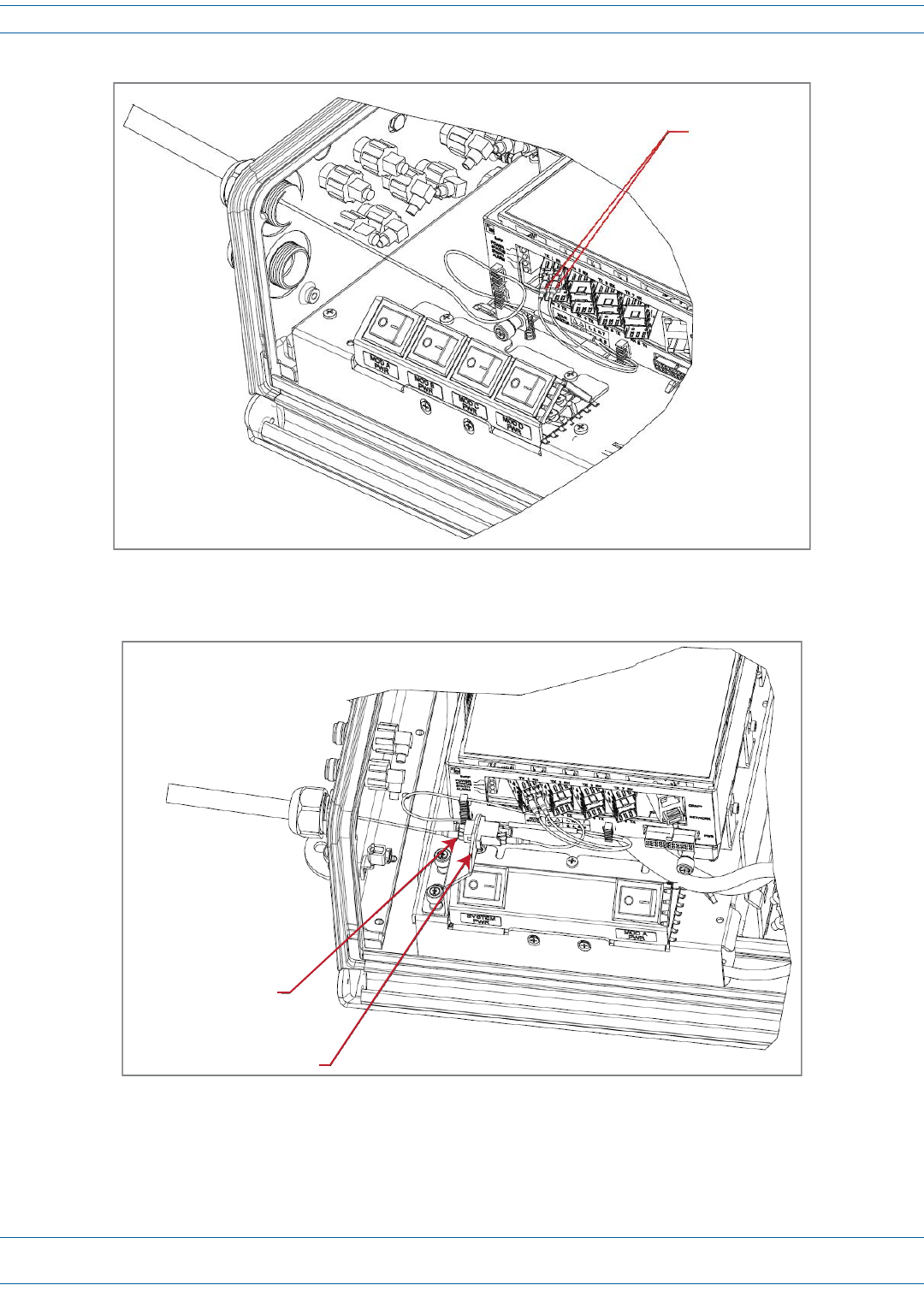
3RemoveconnectorplugonlyfromtheFiber1connector,unlessmultiplefibercablesareneeded.
NOTE: Do not remove the dust cover from the Fiber 2 connector until directed to do so.
Connector
plugs
FlexWave® Prism Remote Unit and RF Module Installation Guide FWPP-504-02
Page 64 © May 2017 CommScope, Inc.
Install the Prism Remote Unit
4InserttheFiberOpticcable,terminatedwithLCconnectors,throughtheFiber1Connector.
5CleanallLCconnectorsfollowingindustryapprovedprocedure.
6RefertooneofthefollowinggraphicstoconnecttheLCconnectorstotheSFP:
•forstandardconfigurations,seeFigure15onpage65
•forWDMPass-Throughconfigurations,seeFigure16onpage65.
Fiber 1 and Fiber 2 are
Fiber Pass-Through
Connectors
AC or DC PRU
(The Fiber 1 and Fiber 2 connectors are in the same
locaon for both the AC- and DC-powered PRUs.)
FIBER 1FIBER 2
Install the Prism Remote Unit
FWPP-504-02 FlexWave® Prism Remote Unit and RF Module Installation Guide
© May 2017 CommScope, Inc. Page 65
Figure 15. Connect LC Connector to SFP—Standard Configuration
Figure 16. Connect LC Connector to SFP—WDM Pass-Through Configuration
LC connectors
plug into the SFP
Connect a single
LC connector to the
WDM adapter
WDM bracket and adapter
FlexWave® Prism Remote Unit and RF Module Installation Guide FWPP-504-02
Page 66 © May 2017 CommScope, Inc.
Install the Prism Remote Unit
7AttachthestrengthmemberfromtheFiberOpticcabletotheStrain-Relieflugontheinsidebottomofthe
PRU.
8TightentheexternaldomenutofthePass-ThroughConnectoraroundtheFiberOpticcable—torquethe
domenutto44in-lbsplusorminus4in-lbs.
9RoutethefibercablefromtheundersideofthePRUtotheOSPbox.
10 Followlocalpracticestosecurethefibercableinplace.
11 (Optional)OneSFPsupportsupto12timeslotswith75MHzofbandwidth.Ifasecondfibercableassembly
isrequired(forexample,yourPrismsystemhasthreeSFPstohandleupto280MHzofRFbandwidth),
completeStep3onpage63throughStep10onpage66toaddthesecondfibercableassembly,onlythistime,
connecttotheFiber2connectorlocatedatthebottomofthePRUasshowninStep4onpage64.
12 Returntothemaininstallationprocessandcontinueat"ConnecttheAntennaCable”onpage71.
Strain-relief lug
Install the Prism Remote Unit
FWPP-504-02 FlexWave® Prism Remote Unit and RF Module Installation Guide
© May 2017 CommScope, Inc. Page 67
Option C: ProAx Connector (Legacy AC-Powered PRUs)
NOTE: Use the following procedure to install the fiber cables using a legacy ProAx Connector.
• If the PRU that you are installing has a Hardened Multi-Fiber Optic Connector, follow the procedure
in "Option A: Hardened Multi-Fiber Optic Connector” on page 56
• If the PRU that you are installing has a Fiber Pass-Through Connector, follow the procedure in
"Option B: Fiber Pass-Through Connector” on page 62.
NOTE: The ProAx Connector will become obsolete effective 31 May 2013, and will not be used in PRUs
manufactured after 31 May 2013.
NOTE: DC-powered PRUs do not have a ProAx connector option.
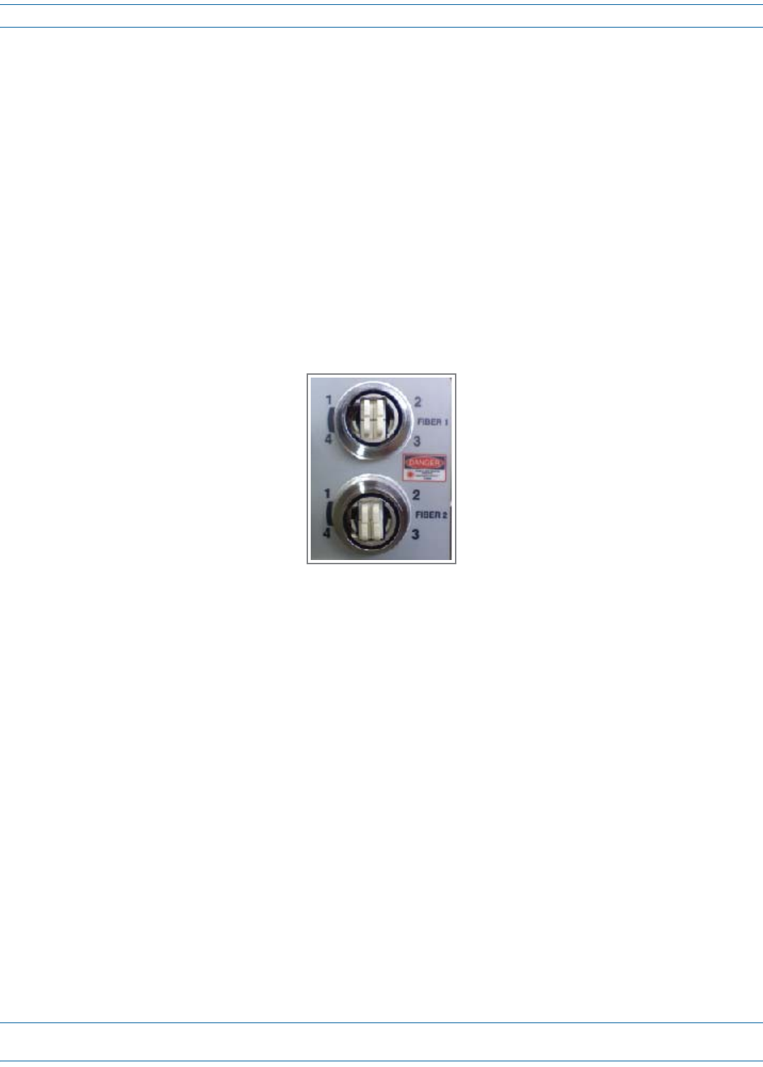
APRUwiththeProAxConnectorconfigurationrequiresthepurchaseofaProAxcableassemblyforthePrismto
interfacewiththeOSPfiber.ThefibercableconnectorisaBX.5four-portfiberconnector,asshowninthe
followingpicture:
FlexWave® Prism Remote Unit and RF Module Installation Guide FWPP-504-02
Page 68 © May 2017 CommScope, Inc.
Install the Prism Remote Unit
UsethefollowingproceduretoinstallthefibercablesusingtheProAxconnector:
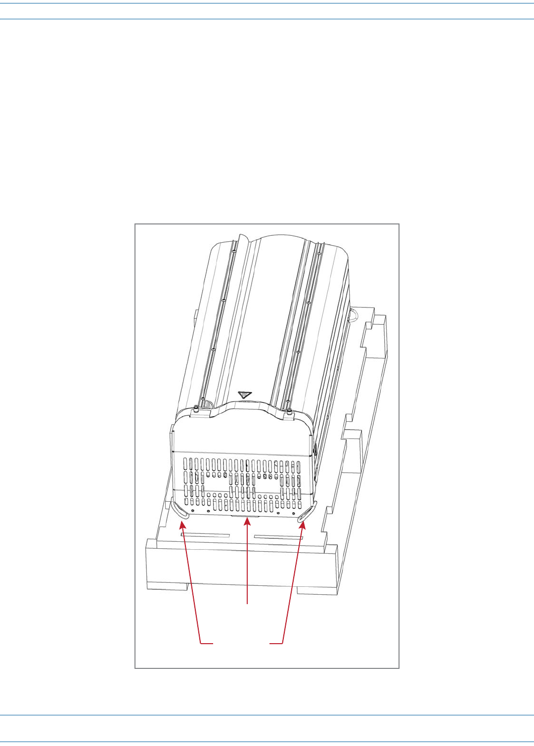
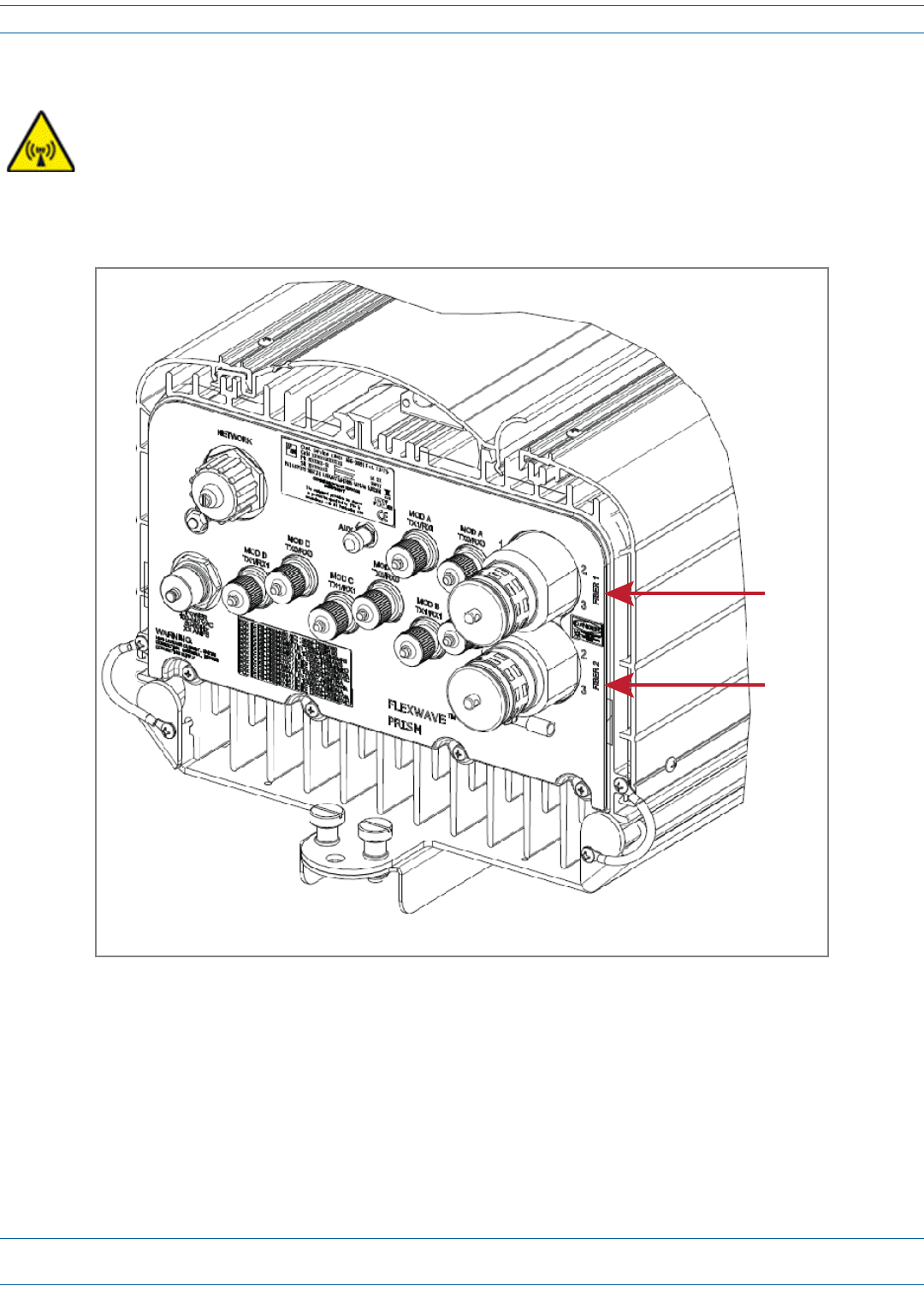
1RemoveProAxconnectordustcoverlocatedatthebottomofthePRU.
CAUTION! To avoid the risk of equipment damage, ensure that the AC/DC Power switch to the
Remote Unit chassis and the DC power switch to all RF Module bays are in their OFF
position before connecting or disconnecting coaxial cables; otherwise equipment damage
may occur.
Fiber 1
Fiber 2
Boom of Quad-Bay PRU with ProAx Connectors
Install the Prism Remote Unit
FWPP-504-02 FlexWave® Prism Remote Unit and RF Module Installation Guide
© May 2017 CommScope, Inc. Page 69
2RemovethedustcapfromthefibercableBX5connector(FIBER1).
3Cleanallfiberconnectorsfollowingindustryapprovedprocedure.
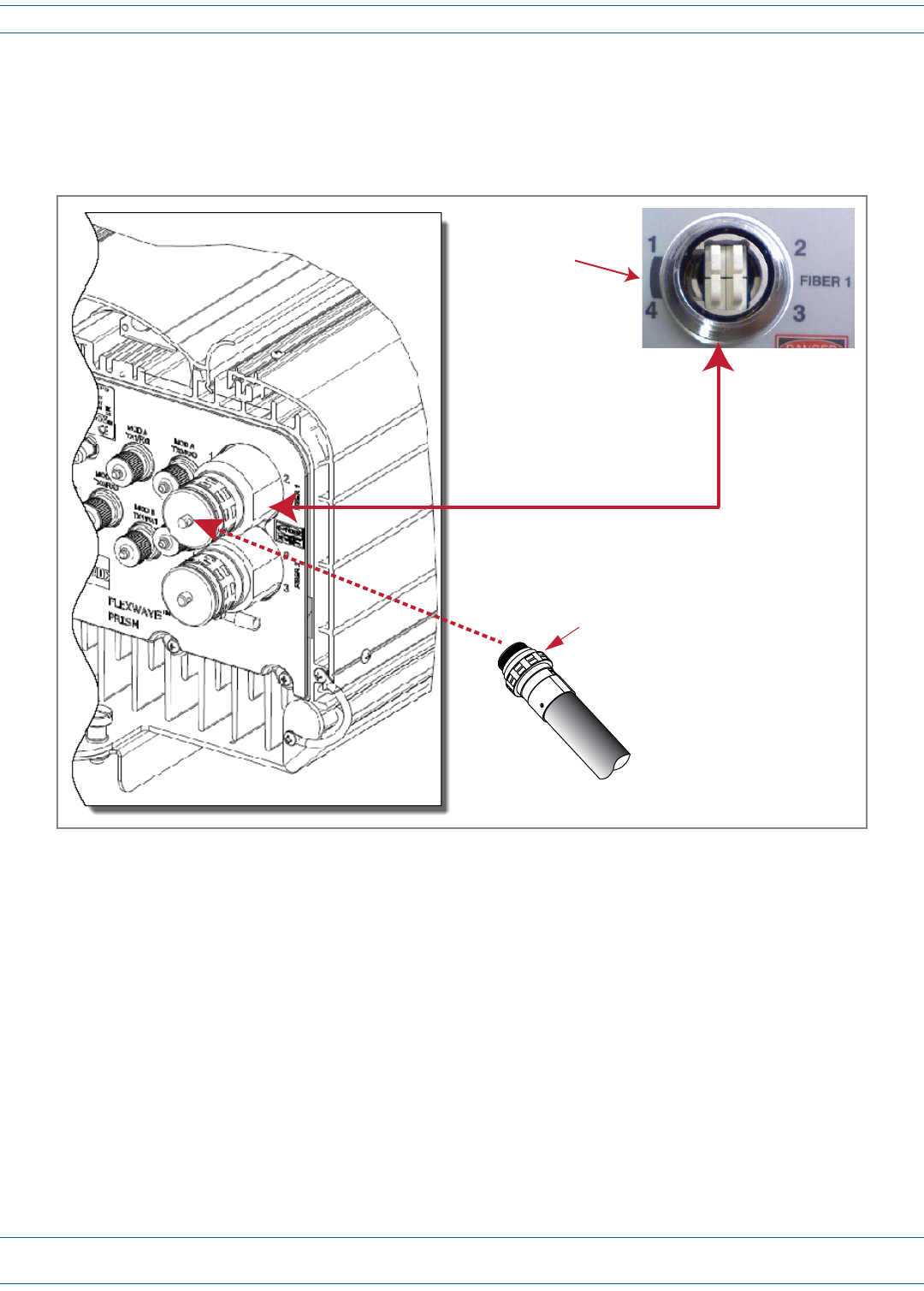
4AligntheplugendoftheBX5cableconnectorwiththeBX5portreceptacleandtheninsertthecablepluginto
theportreceptacleasshownbelow,andthenslidethestrainreliefbootovertheconnector.
Fiber 1 is a
ProAx connector
that comprises
4 BX5 connectors
Shaded area is the
Alignment Key for
the BX5 cable
connector
BX5 Cable connector
FlexWave® Prism Remote Unit and RF Module Installation Guide FWPP-504-02
Page 70 © May 2017 CommScope, Inc.
Install the Prism Remote Unit
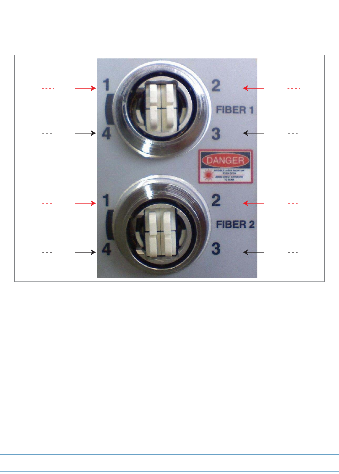
5RoutethefibercablefromtheundersideofthePRUtotheOSPbox.Observethefibernumbersandtheir
positionsinthequadcableconnectorasshownbelow.Thefibersattheotherendofthefibercableare
numberedwiththesamenumberingscheme.
6Securefibercableinplacefollowinglocalpractices.
7OneSFPequals12timeslotswith75MHzofbandwidth.Ifasecondfibercableassemblyisrequired(for
example,yourPrismsystemhasthreeSFPstohandleupto280MHzofRFbandwidth),completeStep1
throughStep6toaddthesecondfibercableassembly,onlythistime,connecttotheFiber2ProAxconnector
locatedatthebottomofthePRUasshowninStep1.
8Returntothemaininstallationprocessandcontinueat"ConnecttheAntennaCable”onpage71.
REV
Fiber 4
SFP2SFP2
SFP3SFP3 FWD
Fiber 1
SFP1SFP1 FWD
Fiber 1 SFP1SFP1
REV
Fiber 2
SFP3SFP3
REV
Fiber 2
SFP2SFP2
FWD
Fiber 3
SFP4SFP4
FWD
Fiber 3
SFP4SFP4 REV
Fiber 4
Install the Prism Remote Unit
FWPP-504-02 FlexWave® Prism Remote Unit and RF Module Installation Guide
© May 2017 CommScope, Inc. Page 71
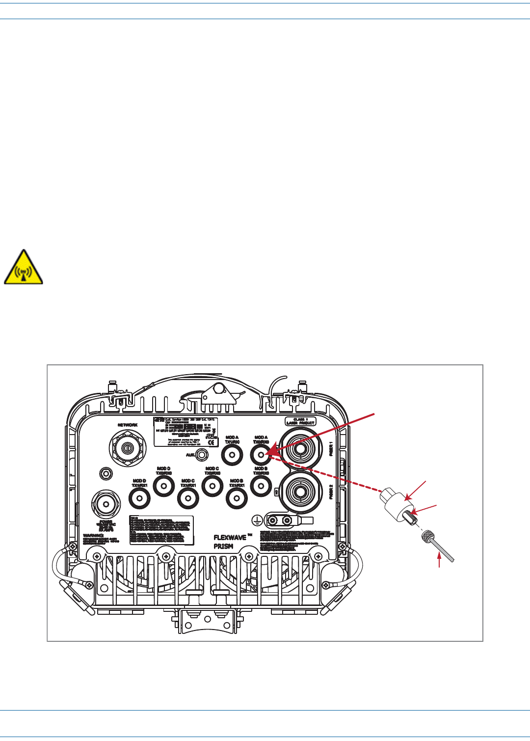
CONNECT THE ANTENNA CABLE
CoaxialantennacablesmustberoutedfromtheantennatothePRU.Thecablesmustbeterminatedwithan
N-TypemaleconnectorforconnectiontothePRUantennaportorthelightningsurgesuppressor(accessory,
requiredanytimetheantennaismountedinanareainwhichtheantennaissusceptibletoalightningstrike).
CAUTION! The antenna(s) used for this transmitter must be fixed-mounted on (outdoor/indoor) permanent
structures. RF exposure compliance is addressed at the time of licensing, as required by the responsible
FCC Bureau(s), including antenna co-location requirements of 47 CFR. 1.307(b)(3).
Usethefollowingproceduretoinstalltheantennacable(s).Thisprocedurerequiresthatyouconnectcabletoone
Antennaconnectoratatime.
1Referto"UnderstandingRFCableRules”onpage26tounderstandtherelationshipbetweenantenna
numbersandRemoteRFmodules;thisinformationmakessureyouconnecttheAntennaconnectors
correctly.
2RemovethedustcapfromanN-typefemaleAntennaconnectorlocatedontheundersideoftheunit,asshown
below.IfyouneedtoinstallcablestomorethanoneAntennaconnector,startintherearandworkforward,
applyingthecorrecttorqueasyoumakeeachconnection.Workingfromtherearportoutprovidesyouwith
thespaceyouneedtoapplythecorrecttorque.
CAUTION! To avoid the risk of equipment damage, ensure that the AC/DC Power switch to the Remote
Unit chassis and the DC power switch to all RF Module bays are in their OFF position before
connecting or disconnecting coaxial cables; otherwise equipment damage may occur.
N-type female
Antenna port
for Module A
Antenna
cable
Lightning
Surge Suppressor
(ships with RF Module)
Surge port
connector
Boom View of PRU

FlexWave® Prism Remote Unit and RF Module Installation Guide FWPP-504-02
Page 72 © May 2017 CommScope, Inc.
Install the Prism Remote Unit
3Connectalightningsurgesuppressortotheantennaport;torqueto8±1in-lbstoensurefullconnection.
NOTE: The lightning surge suppressor is included in the RF Module’s shipping container. Lightning surge
suppressor(s) are required anytime the antenna is mounted in an area in which the antenna is
susceptible to a lightning strike.
4IfthePRUhasaDual20WSMR800/PCS1900RFModule(FWP-441T841MOD),youmustinstallaFlexWave
NotchFilter(FWP-SPRINTFILTER)betweenthePRUandtheantennatoprovideprotectionfromspurious
emissionsinthePublicSafetybandbelow861.35MHzandtheCellularbandabove869.5MHz.For
informationonhowtoinstallaNotchFilter,goto"FlexWaveNotchFilter(FWP-SPRINTFILTER)”onpage114.
5Ensurethatthechassisgroundwireisinstalledcorrectly(see"GroundthePRUChassis”onpage52).For
maximumprotection,thesystemgroundwiremustbeattachedtoalowimpedancegroundsystem.
6RoutethecoaxialantennacablefromtheantennatotheundersideofthePRU.
7CuttheantennacabletotherequiredlengthandterminatewithanN-typemaleconnector.
8Connecttheantennacabletothelightningsurgesuppressorortotheantennaport;apply15in-lbs(1.7Nm)
oftorque.
CAUTION! The antenna cable connections must be weather proofed (sealed) for outdoor installations.
9RepeattheStep2throughStep8fortheremainingantennacables.
DETERMINE THE CIRCUIT BREAKER OR FUSE FOR THE PRU
UsetheinformationinthissectiontodeterminethecircuitbreakerorfusethatshouldbeinstalledintheAC
circuitbreakerboxortheDCPowerSourceDistributionPanel:
•AnAC-poweredPRUsupportspowerinputfroma90to240Vacpowersupply.
•ADC-poweredPRUsupportspowerinputfroma-40to-60Vdcpowersupply.

Install the Prism Remote Unit
FWPP-504-02 FlexWave® Prism Remote Unit and RF Module Installation Guide
© May 2017 CommScope, Inc. Page 73
Power Consumption
1Calculatethemaximumpowerconsumption,whichdeterminesthecircuitbreakerorfusetouse.
aReviewthePRUordertodeterminethenumberofDARTs,numberofpowersupplies,andthenumberof
SFPs.UsethisinformationtofindthepowerconsumptionfromTable22andTable23onpage75.
bEnterthepowerconsumptioninthespacesprovidedbelow.
cAddtheWattsandenterthetotalintheTotalPowerConsumptionfield.
2DividethetotalWattsbytheinputVoltagetodeterminethecurrent(Amperes)requirements:
TotalWatts/InputVoltage=Amps
3Determinethecircuitbreakerorfusesizebasedonlocalcodesandpractices.
CAUTION! Circuit breaker or fuse size must be 20 Amps or less to protect the internal wiring of the PRU.
SeRFModulepowerconsumptionfromTable22 _________Watts
AdditionalSFPs_____x1.25W _________Watts
RFModulepowerconsumptionfromTable23onpage75 _________Watts
TotalPowerConsumption _________Watts
FlexWave® Prism Remote Unit and RF Module Installation Guide FWPP-504-02
Page 74 © May 2017 CommScope, Inc.
Install the Prism Remote Unit
Power Consumption Tables
ThePRUpowersuppliesare>80%efficient,bothACandDCversions.ThedatainTable22andTable23on
page75andthepower-supplyefficienciescanbeusedtoestimatetheinputcurrentforagivenPRU
configuration.Usethefollowingequationtocalculatetheinputcurrentdraw:
Input Current = (Total Power Consumption / 0.80) / Input Voltage
Forexample,foraPRUwith1SeRFModule,1SFP(36WTypical,38WMax),andasingle20W850/1900HDMRF
Module(250WTypical,330WMax),thentheTotalPowerConsumptionwouldbe286W(Typical)and368W
(Max).Therefore,fora110VACinput,thecurrentestimatewouldbe3.25amps(Typical)and4.18amps(Max).
Table 22. SeRF Module Power Consumption
SeRF Module
Power Consumption per Module
Nominal (W) @ 25C Maximum (W)
SeRF Module (1 SFP) [add 1.25W for each SFP added] 36 38

Install the Prism Remote Unit
FWPP-504-02 FlexWave® Prism Remote Unit and RF Module Installation Guide
© May 2017 CommScope, Inc. Page 75
Table 23. Power Consumption by RF Module
Prism RF Module Description
Power Consumption Per Module
Nominal (W) @ 25C Maximum (W)
Single or Dual
SuperDART RF
Module
20W 1900 PCS, 20W 2100AWS, 700 LTE Non-Diversity 299 368
40W 700 LTE Non-Diversity 299 368
40W 1900 PCS, 40W 2100 AWS (Dual AMPs) Non-Diversity 568 706
10W GSM900 (Includes EGSM, PGSM, APAC, GSM)
Non-Diversity 299 337
Diversity 321 359
15.8W GSM1800
Non-Diversity 299 337
Diversity 321 359
15.8W 2100UMTS
Non-Diversity 299 337
Diversity 321 372
HDM RF Modules
40W 850 Cell SISO HDM SISO - Non-Diversity 249 315
40W 1900 PCS SISO HDM SISO - Non-Diversity 249 315
40W 2100 AWS SISO HDM SISO - Non-Diversity 249 315
20W 700 MIMO LTE HDM (LABC or uC) MIMO - Non-Diversity 250 330
20W 1900 PCS MIMO HDM MIMO - Non-Diversity 250 330
20W 2100 AWS MIMO HDM MIMO - Non-Diversity 250 330
20W 2100 AWS-3 MIMO MIMO - Non-Diversity 250 330
20W 1900 PCS MIMO HDM MIMO - Non-Diversity 250 330
20W 800 SMR MIMO HDM MIMO - Non-Diversity 250 330
20W 850 Cell MIMO HDM MIMO - Non-Diversity 250 330
20W 850/1900 HDM Dual HDM - Non-Diversity 250 330
20W 700 LABC/700 uC Dual HDM Dual HDM - Non-Diversity 250 330
20W 800/1900 HDM Dual HDM - Non-Diversity 250 330
20W 1900/2100 HDM Dual HDM - Non-Diversity 250 330
20W 2500 TDD Low HDM MIMO - Non-Diversity 250 330
20W 2500 TDD High HDM SISO - Non-Diversity 175 230
Classic DART RF
Module
20W 1900 PCS or 2100 20W AWS
Non-Diversity 292 358
Diversity 314 381
6.5W 800/900 ESMR Non-Diversity 195 196
40W 850 Cell Non-Diversity 299 368
20W 850 CELL
Non-Diversity 271 327
Diversity 293 350
FlexWave® Prism Remote Unit and RF Module Installation Guide FWPP-504-02
Page 76 © May 2017 CommScope, Inc.
Install the Prism Remote Unit
CONNECT THE POWER WIRING
ThePRUsupportsbothACandDCpower.Followthestepsappropriatetoyoursystemconfiguration:
•"Option1:ConnecttheACPowerWiring”onpage76
•"Option2:ConnecttheDCPowerWiring”onpage79.
Option 1: Connect the AC Power Wiring
A15-foot,3-wirecablewithconnectorsisprovidedfortheACpowerconnections.Theconnectorendofthecable
connectstotheACpowerportlocatedonthebottomoftheunit.Thestubendofthecablemustberoutedtoan
externaljunctionbox(notprovided)forpermanentconnectiontotheACpowersystemwiring.Ifthecablemust
beterminatedwithaplugtoconnecttotheACadapter,theplugmustbeprovidedbytheinstaller.
TheACpowersourcemustsupplybetween100and240Vac,50or60Hz,single-phasepowerthroughacircuit
breakerorfuse.TheACpowercableprovidesthreewireleadsforline,neutral,andgroundconnections.The
powercableisratedforindoororoutdooruseandmustnotbeplacedwithinelectricalconduitasthiswill
impedethecoolingofthecableduringusage.Theelectricaljunctionboxandanyconduit,wire,andfittings
requiredmustbeprovidedbytheinstaller.
CAUTION! Use extreme caution when working with high voltage AC power. Ensure all power is disconnected
before working on power circuits.
NOTE: All electrical work must comply with local codes and requirements. A locally licensed electrical
contractor is best qualified to perform this work. For additional information, consult with the
CommScope Technical Support for Wireless Products team (see "DCCSGlobalTechnicalSupport”on
page124).
UsethefollowingproceduretoinstalltheACpowerwiring:
1Usetheinformationin"DeterminetheCircuitBreakerorFuseforthe
PRU”onpage72toensurethatthecorrectcircuitbreakerorfuse
requiredforthisinstallationisinstalledinthecircuitbreakerpanel.
2LocatetheACpowercablethatisprovidedseparatelywiththePRU.
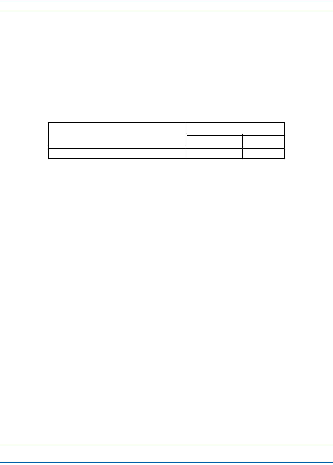
3RoutethepowercablebetweentheACpowerport,locatedonthe
undersideofthePRUandthenearestACpowerjunctionboxasshown
inthegraphictotheright.Itmaybenecessarytoinstallanewjunction
boxifanexistingjunctionboxisnotavailable.
4SecurethecablebetweentheACpowerportandtheACpowerjunction
boxperlocalpractice.Leavesufficientslackinthecabletoallowittobe
easilyconnectedanddisconnectedfromtheACpowerport.
NOTE: The power cable is rated for indoor or outdoor use and must not
be placed within electrical conduit as this will impede the cooling
of the cable during usage. The cable run distance to the AC power
source must not exceed 100 feet.
Remote enclosure
AC power juncon box
AC power cable
AC power wires routed
to circuit breaker panel
Install the Prism Remote Unit
FWPP-504-02 FlexWave® Prism Remote Unit and RF Module Installation Guide
© May 2017 CommScope, Inc. Page 77
5InstallanyACpowersupplywiresthatmayberequiredbetweentheACjunctionboxandtheACcircuit
breakerbox.
NOTE: It is recommended that an AC outlet be installed near the PRU for powering tools and test equipment.
This outlet must include a GFCI device for protection.
NOTE: An appropriate disconnect device, as well as branch circuit protection, must be provided as part of the
installation.
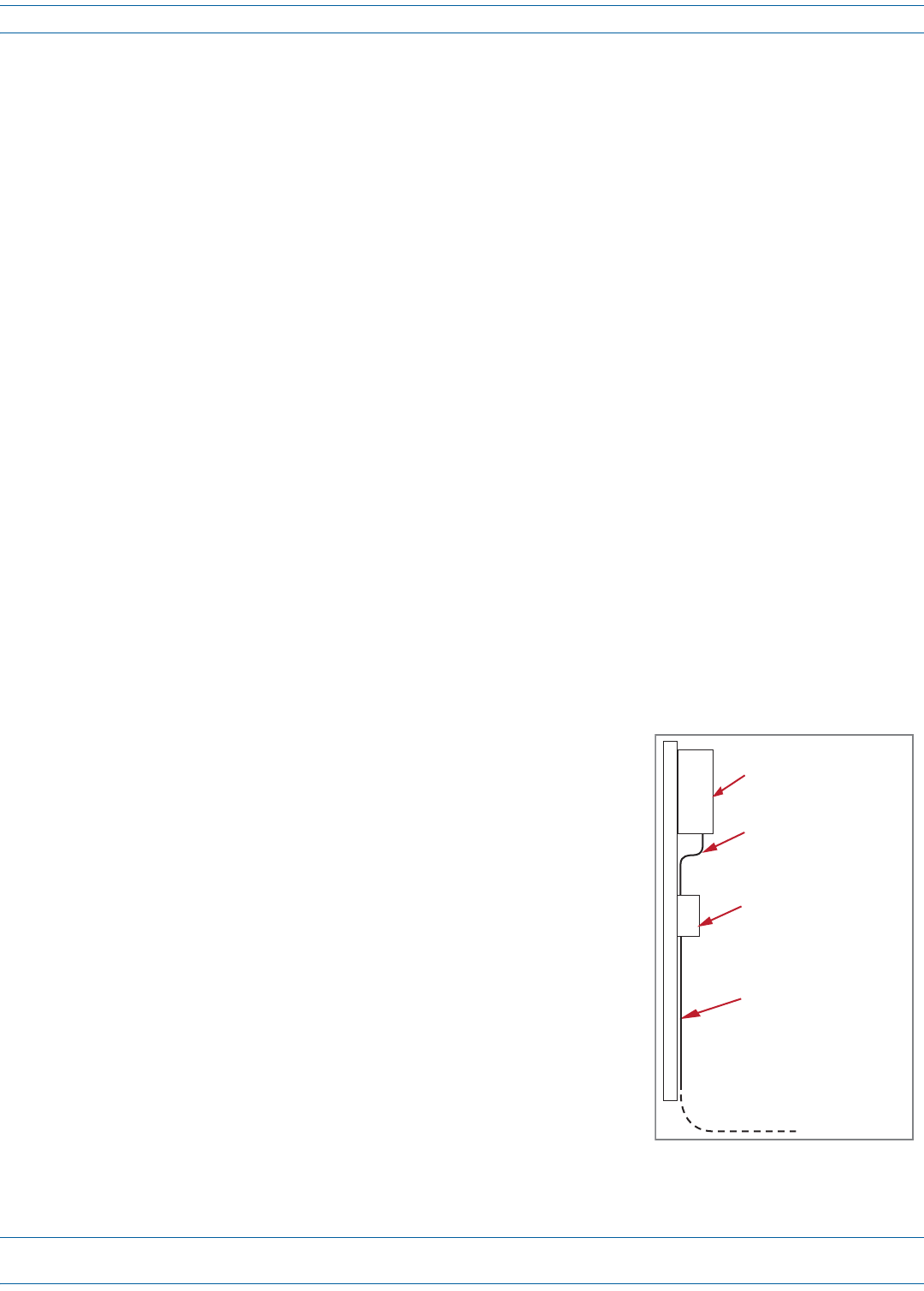
6ConnecttheACpowercable
wirestotheACpowersupply
wires.Refertothegraphicto
therighttoidentifythecolor
codeandwiredesignations;
usethealignmentkeyto
ensurethatthecable
correctlyalignswiththe
connector.Ifthecableisnot
alignedcorrectlywiththe
connector,connectorpins
maybedamaged.
7AttheACbox,connecttheAC
powersupplyloadwirestoa
circuitbreakerorfuse.
CAUTION! For proper and safe
equipment operation,
an approved earth ground connection must be provided and maintained.
8Connectthegroundwiretoanapprovedearthground.
9PlacethecircuitbreakerintheONpositionandthentesttheconnectorendoftheACpowercableforproper
voltagelevelsandcorrectpolarity.
10 Whentestingiscomplete,placethecircuitbreakerintheOFFposition.
M16 Connector
3 Black1 White
Female-End View
2 Green
Alignment key
FlexWave® Prism Remote Unit and RF Module Installation Guide FWPP-504-02
Page 78 © May 2017 CommScope, Inc.
Install the Prism Remote Unit
11 RemovethedustcapfromtheACpowerportlocatedonthebottomofthePRUasshownbelow.
CAUTION! While trying to connect the AC power cable to the PRU AC power port, it is possible for the line terminal
on the cable connector to contact the ground pin on the power port. If the AC cable is energized, this
will result in a direct short to ground for the AC power. To avoid possible personal injury and equipment
damage, always turn the AC power off before connecting the AC power cable to the AC power port.
12 ConnectthepowercableconnectortotheACpowerport;usethealignmentkeytoensurethatthecable
correctlyalignswiththeconnector.Ifthecableisnotalignedcorrectlywiththeconnector,connectorpins
maybedamaged.
13 Tightenthecouplingnutonthepowerconnector.
14 Dooneofthefollowing:
•IfyouneedtoinstallanRFModule,goto"InstalltheRFModule(s)”onpage84.
•IftheRFModulesrequiredforthisinstallationarealreadyinstalledinthePRU,goto"PowerontheRF
Module(s)andthePrismRemoteUnit”onpage110.
Boom of PRU
Coupling nut
Power cable
Install the Prism Remote Unit
FWPP-504-02 FlexWave® Prism Remote Unit and RF Module Installation Guide
© May 2017 CommScope, Inc. Page 79
Option 2: Connect the DC Power Wiring
NOTE: All electrical work must comply with local codes and requirements. A locally licensed electrical
contractor is best qualified to perform this work. For additional information, consult with the
CommScope Technical Support for Wireless Products team (see "DCCSGlobalTechnicalSupport”on
page124).
1Usetheinformationin"DeterminetheCircuitBreakerorFuseforthePRU”onpage72toensurethatthe
correctcircuitbreakerorfuserequiredforthisinstallationisinstalledintheDCPowerSourceDistribution
Panel.
2ObtainaDCpowercablethatmeetsthefollowingrequirements:
•TheDCpowercablecanbe8AWGor6AWG,3-or4-conductorpowercableratedforoutdooruse.
•Thewirecolorsmustbegreen,red,andblack.
•Thecablediametermustbe.71to.98inches.
•Ifa4-conductorpowercableisused,theextraconductorcanbesnippedoffbeforeinstallation.
•Ifusing6AWGwire,theinstallermustprovideanduse#10studsize,6AWGringterminals.
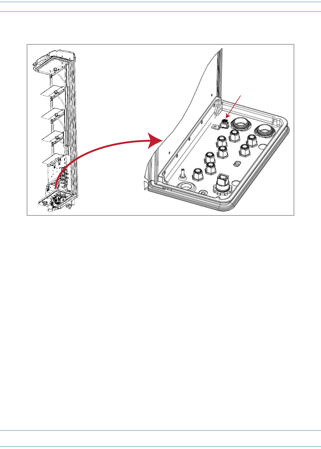
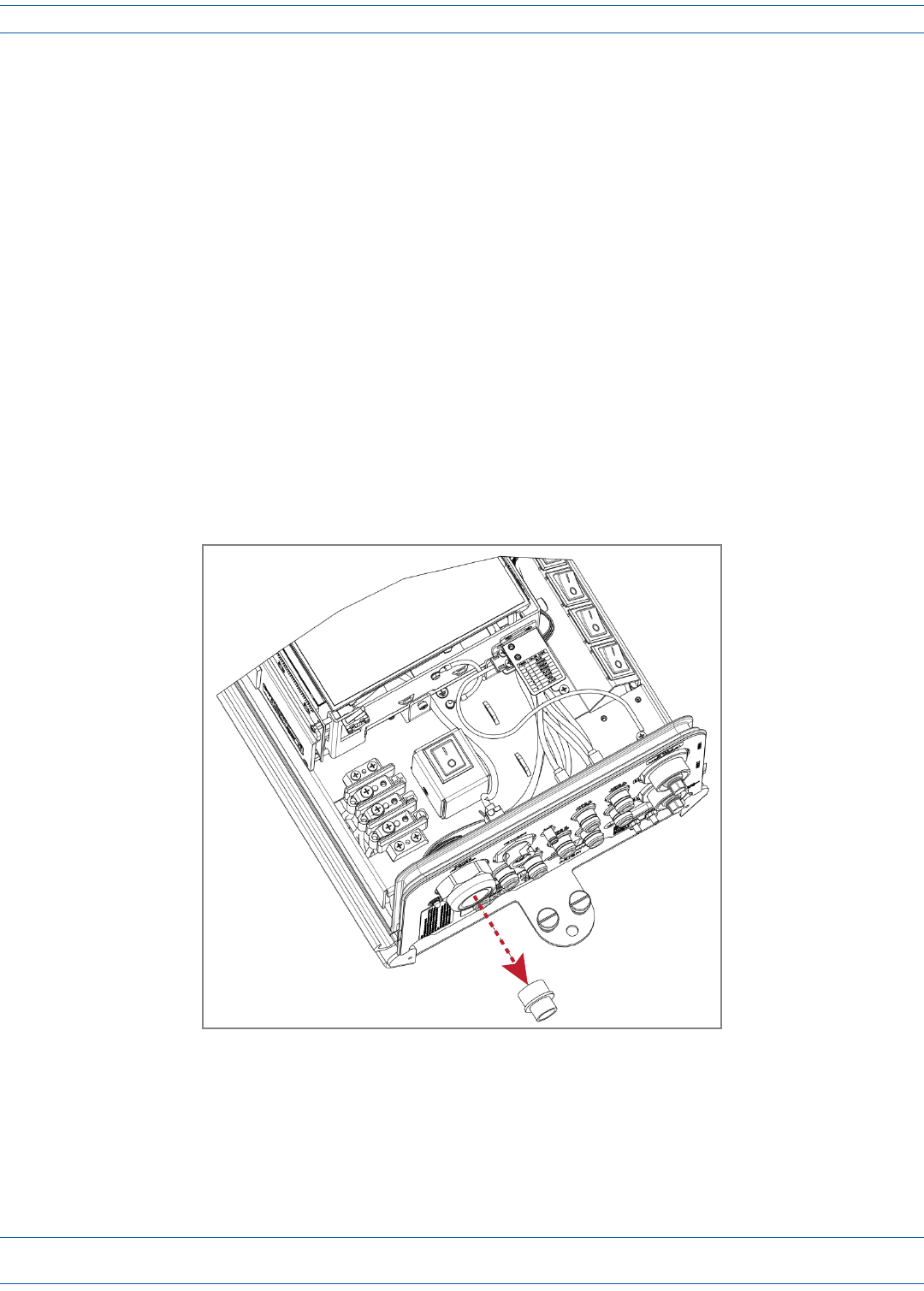
3Removethecable-glandplugfromthebottomofthePRUchassis:
Cable-gland plug
FlexWave® Prism Remote Unit and RF Module Installation Guide FWPP-504-02
Page 80 © May 2017 CommScope, Inc.
Install the Prism Remote Unit
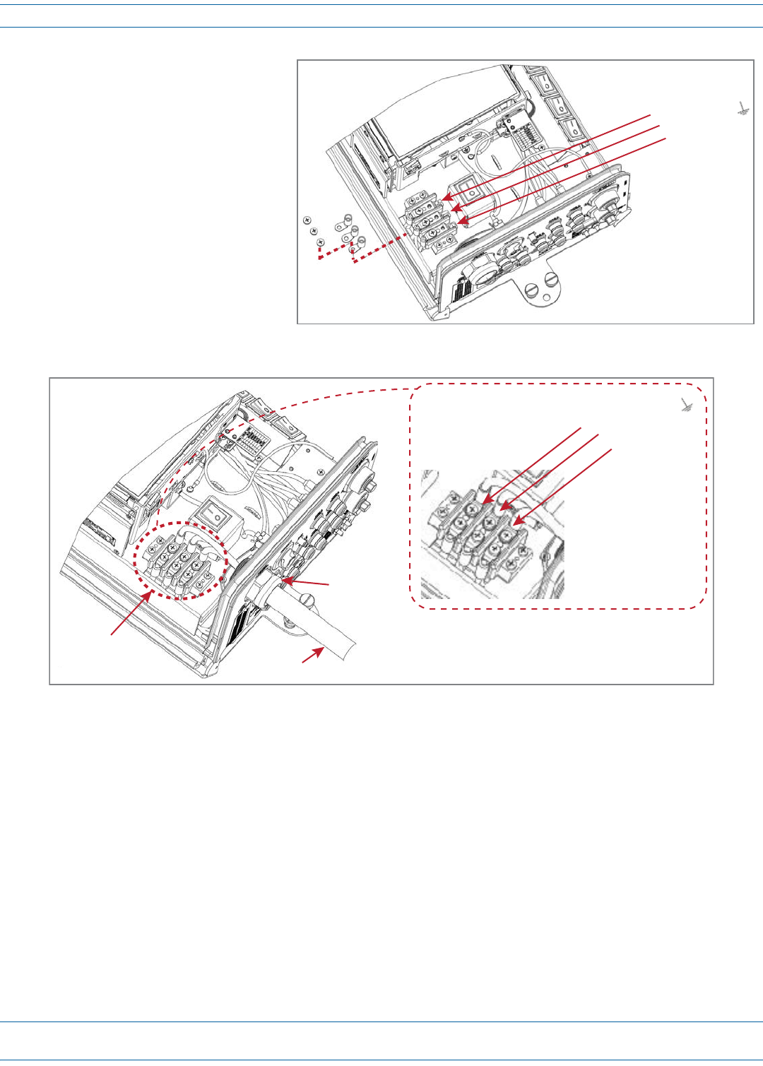
4Disconnecttheringterminalsfrom
thepower-terminalblock,as
showninthegraphictotheright.
5ConnecttheDCpowercabletothePRU.
aRoutetheendoftheDCpowercablewiththethreeconductorsthroughtheopencable-glandconnector
onthebottomofthePRU.
bCrimpthethreeconductorstothepowerringterminals.Theterminalblockislabeledastowhereeach
wireshouldbeconnected,asdescribedbelow.
•Inatypical-48Vdcplant,thehighestpotentialisthe0(groundorreturn)lead;youtherefore:
–connectthe0(groundorreturn)leadtothepositive(+)connector(redwire)
–connectthe-48Vdcleadtothenegative(-)connector(blackwire)
–connectthethirdwire,ifprovided,totheEarthGroundterminal.
•Ina+48Vdcplant,thehighestpotentialisthe+48lead;youtherefore:
–connectthe+48leadtothepositive(+)connector(redwire)
–connectthe0potential(groundorreturn)tothenegative(-)connector(blackwire)
–connectthethirdwire,ifprovided,totheEarthGroundterminal.
cUseaPhillipsscrewdrivertotorquetheringterminalsto18in-lbs.
dUsea42MMwrenchtotorquethelargenutoutsidethecableglandto44in-lbs.
Posive (+)
Negave (-)
Earth ground
Posive (+)
Negave (-)
Earth ground
Step 4a
Steps 4b and 4c
Step 4d

Install the Prism Remote Unit
FWPP-504-02 FlexWave® Prism Remote Unit and RF Module Installation Guide
© May 2017 CommScope, Inc. Page 81
6ConnectthewirestothedesignatedterminalsontheDCPowerSourceDistributionPanel.Thefollowing
connectionsaretypicallymade:
•Inatypical-48Vdcplant,thehighestpotentialisthe0(groundorreturn)lead;youtherefore:
–connectthe0(groundorreturn)leadtothepositive(+)connector(redwire)
–connectthe-48Vdcleadtothenegative(-)connector(blackwire)
–connectthethirdwire,ifprovided,totheEarthGroundterminal.
•Ina+48Vdcplant,thehighestpotentialisthe+48lead;youtherefore:
–connectthe+48leadtothepositive(+)connector(redwire)
–connectthe0potential(groundorreturn)tothenegative(-)connector(blackwire)
–connectthethirdwire,ifprovided,totheEarthGroundterminal.
7Dressandsecurethewirestotherackfollowinglocalpractice.Routewiringawayfromsharpedgesand
secureinplacetopreventchaffingandprovidestrainrelief.
NOTE: Route all DC input wiring away from any sharp edges and properly secure it in place to prevent chafing
and to provide strain relief. Lace the wires to the rack frame.
8Dooneofthefollowing:
•IfyouneedtoinstallanRFModule,goto"InstalltheRFModule(s)”onpage84.
•IftheRFModulesrequiredforthisinstallationarealreadyinstalledinthePRU,goto"PowerontheRF
Module(s)andthePrismRemoteUnit”onpage110.
FlexWave® Prism Remote Unit and RF Module Installation Guide FWPP-504-02
Page 82 © May 2017 CommScope, Inc.
Install the Prism Remote Unit
(OPTIONAL) CONNECT THE PRISM REMOTE UNIT TO A UPS
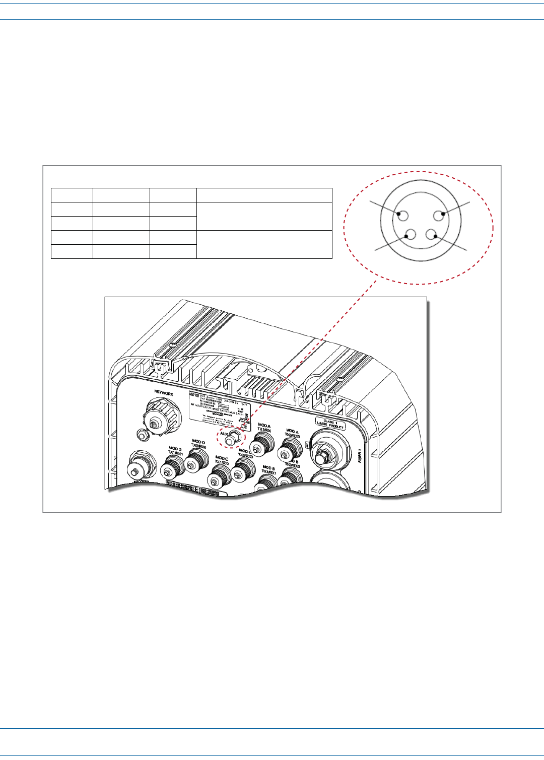
Thefour-pinAUXConnectoronthebottomofthePRUallowsthePRUtobeconnectedtoanexternaldevicewith
drycontactconnections,suchasanUninterruptedPowerSupply(UPS).TheAUXConnectorpinsareshownin
Figure17.
NOTE: The Normally Open (NO) or Normally Closed (NC) options are configurable in the GUI; see the “Manage
Contact Alarms” section of the current EMS System Setup and Provisioning Guide.
Figure 17. AUX Connector Pin Orientation
NOTE: The Major/Minor setting of the AUX Connector pins cannot be configured in the Prism 6.x EMS GUI. In
Prism 7.x, you can configure the Contact Alarm as Major or Minor (Alarms > Manage Contact Alarms).
1
2
4
3
AUX Connector
Boom of PRU
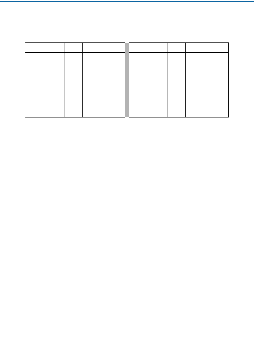
Pin # Contact Color Alarm Input
1 NO/NC Brown Major External Alarm Input
2 CO White
3 NO/NC Blue Minor External Alarm Input
4 CO Black
Install the Prism Remote Unit
FWPP-504-02 FlexWave® Prism Remote Unit and RF Module Installation Guide
© May 2017 CommScope, Inc. Page 83
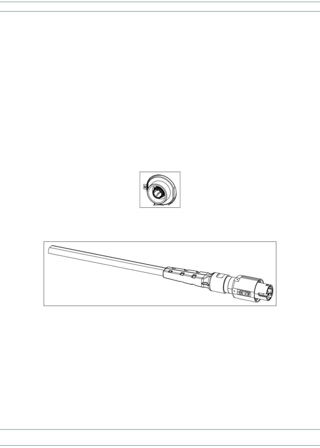
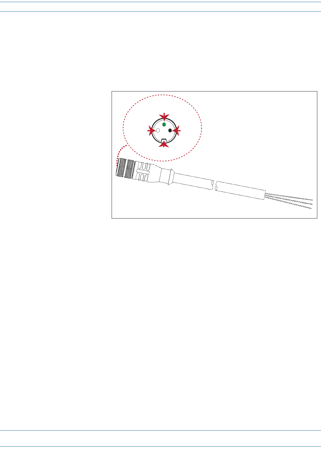
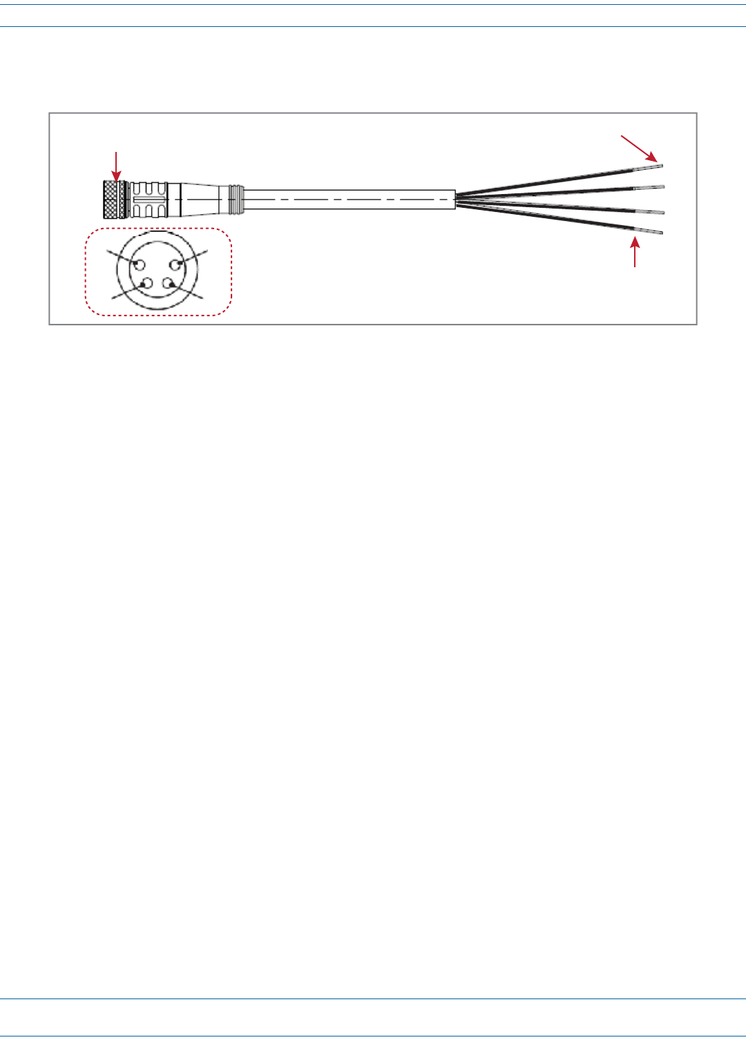
A4-WireM8picofast®6-or10-meter26AWGcableisusedtoconnectthePRUtotheexternaldevice,asshown
inFigure18.
Figure 18. 4-Wire picofast 26 AWG Cable
DothefollowingtoconnectaUPStotheAUXConnectoronthebottomofthePRU:
1Obtaintherequiredlengthof6-or10-meterpicofastcable.
2Orientthecouplingfasteneronthecable(Figure18)withtheAUXConnectorpins(Figure17),andthen
fastenthecabletotheAUXConnector.
3RoutethecablefromthePRUAUXConnectortotheUPS(ifnotalreadyrouted)andthencuttotherequired
length.Allowsufficientslackfordressingandorganizingthecableattheexternaldevice.
4Stripbacktheoutercablesheathandinsulationtoexposethewiresattheendofthecableandstripback0.2
inches(5mm)ofinsulationfromeachwire.
5Connectthealarmwirepairstotheappropriateterminalsontheexternaldevice.
6Dressandsecurecableperstandardindustrypractice.
NOTE: If necessary, order a Prism AUX 4-wire cable assembly, CommScope part number 1451903.
Strip cable
0.2 inches (5 mm)
Connect 4 wires to UPS
Connect to
PRU AUX Connector
24
13