ADC Telecommunications RPT080AA ADC's In-Building Wireless Repeater BDA - Cellular User Manual 75237p1
ADC Telecommunications Inc ADC's In-Building Wireless Repeater BDA - Cellular 75237p1
Contents
- 1. User manual 1
- 2. User manual 2
- 3. User manual 3
User manual 1
ADC In-Building
850 and 1900MHz Wireless Repeater
User Manual
1xxxxxx Rev A
ADCP-75-237 • Issue 1 • 8/2007

ADC In-Building
850 and 1900MHz Wireless Repeater
User Manual
ADCP-75-237 • Issue 1 • 8/2007
1xxxxxx Rev A

ADCP-75-237 • Issue 1 • 8/2007 • Preface
Page iv
COPYRIGHT
© 2007, ADC Telecommunications, Inc.
All Rights Reserved
REVISION HISTORY
ISSUE DATE REASON FOR CHANGE
1 08/2007 Original
LIST OF CHANGES
The technical changes incorporated into this issue are listed below.
PAGE IDENTIFIER DESCRIPTION OF CHANGE
All New publication
TRADEMARK INFORMATION
ADC and Digivance are registered trademarks of ADC Telecommunications, Inc.
DISCLAIMER OF LIABILITY
Contents herein are current as of the date of publication. ADC reserves the right to change the contents without prior notice. In no
event shall ADC be liable for any damages resulting from loss of data, loss of use, or loss of profits and ADC further
disclaims any and all liability for indirect, incidental, special, consequential or other similar damages. This disclaimer of
liability applies to all products, publications and services during and after the warranty period.
This publication may be verified at any time by contacting ADC’s Technical Assistance Center at 1-800-366-3891, extension 73476
(in U.S.A. or Canada) or 952-917-3476 (outside U.S.A. and Canada), or by e-mail to wireless.tac@adc.com
ADC Telecommunications, Inc.
P.O. Box 1101, Minneapolis, Minnesota 55440-1101
In U.S.A. and Canada: 1-800-366-3891
Outside U.S.A. and Canada: (952) 938-8080
Fax: (952) 917-1717

ADCP-75-237 • Issue 1 • 6/2007 • Preface
Page v
© 2007, ADC Telecommunications, Inc.
TABLE OF CONTENTS
Content Page
ABOUT THIS MANUAL . . . . . . . . . . . . . . . . . . . . . . . . . . . . . . . . . . . . . . . . . . . . . . . . . . . . . . . . . . . . . . . . . . . . . . . . vii
ADMONISHMENTS . . . . . . . . . . . . . . . . . . . . . . . . . . . . . . . . . . . . . . . . . . . . . . . . . . . . . . . . . . . . . . . . . . . . . . . . . . vii
GENERAL SAFETY PRECAUTIONS . . . . . . . . . . . . . . . . . . . . . . . . . . . . . . . . . . . . . . . . . . . . . . . . . . . . . . . . . . . . . . . . vii
FCC Compliance Statement . . . . . . . . . . . . . . . . . . . . . . . . . . . . . . . . . . . . . . . . . . . . . . . . . . . . . . . . . . . . . . . . . . . . viii
Class A viii
Class B viii
Certification: UL/ETL/CSA/CE/NEBS Listed (delete inapplicable items, here and in TOC) ix
Standards ix
STANDARDS CERTIFICATION . . . . . . . . . . . . . . . . . . . . . . . . . . . . . . . . . . . . . . . . . . . . . . . . . . . . . . . . . . . . . . . . . . . . ix
LIST OF ACRONYMS AND ABBREVIATIONS . . . . . . . . . . . . . . . . . . . . . . . . . . . . . . . . . . . . . . . . . . . . . . . . . . . . . . . . . . . x
SECTION 1:
OVERVIEW
1 DESCRIPTION . . . . . . . . . . . . . . . . . . . . . . . . . . . . . . . . . . . . . . . . . . . . . . . . . . . . . . . . . . . . . . . . . . . . . . . . .1-1
1.1 RF SIGNAL FLOW (850MHz) . . . . . . . . . . . . . . . . . . . . . . . . . . . . . . . . . . . . . . . . . . . . . . . . . . . . . . . . .1-1
1.2 RF SIGNAL FLOW (1900MHz) . . . . . . . . . . . . . . . . . . . . . . . . . . . . . . . . . . . . . . . . . . . . . . . . . . . . . . . .1-2
2 FEATURES . . . . . . . . . . . . . . . . . . . . . . . . . . . . . . . . . . . . . . . . . . . . . . . . . . . . . . . . . . . . . . . . . . . . . . . . . . .1-3
2.1 LED Status . . . . . . . . . . . . . . . . . . . . . . . . . . . . . . . . . . . . . . . . . . . . . . . . . . . . . . . . . . . . . . . . . . . . .1-3
2.2 Automatic Level Control (ALC). . . . . . . . . . . . . . . . . . . . . . . . . . . . . . . . . . . . . . . . . . . . . . . . . . . . . . . .1-3
2.3 Sleep Mode . . . . . . . . . . . . . . . . . . . . . . . . . . . . . . . . . . . . . . . . . . . . . . . . . . . . . . . . . . . . . . . . . . . .1-3
2.4 Isolation Check . . . . . . . . . . . . . . . . . . . . . . . . . . . . . . . . . . . . . . . . . . . . . . . . . . . . . . . . . . . . . . . . . .1-3
2.5 Over Power Shut Down . . . . . . . . . . . . . . . . . . . . . . . . . . . . . . . . . . . . . . . . . . . . . . . . . . . . . . . . . . . . .1-3
2.6 Graphical User Interface (GUI) . . . . . . . . . . . . . . . . . . . . . . . . . . . . . . . . . . . . . . . . . . . . . . . . . . . . . . .1-3
SECTION 2:
INSTALLATION
1 REPEATER INSTALLATION . . . . . . . . . . . . . . . . . . . . . . . . . . . . . . . . . . . . . . . . . . . . . . . . . . . . . . . . . . . . . . . .2-1
1.1 Mechanical Attachment of Repeater. . . . . . . . . . . . . . . . . . . . . . . . . . . . . . . . . . . . . . . . . . . . . . . . . . . .2-1
1.2 Installation of Repeater Cables . . . . . . . . . . . . . . . . . . . . . . . . . . . . . . . . . . . . . . . . . . . . . . . . . . . . . . .2-2
SECTION 3:
GRAPHICAL USER INTERFACE
1 INSTALL SOFTWARE. . . . . . . . . . . . . . . . . . . . . . . . . . . . . . . . . . . . . . . . . . . . . . . . . . . . . . . . . . . . . . . . . . . .3-1
2 OPERATING THE SOFTWARE. . . . . . . . . . . . . . . . . . . . . . . . . . . . . . . . . . . . . . . . . . . . . . . . . . . . . . . . . . . . . . .3-5
2.1 Menu Information . . . . . . . . . . . . . . . . . . . . . . . . . . . . . . . . . . . . . . . . . . . . . . . . . . . . . . . . . . . . . . . .3-5
2.2 Control Panel Information. . . . . . . . . . . . . . . . . . . . . . . . . . . . . . . . . . . . . . . . . . . . . . . . . . . . . . . . . . .3-6
2.3 Status Bar . . . . . . . . . . . . . . . . . . . . . . . . . . . . . . . . . . . . . . . . . . . . . . . . . . . . . . . . . . . . . . . . . . . . .3-8
3 SET COMMUNICATION PORT PROPERTIES . . . . . . . . . . . . . . . . . . . . . . . . . . . . . . . . . . . . . . . . . . . . . . . . . . . . .3-8
4 US_PCS TEST SCREEN . . . . . . . . . . . . . . . . . . . . . . . . . . . . . . . . . . . . . . . . . . . . . . . . . . . . . . . . . . . . . . . . . . 3-10

ADCP-75-237 • Issue 1 • 6/2007 • Preface
Page vi
© 2007, ADC Telecommunications, Inc.
TABLE OF CONTENTS
Content Page
4.1 Fwd Base Volt. . . . . . . . . . . . . . . . . . . . . . . . . . . . . . . . . . . . . . . . . . . . . . . . . . . . . . . . . . . . . . . . . . 3-10
4.2 Rev Base Volt . . . . . . . . . . . . . . . . . . . . . . . . . . . . . . . . . . . . . . . . . . . . . . . . . . . . . . . . . . . . . . . . . . 3-11
4.3 Band Selection . . . . . . . . . . . . . . . . . . . . . . . . . . . . . . . . . . . . . . . . . . . . . . . . . . . . . . . . . . . . . . . . 3-11
4.4 Attenuation Test: MGC / ALC Control . . . . . . . . . . . . . . . . . . . . . . . . . . . . . . . . . . . . . . . . . . . . . . . . . . 3-11
4.5 Gain Offset Box. . . . . . . . . . . . . . . . . . . . . . . . . . . . . . . . . . . . . . . . . . . . . . . . . . . . . . . . . . . . . . . . . 3-11
4.6 Fwd PLL Attenuation Control. . . . . . . . . . . . . . . . . . . . . . . . . . . . . . . . . . . . . . . . . . . . . . . . . . . . . . . . 3-11
4.7 Rev Pll Attenuation Control . . . . . . . . . . . . . . . . . . . . . . . . . . . . . . . . . . . . . . . . . . . . . . . . . . . . . . . . 3-11
SECTION 4:
GENERAL INFORMATION
1 WARRANTY/SOFTWARE . . . . . . . . . . . . . . . . . . . . . . . . . . . . . . . . . . . . . . . . . . . . . . . . . . . . . . . . . . . . . . . . . 4-1
2 SOFTWARE SERVICE AGREEMENT . . . . . . . . . . . . . . . . . . . . . . . . . . . . . . . . . . . . . . . . . . . . . . . . . . . . . . . . . . 4-1
3 REPAIR/EXCHANGE POLICY . . . . . . . . . . . . . . . . . . . . . . . . . . . . . . . . . . . . . . . . . . . . . . . . . . . . . . . . . . . . . . . 4-1
4 REPAIR CHARGES. . . . . . . . . . . . . . . . . . . . . . . . . . . . . . . . . . . . . . . . . . . . . . . . . . . . . . . . . . . . . . . . . . . . . . 4-2
5 REPLACEMENT/SPARE PRODUCTS . . . . . . . . . . . . . . . . . . . . . . . . . . . . . . . . . . . . . . . . . . . . . . . . . . . . . . . . . . 4-2
6 RETURNED MATERIAL. . . . . . . . . . . . . . . . . . . . . . . . . . . . . . . . . . . . . . . . . . . . . . . . . . . . . . . . . . . . . . . . . . . 4-2

ADCP-75-237 • Issue 1 • 8/2007 • Preface
Page vii
© 2007, ADC Telecommunications, Inc.
ABOUT THIS MANUAL
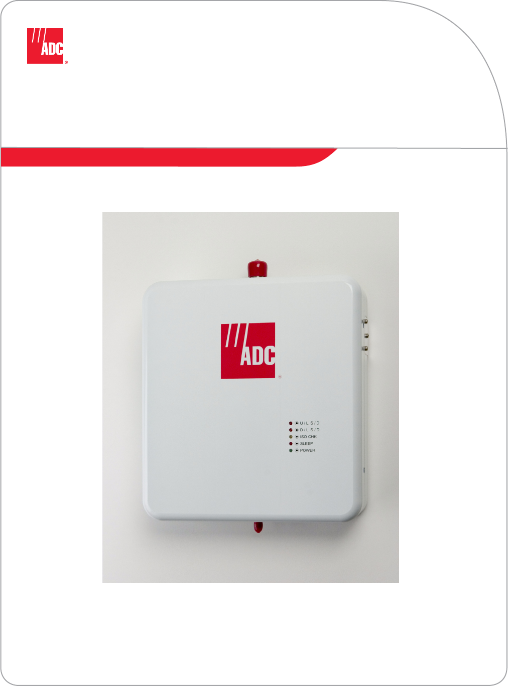
This manual describes the installation and operation of the ADC In-Building Wireless Repeater.
The repeater is normally mounting inside and distributes the RF over coax to an indoor antenna
located in the desired coverage area.
ADMONISHMENTS
Important safety admonishments are used throughout this manual to warn of possible hazards to
persons or equipment. An admonishment identifies a possible hazard and then explains what
may happen if the hazard is not avoided. The admonishments — in the form of Dangers,
Warnings, and Cautions — must be followed at all times.
These warnings are flagged by use of the triangular alert icon (seen below), and are listed in
descending order of severity of injury or damage and likelihood of occurrence.
Danger: Danger is used to indicate the presence of a hazard that will cause severe personal
injury, death, or substantial property damage if the hazard is not avoided.
Warning: Warning is used to indicate the presence of a hazard that can cause severe personal
injury, death, or substantial property damage if the hazard is not avoided.
Caution: Caution is used to indicate the presence of a hazard that will or can cause minor
personal injury or property damage if the hazard is not avoided.
GENERAL SAFETY PRECAUTIONS
List here all general admonishments which apply throughout procedures within the manual.
-
Warning: Wet conditions increase the potential for receiving an electrical shock when
installing or using electrically-powered equipment. To prevent electrical shock, never install or
use electrical equipment in a wet location or during a lightning storm.
Danger: This equipment uses a Class 1 Laser according to FDA/CDRH rules. Laser radiation
can seriously damage the retina of the eye. Do not look into the ends of any optical fiber. Do not
look directly into the optical transceiver of any digital unit or exposure to laser radiation may
result. An optical power meter should be used to verify active fibers. A protective cap or hood
MUST be immediately placed over any radiating transceiver or optical fiber connector to avoid
the potential of dangerous amounts of radiation exposure. This practice also prevents dirt
particles from entering the adapter or connector.
Caution: This system is a RF Transmitter and continuously emits RF energy. Maintain 3 foot
(91.4 cm) minimum clearance from the antenna while the system is operating. Wherever
possible, shut down the RAN before servicing the antenna.

Caution: Always allow sufficient fiber length to permit routing of patch cords and pigtails
without severe bends. Fiber optic patch cords or pigtails may be permanently damaged if bent
or curved to a radius of less than 2 inches (5.1 cm).
Caution: Exterior surfaces of the RAN may be hot. Use caution during servicing.
ADCP-75-237 • Issue 1 • 8/2007 • Preface
Page viii
© 2007, ADC Telecommunications, Inc.
FCC Compliance Statement
The writer may pick from Class A or Class B (below) if either is applicable, or may omit this
statement entirely if not needed. The heading for Class A or Class B may also be deleted. Fill
the product name in to replace the X at the beginning of the text.
Class A
X has been certified to comply with the requirements for class A computing devices per part 15
of the FCC regulations.
Warning: This equipment generates, uses, and can radiate radio frequency energy and if not
installed and used in accordance with the instruction manual, may cause interference to radio
communications. It has been tested and found to comply with limits for a Class A digital device
pursuant to Subpart B of Part 15 of FCC Rules, which are designed to provide reasonable
protection against such interference when operated in a commercial environment. Operation of
this equipment in a residential area is likely to cause interference to TV and radio reception in
which case the user, at their own expense, will be required to take whatever measures may be
required to correct the interference.
This equipment does not exceed Class A limits for radio emission for digital apparatus, set out
in the radio interference regulation of the authorization methods of Industry Canada. Operation
in a residential area may cause unacceptable interference to TV and radio reception requiring
the owner or operator to take whatever steps are necessary to correct the interference.
This product conforms to all applicable standards of 21 CFR 1040.
Class B
X complies with Part 15 of the FCC Rules. Operation is subject to the following two conditions;
(1) this device may not cause harmful interference, and (2) this device must accept any
interference received, including interference that may cause undesired operation.

Warning: This equipment generates, uses, and can radiate radio frequency energy and if not
installed and used in accordance with the instruction manual, may cause interference to radio
communications. It has been tested and found to comply with limits for a Class B digital device
pursuant to Subpart A of Part 15 of FCC Rules, which are designed to provide reasonable
protection against such interference when operated in a residential environment. If interference
to TV and radio reception does occur relocate or reorient the antenna of the affected radio or TV.
This equipment does not exceed Class B limits for radio emission for digital apparatus, set out
in the radio interference regulation of the authorization methods of Industry Canada.
This product conforms to all applicable standards of 21 CFR 1040.
ADCP-75-237 • Issue 1 • 8/2007 • Preface
Page ix
© 2007, ADC Telecommunications, Inc.
Certification: UL/ETL/CSA/CE/NEBS Listed (delete inapplicable items, here and in TOC)
State condition of UL, ETL and/or CSA status. An example: X has been tested and found to
comply with the requirements of UL/CSA 60950.
XXX modules and chassis have been tested and found to comply with all applicable CE
Directives.
XXXX complies with the requirements of GR-63-CORE, Issue 1, October 1995 and GR-1089-
CORE, Issue 2, December 1997 with Revision 1, February 1999 as specified in SR-3580, Issue
1, 1995.
Standards
The following listing is a bibliography of applicable ANSI and Bellcore documents:
ANSI T1.403-1989 Carrier-to-Customer Installation — DS1 Metallic Interface, February 22,
1989.
ANSI T1E1.4/91-002R2 Study of the Feasibility and Advisability of Digital Subscriber Lines
Operating at Rates Substantially in Excess of the Basic Rate.
etc.
etc.
STANDARDS CERTIFICATION
Below is an alternative format for standards certification.
FCC: The Digivance NXD complies with the applicable sections of Title 47 CFR Part 15, 22,
24 and 90.
The Digivance NXD Hub has been tested and found to comply with the limits for a Class A dig-
ital device, pursuant to Part 15 of the FCC rules. These limits are designed to provide reasonable
protection against harmful interference when the equipment is operated in a commercial envi-
ronment. This equipment generates, uses, and can radiate radio frequency energy and, if not
installed and used in accordance with the instruction manual, may cause harmful interference to

ADCP-75-237 • Issue 1 • 8/2007 • Preface
Page x
© 2007, ADC Telecommunications, Inc.
radio communications.
Changes and modifications not expressly approved by the manufacturer or registrant of this
equipment can void your authority to operate this equipment under Federal Communications
Commissions rules.
In order to maintain compliance with FCC regulations, shielded cables must be used with this
equipment. Operation with non-approved equipment or unshielded cables is likely to result in
interference to radio & television reception.
ETL: This equipment complies with ANSI/UL 60950-1 Information Technology Equipment.
This equipment provides the degree of protection specified by IP24 as defined in IEC
Publication 529. Ethernet signals are not for outside plant use.
FDA/CDRH: This equipment uses a Class 1 LASER according to FDA/CDRH Rules. This
product conforms to all applicable standards of 21 CFR Part 1040.
IC: This equipment complies with the applicable sections of RSS-131. The term “IC:” before
the radio certification number only signifies that Industry Canada Technical Specifications
were met.
Wind Loading: The NXD RAN is able to withstand wind loads up to 150 mph.
LIST OF ACRONYMS AND ABBREVIATIONS
Below is an example of a list of this type.
The acronyms and abbreviations used in this manual are detailed in the following list:
AC Alternating Current
ANT Multiband Antenna
BIM Base Station Interface Module
BTS Base Transceiver Station
CCentigrade
CDRH Center for Devices and Radiological Health
C/MCPLR Cellular SMR Multicoupler
CM Centimeter
cPCI CompactPCI
CPU Central Processing Unit
CXD Compact RAN
DAS Distributed Antenna System
dB(FS) decibals (Full Scale – digital reading)
DC Direct Current
Div Diversity
EMS Element Management System
ESD Electrostatic Discharge
FFahrenheit

ADCP-75-237 • Issue 1 • 8/2007 • Preface
Page xi
© 2007, ADC Telecommunications, Inc.
FDA U.S. Food and Drug Administration
FCC U.S. Federal Communications Commission
GPS Global Positioning System
IC Industry Canada
IN Inch
IP Internet Protocol
KG Kilogram
LED Light Emitting Diode
LSE Location Services Equipment
LVD Low Voltage Disconnect
MHz Mega Hertz
MTBF Mean Time Between Failure
MUX Multiplexer
Node Any CPU in the Digivance NXD system
NXD Digivance Neutral Host Product Line
OSP Outside Plant
PA Power Amplifier
PAA Power Amplifier Assembly
PC Personal Computer
PCI Peripheral Component Interconnect bus
PIC PA Interface Controller
P/MCPLR PCS Multicoupler
RAN Radio Access Node
RDC RAN Down Converter
RDC2 RAN Down Converter Version 2
RF Radio Frequency
RUC RAN Up Converter
RUC2.X RAN Up Converter Version 2.X
RUC3 RAN Up Converter Version 3
SFP Small Form-Factor Pluggable Optical Transceiver
SIF Sonet Interface Module
SNMP Simple Network Management Protocol
SONET Synchronous Optical Network
STF2 System Interface Module
UL Underwriters Laboratories
VAC Volts Alternating Current
VDC Volts Direct Current
VSWR Voltage Standing Wave Ratio
WDM Wave Division Multiplex
WSP Wireless Service Provider

ADCP-75-237 • Issue 1 • 8/2007 • Preface
Page xii
© 2007, ADC Telecommunications, Inc.

ADCP-75-237 • Issue 1 • 8/2007 • Section 1: OVERVIEW
Page 1-1
© 2007, ADC Telecommunications, Inc.
SECTION 1: OVERVIEW
Content Page
1 DESCRIPTION . . . . . . . . . . . . . . . . . . . . . . . . . . . . . . . . . . . . . . . . . . . . . . . . . . . . . . . . . . . . . . . . . . . . . . . . .1-1
1.1 RF SIGNAL FLOW (850MHz) . . . . . . . . . . . . . . . . . . . . . . . . . . . . . . . . . . . . . . . . . . . . . . . . . . . . . . . . .1-1
1.1.1 Forward (Down) Link . . . . . . . . . . . . . . . . . . . . . . . . . . . . . . . . . . . . . . . . . . . . . . . . . . . . . . 1-1
1.1.2 Reverse(Up) Link . . . . . . . . . . . . . . . . . . . . . . . . . . . . . . . . . . . . . . . . . . . . . . . . . . . . . . . . 1-2
1.2 RF SIGNAL FLOW (1900MHz) . . . . . . . . . . . . . . . . . . . . . . . . . . . . . . . . . . . . . . . . . . . . . . . . . . . . . . . .1-2
1.2.1 Forward(Down) Link . . . . . . . . . . . . . . . . . . . . . . . . . . . . . . . . . . . . . . . . . . . . . . . . . . . . . . 1-2
1.2.2 Reverse(Up) Link . . . . . . . . . . . . . . . . . . . . . . . . . . . . . . . . . . . . . . . . . . . . . . . . . . . . . . . . 1-2
2 FEATURES . . . . . . . . . . . . . . . . . . . . . . . . . . . . . . . . . . . . . . . . . . . . . . . . . . . . . . . . . . . . . . . . . . . . . . . . . . .1-3
2.1 LED Status . . . . . . . . . . . . . . . . . . . . . . . . . . . . . . . . . . . . . . . . . . . . . . . . . . . . . . . . . . . . . . . . . . . . .1-3
2.2 Automatic Level Control (ALC). . . . . . . . . . . . . . . . . . . . . . . . . . . . . . . . . . . . . . . . . . . . . . . . . . . . . . . .1-3
2.3 Sleep Mode . . . . . . . . . . . . . . . . . . . . . . . . . . . . . . . . . . . . . . . . . . . . . . . . . . . . . . . . . . . . . . . . . . . .1-3
2.4 Isolation Check . . . . . . . . . . . . . . . . . . . . . . . . . . . . . . . . . . . . . . . . . . . . . . . . . . . . . . . . . . . . . . . . . .1-3
2.5 Over Power Shut Down . . . . . . . . . . . . . . . . . . . . . . . . . . . . . . . . . . . . . . . . . . . . . . . . . . . . . . . . . . . . .1-3
2.6 Graphical User Interface (GUI) . . . . . . . . . . . . . . . . . . . . . . . . . . . . . . . . . . . . . . . . . . . . . . . . . . . . . . .1-3
2.6.1 850MHZ Repeater Band Selection . . . . . . . . . . . . . . . . . . . . . . . . . . . . . . . . . . . . . . . . . . . . . 1-4
2.6.2 1900MHZ Repeater Band Selection . . . . . . . . . . . . . . . . . . . . . . . . . . . . . . . . . . . . . . . . . . . . 1-4
_________________________________________________________________________________________________________
1 DESCRIPTION
The repeater transmits RF in both directions to provide indoor wireless coverage. The device is
connected via coax to a donor antenna that is typically located on a rooftop or external wall of a
building, directed at the donor cell-site. The repeater is mounted inside the building and
distributes the RF over coax to an indoor antenna located in the desired coverage area.
1.1 RF SIGNAL FLOW (850MHz)
1.1.1 Forward (Down) Link
The base station signal raging from 869 ~ 894MHz is received by the Donor antenna. Then
going through the duplexer removing the unwanted signals received by the LNA. The forward
link signal received by the LNA goes through a BPF (Band Pass Filter) then is amplified by the
drive amplifier. The signal then goes through the LAN, and a Down Mixer where IF signal
conversion is done. This IF signal then goes through an IF SAW Filter adding two banda of
11+1.5MHz and 10+2.5MHz, totaling 25MHz, after filtering the signal. This signal now moves
to an up mixer to be converted to RF frequency and sent to a final stage amplifier. The final
stage amplifier’s output power goes through duplexer. The signal then goes through the service
antenna transmitting the forward link signal to the handsets.

ADCP-75-237 • Issue 1 • 8/2007 • Section 1: OVERVIEW
Page 1-2
© 2007, ADC Telecommunications, Inc.
1.1.2 Reverse(Up) Link
The reverse link and the forward link have a same structure. Frequency raging from 824 ~
849MHz received by the service antenna go into the duplexer. The duplexer removes all unwanted
signals and sends the specific signal to the LNA. The reverse link signal received by the LAN is
amplified by the drive amplifier and Down Mixer where IF signal conversion is done.
The IF signal then goes through IF SAW Filter adding two bands of 11+1.5MHz and
10+2.5MHz, totaling 25MHz, after filtering the signal. This signal now moves to up mixer to be
converted to the RF frequency and sent to a final stage amplifier. The signal in final stage
amplifier undergoes through duplexer. Then the signal goes through the donor antenna,
transmitting reverse link signal to base stations.
1.2 RF SIGNAL FLOW (1900MHz)
1.2.1 Forward(Down) Link
The base station signal ranging from 1930 ~ 1990MHz is received by the Donor antenna. It
passes through the duplexer removing the unwanted reverse path signals received by the LNA.
The forward link signal received by the LNA goes through a BPF (Band Pass Filter) then is
amplified by the drive amplifier. The signal than goes through the LNA and a Down Mixer
where IF signal conversion is done. This IF signal then goes through an IF SAW Filter adding
two bands of 15MHz and 5MHz, totaling 20MHz, after filtering the signal. This signal now
moves to an up mixer to be converted to the RF frequency and sent to a final stage amplifier.
The final stage amplifier's output power goes through the duplexer. The signal then goes
through the service antenna transmitting the forward link signal to the handsets.
1.2.2 Reverse(Up) Link
The reverse link and the forward link have the same structure. Frequencies raging from 1850 ~
1910MHz received by the service antenna go into the duplexer. The duplexer removes all
unwanted signals and sends the specific signal to the LNA. The reverse link signal received by the
LAN is amplified by the drive amplifier and Down Mixer where IF signal conversion is done.
The IF signal then goes through IF SAW Filter adding two bands of 15MHz and 5MHz, totaling
20MHz, after filtering the signal. This signal now moves to up mixer to be converted to the RF
frequency and sent to a final stage amplifier. The signal in final stage amplifier undergoes
through duplexer. Then the signal goes through the donor antenna, transmitting reverse link
signal to base stations.

ADCP-75-237 • Issue 1 • 8/2007 • Section 1: OVERVIEW
Page 1-3
© 2007, ADC Telecommunications, Inc.
2 FEATURES
2.1 LED Status
Five LEDs on the front display repeaters status. LED indicators are defined in Table 1-1.
Table 1-1.LED Indicators
COLOR STATUS
Red Tx Shut Down
Red Rx Shut Down
Yellow Sleep Mode
Red Isolation Check
Green DC Power
2.2 Automatic Level Control (ALC)
If the forward or reverse RF output power exceeds 13dBm, the system automatically controls
the output power to maintain power and protect the repeater.
2.3 Sleep Mode
Sleep Mode is activated when the reverse output RF power drops below –65dBm for more than
three minutes. The repeater returns to normal operation when the signal goes over –65dBm.
2.4 Isolation Check
Isolation check LED for the forward path and reverse path comes on after the Donor antenna is
set up and the power is turned on. Automatic Gain set up is available within the repeater for the
Path - Isolation.
2.5 Over Power Shut Down
If the RF output power exceeds the maximum for more than five seconds, the repeater
automatically shuts down. After five minutes, the repeater checks and monitors the RF Power, if
the RF output power is above the maximum, repeater remains shut down. If RF output power is
back to normal, the repeater comes back on.
2.6 Graphical User Interface (GUI)
The GUI control interface is used to change to Sleep Mode, select different bands A, B, C, D, E,
and F of the US PCS service. Other features of the BDU such as the On/Off controls of the
system can be accessed through the USB port provided. All control is set “Automatic” when
shipped, you can change the setting using the GUI control interface provided.
ADCP-75-237 • Issue 1 • 8/2007 • Section 1: OVERVIEW
Page 1-4
© 2007, ADC Telecommunications, Inc.
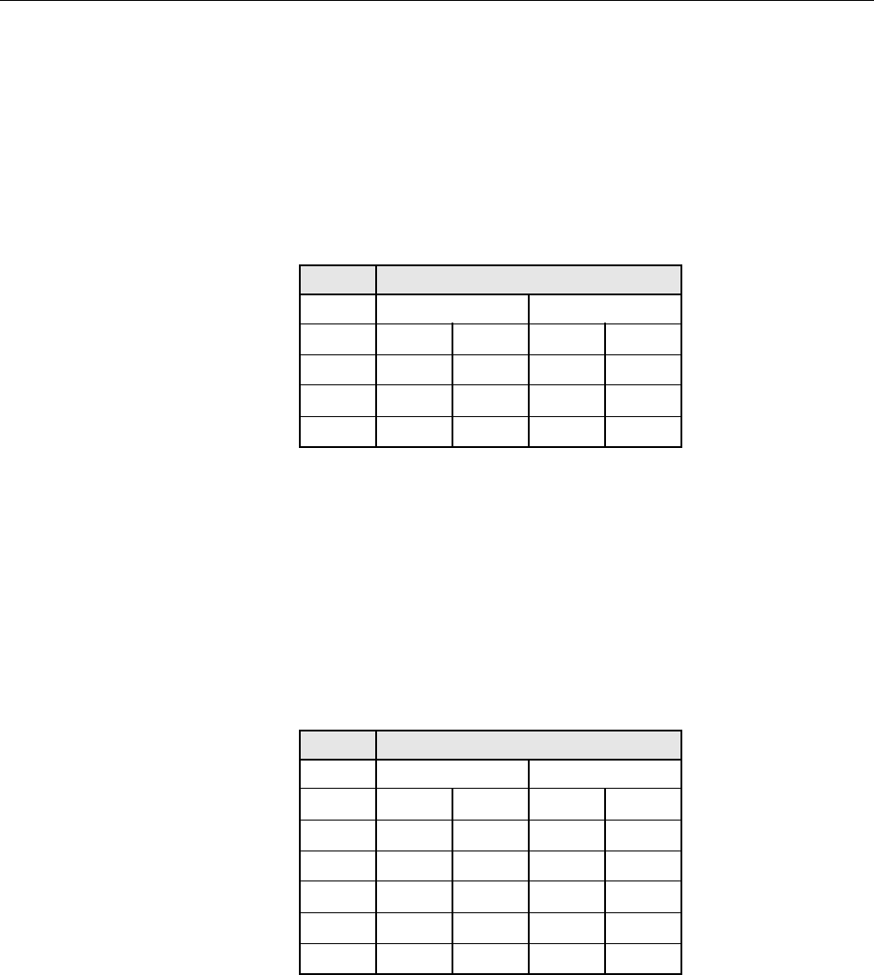
2.6.1 850MHZ Repeater Band Selection
Band Selection is available within the US CELLULAR 25MHz bandwidth. User can select
either A band set (A”+A +A’) or B band set (B + B’) for 12.5MHz Bandwidth each, totaling
25MHz, or request the manufacturer to set the bandwidth before shipping the product from the
factory. Band selection is shown in Table 1-2.
Table 1-2.Band Selection Table (850MHz)
FREQUENCY (MHZ)
BAND DOWNLINK UPLINK
A”+A 869 880 824 835
B 880 890 835 845
A’ 890 891.5 845 846.5
B’ 891.5 894 846.5 849
2.6.2 1900MHZ Repeater Band Selection
Band selection is available within the US PCS 60MHz bandwidth. You can select any A, B, or C
band(15MHz each, group1) and any D, E, or F band (5MHz each, group1) for a total 20MHz
Bandwidth each, or request the manufacturer to set bandwidth before shipping product from the
factory. Example; select A + E, or C + D, or A + F or any combination, but not two bands within
the same group. You can also choose to use only one band among the six bands available. Band
selection is shown in Table 1-3.
Table 1-3.Band Selection Table (1900MHz)
FREQUENCY (MHZ)
BAND DOWNLINK UPLINK
A 1930 1945 1850 1865
D 1940 1950 1865 1870
B 1950 1965 1870 1885
E 1965 1970 1885 1890
F 1970 1975 1890 1895
C 1975 1990 1895 1910

ADCP-75-237 • Issue 1 • 8/2007 • Section 2: Installation
Page 2-1
© 2007, ADC Telecommunications, Inc.
SECTION 2: INSTALLATION
Content Page
1 REPEATER INSTALLATION . . . . . . . . . . . . . . . . . . . . . . . . . . . . . . . . . . . . . . . . . . . . . . . . . . . . . . . . . . . . . . . .2-1
1.1 Mechanical Attachment of Repeater. . . . . . . . . . . . . . . . . . . . . . . . . . . . . . . . . . . . . . . . . . . . . . . . . . . .2-1
1.1.1 Standard Wall Mount . . . . . . . . . . . . . . . . . . . . . . . . . . . . . . . . . . . . . . . . . . . . . . . . . . . . . . 2-1
1.1.2 Masonry Wall Mount . . . . . . . . . . . . . . . . . . . . . . . . . . . . . . . . . . . . . . . . . . . . . . . . . . . . . . 2-1
1.2 Installation of Repeater Cables . . . . . . . . . . . . . . . . . . . . . . . . . . . . . . . . . . . . . . . . . . . . . . . . . . . . . . .2-2
_________________________________________________________________________________________________________
1 REPEATER INSTALLATION
The repeater should be mounted in accordance with local code using appropriate hardware
(customer provided). Repeater must be installed within six feet of an AC power source (100–240
VAC 50 or 60 Hz). The repeater mounting bracket has four mounting holes, as shown in
Figure 2-1
. Below are guidelines for standard wall mount and masonry wall mount of the
repeater.
Figure 2-1. Wall Mount Bracket
1.1 Mechanical Attachment of Repeater
Warning: Never install the repeater in a wet location or during a lightning storm. When
installing or modifying communication lines, disconnect lines at the interface before working
with uninsulated lines or terminals to prevent electrical shock.
1.1.1 Standard Wall Mount
When mounting the repeater on a wooden or metal surface, it is recommended that it be installed
on pressure-treated plywood (customer provided) with a minimum thickness of 0.75–inch (19.0
cm). The plywood should be firmly secured to the wall studs.
1.1.2 Masonry Wall Mount
When mounting the
repeater
on a masonry surface, it is important that the bolts (especially the
upper bolts) be located as close as possible to the center of bricks or blocks.

ADCP-75-237 • Issue 1 • 8/2007 • Section 2: Installation
Page 2-2
© 2007, ADC Telecommunications, Inc.
Figure 2. Example of PDU Standard Wall Mount
1.2 Installation of Repeater Cables
There are four connection points on the repeater; two antenna connectors, one power connector,
and one USB port.
A USB cable is required when configuring the repeater using the GUI. Plug one end of the USB
cable into the port on the bottom of the repeater and plug the other end into a USB port
connected to the PC.
Power Connection
Donor Antenna
Indoor Antenna
1. Connect the ground cable under the grounding screw on the PDU front panel. Connect the
other end of the cable to the site grounding pole.

ADCP-75-237 • Issue 1 • 8/2007 • Section 2: Installation
Page 2-3
© 2007, ADC Telecommunications, Inc.
2. Connect the alarm cable leads to the base station or site alarm system. Use either
“Normally Open” or “Normally Closed” contacts. shows the PDU alarm logic
3. Connect the other end of the alarm cable to the PDU “ALARM” connector.
4. Connect the power cable to the site DC power connector. (The power cable has three leads.
Red is positive, Black is negative, and Yellow/Green is for ground.)
5. Connect the power cable to the “INPUT” connector on the PDU front panel.
6. When connecting a Remote Electrical Tilt (RET) system, connect an RS-485 cable from
the RET controller to the RS-485 connector on the PDU. PDU RS-485 connector
information is shown in . The recommended plug is a Molex® Mini-Fit® 71694-1103 or
equivalent.

ADCP-75-237 • Issue 1 • 8/2007 • Section 2: Installation
Page 2-4
© 2007, ADC Telecommunications, Inc.
ADCP-75-237 • Issue 1 • 8/2007 • Section 3: Graphical User Interface
Page 3-1
© 2007, ADC Telecommunications, Inc.
SECTION 3: GRAPHICAL USER INTERFACE
Content Page
1 INSTALL SOFTWARE. . . . . . . . . . . . . . . . . . . . . . . . . . . . . . . . . . . . . . . . . . . . . . . . . . . . . . . . . . . . . . . . . . . .3-1
2 OPERATING THE SOFTWARE. . . . . . . . . . . . . . . . . . . . . . . . . . . . . . . . . . . . . . . . . . . . . . . . . . . . . . . . . . . . . . .3-5
2.1 Menu Information . . . . . . . . . . . . . . . . . . . . . . . . . . . . . . . . . . . . . . . . . . . . . . . . . . . . . . . . . . . . . . . .3-5
2.2 Control Panel Information. . . . . . . . . . . . . . . . . . . . . . . . . . . . . . . . . . . . . . . . . . . . . . . . . . . . . . . . . . .3-6
2.3 Status Bar . . . . . . . . . . . . . . . . . . . . . . . . . . . . . . . . . . . . . . . . . . . . . . . . . . . . . . . . . . . . . . . . . . . . .3-8
3 SET COMMUNICATION PORT PROPERTIES . . . . . . . . . . . . . . . . . . . . . . . . . . . . . . . . . . . . . . . . . . . . . . . . . . . . .3-8
4 US_PCS TEST SCREEN . . . . . . . . . . . . . . . . . . . . . . . . . . . . . . . . . . . . . . . . . . . . . . . . . . . . . . . . . . . . . . . . . . 3-10
4.1 Fwd Base Volt . . . . . . . . . . . . . . . . . . . . . . . . . . . . . . . . . . . . . . . . . . . . . . . . . . . . . . . . . . . . . . . . . . 3-10
4.2 Rev Base Volt . . . . . . . . . . . . . . . . . . . . . . . . . . . . . . . . . . . . . . . . . . . . . . . . . . . . . . . . . . . . . . . . . . 3-11
4.3 Band Selection . . . . . . . . . . . . . . . . . . . . . . . . . . . . . . . . . . . . . . . . . . . . . . . . . . . . . . . . . . . . . . . . . 3-11
4.4 Attenuation Test: MGC / ALC Control. . . . . . . . . . . . . . . . . . . . . . . . . . . . . . . . . . . . . . . . . . . . . . . . . . . 3-11
4.5 Gain Offset Box . . . . . . . . . . . . . . . . . . . . . . . . . . . . . . . . . . . . . . . . . . . . . . . . . . . . . . . . . . . . . . . . . 3-11
4.6 Fwd PLL Attenuation Control . . . . . . . . . . . . . . . . . . . . . . . . . . . . . . . . . . . . . . . . . . . . . . . . . . . . . . . . 3-11
4.7 Rev Pll Attenuation Control . . . . . . . . . . . . . . . . . . . . . . . . . . . . . . . . . . . . . . . . . . . . . . . . . . . . . . . . . 3-11
_________________________________________________________________________________________________________
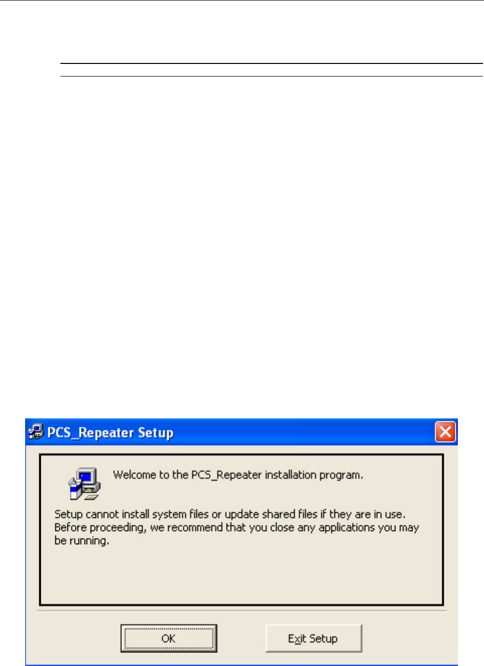
1 INSTALL SOFTWARE
Software comes in a zip file and must be un-zipped before it can be installed on the PC. Un-zip
“pcs_setup.zip” file to a temporary directory. Double click “setup.exe” file to start installation.
When PCS_Repeater Setup screen appears, click “OK”
ADCP-75-237 • Issue 1 • 8/2007 • Section 3: Graphical User Interface
Page 3-2
© 2007, ADC Telecommunications, Inc.
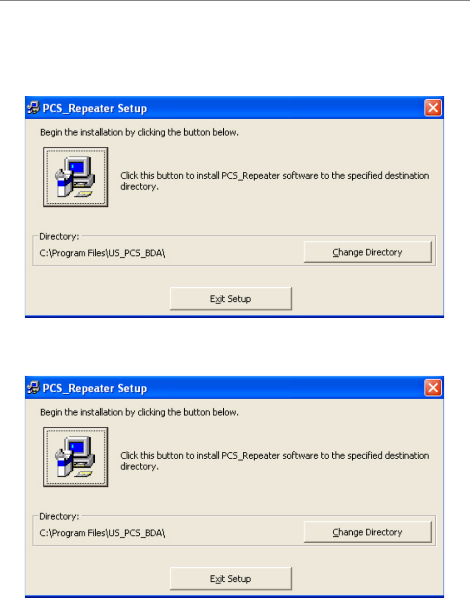
Program automatically creates a default directory to install the program in. If you wish to change
the installation directory, select “Change Directory” button to manually create a directory.
Click icon on screen to begin installation.
ADCP-75-237 • Issue 1 • 8/2007 • Section 3: Graphical User Interface
Page 3-3
© 2007, ADC Telecommunications, Inc.
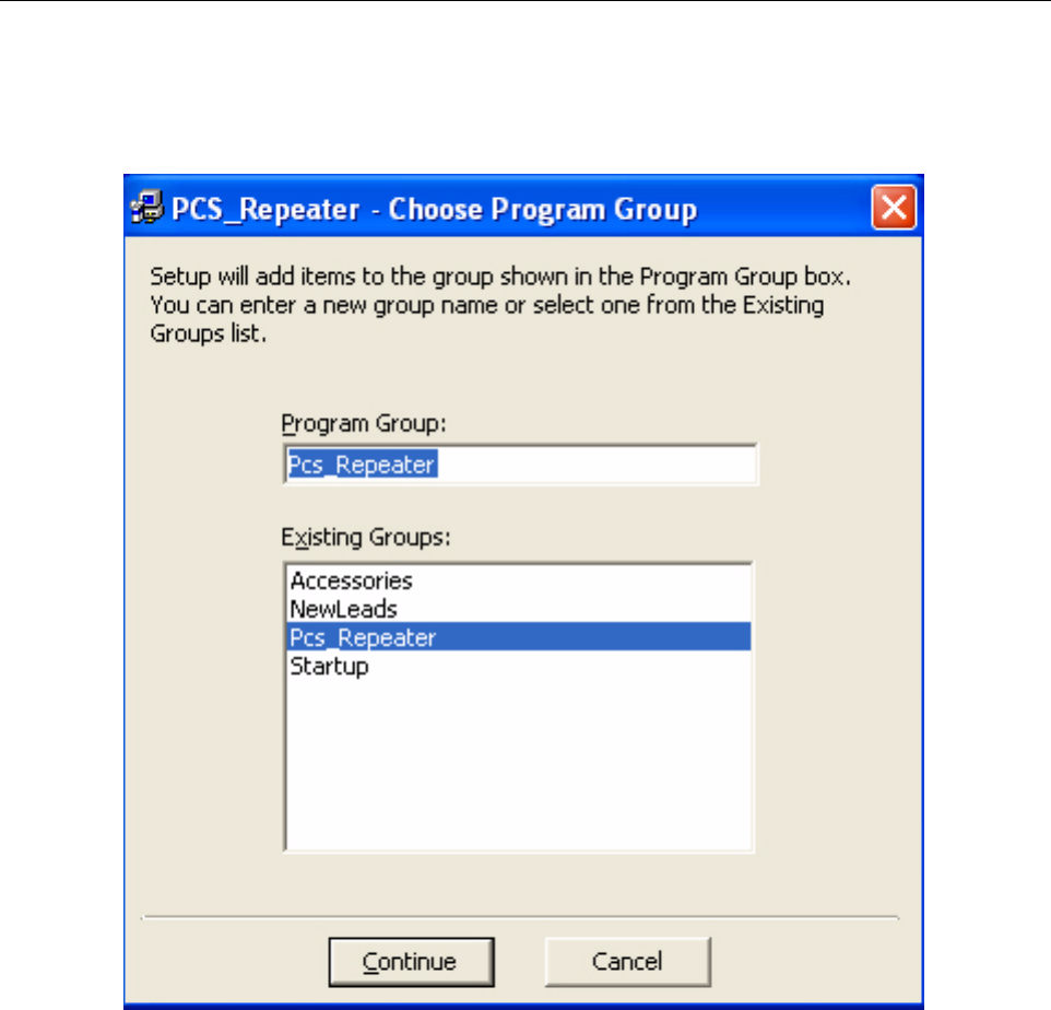
Choose a Program Group where program is to be installed. By default, the program creates a
new program group named “Pcs_Repeater”. Click “Continue” button.
ADCP-75-237 • Issue 1 • 8/2007 • Section 3: Graphical User Interface
Page 3-4
© 2007, ADC Telecommunications, Inc.
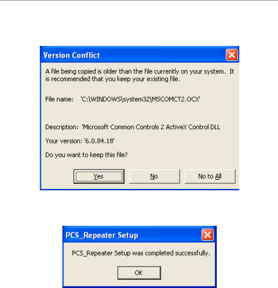
If this software program is using an older window database there is a version conflict. Keep the
original file by clicking “Yes”
Successful installation completed. Click “OK” button.
The window will automatically close. You do not need to re-start the computer to begin using
the program.
ADCP-75-237 • Issue 1 • 8/2007 • Section 3: Graphical User Interface
Page 3-5
© 2007, ADC Telecommunications, Inc.
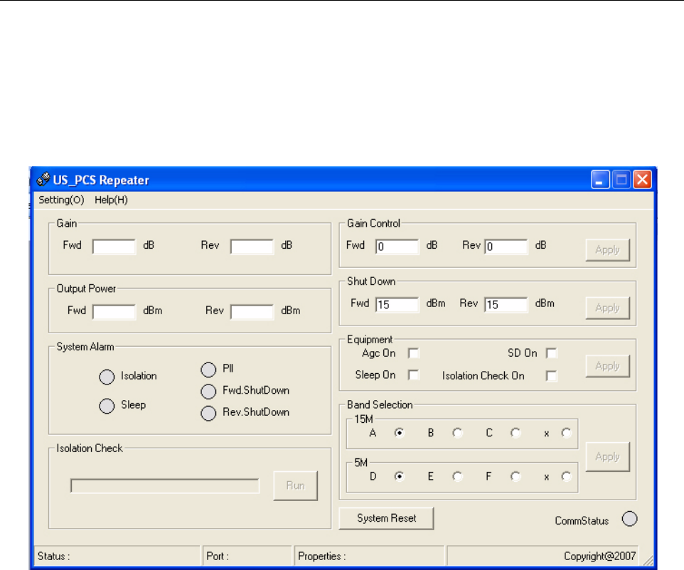
2 OPERATING THE SOFTWARE
After installing the program, run program by going to Windows “Start” menu -> “Program” ->
Pcs_Repeater program group. Click “Pcs_Repeater” to start program. The following screen
displays the start window of the program.
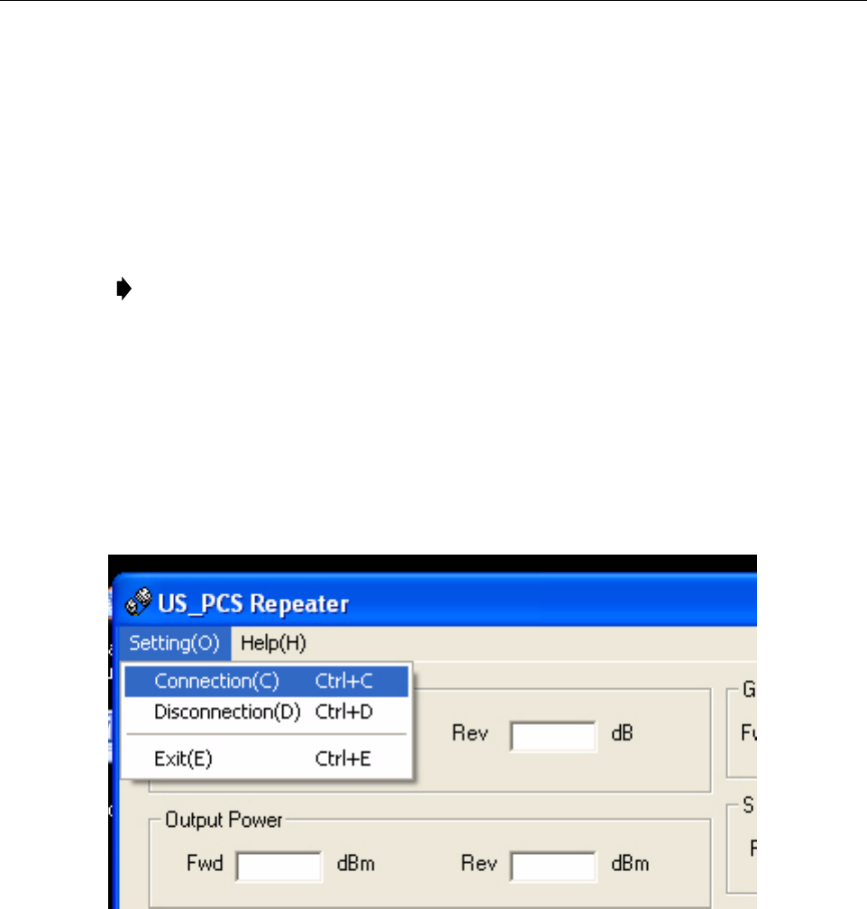
2.1 Menu Information
- Setting:
• Connection: options for connecting the PC and the Repeater system by RS232 port
• Disconnection: Disconnect the RS232 port
• Exit: Exit from the software
- Help: Show PC information/program information
ADCP-75-237 • Issue 1 • 8/2007 • Section 3: Graphical User Interface
Page 3-6
© 2007, ADC Telecommunications, Inc.
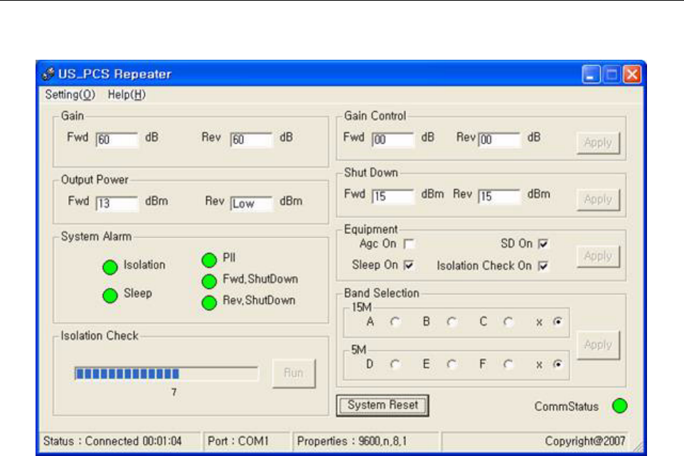
2.2 Control Panel Information
- Gain: Show current gain of the repeater system
- Output Power: Show current output power
- System Alarm: Show current alarm status
• Isolation: When there is an error, Fwd.ShutDown, Rev.ShutDown, and Isolation signal
buttons turn red.
• PLL: When there is an error on PLL, the signal button turns red.
• Fwd.ShutDown: When output power is equal to or higher than the registered value, the
signal button turns red.
• Rev.ShutDown: When output power is equal to or higher than the registered value, the
signal button turns red.
-
Isolation Check:
“RUN” button is active. Pressing the “RUN” button starts the isolation check.
When the “Isolation Check On” check box from “Equipment Box” section is checked, the
Repeater system starts the isolation check three seconds after the BDA is connected. If you do
not press the button for three seconds the isolation check is automatically started.
If the results
produce an error, System Alarm LEDs indicate the error.
- Gain Control: Input attenuation value, to control gain of the repeater system. Press “Send”
button to apply the value to the system.
- Shut Down: Input shut down level of the repeater system. Press “Send” button to apply the
value to the system.
ADCP-75-237 • Issue 1 • 8/2007 • Section 3: Graphical User Interface
Page 3-7
© 2007, ADC Telecommunications, Inc.
- Equipment:
• AGC ON/OFF: Select to apply this option to the system and press “Send” to apply the
selection.
• Sleep ON/OFF: Select to apply this option to the system and press “Send” to apply the
selection.
• SD (shut down) ON/OFF: Select to apply this option to the system and press “Send” to
apply the selection.
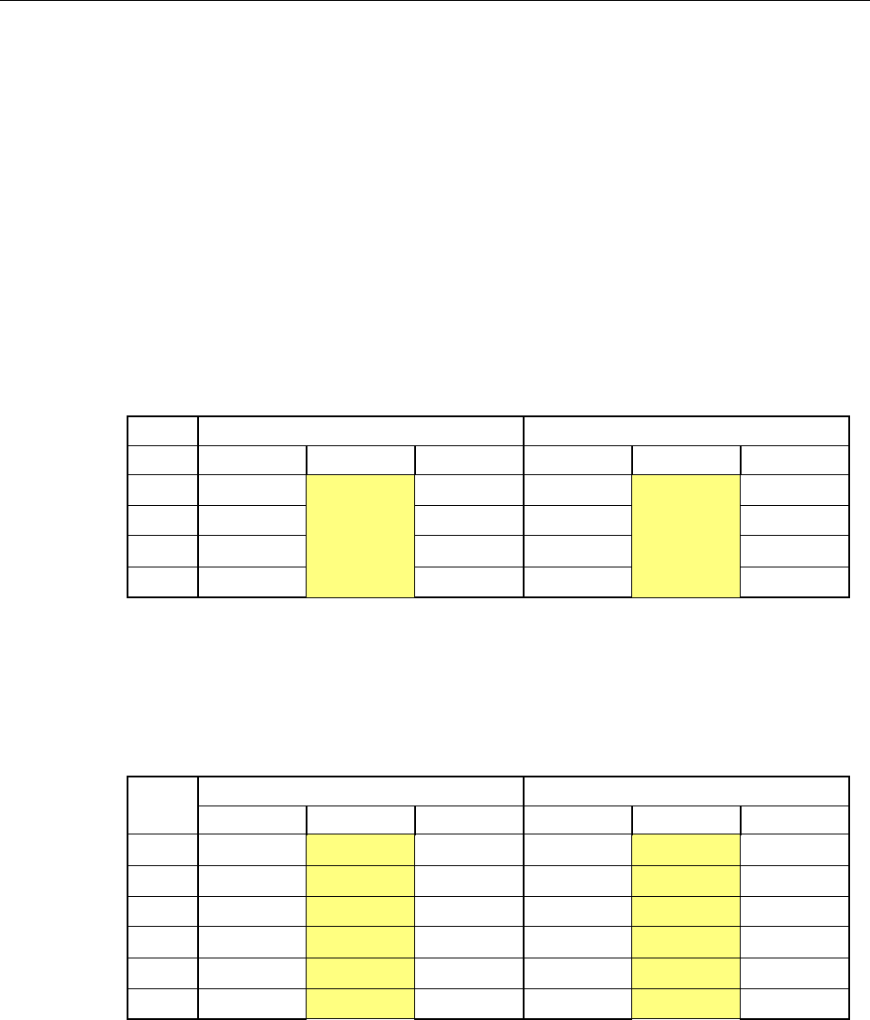
850MHz Band Selection:
• A”+A/A/x: 12.5MHz path band A”+A, A, or no selection (x)
• B/B’/x: 12.5MHz path band B, B’, or no selection (x)
• Select to apply these options to the system and press “Apply” to apply the selections. See
below for factory set frequencies per band.
BAND TX RX
Select start Freq. Lo Freq. stop Freq. start Freq. Lo Freq. stop Freq.
A”+A 869
951.5
880 824
951.5
835
B880 890 835 845
A’ 890 891.5 845 846.5
B’ 891.5 894 846.5 849
1900MHz Band Selection:
• A/B/C/x: 15MHz path band A,B,C, or no selection (x)
• D/E/F/x: 5MHz path band D,E,F, or no selection (x)
• Select to apply these options to the system and press “Apply” to apply the selections. See
below for factory set frequencies per band.
BAND
TX RX
start Freq. stop Freq. start Freq. stop Freq.
A1930.625 1937.5 1944.375 1850.625 1857.5 1864.375
D1945.625 1947.5 1949.375 1865.625 1867.5 1869.375
B1950.625 1957.5 1964.375 1870.625 1877.5 1884.375
E1965.625 1967.5 1969.375 1885.625 1887.5 1889.375
F1970.625 1972.5 1974.375 1890.625 1892.5 1894.375
C1975.625 1982.5 1989.375 1895.625 1902.5 1909.375
- System Reset: Press this to re-set the system.
- CommStatus: Blinking -> communicating
Gray -> Shut communication
ADCP-75-237 • Issue 1 • 8/2007 • Section 3: Graphical User Interface
Page 3-8
© 2007, ADC Telecommunications, Inc.
2.3 Status Bar
- Status:
Window bottom line Status shows connected/disconnected status and time being
connected. Upper right side check box will also denote Communication status of connected
activity.
- Port: Window bottom line Port shows the connected port number
- Properties: Window bottom line Properties shows the property information.
Note: You must install a USB driver to use the USB port. After installing the driver, the
software recognizes the USB driver as a normal com port.
3 SET COMMUNICATION PORT PROPERTIES
Communication parameters must be set before the computer can communicate with the repeater.
All GUI controls can be used after connecting the repeater system using the following
“Connection” procedure.
1. Open “Setting” -> “Connection”
2. Port Properties window opens.
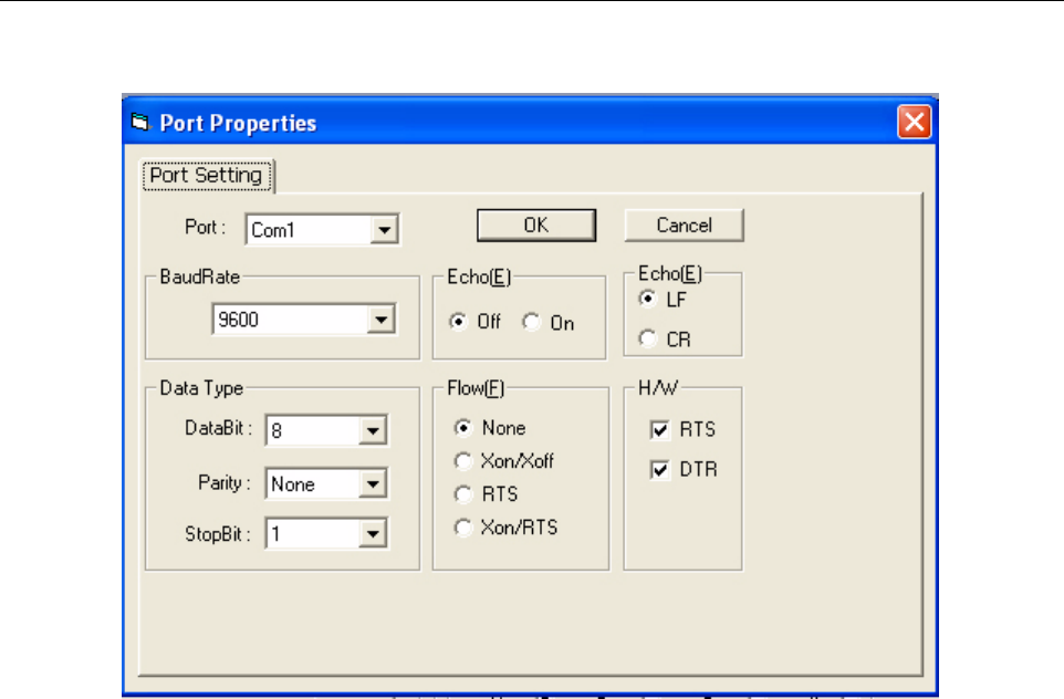
ADCP-75-237 • Issue 1 • 8/2007 • Section 3: Graphical User Interface
Page 3-9
© 2007, ADC Telecommunications, Inc.
- Port: Select serial port number from 1 to 16
- BaudRate: Select Baud rate “9600”bps
- Data Type: DataBit: Select “8”bit, Parity: Select “None”, StopBit: Select “1”
- Echo: Select “Off”, “LF”
- Flow: Select “None”
- H/W: Select both.
All options may use default settings except for “Port”. You must select correct port # that the
computer is connected to the equipment with.
After finishing the selection, press “OK” to save and return to the main setting window. If you
press “Cancel”, the selections are not be saved and you are returned to the Port Properties
window. If the selected port is not correct, the program displays “It's not available” on the
screen and requests that you select another port.
ADCP-75-237 • Issue 1 • 8/2007 • Section 3: Graphical User Interface
Page 3-10
© 2007, ADC Telecommunications, Inc.
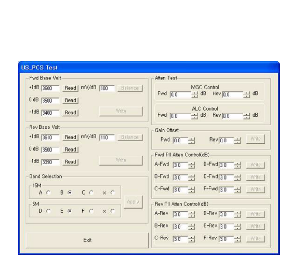
4 US_PCS TEST SCREEN
The Testing screen is opened by pressing the “F5” Function key. This window is used to test
each attenuation, and test band selection or set PLL.
4.1 Fwd Base Volt
Input 0dB signal to the repeater system, and click 0dB “Read” button. This will read the
forward path voltage and show in the text box.
Input +1dB signal to the repeater system, and click +1dB-”Read” button. This will read the
forward path voltage and show in the text box.
Input –1dB signal to the repeater system, and click -1dB-”Read” button. This will read the
forward path voltage and show in the text box.
After all three values are read, “Balance” button will become active. By pressing the “Balance”
button, the program automatically calculates the voltage difference of 0dB, +1dB, and -1dB
situation, and print in the text box beside the “Balance” button.
After the balance voltage value has been printed in the text box, “Write” button will become
active. Pressing the “Write” button will save the voltage values to the repeater system memory.

ADCP-75-237 • Issue 1 • 8/2007 • Section 3: Graphical User Interface
Page 3-11
© 2007, ADC Telecommunications, Inc.
4.2 Rev Base Volt
Repeat the FWD Base Volt set-up for the Rev Base Volt (Reverse Base Voltage).
4.3 Band Selection
850MHz
1900MHz
A/B/C/x: 15MHz path band A, B, C, or no selection (x)
D/E/F/x: 5MHz path band D, E, F, or no selection (x)
Select to apply these options to the system and press “Apply” to apply the selections.
4.4 Attenuation Test: MGC / ALC Control
Press up/down arrow key to adjust the Manual Gain Control in 0.5dB increments.
Press up/down arrow key to adjust the Automatic Level Control in 0.5dB increments.
4.5 Gain Offset Box
FWD/REV gain offset can be changed in 0.5dB steps by using Up/Down Key.
4.6 Fwd PLL Attenuation Control
Each band can be selected to have 0.0~9.5dB attenuation. This function can test gain flatness.
Press “Write” to apply setting.
4.7 Rev Pll Attenuation Control
Same as FWD PLL Attenuation Control
If you have finished each function testing, press “Exit” to exit the testing mode and reset the
system.

ADCP-75-237 • Issue 1 • 8/2007 • Section 3: Graphical User Interface
Page 3-12
© 2007, ADC Telecommunications, Inc.
Blank

ADCP-75-237 • Issue 1 • 8/2007 • Section 4: GENERAL INFORMATION
Page 4-1
© 2007, ADC Telecommunications, Inc.
SECTION 4: GENERAL INFORMATION
Content Page
1 WARRANTY/SOFTWARE . . . . . . . . . . . . . . . . . . . . . . . . . . . . . . . . . . . . . . . . . . . . . . . . . . . . . . . . . . . . . . . . . .5-1
2 SOFTWARE SERVICE AGREEMENT. . . . . . . . . . . . . . . . . . . . . . . . . . . . . . . . . . . . . . . . . . . . . . . . . . . . . . . . . . .5-1
3 REPAIR/EXCHANGE POLICY . . . . . . . . . . . . . . . . . . . . . . . . . . . . . . . . . . . . . . . . . . . . . . . . . . . . . . . . . . . . . . .5-1
4 REPAIR CHARGES . . . . . . . . . . . . . . . . . . . . . . . . . . . . . . . . . . . . . . . . . . . . . . . . . . . . . . . . . . . . . . . . . . . . . .5-2
5 REPLACEMENT/SPARE PRODUCTS . . . . . . . . . . . . . . . . . . . . . . . . . . . . . . . . . . . . . . . . . . . . . . . . . . . . . . . . . .5-2
6 RETURNED MATERIAL . . . . . . . . . . . . . . . . . . . . . . . . . . . . . . . . . . . . . . . . . . . . . . . . . . . . . . . . . . . . . . . . . . .5-2
_________________________________________________________________________________________________________
1 WARRANTY/SOFTWARE
(This is a boilerplate section that appears in many manuals. Delete this paragraph.)
The Product and Software warranty policy and warranty period for all ADC Products is published
in ADC’s Warranty/Software Handbook. Contact the Technical Assistance Center at
1-800-366-3891, extension 73476 (in U.S.A. or Canada) or 952-917-3476 (outside U.S.A. and
Canada) for warranty or software information or for a copy of the Warranty/Software Handbook.
2 SOFTWARE SERVICE AGREEMENT
ADC software service agreements for some ADC Products are available at a nominal fee.
Contact the Technical Assistance Center at 1-800-366-3891, extension 73476 (in U.S.A. or
Canada) or 952-917-3476 (outside U.S.A. and Canada) for software service agreement
information.
3 REPAIR/EXCHANGE POLICY
All repairs of ADC Products must be done by ADC or an authorized representative. Any
attempt to repair or modify ADC Products without written authorization from ADC voids the
warranty.
If a malfunction cannot be resolved by the normal troubleshooting procedures, call the
Technical Assistance Center at 1-800-366-3891, extension 73476 (in U.S.A. or Canada) or
952-917-3476 (outside U.S.A. and Canada). A telephone consultation can sometimes resolve a
problem without the need to repair or replace the ADC Product.
If, during a telephone consultation, ADC determines the ADC Product needs repair, ADC will
authorize the return of the affected Product for repair and provide a Return Material
Authorization number and complete return shipping instructions. If time is critical, ADC can
arrange to ship the replacement Product immediately. In all cases, the defective Product must be
carefully packaged and returned to ADC.

ADCP-75-237 • Issue 1 • 8/2007 • Section 4: GENERAL INFORMATION
Page 4-2
© 2007, ADC Telecommunications, Inc.
4 REPAIR CHARGES
If the defect and the necessary repairs are covered by the warranty, and the applicable warranty
period has not expired, the Buyer’s only payment obligation is to pay the shipping cost to return
the defective Product. ADC will repair or replace the Product at no charge and pay the return
shipping charges.
Otherwise, ADC will charge a percentage of the current Customer Product price for the repair
or NTF (No Trouble Found). If an advance replacement is requested, the full price of a new unit
will be charged initially. Upon receipt of the defective Product, ADC will credit Buyer with 20
percent of full price charged for any Product to be Out-of-Warranty. Products must be returned
within thirty (30) days to be eligible for any advance replacement credit. If repairs necessitate a
visit by an ADC representative, ADC will charge the current price of a field visit plus round trip
transportation charges from Minneapolis to the Buyer’s site.
5 REPLACEMENT/SPARE PRODUCTS
Replacement parts, including, but not limited to, button caps and lenses, lamps, fuses, and patch
cords, are available from ADC on a special order basis. Contact the Technical Assistance Center
at 1-800-366-3891, extension 73476 (in U.S.A. or Canada) or 952-917-3476 (outside U.S.A.
and Canada) for additional information.
Spare Products and accessories can be purchased from ADC. Contact Sales Administration at
1-800-366-3891, extension 73000 (in U.S.A. or Canada) or 1-952-938-8080 (outside U.S.A.
and Canada) for a price quote and to place your order.
6 RETURNED MATERIAL
Contact the ADC Product Return Department at 1-800-366-3891, extension 73748 (in U.S.A. or
Canada) or 952-917-3748 (outside U.S.A. and Canada) to obtain a Return Material
Authorization number prior to returning an ADC Product.
All returned Products must have a Return Material Authorization (RMA) number clearly
marked on the outside of the package. The Return Material Authorization number is valid for 90
days from authorization.
13944-O
PHONE:
WRITE:
PRODUCT INFORMATION AND TECHNICAL ASSISTANCE:
ADC Telecommunications (S’PORE) PTE, LTD;
100 Beach Road, #18-01, Shaw Towers.
Singapore 189702.
ADC Telecommunications, INC
PO Box 1101,
Minneapolis, MN 55440-1101, USA
ADC European Customer Service, INC
Belgicastraat 2,
1930 Zaventem, Belguim
connectivity.tac@adc.com
wireless.tac@adc.com
euro.tac@adc.com
asiapacific.tac@adc.com
U.S.A. or CANADA
Sales: 1-800-366-3691
Extension 73000
Technical Assistance: 1-800-366-3891
Connectivity Extension: 73475
Wireless Extension: 73476
EUROPE
Sales Administration: +32-2-712-65 00
Technical Assistance: +32-2-712-65 42
EUROPEAN TOLL FREE NUMBERS
Germany: 0180 2232923
UK: 0800 960236
Spain: 900 983291
France: 0800 914032
Italy: 0800 782374
ASIA/PACIFIC
Sales Administration: +65-6294-9948
Technical Assistance: +65-6393-0739
ELSEWHERE
Sales Administration: +1-952-938-8080
Technical Assistance: +1-952-917-3475
Contents herein are current as of the date of publication. ADC reserves the right to change the contents
without prior notice. In no event shall ADC be liable for any damages resulting from loss of data,
loss of use, or loss of profits and ADC further disclaims any and all liability for indirect, incidental,
special, consequential or other similar damages. This disclaimer of liability applies to all products,
publications and services during and after the warranty period.