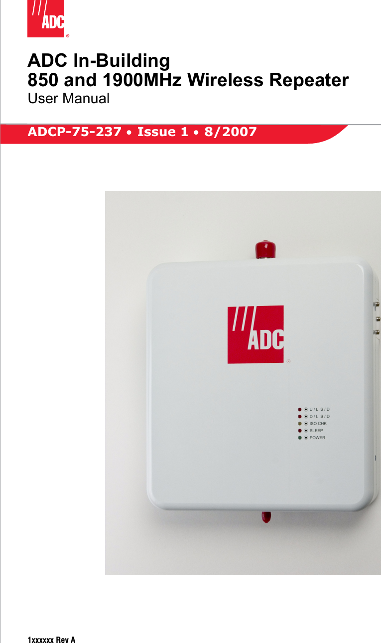
ADC Telecommunications RPT080AA ADC's In-Building Wireless Repeater BDA - Cellular User Manual 75237p1
ADC Telecommunications Inc ADC's In-Building Wireless Repeater BDA - Cellular 75237p1
Contents
- 1. User manual 1
- 2. User manual 2
- 3. User manual 3
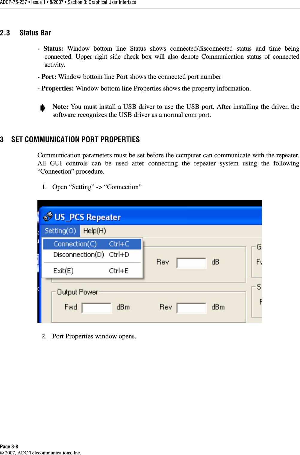
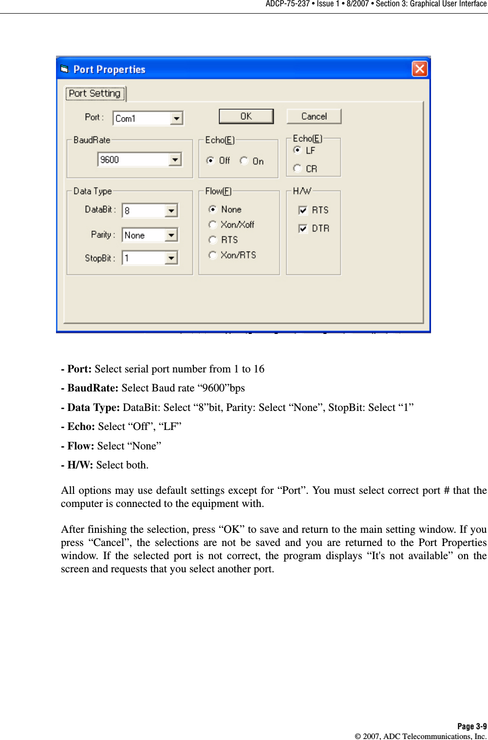
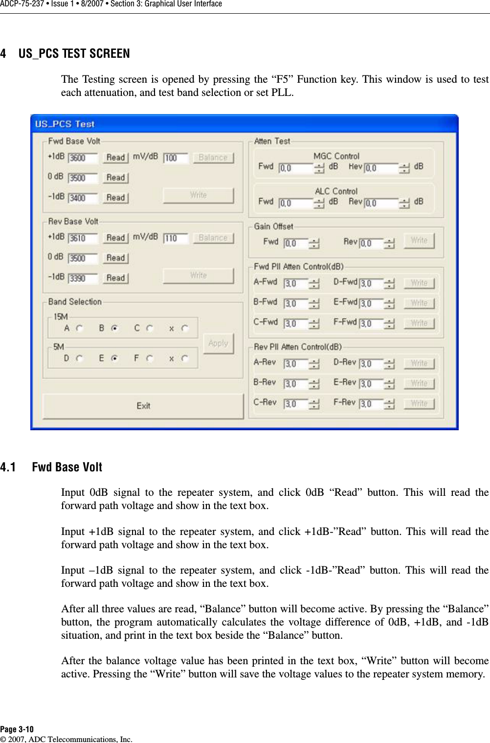
User manual 1