ADC Telecommunications S2195-011 InterReach Spectrum Remote Access Unit User Manual 77222p2 Test
ADC Telecommunications Inc. InterReach Spectrum Remote Access Unit 77222p2 Test
Contents
- 1. Installation Guide
- 2. Users Manual
Installation Guide
InterReach Spectrum™
Remote Access Unit
Installation Guide
TECP-77-222 · Issue 2 · March 2014
©2014TEConnectivity,Inc.AllRightsReserved.InformationcontainedinthisdocumentiscompanyprivatetoTEConnectivityLtd.,andshallnotbemodified,used,
copied,reproducedordisclosedinwholeorinpartwithoutthewrittenconsentofTE.
FlexWave,FlexWavePrism,InterReachSpectrum,InterReachUnison,UniversalRadioHead,TEConnectivity,andTEconnectivity(logo)aretrademarks.Allotherlogos,
productsand/orcompanynamesreferredtohereinmightbetrademarksoftheirrespectiveowners.
Contentshereinarecurrentasofthedateofpublication.TEreservestherighttochangethecontentswithoutpriornotice.Shouldthecontentofprinteduser
documentationshippedwithproductdifferfromdocumentationprovidedonaproductCD(inclusiveoftheassociatedHelpmodules),theprinteduserdocumentation
supersedesthedocumentationontheproductCD.InnoeventshallTEbeliableforanydamagesresultingfromlossofdata,lossofuse,orlossofprofits,andTEfurther
disclaimsanyandallliabilityforindirect,incidental,special,consequentialorothersimilardamages.Thisdisclaimerofliabilityappliestoallproducts,publicationsand
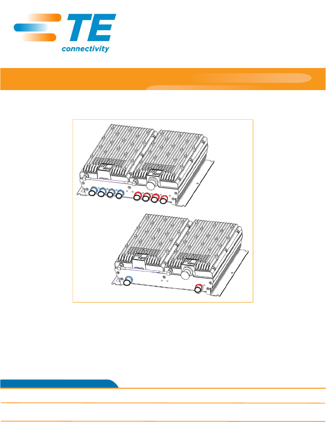
ThisinstallationguideprovidesinstallationinstructionsforInterReachSpectrum®RemoteAccessUnits(RAUs).
Preliminary - for standards compliance testing only.
Not for distribution to customer.
Main Remote Access Unit
Secondary Remote Access Unit

Page2InterReachSpectrumRemoteAccessUnitInstallationGuide‐PreliminaryNotforDistribution
©2014 TEConnectivityLtd. TECP‐77‐222Issue2 • 300001759666RevB•March2014
Table1liststhestandardRAUsthataresupportedinthisdocument.
RevisionHistory
DocumentCautionsandNotes
Twotypesofmessages,identifiedbelow,appearinthetext:
CAUTION! Cautionsindicateoperationsorstepsthatcouldcausepersonalinjury,induceasafetyprobleminamanageddevice,
destroyorcorruptinformation,orinterruptorstopservices.
NOTE: Notescontaininformationaboutspecialcircumstances.
Table1. SupportedSpectrumStandardRemoteAccessUnits
CatalogNumberDescription
StandardRAUs
SPT‐M1‐8519‐1Spectrum,850‐1900MainRAU
SPT‐S1‐8519‐22 Spectrum,850Path2‐1900Path2SecondaryRAU
SPT‐S1‐8090‐1*Spectrum,800‐900SMRSecondaryRAU
SPT‐S1‐80AWS‐1*Spectrum,800‐2100AWSPath1SecondaryRAU
SPT‐S1‐8019‐22*Spectrum,800Path2‐1900Path2SecondaryRAU
SPT‐S2‐70AWS‐1‐SISO Spectrum,700SISO‐2100AWSPath1SECRAU,UpperC‐LowerABC
SPT‐S2‐70AWS‐22‐SISO Spectrum,700Path2SISO‐2100AWSPath2SECRAU,UpperC‐LowerABC
SPT‐S1‐7070‐1‐MIMO Spectrum,700MIMOSecondaryRAU,UpperC‐LowerABC
SPT‐M1‐AWS19‐11 Spectrum,2100AWSPath1‐1900Path1MainRAU
SPT‐S1‐AWS19‐12 Spectrum,2100AWSPath1‐1900Path2SecondaryRAU
SPT‐S1‐2121‐1‐MIMO Spectrum,2100AWSMIMOSecondaryRAU
HighPowerRAUs
SPT‐M3‐8019‐31‐HP*Spectrum,800Path3‐1900HPPath1MainRAU
SPT‐M3‐8519‐11‐HP Spectrum,850Path1‐1900HPPath1MainRAU
SPT‐S3‐2626‐12‐HP Spectrum,2600HPPath1‐2600HPPath2SecondaryRAU
SPT‐S3‐70AWS‐11‐HP Spectrum,700Path1uC/LABC‐AWSHPPath1SecondaryRAU
SPT‐S3‐70AWS‐22‐HP Spectrum,700Path2uC/LABC‐AWSHPPath2SecondaryRAU
SPT‐S3‐8019‐22‐HP*Spectrum,800Path2‐1900HPPath2SecondaryRAU
SPT‐S3‐8519‐22‐HPSPT‐
S3‐8019‐22‐HP
Spectrum,850Path2‐1900HPPath2SecondaryRAU
*ThisRAUisClassBSignalBooster;see“Part90SignalBoosters”onpage 26.
Issue DocumentDate TechnicalUpdates
1February2013 Initialrelease.
2March2014 •Addssupportforthe2600HPPath1‐2600HPPath2SecondaryRAU;the800Path3‐1900HP
Path1MainRAU,andthePath2‐1900HPPath2SecondaryRAU.
•Addstorqueinformation;see“ConnecttheIFEUtotheMRAU”onpage 11and“Connectthe
MRAUtoSRAUs”onpage 12.

InterReachSpectrumRemoteAccessUnitInstallationGuide‐PreliminaryNotforDistribution Page3
TECP‐77‐222Issue2 • 300001759666RevB•March2014 ©2014 TEConnectivityLtd.
PRODUCTOVERVIEW
InterReachSpectrumsupportsupto8bandsinasinglesystem.Eachantennalocationsupportsthosebandsin
modular,grouppairings.EachlocationincludesaMainRemoteAccessUnit(MRAU)thatcanpoweruptothree
additionalSecondaryRAUs(SRAUs),eachofwhichsupporttwopoweramplifierpairsforatotalofeight
amplifiers.MRAUsandSRAUsaregroupedlogicallybasedoncommonserviceprovidergroupingsandinclude:
850/1900,700/700MIMO,800/900SMR,700SISO/AWS,and800/AWS.Addingfrequencyisassimpleas
plugginginanSRAUtotheexistingMRAU(seeTable 4onpage 17throughTable 6onpage 19in“Specifications”).
RAUsareavailableintwodifferentoutputpoweroptions:StandardandHighPower.Thesecanbe“mixedand
matched”onasystemtomeetthespecificneedsofavenue.
SinceSpectrumcanbeconfiguredtosupportasmanyasfourcascadedrunsofsixteentotalExpansionModule
Groups,thesystemconfigurationpossibilitiesareseeminglyendlessandcanscaletosinglesystemsthatinclude
asmanyas128MRAUlocations,witheachofthoselocationssupportingbetweenoneandeightRFbands.And
eachofthosebandlocationsoffers26dBm(P1dB)or31dBm(P1dB)ofoutputpowerbasedonselecting
standardorHighPower(HP)RAUs.
ThesystemmaybescaledtoaddnewbandsorRAUlocationsitesas‐neededandoffersgreatserviceflexibility
andperformancerelativetoshared,wide‐bandamplifiersystems.Eachserviceprovidermaycontroltheirband
ofinterestandenjoythepredictabilityinconsistentserviceateachRAUlocationindependentofwhatother
operatorsaredoingorthelengththesignaltravelstotheservicearea.
TheRAUsaretypicallymountedaboveceilingtilesorinout‐of‐sightlocationsascloseaspossibletotheservice
area.
Page4InterReachSpectrumRemoteAccessUnitInstallationGuide‐PreliminaryNotforDistribution
©2014 TEConnectivityLtd. TECP‐77‐222Issue2 • 300001759666RevB•March2014
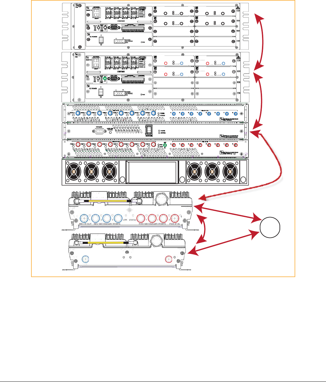
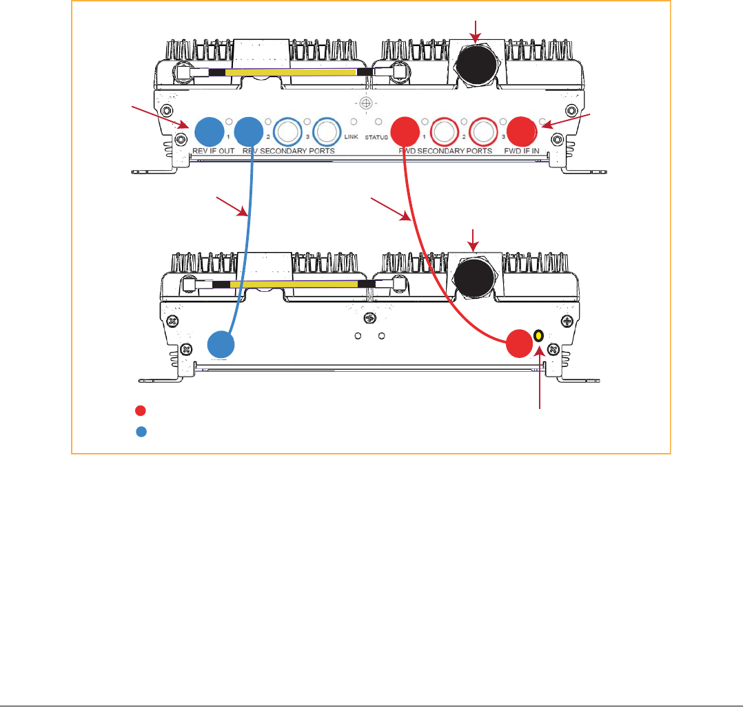
Figure 1illustrateshowRFandIFsignalsaresentbetweenSpectrumunitsandmodules.
NOTE: AllFWDportsonallModulesarecolor‐codedredandallREVportsarecolor‐codedblue,whichmakestheDRU,IFEU,
andRAUcablingprocesseasiertocomplete.
Figure1.REVandFWDSignalsfortheRAU
NOTE: ThisbookreferstotheOmniAntenna(4214‐0727),whichistheantennathatTEConnectivityrecommends.Other
antennasmaybeused.ForfurtherinformationontheOmniAntenna,see“OmniAntennaSpecifications”onpage 25.
LINK STATUS
SECONDARY
REV
SECONDARY
FWD
SECONDARY
REV
SECONDARY
FWD
LINK STATUS
REV IF OUT REV SECONDARY PORTS
1 2 3
FWD SECONDARY PORTS
1 2 3
FWD IF IN
LINK STATUS
Host
SRAU
MRAU
Power
Supply
IFEU
DRU
IF
RF
Omni
Antenna
R
F
R
F
x
x x
xx
x x
xx
x x
xx
x
x x
xx
x x
xx
x x
xx
x
REMOTE
SYSTEM II
IF DART
XXXXXXXXXX
BW XX MHz
FWD
IF OUT
REV
IF IN
PWR
STATUS
REMOTE
IF DART
XXXXXXXXXX
BW XX MHz
FWD
IF OUT
REV
IF IN
PWR
STATUS
REMOTE
IF DART
XXXXXXXXXX
BW XX MHz
FWD
IF OUT
REV
IF IN
PWR
STATUS
REMOTE
IF DART
XXXXXXXXXX
BW XX MHz
FWD
IF OUT
REV
IF IN
PWR
STATUS
REMOTE
IF
IF
HOST
SYSTEM II
RF DART
SMR900
FWD 935-940
REV 896-901
REV
RF OUT
FWD
RF IN
FWD NOT TO
EXCEED +5 dBm
PWR
STATUS
HOST
RF DART
SMR900
FWD 935-940
REV 896-901
REV
RF OUT
FWD
RF IN
FWD NOT TO
EXCEED +5 dBm
PWR
STATUS
HOST
RF DART
SMR900
FWD 935-940
REV 896-901
REV
RF OUT
FWD
RF IN
FWD NOT TO
EXCEED +5 dBm
PWR
STATUS
HOST
RF DART
SMR900
FWD 935-940
REV 896-901
REV
RF OUT
FWD
RF IN
FWD NOT TO
EXCEED +5 dBm
PWR
STATUS
HOST
NOTE: Units shown are not to scale.
InterReachSpectrumRemoteAccessUnitInstallationGuide‐PreliminaryNotforDistribution Page5
TECP‐77‐222Issue2 • 300001759666RevB•March2014 ©2014 TEConnectivityLtd.
MainRemoteAccessUnits
TheMainRemoteAccessUnit(MRAU)receivesFWDIFsignalsfromanIFExpansionUnit(IFEU),whichispart
oftheSpectrumExpansionModuleGroup,using75CATVcable.TheMRAUconvertstheIFsignalstoRFand
sendsthemtoapassiveRFantennausing50coaxialcable.TheMRAUalsoreceivesconfigurationinformation
andpowerfromandsendsitsstatusinformationtotheIFEU.
TheMRAUreceivesREVRFsignalsfromapassiveRFantennausing50coaxialcable.Itconvertsthesignalsto
IFandsendsthemtotheIFEUusing75CATVcable.
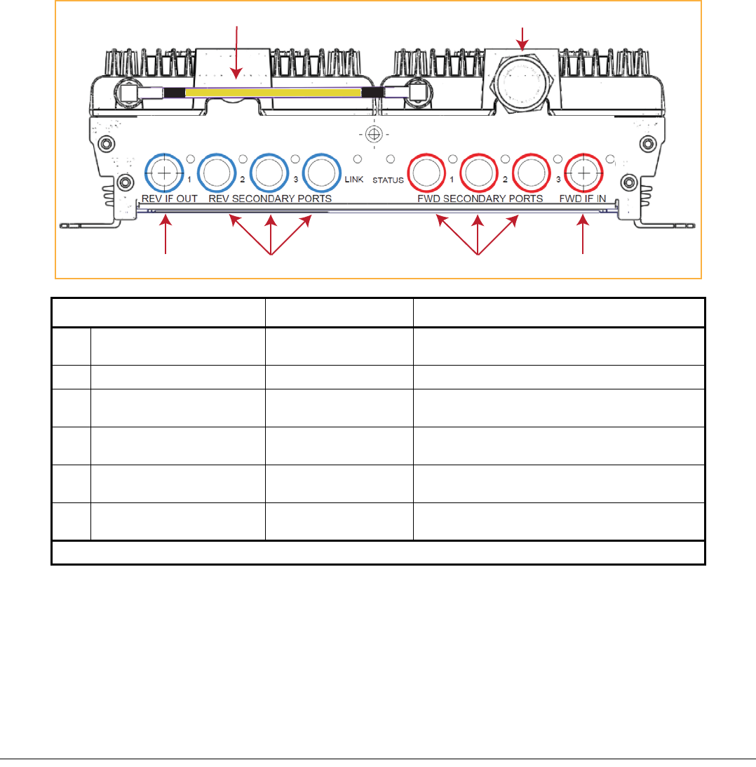
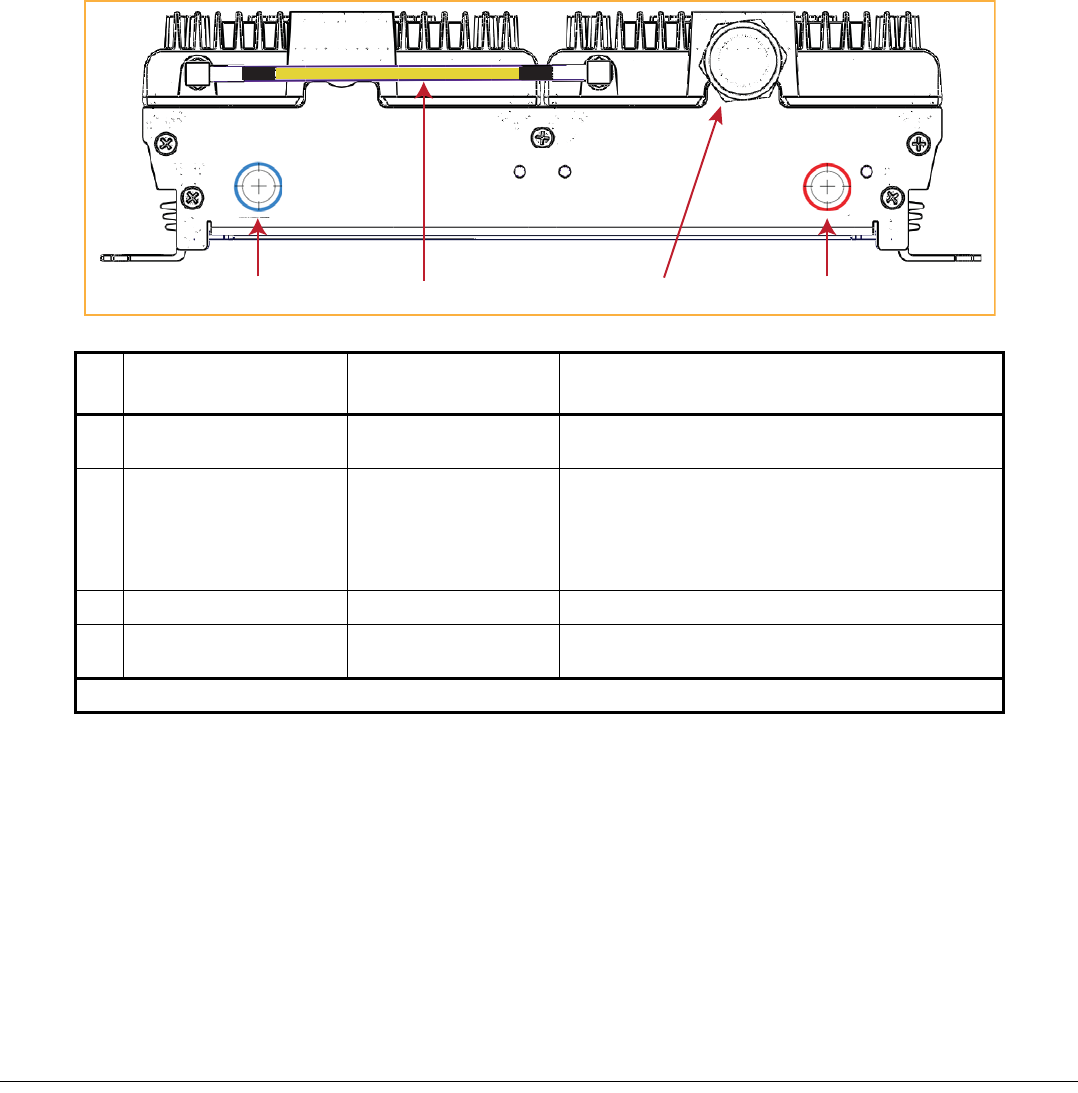
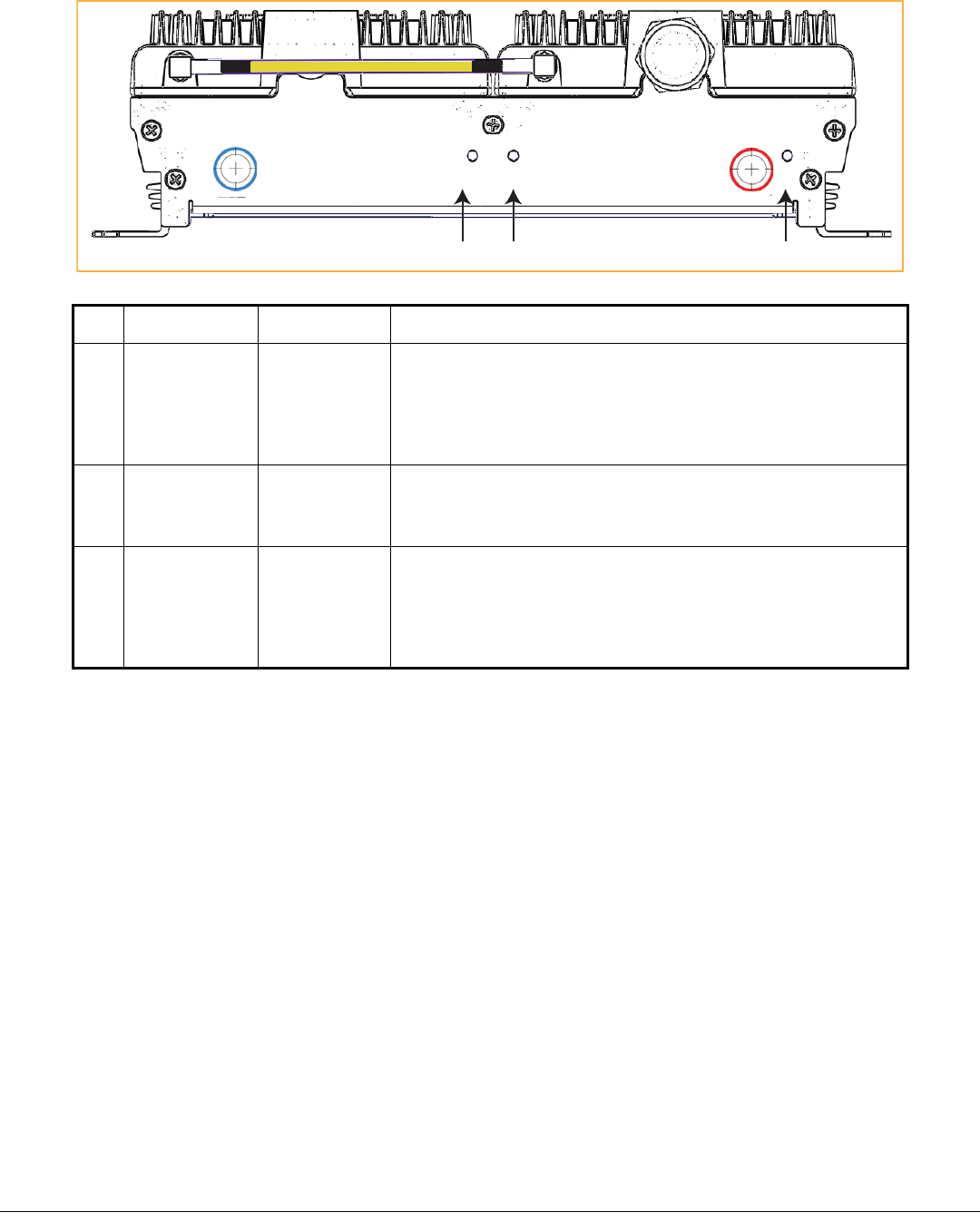
MRAUPorts,Cable,andConnectors
Ref# Component Device Function
1RFSubMiniatureversionA
(SMA)cable(1)
50RFSMA‐to‐SMAcable ConnectstwoRFbandstogetherwhenthereisonly
oneN‐typeconnectorontheRAU.
2 Antennaport(s) 50N‐typeconnector Connectstoanantenna.SeeTable 2onpage 9.
3FWDIFINconnector Fconnectorport ConnectstotheIFEUFWDModuleIFOUTconnector
viaCATVcable.
4FWD
SECONDARYPORTS(1‐3) Fconnectorports ConnecttoaSRAUSECONDARYFWDconnectorvia
CATVcable.
5REVSECONDARYPORTS(1‐3) Fconnectorports ConnecttoaSRAUSECONDARYREVconnectorvia
CATVcable.
6REVIFOUTconnector Fconnectorport ConnectstotheIFEUREVModuleIFINconnectorvia
CATVcable.
(1) TheAWS/PCSMRAUsdoNOThaveanRFSMAcable—theyhavetwoAntennaports.
REV IF OUT REV SECONDARY PORTS
1 2 3
FWD SECONDARY PORTS
1 2 3
FWD IF IN
LINK STATUS
1 2
36 54
Page6InterReachSpectrumRemoteAccessUnitInstallationGuide‐PreliminaryNotforDistribution
©2014 TEConnectivityLtd. TECP‐77‐222Issue2 • 300001759666RevB•March2014
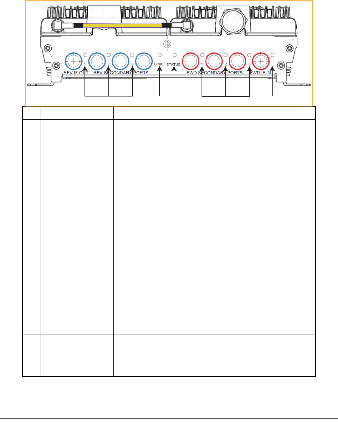
MRAULEDs
Ref#LED LEDColor Description
1FWDSECONDARYPORT
(1‐3)
•Green •Downstreamunitcorrectlyconnected;unithasnoalarmsora
Minoralarmisactive.
•BlinkingGreen • SRAUorbandissetout‐of‐service.
•Yellow •FWDcableconnectedtoSRAU,noREVcableconnected.
•Blinking
yellow
•FWDandREVcablesarenotconnectedtothesameport
number(incorrectlypaired).
•Red •Majoralarmindownstreamunit,faultlockout,orSRAU
disconnected.
•Off •NoSRAUpreviouslyconnected.
2LINK
•Green •MRAUreceivingcommunicationsfromtheIFEU.
•Red •MRAUhasnotreceivedcommunicationsfromtheIFEUformore
than90seconds.
•Off •Duringinitialpowerup,MRAUispoweringupandwaitingfor
IFEUcommunications.
3STATUS
•Green •UnithasnoalarmsoraMinoralarmisactive.
•Blinkinggreen • Unitorbandissetout‐of‐service.
•Red •Majoralarmdetected.
4REVSECONDARYPORT
(1‐3)
•Green •Downstreamunitcorrectlyconnected,unithasnoalarmsor
minoralarm
•BlinkingGreen • SRAUorbandissetout‐of‐service.
•Blinking
Yellow
•FWDandREVcablesarenotconnectedtothesameport
number(incorrectlypaired).
•Red •Majoralarmindownstreamunit,faultlockout,orSRAU
disconnected.
•Off •NoSRAUpreviouslyconnected.
5FWDIFIN
•Green •MRAUispoweredoncorrectly.
•Yellowor
Blinking
Yellow
•ThereisanIFEUFWDconnection,butthereisnoIFEUREV
connectionortheIFEUREVconnectionispairedincorrectly.
•Off •CableisnotconnectedtotheIFEUFWDport.
REV IF OUT REV SECONDARY PORTS
1 2 3
FWD SECONDARY PORTS
1 2 3
FWD IF IN
LINK STATUS
415
2 3
InterReachSpectrumRemoteAccessUnitInstallationGuide‐PreliminaryNotforDistribution Page7
TECP‐77‐222Issue2 • 300001759666RevB•March2014 ©2014 TEConnectivityLtd.
SecondaryRemoteAccessUnits
ASecondaryRemoteAccessUnit(SRAU)receivesFWDIFsignalsfromtheMRAU,using75CATVcable.The
SRAUconvertstheIFsignalstoRFandsendsthemtoapassiveRFantennausing50coaxialcable.TheSRAU,
throughtheMRAU,alsoreceivesconfigurationinformationandpowerfromandsendsitsstatusinformationto
theIFEU.
TheSRAUreceivesREVRFsignalsfromapassiveRFantennausing50coaxialcable.Itconvertsthesignalsto
IFandsendsthemtotheMRAUusing75CATVcable.
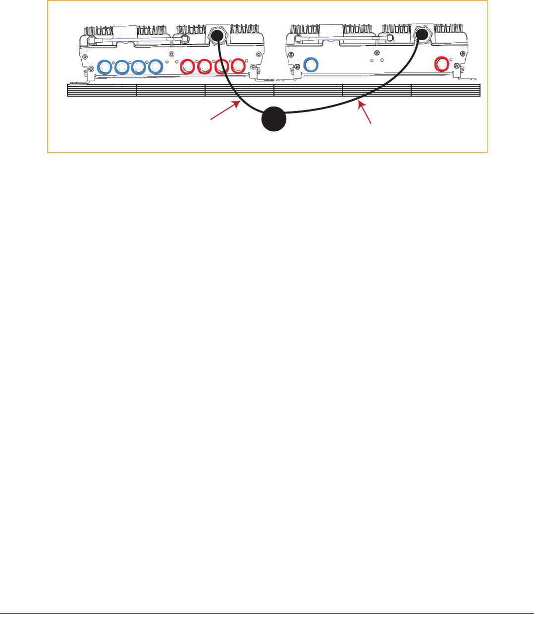
SRAUPorts,Cable,andConnectors
Ref
#
Component Device Function
1SECONDARYREVconnector Fconnectorport ConnectstooneoftheMRAUREVSECONDARYports(1‐3)
viaCATVcable.
2RFSMAcable(1)
50RFSMA‐to‐SMAcable
ConnectstwoRFbandstogetherwhenthereisonlyone
N‐typeconnectorontheRAU.
ForcaseswhenthereisanN‐typeconnectorforeachRF
band(700MIMOorPCS/AWS),therewillnotbeanSMA
cable.
3Antennaport(s) 50N‐typeconnector Connectstoanantenna.SeeTable 2onpage 9.
4SECONDARYFWDconnector Fconnectorport ConnectstooneoftheMRAUFWDSECONDARYports(1‐
3)viaCATVcable.
(1) The700MIMOSRAUdoesNOThaveanRFSMAcable;ithastwoAntennaports.
142
3
LINK STATUS
SECONDARY
REV
SECONDARY
FWD
SECONDARY
REV
SECONDARY
FWD
LINK STATUS
Page8InterReachSpectrumRemoteAccessUnitInstallationGuide‐PreliminaryNotforDistribution
©2014 TEConnectivityLtd. TECP‐77‐222Issue2 • 300001759666RevB•March2014
SRAULEDs
Ref#LED LEDColor Description
1LINK
•Green •SRAUreceivingcommunicationsfromtheIFEU.
•Red •SRAUhasnotreceivedcommunicationsfromtheIFEUformorethan90
seconds.
•Off •Duringinitialpowerup,SRAUispoweringupandwaitingforIFEU
communications.
2 STATUS
•Green •UnithasnoalarmsoraMinoralarmisactive.
•BlinkingGreen • Unitorbandissetout‐of‐service.
•Red •Majoralarmdetected.
3SECONDARYFWD
•Green •SRAUispoweredoncorrectly.
•Yellowor
Blinking
Yellow
•ThereisanMRAUFWDconnection,butthereisnoMRAUREVconnection
ortheMRAUREVconnectionispairedincorrectly.
•Off •CableisnotconnectedtotheMRAUFWDport.
LINK STATUS
SECONDARY
REV
SECONDARY
FWD
SECONDARY
REV
SECONDARY
FWD
LINK STATUS
312

InterReachSpectrumRemoteAccessUnitInstallationGuide‐PreliminaryNotforDistribution Page9
TECP‐77‐222Issue2 • 300001759666RevB•March2014 ©2014 TEConnectivityLtd.
RAUNConnectors
EachRAUalsohasoneortwo50‐N‐typeconnectorsthatconnecttoapassiveantenna.Table 2liststhenumber
ofN‐typeconnectorsavailableoneachRAUmodel.
Table2. NumberofNConnectorsonRAUs
CatalogNumberDescription NumberofRF
N
Connectors*
StandardRAUs
SPT‐M1‐8519‐1Spectrum,850‐1900MainRAU 1
SPT‐M1‐AWS19‐11 Spectrum,2100AWSPath1‐1900Path1MainRAU2
SPT‐S1‐2121‐1‐MIMO Spectrum,2100AWSMIMOSecondaryRAU 2
SPT‐S1‐7070‐1‐MIMO Spectrum,700MIMOSecondaryRAU,UpperC‐LowerABC2
SPT‐S1‐8019‐22 Spectrum,800Path2‐1900Path2SecondaryRAU 1
SPT‐S1‐8090‐1Spectrum,800‐900Path1SMRSecondaryRAU 1
SPT‐S1‐80AWS‐1Spectrum,800‐2100AWSPath1SecondaryRAU 1
SPT‐S1‐8519‐22 Spectrum,850Path2‐1900Path2SecondaryRAU 1
SPT‐S1‐AWS19‐12 Spectrum,2100AWSPath1‐1900Path2SecondaryRAU2
SPT‐S2‐70AWS‐1‐SISO Spectrum,700SISO‐2100AWSPath1SECRAU,UpperC‐LowerABC 1
SPT‐S2‐70AWS‐22‐SISO Spectrum,700Path2SISO‐2100AWSPath2SECRAU,UpperC‐LowerABC 1
HighPowerRAUs
SPT‐M3‐8019‐31‐HP Spectrum,800Path3‐1900HPPath1MainRAU 1
SPT‐M3‐8519‐11‐HP Spectrum,850Path1‐1900HPPath1MainRAU 1
SPT‐S3‐2626‐12‐HP Spectrum,2600HPPath1‐2600HPPath2SecondaryRAU 2
SPT‐S3‐70AWS‐11‐HP Spectrum,700Path1uC/LABC‐AWSHPPath1SecondaryRAU 1
SPT‐S3‐70AWS‐22‐HP Spectrum,700Path2uC/LABC‐AWSHPPath2SecondaryRAU 1
SPT‐S3‐8019‐22‐HP Spectrum,800Path2‐1900HPPath2SecondaryRAU 1
SPT‐S3‐8519‐22‐HP Spectrum,850Path2‐1900HPPath2SecondaryRAU 1
*TherearetwobandsperRAU,whichresultsintwoNconnectors.WhenthereisoneNconnector,thetwobandsare
combinedinternallyandbothbandsusethesingleNconnector.

Page10 InterReachSpectrumRemoteAccessUnitInstallationGuide‐PreliminaryNotforDistribution
©2014 TEConnectivityLtd. TECP‐77‐222Issue2 • 300001759666RevB•March2014
INSTALLTHERAUSANDANTENNAS
FollowthestepsintheorderprovidedtoinstalltheRAUsandantennas.
MounttheRAUsandAntennas
CAUTION! Wetconditionsincreasethepotentialforreceivinganelectricalshockwheninstallingorusingelectricallypowered
equipment.Topreventelectricalshock,neverinstalloruseelectricalequipmentinawetlocationorduringalightning
storm.
CAUTION! ThissystemisaRFTransmitterandcontinuouslyemitsRFenergy.Maintainaminimum8‐inch(20cm)clearancefrom
theantennawhilethesystemisoperating.Wheneverpossible,shutdowntheRANbeforeservicingtheantenna.
NOTE: RAUsaresuitableforuseinenvironmentalairspaceinaccordancewithSection300‐22(c)oftheNationalElectrical
Code,andSections2‐128,12‐010(3)and12‐100oftheCanadianElectricalCode,Part1,CSAC22.1.
CAUTION! InstallRAUsinindoorlocationsonly.DonotconnectanantennainstalledinanoutdoorlocationtoaRAU,unlessitis
inanapprovedAOCweatherproofNEMA4housing.
CAUTION! AttachallRAUssecurelytoastationaryobject(thatis,awall,pole,orceilingbrackets).TomountaRAUsecurelytoa
wall,ceilingbracket,orpole,use#6diameterfastenersinthefourslottedmountingholes.
CAUTION! Dothefollowingtomaintainproperventilation:
•Keepatleast76mm(3‐inch)clearancearoundtheRAU.
•DonotstackRAUsontopofeachother.
•AlwaysmounttheRAUwiththesolidface(containingthemountingholes)againstthemountingsurface.
NOTE: YoucanplacetheRAU,withoutitsfasteninghardware,onaflatsurface,suchasashelf,desk,cabinet,oranyother
horizontalsurfacethatallowsstableplacement,withthemountingbasefacingdowntothemountingsurface.
CAUTION! IfinstallingtheRAUonaflatsurface,thesurfacemustbeabletoholdaminimum7‐poundloadsecurely.
Dothefollowing,intheorderpresented,tomounttheRAUsandantennas:
1MountallMRAUandSRAUsinthelocationsmarkedonthefloorplans.
2Installthepassiveantennasaccordingtothemanufacturer’sinstallationinstructions.
NOTE: Itiscommonpracticetoinstallpassiveantennasbelowtheceiling.Ifyouinstallapassiveantennaabovetheceiling,
whenestimatingtheantennacoveragearea,accountforadditionallossduetotheceilingmaterial.
InterReachSpectrumRemoteAccessUnitInstallationGuide‐PreliminaryNotforDistribution Page11
TECP‐77‐222Issue2 • 300001759666RevB•March2014 ©2014 TEConnectivityLtd.
3Connectapassivemulti‐bandantennatotheNconnectoroneachRAUusingcoaxialcablewiththeleast
amountoflosspossible.(See“OmniAntennaSpecifications”onpage 25forinformationontheOmniAntenna
ports.)
CAUTION! Firmlyhand‐tightentheNconnector.DONOTover‐tightentheconnector.
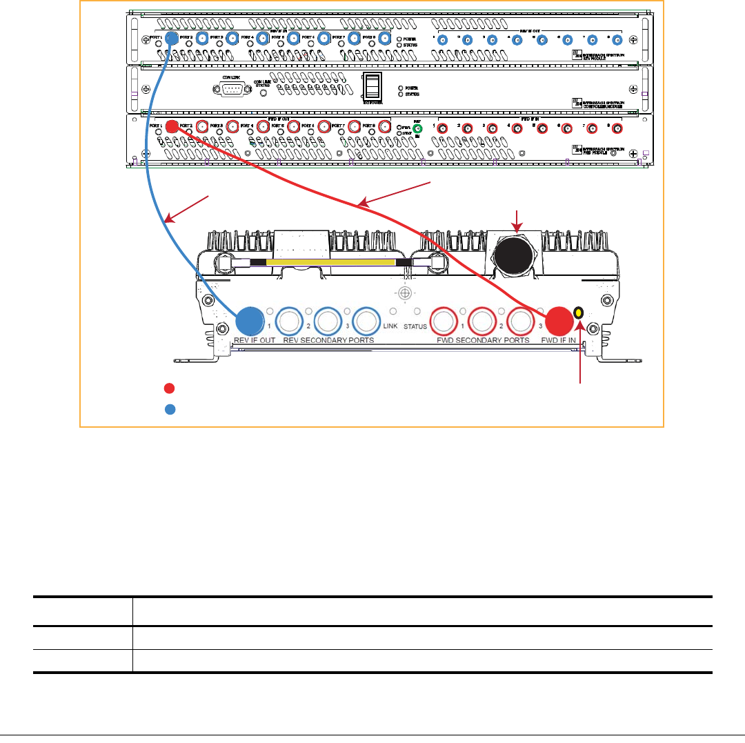
ConnecttheIFEUtotheMRAU
NOTE: TheIFEUshouldbepoweredupbeforestartingthisprocedure;seetheInterReachSpectrumExpansionModuleGroup
InstallationGuide(TECP‐77‐167).
4FollowtheserulesfortheCATVcableswhenconnectingtheIFEUtotheMRAU:
•TheFWDandREVcablesshouldbeclosetothesamelength.
•TheFWDandREVcablesshouldbethesamecabletype(bothRG6orbothRG11).
•ApairofCATVcablesconnectseachMRAUtotheIFEU.TheIFEUREVModuleIFINportandtheIFEU
FWDModuleIFOUTportmustmatch.Forexample,ifIFEUREVModuleIFINPort3isused,useIFEU
FWDModuleIFOUTPort3.
•Referto“75‐OhmCATVCableRequirementsandSpecifications”onpage 20forinformationonmaximum
RG‐6orRG‐11CATVcablelengths.
5TestthecableterminationforeachCATVcablebeforeinstallingit.
Omni Antenna
False Ceiling
SRAU N1
REV IF OUT REV SECONDARY PORTS
1 2 3
FWD SECONDARY PORTS
1 2 3
FWD IF IN
LINK STATUS
LINK STATUS
SECONDARY
REV
SECONDARY
FWD
MRAU N1
Coaxial cable
Coaxial cable
Page12 InterReachSpectrumRemoteAccessUnitInstallationGuide‐PreliminaryNotforDistribution
©2014 TEConnectivityLtd. TECP‐77‐222Issue2 • 300001759666RevB•March2014
6ConnectFconnectorCATVcablesontheIFEUandMRAU,intheordergivenbelow.
IftheLEDsdonotperformasdescribedinthisprocedure,referto“MRAULEDs”onpage 6.
aConnectaCATVcablefromoneoftheIFEUFWDModuleIFOUTconnectors(1‐8)totheMRAUFWDIF
INconnector.
bConfirmthattheMRAUFWDIFINLEDisyellow,whichindicatesacorrectphysicalconnection.
cConnectaCATVcablefromtheIFEUREVModuleIFINconnector(1‐8)totheMRAUREVIFOUT
connector,makingsurethatyoupairtheportusedtothesameportnumberselectedinStep6a.
Iftheconnectioniscorrect,theMRAUpowersupandtheMRAUFWDIFINLEDturnsgreen.
NOTE: TorqueappliedtotheFconnectorCATVcablesshouldbe7±5%in‐lbs.
ConnecttheMRAUtoSRAUs
CAUTION! Topreventinterference,donotinstallan850/1900MRAUantennanearan800/900SRAU.The850MHzbandmust
be20feetawayfromthe800/1900SRAU’spassiveantenna.
7Useoneofthefollowing6’and20’CATVRG6jumpers,availableforpurchasefromTEConnectivity,to
connectanMRAUtoSRAUs.
8TestthecableterminationforeachCATVcablebeforeinstallingit.
TEPartNumber Description Note
300469‐06’RG‐6Cable;FMaletoFMale CATVcablethatconnectstheMRAUtoSRAUs.TwocablesrequiredperSRAU.
300469‐120’RG‐6Cable;FMaletoFMale CATVcablethatconnectstheMRAUtoSRAUs.TwocablesrequiredperSRAU.
Step 6a
IFEU
REV IF OUT REV SECONDARY PORTS
1 2 3
FWD SECONDARY PORTS
1 2 3
FWD IF IN
LINK STATUS
MRAU
To an antenna
Step 6c
KEY:
IFEU FWD Module IF OUT connector to MRAU FWD IF IN connector
IFEU REV Module IF IN connector to MRAU REV IF OUT connector
Step 6b
InterReachSpectrumRemoteAccessUnitInstallationGuide‐PreliminaryNotforDistribution Page13
TECP‐77‐222Issue2 • 300001759666RevB•March2014 ©2014 TEConnectivityLtd.
9ConnectFconnectorCATVcablesfromtheMRAUtoanSRAU,intheordergivenbelow.IftheLEDsdonot
performasdescribedinthisprocedure,referto“SRAULEDs”onpage 8.
aConnectaCATVcablefromanMRAUFWDSECONDARYPORT(1,2,or3)FconnectortotheSRAU
SECONDARYFWDFconnector.
bConfirmthattheSRAUSECONDARYFWDLEDisyellow,whichindicatesacorrectphysicalconnection.
cConnectaCATVcablefromanMRAUREVSECONDARYPORT(1,2,or3)FconnectortotheSRAU
SECONDARYREVFconnector,matchingthesameportnumberselectedinStep9a.Thatis,ifinStep9a
youconnectedanFconnectortotheMRAUFWDSECONDARYPORT1,thepairedCATVcablemust
connecttotheMRAUREVSECONDARYPORT1.
Iftheconnectioniscorrect,theSRAUpowersupandtheSRAUSECONDARYFWDLEDturnsgreen.
NOTE: TorqueappliedtotheFconnectorCATVcablesshouldbe7±5%in‐lbs.
MRAU
REV IF OUT REV SECONDARY PORTS
1 2 3
FWD SECONDARY PORTS
1 2 3
FWD IF IN
LINK STATUS
KEY:
MRAU FWD Secondary port to SRAU Secondary FWD port
MRAU REV Secondary port to SRAU Secondary REV port
LINK STATUS
SECONDARY
REV
SECONDARY
FWD
SECONDARY
REV
SECONDARY
FWD
LINK STATUS
SRAU
To an antenna
To an antenna
To an IFEU
REV Module
IF IN connector
(1 - 8)
To an IFEU
FWD Module
IF OUT connector
(1 - 8)
Step 9a
Step 9b
Step 9c
Page14 InterReachSpectrumRemoteAccessUnitInstallationGuide‐PreliminaryNotforDistribution
©2014 TEConnectivityLtd. TECP‐77‐222Issue2 • 300001759666RevB•March2014
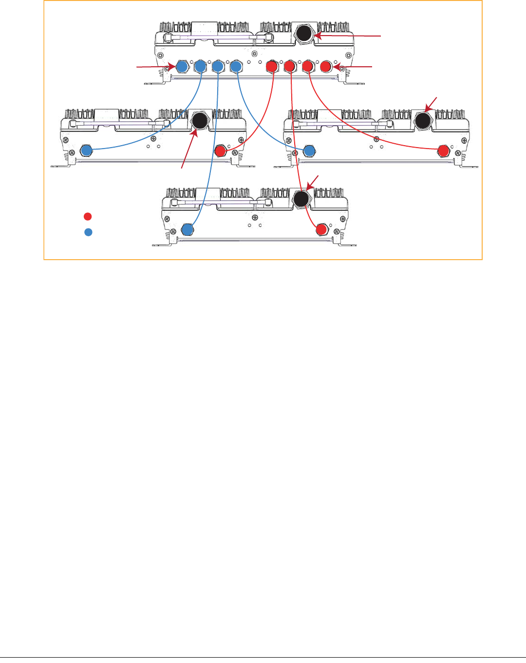
10 RepeatStep 9toinstalluptotwomoreSRAUs,aspersystemdesign.
ConfiguretheMRAUsandSRAUs
RefertotheInterReachSpectrum™ElementManagementSystem7.3UserManual(TECP‐77‐200)forinformation
onhowtoconfiguretheMRAUsandSRAUs.
SPECIFICATIONS
RemoteAccessUnitSpecifications
OperatingTemp ‐25°Cto+50°C
StorageTemperature ‐40°Cto+70°C
Humidity 10%to95%non‐condensing
Dimensions 11.50"Wx3.50"Hx9.00"D
Weight 7.49Pounds
PowerSource +54Vdc(fromIFEU)
SpectrumSystemSpecifications
RFSpecification
SupportedFrequencyBlocks 2perRemoteAntennaUnit;1‐8perHostUnit
Bandwidth 1.5to75MHznon‐contiguous
REV IF OUT REV SECONDARY PORTS
1 2 3
FWD SECONDARY PORTS
1 2 3
FWD IF IN
LINK STATUS
LINK STATUS
SECONDARY
REV
SECONDARY
FWD
LINK STATUS
SECONDARY
REV
SECONDARY
FWD
LINK STATUS
SECONDARY
REV
SECONDARY
FWD
MRAU
SRAU1
SRAU2
SRAU3
To an IFEU FWD Module
IF OUT connector (1 - 8)
To an IFEU REV Module
IF IN connector (1 - 8)
To an antenna
To an antenna
To an antenna
To an antenna
KEY: FWD
REV

InterReachSpectrumRemoteAccessUnitInstallationGuide‐PreliminaryNotforDistribution Page15
TECP‐77‐222Issue2 • 300001759666RevB•March2014 ©2014 TEConnectivityLtd.
PropagationDelay
SystemDelay <12microsecondsperDRUlink
(Forexample,inacascadeof3DRUs,theoverallSystemDelaycouldbe
upto36microseconds.ThisdoesnotincludeFiberDelay,justSystem
Delayalongeachsegmentofthecascade.)
DelayManagementDigital (ManualorAutomatic)
NominalPassbandBandwidthsandGains
FrequencyBandsSupported 850Cellular;800iDEN;900iDEN;1900PCS;2100AWS;2600LTE;700
UpperC/LowerABC
Table3.
RFFrequency
TX RX
850Cell
Bandwidth 869‐894 824‐849
Gain(dB) 40 30
800SMR
Bandwidth 851‐869 806‐824
Gain(dB) 40 30
900SMR
Bandwidth 935‐940 896‐901
Gain(dB) 40 30
1900PCS
Bandwidth 1930‐1995 1850‐191
5
Gain(dB) 40 30
2100AWS
Bandwidth 2110‐2155 1710‐175
5
Gain(dB) 40 30
2600LTE
Bandwidth 2620‐2690 2500‐257
0
Gain(dB) 40 30
700UpperC
Bandwidth 746‐756 776‐786
Gain(dB) 40 30
700LowerABC
Bandwidth 728‐746 698‐716
Gain(dB) 40 30

Page16 InterReachSpectrumRemoteAccessUnitInstallationGuide‐PreliminaryNotforDistribution
©2014 TEConnectivityLtd. TECP‐77‐222Issue2 • 300001759666RevB•March2014
Low/Medium
PowerLevel
700‐900MHz
Typical
Low/Medium
PowerLevel
1900‐2600MHz
Typical
High
PowerLevel
1900‐2600MHz
Typical3
TX RX TX RX TX RX
Averagegainwith180mCATV
at25°C(77°F)(dB)
401/43230 401/43230 48 30
Ripplewith180mCATV(dB) 2.5 3.0 3.5 4.0 3.5 4.0
OutputIP3(dBm) 38 38 43
InputIP3(dBm) ‐8‐8‐8
Output1dBCompressionPoint(dBm) 26 26 31
NoiseFigure1HU‐1EMG‐8RAUs(dB) 17 17 17
NoiseFigure1HU‐4EMG‐32RAUs(dB) 23 23 23
1LowPowerisdefinedhereasaStandardMRAUusedwith
StandardSRAUs;seeTable 4onpage 17.
2MediumPowerisdefinedhereasaHighPowerMRAUused
withStandardSRAUs;seeTable 5onpage 18.
3HighPowerisusedtodefineaHighPowerMRAUusedwith
HighPowerSRAUs;seeTable 6onpage 19.
InterReachSpectrumRemoteAccessUnitInstallationGuide‐PreliminaryNotforDistribution Page17
TECP‐77‐222Issue2 • 300001759666RevB•March2014 ©2014 TEConnectivityLtd.
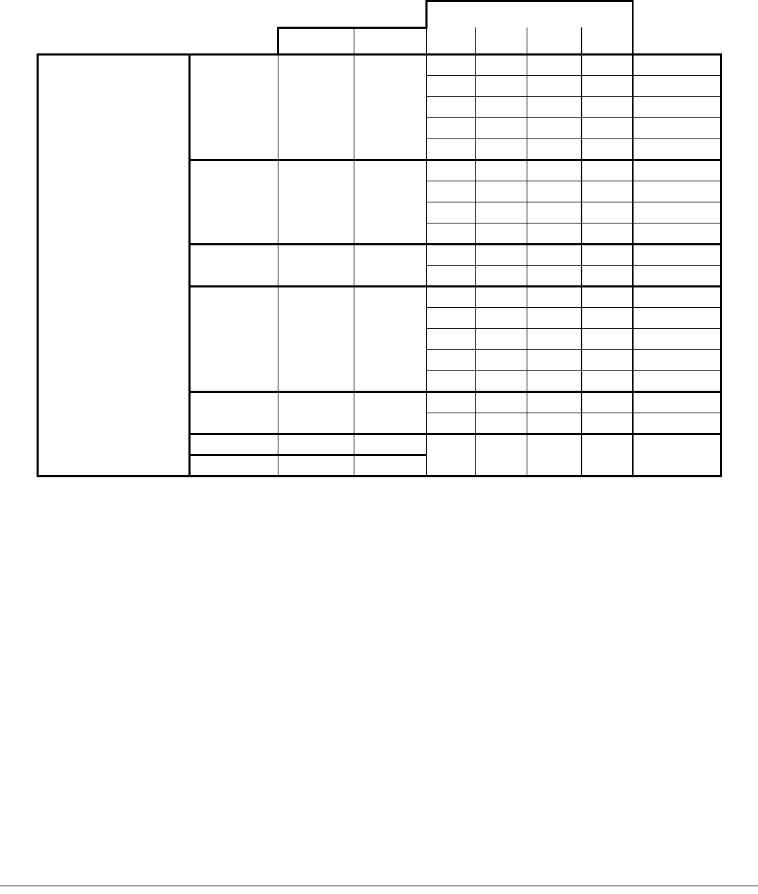
CompositePowerOutofRAU
Table4. LowPowerLevel:StandardMRAUwithSRAUs
PowerperCarrier(dBm)perBand
RFFrequency NumberofRFCarriers
TX RX 1P‐out 2P‐out 4P‐Out 8P‐out
StandardMRAUs:
850Cell 869‐894 824‐849
26.0 20.0 14.0 9.0 GSM
•SPT‐M1‐8519‐1 23.0 17.5 12.0 8.0 EDGE
•SPT‐M1‐AWS19‐11 15.0 12.0 9.0 6.0 CDMA
15.0 12.0 9.0 6.0 WCDMA
StandardSRAUs 15.0 12.0 9.0 6.0 LTE
•SPT‐S1‐8090‐1
800SMR 851‐869 806‐824
17.5 14.0 10.0 6.5 iDEN
•SPT‐S1‐7070‐1‐MIMO 26.0 19.5 13.5 8.5 APCO25C4FM
•SPT‐S1‐80AWS‐1 15.0 12.0 9.0 6.0 CDMA
•SPT‐S2‐70AWS‐1‐SISO 15.0 12.0 9.0 6.0 LTE
•SPT‐S2‐70AWS‐22‐SISO 900SMR 935‐940 896‐901 17.5 14.0 10.0 6.5 iDEN
•SPT‐S1‐AWS19‐12 26.0 20.0 13.5 9.0 APCO25C4FM
•SPT‐S1‐2121‐1‐MIMO
1900PCS 1930‐1995 1850‐1915
26.0 20.0 14.0 9.0 GSM
•SPT‐S1‐8019‐22 23.0 17.5 12.0 8.0 EDGE
•SPT‐S1‐8519‐22 15.0 12.0 9.0 6.0 CDMA
15.0 12.0 9.0 6.0 WCDMA
15.0 12.0 9.0 6.0 LTE
2100AWS 2110‐2155 1710‐1755 15.0 12.0 9.0 6.0 WCDMA
15.0 12.0 9.0 6.0 LTE
700UpperC 746‐756 776‐786 15.0 12.0 9.0 6.0 LTE
700LowerABC 728‐746 698‐716

Page18 InterReachSpectrumRemoteAccessUnitInstallationGuide‐PreliminaryNotforDistribution
©2014 TEConnectivityLtd. TECP‐77‐222Issue2 • 300001759666RevB•March2014
1SeepowerpercarrierofHPMRAUfromTable 6onpage 19.
Table5. MediumPowerLevel:HighPowerMRAUs1usedwithStandardSRAUs
PowerperCarrier(dBm)perBand
RFFrequency NumberofRFCarriers
TX RX 1P‐out 2P‐out 4P‐Out 8P‐out
850Cell 869‐894 824‐849
26.0 20.0 14.0 9.0 GSM
23.0 17.5 12.0 8.0 EDGE
18.0 15.0 12.0 9.0 CDMA
18.0 15.0 12.0 9.0 WCDMA
StandardSRAUs 18.0 15.0 12.0 9.0 LTE
•SPT‐S1‐8090‐1
800SMR 851‐869 806‐824
17.5 14.0 10.0 6.5 iDEN
•SPT‐S1‐7070‐1‐MIMO 26.0 19.5 13.5 8.5 APCO25C4FM
•SPT‐S1‐80AWS‐1 18.0 15.0 12.0 9.0 CDMA
•SPT‐S2‐70AWS‐1‐SISO 18.0 15.0 12.0 9.0 LTE
•SPT‐S2‐70AWS‐22‐SISO 900SMR 935‐940 896‐901 17.5 14.0 10.0 6.5 iDEN
•SPT‐S1‐AWS19‐12 26.0 19.5 13.5 8.5 APCO25C4FM
•SPT‐S1‐2121‐1‐MIMO
1900PCS 1930‐1995 1850‐1915
26.0 20.0 14.0 9.0 GSM
•SPT‐S1‐8019‐22 23.0 17.5 12.0 8.0 EDGE
•SPT‐S1‐8519‐22 18.0 15.0 12.0 9.0 CDMA
18.0 15.0 12.0 9.0 WCDMA
18.0 15.0 12.0 9.0 LTE
2100AWS 2110‐2155 1710‐1755 18.0 15.0 12.0 9.0 WCDMA
18.0 15.0 12.0 9.0 LTE
700UpperC 746‐756 776‐786 18.0 15.0 12.0 9.0 LTE
700LowerABC 728‐746 698‐716

InterReachSpectrumRemoteAccessUnitInstallationGuide‐PreliminaryNotforDistribution Page19
TECP‐77‐222Issue2 • 300001759666RevB•March2014 ©2014 TEConnectivityLtd.
NOTE: ModelsSPT‐M3‐8019‐31‐HPandSPT‐S3‐8019‐22‐HP‐IndustryCanadaMeanOutputPoweris24.33dBm(800SMR)
and26.83dBm(1900PCS).
Table6. HighPowerLevel:HighPowerMRAUwithHighPowerSRAUs
PowerperCarrier(dBm)perBand
RFFrequency NumberofRFCarriers
TX RX 1P‐out 2P‐out 4P‐Out 8P‐out
850Cell 869‐894 824‐849
26.0 20.0 14.0 9.0 GSM
HighPowerMRAU 23.0 17.5 12.0 8.0 EDGE
•SPT‐M3‐8519‐11‐HP 18.0 15.0 12.0 9.0 CDMA
•SPT‐M3‐8019‐31‐HP 18.0 15.0 12.0 9.0 WCDMA
18.0 15.0 12.0 9.0 LTE
HighPowerSRAUs
800SMR 851‐869 806‐824
17.5 14.0 10.0 6.5 iDEN
•SPT‐S3‐70AWS‐11‐HP 26.0 19.5 13.5 8.5 APCO25C4FM
•SPT‐S3‐70AWS‐22‐HP 18.0 15.0 12.0 9.0 CDMA
•SPT‐S3‐8519‐22‐HP 18.0 15.0 12.0 9.0 LTE
•SPT‐S3‐2626‐12‐HP 900SMR 935‐940 896‐901 17.5 14.0 10.0 6.5 iDEN
•SPT‐S3‐8019‐22‐HP 26.0 19.5 13.5 8.5 APCO25C4FM
1900PCS 1930‐1995 1850‐1915
26.0 23.0 19.0 14.0 GSM
26.0 22.5 17.0 13.0 EDGE
23.0 20.0 17.0 14.0 CDMA
23.0 20.0 17.0 14.0 WCDMA
23.0 20.0 17.0 14.0 LTE
2100AWS 2110‐2155 1710‐1755 23.0 20.0 17.0 14.0 WCDMA
23.0 20.0 17.0 14.0 LTE
2600LTE 2620‐2690 2500‐2570 23.0 20.0 17.0 14.0 WCDMA
23.0 20.0 17.0 14.0 LTE
700UpperC 746‐756 776‐786 18.0 15.0 12.0 9.0 LTE
700LowerABC 728‐746 698‐716
Page20 InterReachSpectrumRemoteAccessUnitInstallationGuide‐PreliminaryNotforDistribution
©2014 TEConnectivityLtd. TECP‐77‐222Issue2 • 300001759666RevB•March2014
75‐OHMCATVCABLEREQUIREMENTSANDSPECIFICATIONS
The75‐OhmCATVCable:
•connectstheIFEUtoMRAU(s)andtheMRAU(s)totheSRAU(s)
•transmits(FWD)multibandandreceives(REV)IFsignals
•deliversDCelectricalpowertotheRAUs.TheSpectrumIFEUDCvoltageoutputis+54Vdcnominal.Ifthe
IFEUreachesitscurrentlimit,acurrent‐limitingcircuitprotectsit.
•carriesconfigurationandstatusinformation
•uses75type‐Fconnectorswithcaptivecenterpins.
CATVCableRequirements
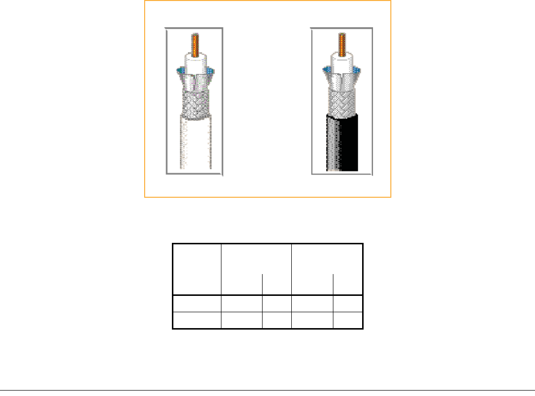
BeldenCATVcableorequivalentisrequired(seeFigure 2).
•FortheRG‐6cable,useaBelden1695ACoax.
•FortheRG‐11cable,useaBelden7732ACoax.
NOTE: TEConnectivityrequiressolidcoppercenterconductorCATVcableforproperDCvoltagetotheRAUandmaximum
distances.
Figure2.Belden1695Aand7732ACoaxCables
•UseRG‐6orRG‐11CATVcablebetweentheIFEUandMRAU,thetypicallengthsofwhicharelistedbelow.
CableType
Minimum
Length
Maximum
Length
Meters Feet Meters Feet
RG‐6 0 0 125 410
RG‐11 0 0 180 590
RG-11
Belden 1695A Coax
RG-6
Belden 7732A Coax

InterReachSpectrumRemoteAccessUnitInstallationGuide‐PreliminaryNotforDistribution Page21
TECP‐77‐222Issue2 • 300001759666RevB•March2014 ©2014 TEConnectivityLtd.
•UseonlyRG‐6CATVcablebetweentheMRAUandSRAU,thelengthsofwhicharelistedbelow.
Belden1695ACoaxSpecifications
Description
RG‐6/Utype,18AWGsolid0.040‐inchbarecopperconductor,plenum,foamFluorinatedEthylenePropylene(FEP)
insulation,Duofoil®+tinnedcopperbraidshield(95%coverage),Flamarrest®jacket.
OverallPhysicalCharacteristics
Conductor OneCoax
18AWG
Solidstranding
BareCopper(BC)conductormaterial
0.040‐inchdiameter
Insulation Teflon®
FoamFluorinatedEthylenePropylene(FFEP)
0.170‐inchdiameter
OuterShieldLayer1Duofoil
®
Tape
AluminumFoil‐PolyesterTape‐AluminumFoil
100%coverage
OuterShieldLayer2Braid
TinnedCopper(TC)
95%coverage
OuterJacket Flamarrest®
LowSmokePolyvinylChloride(LSPVC)
OverallCabling 0.234‐inchoverallnominaldiameter
RG‐6Cable Meters Feet
Typical 26.56
800/900iDENto850CELL 619.68
800AWSto850CELL 619.68

Page22 InterReachSpectrumRemoteAccessUnitInstallationGuide‐PreliminaryNotforDistribution
©2014 TEConnectivityLtd. TECP‐77‐222Issue2 • 300001759666RevB•March2014
OverallNominalElectricalCharacteristics
CharacteristicImpedance 75.000
Inductance 0.103H/ft.
CapacitanceConductortoShield 16.100(pF/ft.)
VelocityofPropagation 82(%)
Delay 1.240(ns/ft.)
ConductorDCResistance 6.400@20°C(/1000ft.)
OuterShieldDCResistance 2.800@20°C(/1000ft.)
Attenuation
Freq.(MHz) Attenuation(dB/100ft.)
1.000 0.240
3.580 0.450
5.000 0.550
7.000 0.650
10.000 0.750
67.500 1.740
71.500 1.780
88.500 1.940
100.000 2.100
135.000 2.400
143.000 2.500
180.000 2.800
270.000 3.400
360.000 4.000
540.000 5.200
720.000 6.100
750.000 6.200
1000.000 7.300
1500.000 9.200
2000.000 10.900
2250.000 11.600
3000.000 13.700

InterReachSpectrumRemoteAccessUnitInstallationGuide‐PreliminaryNotforDistribution Page23
TECP‐77‐222Issue2 • 300001759666RevB•March2014 ©2014 TEConnectivityLtd.
Belden7732ACoaxSpecifications
Description
RG‐11/Utype,14AWGsolid0.064‐inchbarecopperconductor,plenum,foamFEPinsulation,Duofoil®+tinned
copperbraidshield(95%coverage),fluorocopolymerjacket.
OverallPhysicalCharacteristics
Conductor OneCoax
18AWG
Solidstranding
BareCopper(BC)conductormaterial
0.064‐inchdiameter
Insulation Teflon®
FoamFluorinatedEthylenePropylene(FFEP)
0.274‐inchdiameter
OuterShieldLayer1Duofoil
®
Tape
AluminumFoil‐PolyesterTape‐AluminumFoil
100%coverage
OuterShieldLayer2Braid
TinnedCopper(TC)
95%coverage
OuterJacket Fluorocopolymer(PVDF)
OverallCabling 0.348‐inchoverallnominaldiameter

Page24 InterReachSpectrumRemoteAccessUnitInstallationGuide‐PreliminaryNotforDistribution
©2014 TEConnectivityLtd. TECP‐77‐222Issue2 • 300001759666RevB•March2014
OverallNominalElectricalCharacteristics
CharacteristicImpedance 75.000
Inductance 0.091H/ft.
CapacitanceConductortoShield 16.300(pF/ft.)
VelocityofPropagation 83(%)
Delay 1.220(ns/ft.)
ConductorDCResistance 2.500@20°C(/1000ft.)
OuterShieldDCResistance 1.600@20°C(/1000ft.)
Attenuation
Freq.(MHz) Attenuation(dB/100ft.)
1.000 0.150
3.580 0.260
5.000 0.300
7.000 0.340
10.000 0.400
67.500 1.200
71.500 1.240
88.500 1.400
100.000 1.500
135.000 1.780
143.000 1.840
180.000 2.090
270.000 2.600
360.000 3.100
540.000 3.890
720.000 4.570
750.000 4.680
1000.000 5.500
1500.000 6.910
2000.000 8.130
2250.000 9.200
3000.000 10.200

InterReachSpectrumRemoteAccessUnitInstallationGuide‐PreliminaryNotforDistribution Page25
TECP‐77‐222Issue2 • 300001759666RevB•March2014 ©2014 TEConnectivityLtd.
OMNIANTENNASPECIFICATIONS
TheOmniAntenna(4214‐0727),showninFigure3,isaroundradomewiththefollowingspecifications:
Figure3.OmniAntenna
NOTE: TwoantennasperRAUisrequiredforMIMOperformance.
CAUTION! Maximumgainantennaallowedis3dBi
Port1Port2Port3
Gain,typical 2dBi@698‐960MHz 2dBi@698‐960MHz 3dBi@1710‐2170MHz
3dBi@1710‐2170MHz 3dBi@1710‐2170MHz 3dBi@2496‐2690MHz
Nominalimpedance 50Ohm
Polarization Vertical
VSWR <2:1
Port‐to‐portisolation >15dBmin,22dBtypical
Powerrating 5Watt
Mechanical
DimensionofAntenna(DxH) 215x72mm
Weight Lessthanorequalto1.65lbs(0.75kg),includingpigtails
Connector N(male)
Cable(pigtail)length 6feet,plenumratedcable
Color White,UVprotectedplasticforoutdooruse
Mountinghardware Screws,anchor,andbutterflynutforceilingtilemount
Environmental
Operatingtemperature ‐40°Cto+65°C
ShippingandHandling ISTAProcedure1A
Ingressprotection IP‐42
Flammability UL94V0(Materials)
Compliance ROHScompliant
Ceiling mount, vertically polarized, omni directional antenna

Page26 InterReachSpectrumRemoteAccessUnitInstallationGuide‐PreliminaryNotforDistribution
©2014 TEConnectivityLtd. TECP‐77‐222Issue2 • 300001759666RevB•March2014
STANDARDSCERTIFICATION
FederalCommunicationsCommission(FCC)
ThisequipmentcomplieswiththeapplicablesectionsofTitle47CFR,Part22(800MHzCellular),Part24(1900MHz‐PCS),
Part90(800/900‐SMR),andPart27(700MHz,2100MHz‐AWS).
Part90SignalBoosters
ThefollowingstatementisapplicabletothefollowingRAUsthataredocumentedinthisinstallationguide:
SPT‐M3‐8019‐31‐HP,SPT‐S1‐8019‐22,SPT‐S1‐8090‐1,SPT‐S1‐80AWS‐1,SPT‐S3‐8019‐22‐HP.
WARNING.ThisisNOTaCONSUMERdevice.ItisdesignatedforinstallationbyFCCLICENSEESandQUALIFIED
INSTALLERS.YouMUSThaveanFCCLICENSEorexpressConsentofanFCCLicenseetooperatethisdevice.Unauthorized
usemayresultinSignificantforfeiturepenalties,includingpenaltiesinexcessof$100,000foreachcontinuingviolation.
IndustryCanada(IC)
ThisequipmentcomplieswiththeapplicablesectionsofRSS‐131‐ZoneEnhancersfortheLandMobileService.Theterm
“IC:”beforetheradiocertificationnumberonlysignifiesthatIndustryCanadaTechnicalSpecificationsweremet.
TheManufacturer'sratedoutputpowerofthisequipmentisforsinglecarrieroperation.Forsituationswhenmultiple
carriersignalsarepresent,theratingwouldhavetobereducedby3.5dB,especiallywheretheoutputsignalisre‐radiated
andcancauseinterferencetoadjacentbandusers.Thispowerreductionistobebymeansofinputpowerorgainreduction
andnotbyanattenuatorattheoutputofthedevice.
NOTE: TheU.S.FederalCommunicationsCommission(FCC)hasdevelopedguidelinesforevaluationofhumanexposureto
RFemissions.TheguidelinesincorporatelimitsforMaximumPermissibleExposure(MPE)forpowerdensityof
transmitteroperatingatfrequenciesbetween300kHzand100GHz.Limitshavebeensetforportable,mobile,and
fixedequipment.TEConnectivityproductsfallinthecategoryoffixedequipment;productsintendedtobe
permanentlysecuredandexposuresareevaluatedfordistancesgreaterthan40cm(15.75”).Portabledevicesfallinto
exposuresoflessthan20cm,whereSARevaluationsareused.
Antennagainisrestrictedto1.5WERP(2.49WEIRP)inordertosatisfyRFexposurecompliancerequirements.
Ifhigherthan1.5WERP,routineMPEevaluationisneeded.Theantennasshouldbeinstalledtoprovideat
least40cmfromallpersonstosatisfyMPErequirementsofFCCPart2,2.1091.
ThisdevicecomplieswithIndustryCanadalicence‐exemptRSSstandard(s).Operationissubjecttothefollowingtwo
conditions:(1)thisdevicemaynotcauseinterference,and(2)thisdevicemustacceptanyinterference,including
interferencethatmaycauseundesiredoperationofthedevice.
LeprésentappareilestconformeauxCNRd’IndustrieCanadaapplicablesauxappareilsradioexemptsdelicence.
L’exploitationestautoriséeauxdeuxconditionssuivantes:(1)l’appareilnedoitpasproduiredebrouillage,et(2)
l’utilisateurdel’appareildoitacceptertoutbrouillageradioélectriquesubi,mêmesilebrouillageestsusceptibled’en
compromettrelefonctionnement.
Thedevicemeetstheexemptionfromtheroutineevaluationlimitsinsection2.5ofRSS102andcompliancewithRSS‐102
RFexposure,userscanobtainCanadianinformationonRFexposureandcompliance.
Ledispositifrencontrel'exemptiondeslimitescourantesd'évaluationdanslasection2.5deRSS102etlaconformitéà
l'expositiondeRSS‐102rf,utilisateurspeutobtenirl'informationcanadiennesurl'expositionetlaconformitéderf.
UL/CUL
Thisequipmentwillbeinstalledinarestrictedaccesslocation.Thisequipmentcomplies,perULandCUL50,Standardfor
EnclosuresforElectricalEquipment.
ThisequipmentcomplieswithULandCUL60950‐1StandardforSafetyforInformationTechnologyEquipment,including
ElectricalBusinessEquipment.
AllInterReachSpectrumRAUsarePlenumratedandsuitableforuseinenvironmentalairspaceinaccordancewithSection
300‐22(C)oftheNationalElectricalCode,andSections2‐128,12‐010(3)and12‐100oftheCanadianElectricalCode,Part
1,CSAC22.1.

InterReachSpectrumRemoteAccessUnitInstallationGuide‐PreliminaryNotforDistribution Page27
TECP‐77‐222Issue2 • 300001759666RevB•March2014 ©2014 TEConnectivityLtd.
ThisequipmentisULPlenumratedunderUL2043.
CAUTION! Modificationsnotexpresslyapprovedbythepartyresponsibleforcompliancecouldvoidtheuser'sauthorityto
operatetheequipment.
ACCESSINGUSERDOCUMENTATIONONTHETECUSTOMERPORTAL
YoucanaccessadditionaluserdocumentationontheTECustomerPortal,asdescribedbelow.
1ClickonthefollowingURLlink:
https://www.te.com/portal/wireless/
(Alternatively,entertheprecedingURLintoyourwebbrowser,andthenpressENTERonyourkeyboard.)
2AccesstotheCustomerPortalrequiresauseraccountandpassword.OntheSignInpage,dooneofthe
following:
•Ifyouhaveanaccount,intheAlreadyRegistered?SignInNowpanel,enteryourEmailandPassword,and
thenclickSignIn.
•Ifyoudon’thaveanaccount,underCreateanAccount,clickRegisterNowandfollowtheprompts.
3OntheWirelessCustomerPortalhomepageintheKnowledgeCenterpanel,clicktheManualsandDataSheets
link.
4OntheManualsandDataSheetspage,dothefollowing:
aIntheDocumentRepositorypanel,scrolltothesectionfortheproductlineofthedocumentthatyouwant
toaccess.
bClickonthetitleofthemanualthatyouwishtoopen.
c(Optional)SavethePDFtoyourcomputer.

Page28 InterReachSpectrumRemoteAccessUnitInstallationGuide‐PreliminaryNotforDistribution
©2014 TEConnectivityLtd. TECP‐77‐222Issue2 • 300001759666RevB•March2014
CONTACTINGTECONNECTIVITY
TelephoneNumbers
Sales
AsiaPacific +65‐6294‐9948
France 0800914032
Germany 01802232923
Italy 0800782374
Spain 900983291
UnitedKingdom 0800960236
USAorCanada 1‐800‐366‐3891
Extension 73000
ConnectivityExtension 73475
WirelessExtension 73476
TechnicalSupport
USAorCanada 1‐800‐530‐9960
Elsewhere +1‐952‐917‐0761
OnlineAccess
CustomerPortal
https://www.te.com/portal/wireless/
TechnicalSupportforWirelessProducts
http://www.te.com/WirelessSupport
www.te.com/wireless