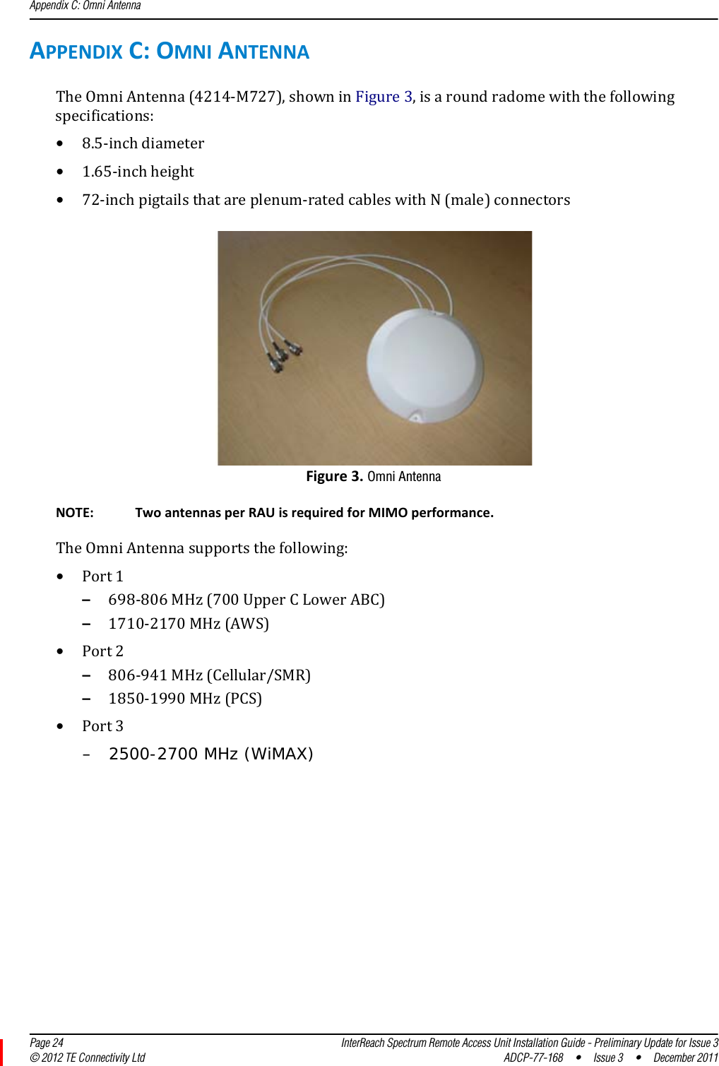
ADC Telecommunications S2983-012 Spectrum 700 Path 1/700 Path 2 MIMO RFIC SRAU User Manual

ADC Telecommunications Inc. Spectrum 700 Path 1/700 Path 2 MIMO RFIC SRAU

User Manual

ADCP-77-168  Issue 3  July 2012D-620731-0-20 Rev CInterReach Spectrum™ Remote Access Unit Installation Guide - Preliminary Update - Issue 3Main Remote Access UnitSecondary Remote Access Unit
Copyright© 2012 TE Connectivity, Inc. All Rights Reserved.Information contained in this document is company private to TE Connectivity Ltd., and shall not be modified, used, copied, reproduced or disclosed in whole or in part without the written consent of TE.Trademark InformationFlexWave, FlexWave Prism, InterReach Spectrum, Universal Radio Head, TE Connectivity, and TE connectivity (logo) are trademarks.All other logos, products and/or company names referred to herein might be trademarks of their respective owners. Disclaimer of LiabilityContents herein are current as of the date of publication. TE reserves the right to change the contents without prior notice. Should the content of printed user documentation shipped with product differ from documentation provided on a product CD (inclusive of the associated Help modules), the printed user documentation supersedes the documentation on the product CD. In no event shall TE be liable for any damages resulting from loss of data, loss of use, or loss of profits, and TE further disclaims any and all liability for indirect, incidental, special, consequential or other similar damages. This disclaimer of liability applies to all products, publications and services during and after the warranty period.Specific Disclaimer for High-Risk ActivitiesThis Product is not specifically designed, manufactured, tested or intended for use in high-risk activities including, without restricting the generality of the foregoing, on-line control of aircraft, air traffic, aircraft navigation or aircraft communications; or in the design, construction, operation or maintenance of any nuclear facility. TE (including its affiliates) and its suppliers specifically disclaim any express or implied warranty of fitness for such purposes or any other purposes.Screenshots in User DocumentationDue to concurrent development of this documentation, artwork, and the InterReach Spectrum Element Management System (EMS), there may be some minor discrepancies between screenshots contained in this documentation and those actually displayed in the InterReach Spectrum EMS. These discrepancies will generally be few and minor and should not affect your understanding of InterReach Spectrum EMS.
InterReach Spectrum Remote Access Unit Installation Guide - Preliminary Update for Issue 3 Page 1ADCP-77-168  •  Issue 3  •  December 2011 ©2012 TE Connectivity Ltd.TABLEOFCONTENTSPreface .................................................................................................................................................................2RevisionHistory...................................................................................................................................................... 2InterReachSpectrumUserDocumentation ........................................................................................................... 3StandardsCertification........................................................................................................................................... 4ProductOverview.................................................................................................................................................5MainRemoteAccessUnits..................................................................................................................................... 6MRAUPorts,Cable,andConnectors ..................................................................................................................................6MRAULEDs .........................................................................................................................................................................7SecondaryRemoteAccessUnits ............................................................................................................................ 8SRAUPorts,Cable,andConnectors....................................................................................................................................8SRAULEDs...........................................................................................................................................................................9RAUNConnectors................................................................................................................................................ 10InstalltheRAUsandAntennas............................................................................................................................11MounttheRAUsandAntennas............................................................................................................................ 11GeneralSafetyPrecautions .................................................................................................................................. 11ConnecttheIFEUtotheMRAU............................................................................................................................12ConnecttheMRAUtoSRAUs ............................................................................................................................... 14ConfiguretheMRAUsandSRAUs......................................................................................................................... 15AppendixA:Specifications..................................................................................................................................16RemoteAccessUnitSpecifications ...................................................................................................................... 16SpectrumSystemSpecifications........................................................................................................................... 16CompositePowerOutofRAU .............................................................................................................................. 18AppendixB:75‐OhmCATVCable........................................................................................................................19CATVCableRequirements.................................................................................................................................... 19Belden1695ACoaxSpecifications ....................................................................................................................... 20Description .......................................................................................................................................................................20OverallPhysicalCharacteristics ........................................................................................................................................20OverallNominalElectricalCharacteristics........................................................................................................................21Belden7732ACoaxSpecifications ....................................................................................................................... 22Description .......................................................................................................................................................................22OverallPhysicalCharacteristics ........................................................................................................................................22OverallNominalElectricalCharacteristics........................................................................................................................23AppendixC:OmniAntenna.................................................................................................................................24AppendixD:ContactingTEConnectivity .............................................................................................................25
Preface  Page 2 InterReach Spectrum Remote Access Unit Installation Guide - Preliminary Update for Issue 3© 2012 TE Connectivity Ltd ADCP-77-168 • Issue 3 • December 2011PREFACEThismanualprovidesinstallationinstructionsforInterReachSpectrum®RemoteAccessUnits(RAUs).Table1liststheRAUsthataresupportedinthisdocument.Table1.SupportedSpectrumRemoteAccessUnitsCatalog Number  DescriptionSPT-M1-8519-1 SPECTRUM, 850-1900 MAIN RAUSPT-M1-AWS19-11 SPECTRUM, 2100AWS Path 1-1900 Path 1 MAIN RAU SPT-S1-2121-1-MIMO SPECTRUM, 2100AWS MIMO SECONDARY RAUSPT-S1-7070-1-MIMO SPECTRUM, 700 MIMO SECONDARY RAU, UpperC-LowerABC SPT-S1-8019-22 SPECTRUM, 800 Path 2-1900 Path 2 SECONDARY RAUSPT-S1-8090-1 SPECTRUM, 800-900 SMR SECONDARY RAUSPT-S1-80AWS-1 SPECTRUM, 800-2100AWS Path 1 SECONDARY RAUSPT-S1-8519-22 SPECTRUM, 850 Path 2-1900 Path 2 SECONDARY RAUSPT-S1-AWS19-12 SPECTRUM, 2100AWS Path 1-1900 Path 2 SECONDARY RAU SPT-S2-70AWS-1-SISO SPECTRUM, 700 SISO-2100AWS Path 1 SEC RAU, UpperC-LowerABCSPT-S2-70AWS-22-SISO SPECTRUM, 700 Path 2 SISO-2100AWS Path 2 SEC RAU, UpperC-LowerABCRevisionHistoryIssue Document Date Technical Updates1September 2010 Original2December 2011 Added “Supported Spectrum Remote Access Units” on page 2, “RAU N Connectors” on page 10, and “Nominal Passband Gains” on page 17. Updated “Appendix D: Contacting TE Connectivity” on page 25.3June 2012 Updated IC standards in “Standards Certification” on page 4; updated “Composite Power Out of RAU” on page 18.
InterReach Spectrum User DocumentationInterReach Spectrum Remote Access Unit Installation Guide - Preliminary Update for Issue 3 Page 3ADCP-77-168  •  Issue 3  •  December 2011 © 2012 TE Connectivity Ltd.InterReachSpectrumUserDocumentationTheInterReachSpectrumuserdocumentationisintendedforsystemadministrators,engineersandinstallersresponsibleforplanning,administering,configuring,andmaintainingTEConnectivityInterReachSpectrumsystems.Table2liststhemanualsthatcorrespondtothisInterReachSpectrumrelease.Table2.InterReachSpectrumUserDocumentationTitle ADCP Number InterReachSpectrumQuickStartGuide ADCP-77-165InterReachSpectrumHostUnitInstallationGuide ADCP-77-166InterReachSpectrumExpansionModuleGroupInstallationGuideADCP-77-167InterReachSpectrumRemoteAccessUnitInstallationGuideADCP-77-168InterReachSpectrumElementManagementSystem7.2UserManualADCP-77-189FlexWavePrismOADMSpliceBoxInstallationGuide ADCP-77-151Twotypesofmessages,identifiedbelow,appearintheInterReachSpectrumuserdocumentation:CAUTION! Cautiontextindicatesoperationsorstepsthatcouldcausepersonalinjury,induceasafetyprobleminamanageddevice,destroyorcorruptinformation,orinterruptorstopservices.NOTE: Notetextcontainsinformationaboutspecialcircumstances.
Preface  Page 4 InterReach Spectrum Remote Access Unit Installation Guide - Preliminary Update for Issue 3© 2012 TE Connectivity Ltd ADCP-77-168 • Issue 3 • December 2011StandardsCertificationFCC:ThisequipmentcomplieswiththeapplicablesectionsofTitle47CFR,Part22(800MHzCellular),Part24(1900MHz‐PCS),Part90(800/900‐SMR),andPart27(700MHz,2100MHz‐AWS).IC:ThisequipmentcomplieswiththeapplicablesectionsofRSS‐131(800/900–SMR),RSS‐132(800‐Cellular),andRSS‐133(1900–PCS).Theterm“IC:”beforetheradiocertificationnumberonlysignifiesthatIndustryCanadaTechnicalSpecificationsweremet.TheManufacturer'sratedoutputpowerofthisequipmentisforsinglecarrieroperation.Forsituationswhenmultiplecarriersignalsarepresent,theratingwouldhavetobereducedby3.5dB,especiallywheretheoutputsignalisre‐radiatedandcancauseinterferencetoadjacentbandusers.Thispowerreductionistobebymeansofinputpowerorgainreductionandnotbyanattenuatorattheoutputofthedevice.NOTE: TheU.S.FederalCommunicationsCommission(FCC)hasdevelopedguidelinesforevaluationofhumanexposuretoRFemissions.TheguidelinesincorporatelimitsforMaximumPermissibleExposure(MPE)forpowerdensityoftransmitteroperatingatfrequenciesbetween300kHzand100GHz.Limitshavebeensetforportable,mobile,andfixedequipment.TEConnectivityproductsfallinthecategoryoffixedequipment;productsintendedtobepermanentlysecuredandexposuresareevaluatedfordistancesgreaterthan40cm(15.75”).Portabledevicesfallintoexposuresoflessthan20cm,whereSARevaluationsareused.Antennagainisrestrictedto1.5WERP(2.49WEIRP)inordertosatisfyRFexposurecompliancerequirements.Ifhigherthan1.5WERP,routineMPEevaluationisneeded.Theantennasshouldbeinstalledtoprovideatleast40cmfromallpersonstosatisfyMPErequirementsofFCCPart2,2.1091.UL/CUL:Thiswillbeinstalledinarestrictedaccesslocation.Thisequipmentcomplies,perULandCUL50,StandardforEnclosuresforElectricalEquipment.UL/CUL:ThisequipmentcomplieswithULandCUL60950‐1StandardforSafetyforInformationTechnologyEquipment,includingElectricalBusinessEquipment.UL/CUL:AllInterReachSpectrumRAUsarePlenumratedandsuitableforuseinenvironmentalairspaceinaccordancewithSection300‐22(C)oftheNationalElectricalCode,andSections2‐128,12‐010(3)and12‐100oftheCanadianElectricalCode,Part1,CSAC22.1.UL:ThisequipmentisULPlenumratedunderUL2043.CAUTION! Modificationsnotexpresslyapprovedbythepartyresponsibleforcompliancecouldvoidtheuser'sauthoritytooperatetheequipment.
Standards CertificationInterReach Spectrum Remote Access Unit Installation Guide - Preliminary Update for Issue 3 Page 5ADCP-77-168  •  Issue 3  •  December 2011 © 2012 TE Connectivity Ltd.PRODUCTOVERVIEWInterReachSpectrumsupportsuptoeightfrequencybandsinasinglesystem.Eachantennalocationsupportsthosebandsinmodular,grouppairings.EachlocationincludesaMainRemoteAccessUnit(MRAU),whichcanpoweruptothreeadditionalSecondaryRemoteAccessUnits(SRAUs).AnMRAUsupportstwofrequencybands,andeachSRAUcansupportuptotwofrequencybands,foratotalofuptoeightfrequencybands.MRAUsandSRAUsaregroupedlogically,basedoncommonserviceprovidergroupingsandinclude,asanexample:•850/1900•700/700MIMO•800/900SMR•1900/AWS.Toaddmorefrequencybands,youconnectanSRAUtotheexistingMRAU.Figure1illustrateshowRFandIFsignalsaresentbetweenSpectrumunitsandmodules.Omni AntennaHostPower SupplyIF Expansion UnitDART Remote UnitExpansion Module GroupSecondary Remote Access UnitMain Remote Access UnitIFRFRFIFReverse (REV)Forward (FWD)Key to Signal PathRFIFFigure1.REV and FWD Signals for the RAUNOTE: ThisbookreferstotheOmniAntenna(4214‐M727),whichistheantennathatTEConnectivityrecommends.Otherantennasmaybeused.ForfurtherinformationontheOmniAntenna,see“AppendixC:OmniAntenna”onpage24.
Product Overview  Page 6 InterReach Spectrum Remote Access Unit Installation Guide - Preliminary Update for Issue 3© 2012 TE Connectivity Ltd ADCP-77-168 • Issue 3 • December 2011MainRemoteAccessUnitsTheMainRemoteAccessUnit(MRAU)receivesFWDIFsignalsfromanIFExpansionUnit(IFEU),whichispartoftheSpectrumExpansionModuleGroup,using75CATVcable.TheMRAUconvertstheIFsignalstoRFandsendsthemtoapassiveRFantennausing50coaxialcable.TheMRAUalsoreceivesconfigurationinformationandpowerfromandsendsitsstatusinformationtotheIFEU.TheMRAUreceivesREVRFsignalsfromapassiveRFantennausing50coaxialcable.ItconvertsthesignalstoIFandsendsthemtotheIFEUusing75CATVcable.MRAUPorts,Cable,andConnectorsREV IF OUT REV  SECONDARY  PORTS   1                 2                 3FWD  SECONDARY  PORTS   1                 2                 3FWD IF INLINK STATUS1 236 54Ref # Component Device Function1RF SubMiniature version A (SMA) cable (1)50 RF SMA-to-SMA cable Connects two RF bands together when there is only one N-type connector on the RAU.For cases when there is an N-type connector for each RF band (700MIMO or PCS/AWS), there will not be an SMA cable.2Antenna port(s) 50 N-type connector Connects to an antenna. See Table 3 on page 10.3FWD IF IN connector F connector port Connects to the IFEU FWD Module IF OUT connector via CATV cable.4FWD SECONDARY PORTS (1 - 3) F connector ports Connect to a SRAU SECONDARY FWD connector via CATV cable.5REV SECONDARY PORTS (1 - 3) F connector ports Connect to a SRAU SECONDARY REV connector via CATV cable.8REV IF OUT connector F connector port Connects to the IFEU REV Module IF IN connector via CATV cable.(1) The AWS/PCS MRAUs does NOT have an RF SMA cable, and has two Antenna ports.
Main Remote Access UnitsInterReach Spectrum Remote Access Unit Installation Guide - Preliminary Update for Issue 3 Page 7ADCP-77-168  •  Issue 3  •  December 2011 © 2012 TE Connectivity Ltd.MRAULEDsREV IF OUT REV  SECONDARY  PORTS   1                 2                 3FWD  SECONDARY  PORTS   1                 2                 3FWD IF INLINK STATUS41 52 3Ref # LED LED Color Description1FWD SECONDARY PORT (1 - 3)2LINK3STATUS4REV SECONDARY PORT(1 - 3)5FWD IF IN• Green • Downstream unit correctly connected; unit has no alarms or a Minor alarm is active.• Blinking Green • SRAU or band is set out-of-service.• Yellow • FWD cable connected to SRAU, no REV cable connected.• Blinking Yellow • FWD and REV cables are not connected to the same port number (incorrectly paired).• Red • Major alarm in downstream unit, fault lockout, or SRAU disconnected.• Off • No SRAU previously connected.•Green •MRAU receiving communications from the IFEU.• Red • MRAU has not received communications from the IFEU for more than 90 seconds.• Off • During initial power up, MRAU is powering up and waiting for IFEU communications.• Green • Unit has no alarms or a Minor alarm is active.• Blinking Green • Unit or band is set out-of-service.• Red • Major alarm detected.• Green • Downstream unit correctly connected, unit has no alarms or minor alarm• Blinking Green • SRAU or band is set out-of-service.• Blinking Yellow • FWD and REV cables are not connected to the same port number (incorrectly paired).• Red • Major alarm in downstream unit, fault lockout, or SRAU disconnected.• Off • No SRAU previously connected.• Green • MRAU is powered on correctly.•Yellow orBlinking Yellow• There is an IFEU FWD connection, but there is no IFEU REV connection or the IFEU REV connection is paired incorrectly.• Off • Cable is not connected to the IFEU FWD port.
Product Overview  Page 8 InterReach Spectrum Remote Access Unit Installation Guide - Preliminary Update for Issue 3© 2012 TE Connectivity Ltd ADCP-77-168 • Issue 3 • December 2011SecondaryRemoteAccessUnitsASecondaryRemoteAccessUnit(SRAU)receivesFWDIFsignalsfromtheMRAU,using75CATVcable.TheSRAUconvertstheIFsignalstoRFandsendsthemtoapassiveRFantennausing50coaxialcable.TheSRAU,throughtheMRAU,alsoreceivesconfigurationinformationandpowerfromandsendsitsstatusinformationtotheIFEU.TheSRAUreceivesREVRFsignalsfromapassiveRFantennausing50coaxialcable.ItconvertsthesignalstoIFandsendsthemtotheMRAUusing75CATVcable.SRAUPorts,Cable,andConnectors1 4LINK STATUSSECONDARYREVSECONDARYFWD23Ref #Component Device Function1SECONDARY REV connector F connector port Connects to one of the MRAU REV SECONDARY ports (1 - 3) via CATV cable.2RF SMA cable (1) 50 RF SMA-to-SMA cableConnects two RF bands together when there is only one N-type connector on the RAU.For cases when there is an N-type connector for each RF band (700MIMO or PCS/AWS), there will not be an SMA cable.3Antenna port(s) 50 N-type connector Connects to an antenna. See Table 3 on page 10.4SECONDARY FWD connector F connector port Connects to one of the MRAU FWD SECONDARY ports (1 - 3) via CATV cable.(1) The 700 MIMO SRAUs does NOT have an RF SMA cable, and has two Antenna ports.
Secondary Remote Access UnitsInterReach Spectrum Remote Access Unit Installation Guide - Preliminary Update for Issue 3 Page 9ADCP-77-168  •  Issue 3  •  December 2011 © 2012 TE Connectivity Ltd.SRAULEDsLINK STATUSSECONDARYREVSECONDARYFWD21 3Ref # LED LED Color Description1 LINK2STATUS3SECONDARY FWD•Green •SRAU receiving communications from the IFEU.• Red • SRAU has not received communications from the IFEU for more than 90 seconds.• Off • During initial power up, SRAU is powering up and waiting for IFEU communications.• Green • Unit has no alarms or a Minor alarm is active.•Blinking Green • Unit or band is set out-of-service.• Red • Major alarm detected.• Green • SRAU is powered on correctly.•Yellow orBlinking Yellow• There is an MRAU FWD connection, but there is no MRAU REV connection or the MRAU REV connection is paired incorrectly.• Off • Cable is not connected to the MRAU FWD port.
Product Overview  Page 10 InterReach Spectrum Remote Access Unit Installation Guide - Preliminary Update for Issue 3© 2012 TE Connectivity Ltd ADCP-77-168 • Issue 3 • December 2011RAUNConnectorsEachRAUalsohasoneortwo50‐N‐typeconnectorsthatconnecttoapassiveantenna.Table3liststhenumberofN‐typeconnectorsavailableoneachRAUmodel.Table3.NumberofNConnectorsonRAUsCatalog Number  Description Number of RFN Connectors*SPT-M1-8519-1 SPECTRUM, 850-1900 MAIN RAU 1SPT-M1-AWS19-11 SPECTRUM, 2100AWS Path 1-1900 Path 1 MAIN RAU  2SPT-S1-2121-1-MIMO SPECTRUM, 2100AWS MIMO SECONDARY RAU 2SPT-S1-7070-1-MIMO SPECTRUM, 700 MIMO SECONDARY RAU, UpperC-LowerABC  2SPT-S1-8019-22 SPECTRUM, 800 Path 2-1900 Path 2 SECONDARY RAU 1SPT-S1-8090-1 SPECTRUM, 800-900 SMR SECONDARY RAU 1SPT-S1-80AWS-1 SPECTRUM, 800-2100AWS Path 1 SECONDARY RAU 1SPT-S1-8519-22 SPECTRUM, 850 Path 2-1900 Path 2 SECONDARY RAU 1SPT-S1-AWS19-12 SPECTRUM, 2100AWS Path 1-1900 Path 2 SECONDARY RAU  2SPT-S2-70AWS-1-SISO SPECTRUM, 700 SISO-2100AWS Path 1 SEC RAU, UpperC-LowerABC 1SPT-S2-70AWS-22-SISO SPECTRUM, 700 Path 2 SISO-2100AWS Path 2 SEC RAU, UpperC-LowerABC 1* There are two bands per RAU, which results in two N connectors. When there is one N connector, the two bands are combined internally and both bands use the single N connector.
Mount the RAUs and AntennasInterReach Spectrum Remote Access Unit Installation Guide - Preliminary Update for Issue 3 Page 11ADCP-77-168  •  Issue 3  •  December 2011 © 2012 TE Connectivity Ltd.INSTALLTHERAUSANDANTENNASFollowthestepsintheorderprovidedtoinstalltheRAUsandantennas.MounttheRAUsandAntennasGeneralSafetyPrecautionsCAUTION! Wetconditionsincreasethepotentialforreceivinganelectricalshockwheninstallingorusingelectricallypoweredequipment.Topreventelectricalshock,neverinstalloruseelectricalequipmentinawetlocationorduringalightningstorm.CAUTION! ThissystemisaRFTransmitterandcontinuouslyemitsRFenergy.Maintainaminimum8‐inch(20cm)clearancefromtheantennawhilethesystemisoperating.Wheneverpossible,shutdowntheRANbeforeservicingtheantenna.NOTE: RAUsaresuitableforuseinenvironmentalairspaceinaccordancewithSection300‐22(c)oftheNationalElectricalCode,andSections2‐128,12‐010(3)and12‐100oftheCanadianElectricalCode,Part1,CSAC22.1.CAUTION! InstallRAUsinindoorlocationsonly.DonotconnectanantennainstalledinanoutdoorlocationtoaRAU,unlessitisinanapprovedAOCweatherproofNEMA4housing.CAUTION! AttachallRAUssecurelytoastationaryobject(thatis,awall,pole,orceilingbrackets).TomountaRAUsecurelytoawall,ceilingbracket,orpole,use#6diameterfastenersinthefourslottedmountingholes.CAUTION! Dothefollowingtomaintainproperventilation:•Keepatleast76mm(3‐inch)clearancearoundtheRAU.•DonotstackRAUsontopofeachother.•AlwaysmounttheRAUwiththesolidface(containingthemountingholes)againstthemountingsurface.NOTE: YoucanplacetheRAU,withoutitsfasteninghardware,onaflatsurface,suchasashelf,desk,cabinet,oranyotherhorizontalsurfacethatallowsstableplacement,withthemountingbasefacingdowntothemountingsurface.CAUTION! IfinstallingtheRAUonaflatsurface,thesurfacemustbeabletoholdaminimum7‐poundloadsecurely.Dothefollowing,intheorderpresented,tomounttheRAUsandantennas:1MountallMRAUandSRAUsinthelocationsmarkedonthefloorplans.2Installthepassiveantennasaccordingtothemanufacturer’sinstallationinstructions.NOTE: Itiscommonpracticetoinstallpassiveantennasbelowtheceiling.Ifyouinstallapassiveantennaabovetheceiling,whenestimatingtheantennacoveragearea,accountforadditionallossduetotheceilingmaterial.
Install the RAUs and Antennas  Page 12 InterReach Spectrum Remote Access Unit Installation Guide - Preliminary Update for Issue 3© 2012 TE Connectivity Ltd ADCP-77-168 • Issue 3 • December 20113Connectapassivemulti‐bandantennatotheNconnectoroneachRAUusingcoaxialcablewiththeleastamountoflosspossible.(See“AppendixC:OmniAntenna”onpage24forinformationontheOmniAntennaports.)Omni AntennaFalse CeilingSRAU N1REV IF OUT REV  SECONDARY  PORTS   1                 2                 3FWD  SECONDARY  PORTS   1                 2                 3FWD IF INLINK STATUSLINK STATUSSECONDARYREVSECONDARYFWDMRAU N1Coaxial cableCoaxial cableCAUTION! Firmlyhand‐tightentheNconnector.DONOTover‐tightentheconnector.ConnecttheIFEUtotheMRAUNOTE: TheIFEUshouldbepoweredupbeforestartingthisprocedure;seetheInterReachSpectrumExpansionModuleGroupInstallationGuide(ADCP‐77‐167).4FollowtheserulesfortheCATVcableswhenconnectingtheIFEUtotheMRAU:•TheFWDandREVcablesshouldbeclosetothesamelength.•TheFWDandREVcablesshouldbethesamecabletype(bothRG6orbothRG11).•ApairofCATVcablesconnectseachMRAUtotheIFEU.TheIFEUREVModuleIFINportandtheIFEUFWDModuleIFOUTportmustmatch.Forexample,ifIFEUREVModuleIFINPort3isused,useIFEUFWDModuleIFOUTPort3.•Referto“AppendixB:75‐OhmCATVCable”onpage19forinformationonmaximumRG‐6orRG‐11CATVcablelengths.5TestthecableterminationforeachCATVcablebeforeinstallingit.6ConnectFconnectorCATVcablesontheIFEUandMRAU,intheordergivenbelow.IftheLEDsdonotperformasdescribedinthisprocedure,referto“MRAULEDs”onpage7.aConnectaCATVcablefromoneoftheIFEUFWDModuleIFOUTconnectors(1‐8)totheMRAUFWDIFINconnector.bConfirmthattheMRAUFWDIFINLEDisyellow,whichindicatesacorrectphysicalconnection.cConnectaCATVcablefromtheIFEUREVModuleIFINconnector(1‐8)totheMRAUREVIFOUTconnector,makingsurethatyoupairtheportusedtothesameportnumberselectedinStep6a.Iftheconnectioniscorrect,theMRAUpowersupandtheMRAUFWDIFINLEDturnsgreen.
IFEUStep 6aREV IF OUT REV  SECONDARY  PORTS   1                 2                 3FWD  SECONDARY  PORTS   1                 2                 3FWD IF INLINK STATUSTo an antennaMRAUStep 6bStep 6cConnect the IFEU to the MRAUInterReach Spectrum Remote Access Unit Installation Guide - Preliminary Update for Issue 3 Page 13ADCP-77-168  •  Issue 3  •  December 2011 © 2012 TE Connectivity Ltd.
Install the RAUs and Antennas  Page 14 InterReach Spectrum Remote Access Unit Installation Guide - Preliminary Update for Issue 3© 2012 TE Connectivity Ltd ADCP-77-168 • Issue 3 • December 2011ConnecttheMRAUtoSRAUsCAUTION! Topreventinterference,donotinstallan850/1900MRAUantennanearan800/900SRAU.The850MHzbandmustbe20feetawayfromthe800/1900SRAU’spassiveantenna.7Useoneofthefollowing6’and20’CATVRG6jumpers,availableforpurchasefromTEConnectivity,toconnectanMRAUtoSRAUs.TE Connectivity Part NumberDescription Note300469-0 6’ RG-6 Cable; F Male to F Male CATV cable that connects the MRAU to SRAUs. Two cables required per SRAU.300469-1 20’ RG-6 Cable; F Male to F Male CATV cable that connects the MRAU to SRAUs. Two cables required per SRAU.8TestthecableterminationforeachCATVcablebeforeinstallingit.9ConnectFconnectorCATVcablesfromtheMRAUtoanSRAU,intheordergivenbelow.IftheLEDsdonotperformasdescribedinthisprocedure,referto“SRAULEDs”onpage9.aConnectaCATVcablefromanMRAUFWDSECONDARYPORT(1,2,or3)FconnectortotheSRAUSECONDARYFWDFconnector.bConfirmthattheSRAUSECONDARYFWDLEDisyellow,whichindicatesacorrectphysicalconnection.cConnectaCATVcablefromanMRAUREVSECONDARYPORT(1,2,or3)FconnectortotheSRAUSECONDARYREVFconnector,matchingthesameportnumberselectedinStep9a.Thatis,ifinStep9ayouconnectedanFconnectortotheMRAUFWDSECONDARYPORT1,thepairedCATVcablemustconnecttotheMRAUREVSECONDARYPORT1.Iftheconnectioniscorrect,theSRAUpowersupandtheSRAUSECONDARYFWDLEDturnsgreen.REV IF OUT REV  SECONDARY  PORTS   1                 2                 3FWD  SECONDARY  PORTS   1                 2                 3FWD IF INLINK STATUSLINK STATUSSECONDARYREVSECONDARYFWDTo an IFEU REVModule IF INconnector (1 - 8)To an IFEU FWDModule IF OUTconnector (1 - 8)MRAUSRAU To an antennaTo an antenna
Configure the MRAUs and SRAUsInterReach Spectrum Remote Access Unit Installation Guide - Preliminary Update for Issue 3 Page 15ADCP-77-168  •  Issue 3  •  December 2011 © 2012 TE Connectivity Ltd.10 RepeatStep9toinstalluptotwomoreSRAUs,aspersystemdesign.REV IF OUT REV  SECONDARY  PORTS   1                 2                 3FWD  SECONDARY  PORTS   1                 2                 3FWD IF INLINK STATUSLINK STATUSSECONDARYREVSECONDARYFWDLINK STATUSSECONDARYREVSECONDARYFWDLINK STATUSSECONDARYREVSECONDARYFWDMRAUSRAU1SRAU2SRAU3To an IFEU FWD ModuleIF OUT connector (1 - 8)To an IFEU REV ModuleIF IN connector (1 - 8)To an antennaTo an antennaTo an antennaTo an antennaConfiguretheMRAUsandSRAUsRefertotheInterReachSpectrum™ElementManagementSystem7.0UserManual(ADCP‐77‐163)forinformationonhowtoconfiguretheMRAUsandSRAUs.
Appendix A: Specifications  Page 16 InterReach Spectrum Remote Access Unit Installation Guide - Preliminary Update for Issue 3© 2012 TE Connectivity Ltd ADCP-77-168 • Issue 3 • December 2011APPENDIXA:SPECIFICATIONSRemoteAccessUnitSpecificationsOperatingTemp ‐25°Cto+50°CStorageTemperature ‐40°Cto+70°CHumidity 10%to90%non‐condensingDimensions 11.50"x9.00"x3.50"Weight 7.49PoundsPowerSource +54Vdc(fromIFEU)SpectrumSystemSpecificationsRFSpecificationSupportedFrequencyBlocks 2perRemoteAntennaUnit;1‐8perHostUnitBandwidth 1.5to75MHznon‐contiguousFrequencyBandSupported 850Cellular;800iDEN;900iDEN;1900PCS;2100AWS;700UpperCLowerABCPropagationDelaySystemDelay <12microsecondsDelayManagementDigital (ManualorAutomatic)NoiseFigureNoiseFigure For1Host,1DRU,8RAUs:<17dBFor1Host,4DRUs,32RAUs:<23dBInputIP3 >‐10dBmOpticalSpecificationsOpticalBudget 10dB(Standard);26dB(Optional)DigitalTransportRate 3.072Gbps
RF FrequencyTX RX850 CellBandwidth 869-894 824-849Gain (dB) 40 30800 SMRBandwidth 851-869 806-824Gain (dB) 40 30900 SMRBandwidth 935-940 896-901Gain (dB) 40 301900 PCSBandwidth 1930-1995 1850-1915Gain (dB) 40 302100 AWSBandwidth 2110-2155 1710-1755Gain (dB) 40 30700 Upper CBandwidth 746-756 776-786Gain (dB) 40 30700 Lower ABCBandwidth 728-746 698-716Gain (dB) 40 30Spectrum System SpecificationsInterReach Spectrum Remote Access Unit Installation Guide - Preliminary Update for Issue 3 Page 17ADCP-77-168  •  Issue 3  •  December 2011 © 2012 TE Connectivity Ltd.NominalPassbandGainsOutputPowerOutputP1dBPowerperBand 26dBm850MHzCell26dBm1900MHzPCS26dBm700MHzUpperCLowerABC26dBm2100MHzAWS26dBm800iDEN26dBm900iDEN
Appendix A: Specifications  Page 18 InterReach Spectrum Remote Access Unit Installation Guide - Preliminary Update for Issue 3© 2012 TE Connectivity Ltd ADCP-77-168 • Issue 3 • December 2011CompositePowerOutofRAURF Frequency Number of RF CarriersTX RX 1 2 4 8 16850 Cell 869-894 824-849 26.0 20.0 14.0 9.0 5.5 GSM23.0 17.5 12.0 8.0 5.0 EDGE18.0 15.0 12.0 9.0 6.0 CDMA18.0 15.0 12.0 9.0 WCDMA18.0 15.0 12.0 9.0 LTE800 SMR 851-869 806-824 17.5 14.0 10.0 6.5 iDEN26.0 19.5 13.5 8.5 APCO 25 C4FM18.0 15.0 12.0 9.0 6.0 CDMA18.0 15.0 12.0 9.0 LTE900 SMR 935-940 896-901 17.5 14.0 10.0 6.5 iDEN26.0 19.5 13.5 8.5 APCO 25 C4FM18.0 15.0 12.0 9.0 6.0 CDMA18.0 15.0 12.0 9.0 LTE1900 PCS 1930-1995 1850-1915 26.0 20.0 14.0 9.0 5.5 GSM23.0 17.5 12.0 8.0 5.0 EDGE18.0 15.0 12.0 9.0 6.0 CDMA18.0 15.0 12.0 9.0 WCDMA18.0 15.0 12.0 9.0 LTE2100 AWS 2110-2155 1710-1755 18.0 15.0 12.0 9.0 WCDMA18.0 15.0 12.0 9.0 LTE700 Upper C 746-756 776-786 18.0 15.0 12.0 9.0 LTE700 Lower ABC 728-746 698-716 18.0 15.0 12.0 9.0 LTENOTE: IndustryCanada‐24.83dBmratedoutputpowerfor2100MHzAWSNOTE: IndustryCanada‐46.8MHzDeclaredBandwidthGainfor2100MHzAWS
CATV Cable RequirementsInterReach Spectrum Remote Access Unit Installation Guide - Preliminary Update for Issue 3 Page 19ADCP-77-168  •  Issue 3  •  December 2011 © 2012 TE Connectivity Ltd.APPENDIXB:75‐OHMCATVCABLEThe75‐OhmCATVCable:•connectstheIFEUtoMRAU(s)andtheMRAU(s)totheSRAU(s)•transmits(FWD)multibandandreceives(REV)IFsignals•deliversDCelectricalpowertotheRAUs.TheSpectrumIFEUDCvoltageoutputis+54Vdcnominal.IftheIFEUreachesitscurrentlimit,acurrent‐limitingcircuitprotectsit.•carriesconfigurationandstatusinformation•uses75type‐Fconnectorswithcaptivecenterpins.CATVCableRequirementsBeldenCATVcableorequivalentisrequired(seeFigure2).•FortheRG‐6cable,useaBelden1695ACoax.•FortheRG‐11cable,useaBelden7732ACoax.RG-11Belden 1695A CoaxRG-6Belden 7732A CoaxNOTE: TEConnectivityrequiressolidcoppercenterconductorCATVcableforproperDCvoltagetotheRAUandmaximumdistances.Figure2.Belden 1695A and 7732A Coax Cables•UseRG‐6orRG‐11CATVcablebetweentheIFEUandMRAU,thetypicallengthsofwhicharelistedbelow.Cable TypeMinimum Length Maximum LengthMeters Feet Meters FeetRG-6 0 0 140 459RG-11 0 0 200 656
Appendix B: 75-Ohm CATV Cable  Page 20 InterReach Spectrum Remote Access Unit Installation Guide - Preliminary Update for Issue 3© 2012 TE Connectivity Ltd ADCP-77-168 • Issue 3 • December 2011•UseonlyRG‐6CATVcablebetweentheMRAUandSRAU,thelengthsofwhicharelistedbelow.RG-6 Cable Meters FeetTypical 26.56800/900 iDEN to 850 CELL 619.68800 AWS to 850 CELL 619.68Belden1695ACoaxSpecificationsDescriptionRG‐6/Utype,18AWGsolid0.040‐inchbarecopperconductor,plenum,foamFEPinsulation,Duofoil®+tinnedcopperbraidshield(95%coverage),Flamarrest®jacket.OverallPhysicalCharacteristicsConductor OneCoax18AWGSolidstrandingBareCopper(BC)conductormaterial0.040‐inchdiameterInsulation Teflon®FoamFluorinatedEthylenePropylene(FFEP)0.170‐inchdiameterOuterShieldLayer1Duofoil®TapeAluminumFoil‐PolyesterTape‐AluminumFoil100%coverageOuterShieldLayer2BraidTinnedCopper(TC)95%coverageOuterJacket Flamarrest®LowSmokePolyvinylChloride(LSPVC)OverallCabling 0.234‐inchoverallnominaldiameter
Belden 1695A Coax SpecificationsInterReach Spectrum Remote Access Unit Installation Guide - Preliminary Update for Issue 3 Page 21ADCP-77-168  •  Issue 3  •  December 2011 © 2012 TE Connectivity Ltd.OverallNominalElectricalCharacteristicsCharacteristicImpedance 75.000Inductance 0.103H/ft.CapacitanceConductortoShield 16.100(pF/ft.)VelocityofPropagation 82(%)Delay 1.240(ns/ft.)ConductorDCResistance 6.400@20°C(/1000ft.)OuterShieldDCResistance 2.800@20°C(/1000ft.)AttenuationFreq. (MHz) Attenuation (dB/100 ft.)1.000 0.2403.580 0.4505.000 0.5507.000 0.65010.000 0.75067.500 1.74071.500 1.78088.500 1.940100.000 2.100135.000 2.400143.000 2.500180.000 2.800270.000 3.400360.000 4.000540.000 5.200720.000 6.100750.000 6.2001000.000 7.3001500.000 9.2002000.000 10.9002250.000 11.6003000.000 13.700
Appendix B: 75-Ohm CATV Cable  Page 22 InterReach Spectrum Remote Access Unit Installation Guide - Preliminary Update for Issue 3© 2012 TE Connectivity Ltd ADCP-77-168 • Issue 3 • December 2011Belden7732ACoaxSpecificationsDescriptionRG‐11/Utype,14AWGsolid0.064‐inchbarecopperconductor,plenum,foamFEPinsulation,Duofoil®+tinnedcopperbraidshield(95%coverage),fluorocopolymerjacket.OverallPhysicalCharacteristicsConductor OneCoax18AWGSolidstrandingBareCopper(BC)conductormaterial0.064‐inchdiameterInsulation Teflon®FoamFluorinatedEthylenePropylene(FFEP)0.274‐inchdiameterOuterShieldLayer1Duofoil®TapeAluminumFoil‐PolyesterTape‐AluminumFoil100%coverageOuterShieldLayer2BraidTinnedCopper(TC)95%coverageOuterJacket Fluorocopolymer(PVDF)OverallCabling 0.348‐inchoverallnominaldiameter
Belden 7732A Coax SpecificationsInterReach Spectrum Remote Access Unit Installation Guide - Preliminary Update for Issue 3 Page 23ADCP-77-168  •  Issue 3  •  December 2011 © 2012 TE Connectivity Ltd.OverallNominalElectricalCharacteristicsCharacteristicImpedance 75.000Inductance 0.091H/ft.CapacitanceConductortoShield 16.300(pF/ft.)VelocityofPropagation 83(%)Delay 1.220(ns/ft.)ConductorDCResistance 2.500@20°C(/1000ft.)OuterShieldDCResistance 1.600@20°C(/1000ft.)AttenuationFreq. (MHz) Attenuation (dB/100 ft.)1.000 0.1503.580 0.2605.000 0.3007.000 0.34010.000 0.40067.500 1.20071.500 1.24088.500 1.400100.000 1.500135.000 1.780143.000 1.840180.000 2.090270.000 2.600360.000 3.100540.000 3.890720.000 4.570750.000 4.6801000.000 5.5001500.000 6.9102000.000 8.1302250.000 9.2003000.000 10.200
Appendix C: Omni Antenna  Page 24 InterReach Spectrum Remote Access Unit Installation Guide - Preliminary Update for Issue 3© 2012 TE Connectivity Ltd ADCP-77-168 • Issue 3 • December 2011APPENDIXC:OMNIANTENNATheOmniAntenna(4214‐M727),showninFigure3,isaroundradomewiththefollowingspecifications:•8.5‐inchdiameter•1.65‐inchheight•72‐inchpigtailsthatareplenum‐ratedcableswithN(male)connectorsFigure3.Omni AntennaNOTE: TwoantennasperRAUisrequiredforMIMOperformance.TheOmniAntennasupportsthefollowing:•Port1–698‐806MHz(700UpperCLowerABC)–1710‐2170MHz(AWS)•Port2–806‐941MHz(Cellular/SMR)–1850‐1990MHz(PCS)•Port3– 2500-2700 MHz (WiMAX)
Belden 7732A Coax SpecificationsInterReach Spectrum Remote Access Unit Installation Guide - Preliminary Update for Issue 3 Page 25ADCP-77-168  •  Issue 3  •  December 2011 © 2012 TE Connectivity Ltd.APPENDIXD:CONTACTINGTECONNECTIVITYPHONEU.S.A. or CANADASales:     1-800-366-3891 Extension   73000Technical Assistance:  1-800-530-9960 Connectivity Extension:  73475 Wireless Extension:  73476EUROPESales Administration:  +32-2-712-65 00Technical Assistance:  +32-2-712-65 42EUROPEAN TOLL FREE NUMBERSGermany:   0180 2232923UK:     0800 960236Spain:   900 983291France:   0800 914032Italy:     0800 782374ASIA/PACIFICSales Administration:  +65-6294-9948Technical Assistance:  +65-6393-0739ELSEWHERESales Administration:  +1-952-917-3000Technical Assistance:  +1-952-917-3475 EMAILONLINE ACCESSConnectivity ProductsUnited States:  Connectivity.Tac@te.comEurope:       Euro.Tac@te.comAsia/Pacific:      AsiaPacific.Tac@te.comAll Wireless Products        WirelessSupport@te.comCustomer Portalhttp://www.adc.com/Americas/en_US/1268116693520Online Customer Support Requesthttps://nssales.adc.com/ftr/ftrhome1.asp
Appendix D: Contacting TE Connectivity  Page 26 InterReach Spectrum Remote Access Unit Installation Guide - Preliminary Update for Issue 3© 2012 TE Connectivity Ltd ADCP-77-168 • Issue 3 • December 2011

Navigation menu