ADC Telecommunications S2983-012 Spectrum 700 Path 1/700 Path 2 MIMO RFIC SRAU User Manual
ADC Telecommunications Inc. Spectrum 700 Path 1/700 Path 2 MIMO RFIC SRAU
User Manual
ADCP-77-168 Issue 3 July 2012
D-620731-0-20 Rev C
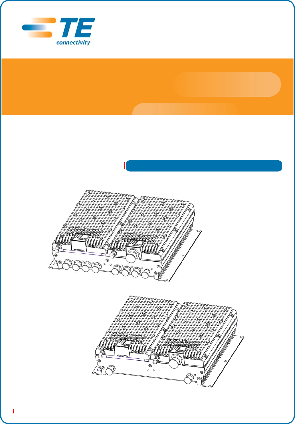
InterReach Spectrum™
Remote Access Unit
Installation Guide - Preliminary Update - Issue 3
Main Remote Access Unit
Secondary Remote Access Unit
Copyright
© 2012 TE Connectivity, Inc. All Rights Reserved.
Information contained in this document is company private to TE Connectivity Ltd., and
shall not be modified, used, copied, reproduced or disclosed in whole or in part without
the written consent of TE.
Trademark Information
FlexWave, FlexWave Prism, InterReach Spectrum, Universal Radio Head, TE
Connectivity, and TE connectivity (logo) are trademarks.
All other logos, products and/or company names referred to herein might be
trademarks of their respective owners.
Disclaimer of Liability
Contents herein are current as of the date of publication. TE reserves the right to change
the contents without prior notice. Should the content of printed user documentation
shipped with product differ from documentation provided on a product CD (inclusive of
the associated Help modules), the printed user documentation supersedes the
documentation on the product CD. In no event shall TE be liable for any damages
resulting from loss of data, loss of use, or loss of profits, and TE further disclaims any
and all liability for indirect, incidental, special, consequential or other similar damages.
This disclaimer of liability applies to all products, publications and services during and
after the warranty period.
Specific Disclaimer for High-Risk Activities
This Product is not specifically designed, manufactured, tested or intended for use in
high-risk activities including, without restricting the generality of the foregoing, on-line
control of aircraft, air traffic, aircraft navigation or aircraft communications; or in the
design, construction, operation or maintenance of any nuclear facility. TE (including its
affiliates) and its suppliers specifically disclaim any express or implied warranty of
fitness for such purposes or any other purposes.
Screenshots in User Documentation
Due to concurrent development of this documentation, artwork, and the InterReach
Spectrum Element Management System (EMS), there may be some minor discrepancies
between screenshots contained in this documentation and those actually displayed in
the InterReach Spectrum EMS. These discrepancies will generally be few and minor and
should not affect your understanding of InterReach Spectrum EMS.

InterReach Spectrum Remote Access Unit Installation Guide - Preliminary Update for Issue 3 Page 1
ADCP-77-168 • Issue 3 • December 2011 ©2012 TE Connectivity Ltd.
TABLEOFCONTENTS
Preface .................................................................................................................................................................2
RevisionHistory...................................................................................................................................................... 2
InterReachSpectrumUserDocumentation ........................................................................................................... 3
StandardsCertification........................................................................................................................................... 4
ProductOverview.................................................................................................................................................5
MainRemoteAccessUnits..................................................................................................................................... 6
MRAUPorts,Cable,andConnectors ..................................................................................................................................6
MRAULEDs .........................................................................................................................................................................7
SecondaryRemoteAccessUnits ............................................................................................................................ 8
SRAUPorts,Cable,andConnectors....................................................................................................................................8
SRAULEDs...........................................................................................................................................................................9
RAUNConnectors................................................................................................................................................ 10
InstalltheRAUsandAntennas............................................................................................................................11
MounttheRAUsandAntennas............................................................................................................................ 11
GeneralSafetyPrecautions .................................................................................................................................. 11
ConnecttheIFEUtotheMRAU............................................................................................................................12
ConnecttheMRAUtoSRAUs ............................................................................................................................... 14
ConfiguretheMRAUsandSRAUs......................................................................................................................... 15
AppendixA:Specifications..................................................................................................................................16
RemoteAccessUnitSpecifications ...................................................................................................................... 16
SpectrumSystemSpecifications........................................................................................................................... 16
CompositePowerOutofRAU .............................................................................................................................. 18
AppendixB:75‐OhmCATVCable........................................................................................................................19
CATVCableRequirements.................................................................................................................................... 19
Belden1695ACoaxSpecifications ....................................................................................................................... 20
Description .......................................................................................................................................................................20
OverallPhysicalCharacteristics ........................................................................................................................................20
OverallNominalElectricalCharacteristics........................................................................................................................21
Belden7732ACoaxSpecifications ....................................................................................................................... 22
Description .......................................................................................................................................................................22
OverallPhysicalCharacteristics ........................................................................................................................................22
OverallNominalElectricalCharacteristics........................................................................................................................23
AppendixC:OmniAntenna.................................................................................................................................24
AppendixD:ContactingTEConnectivity .............................................................................................................25

Preface
Page 2 InterReach Spectrum Remote Access Unit Installation Guide - Preliminary Update for Issue 3
© 2012 TE Connectivity Ltd ADCP-77-168 • Issue 3 • December 2011
PREFACE
ThismanualprovidesinstallationinstructionsforInterReachSpectrum®RemoteAccessUnits
(RAUs).Table1liststheRAUsthataresupportedinthisdocument.
Table1.SupportedSpectrumRemoteAccessUnits
Catalog Number Description
SPT-M1-8519-1 SPECTRUM, 850-1900 MAIN RAU
SPT-M1-AWS19-11 SPECTRUM, 2100AWS Path 1-1900 Path 1 MAIN RAU
SPT-S1-2121-1-MIMO SPECTRUM, 2100AWS MIMO SECONDARY RAU
SPT-S1-7070-1-MIMO SPECTRUM, 700 MIMO SECONDARY RAU, UpperC-LowerABC
SPT-S1-8019-22 SPECTRUM, 800 Path 2-1900 Path 2 SECONDARY RAU
SPT-S1-8090-1 SPECTRUM, 800-900 SMR SECONDARY RAU
SPT-S1-80AWS-1 SPECTRUM, 800-2100AWS Path 1 SECONDARY RAU
SPT-S1-8519-22 SPECTRUM, 850 Path 2-1900 Path 2 SECONDARY RAU
SPT-S1-AWS19-12 SPECTRUM, 2100AWS Path 1-1900 Path 2 SECONDARY RAU
SPT-S2-70AWS-1-SISO SPECTRUM, 700 SISO-2100AWS Path 1 SEC RAU, UpperC-LowerABC
SPT-S2-70AWS-22-SISO SPECTRUM, 700 Path 2 SISO-2100AWS Path 2 SEC RAU, UpperC-LowerABC
RevisionHistory
Issue Document Date Technical Updates
1September 2010 Original
2December 2011 Added “Supported Spectrum Remote Access Units” on page 2, “RAU N Connectors” on page 10, and
“Nominal Passband Gains” on page 17. Updated “Appendix D: Contacting TE Connectivity” on
page 25.
3June 2012 Updated IC standards in “Standards Certification” on page 4; updated “Composite Power Out of RAU”
on page 18.

InterReach Spectrum User Documentation
InterReach Spectrum Remote Access Unit Installation Guide - Preliminary Update for Issue 3 Page 3
ADCP-77-168 • Issue 3 • December 2011 © 2012 TE Connectivity Ltd.
InterReachSpectrumUserDocumentation
TheInterReachSpectrumuserdocumentationisintendedforsystemadministrators,engineers
andinstallersresponsibleforplanning,administering,configuring,andmaintainingTE
ConnectivityInterReachSpectrumsystems.Table2liststhemanualsthatcorrespondtothis
InterReachSpectrumrelease.
Table2.InterReachSpectrumUserDocumentation
Title ADCP Number
InterReachSpectrumQuickStartGuide ADCP-77-165
InterReachSpectrumHostUnitInstallationGuide ADCP-77-166
InterReachSpectrumExpansionModuleGroup
InstallationGuide
ADCP-77-167
InterReachSpectrumRemoteAccessUnitInstallation
Guide
ADCP-77-168
InterReachSpectrumElementManagementSystem7.2
UserManual
ADCP-77-189
FlexWavePrismOADMSpliceBoxInstallationGuide ADCP-77-151
Twotypesofmessages,identifiedbelow,appearintheInterReachSpectrumuserdocumentation:
CAUTION! Cautiontextindicatesoperationsorstepsthatcouldcausepersonalinjury,induceasafety
probleminamanageddevice,destroyorcorruptinformation,orinterruptorstopservices.
NOTE: Notetextcontainsinformationaboutspecialcircumstances.

Preface
Page 4 InterReach Spectrum Remote Access Unit Installation Guide - Preliminary Update for Issue 3
© 2012 TE Connectivity Ltd ADCP-77-168 • Issue 3 • December 2011
StandardsCertification
FCC:ThisequipmentcomplieswiththeapplicablesectionsofTitle47CFR,Part22(800MHz
Cellular),Part24(1900MHz‐PCS),Part90(800/900‐SMR),andPart27(700MHz,2100MHz
‐AWS).
IC:ThisequipmentcomplieswiththeapplicablesectionsofRSS‐131(800/900–SMR),RSS‐132
(800‐Cellular),andRSS‐133(1900–PCS).Theterm“IC:”beforetheradiocertificationnumber
onlysignifiesthatIndustryCanadaTechnicalSpecificationsweremet.
TheManufacturer'sratedoutputpowerofthisequipmentisforsinglecarrieroperation.For
situationswhenmultiplecarriersignalsarepresent,theratingwouldhavetobereducedby3.5
dB,especiallywheretheoutputsignalisre‐radiatedandcancauseinterferencetoadjacentband
users.Thispowerreductionistobebymeansofinputpowerorgainreductionandnotbyan
attenuatorattheoutputofthedevice.
NOTE: TheU.S.FederalCommunicationsCommission(FCC)hasdevelopedguidelinesforevaluationof
humanexposuretoRFemissions.TheguidelinesincorporatelimitsforMaximumPermissible
Exposure(MPE)forpowerdensityoftransmitteroperatingatfrequenciesbetween300kHzand
100GHz.Limitshavebeensetforportable,mobile,andfixedequipment.TEConnectivity
productsfallinthecategoryoffixedequipment;productsintendedtobepermanentlysecured
andexposuresareevaluatedfordistancesgreaterthan40cm(15.75”).Portabledevicesfallinto
exposuresoflessthan20cm,whereSARevaluationsareused.
Antennagainisrestrictedto1.5WERP(2.49WEIRP)inordertosatisfyRFexposure
compliancerequirements.Ifhigherthan1.5WERP,routineMPEevaluationisneeded.
Theantennasshouldbeinstalledtoprovideatleast40cmfromallpersonstosatisfy
MPErequirementsofFCCPart2,2.1091.
UL/CUL:Thiswillbeinstalledinarestrictedaccesslocation.Thisequipmentcomplies,perUL
andCUL50,StandardforEnclosuresforElectricalEquipment.
UL/CUL:ThisequipmentcomplieswithULandCUL60950‐1StandardforSafetyforInformation
TechnologyEquipment,includingElectricalBusinessEquipment.
UL/CUL:AllInterReachSpectrumRAUsarePlenumratedandsuitableforuseinenvironmental
airspaceinaccordancewithSection300‐22(C)oftheNationalElectricalCode,andSections
2‐128,12‐010(3)and12‐100oftheCanadianElectricalCode,Part1,CSAC22.1.
UL:ThisequipmentisULPlenumratedunderUL2043.
CAUTION! Modificationsnotexpresslyapprovedbythepartyresponsibleforcompliancecouldvoidthe
user'sauthoritytooperatetheequipment.
Standards Certification
InterReach Spectrum Remote Access Unit Installation Guide - Preliminary Update for Issue 3 Page 5
ADCP-77-168 • Issue 3 • December 2011 © 2012 TE Connectivity Ltd.
PRODUCTOVERVIEW
InterReachSpectrumsupportsuptoeightfrequencybandsinasinglesystem.Eachantenna
locationsupportsthosebandsinmodular,grouppairings.EachlocationincludesaMainRemote
AccessUnit(MRAU),whichcanpoweruptothreeadditionalSecondaryRemoteAccessUnits
(SRAUs).AnMRAUsupportstwofrequencybands,andeachSRAUcansupportuptotwo
frequencybands,foratotalofuptoeightfrequencybands.MRAUsandSRAUsaregrouped
logically,basedoncommonserviceprovidergroupingsandinclude,asanexample:
•850/1900
•700/700MIMO
•800/900SMR
•1900/AWS.
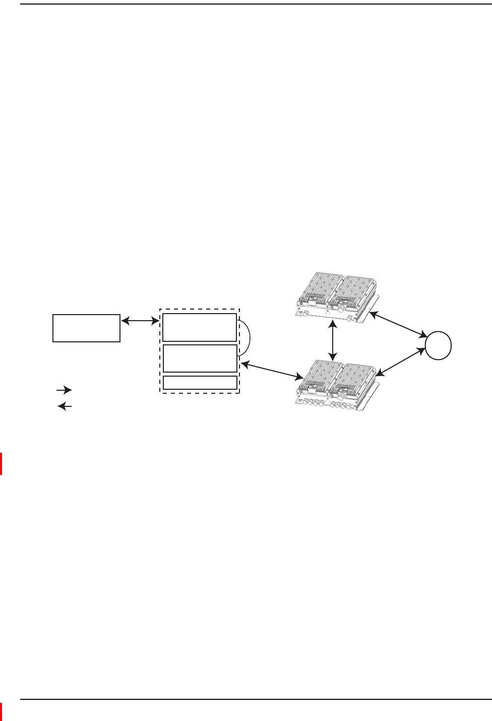
Toaddmorefrequencybands,youconnectanSRAUtotheexistingMRAU.Figure1illustrates
howRFandIFsignalsaresentbetweenSpectrumunitsandmodules.
Omni Antenna
Host
Power Supply
IF Expansion Unit
DART Remote Unit
Expansion Module Group
Secondary Remote Access Unit
Main Remote Access Unit
IF
RF
RF
IF
Reverse (REV)
Forward (FWD)
Key to Signal Path
RF
IF
Figure1.REV and FWD Signals for the RAU
NOTE: ThisbookreferstotheOmniAntenna(4214‐M727),whichistheantennathatTEConnectivity
recommends.Otherantennasmaybeused.ForfurtherinformationontheOmniAntenna,see
“AppendixC:OmniAntenna”onpage24.
Product Overview
Page 6 InterReach Spectrum Remote Access Unit Installation Guide - Preliminary Update for Issue 3
© 2012 TE Connectivity Ltd ADCP-77-168 • Issue 3 • December 2011
MainRemoteAccessUnits
TheMainRemoteAccessUnit(MRAU)receivesFWDIFsignalsfromanIFExpansionUnit(IFEU),
whichispartoftheSpectrumExpansionModuleGroup,using75CATVcable.TheMRAU
convertstheIFsignalstoRFandsendsthemtoapassiveRFantennausing50coaxialcable.The
MRAUalsoreceivesconfigurationinformationandpowerfromandsendsitsstatusinformation
totheIFEU.
TheMRAUreceivesREVRFsignalsfromapassiveRFantennausing50coaxialcable.Itconverts
thesignalstoIFandsendsthemtotheIFEUusing75CATVcable.
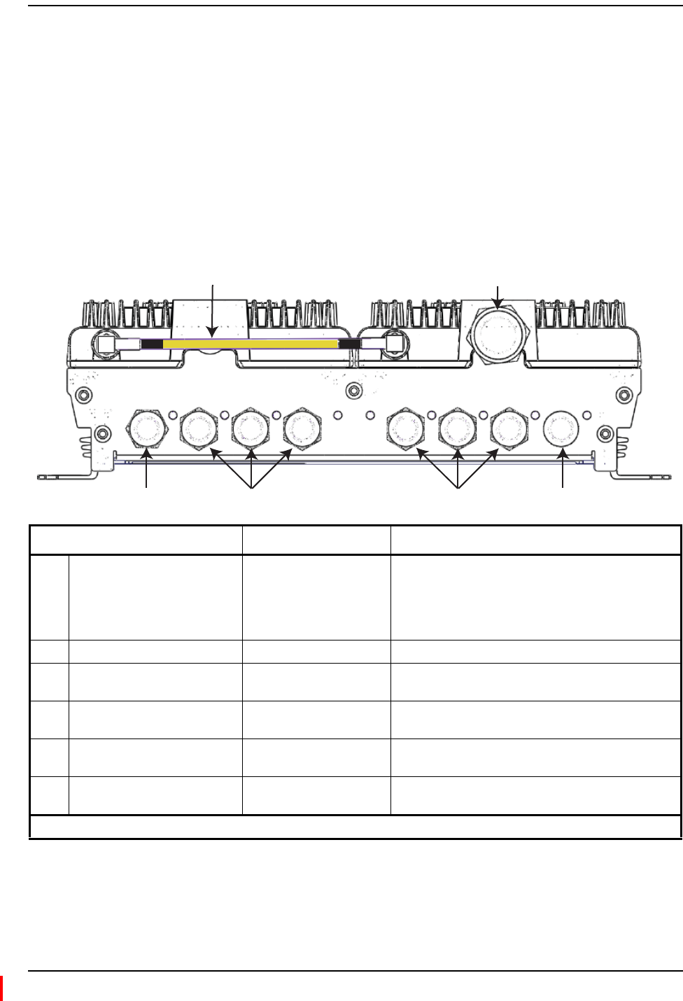
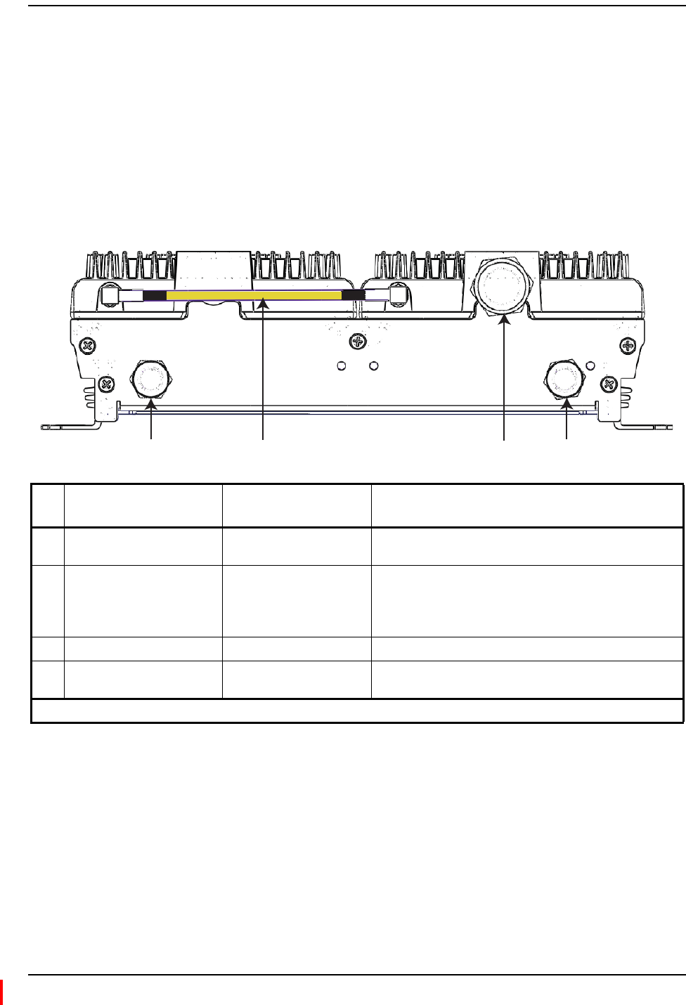
MRAUPorts,Cable,andConnectors
REV IF OUT REV SECONDARY PORTS
1 2 3
FWD SECONDARY PORTS
1 2 3
FWD IF IN
LINK STATUS
1 2
36 54
Ref # Component Device Function
1RF SubMiniature version A
(SMA) cable (1)
50 RF SMA-to-SMA cable Connects two RF bands together when there is only one
N-type connector on the RAU.
For cases when there is an N-type connector for each RF
band (700MIMO or PCS/AWS), there will not be an SMA
cable.
2Antenna port(s) 50 N-type connector Connects to an antenna. See Table 3 on page 10.
3FWD IF IN connector F connector port Connects to the IFEU FWD Module IF OUT connector via
CATV cable.
4FWD SECONDARY PORTS (1 - 3) F connector ports Connect to a SRAU SECONDARY FWD connector via
CATV cable.
5REV SECONDARY PORTS (1 - 3) F connector ports Connect to a SRAU SECONDARY REV connector via
CATV cable.
8REV IF OUT connector F connector port Connects to the IFEU REV Module IF IN connector via
CATV cable.
(1) The AWS/PCS MRAUs does NOT have an RF SMA cable, and has two Antenna ports.
Main Remote Access Units
InterReach Spectrum Remote Access Unit Installation Guide - Preliminary Update for Issue 3 Page 7
ADCP-77-168 • Issue 3 • December 2011 © 2012 TE Connectivity Ltd.
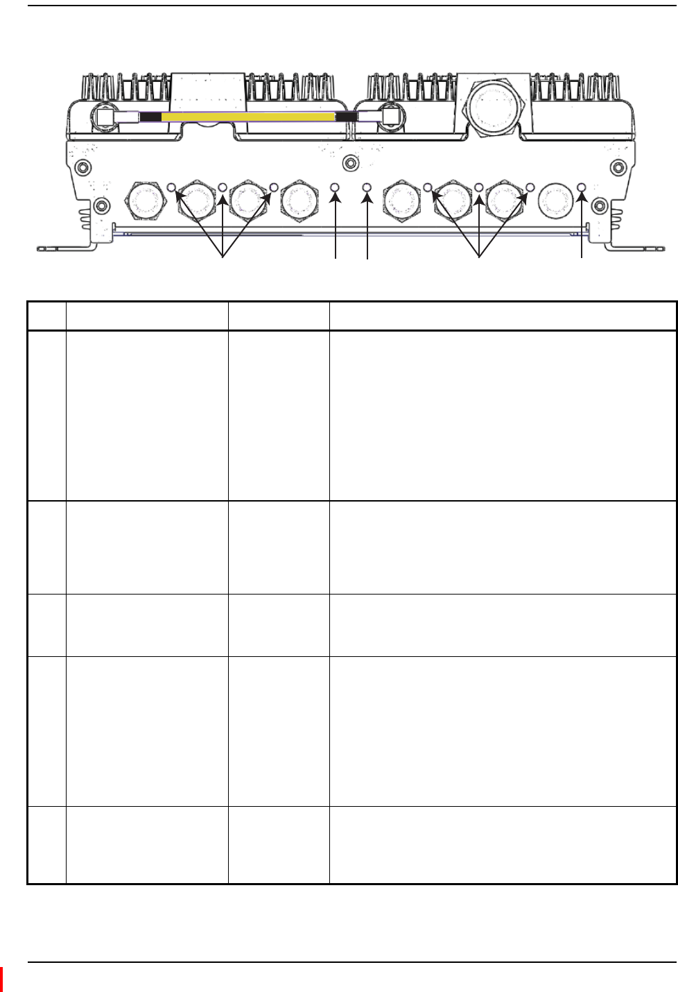
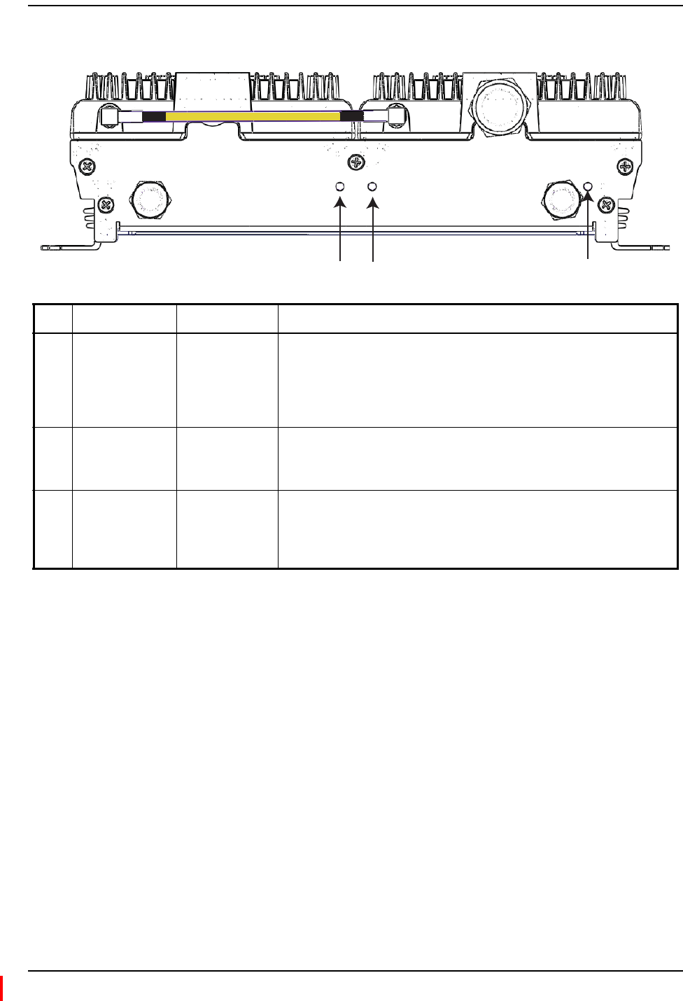
MRAULEDs
REV IF OUT REV SECONDARY PORTS
1 2 3
FWD SECONDARY PORTS
1 2 3
FWD IF IN
LINK STATUS
41 5
2 3
Ref # LED LED Color Description
1FWD SECONDARY PORT
(1 - 3)
2LINK
3STATUS
4REV SECONDARY PORT
(1 - 3)
5FWD IF IN
• Green • Downstream unit correctly connected; unit has no alarms or a
Minor alarm is active.
• Blinking Green • SRAU or band is set out-of-service.
• Yellow • FWD cable connected to SRAU, no REV cable connected.
• Blinking Yellow • FWD and REV cables are not connected to the same port number
(incorrectly paired).
• Red • Major alarm in downstream unit, fault lockout, or SRAU
disconnected.
• Off • No SRAU previously connected.
•Green •MRAU receiving communications from the IFEU.
• Red • MRAU has not received communications from the IFEU for more
than 90 seconds.
• Off • During initial power up, MRAU is powering up and waiting for IFEU
communications.
• Green • Unit has no alarms or a Minor alarm is active.
• Blinking Green • Unit or band is set out-of-service.
• Red • Major alarm detected.
• Green • Downstream unit correctly connected, unit has no alarms or minor
alarm
• Blinking Green • SRAU or band is set out-of-service.
• Blinking Yellow • FWD and REV cables are not connected to the same port number
(incorrectly paired).
• Red • Major alarm in downstream unit, fault lockout, or SRAU
disconnected.
• Off • No SRAU previously connected.
• Green • MRAU is powered on correctly.
•Y
ellow or
Blinking Yellow
• There is an IFEU FWD connection, but there is no IFEU REV
connection or the IFEU REV connection is paired incorrectly.
• Off • Cable is not connected to the IFEU FWD port.
Product Overview
Page 8 InterReach Spectrum Remote Access Unit Installation Guide - Preliminary Update for Issue 3
© 2012 TE Connectivity Ltd ADCP-77-168 • Issue 3 • December 2011
SecondaryRemoteAccessUnits
ASecondaryRemoteAccessUnit(SRAU)receivesFWDIFsignalsfromtheMRAU,using75
CATVcable.TheSRAUconvertstheIFsignalstoRFandsendsthemtoapassiveRFantennausing
50coaxialcable.TheSRAU,throughtheMRAU,alsoreceivesconfigurationinformationand
powerfromandsendsitsstatusinformationtotheIFEU.
TheSRAUreceivesREVRFsignalsfromapassiveRFantennausing50coaxialcable.Itconverts
thesignalstoIFandsendsthemtotheMRAUusing75CATVcable.
SRAUPorts,Cable,andConnectors
1 4
LINK STATUS
SECONDARY
REV
SECONDARY
FWD
2
3
Ref
#
Component Device Function
1SECONDARY REV connector F connector port Connects to one of the MRAU REV SECONDARY ports (1 - 3)
via CATV cable.
2RF SMA cable (1)
50 RF SMA-to-SMA cable
Connects two RF bands together when there is only one
N-type connector on the RAU.
For cases when there is an N-type connector for each RF band
(700MIMO or PCS/AWS), there will not be an SMA cable.
3Antenna port(s) 50 N-type connector Connects to an antenna. See Table 3 on page 10.
4SECONDARY FWD connector F connector port Connects to one of the MRAU FWD SECONDARY ports (1 - 3)
via CATV cable.
(1) The 700 MIMO SRAUs does NOT have an RF SMA cable, and has two Antenna ports.
Secondary Remote Access Units
InterReach Spectrum Remote Access Unit Installation Guide - Preliminary Update for Issue 3 Page 9
ADCP-77-168 • Issue 3 • December 2011 © 2012 TE Connectivity Ltd.
SRAULEDs
LINK STATUS
SECONDARY
REV
SECONDARY
FWD
21 3
Ref # LED LED Color Description
1 LINK
2STATUS
3SECONDARY FWD
•Green •SRAU receiving communications from the IFEU.
• Red • SRAU has not received communications from the IFEU for more than 90
seconds.
• Off • During initial power up, SRAU is powering up and waiting for IFEU
communications.
• Green • Unit has no alarms or a Minor alarm is active.
•Blinking Green • Unit or band is set out-of-service.
• Red • Major alarm detected.
• Green • SRAU is powered on correctly.
•Y
ellow or
Blinking Yellow
• There is an MRAU FWD connection, but there is no MRAU REV connection
or the MRAU REV connection is paired incorrectly.
• Off • Cable is not connected to the MRAU FWD port.

Product Overview
Page 10 InterReach Spectrum Remote Access Unit Installation Guide - Preliminary Update for Issue 3
© 2012 TE Connectivity Ltd ADCP-77-168 • Issue 3 • December 2011
RAUNConnectors
EachRAUalsohasoneortwo50‐N‐typeconnectorsthatconnecttoapassiveantenna.Table3
liststhenumberofN‐typeconnectorsavailableoneachRAUmodel.
Table3.NumberofNConnectorsonRAUs
Catalog Number Description Number of RF
N Connectors*
SPT-M1-8519-1 SPECTRUM, 850-1900 MAIN RAU 1
SPT-M1-AWS19-11 SPECTRUM, 2100AWS Path 1-1900 Path 1 MAIN RAU 2
SPT-S1-2121-1-MIMO SPECTRUM, 2100AWS MIMO SECONDARY RAU 2
SPT-S1-7070-1-MIMO SPECTRUM, 700 MIMO SECONDARY RAU, UpperC-LowerABC 2
SPT-S1-8019-22 SPECTRUM, 800 Path 2-1900 Path 2 SECONDARY RAU 1
SPT-S1-8090-1 SPECTRUM, 800-900 SMR SECONDARY RAU 1
SPT-S1-80AWS-1 SPECTRUM, 800-2100AWS Path 1 SECONDARY RAU 1
SPT-S1-8519-22 SPECTRUM, 850 Path 2-1900 Path 2 SECONDARY RAU 1
SPT-S1-AWS19-12 SPECTRUM, 2100AWS Path 1-1900 Path 2 SECONDARY RAU 2
SPT-S2-70AWS-1-SISO SPECTRUM, 700 SISO-2100AWS Path 1 SEC RAU, UpperC-LowerABC 1
SPT-S2-70AWS-22-SISO SPECTRUM, 700 Path 2 SISO-2100AWS Path 2 SEC RAU, UpperC-LowerABC 1
* There are two bands per RAU, which results in two N connectors. When there is one N connector, the two bands are
combined internally and both bands use the single N connector.

Mount the RAUs and Antennas
InterReach Spectrum Remote Access Unit Installation Guide - Preliminary Update for Issue 3 Page 11
ADCP-77-168 • Issue 3 • December 2011 © 2012 TE Connectivity Ltd.
INSTALLTHERAUSANDANTENNAS
FollowthestepsintheorderprovidedtoinstalltheRAUsandantennas.
MounttheRAUsandAntennas
GeneralSafetyPrecautions
CAUTION! Wetconditionsincreasethepotentialforreceivinganelectricalshockwheninstallingorusing
electricallypoweredequipment.Topreventelectricalshock,neverinstalloruseelectrical
equipmentinawetlocationorduringalightningstorm.
CAUTION! ThissystemisaRFTransmitterandcontinuouslyemitsRFenergy.Maintainaminimum8‐inch
(20cm)clearancefromtheantennawhilethesystemisoperating.Wheneverpossible,shut
downtheRANbeforeservicingtheantenna.
NOTE: RAUsaresuitableforuseinenvironmentalairspaceinaccordancewithSection300‐22(c)ofthe
NationalElectricalCode,andSections2‐128,12‐010(3)and12‐100oftheCanadianElectrical
Code,Part1,CSAC22.1.
CAUTION! InstallRAUsinindoorlocationsonly.Donotconnectanantennainstalledinanoutdoorlocation
toaRAU,unlessitisinanapprovedAOCweatherproofNEMA4housing.
CAUTION! AttachallRAUssecurelytoastationaryobject(thatis,awall,pole,orceilingbrackets).Tomount
aRAUsecurelytoawall,ceilingbracket,orpole,use#6diameterfastenersinthefourslotted
mountingholes.
CAUTION! Dothefollowingtomaintainproperventilation:
•Keepatleast76mm(3‐inch)clearancearoundtheRAU.
•DonotstackRAUsontopofeachother.
•AlwaysmounttheRAUwiththesolidface(containingthemountingholes)againstthe
mountingsurface.
NOTE: YoucanplacetheRAU,withoutitsfasteninghardware,onaflatsurface,suchasashelf,desk,
cabinet,oranyotherhorizontalsurfacethatallowsstableplacement,withthemountingbase
facingdowntothemountingsurface.
CAUTION! IfinstallingtheRAUonaflatsurface,thesurfacemustbeabletoholdaminimum7‐poundload
securely.
Dothefollowing,intheorderpresented,tomounttheRAUsandantennas:
1MountallMRAUandSRAUsinthelocationsmarkedonthefloorplans.
2Installthepassiveantennasaccordingtothemanufacturer’sinstallationinstructions.
NOTE: Itiscommonpracticetoinstallpassiveantennasbelowtheceiling.Ifyouinstallapassive
antennaabovetheceiling,whenestimatingtheantennacoveragearea,accountforadditional
lossduetotheceilingmaterial.
Install the RAUs and Antennas
Page 12 InterReach Spectrum Remote Access Unit Installation Guide - Preliminary Update for Issue 3
© 2012 TE Connectivity Ltd ADCP-77-168 • Issue 3 • December 2011
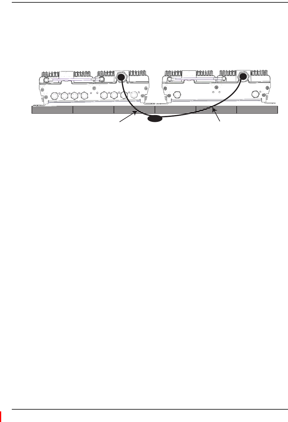
3Connectapassivemulti‐bandantennatotheNconnectoroneachRAUusingcoaxialcable
withtheleastamountoflosspossible.(See“AppendixC:OmniAntenna”onpage24for
informationontheOmniAntennaports.)
Omni Antenna
False Ceiling
SRAU N1
REV IF OUT REV SECONDARY PORTS
1 2 3
FWD SECONDARY PORTS
1 2 3
FWD IF IN
LINK STATUS
LINK STATUS
SECONDARY
REV
SECONDARY
FWD
MRAU N1
Coaxial cable
Coaxial cable
CAUTION! Firmlyhand‐tightentheNconnector.DONOTover‐tightentheconnector.
ConnecttheIFEUtotheMRAU
NOTE: TheIFEUshouldbepoweredupbeforestartingthisprocedure;seetheInterReachSpectrum
ExpansionModuleGroupInstallationGuide(ADCP‐77‐167).
4FollowtheserulesfortheCATVcableswhenconnectingtheIFEUtotheMRAU:
•TheFWDandREVcablesshouldbeclosetothesamelength.
•TheFWDandREVcablesshouldbethesamecabletype(bothRG6orbothRG11).
•ApairofCATVcablesconnectseachMRAUtotheIFEU.TheIFEUREVModuleIFINport
andtheIFEUFWDModuleIFOUTportmustmatch.Forexample,ifIFEUREVModuleIF
INPort3isused,useIFEUFWDModuleIFOUTPort3.
•Referto“AppendixB:75‐OhmCATVCable”onpage19forinformationonmaximumRG‐6
orRG‐11CATVcablelengths.
5TestthecableterminationforeachCATVcablebeforeinstallingit.
6ConnectFconnectorCATVcablesontheIFEUandMRAU,intheordergivenbelow.
IftheLEDsdonotperformasdescribedinthisprocedure,referto“MRAULEDs”onpage7.
aConnectaCATVcablefromoneoftheIFEUFWDModuleIFOUTconnectors(1‐8)tothe
MRAUFWDIFINconnector.
bConfirmthattheMRAUFWDIFINLEDisyellow,whichindicatesacorrectphysical
connection.
cConnectaCATVcablefromtheIFEUREVModuleIFINconnector(1‐8)totheMRAUREV
IFOUTconnector,makingsurethatyoupairtheportusedtothesameportnumber
selectedinStep6a.
Iftheconnectioniscorrect,theMRAUpowersupandtheMRAUFWDIFINLEDturns
green.
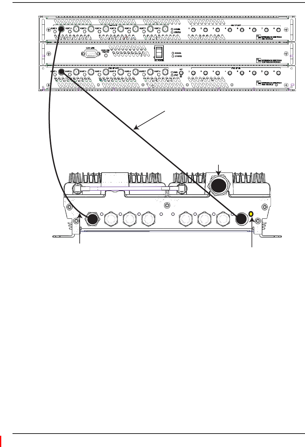
IFEU
Step 6a
REV IF OUT REV SECONDARY PORTS
1 2 3
FWD SECONDARY PORTS
1 2 3
FWD IF IN
LINK STATUS
To an antenna
MRAU
Step 6b
Step 6c
Connect the IFEU to the MRAU
InterReach Spectrum Remote Access Unit Installation Guide - Preliminary Update for Issue 3 Page 13
ADCP-77-168 • Issue 3 • December 2011 © 2012 TE Connectivity Ltd.
Install the RAUs and Antennas
Page 14 InterReach Spectrum Remote Access Unit Installation Guide - Preliminary Update for Issue 3
© 2012 TE Connectivity Ltd ADCP-77-168 • Issue 3 • December 2011
ConnecttheMRAUtoSRAUs
CAUTION! Topreventinterference,donotinstallan850/1900MRAUantennanearan800/900SRAU.The
850MHzbandmustbe20feetawayfromthe800/1900SRAU’spassiveantenna.
7Useoneofthefollowing6’and20’CATVRG6jumpers,availableforpurchasefromTE
Connectivity,toconnectanMRAUtoSRAUs.
TE Connectivity
Part Number
Description Note
300469-0 6’ RG-6 Cable; F Male to F Male CATV cable that connects the MRAU to SRAUs. Two
cables required per SRAU.
300469-1 20’ RG-6 Cable; F Male to F Male CATV cable that connects the MRAU to SRAUs. Two
cables required per SRAU.
8TestthecableterminationforeachCATVcablebeforeinstallingit.
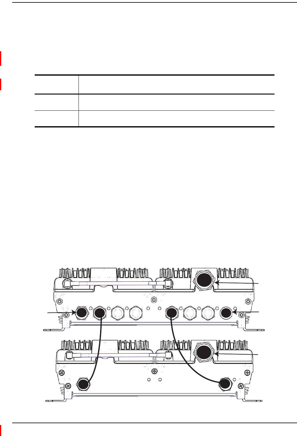
9ConnectFconnectorCATVcablesfromtheMRAUtoanSRAU,intheordergivenbelow.Ifthe
LEDsdonotperformasdescribedinthisprocedure,referto“SRAULEDs”onpage9.
aConnectaCATVcablefromanMRAUFWDSECONDARYPORT(1,2,or3)Fconnectorto
theSRAUSECONDARYFWDFconnector.
bConfirmthattheSRAUSECONDARYFWDLEDisyellow,whichindicatesacorrect
physicalconnection.
cConnectaCATVcablefromanMRAUREVSECONDARYPORT(1,2,or3)Fconnectorto
theSRAUSECONDARYREVFconnector,matchingthesameportnumberselectedinStep
9a.Thatis,ifinStep9ayouconnectedanFconnectortotheMRAUFWDSECONDARY
PORT1,thepairedCATVcablemustconnecttotheMRAUREVSECONDARYPORT1.
Iftheconnectioniscorrect,theSRAUpowersupandtheSRAUSECONDARYFWDLED
turnsgreen.
REV IF OUT REV SECONDARY PORTS
1 2 3
FWD SECONDARY PORTS
1 2 3
FWD IF IN
LINK STATUS
LINK STATUS
SECONDARY
REV
SECONDARY
FWD
To an IFEU REV
Module IF IN
connector (1 - 8)
To an IFEU FWD
Module IF OUT
connector (1 - 8)
MRAU
SRAU To an antenna
To an antenna
Configure the MRAUs and SRAUs
InterReach Spectrum Remote Access Unit Installation Guide - Preliminary Update for Issue 3 Page 15
ADCP-77-168 • Issue 3 • December 2011 © 2012 TE Connectivity Ltd.
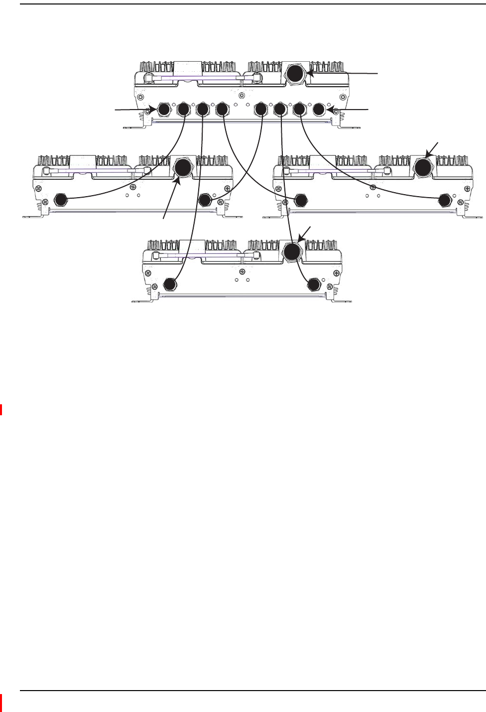
10 RepeatStep9toinstalluptotwomoreSRAUs,aspersystemdesign.
REV IF OUT REV SECONDARY PORTS
1 2 3
FWD SECONDARY PORTS
1 2 3
FWD IF IN
LINK STATUS
LINK STATUS
SECONDARY
REV
SECONDARY
FWD
LINK STATUS
SECONDARY
REV
SECONDARY
FWD
LINK STATUS
SECONDARY
REV
SECONDARY
FWD
MRAU
SRAU1
SRAU2
SRAU3
To an IFEU FWD Module
IF OUT connector (1 - 8)
To an IFEU REV Module
IF IN connector (1 - 8)
To an antenna
To an antenna
To an antenna
To an antenna
ConfiguretheMRAUsandSRAUs
RefertotheInterReachSpectrum™ElementManagementSystem7.0UserManual(ADCP‐77‐163)
forinformationonhowtoconfiguretheMRAUsandSRAUs.

Appendix A: Specifications
Page 16 InterReach Spectrum Remote Access Unit Installation Guide - Preliminary Update for Issue 3
© 2012 TE Connectivity Ltd ADCP-77-168 • Issue 3 • December 2011
APPENDIXA:SPECIFICATIONS
RemoteAccessUnitSpecifications
OperatingTemp ‐25°Cto+50°C
StorageTemperature ‐40°Cto+70°C
Humidity 10%to90%non‐condensing
Dimensions 11.50"x9.00"x3.50"
Weight 7.49Pounds
PowerSource +54Vdc(fromIFEU)
SpectrumSystemSpecifications
RFSpecification
SupportedFrequencyBlocks 2perRemoteAntennaUnit;1‐8perHostUnit
Bandwidth 1.5to75MHznon‐contiguous
FrequencyBandSupported 850Cellular;800iDEN;900iDEN;1900PCS;2100AWS;
700UpperCLowerABC
PropagationDelay
SystemDelay <12microseconds
DelayManagementDigital (ManualorAutomatic)
NoiseFigure
NoiseFigure For1Host,1DRU,8RAUs:<17dB
For1Host,4DRUs,32RAUs:<23dB
InputIP3 >‐10dBm
OpticalSpecifications
OpticalBudget 10dB(Standard);26dB(Optional)
DigitalTransportRate 3.072Gbps

RF Frequency
TX RX
850 Cell
Bandwidth 869-894 824-849
Gain (dB) 40 30
800 SMR
Bandwidth 851-869 806-824
Gain (dB) 40 30
900 SMR
Bandwidth 935-940 896-901
Gain (dB) 40 30
1900 PCS
Bandwidth 1930-1995 1850-1915
Gain (dB) 40 30
2100 AWS
Bandwidth 2110-2155 1710-1755
Gain (dB) 40 30
700 Upper C
Bandwidth 746-756 776-786
Gain (dB) 40 30
700 Lower ABC
Bandwidth 728-746 698-716
Gain (dB) 40 30
Spectrum System Specifications
InterReach Spectrum Remote Access Unit Installation Guide - Preliminary Update for Issue 3 Page 17
ADCP-77-168 • Issue 3 • December 2011 © 2012 TE Connectivity Ltd.
NominalPassbandGains
OutputPower
OutputP1dBPowerperBand 26dBm850MHzCell
26dBm1900MHzPCS
26dBm700MHzUpperCLowerABC
26dBm2100MHzAWS
26dBm800iDEN
26dBm900iDEN

Appendix A: Specifications
Page 18 InterReach Spectrum Remote Access Unit Installation Guide - Preliminary Update for Issue 3
© 2012 TE Connectivity Ltd ADCP-77-168 • Issue 3 • December 2011
CompositePowerOutofRAU
RF Frequency Number of RF Carriers
TX RX 1 2 4 8 16
850 Cell 869-894 824-849 26.0 20.0 14.0 9.0 5.5 GSM
23.0 17.5 12.0 8.0 5.0 EDGE
18.0 15.0 12.0 9.0 6.0 CDMA
18.0 15.0 12.0 9.0 WCDMA
18.0 15.0 12.0 9.0 LTE
800 SMR 851-869 806-824 17.5 14.0 10.0 6.5 iDEN
26.0 19.5 13.5 8.5 APCO 25 C4FM
18.0 15.0 12.0 9.0 6.0 CDMA
18.0 15.0 12.0 9.0 LTE
900 SMR 935-940 896-901 17.5 14.0 10.0 6.5 iDEN
26.0 19.5 13.5 8.5 APCO 25 C4FM
18.0 15.0 12.0 9.0 6.0 CDMA
18.0 15.0 12.0 9.0 LTE
1900 PCS 1930-1995 1850-1915 26.0 20.0 14.0 9.0 5.5 GSM
23.0 17.5 12.0 8.0 5.0 EDGE
18.0 15.0 12.0 9.0 6.0 CDMA
18.0 15.0 12.0 9.0 WCDMA
18.0 15.0 12.0 9.0 LTE
2100 AWS 2110-2155 1710-1755 18.0 15.0 12.0 9.0 WCDMA
18.0 15.0 12.0 9.0 LTE
700 Upper C 746-756 776-786 18.0 15.0 12.0 9.0 LTE
700 Lower ABC 728-746 698-716 18.0 15.0 12.0 9.0 LTE
NOTE: IndustryCanada‐24.83dBmratedoutputpowerfor2100MHzAWS
NOTE: IndustryCanada‐46.8MHzDeclaredBandwidthGainfor2100MHzAWS
CATV Cable Requirements
InterReach Spectrum Remote Access Unit Installation Guide - Preliminary Update for Issue 3 Page 19
ADCP-77-168 • Issue 3 • December 2011 © 2012 TE Connectivity Ltd.
APPENDIXB:75‐OHMCATVCABLE
The75‐OhmCATVCable:
•connectstheIFEUtoMRAU(s)andtheMRAU(s)totheSRAU(s)
•transmits(FWD)multibandandreceives(REV)IFsignals
•deliversDCelectricalpowertotheRAUs.TheSpectrumIFEUDCvoltageoutputis+54Vdc
nominal.IftheIFEUreachesitscurrentlimit,acurrent‐limitingcircuitprotectsit.
•carriesconfigurationandstatusinformation
•uses75type‐Fconnectorswithcaptivecenterpins.
CATVCableRequirements
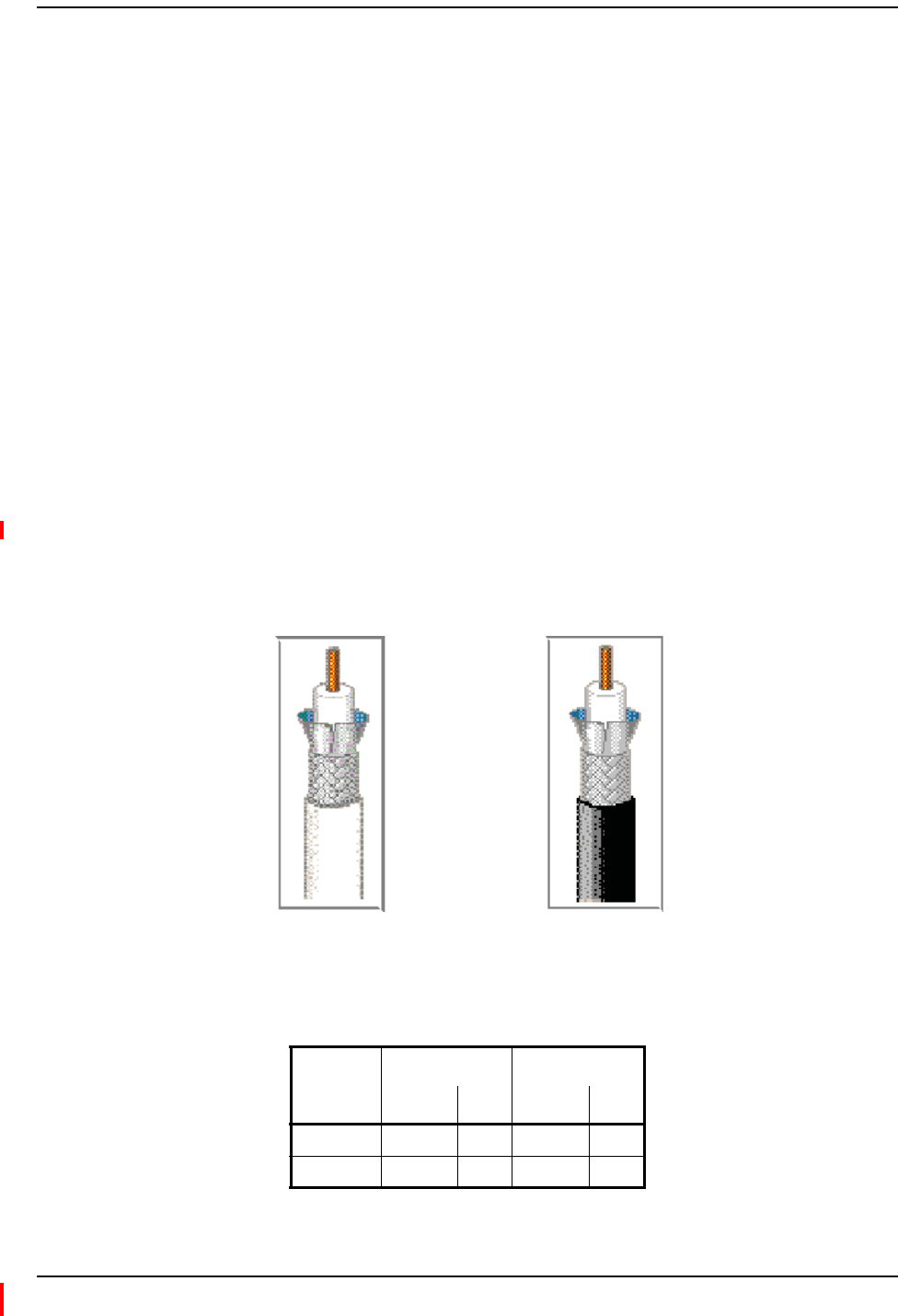
BeldenCATVcableorequivalentisrequired(seeFigure2).
•FortheRG‐6cable,useaBelden1695ACoax.
•FortheRG‐11cable,useaBelden7732ACoax.
RG-11
Belden 1695A Coax
RG-6
Belden 7732A Coax
NOTE: TEConnectivityrequiressolidcoppercenterconductorCATVcableforproperDCvoltagetothe
RAUandmaximumdistances.
Figure2.Belden 1695A and 7732A Coax Cables
•UseRG‐6orRG‐11CATVcablebetweentheIFEUandMRAU,thetypicallengthsofwhichare
listedbelow.
Cable Type
Minimum Length Maximum Length
Meters Feet Meters Feet
RG-6 0 0 140 459
RG-11 0 0 200 656

Appendix B: 75-Ohm CATV Cable
Page 20 InterReach Spectrum Remote Access Unit Installation Guide - Preliminary Update for Issue 3
© 2012 TE Connectivity Ltd ADCP-77-168 • Issue 3 • December 2011
•UseonlyRG‐6CATVcablebetweentheMRAUandSRAU,thelengthsofwhicharelistedbelow.
RG-6 Cable Meters Feet
Typical 26.56
800/900 iDEN to 850 CELL 619.68
800 AWS to 850 CELL 619.68
Belden1695ACoaxSpecifications
Description
RG‐6/Utype,18AWGsolid0.040‐inchbarecopperconductor,plenum,foamFEPinsulation,
Duofoil®+tinnedcopperbraidshield(95%coverage),Flamarrest®jacket.
OverallPhysicalCharacteristics
Conductor OneCoax
18AWG
Solidstranding
BareCopper(BC)conductormaterial
0.040‐inchdiameter
Insulation Teflon®
FoamFluorinatedEthylenePropylene(FFEP)
0.170‐inchdiameter
OuterShieldLayer1Duofoil
®
Tape
AluminumFoil‐PolyesterTape‐AluminumFoil
100%coverage
OuterShieldLayer2Braid
TinnedCopper(TC)
95%coverage
OuterJacket Flamarrest®
LowSmokePolyvinylChloride(LSPVC)
OverallCabling 0.234‐inchoverallnominaldiameter

Belden 1695A Coax Specifications
InterReach Spectrum Remote Access Unit Installation Guide - Preliminary Update for Issue 3 Page 21
ADCP-77-168 • Issue 3 • December 2011 © 2012 TE Connectivity Ltd.
OverallNominalElectricalCharacteristics
CharacteristicImpedance 75.000
Inductance 0.103H/ft.
CapacitanceConductortoShield 16.100(pF/ft.)
VelocityofPropagation 82(%)
Delay 1.240(ns/ft.)
ConductorDCResistance 6.400@20°C(/1000ft.)
OuterShieldDCResistance 2.800@20°C(/1000ft.)
Attenuation
Freq. (MHz) Attenuation (dB/100 ft.)
1.000 0.240
3.580 0.450
5.000 0.550
7.000 0.650
10.000 0.750
67.500 1.740
71.500 1.780
88.500 1.940
100.000 2.100
135.000 2.400
143.000 2.500
180.000 2.800
270.000 3.400
360.000 4.000
540.000 5.200
720.000 6.100
750.000 6.200
1000.000 7.300
1500.000 9.200
2000.000 10.900
2250.000 11.600
3000.000 13.700

Appendix B: 75-Ohm CATV Cable
Page 22 InterReach Spectrum Remote Access Unit Installation Guide - Preliminary Update for Issue 3
© 2012 TE Connectivity Ltd ADCP-77-168 • Issue 3 • December 2011
Belden7732ACoaxSpecifications
Description
RG‐11/Utype,14AWGsolid0.064‐inchbarecopperconductor,plenum,foamFEPinsulation,
Duofoil®+tinnedcopperbraidshield(95%coverage),fluorocopolymerjacket.
OverallPhysicalCharacteristics
Conductor OneCoax
18AWG
Solidstranding
BareCopper(BC)conductormaterial
0.064‐inchdiameter
Insulation Teflon®
FoamFluorinatedEthylenePropylene(FFEP)
0.274‐inchdiameter
OuterShieldLayer1Duofoil
®
Tape
AluminumFoil‐PolyesterTape‐AluminumFoil
100%coverage
OuterShieldLayer2Braid
TinnedCopper(TC)
95%coverage
OuterJacket Fluorocopolymer(PVDF)
OverallCabling 0.348‐inchoverallnominaldiameter

Belden 7732A Coax Specifications
InterReach Spectrum Remote Access Unit Installation Guide - Preliminary Update for Issue 3 Page 23
ADCP-77-168 • Issue 3 • December 2011 © 2012 TE Connectivity Ltd.
OverallNominalElectricalCharacteristics
CharacteristicImpedance 75.000
Inductance 0.091H/ft.
CapacitanceConductortoShield 16.300(pF/ft.)
VelocityofPropagation 83(%)
Delay 1.220(ns/ft.)
ConductorDCResistance 2.500@20°C(/1000ft.)
OuterShieldDCResistance 1.600@20°C(/1000ft.)
Attenuation
Freq. (MHz) Attenuation (dB/100 ft.)
1.000 0.150
3.580 0.260
5.000 0.300
7.000 0.340
10.000 0.400
67.500 1.200
71.500 1.240
88.500 1.400
100.000 1.500
135.000 1.780
143.000 1.840
180.000 2.090
270.000 2.600
360.000 3.100
540.000 3.890
720.000 4.570
750.000 4.680
1000.000 5.500
1500.000 6.910
2000.000 8.130
2250.000 9.200
3000.000 10.200
Appendix C: Omni Antenna
Page 24 InterReach Spectrum Remote Access Unit Installation Guide - Preliminary Update for Issue 3
© 2012 TE Connectivity Ltd ADCP-77-168 • Issue 3 • December 2011
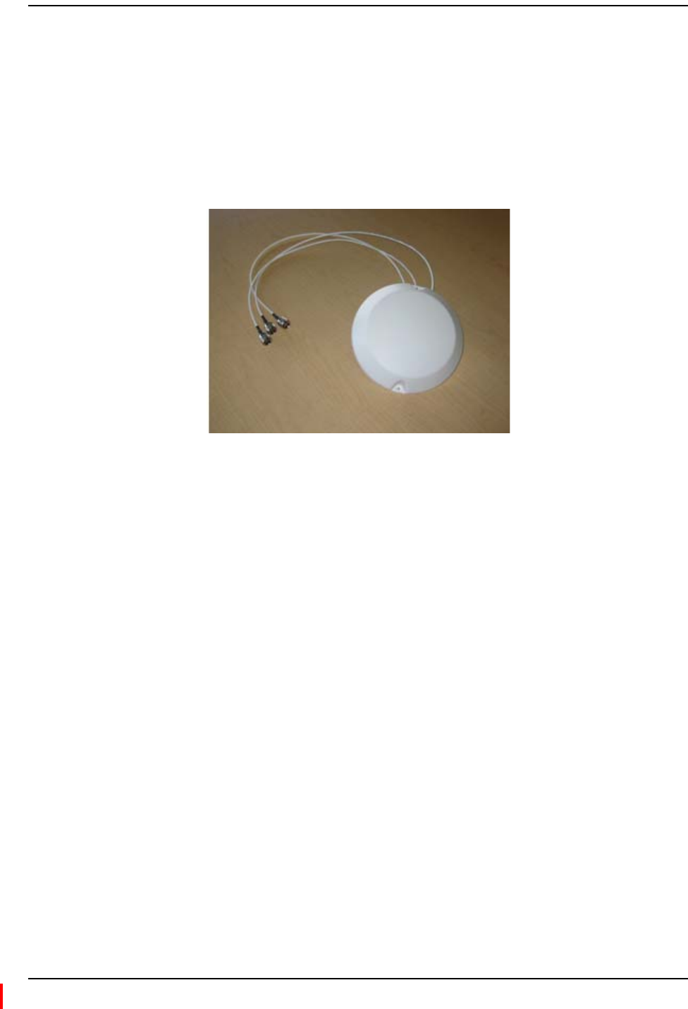
APPENDIXC:OMNIANTENNA
TheOmniAntenna(4214‐M727),showninFigure3,isaroundradomewiththefollowing
specifications:
•8.5‐inchdiameter
•1.65‐inchheight
•72‐inchpigtailsthatareplenum‐ratedcableswithN(male)connectors
Figure3.Omni Antenna
NOTE: TwoantennasperRAUisrequiredforMIMOperformance.
TheOmniAntennasupportsthefollowing:
•Port1
–698‐806MHz(700UpperCLowerABC)
–1710‐2170MHz(AWS)
•Port2
–806‐941MHz(Cellular/SMR)
–1850‐1990MHz(PCS)
•Port3
– 2500-2700 MHz (WiMAX)
Belden 7732A Coax Specifications
InterReach Spectrum Remote Access Unit Installation Guide - Preliminary Update for Issue 3 Page 25
ADCP-77-168 • Issue 3 • December 2011 © 2012 TE Connectivity Ltd.
APPENDIXD:CONTACTINGTECONNECTIVITY
PHONE
U.S.A. or CANADA
Sales: 1-800-366-3891
Extension 73000
Technical Assistance: 1-800-530-9960
Connectivity Extension: 73475
Wireless Extension: 73476
EUROPE
Sales Administration: +32-2-712-65 00
Technical Assistance: +32-2-712-65 42
EUROPEAN TOLL FREE NUMBERS
Germany: 0180 2232923
UK: 0800 960236
Spain: 900 983291
France: 0800 914032
Italy: 0800 782374
ASIA/PACIFIC
Sales Administration: +65-6294-9948
Technical Assistance: +65-6393-0739
ELSEWHERE
Sales Administration: +1-952-917-3000
Technical Assistance: +1-952-917-3475
EMAIL
ONLINE ACCESS
Connectivity Products
United States: Connectivity.Tac@te.com
Europe: Euro.Tac@te.com
Asia/Pacific: AsiaPacific.Tac@te.com
All Wireless Products
WirelessSupport@te.com
Customer Portal
http://www.adc.com/Americas/en_US/1268116693520
Online Customer Support Request
https://nssales.adc.com/ftr/ftrhome1.asp

Appendix D: Contacting TE Connectivity
Page 26 InterReach Spectrum Remote Access Unit Installation Guide - Preliminary Update for Issue 3
© 2012 TE Connectivity Ltd ADCP-77-168 • Issue 3 • December 2011