ADC Telecommunications UNS-819RAU-1 In-Building RF Distribution System User Manual
ADC Telecommunications Inc. In-Building RF Distribution System
UserManual.wiki
>
ADC Telecommunications
>
UNS 819RAU 1 User Manual
User Manual
Navigation menu
Upload a User Manual
Namespaces
Wiki Guide
HTML
PDF
Info
Views
User Manual
Discussion / Help
Navigation


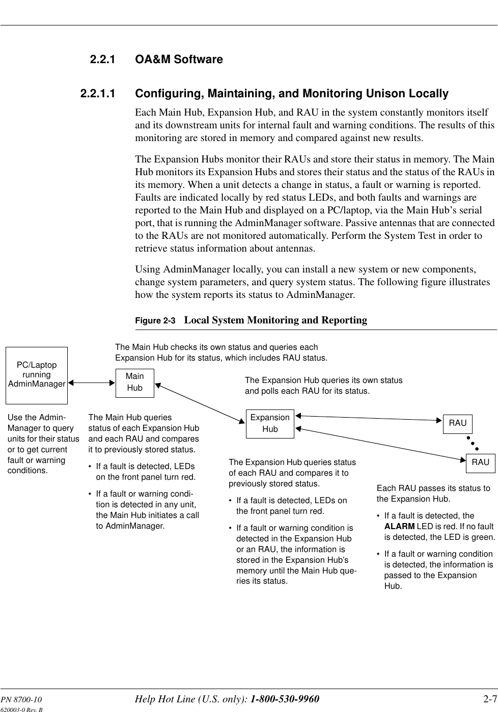
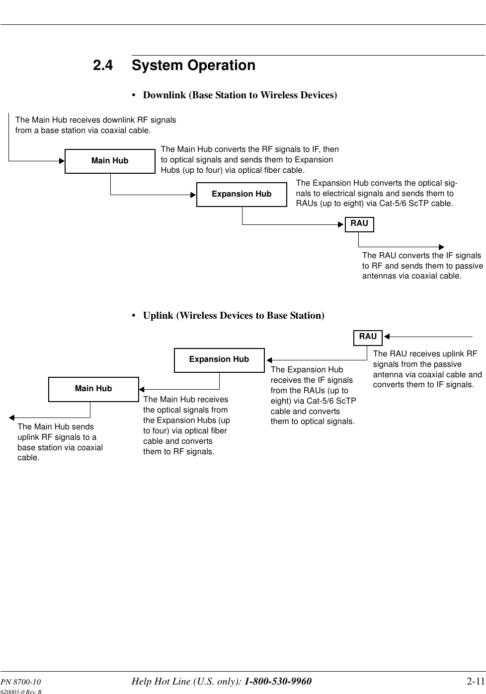
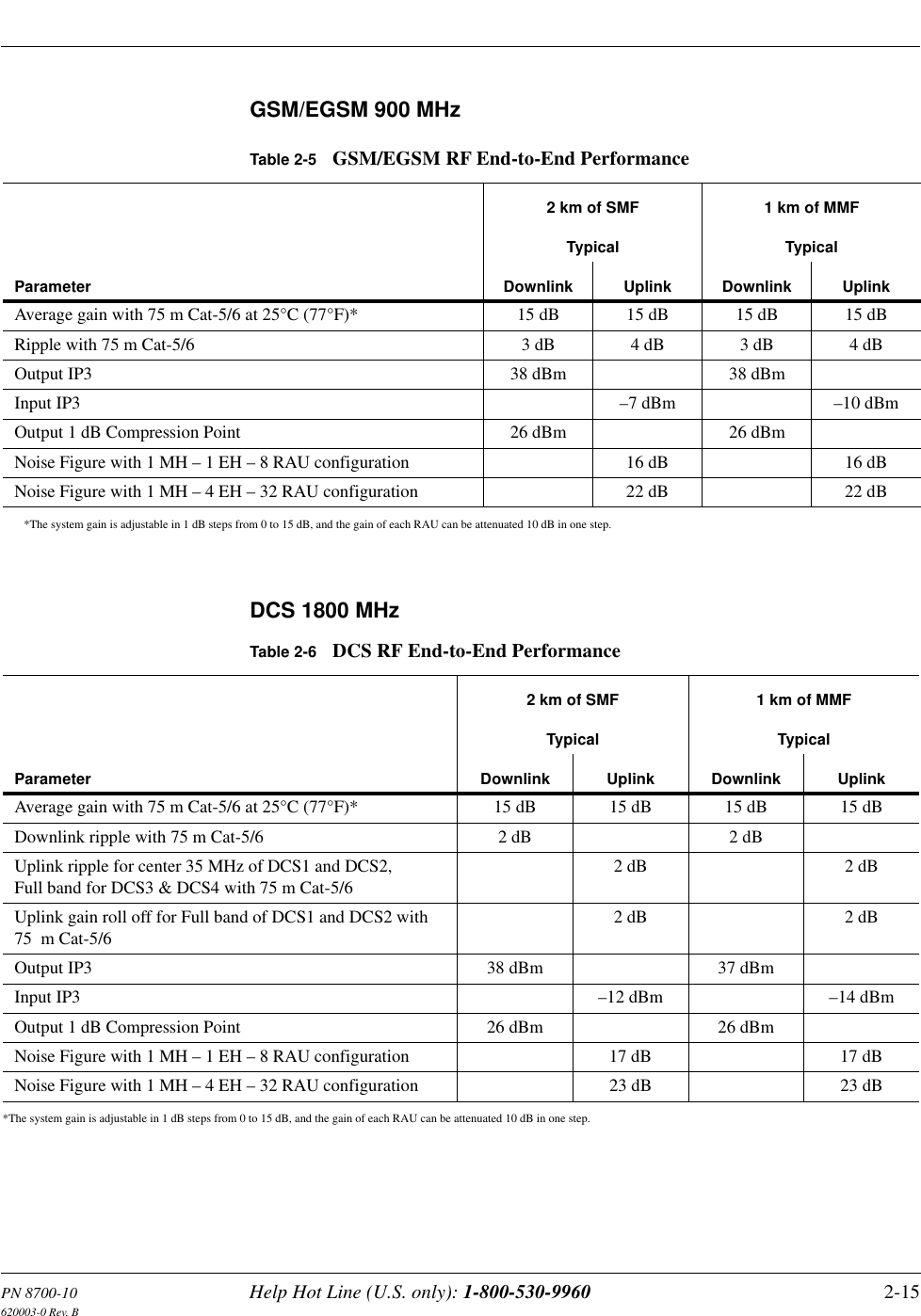
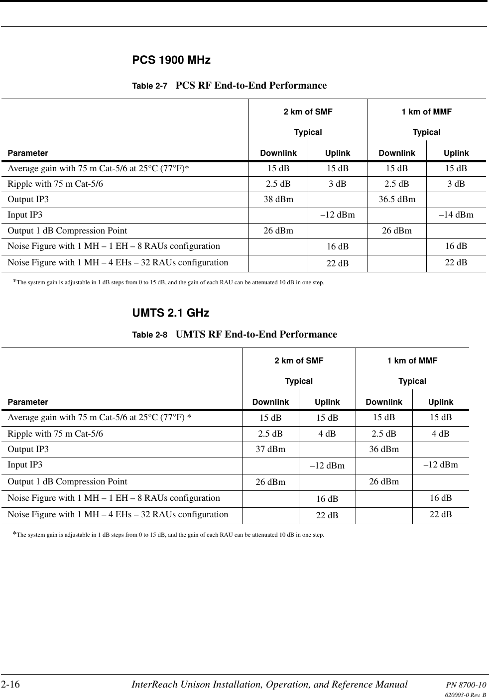
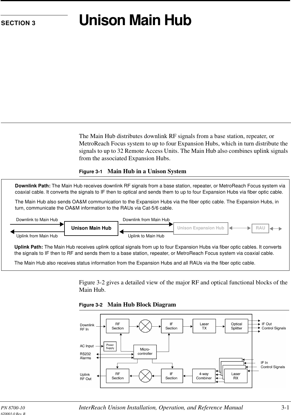
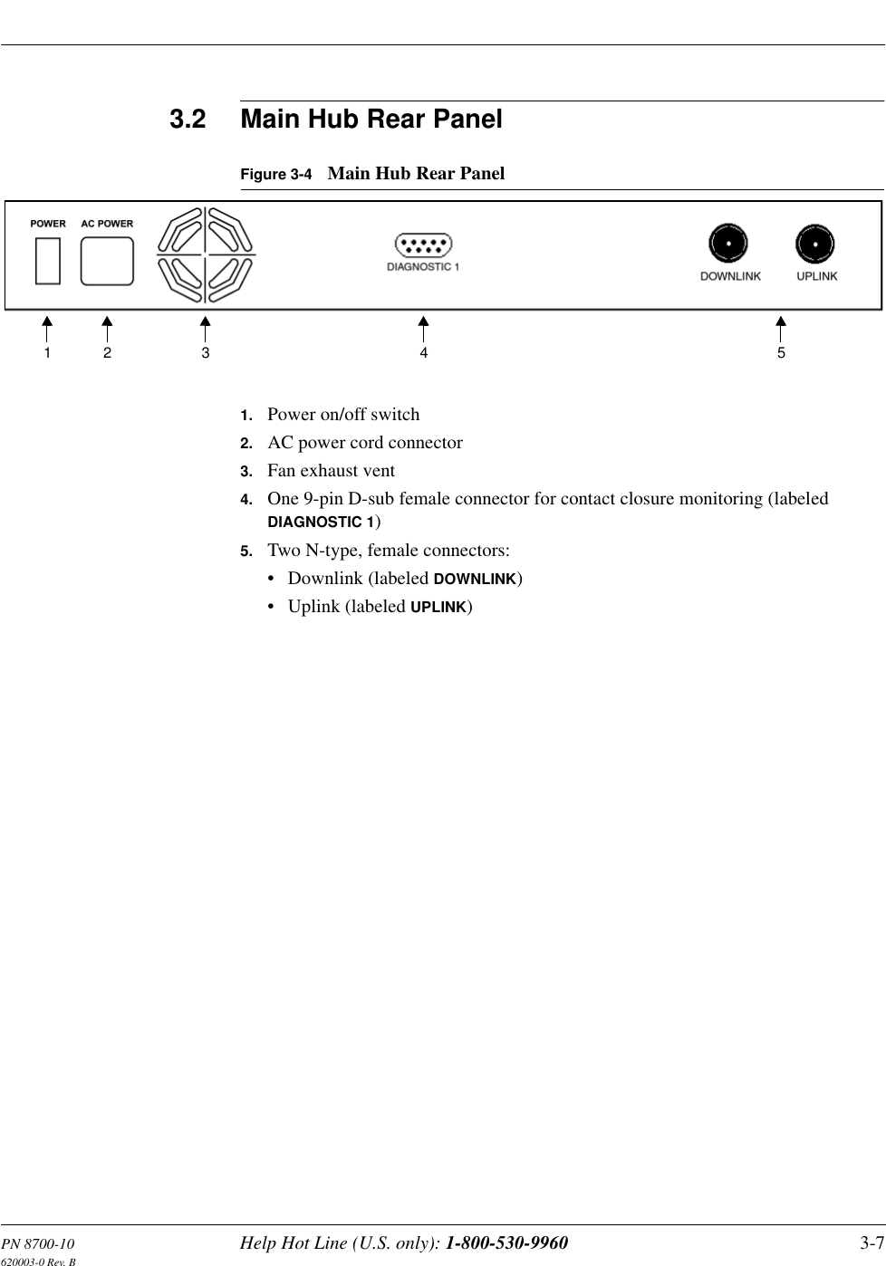
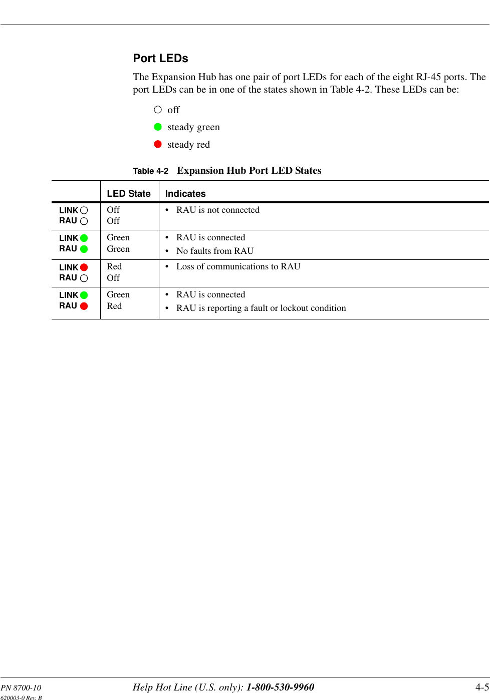
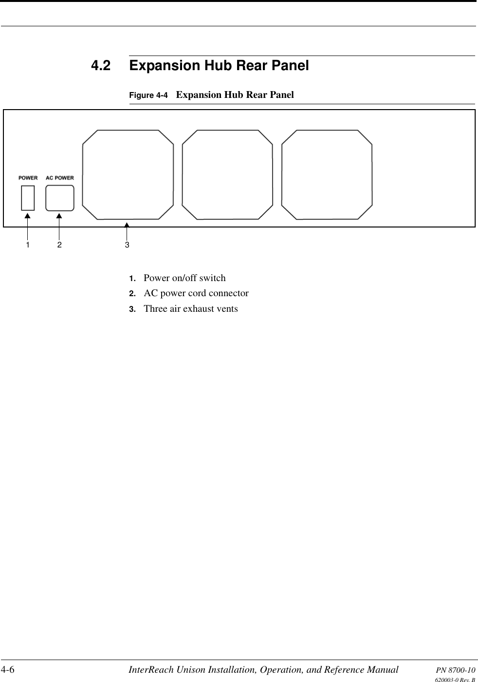
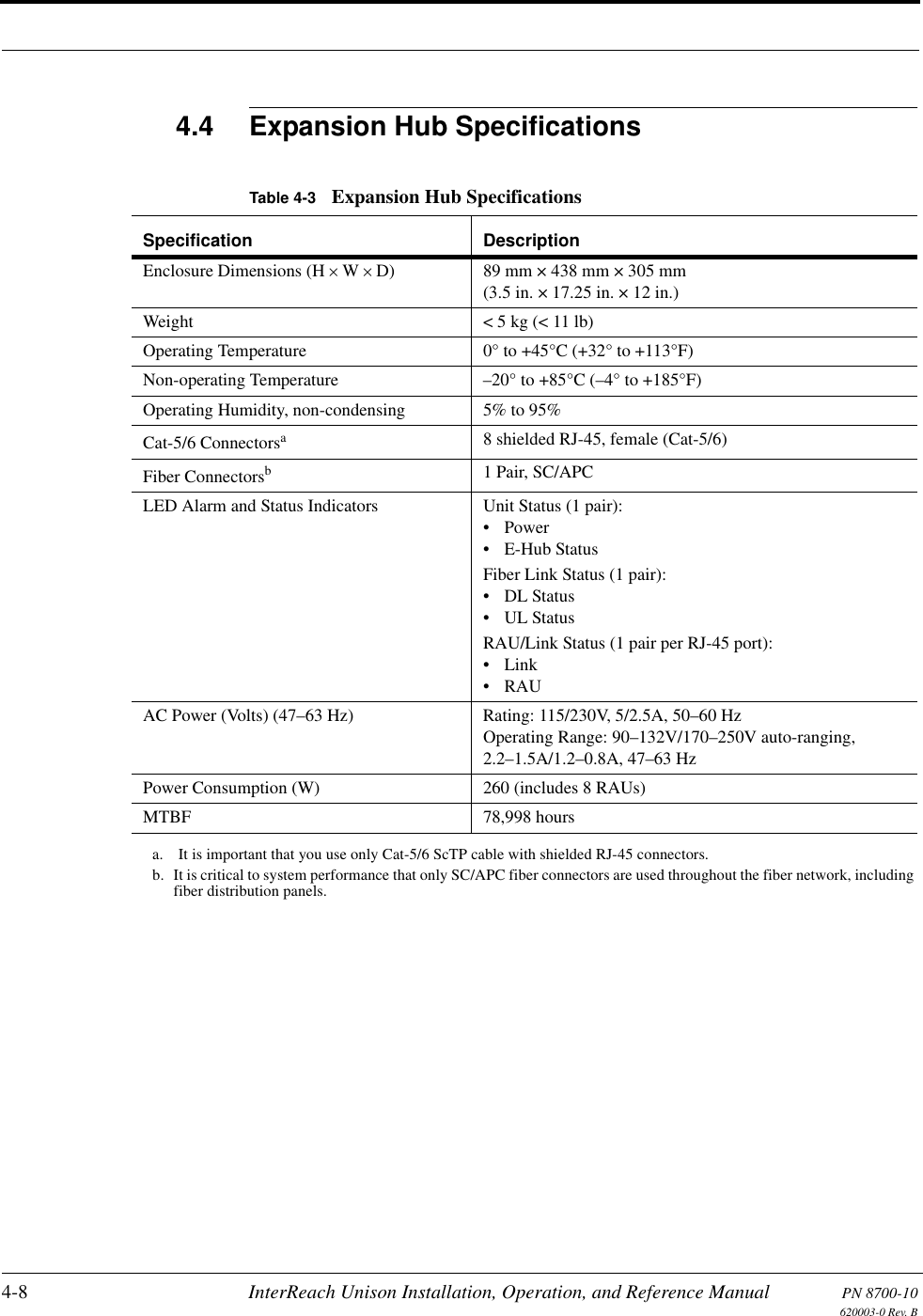
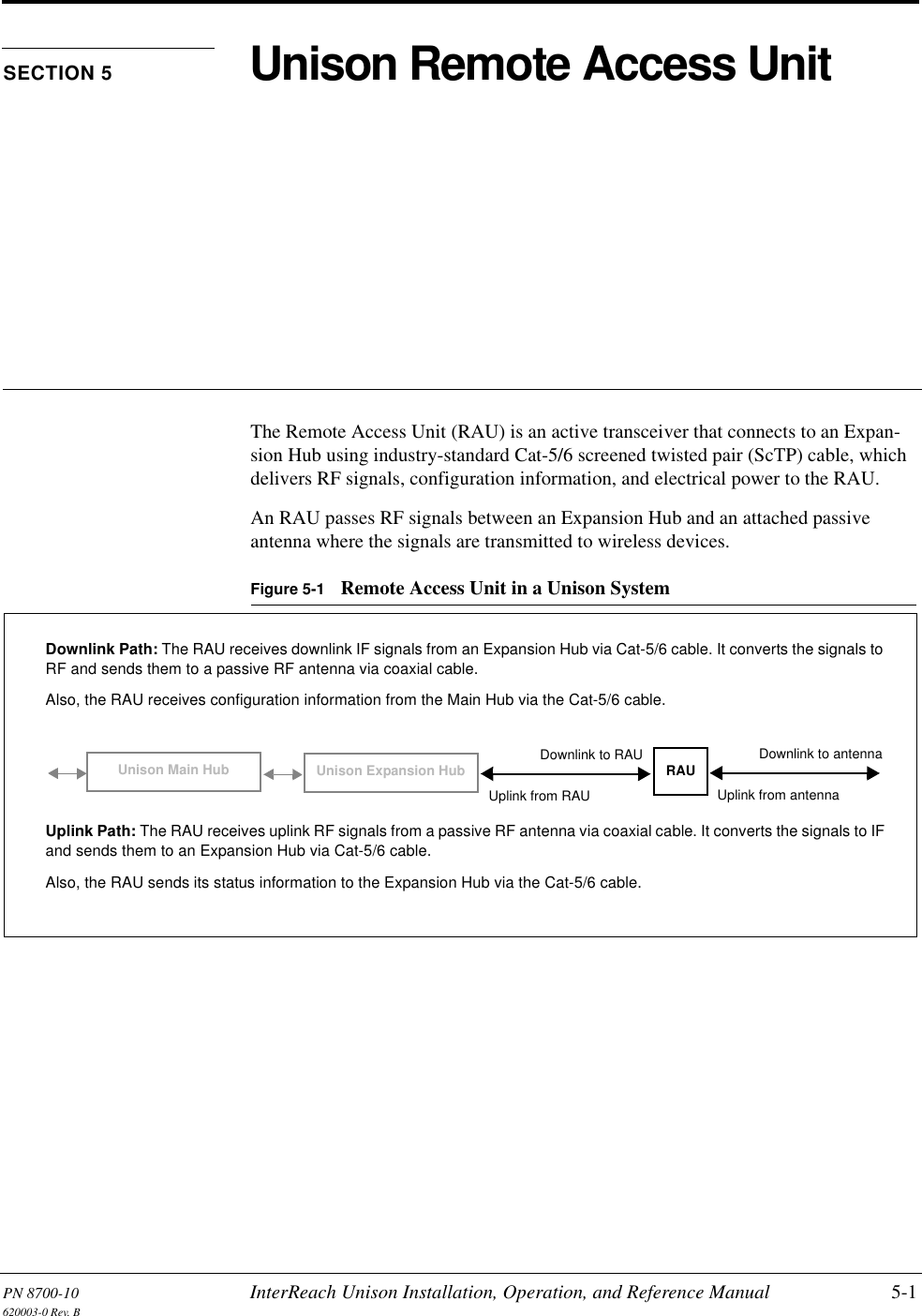
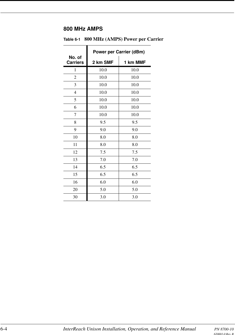
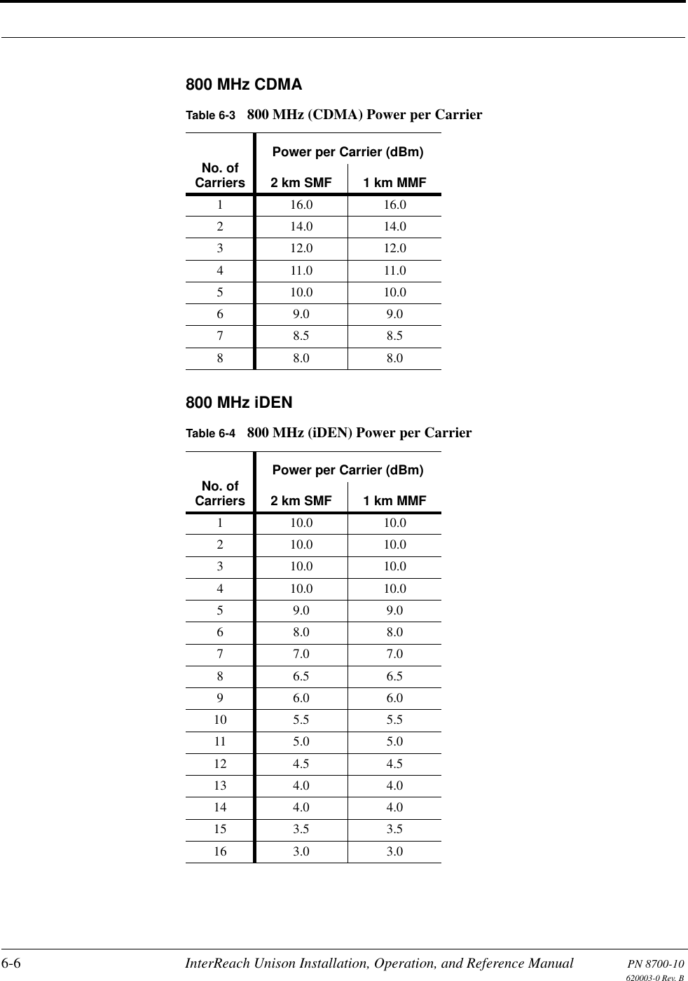
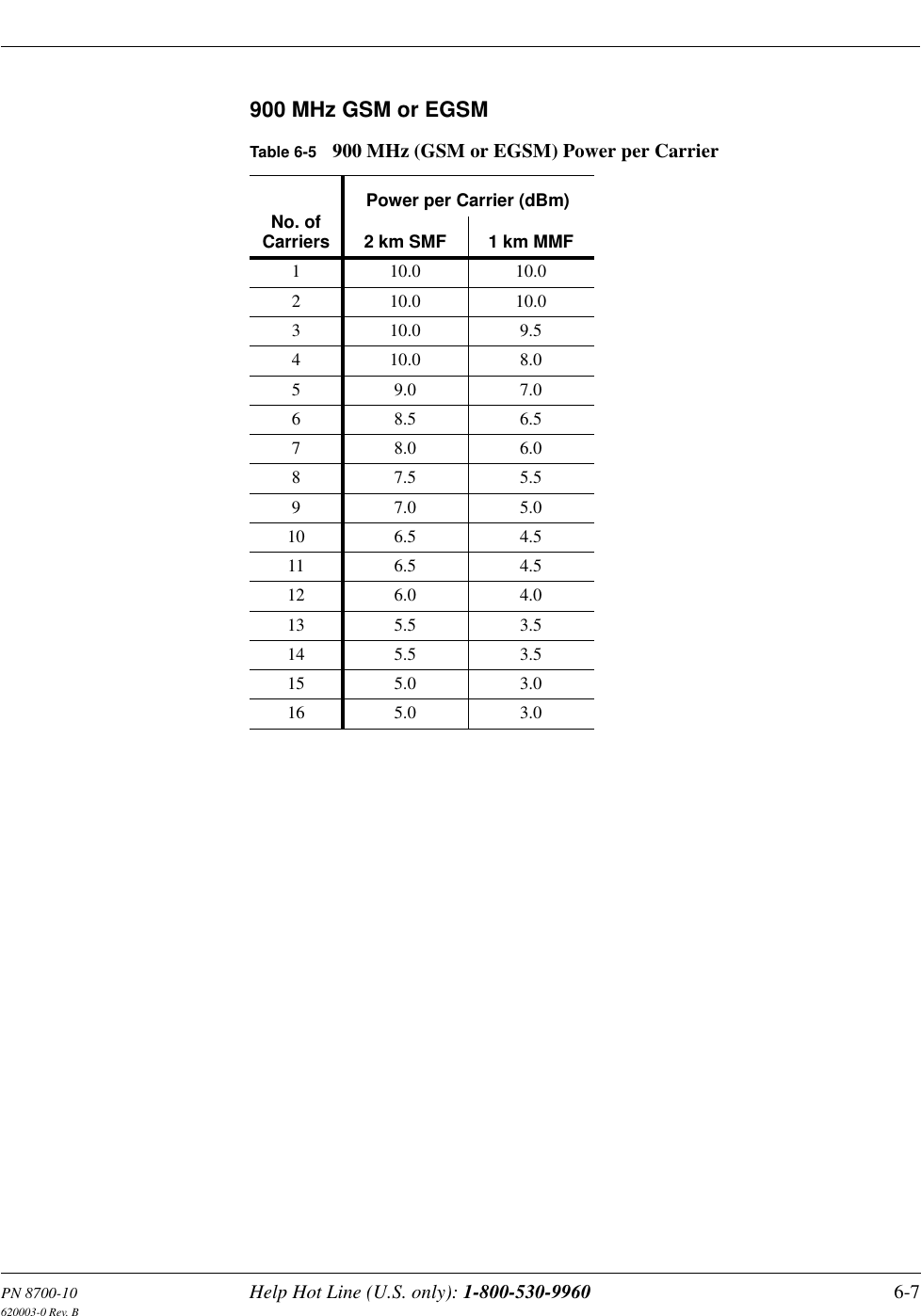
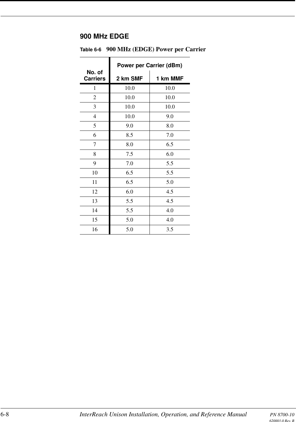
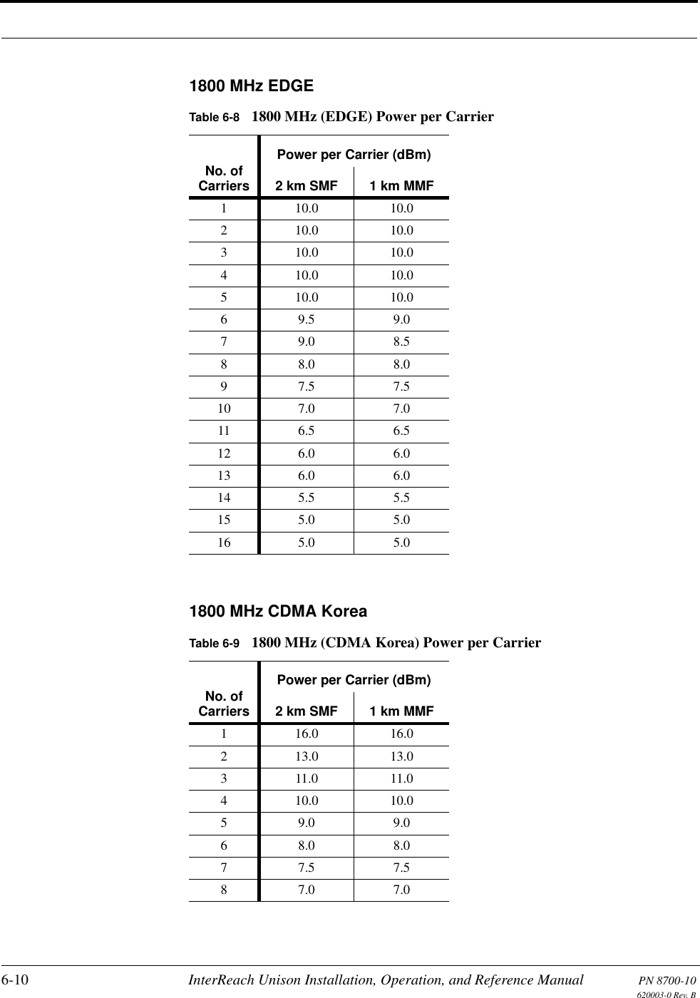
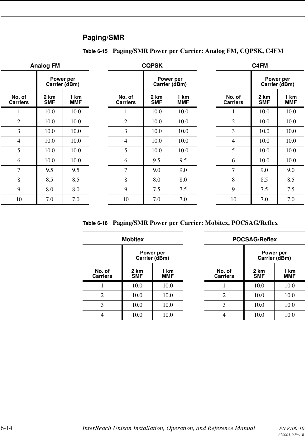
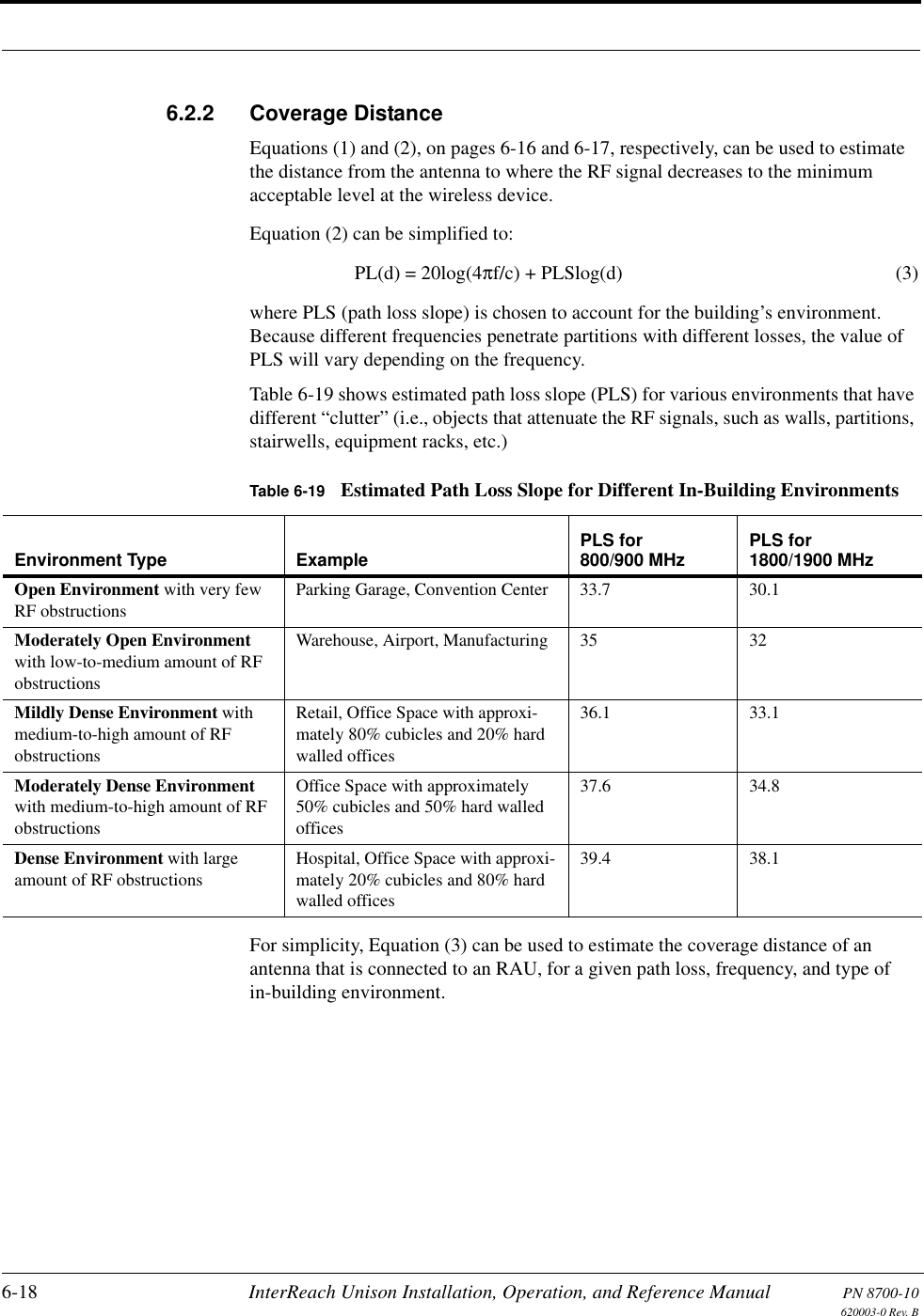
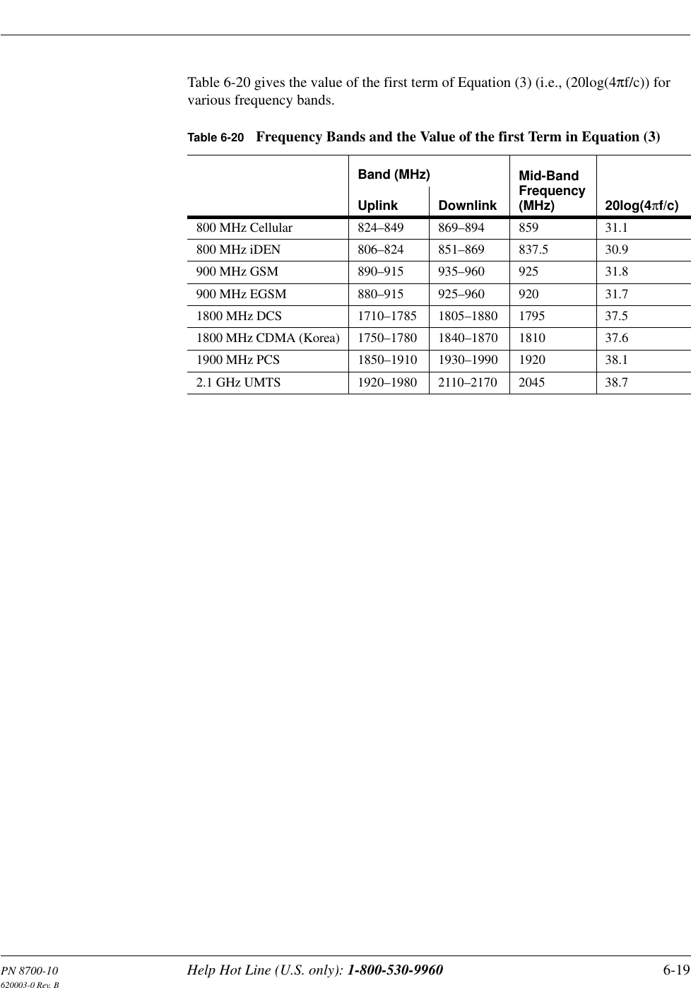
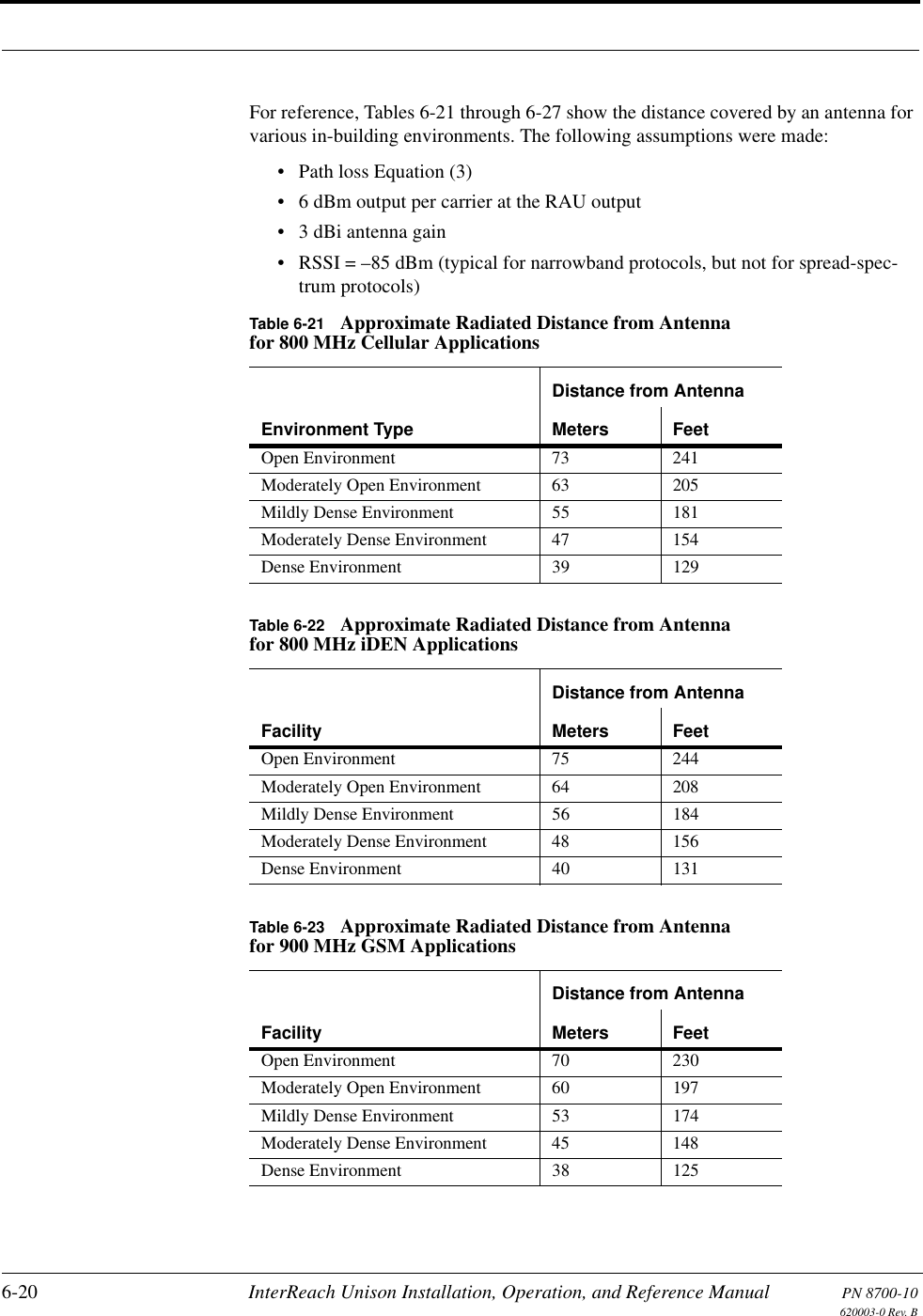
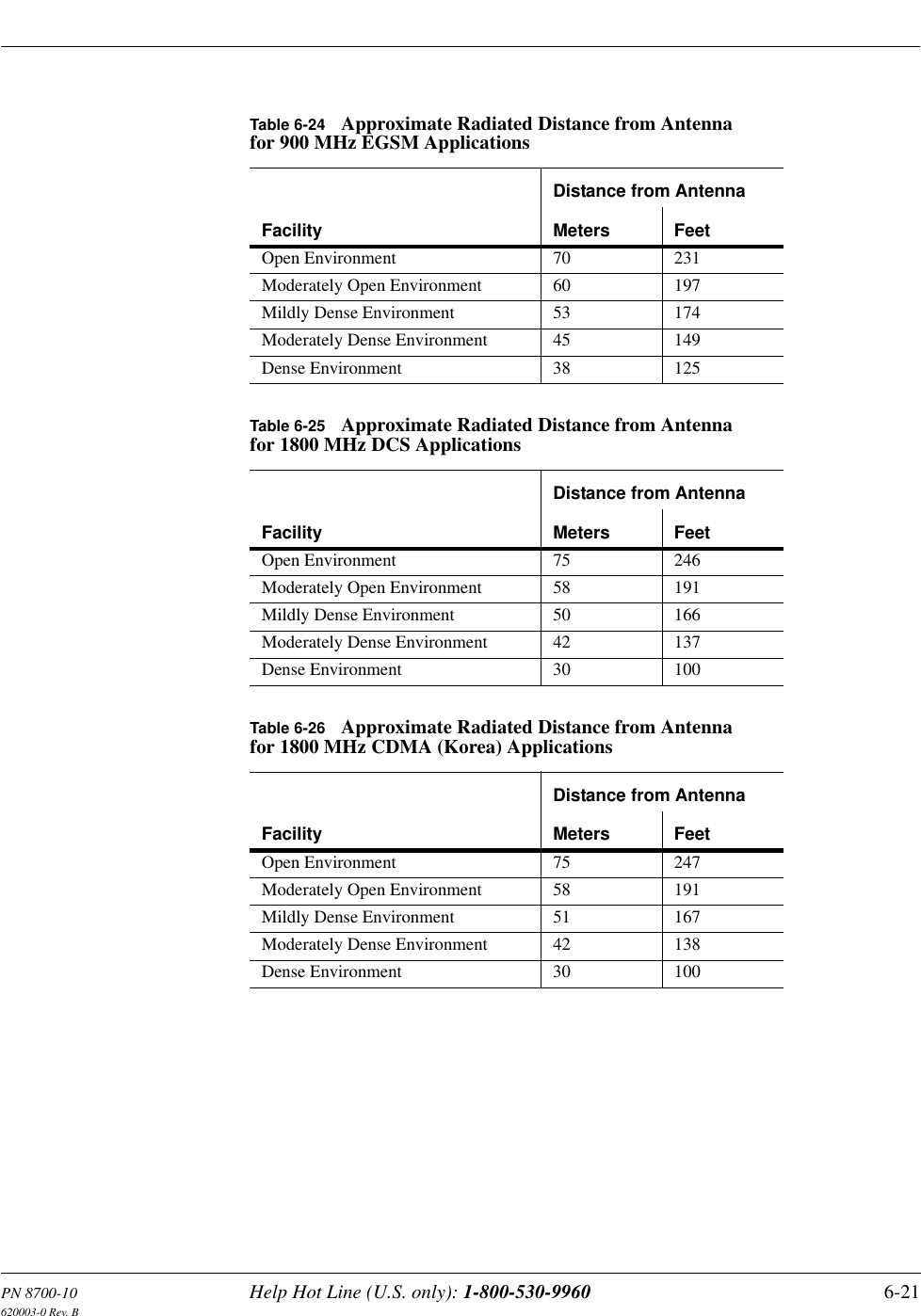
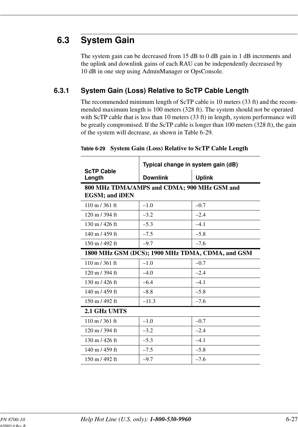
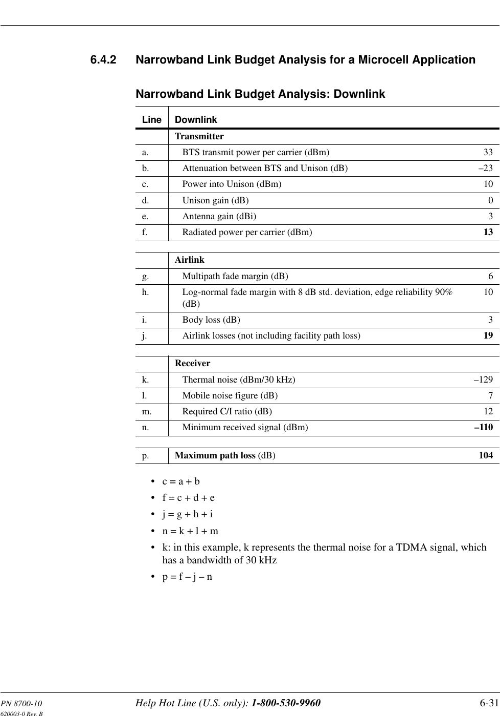
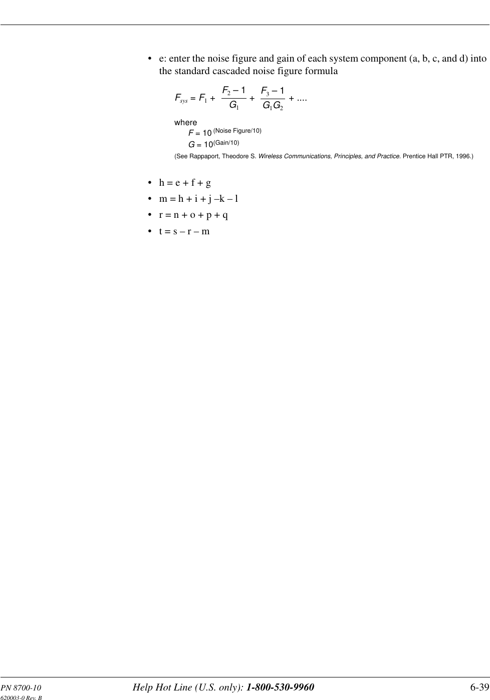
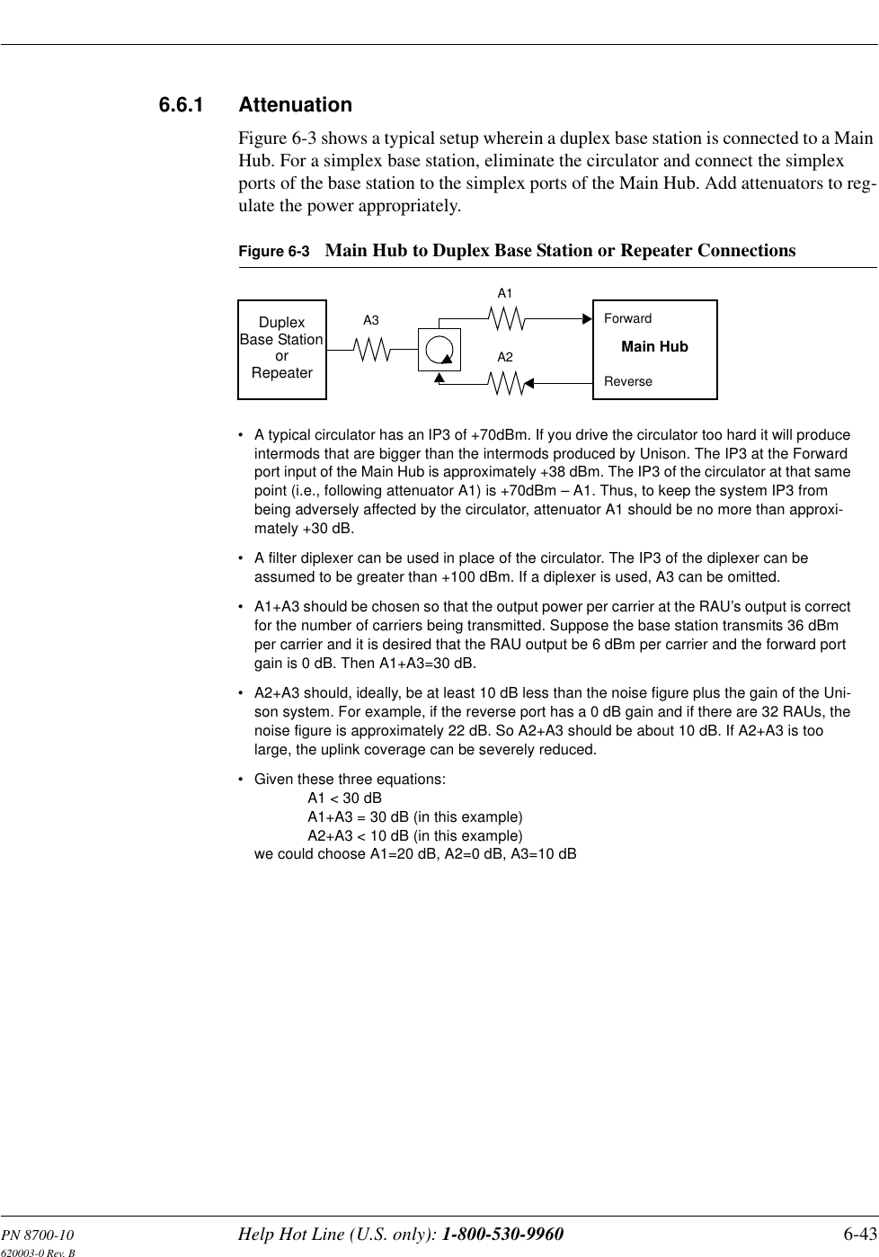
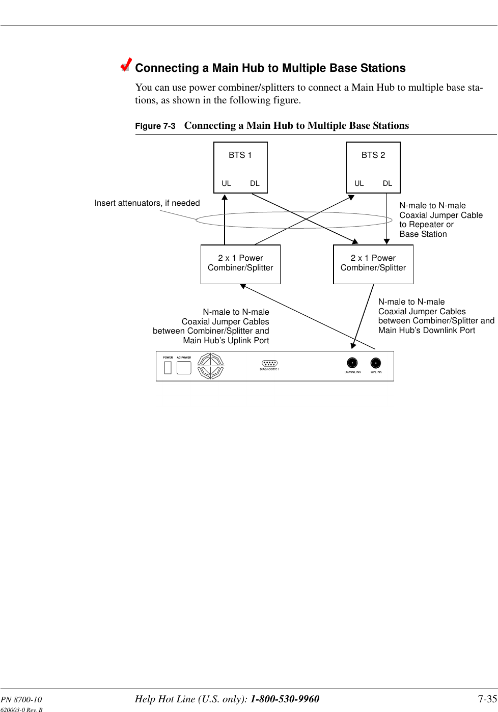
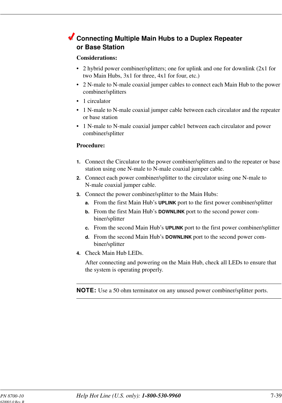
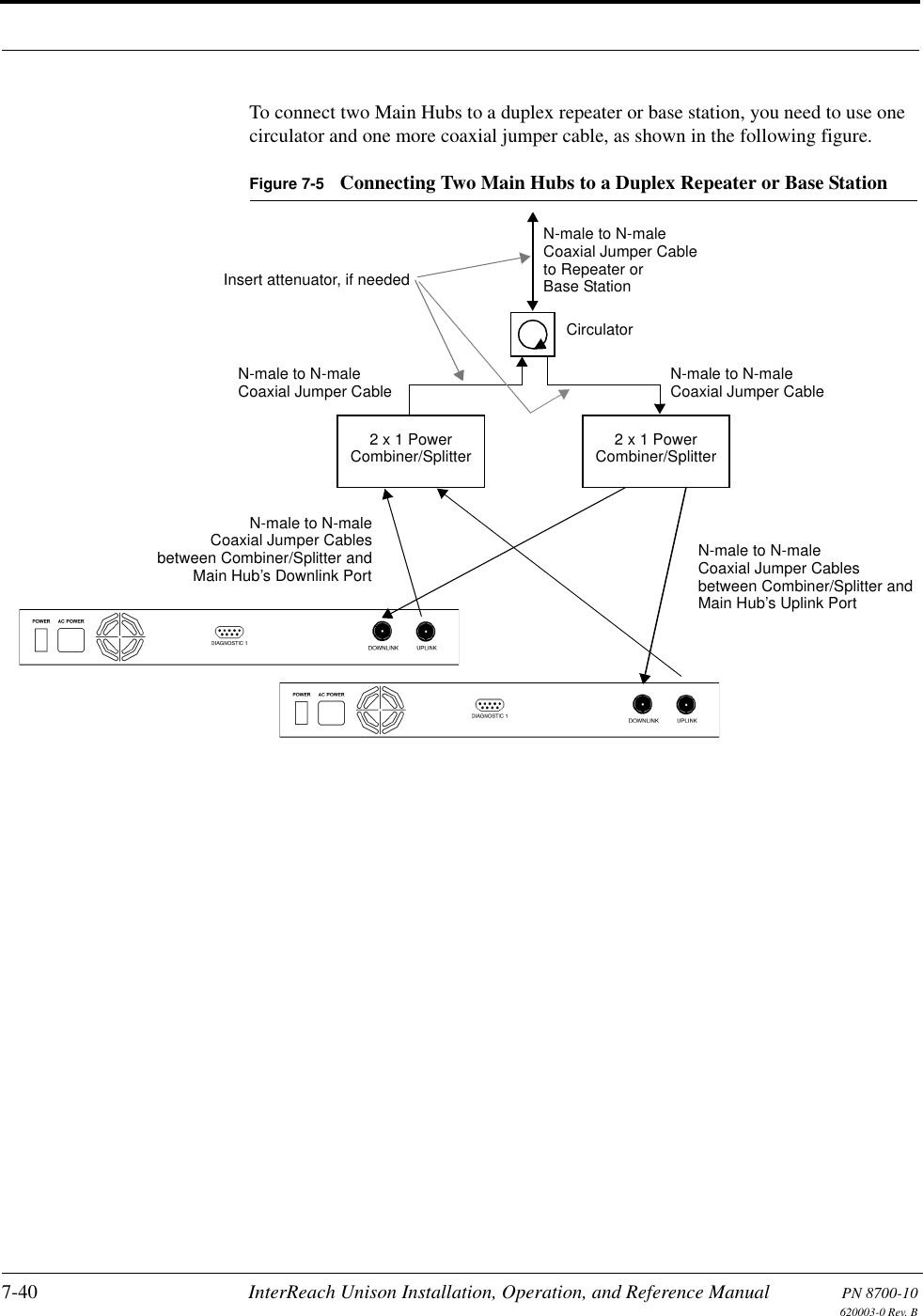
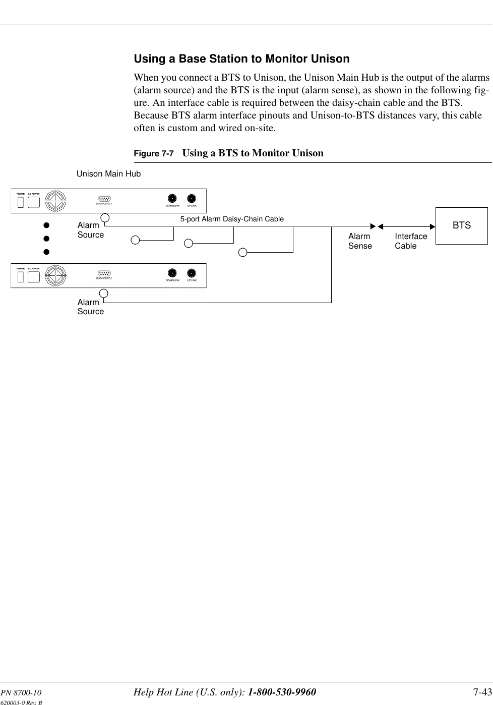
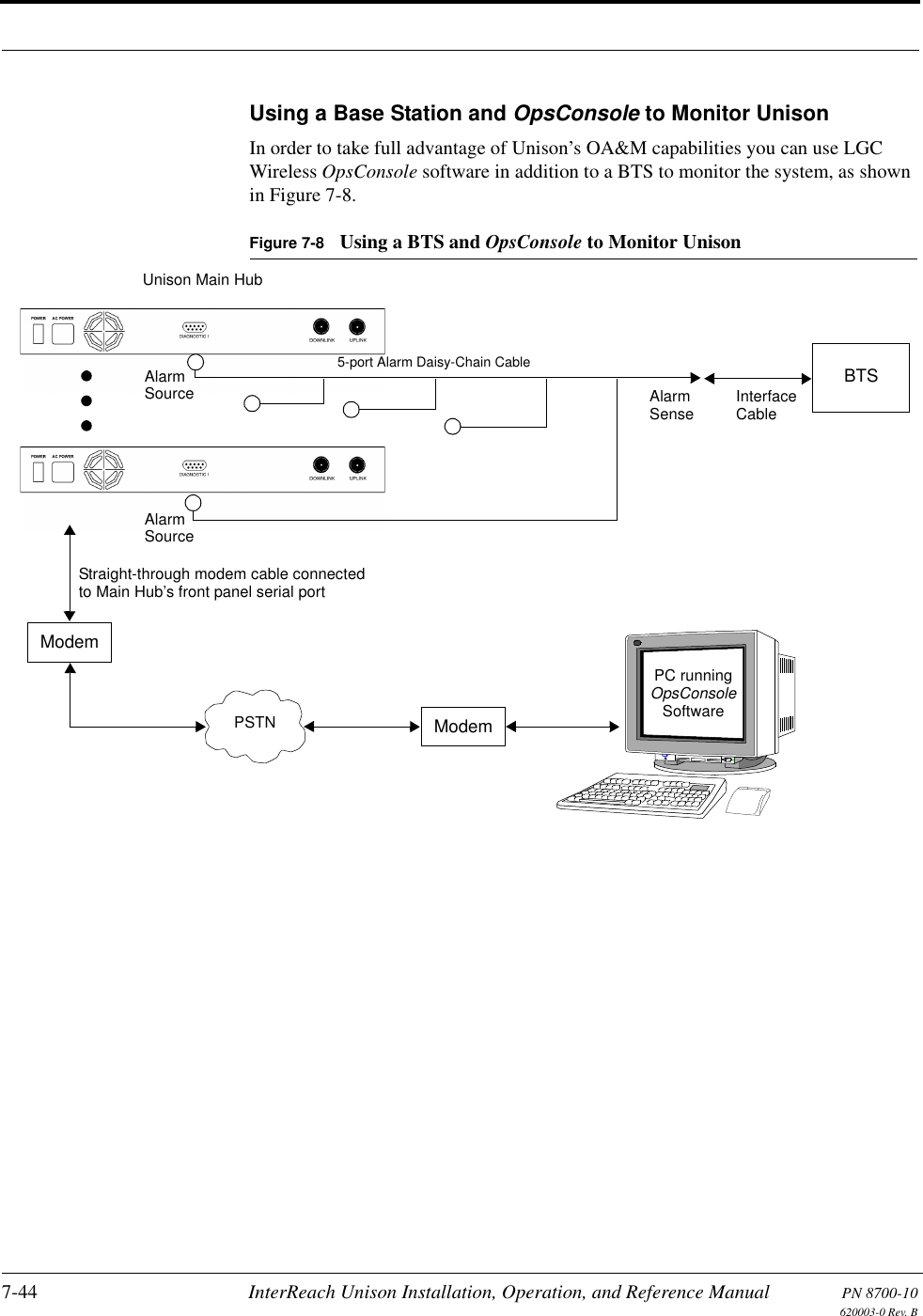
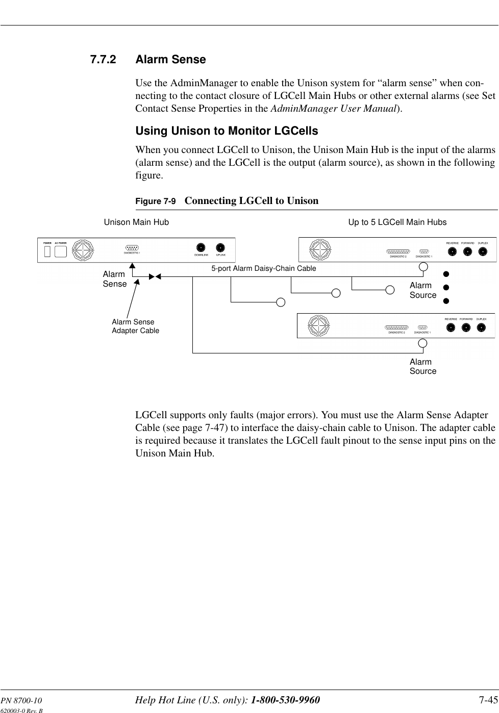
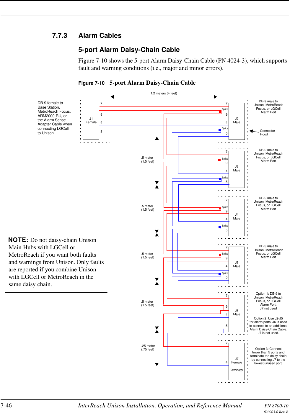
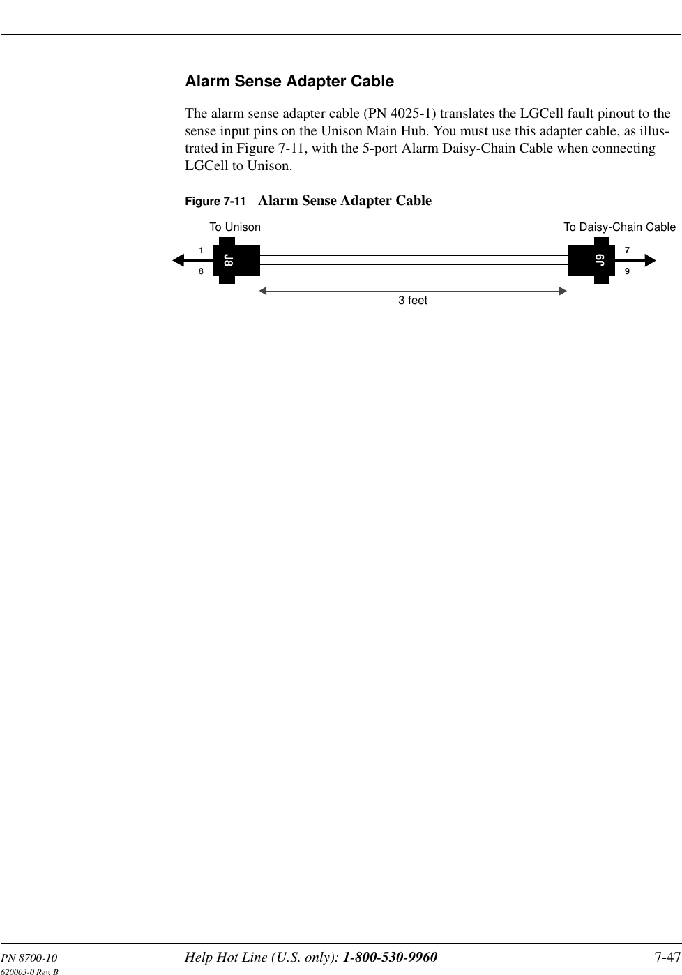
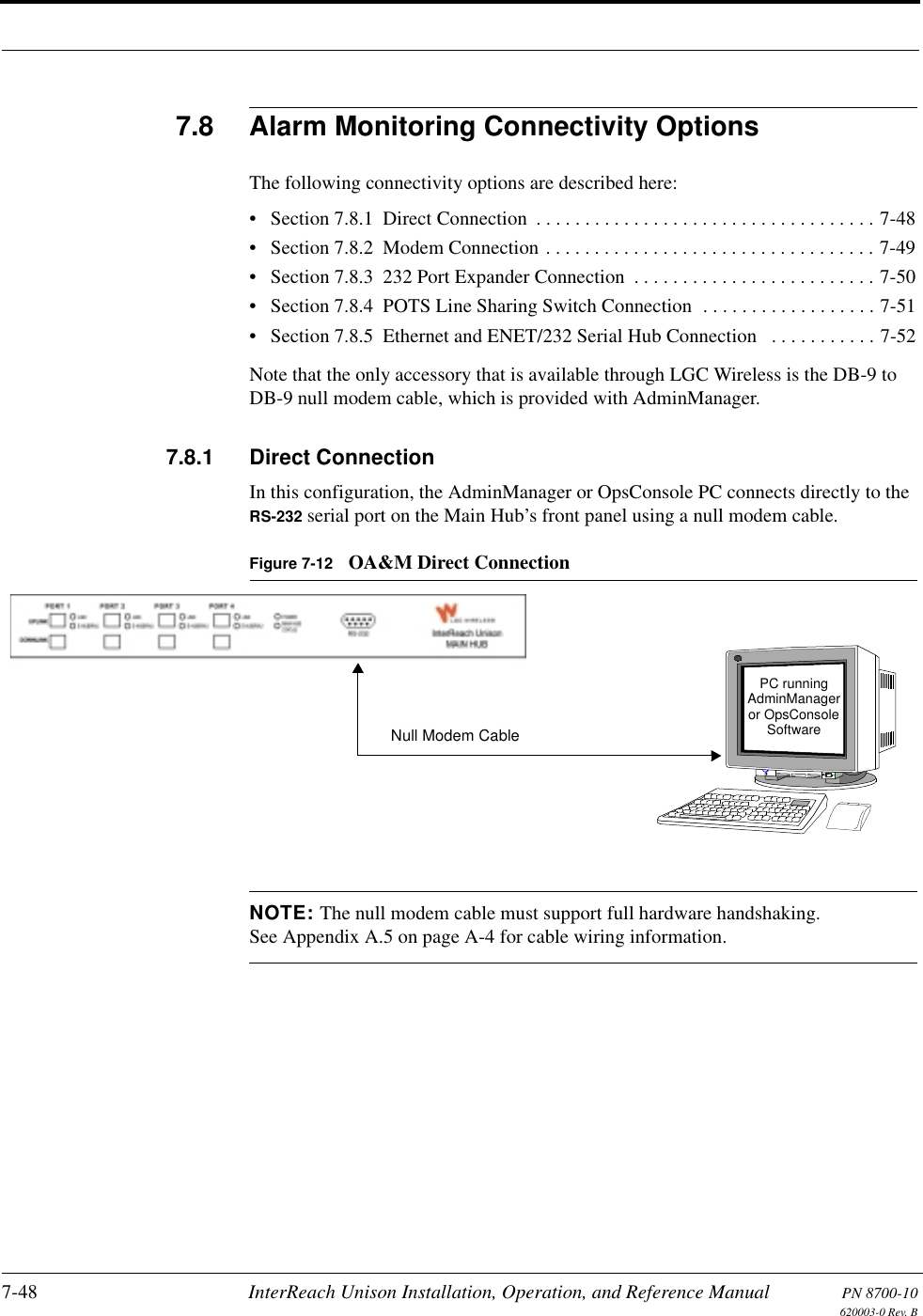
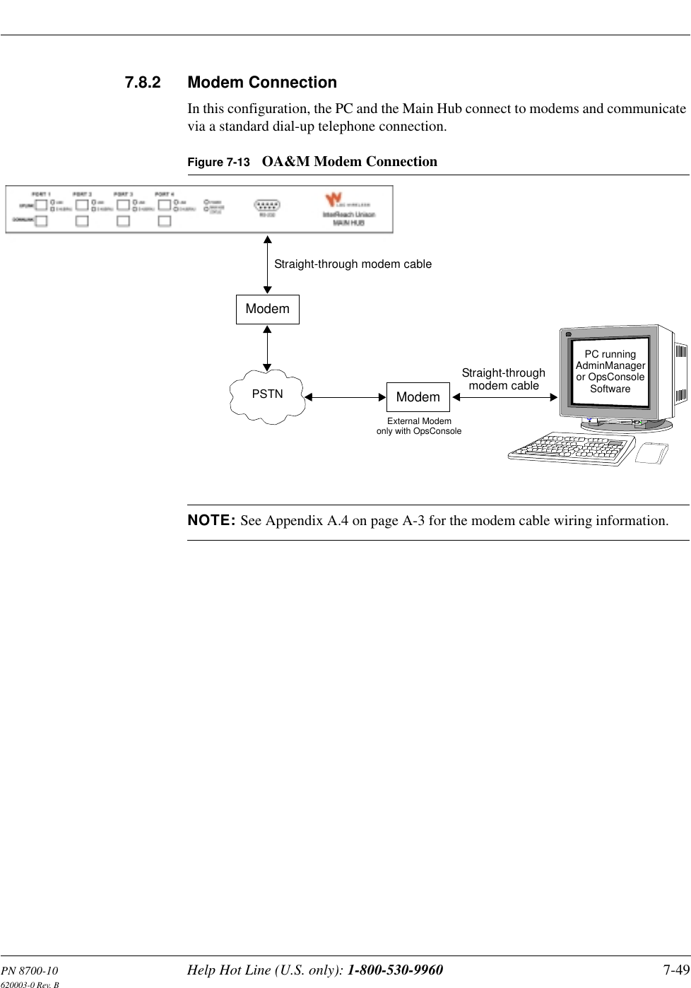
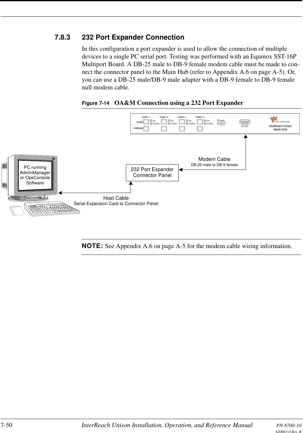
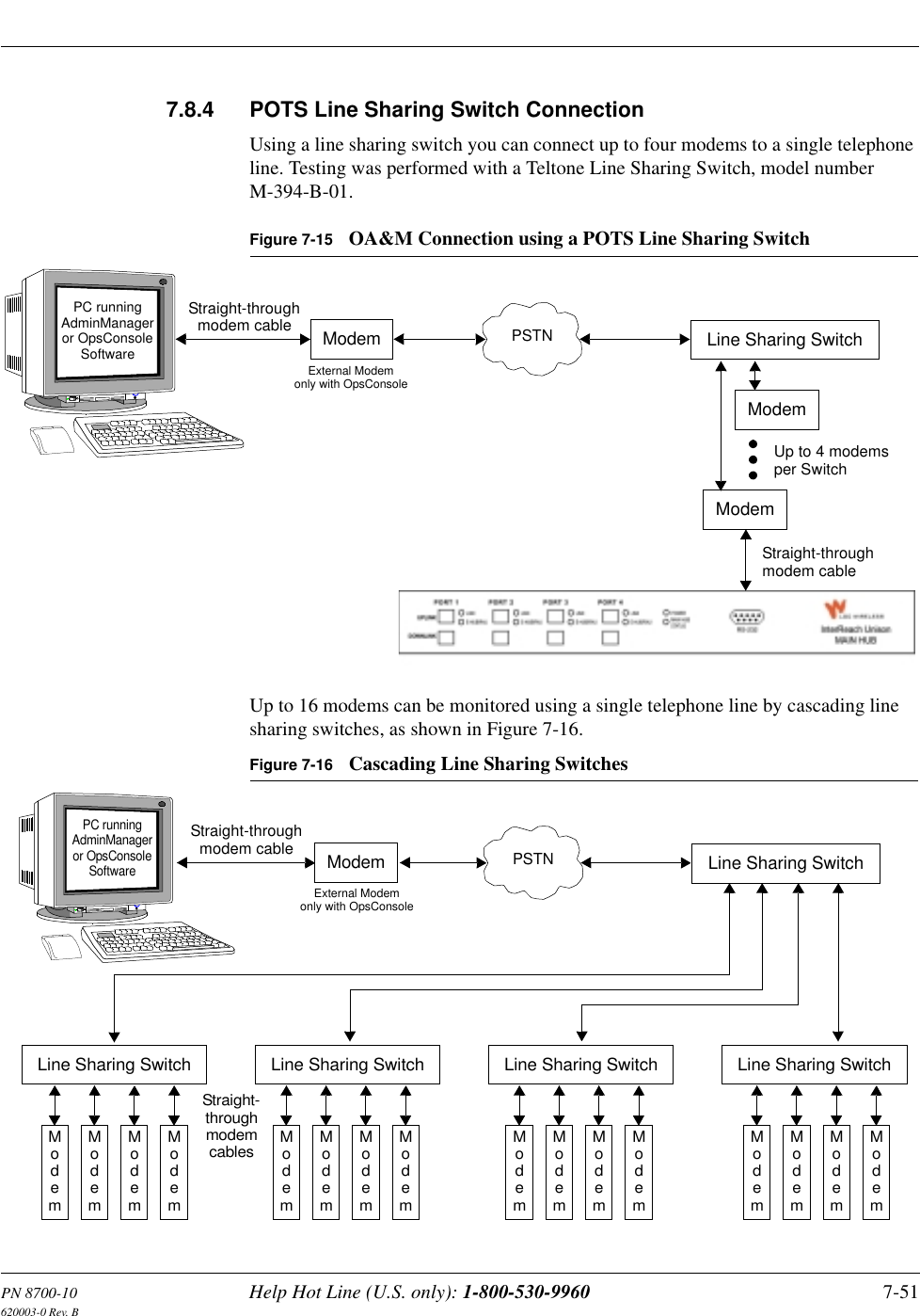
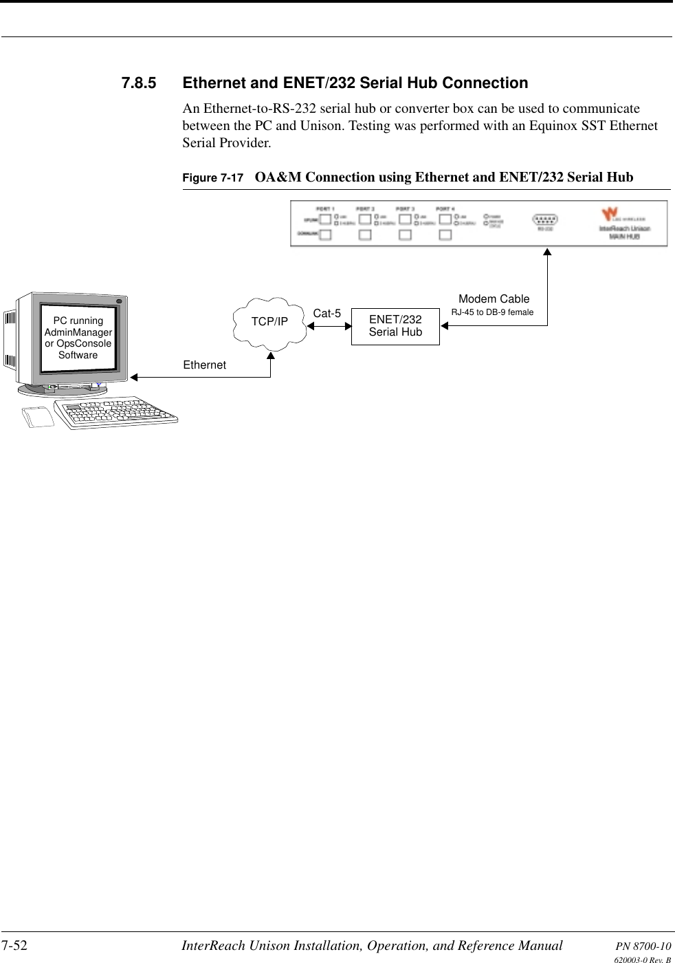
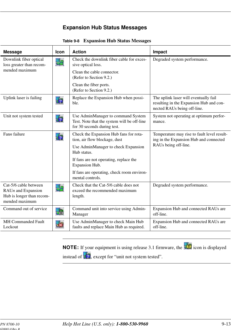
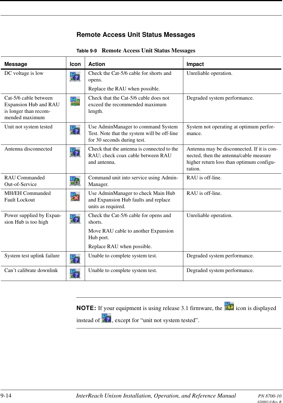
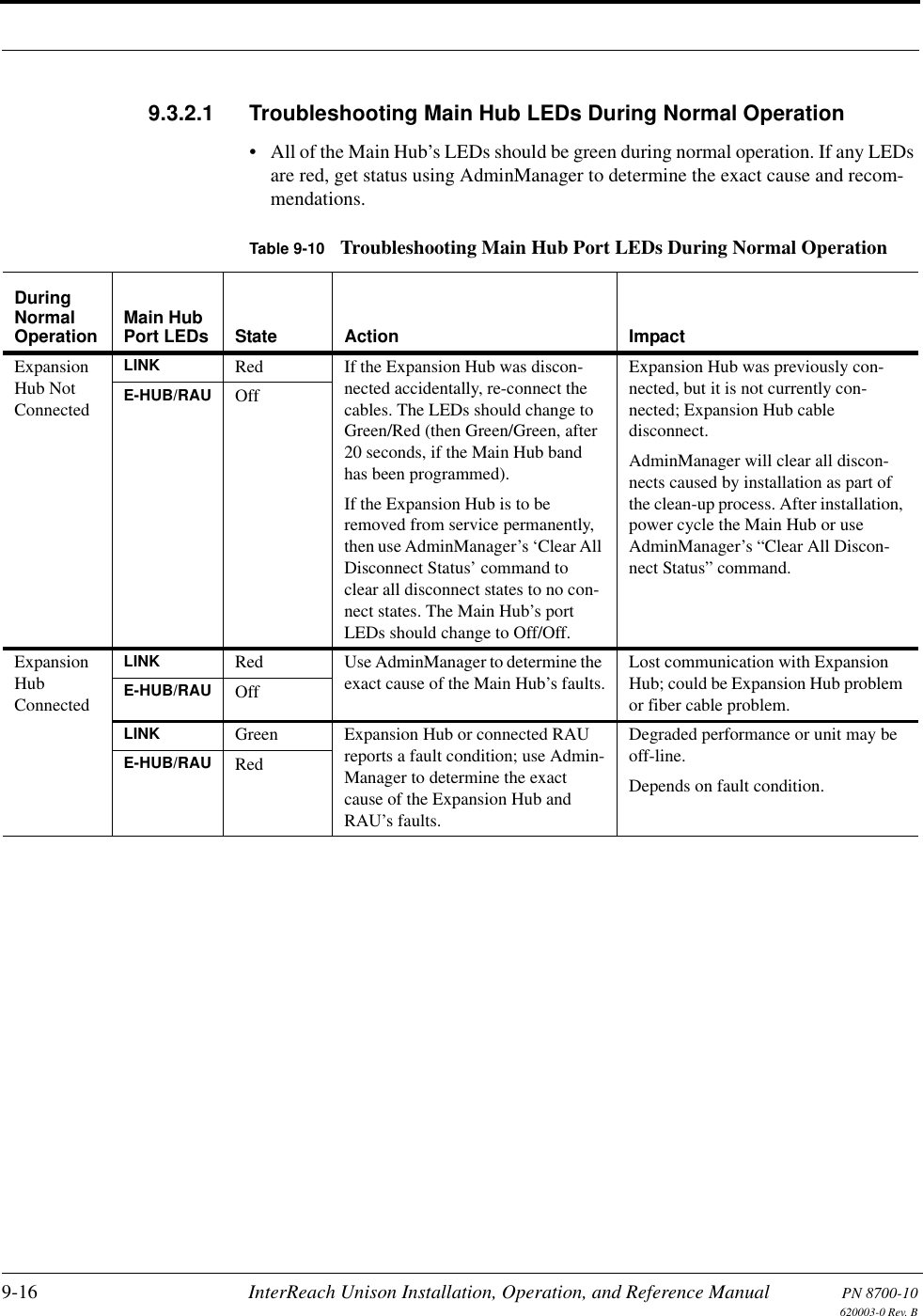
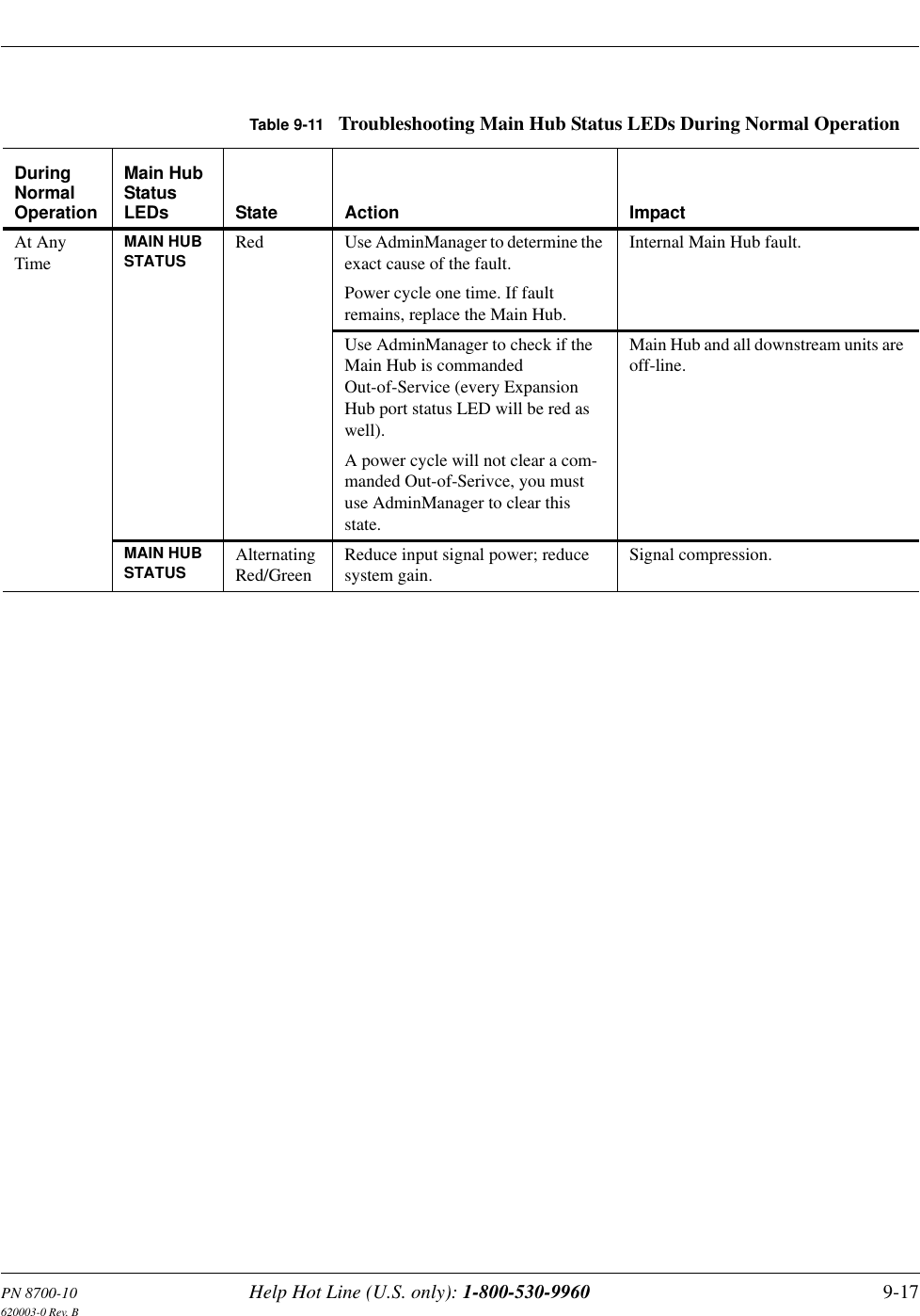
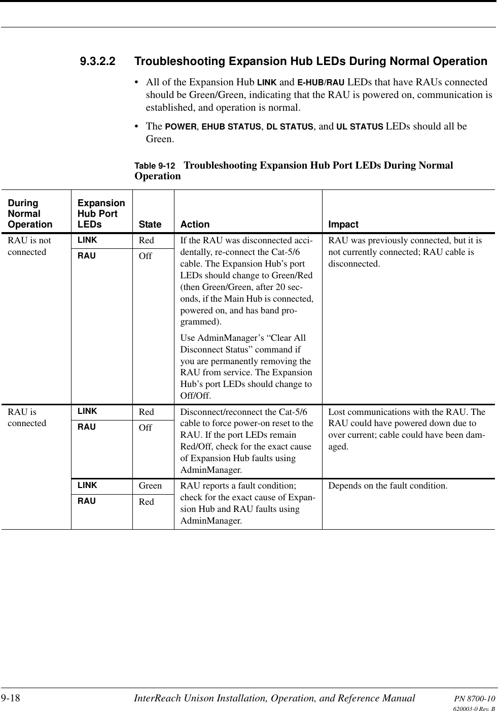
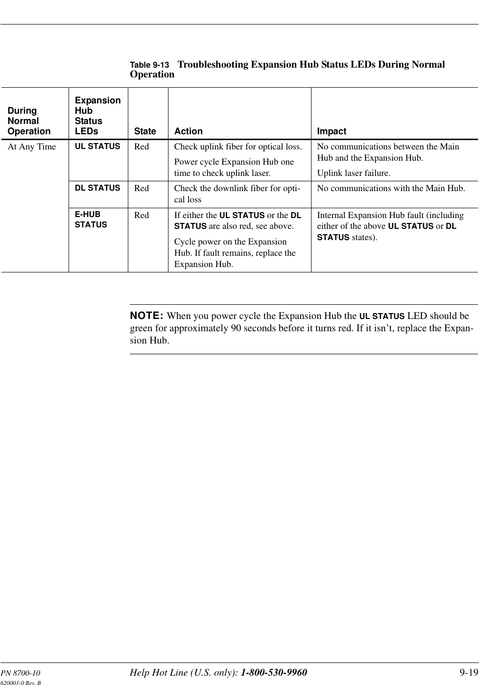
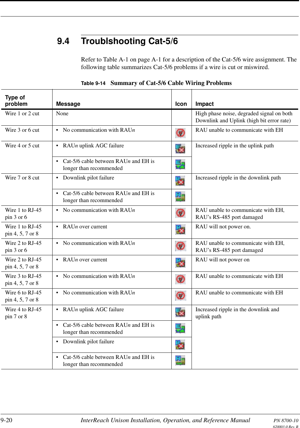
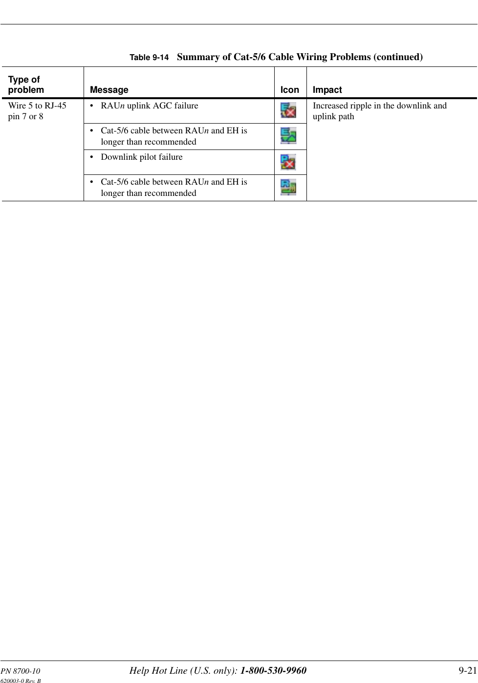
![2-2 InterReach Unison Installation, Operation, and Reference Manual PN 8700-10620003-0 Rev. BKey System Features•Superior RF performance, particularly in the areas of IP3 and noise figure.•High downlink composite power and low uplink noise figure enables support of a large number of channels and larger coverage footprint per antenna.•Software configurable Main and Expansion Hubs. Thus, the frequency band can be configured in the field.•Either single-mode or multi-mode fiber can be used, supporting flexible cabling alternatives (in addition to standard Cat-5 or Cat-6 [Cat-5/6] screened twisted pair [ScTP]). Cabling type can be selected to meet the resident cabling infrastructure of the facility and unique building topologies.•Extended system “reach.” Using single-mode fiber, fiber runs can be as long as 6 kilometers (creating a total system “wingspan” of 12 kilometers). Alternately, with multi-mode fiber, fiber runs can be as long as 1.5 kilometers. The Cat-5/6 ScTP cable run can be up to 100 meters recommended maximum (150 meters with RF performance degradation).•Flexible RF configuration capabilities, including:• System gain:– Ability to manually set gain in 1 dB steps, from 0 to 15 dB, on both down-link and uplink.• RAU:– RAU uplink and downlink gain can be independently attenuated 10 dB.– Uplink level control protects the system from input overload and can be optimized for either a single operator or multiple operators/protocols.– VSWR check on RAU reports if there is a disconnected antenna (all RAUs except UMTS).•Firmware Updates are downloaded (either locally or remotely) to operating sys-tems when any modifications are made to the product, including the addition of new software capabilities/services.•Extensive OA&M capabilities, including fault isolation to the field replaceable unit, automatic reporting of all fault and warning conditions, and user-friendly graphical-user interface OA&M software packages.](https://usermanual.wiki/ADC-Telecommunications/UNS-819RAU-1/User-Guide-267191-Page-24.png)