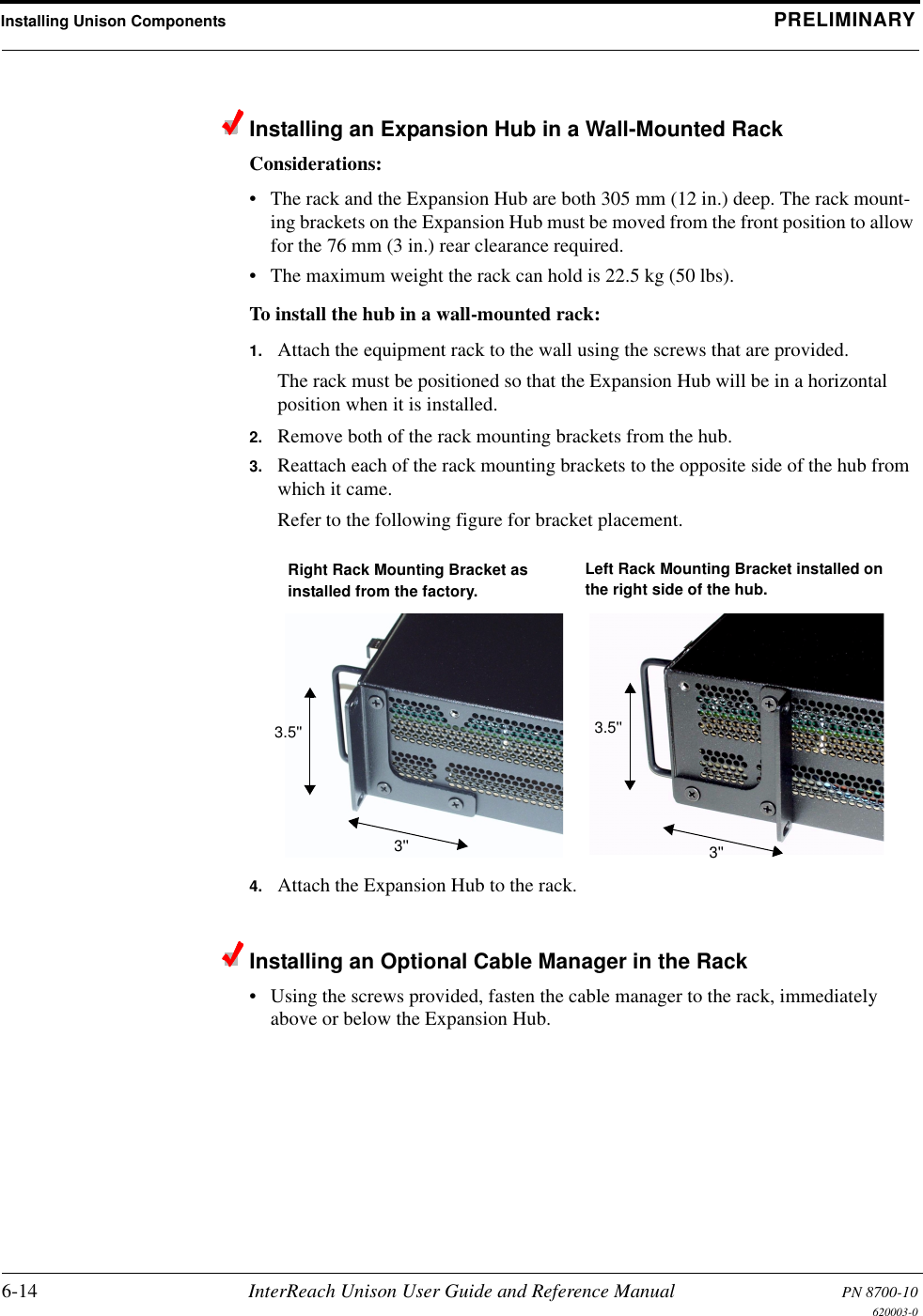
ADC Telecommunications UNS-EGSM-1 InterReach Unison EGSM User Manual unison
ADC Telecommunications Inc. InterReach Unison EGSM unison
UserManual.wiki
>
ADC Telecommunications
>
UNS EGSM 1 User Manual
User manual
Navigation menu
Upload a User Manual
Namespaces
Wiki Guide
HTML
PDF
Info
Views
User Manual
Discussion / Help
Navigation


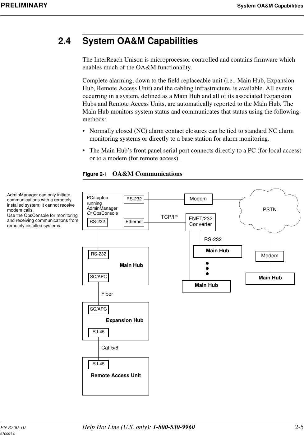
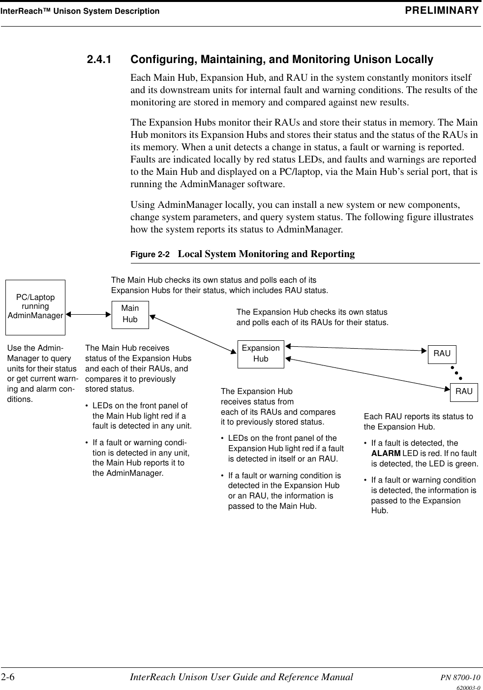
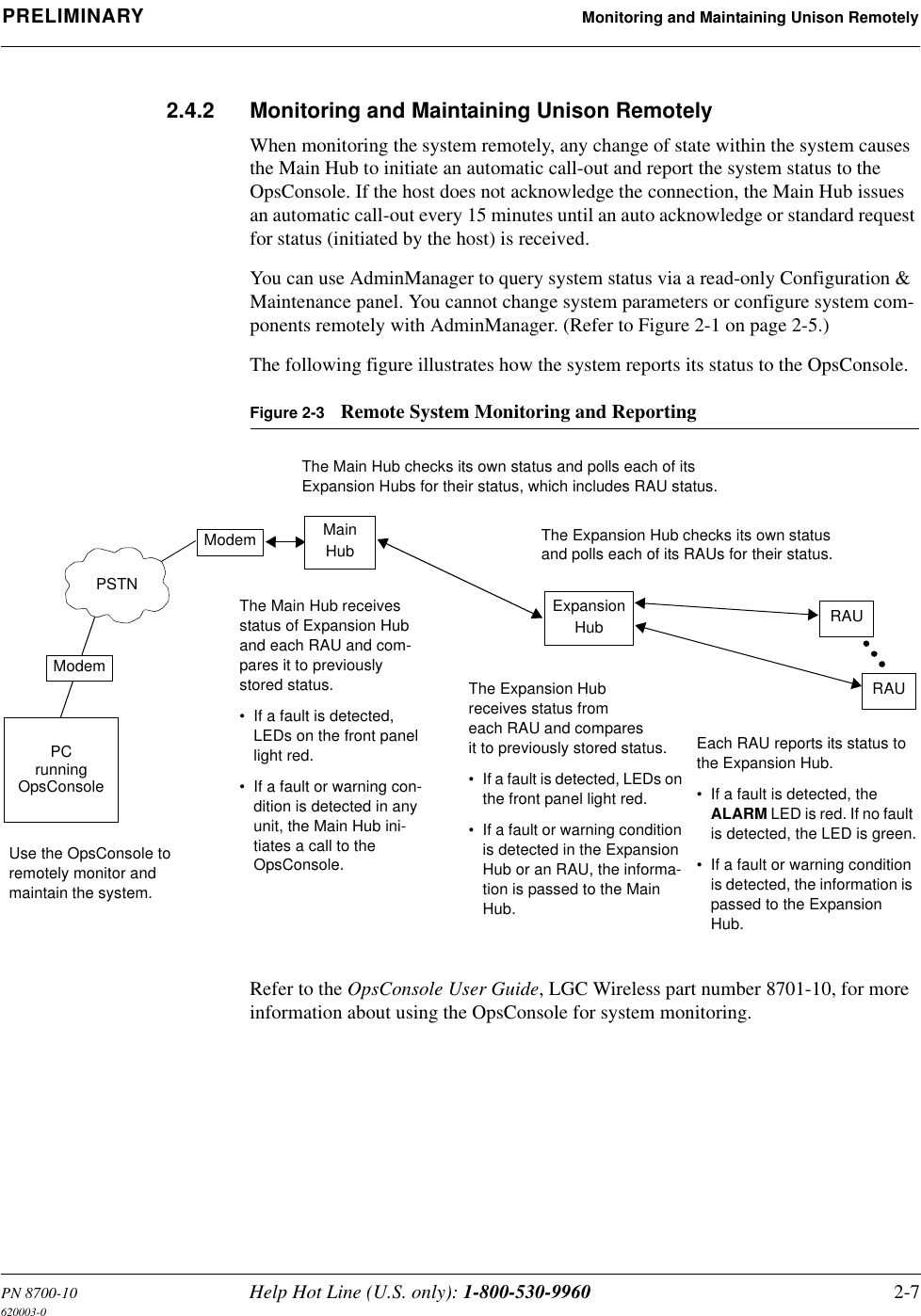
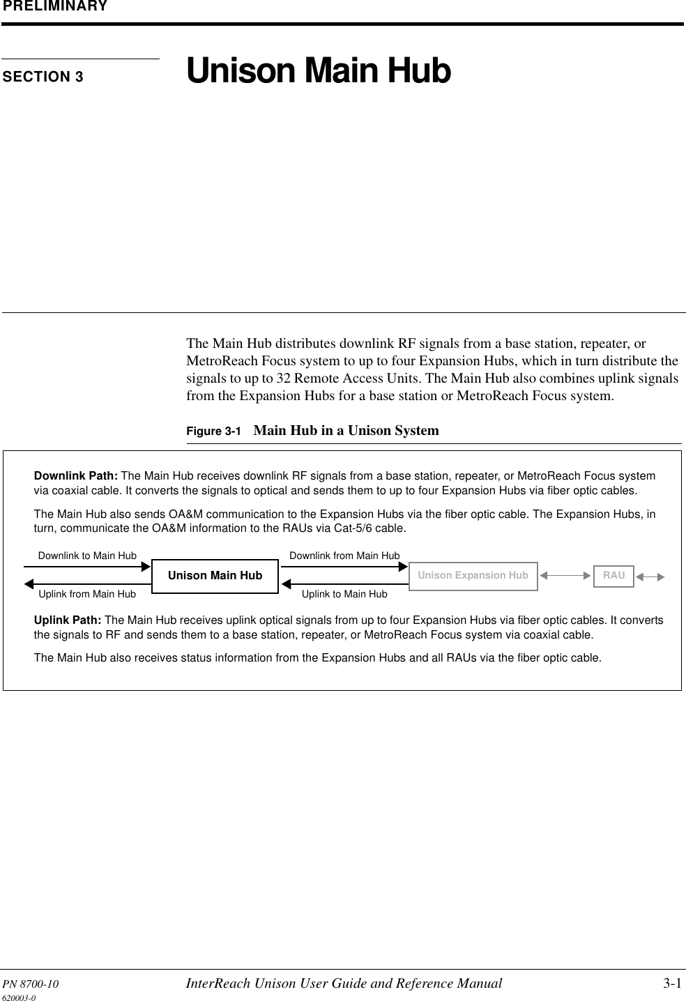
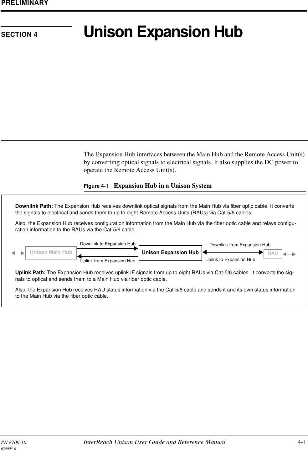
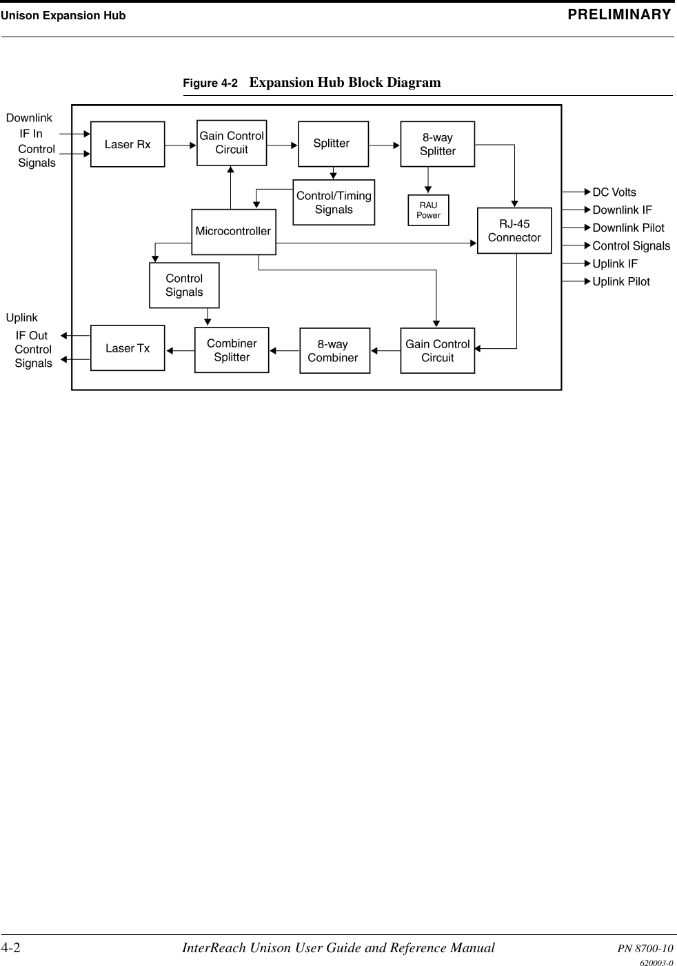
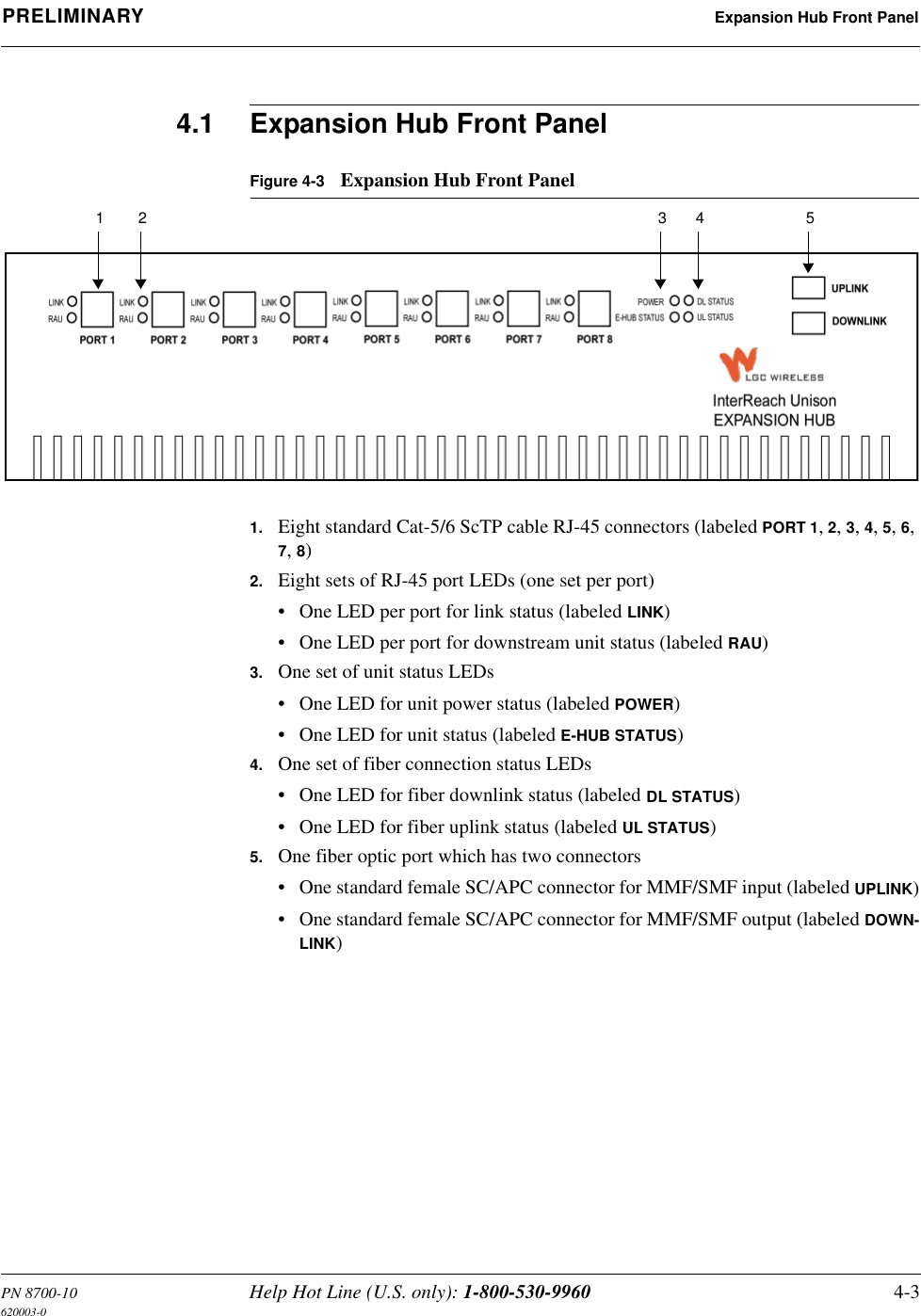
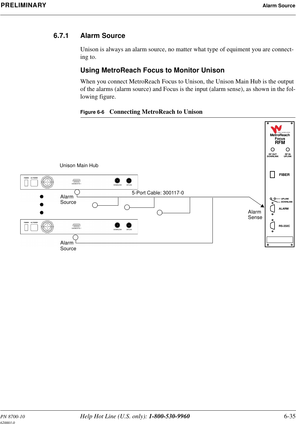
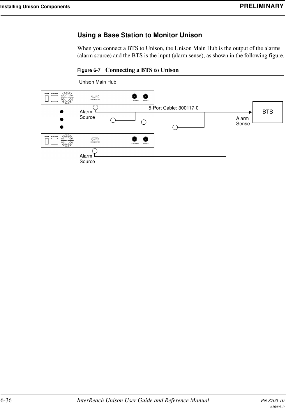
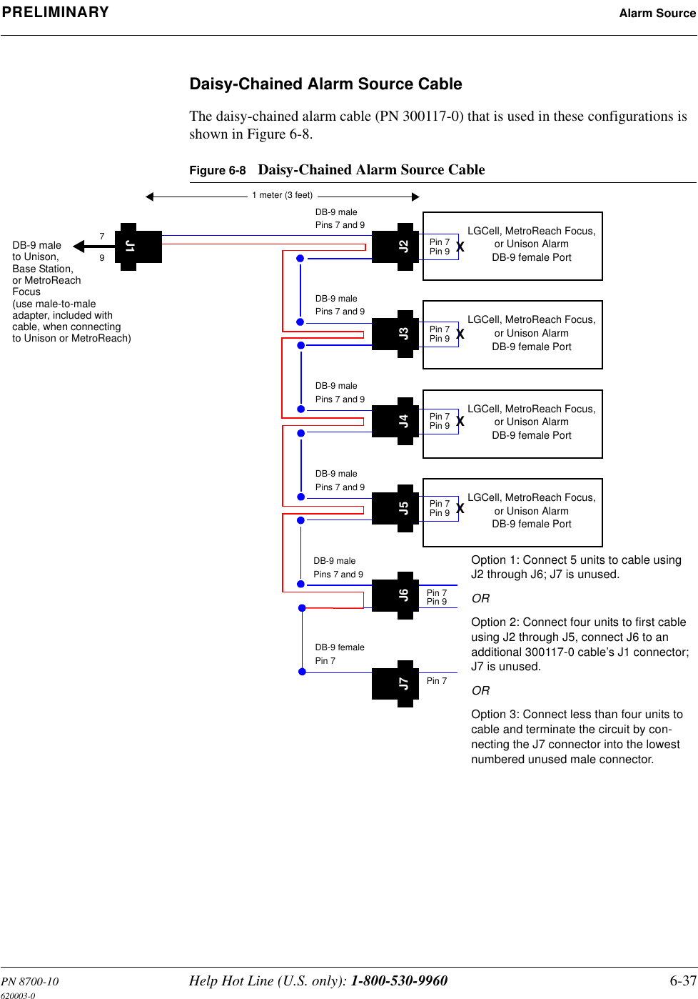
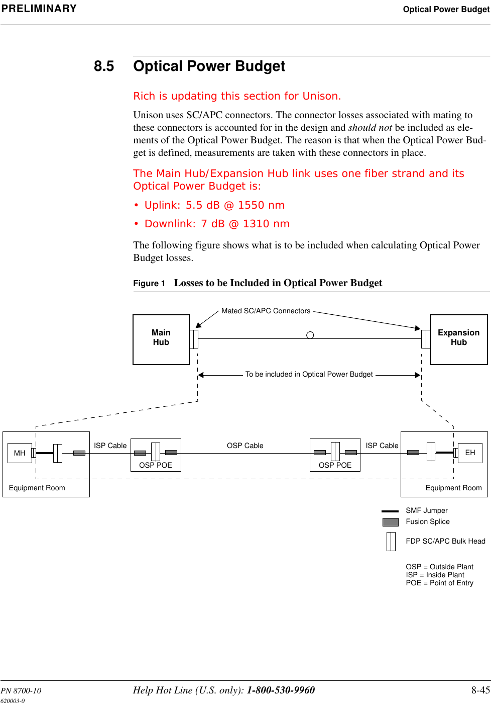
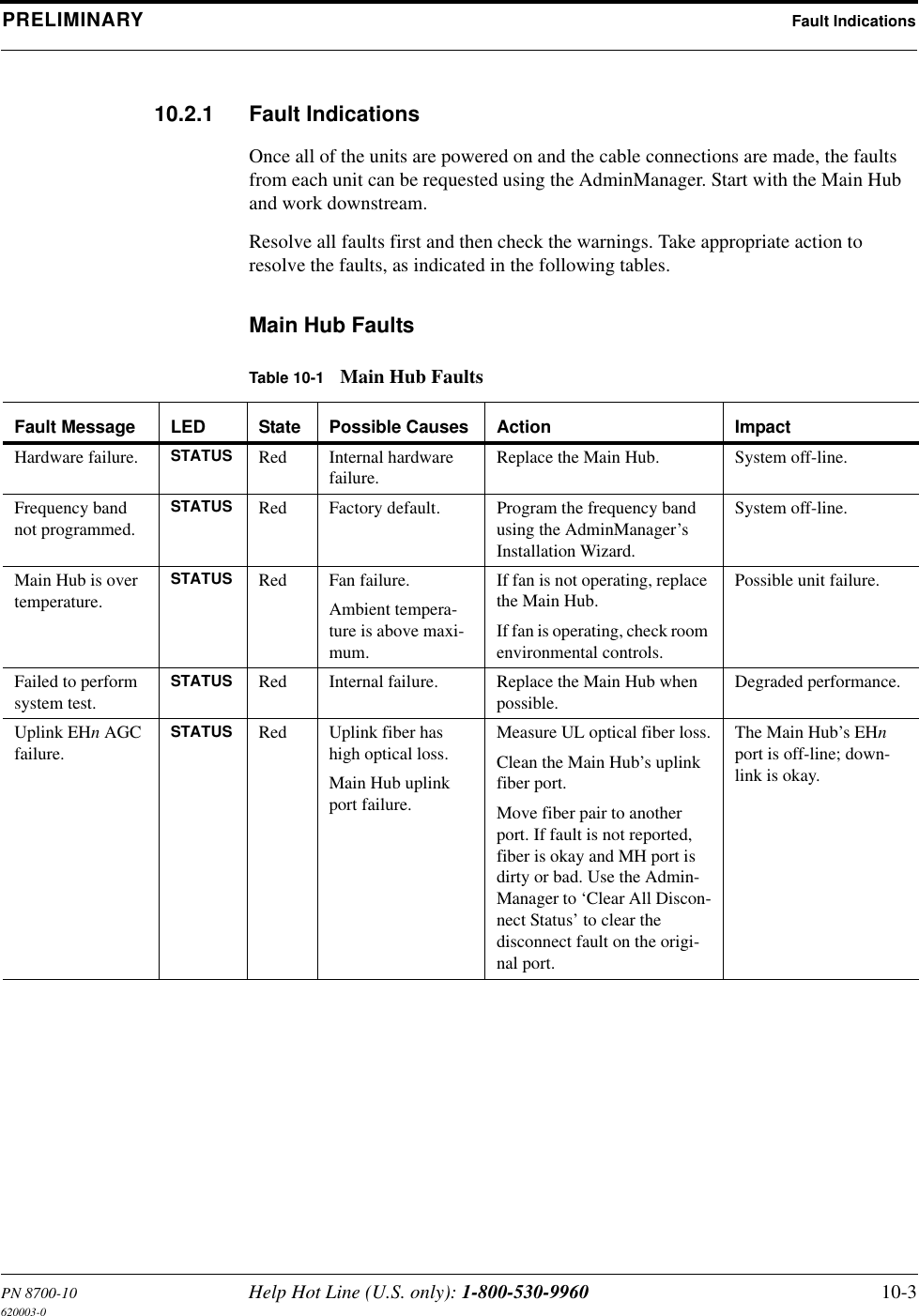
![InterReach™ Unison System Description PRELIMINARY2-2 InterReach Unison User Guide and Reference Manual PN 8700-10620003-0Key System Features•Superior RF performance, particularly in the areas of IP3 and noise figure.•High downlink composite power (+26 dBm), IP3 (+38 dBm) and low uplink noise figure (22 dB for a system with 8 RAUs), enables support of a large number of channels and larger coverage footprint per antenna.• The Main Hub and the Expansion Hub are software configurable. Thus, the fre-quency band can be field configured.• The system supports flexible cabling alternatives, allowing the use of either mul-timode or single-mode fiber (in addition to standard Cat-5 or Cat-6 [Cat-5/6] twisted pair). Cabling type can be selected to meet the resident cabling infrastruc-ture of the facility and unique building topologies.•Extended system “reach”. Using multimode fiber, fiber runs can be as long as 1.5 kilometers. Alternately, with single mode fiber the fiber run can be as long as 6 kilometers (creating a total system “wingspan” of 12 kilometers). And the Cat-5/6 twisted pair cable run can be up to 100 meters recommended maximum (150 meters with RF performance degradation).•Flexible RF configuration capabilities, including:• System gain:– Ability to manually set gain in 1 dB steps on both downlink and uplink.• RAU:– RAU uplink and downlink gain can be attenuated 10 dB.– Uplink level control protects the system from input overload and can be optimized for either a single operator or multi-operators/protocols.– VSWR check on RAU reports if there is a problem with the antenna.• The system firmware effectively “future proofs” the product. When any modi-fications are made to the product, including the addition of new software capabili-ties/services, systems that have already been installed can be upgraded simply by downloading new firmware (either locally or remotely).•Extensive OA&M capabilities, including fault isolation to the field replaceable unit, automatic reporting of all warnings and alarms, and user-friendly graphi-cal-user interface OA&M software packages.](https://usermanual.wiki/ADC-Telecommunications/UNS-EGSM-1/User-Guide-166431-Page-24.png)
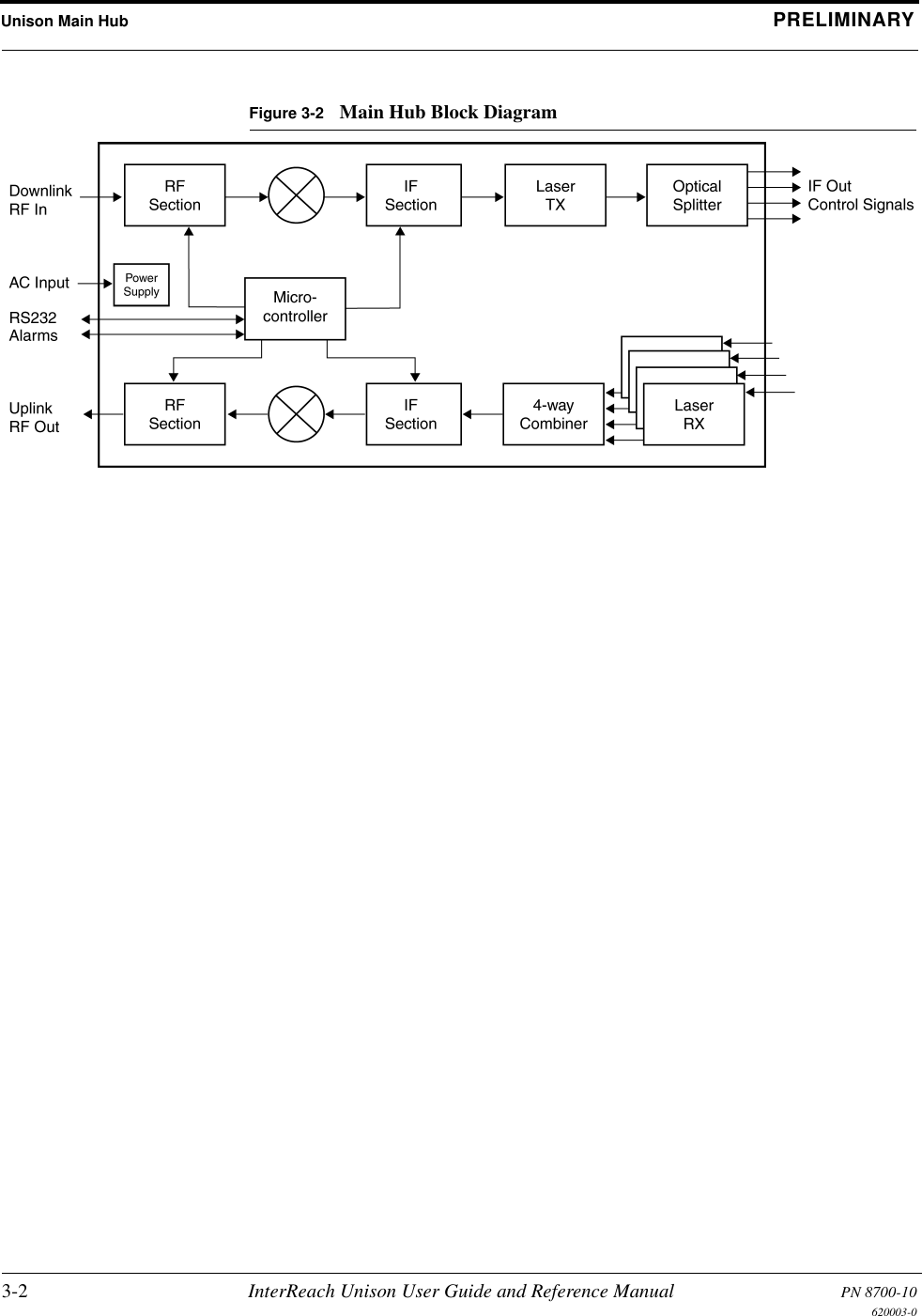

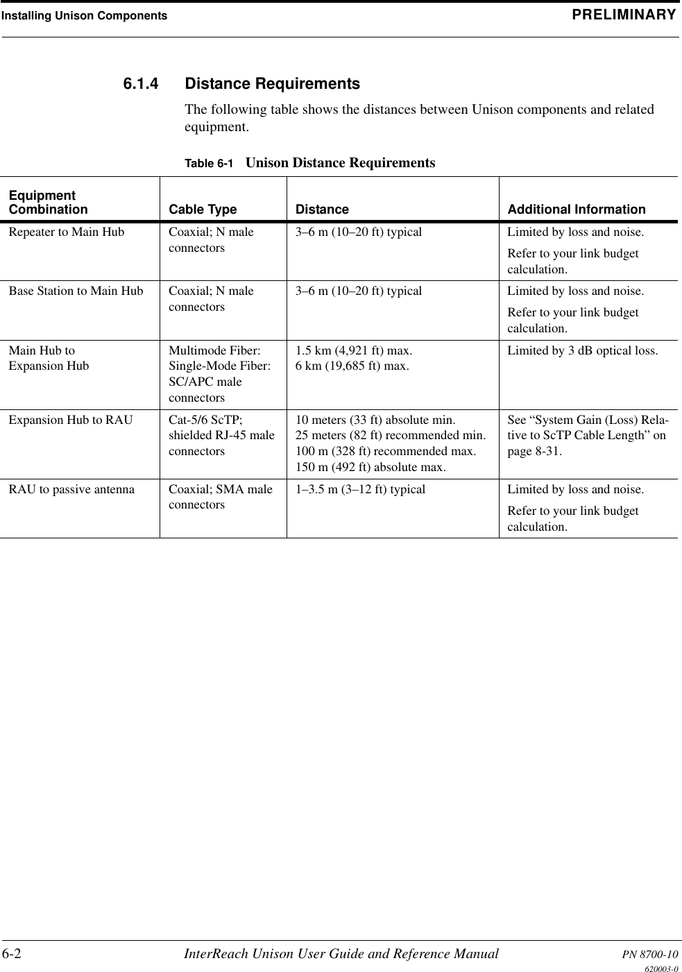
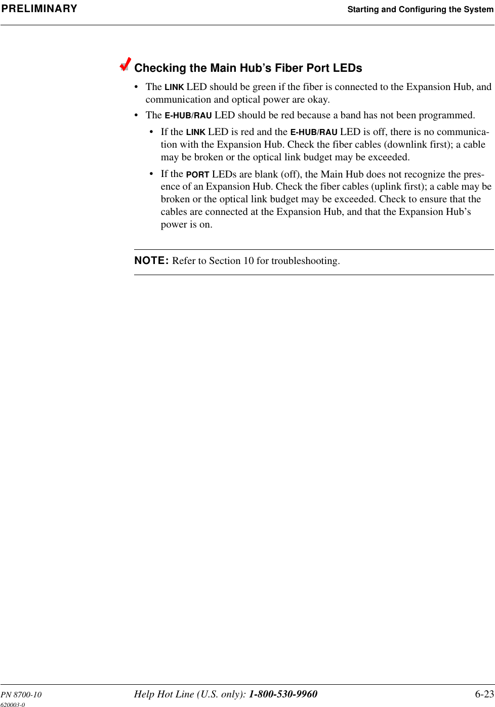
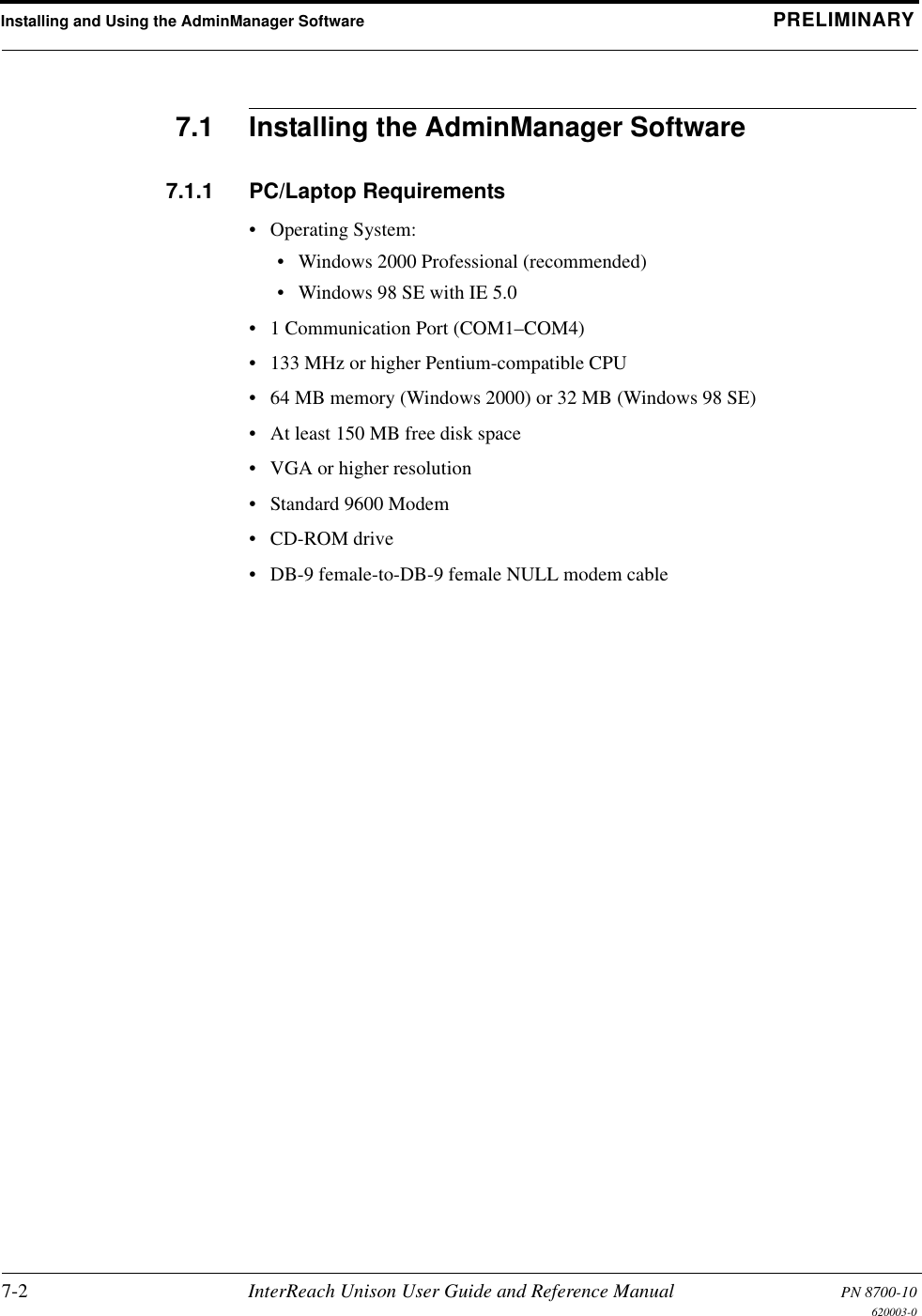
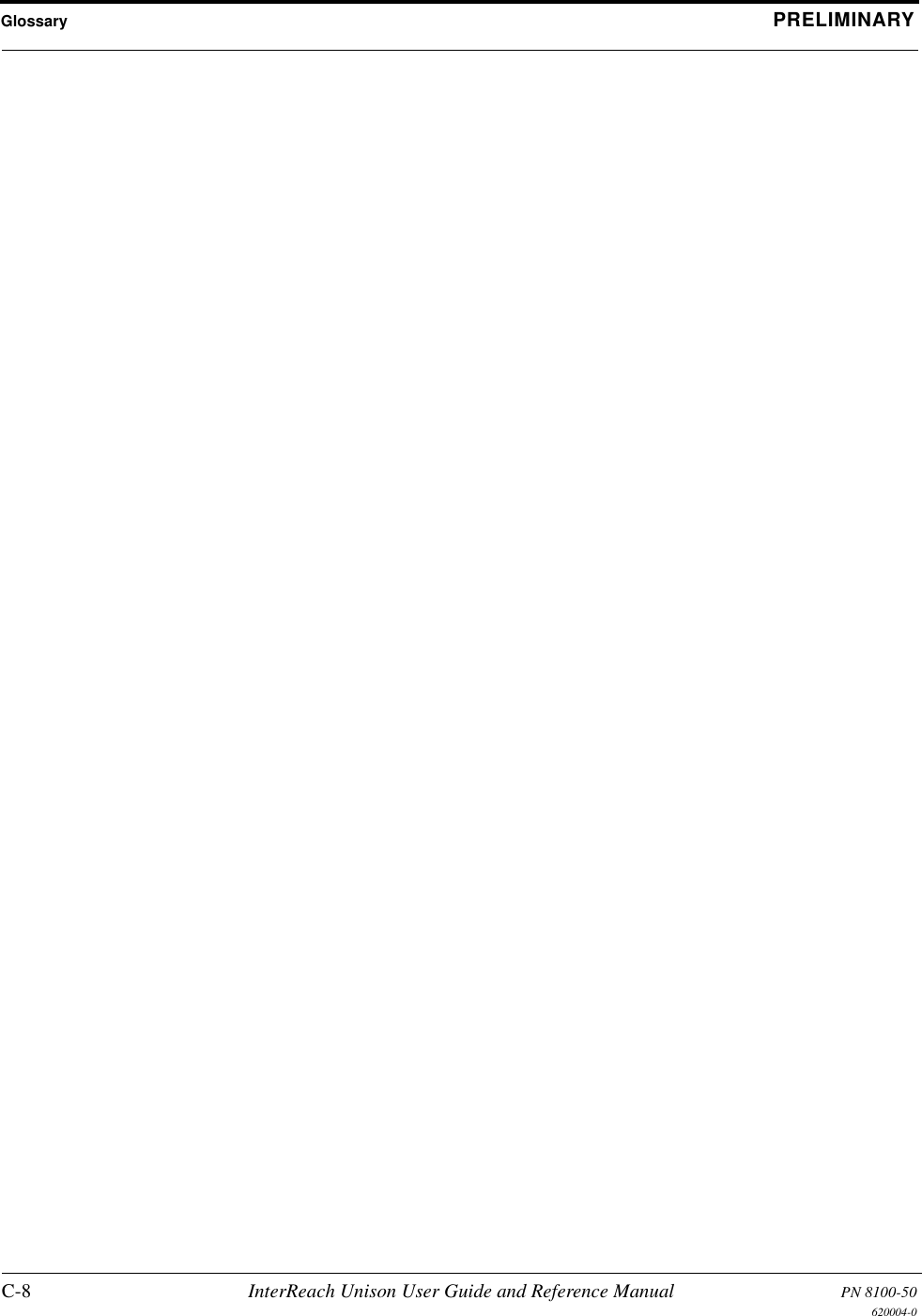
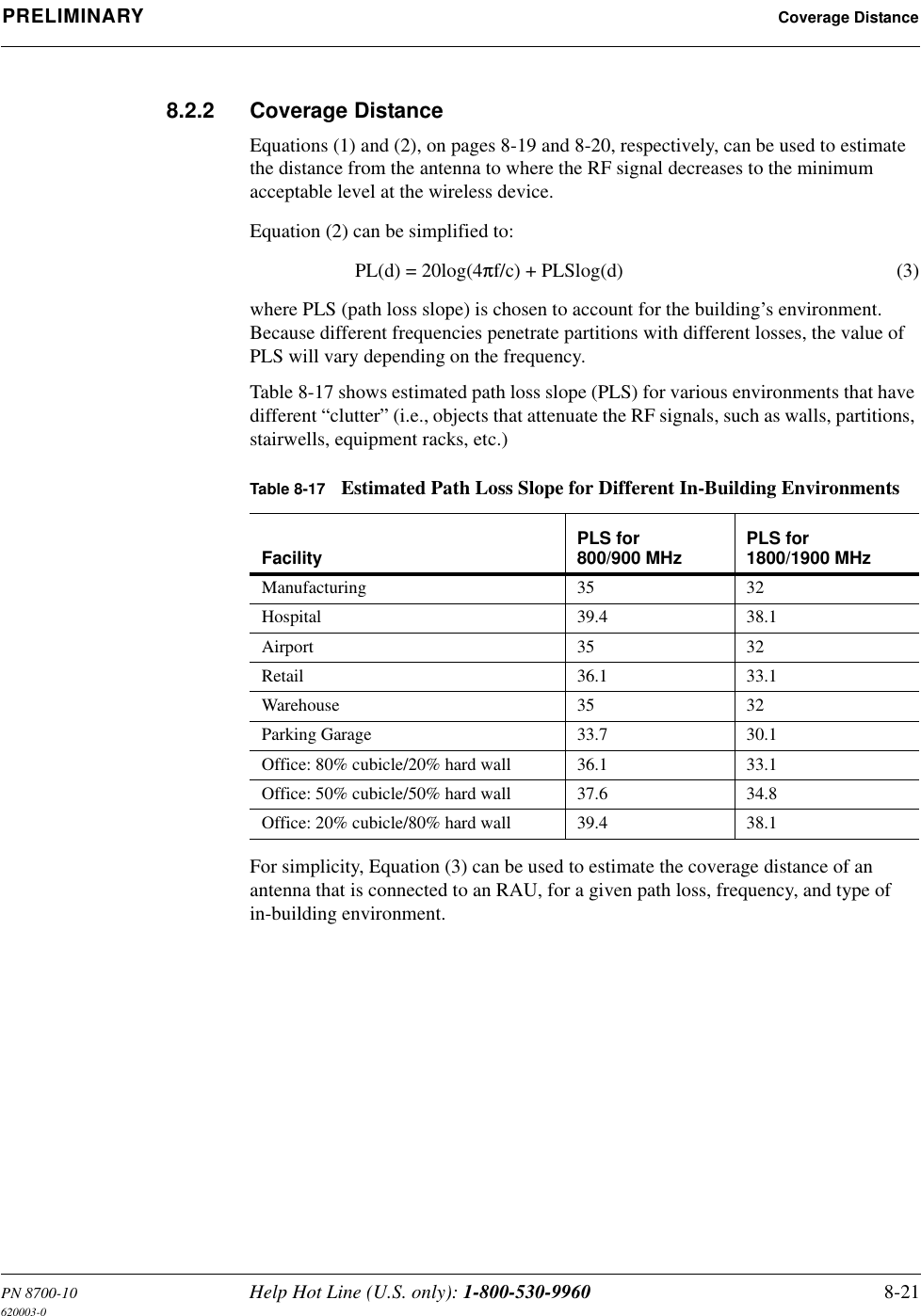
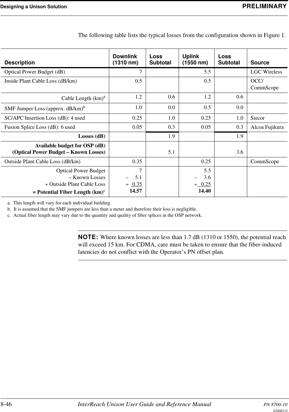
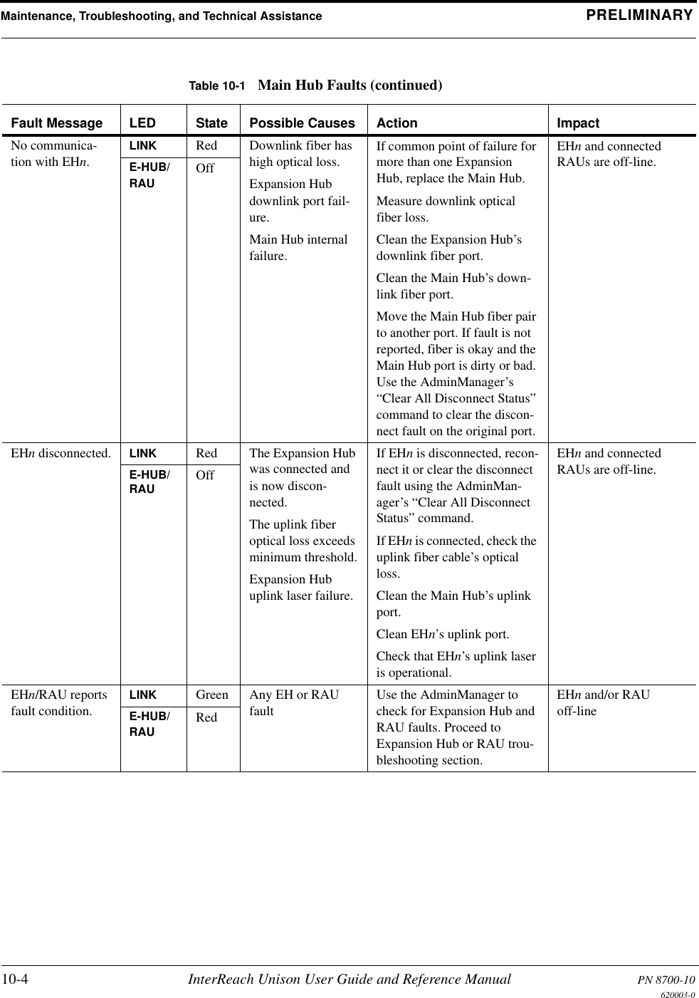
![PN 8700-10 Help Hot Line (U.S. only): 1-800-530-9960 7-29620003-0PRELIMINARY Options when Connected LocallyUsing the 10 dB Attenuation SettingBy selecting the Uplink and Downlink checkbox in the Advanced RAU Settings dia-log box, the uplink and downlink signals in the individual RAU, which you specified in the RAU Selection dialog box, are both reduced by 10 dB. One reason you may want to use this setting is to reduce the RAU’s output power when an RAU is located near an exterior wall of a building and its RF signal is going beyond the wall to the outside of the building, where it can negatively affect the outdoor macro system.The following table shows some examples of how the 10 dB attenuation setting affects coverage distance. These examples assume a 0 dB gain system, a 3 dBi gain antenna, and the difference between a –85 dB and a –75 dB design.You can use the following formula to calculate the reduction in distance covered.•dorig = original distance•dnew = new distance with 10 dB attenuation enabled• PLS = path loss slope [dB]dnew = (10–10/PLS)dorigExamples:dnew = 0.31 dorig for PLS = 20 dB (free space)dnew = 0.46 dorig for PLS = 30 dBFrequency Environment Reduction in Coverage Distance800 MHz Open, like a parking garage 24 meters (80 feet)800 MHz Heavily walled, like a Hospital 12.5 meters (41 feet)1900 MHz Open, like a parking garage 24 meters (80 feet)1900 MHz Heavily walled, like a Hospital 9 meters (30 feet)](https://usermanual.wiki/ADC-Telecommunications/UNS-EGSM-1/User-Guide-166431-Page-135.png)


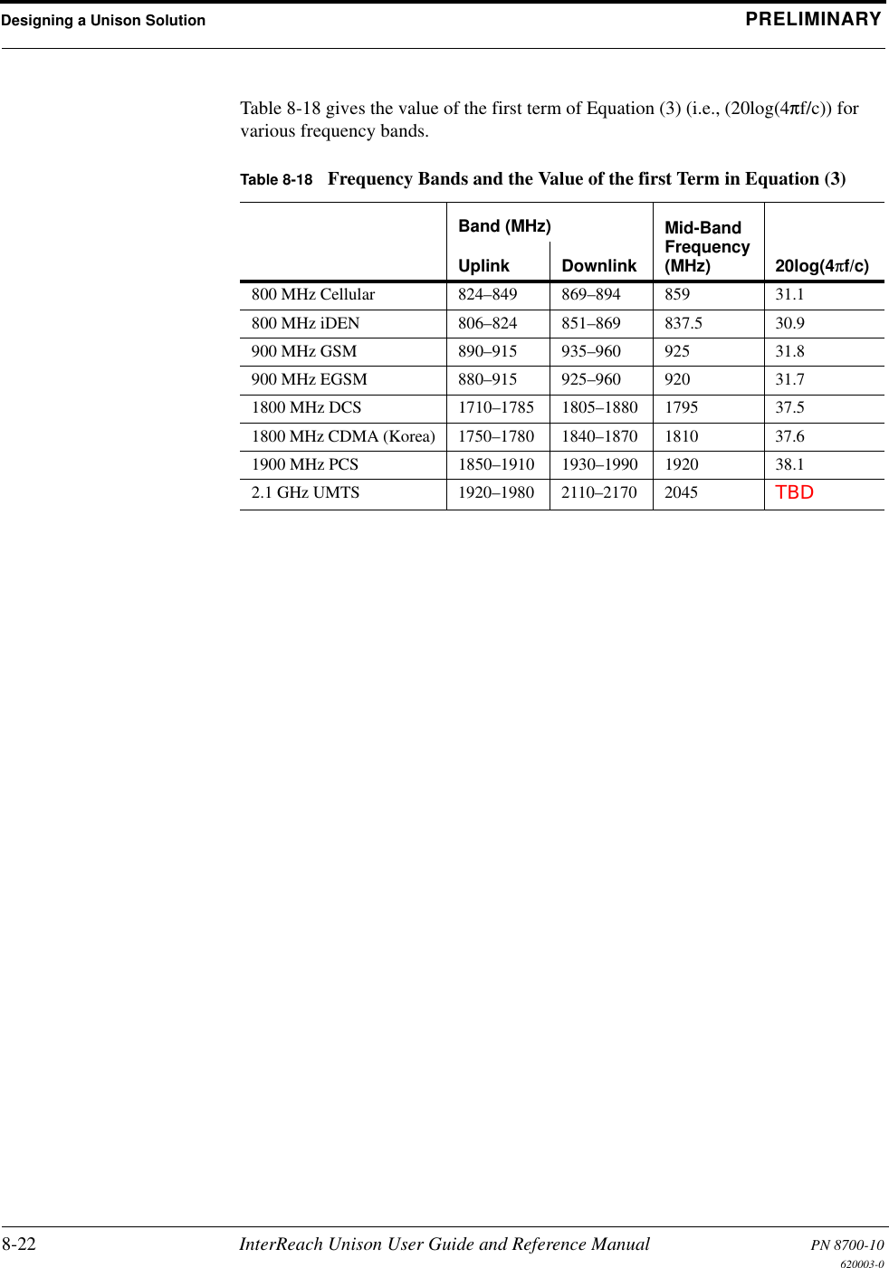

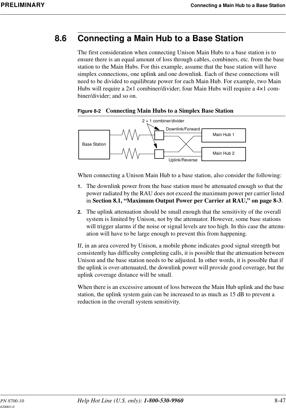
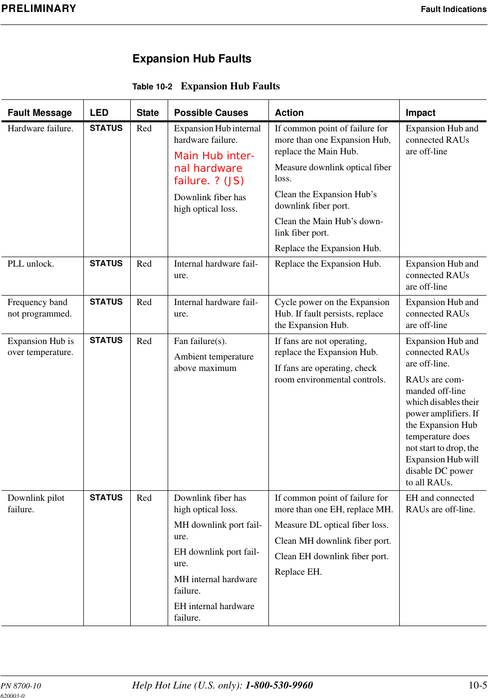
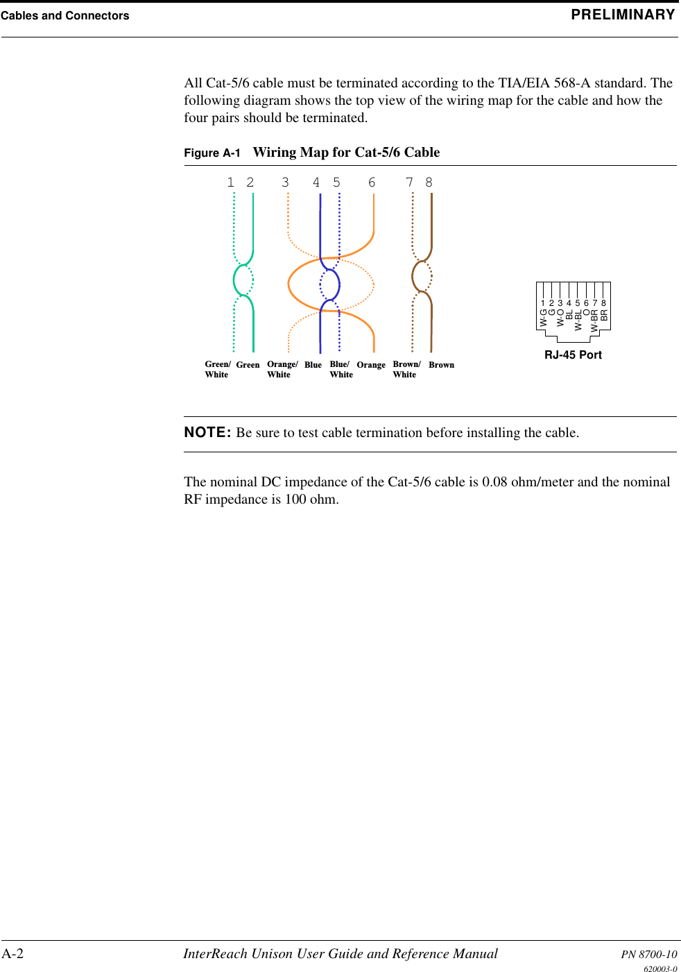
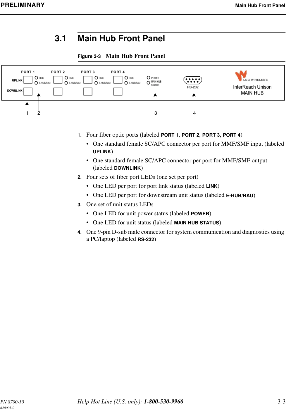
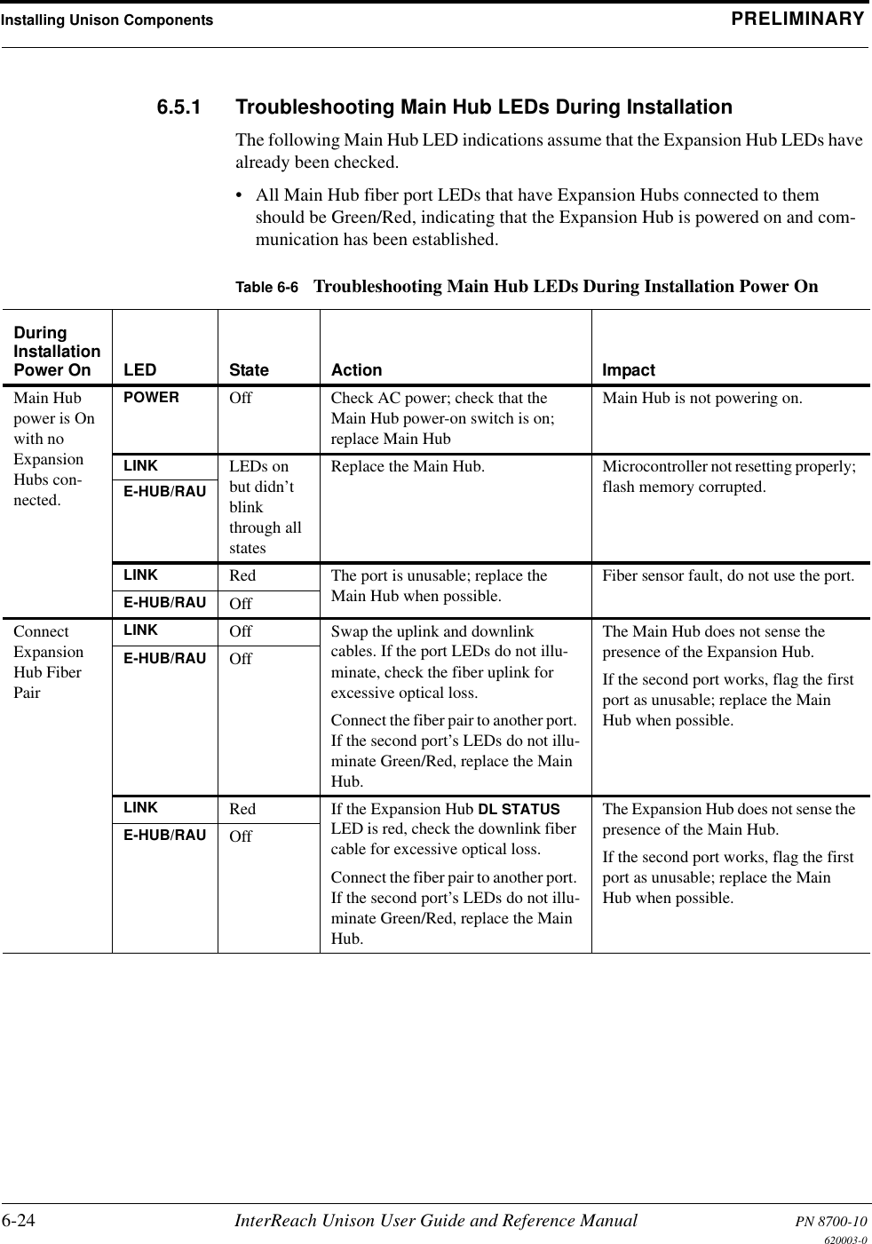
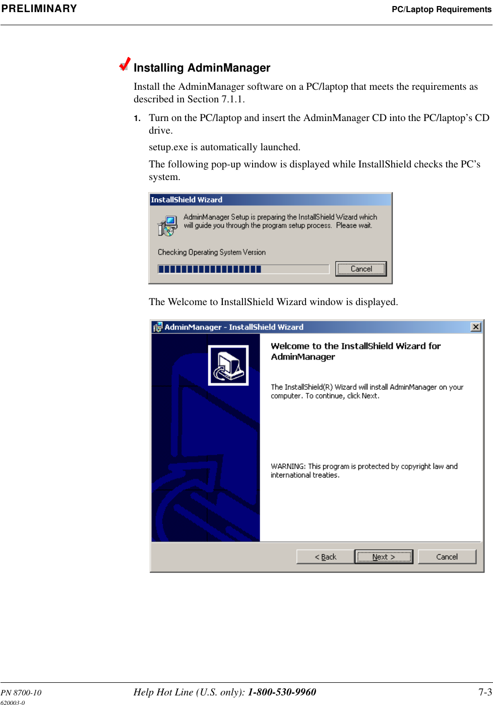
![PN 8700-10 Help Hot Line (U.S. only): 1-800-530-9960 A-3620003-0PRELIMINARY Fiber Optical CablesA.2 Fiber Optical Cables• Connects Main Hub to Expansion Hub(s)• Transmits (downlink) and receives (uplink) cellular and PCS signals• Use industry-standard 62.5µm/125µm MMF or Corning SMF-28 fiber, or equiva-lent (SC/APC [angle-polished] connectors only)• Distances:• Multimode Fiber: up to 1.5 km (4,921 ft) – 3 dB optical loss maximum• Single-Mode Fiber: up to 6 km (19,685 ft) – 3 dB optical loss maximumA.3 Coaxial Cable• Connects a Main Hub to a repeater or base station (N-type connectors)• Connects an RAU to a passive antenna (SMA connectors)](https://usermanual.wiki/ADC-Telecommunications/UNS-EGSM-1/User-Guide-166431-Page-219.png)