ADC Telecommunications UNS-EGSM-1 InterReach Unison EGSM User Manual unison
ADC Telecommunications Inc. InterReach Unison EGSM unison
User manual

PN 8700-10
620003-0
Installation, Operation,
and Reference Manual
InterReach Unison
TM

PN 8700-10
620003-0
Installation, Operation,
and Reference Manual
InterReach Unison
TM

InterReach Unison User Guide and Reference Manual PN 8700-10
620003-0
This manual is produced for use by LGC Wireless personnel, licensees, and customers. The
information contained herein is the property of LGC Wireless. No part of this document
may be reproduced or transmitted in any form or by any means, electronic or mechanical,
for any purpose, without the express written permission of LGC Wireless.
LGC Wireless reserves the right to make changes, without notice, to the specifications and
materials contained herein, and shall not be responsible for any damages caused by reliance
on the material as presented, including, but not limited to, typographical and listing errors.
Your comments are welcome – they help us improve our products and documentation.
Please address your comments to LGC Wireless, Inc. corporate headquarters in San Jose,
California:
Address 2540 Junction Avenue
San Jose, California
95134-1902 USA
Attn: Marketing Dept.
Phone 1-408-952-2400
Fax 1-408-952-2410
Help Hot Line 1-800-530-9960 (U.S. only)
+1-408-952-2400 (International)
+44(0) 1223 597812 (Europe)
Web Address http://www.lgcwireless.com
e-mail info@lgcwireless.com
service@lgcwireless.com
Copyright © 2001 by LGC Wireless, Inc. Printed in USA. All rights reserved.
Trademarks
All trademarks identified by ™ or ® are trademarks or registered trademark of LGC
Wireless, Inc. All other trademarks belong to their respective owners.

PN 8700-10 InterReach Unison User Guide and Reference Manual
620003-0
Limited Warranty
Seller warrants articles of its manufacture against defective materials or workmanship for a
period of one year from the date of shipment to Purchaser, except as provided in any warranty
applicable to Purchaser on or in the package containing the Goods (which warranty takes
precedence over the following warranty). The liability of Seller under the foregoing warranty
is limited, at Seller’s option, solely to repair or replacement with equivalent Goods, or an
appropriate adjustment not to exceed the sales price to Purchaser, provided that (a) Seller is
notified in writing by Purchaser, within the one year warranty period, promptly upon
discovery of defects, with a detailed description of such defects, (b) Purchaser has obtained a
Return Materials Authorization (RMA) from Seller, which RMA Seller agrees to provide
Purchaser promptly upon request, (c) the defective Goods are returned to Seller,
transportation and other applicable charges prepaid by the Purchaser, and (d) Seller’s
examination of such Goods discloses to its reasonable satisfaction that defects were not
caused by negligence, misuse, improper installation, improper maintenance, accident or
unauthorized repair or alteration or any other cause outside the scope of Purchaser’s warranty
made hereunder. Notwithstanding the foregoing, Seller shall have the option to repair any
defective Goods at Purchaser’s facility. The original warranty period for any Goods that have
been repaired or replaced by seller will not thereby be extended. In addition, all sales will be
subject to standard terms and conditions on the sales contract.

InterReach Unison User Guide and Reference Manual PN 8700-10
620003-0

PN8700-10 InterReach Unison User Guide and Reference Manual i
620003-0
PRELIMINARY
Table of Contents
SECTION 1 General Information . . . . . . . . . . . . . . . . . . . . . . 1-1
1.1 Purpose and Scope . . . . . . . . . . . . . . . . . . . . . . . . . . . . . . . . . 1-2
1.2 Conventions in this Manual . . . . . . . . . . . . . . . . . . . . . . . . . . 1-3
1.3 Acronyms in this Manual . . . . . . . . . . . . . . . . . . . . . . . . . . . . 1-4
1.4 Standards Conformance . . . . . . . . . . . . . . . . . . . . . . . . . . . . . 1-6
1.5 Related Publications . . . . . . . . . . . . . . . . . . . . . . . . . . . . . . . . 1-6
SECTION 2 InterReach™ Unison System Description . . . . 2-1
2.1 System Overview . . . . . . . . . . . . . . . . . . . . . . . . . . . . . . . . . . 2-1
2.2 System Hardware . . . . . . . . . . . . . . . . . . . . . . . . . . . . . . . . . . 2-3
2.3 System Software . . . . . . . . . . . . . . . . . . . . . . . . . . . . . . . . . . . 2-4
2.4 System OA&M Capabilities . . . . . . . . . . . . . . . . . . . . . . . . . . 2-5
2.4.1 Configuring, Maintaining, and Monitoring Unison Locally . . 2-6
2.4.2 Monitoring and Maintaining Unison Remotely . . . . . . . . . . . 2-7
2.4.3 Using Alarm Contact Closures . . . . . . . . . . . . . . . . . . . . . . . . 2-8
2.5 System Connectivity . . . . . . . . . . . . . . . . . . . . . . . . . . . . . . . . 2-9
2.6 System Operation . . . . . . . . . . . . . . . . . . . . . . . . . . . . . . . . . 2-10
2.7 System Specifications . . . . . . . . . . . . . . . . . . . . . . . . . . . . . . 2-11
2.7.1 Physical Specifications . . . . . . . . . . . . . . . . . . . . . . . . . . . . . 2-11
2.7.2 Environmental Specifications . . . . . . . . . . . . . . . . . . . . . . . . 2-12
2.7.3 Operating Frequencies . . . . . . . . . . . . . . . . . . . . . . . . . . . . . . 2-12
2.7.4 RF End-to-End Performance . . . . . . . . . . . . . . . . . . . . . . . . . 2-13
SECTION 3 Unison Main Hub . . . . . . . . . . . . . . . . . . . . . . . . 3-1
3.1 Main Hub Front Panel . . . . . . . . . . . . . . . . . . . . . . . . . . . . . . 3-3
3.1.1 Optical Fiber Uplink/Downlink Ports . . . . . . . . . . . . . . . . . . . 3-4
3.1.2 Communications RS-232 Serial Connector . . . . . . . . . . . . . . 3-4
3.1.3 LED Indicators . . . . . . . . . . . . . . . . . . . . . . . . . . . . . . . . . . . . 3-6
3.2 Main Hub Rear Panel . . . . . . . . . . . . . . . . . . . . . . . . . . . . . . . 3-8
3.2.1 Main Hub Rear Panel Connectors . . . . . . . . . . . . . . . . . . . . . . 3-9
3.2.1.1 N-type Female Connectors . . . . . . . . . . . . . . . . . . . . . . 3-9

PRELIMINARY
ii InterReach Unison User Guide and Reference Manual PN8700-10
620003-0
3.2.1.2 9-pin D-sub Connector . . . . . . . . . . . . . . . . . . . . . . . . . . 3-9
3.3 Faults and Warnings . . . . . . . . . . . . . . . . . . . . . . . . . . . . . . . 3-10
3.4 Main Hub Specifications . . . . . . . . . . . . . . . . . . . . . . . . . . . . 3-11
SECTION 4 Unison Expansion Hub . . . . . . . . . . . . . . . . . . . . 4-1
4.1 Expansion Hub Front Panel . . . . . . . . . . . . . . . . . . . . . . . . . . 4-3
4.1.1 RJ-45 Connectors . . . . . . . . . . . . . . . . . . . . . . . . . . . . . . . . . . . 4-4
4.1.2 Optical Fiber Uplink/Downlink Connectors . . . . . . . . . . . . . . 4-4
4.1.3 LED Indicators . . . . . . . . . . . . . . . . . . . . . . . . . . . . . . . . . . . . . 4-5
4.2 Expansion Hub Rear Panel . . . . . . . . . . . . . . . . . . . . . . . . . . . 4-7
4.3 Faults and Warnings . . . . . . . . . . . . . . . . . . . . . . . . . . . . . . . . 4-8
4.4 Expansion Hub Specifications . . . . . . . . . . . . . . . . . . . . . . . . 4-9
SECTION 5 Unison Remote Access Unit . . . . . . . . . . . . . . . 5-1
5.1 Remote Access Unit Connectors . . . . . . . . . . . . . . . . . . . . . . . 5-3
5.1.1 SMA Connector . . . . . . . . . . . . . . . . . . . . . . . . . . . . . . . . . . . . 5-3
5.1.2 RJ-45 Port . . . . . . . . . . . . . . . . . . . . . . . . . . . . . . . . . . . . . . . . 5-3
5.2 LED Indicators . . . . . . . . . . . . . . . . . . . . . . . . . . . . . . . . . . . . 5-3
5.3 Faults and Warnings . . . . . . . . . . . . . . . . . . . . . . . . . . . . . . . . 5-4
5.4 Remote Access Unit Specifications . . . . . . . . . . . . . . . . . . . . 5-5
SECTION 6 Installing Unison Components . . . . . . . . . . . . . 6-1
6.1 Installation Requirements . . . . . . . . . . . . . . . . . . . . . . . . . . . . 6-1
6.1.1 Component Location Requirements . . . . . . . . . . . . . . . . . . . . 6-1
6.1.2 Cable and Connector Requirements . . . . . . . . . . . . . . . . . . . . 6-1
6.1.3 Neutral Host System Requirements . . . . . . . . . . . . . . . . . . . . . 6-1
6.1.4 Distance Requirements . . . . . . . . . . . . . . . . . . . . . . . . . . . . . . 6-2
6.2 Safety Precautions . . . . . . . . . . . . . . . . . . . . . . . . . . . . . . . . . . 6-3
6.2.1 Installation Guidelines . . . . . . . . . . . . . . . . . . . . . . . . . . . . . . . 6-3
6.2.2 General Safety Precautions . . . . . . . . . . . . . . . . . . . . . . . . . . . 6-3
6.2.3 Fiber Port Safety Precautions . . . . . . . . . . . . . . . . . . . . . . . . . 6-4
6.3 Preparing for System Installation . . . . . . . . . . . . . . . . . . . . . . 6-5
6.3.1 Pre-Installation Inspection . . . . . . . . . . . . . . . . . . . . . . . . . . . . 6-5
6.3.2 Installation Checklist . . . . . . . . . . . . . . . . . . . . . . . . . . . . . . . . 6-6
6.3.3 Tools and Materials Required . . . . . . . . . . . . . . . . . . . . . . . . . 6-8
6.3.4 Optional Accessories . . . . . . . . . . . . . . . . . . . . . . . . . . . . . . . . 6-8
6.4 Unison Component Installation Procedures . . . . . . . . . . . . . . 6-9
6.4.1 Installing RAUs and Passive Antennas . . . . . . . . . . . . . . . . . 6-11
6.4.1.1 Installing RAUs in a Neutral Host System . . . . . . . . . 6-12
6.4.2 Installing Expansion Hubs . . . . . . . . . . . . . . . . . . . . . . . . . . . 6-13
6.4.2.1 Troubleshooting Expansion Hub LEDs During
Installation . . . . . . . . . . . . . . . . . . . . . . . . . . . . . . . . . . 6-18
6.4.2.2 Installing Expansion Hubs in a Neutral Host System . 6-18
6.4.3 Installing a Main Hub . . . . . . . . . . . . . . . . . . . . . . . . . . . . . . 6-19

PRELIMINARY
PN8700-10 InterReach Unison User Guide and Reference Manual iii
620003-0
6.4.4 Installing Main Hubs in a Neutral Host System . . . . . . . . . . 6-20
6.5 Starting and Configuring the System . . . . . . . . . . . . . . . . . . 6-21
6.5.1 Troubleshooting Main Hub LEDs During Installation . . . . . 6-24
6.6 Interfacing a Main Hub to a Base Station or Roof-top
Antenna . . . . . . . . . . . . . . . . . . . . . . . . . . . . . . . . . . . . . . . . . 6-26
6.6.1 Connecting Multiple Main Hubs . . . . . . . . . . . . . . . . . . . . . . 6-30
6.7 Connecting Contact Alarms to a Unison System . . . . . . . . . 6-34
6.7.1 Alarm Source . . . . . . . . . . . . . . . . . . . . . . . . . . . . . . . . . . . . . 6-35
6.7.2 Alarm Sense . . . . . . . . . . . . . . . . . . . . . . . . . . . . . . . . . . . . . 6-38
SECTION 7 Installing and Using the AdminManager
Software . . . . . . . . . . . . . . . . . . . . . . . . . . . . . . . . 7-1
7.1 Installing the AdminManager Software . . . . . . . . . . . . . . . . . 7-2
7.1.1 PC/Laptop Requirements . . . . . . . . . . . . . . . . . . . . . . . . . . . . 7-2
7.2 Installation Wizard . . . . . . . . . . . . . . . . . . . . . . . . . . . . . . . . 7-12
7.2.1 Step 1: Verify Hardware . . . . . . . . . . . . . . . . . . . . . . . . . . . . 7-13
7.2.1.1 Description of Step 1 Panel . . . . . . . . . . . . . . . . . . . . . 7-14
7.2.2 Step 2: Set Operation Band . . . . . . . . . . . . . . . . . . . . . . . . . . 7-15
7.2.2.1 Description of Step 2 Panel . . . . . . . . . . . . . . . . . . . . . 7-17
7.2.3 Step 3: Configure System Parameters . . . . . . . . . . . . . . . . . . 7-19
7.2.3.1 Description of Step 3 Panel . . . . . . . . . . . . . . . . . . . . . 7-20
7.2.4 Step 4: Final System Test . . . . . . . . . . . . . . . . . . . . . . . . . . . 7-21
7.2.4.1 Description of Step 4 Panel . . . . . . . . . . . . . . . . . . . . . 7-22
7.2.5 Finish Panel . . . . . . . . . . . . . . . . . . . . . . . . . . . . . . . . . . . . . . 7-23
7.2.5.1 Description of Finish Panel . . . . . . . . . . . . . . . . . . . . . 7-23
7.3 Configuration & Maintenance Panel . . . . . . . . . . . . . . . . . . 7-24
7.3.1 Window Description . . . . . . . . . . . . . . . . . . . . . . . . . . . . . . . 7-25
7.3.2 Options when Connected Locally . . . . . . . . . . . . . . . . . . . . . 7-28
7.3.3 Read-Only Options when Connected Remotely . . . . . . . . . . 7-33
7.4 Upgrading Firmware . . . . . . . . . . . . . . . . . . . . . . . . . . . . . . . 7-37
7.5 System Status Tree . . . . . . . . . . . . . . . . . . . . . . . . . . . . . . . . 7-38
7.5.1 System Status Tree Icons . . . . . . . . . . . . . . . . . . . . . . . . . . . . 7-38
SECTION 8 Designing a Unison Solution . . . . . . . . . . . . . . . 8-1
8.1 Maximum Output Power per Carrier at RAU . . . . . . . . . . . . . 8-3
8.2 Estimating RF Coverage . . . . . . . . . . . . . . . . . . . . . . . . . . . . 8-19
8.2.1 Path Loss Equation . . . . . . . . . . . . . . . . . . . . . . . . . . . . . . . . 8-20
8.2.2 Coverage Distance . . . . . . . . . . . . . . . . . . . . . . . . . . . . . . . . . 8-21
8.2.3 Examples of Design Estimates . . . . . . . . . . . . . . . . . . . . . . . 8-27
8.3 System Gain . . . . . . . . . . . . . . . . . . . . . . . . . . . . . . . . . . . . . 8-31
8.3.1 System Gain (Loss) Relative to ScTP Cable Length . . . . . . 8-31
8.4 Link Budget Analysis . . . . . . . . . . . . . . . . . . . . . . . . . . . . . . 8-32
8.4.1 Elements of a Link Budget for Narrowband Standards . . . . 8-33
8.4.2 Narrowband Link Budget Analysis for a Microcell
Application . . . . . . . . . . . . . . . . . . . . . . . . . . . . . . . . . . . . . . 8-35

PRELIMINARY
iv InterReach Unison User Guide and Reference Manual PN8700-10
620003-0
8.4.3 Elements of a Link Budget for CDMA Standards . . . . . . . . . 8-37
8.4.4 Spread Spectrum Link Budget Analysis for a Microcell
Application . . . . . . . . . . . . . . . . . . . . . . . . . . . . . . . . . . . . . . 8-40
8.4.5 Considerations for Re-Radiation (over-the-air) Systems . . . . 8-44
8.5 Optical Power Budget . . . . . . . . . . . . . . . . . . . . . . . . . . . . . . 8-45
8.6 Connecting a Main Hub to a Base Station . . . . . . . . . . . . . . 8-47
8.6.1 Attenuation . . . . . . . . . . . . . . . . . . . . . . . . . . . . . . . . . . . . . . 8-48
8.6.2 Uplink Attenuation . . . . . . . . . . . . . . . . . . . . . . . . . . . . . . . . 8-49
8.6.2.1 Uplink Attenuation Exception: CDMA . . . . . . . . . . . . 8-50
8.7 Designing for a Neutral Host System . . . . . . . . . . . . . . . . . . 8-51
8.7.1 Capacity of the Unison Neutral Host System . . . . . . . . . . . . 8-51
8.7.2 Example Unison Neutral Host System . . . . . . . . . . . . . . . . . 8-52
SECTION 9 Replacing Unison Components in an
Operating System . . . . . . . . . . . . . . . . . . . . . . . . 9-1
9.1 Replacing an RAU . . . . . . . . . . . . . . . . . . . . . . . . . . . . . . . . . 9-1
9.2 Replacing an Expansion Hub . . . . . . . . . . . . . . . . . . . . . . . . . 9-3
9.3 Replacing a Main Hub . . . . . . . . . . . . . . . . . . . . . . . . . . . . . . 9-4
SECTION 10 Maintenance, Troubleshooting, and
Technical Assistance . . . . . . . . . . . . . . . . . . . . 10-1
10.1 Maintenance . . . . . . . . . . . . . . . . . . . . . . . . . . . . . . . . . . . . . 10-1
10.2 Troubleshooting . . . . . . . . . . . . . . . . . . . . . . . . . . . . . . . . . . 10-2
10.2.1 Fault Indications . . . . . . . . . . . . . . . . . . . . . . . . . . . . . . . . . . 10-3
10.2.2 Warning Indications . . . . . . . . . . . . . . . . . . . . . . . . . . . . . . . . 10-8
10.3 LED Troubleshooting Guide . . . . . . . . . . . . . . . . . . . . . . . 10-10
10.3.1 Troubleshooting Main Hub LEDs During Normal Operation . 10-
11
10.3.2 Troubleshooting Expansion Hub LEDs During Normal
Operation . . . . . . . . . . . . . . . . . . . . . . . . . . . . . . . . . . . . . . 10-12
10.4 Technical Assistance . . . . . . . . . . . . . . . . . . . . . . . . . . . . . 10-14
APPENDIX A Cables and Connectors . . . . . . . . . . . . . . . . . . . A-1
A.1 Cat-5/6 Cable (ScTP) . . . . . . . . . . . . . . . . . . . . . . . . . . . . . . .A-1
A.2 Fiber Optical Cables . . . . . . . . . . . . . . . . . . . . . . . . . . . . . . . .A-3
A.3 Coaxial Cable . . . . . . . . . . . . . . . . . . . . . . . . . . . . . . . . . . . . .A-3
APPENDIX B Compliance . . . . . . . . . . . . . . . . . . . . . . . . . . . . . B-1
B.1 Safety Requirements . . . . . . . . . . . . . . . . . . . . . . . . . . . . . . . . C-1
B.2 Radio/EMC Requirements . . . . . . . . . . . . . . . . . . . . . . . . . . .C-2
APPENDIX C Glossary . . . . . . . . . . . . . . . . . . . . . . . . . . . . . . . . C-1

PN8700-10 InterReach Unison User Guide and Reference Manual v
620003-0
PRELIMINARY
List of Figures
Figure 2-1 OA&M Communications . . . . . . . . . . . . . . . . . . . . . . . . . . . . . . . . . . . . 2-5
Figure 2-2 Local System Monitoring and Reporting . . . . . . . . . . . . . . . . . . . . . . . 2-6
Figure 2-3 Remote System Monitoring and Reporting . . . . . . . . . . . . . . . . . . . . . . 2-7
Figure 2-4 Unison’s Double Star Architecture . . . . . . . . . . . . . . . . . . . . . . . . . . . . 2-9
Figure 3-1 Main Hub in a Unison System . . . . . . . . . . . . . . . . . . . . . . . . . . . . . . . . 3-1
Figure 3-2 Main Hub Block Diagram . . . . . . . . . . . . . . . . . . . . . . . . . . . . . . . . . . . 3-2
Figure 3-3 Main Hub Front Panel . . . . . . . . . . . . . . . . . . . . . . . . . . . . . . . . . . . . . . 3-3
Figure 3-4 Standard Serial Cable Pinout . . . . . . . . . . . . . . . . . . . . . . . . . . . . . . . . . 3-4
Figure 3-5 Null Modem Cable Pinout . . . . . . . . . . . . . . . . . . . . . . . . . . . . . . . . . . . 3-5
Figure 3-6 Main Hub Rear Panel . . . . . . . . . . . . . . . . . . . . . . . . . . . . . . . . . . . . . . . 3-8
Figure 4-1 Expansion Hub in a Unison System . . . . . . . . . . . . . . . . . . . . . . . . . . . . 4-1
Figure 4-2 Expansion Hub Block Diagram . . . . . . . . . . . . . . . . . . . . . . . . . . . . . . . 4-2
Figure 4-3 Expansion Hub Front Panel . . . . . . . . . . . . . . . . . . . . . . . . . . . . . . . . . . 4-3
Figure 4-4 Expansion Hub Rear Panel . . . . . . . . . . . . . . . . . . . . . . . . . . . . . . . . . . . 4-7
Figure 5-1 Remote Access Unit in a Unison System . . . . . . . . . . . . . . . . . . . . . . . . 5-1
Figure 5-2 Remote Access Unit Block Diagram . . . . . . . . . . . . . . . . . . . . . . . . . . . 5-2
Figure 6-1 Simplex Base Station to a Main Hub . . . . . . . . . . . . . . . . . . . . . . . . . . 6-27
Figure 6-2 Duplex Base Station to a Main Hub . . . . . . . . . . . . . . . . . . . . . . . . . . . 6-28
Figure 6-3 Connecting a Main Hub to Multiple Base Stations . . . . . . . . . . . . . . . 6-29
Figure 6-4 Connecting Two Main Hubs to a Simplex Repeater or Base Station . 6-30
Figure 6-5 Connecting Two Main Hubs to a Duplex Repeater or Base Station . . 6-31
Figure 6-6 Connecting MetroReach to Unison . . . . . . . . . . . . . . . . . . . . . . . . . . . 6-35
Figure 6-7 Connecting a BTS to Unison . . . . . . . . . . . . . . . . . . . . . . . . . . . . . . . . 6-36
Figure 6-8 Daisy-Chained Alarm Source Cable . . . . . . . . . . . . . . . . . . . . . . . . . . 6-37
Figure 6-9 Connecting LGCell to Unison . . . . . . . . . . . . . . . . . . . . . . . . . . . . . . . 6-38
Figure 6-10 Alarm Sense Adaptor . . . . . . . . . . . . . . . . . . . . . . . . . . . . . . . . . . . . . . 6-39
Figure 7-1 PC Connected to Main Hub . . . . . . . . . . . . . . . . . . . . . . . . . . . . . . . . . . 7-1
Figure 7-2 AdminManager Start Window . . . . . . . . . . . . . . . . . . . . . . . . . . . . . . . 7-10
Figure 7-3 Step 1: Verify Hardware Panel . . . . . . . . . . . . . . . . . . . . . . . . . . . . . . 7-13

PRELIMINARY
vi InterReach Unison User Guide and Reference Manual PN8700-10
620003-0
Figure 7-4 Step 2: Set Operation Band . . . . . . . . . . . . . . . . . . . . . . . . . . . . . . . . . 7-15
Figure 7-5 Step 3: Configure System Parameters . . . . . . . . . . . . . . . . . . . . . . . . . 7-19
Figure 7-6 Step 4: Final System Test . . . . . . . . . . . . . . . . . . . . . . . . . . . . . . . . . . . 7-21
Figure 7-7 Finish Panel . . . . . . . . . . . . . . . . . . . . . . . . . . . . . . . . . . . . . . . . . . . . . 7-23
Figure 7-8 Configuration & Maintenance Window . . . . . . . . . . . . . . . . . . . . . . . . 7-24
Figure 7-9 Firmware Update Window . . . . . . . . . . . . . . . . . . . . . . . . . . . . . . . . . . 7-37
Figure 8-1 Determining Path Loss between the Antenna and the Wireless Device 8-19
Figure 1 Losses to be Included in Optical Power Budget . . . . . . . . . . . . . . . . . . 8-45
Figure 8-2 Connecting Main Hubs to a Simplex Base Station . . . . . . . . . . . . . . . 8-47
Figure 8-3 Main Hub to Duplex Base Station or Repeater Connections . . . . . . . . 8-48
Figure A-1 Wiring Map for Cat-5/6 Cable . . . . . . . . . . . . . . . . . . . . . . . . . . . . . . . .A-2

PN8700-10 InterReach Unison User Guide and Reference Manual vii
620003-0
PRELIMINARY
List of Tables
Table 2-1 Cellular RF End-to-End Performance . . . . . . . . . . . . . . . . . . . . . . . . . 2-13
Table 2-2 iDEN RF End-to-End Performance . . . . . . . . . . . . . . . . . . . . . . . . . . . 2-13
Table 2-3 GSM RF End-to-End Performance . . . . . . . . . . . . . . . . . . . . . . . . . . . 2-14
Table 2-4 EGSM RF End-to-End Performance . . . . . . . . . . . . . . . . . . . . . . . . . . 2-14
Table 2-5 DCS RF End-to-End Performance . . . . . . . . . . . . . . . . . . . . . . . . . . . 2-15
Table 2-6 PCS RF End-to-End Performance . . . . . . . . . . . . . . . . . . . . . . . . . . . . 2-15
Table 2-7 W-CDMA RF End-to-End Performance . . . . . . . . . . . . . . . . . . . . . . . 2-16
Table 3-1 Main Hub Status LED States . . . . . . . . . . . . . . . . . . . . . . . . . . . . . . . . . 3-6
Table 3-2 Main Hub Port LED States . . . . . . . . . . . . . . . . . . . . . . . . . . . . . . . . . . 3-7
Table 3-3 Main Hub Specifications . . . . . . . . . . . . . . . . . . . . . . . . . . . . . . . . . . . 3-11
Table 4-1 Expansion Hub Unit Status and DL/UL Status LED States . . . . . . . . . 4-5
Table 4-2 Expansion Hub Port LED States . . . . . . . . . . . . . . . . . . . . . . . . . . . . . . 4-6
Table 4-3 Expansion Hub Specifications . . . . . . . . . . . . . . . . . . . . . . . . . . . . . . . 4-9
Table 5-1 Remote Access Unit LED States . . . . . . . . . . . . . . . . . . . . . . . . . . . . . . 5-3
Table 5-2 Remote Access Unit Specifications . . . . . . . . . . . . . . . . . . . . . . . . . . . 5-5
Table 6-1 Unison Distance Requirements . . . . . . . . . . . . . . . . . . . . . . . . . . . . . . . 6-2
Table 6-2 Installation Checklist . . . . . . . . . . . . . . . . . . . . . . . . . . . . . . . . . . . . . . . 6-6
Table 6-3 Tools and Materials Required for Component Installation . . . . . . . . . . 6-8
Table 6-4 Optional Accessories for Component Installation . . . . . . . . . . . . . . . . 6-8
Table 6-5 Troubleshooting Expansion Hub LEDs During Installation . . . . . . . . 6-18
Table 6-6 Troubleshooting Main Hub LEDs During Installation Power On . . . 6-24
Table 7-1 Configuration and Maintenance Window Options . . . . . . . . . . . . . . . 7-25
Table 7-2 Frequency Bands Adjacent to System Configured Bands . . . . . . . . . 7-30
Table 7-3 System Status Tree Icons . . . . . . . . . . . . . . . . . . . . . . . . . . . . . . . . . . . 7-38
Table 8-1 800 MHz (AMPS) Power per Carrier . . . . . . . . . . . . . . . . . . . . . . . . . . 8-4
Table 8-2 800 MHz (TDMA) Power per Carrier . . . . . . . . . . . . . . . . . . . . . . . . . . 8-5
Table 8-3 800 MHz (CDMA) Power per Carrier . . . . . . . . . . . . . . . . . . . . . . . . . 8-6
Table 8-4 800 MHz (iDEN) Power per Carrier . . . . . . . . . . . . . . . . . . . . . . . . . . . 8-7
Table 8-5 900 MHz (GSM or EGSM) Power per Carrier . . . . . . . . . . . . . . . . . . . 8-8

PRELIMINARY
viii InterReach Unison User Guide and Reference Manual PN8700-10
620003-0
Table 8-6 900 MHz (EDGE) Power per Carrier . . . . . . . . . . . . . . . . . . . . . . . . . . 8-9
Table 8-7 1800 MHz (GSM) Power per Carrier . . . . . . . . . . . . . . . . . . . . . . . . . 8-10
Table 8-8 1800 MHz (EDGE) Power per Carrier . . . . . . . . . . . . . . . . . . . . . . . . 8-11
Table 8-9 1800 MHz (CDMA Korea) Power per Carrier . . . . . . . . . . . . . . . . . . 8-12
Table 8-10 1900 MHz (TDMA) Power per Carrier . . . . . . . . . . . . . . . . . . . . . . . . 8-13
Table 8-11 1900 MHz (GSM) Power per Carrier . . . . . . . . . . . . . . . . . . . . . . . . . 8-14
Table 8-12 1900 MHz (CDMA) Power per Carrier . . . . . . . . . . . . . . . . . . . . . . . . 8-15
Table 8-13 1900 MHz (EDGE) Power per Carrier . . . . . . . . . . . . . . . . . . . . . . . . 8-16
Table 8-14 2.1 GHz (WCDMA) Power per Carrier . . . . . . . . . . . . . . . . . . . . . . . . 8-17
Table 8-15 Coaxial Cable Losses . . . . . . . . . . . . . . . . . . . . . . . . . . . . . . . . . . . . . . 8-19
Table 8-16 Average Signal Loss of Common Building Materials . . . . . . . . . . . . . 8-20
Table 8-17 Estimated Path Loss Slope for Different In-Building Environments . 8-21
Table 8-18 Frequency Bands and the Value of the first Term in Equation (3) . . . 8-22
Table 8-19 Approximate Radiated Distance from Antenna
for 800 MHz Cellular Applications . . . . . . . . . . . . . . . . . . . . . . . . . . . 8-23
Table 8-20 Approximate Radiated Distance from Antenna
for 800 MHz iDEN Applications . . . . . . . . . . . . . . . . . . . . . . . . . . . . . 8-23
Table 8-21 Approximate Radiated Distance from Antenna
for 900 MHz GSM Applications . . . . . . . . . . . . . . . . . . . . . . . . . . . . . 8-24
Table 8-22 Approximate Radiated Distance from Antenna
for 900 MHz EGSM Applications . . . . . . . . . . . . . . . . . . . . . . . . . . . . 8-24
Table 8-23 Approximate Radiated Distance from Antenna
for 1800 MHz DCS Applications . . . . . . . . . . . . . . . . . . . . . . . . . . . . 8-25
Table 8-24 Approximate Radiated Distance from Antenna
for 1800 MHz CDMA (Korea) Applications . . . . . . . . . . . . . . . . . . . 8-25
Table 8-25 Approximate Radiated Distance from Antenna
for 1900 MHz PCS Applications . . . . . . . . . . . . . . . . . . . . . . . . . . . . . 8-26
Table 8-26 Approximate Radiated Distance from Antenna
for 2.1 GHz UMTS Applications . . . . . . . . . . . . . . . . . . . . . . . . . . . . 8-26
Table 8-27 System Gain (Loss) Relative to ScTP Cable Length . . . . . . . . . . . . . . 8-31
Table 8-28 Link Budget Considerations for Narrowband Systems . . . . . . . . . . . . 8-33
Table 8-29 Distribution of Power within a CDMA Signal . . . . . . . . . . . . . . . . . . 8-37
Table 8-30 Additional Link Budget Considerations for CDMA Systems . . . . . . .8-38
Table 10-1 Main Hub Faults . . . . . . . . . . . . . . . . . . . . . . . . . . . . . . . . . . . . . . . . . 10-3
Table 10-2 Expansion Hub Faults . . . . . . . . . . . . . . . . . . . . . . . . . . . . . . . . . . . . . 10-5
Table 10-3 Remote Access Unit Faults . . . . . . . . . . . . . . . . . . . . . . . . . . . . . . . . . 10-7
Table 10-4 Main Hub Warnings . . . . . . . . . . . . . . . . . . . . . . . . . . . . . . . . . . . . . . . 10-8
Table 10-5 Expansion Hub Warnings . . . . . . . . . . . . . . . . . . . . . . . . . . . . . . . . . . 10-9
Table 10-6 Remote Access Unit Warnings . . . . . . . . . . . . . . . . . . . . . . . . . . . . . . 10-9
Table 10-7 Troubleshooting Main Hub Port LEDs During Normal Operation . . 10-11
Table 10-8 Troubleshooting Main Hub Status LEDs During Normal Operation 10-11

PRELIMINARY
PN8700-10 InterReach Unison User Guide and Reference Manual ix
620003-0
Table 10-9 Troubleshooting Expansion Hub Port LEDs During Normal
Operation . . . . . . . . . . . . . . . . . . . . . . . . . . . . . . . . . . . . . . . . . . . . . . 10-12
Table 10-10 Troubleshooting Expansion Hub Status LEDs During Normal
Operation . . . . . . . . . . . . . . . . . . . . . . . . . . . . . . . . . . . . . . . . . . . . . . 10-13
Table A-1 Cat-5/6 Twisted Pair Assignment . . . . . . . . . . . . . . . . . . . . . . . . . . . . . A-1

PRELIMINARY
xInterReach Unison User Guide and Reference Manual PN8700-10
620003-0

PN 8700-10 InterReach Unison User Guide and Reference Manual 1-1
620003-0
PRELIMINARY
SECTION 1 General Information
This section contains the following subsections:
• Section 1.1 Purpose and Scope . . . . . . . . . . . . . . . . . . . . . . . . . . . . . . . . . . . . 1-2
• Section 1.2 Conventions in this Manual . . . . . . . . . . . . . . . . . . . . . . . . . . . . . 1-3
• Section 1.3 Acronyms in this Manual . . . . . . . . . . . . . . . . . . . . . . . . . . . . . . . 1-4
• Section 1.4 Standards Conformance . . . . . . . . . . . . . . . . . . . . . . . . . . . . . . . . 1-6
• Section 1.5 Related Publications . . . . . . . . . . . . . . . . . . . . . . . . . . . . . . . . . . . 1-6

General Information PRELIMINARY
1-2 InterReach Unison User Guide and Reference Manual PN 8700-10
620003-0
1.1 Purpose and Scope
This document describes the InterReachTM Unison system components and the
AdminManager software. Included is information for the installation, operation, and
maintenance of the system. Also included is information about how to use the
AdminManager software to install and configure the Unison system, as well as to per-
form other tasks such as change gain settings and check system status.
PN 8700-10 Help Hot Line (U.S. only): 1-800-530-9960 1-3
620003-0
PRELIMINARY Conventions in this Manual
1.2 Conventions in this Manual
The following table lists the type style conventions used in this manual.
Measurements are listed first in metric units, followed by U.S. Customary System of
units in parentheses. For example:
0° to 45°C (32° to 113°F)
The following symbols are used to highlight certain information as described.
NOTE: This format is used to emphasize text with special significance or
importance, and to provide supplemental information.
CAUTION: This format is used when a given action or omitted
action can cause or contribute to a hazardous condition. Damage to
the equipment can occur.
WARNING: This format is used when a given action or omitted action
can result in catastrophic damage to the equipment or cause injury to
the user.
Procedure
This format is used to highlight a procedure.
Convention Description
bold Used for emphasis
BOLD CAPS Used to indicate labels on equipment
SMALL CAPS Used to highlight software window buttons

General Information PRELIMINARY
1-4 InterReach Unison User Guide and Reference Manual PN 8700-10
620003-0
1.3 Acronyms in this Manual
Acronym Definition
AGC automatic gain control
ALC automatic level control
AMPS Advanced Mobile Phone Service
BTS base transceiver station
Cat-5/6 Category 5 or Category 6 (twisted pair cable)
CDMA code division multiple access
CDPD cellular digital packet data
dB decibel
dBm decibels relative to 1 milliwatt
DC direct current
DCS Digital Communications System
DL downlink
EDGE Enhanced Data Rates for Global Evolution
EGSM Extended Global Standard for Mobile Communications
EH Expansion Hub
GHz gigahertz
GPRS General Packet Radio Service
GSM Groupe Speciale Mobile (now translated in English as Global Standard
for Mobile Communications)
Hz hertz
IF intermediate frequency
iDEN Integrated Digital Enhanced Network (Motorola variant of TDMA
wireless)
LAN local area network
LO local oscillator
mA milliamps
MBS microcellular base station
MH Main Hub
MHz megahertz
MMF multi-mode fiber
MTBF mean time between failures
NF noise figure
nm nanometer
OA&M operation, administration, and maintenance

PN 8700-10 Help Hot Line (U.S. only): 1-800-530-9960 1-5
620003-0
PRELIMINARY Acronyms in this Manual
PCS Personal Communication Services
PLL phase-locked loop
PLS path loss slope
RAU Remote Access Unit
RF radio frequency
RSSI received signal strength indicator
SC/APC fiber optic connector complying with NTT SC standard, angle-polished
SMA sub-miniature A connector (coaxial cable connector type)
SMF single-mode fiber
ST straight tip (fiber optic cable connector type)
ScTP screened twisted pair
TDMA time division multiple access
UL uplink; Underwriters Laboratories
uW microwatts
UMTS Universal Mobile Telecommunications System
UPS uninterruptable power supply
Wwatt
W-CDMA wideband code division multiple access
Acronym Definition

General Information PRELIMINARY
1-6 InterReach Unison User Guide and Reference Manual PN 8700-10
620003-0
1.4 Standards Conformance
• Utilizes the TIA/EIA 568-A Ethernet cabling standards for ease of installation
(see Appendix B).
• See Appendix B for compliance information.
1.5 Related Publications
•MetroReach Focus Configuration, Installation, and Reference Manual; LGC
Wireless part number 8500-10
•LGCell Version 4.0 Installation, Operation, and Reference Manual; LGC Wireless
part number 8100-50
•OpsConsole User Guide; LGC Wireless part number 8701-10
•ARM2000 Installation, Operation, and Reference Manual; LGC Wireless part
number 8305-10
•LGC Wireless Accessories Catalog; LGC Wireless part number 8600-10
•Neutral Host System Planning Guide; LGC Wireless part number 9000-10

PN 8700-10 InterReach Unison User Guide and Reference Manual 2-1
620003-0
PRELIMINARY
SECTION 2 InterReach™ Unison System
Description
2.1 System Overview
InterReach™ Unison is an intelligent fiber optic wireless networking system that is
designed to handle both wireless voice and data communications and provide
high-quality, ubiquitous, seamless access to the Cellular or Personal Communications
Services (PCS) network in any public or private facility, including:
• Campus environments
•Airports
• Office buildings
• Shopping Malls
• Hospitals
• Public Facilities (convention centers, sports venues, etc.)
Unlike other wireless distribution alternatives, Unison is an intelligent active system,
using microprocessors to enable key capabilities such as software-selectable band set-
tings, automatic gain control, ability to incrementally adjust downlink/uplink gain,
end-to-end alarming of all components and the associated cable infrastructure, and a
host of additional capabilities.
The Unison system supports major Cellular/PCS standards and air interface protocols
in use around the world, including:
• Frequencies: 800 MHz, 900 MHz, 1800 MHz, 1900 MHz, 2100 MHz
• Protocols: AMPS, TDMA, CDMA, DCS, GSM, EGSM, iDEN, CDPD, EDGE,
GPRS, WCDMA

InterReach™ Unison System Description PRELIMINARY
2-2 InterReach Unison User Guide and Reference Manual PN 8700-10
620003-0
Key System Features
•Superior RF performance, particularly in the areas of IP3 and noise figure.
•High downlink composite power (+26 dBm), IP3 (+38 dBm) and low uplink
noise figure (22 dB for a system with 8 RAUs), enables support of a large number
of channels and larger coverage footprint per antenna.
• The Main Hub and the Expansion Hub are software configurable. Thus, the fre-
quency band can be field configured.
• The system supports flexible cabling alternatives, allowing the use of either mul-
timode or single-mode fiber (in addition to standard Cat-5 or Cat-6 [Cat-5/6]
twisted pair). Cabling type can be selected to meet the resident cabling infrastruc-
ture of the facility and unique building topologies.
•Extended system “reach”. Using multimode fiber, fiber runs can be as long as
1.5 kilometers. Alternately, with single mode fiber the fiber run can be as long as
6 kilometers (creating a total system “wingspan” of 12 kilometers). And the
Cat-5/6 twisted pair cable run can be up to 100 meters recommended maximum
(150 meters with RF performance degradation).
•Flexible RF configuration capabilities, including:
• System gain:
– Ability to manually set gain in 1 dB steps on both downlink and uplink.
• RAU:
– RAU uplink and downlink gain can be attenuated 10 dB.
– Uplink level control protects the system from input overload and can be
optimized for either a single operator or multi-operators/protocols.
– VSWR check on RAU reports if there is a problem with the antenna.
• The system firmware effectively “future proofs” the product. When any modi-
fications are made to the product, including the addition of new software capabili-
ties/services, systems that have already been installed can be upgraded simply by
downloading new firmware (either locally or remotely).
•Extensive OA&M capabilities, including fault isolation to the field replaceable
unit, automatic reporting of all warnings and alarms, and user-friendly graphi-
cal-user interface OA&M software packages.

PN 8700-10 Help Hot Line (U.S. only): 1-800-530-9960 2-3
620003-0
PRELIMINARY System Hardware
2.2 System Hardware
The InterReach Unison system consists of three modular components:
• 19" rack-mountable Main Hub (connects to up to 4 Expansion Hubs)
• Converts RF signals to optical on the downlink; optical to RF on the uplink
• Microprocessor controlled (for alarms, monitoring, and control)
• Software configurable band
• Simplex interface to any RF source
• System master – periodically polls all downstream units (Expansion
Hubs/RAUs) for system status, and automatically reports any warnings/alarms
• 19" rack-mountable Expansion Hub (connects to up to 8 Remote Access Units)
• Converts optical signals to electrical on the downlink and electrical signals to
optical on the uplink
• Microprocessor controlled (for alarms, monitoring, and control)
• Software configurable band (based on command from Main Hub)
• Supplies DC power to RAU
•Remote Access Unit (RAU)
• Converts electrical signals to RF on the downlink; RF to electrical on the
uplink
• Microprocessor controlled (for alarms, monitoring, and control)
• Protocol/band specific units
The minimum configuration of a Unison system is one Main Hub, one Expansion
Hub, and one RAU (1-1-1). The maximum configuration of a system is one Main
Hub, four Expansion Hubs, and 32 RAUs (1-4-32). Multiple systems can be com-
bined to provide larger configurations.

InterReach™ Unison System Description PRELIMINARY
2-4 InterReach Unison User Guide and Reference Manual PN 8700-10
620003-0
2.3 System Software
The AdminManager software runs on a Laptop PC which is either directly connected
to the DB-9 RS-232 male connector on the Main Hub’s front panel or is remotely
communicating through a modem that is connected to the DB-9 connector on the
Main Hub’s rear panel. The AdminManager communicates with one Main Hub, and
its downstream units, at a time.
• Connected locally, you can access the Installation Wizard which lets you configure
a newly installed system, or access the Configuration Panel which lets you query
system status, configure a newly added or swapped unit, or change system parame-
ters.
• Connected remotely, AdminManager initiates communications with the Main
Hub. You can access a read-only Configuration Panel which lets you check system
status to help you determine if an on-site visit is required.
Refer to Section 7 for information about installing and using the AdminManager soft-
ware.
Alternately, an LGC Wireless OA&M software application called the OpsConsole is
available separately. The OpsConsole lets you manage, monitor, and maintain multi-
ple sites and systems from a centralized location. This software is described in a sep-
arate LGC document (part number 8701-10).
PN 8700-10 Help Hot Line (U.S. only): 1-800-530-9960 2-5
620003-0
PRELIMINARY System OA&M Capabilities
2.4 System OA&M Capabilities
The InterReach Unison is microprocessor controlled and contains firmware which
enables much of the OA&M functionality.
Complete alarming, down to the field replaceable unit (i.e., Main Hub, Expansion
Hub, Remote Access Unit) and the cabling infrastructure, is available. All events
occurring in a system, defined as a Main Hub and all of its associated Expansion
Hubs and Remote Access Units, are automatically reported to the Main Hub. The
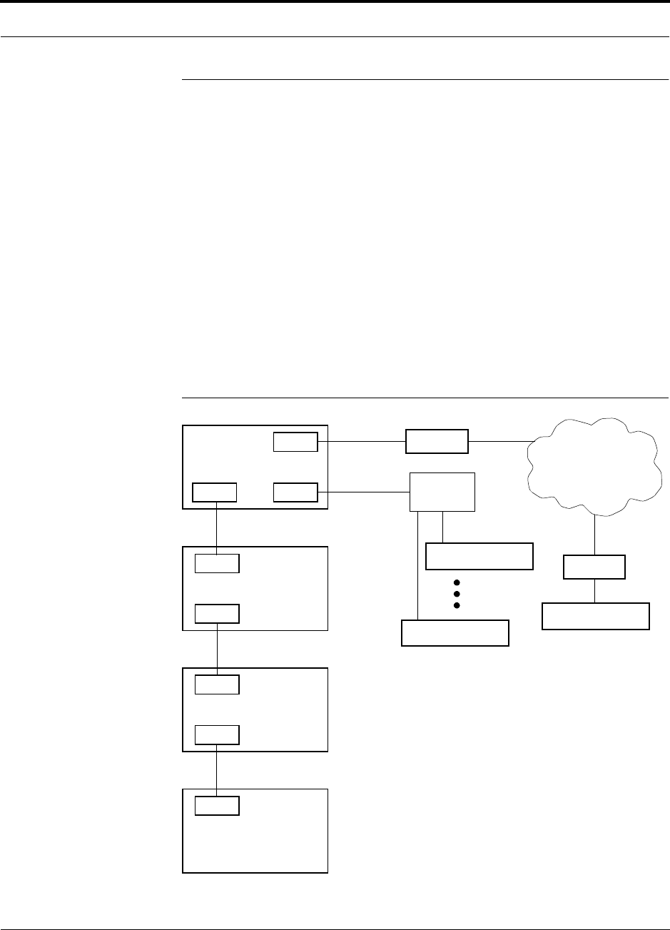
Main Hub monitors system status and communicates that status using the following
methods:
• Normally closed (NC) alarm contact closures can be tied to standard NC alarm
monitoring systems or directly to a base station for alarm monitoring.
• The Main Hub’s front panel serial port connects directly to a PC (for local access)
or to a modem (for remote access).
Figure 2-1 OA&M Communications
PSTN
RS-232
RS-232 Ethernet
PC/Laptop
running
Modem
Main Hub
Modem
Main Hub
TCP/IP
RS-232
ENET/232
Converter
Cat-5/6
RS-232
SC/APC
Main Hub
SC/APC
RJ-45
Expansion Hub
RJ-45
Remote Access Unit
Fiber
Main Hub
AdminManager
Or OpsConsole
AdminManager can only initiate
communications with a remotely
modem calls.
Use the OpsConsole for monitoring
and receiving communications from
installed system; it cannot receive
remotely installed systems.
InterReach™ Unison System Description PRELIMINARY
2-6 InterReach Unison User Guide and Reference Manual PN 8700-10
620003-0
2.4.1 Configuring, Maintaining, and Monitoring Unison Locally
Each Main Hub, Expansion Hub, and RAU in the system constantly monitors itself
and its downstream units for internal fault and warning conditions. The results of the
monitoring are stored in memory and compared against new results.
The Expansion Hubs monitor their RAUs and store their status in memory. The Main
Hub monitors its Expansion Hubs and stores their status and the status of the RAUs in
its memory. When a unit detects a change in status, a fault or warning is reported.
Faults are indicated locally by red status LEDs, and faults and warnings are reported
to the Main Hub and displayed on a PC/laptop, via the Main Hub’s serial port, that is
running the AdminManager software.
Using AdminManager locally, you can install a new system or new components,
change system parameters, and query system status. The following figure illustrates
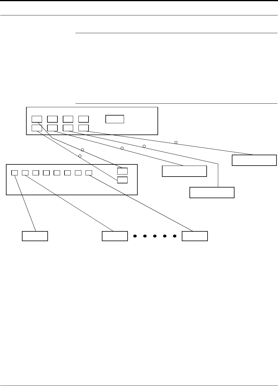
how the system reports its status to AdminManager.
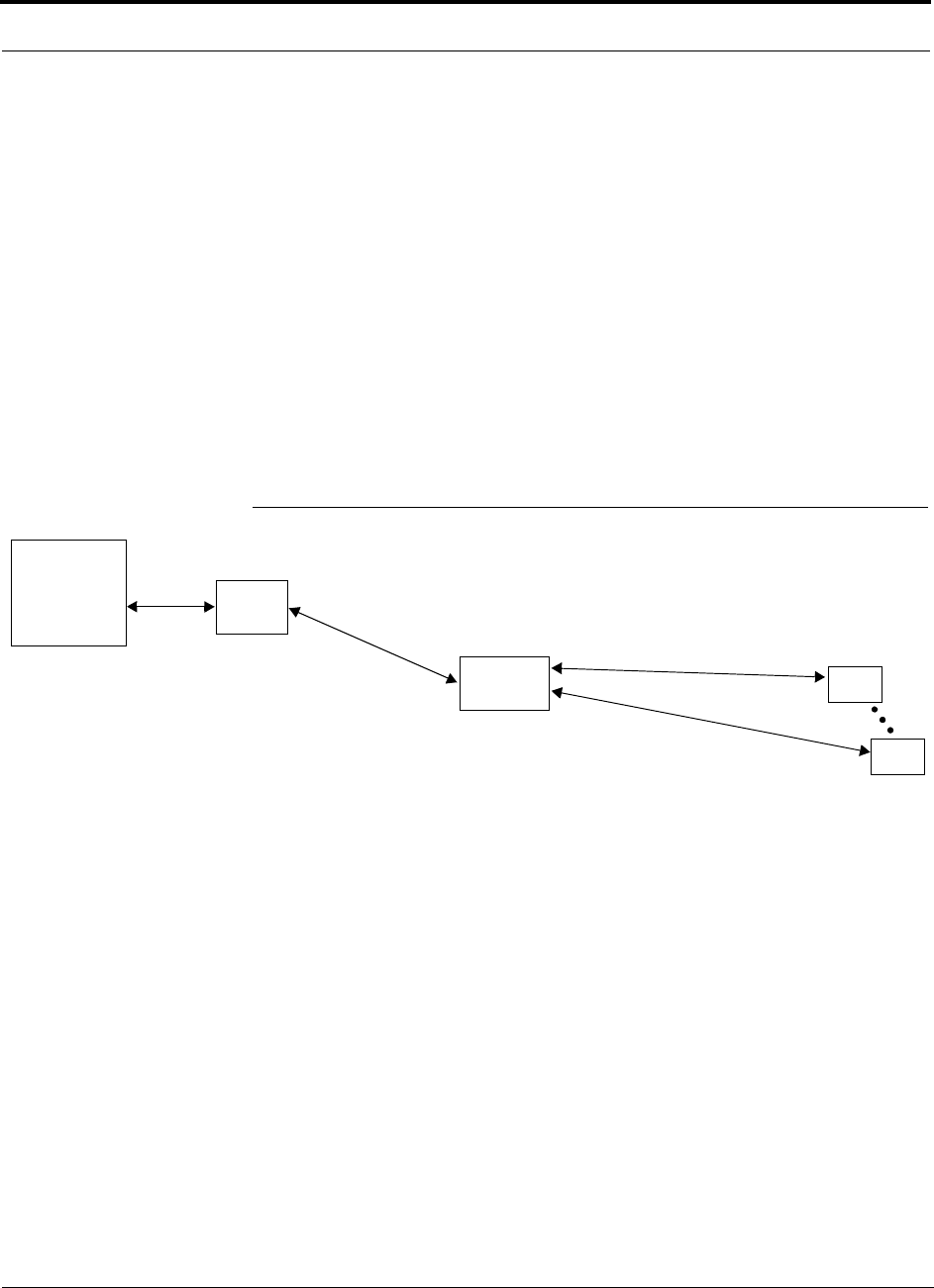
Figure 2-2 Local System Monitoring and Reporting
Main
Hub
Expansion
Hub
The Main Hub checks its own status and polls each of its
Expansion Hubs for their status, which includes RAU status.
The Expansion Hub checks its own status
and polls each of its RAUs for their status.
Each RAU reports its status to
the Expansion Hub.
• If a fault is detected, the
ALARM LED is red. If no fault
is detected, the LED is green.
• If a fault or warning condition
is detected, the information is
passed to the Expansion
Hub.
The Expansion Hub
receives status from
each of its RAUs and compares
it to previously stored status.
• LEDs on the front panel of the
Expansion Hub light red if a fault
is detected in itself or an RAU.
• If a fault or warning condition is
detected in the Expansion Hub
or an RAU, the information is
passed to the Main Hub.
The Main Hub receives
status of the Expansion Hubs
and each of their RAUs, and
compares it to previously
stored status.
• LEDs on the front panel of
the Main Hub light red if a
fault is detected in any unit.
• If a fault or warning condi-
tion is detected in any unit,
the Main Hub reports it to
the AdminManager.
PC/Laptop
running
AdminManager
Use the Admin-
Manager to query
units for their status
or get current warn-
ing and alarm con-
ditions.
RAU
RAU
PN 8700-10 Help Hot Line (U.S. only): 1-800-530-9960 2-7
620003-0
PRELIMINARY Monitoring and Maintaining Unison Remotely
2.4.2 Monitoring and Maintaining Unison Remotely
When monitoring the system remotely, any change of state within the system causes
the Main Hub to initiate an automatic call-out and report the system status to the
OpsConsole. If the host does not acknowledge the connection, the Main Hub issues
an automatic call-out every 15 minutes until an auto acknowledge or standard request
for status (initiated by the host) is received.
You can use AdminManager to query system status via a read-only Configuration &
Maintenance panel. You cannot change system parameters or configure system com-
ponents remotely with AdminManager. (Refer to Figure 2-1 on page 2-5.)
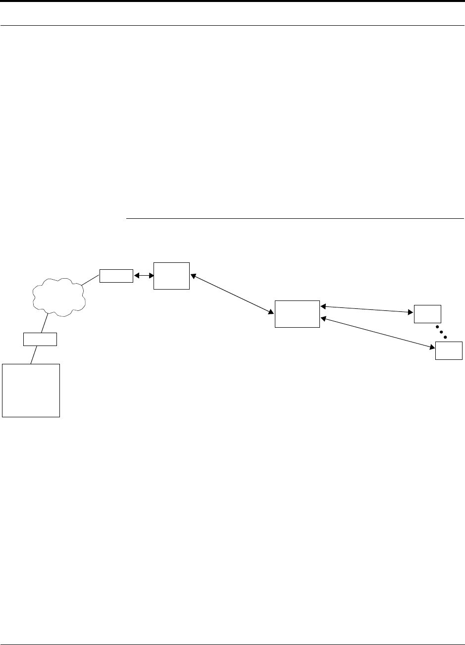
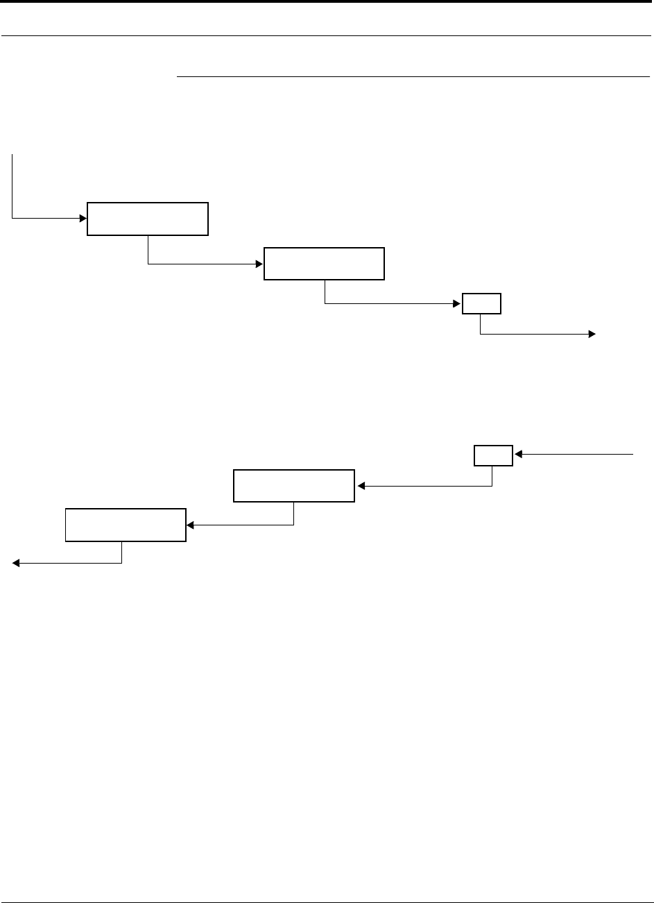
The following figure illustrates how the system reports its status to the OpsConsole.
Figure 2-3 Remote System Monitoring and Reporting
Refer to the OpsConsole User Guide, LGC Wireless part number 8701-10, for more
information about using the OpsConsole for system monitoring.
Expansion
Hub
The Expansion Hub checks its own status
and polls each of its RAUs for their status.
Each RAU reports its status to
the Expansion Hub.
• If a fault is detected, the
ALARM LED is red. If no fault
is detected, the LED is green.
• If a fault or warning condition
is detected, the information is
passed to the Expansion
Hub.
The Expansion Hub
receives status from
each RAU and compares
it to previously stored status.
• If a fault is detected, LEDs on
the front panel light red.
• If a fault or warning condition
is detected in the Expansion
Hub or an RAU, the informa-
tion is passed to the Main
Hub.
The Main Hub receives
status of Expansion Hub
and each RAU and com-
pares it to previously
stored status.
• If a fault is detected,
LEDs on the front panel
light red.
• If a fault or warning con-
dition is detected in any
unit, the Main Hub ini-
tiates a call to the
OpsConsole.
Use the OpsConsole to
remotely monitor and
maintain the system.
RAU
RAU
Modem
Modem
PSTN
Main
Hub
PC
running
OpsConsole
The Main Hub checks its own status and polls each of its
Expansion Hubs for their status, which includes RAU status.

InterReach™ Unison System Description PRELIMINARY
2-8 InterReach Unison User Guide and Reference Manual PN 8700-10
620003-0
2.4.3 Using Alarm Contact Closures
The DB-9 female connector on the rear panel of the Main Hub can be connected to a
local base station or to a daisy-chained series of Unison, LGCell, and/or MetroReach
Focus systems.
• When you connect MetroReach Focus or a BTS to Unison, the Unison Main Hub
is the output of the alarms (alarm source) and Focus is the input (alarm sense).
• When you connect LGCell to Unison, the Unison Main Hub is the input of the
alarms (alarm sense) and the LGCell is the output (alarm source).
Refer to Section 6.7 on page 6-34 for information on how to connect other equipment
to a Unison system for monitoring.
PN 8700-10 Help Hot Line (U.S. only): 1-800-530-9960 2-9
620003-0
PRELIMINARY System Connectivity
2.5 System Connectivity
The double star architecture of the Unison system, illustrated in the following figure,
provides excellent system scalability and reliability. The system requires only one
pair of fiber for 8 antenna points. This makes any system expansion, such as adding
an extra antenna for additional coverage, potentially as easy as pulling an extra
twisted pair (instead of pulling additional fiber).
Figure 2-4 Unison’s Double Star Architecture
Main Hub
RS-232
PORT 1 PORT 2 PORT 3 PORT 4
Expansion Hub Expansion Hub
Fiber
Expansion Hub
Expansion Hub
Cat-5/6Cat-5/6 Cat-5/6
up to 8 RAUs per Expansion Hub
RAU RAU RAU
InterReach™ Unison System Description PRELIMINARY
2-10 InterReach Unison User Guide and Reference Manual PN 8700-10
620003-0
2.6 System Operation
• Downlink (Base Station to Wireless Devices)
• Uplink (Wireless Devices to Base Station)
Main Hub
RAU
The Main Hub receives downlink RF signals
from a base station via coaxial cable
The Main Hub converts the RF signals to IF, then
to optical signals and sends them to Expansion
Hubs (up to four) via optical fiber cable.
The Expansion Hub converts the optical sig-
nals to electrical signals and sends them to
RAUs (up to eight) via Cat-5/6 cable.
The RAU converts the IF signals
to RF and sends them to passive
antennas via coaxial cable.
Expansion Hub
Main Hub
RAU
The Main Hub sends
uplink RF signals to a
base station via coaxial
cable
The Main Hub receives
the optical signals from
the Expansion Hubs (up
to four) via optical fiber
cables and converts
them to RF signals.
The Expansion Hub
receives the IF signals
from the RAUs (up to
eight) via Cat-5/6
cables and converts
them to optical signals.
The RAU receives uplink RF
signals from the passive
antenna via coaxial cable and
converts them to IF signals.
Expansion Hub

PN 8700-10 Help Hot Line (U.S. only): 1-800-530-9960 2-11
620003-0
PRELIMINARY System Specifications
2.7 System Specifications
2.7.1 Physical Specifications
Parameter Main Hub Expansion Hub Remote Antenna Unit
RF Connectors 2 N-type, female 8 shielded RJ-45, female
(Cat-5/6)
1 RJ-45, female (Cat-5/6)
1 SMA, male (coaxial)
External Alarm Connector
(contact closure)
1 9-pin D-sub, female — —
Serial Interface Connector 1 9-pin D-sub, male — —
Fiber Connectors 4 Pair, SC/APC 1 Pair, SC/APC —
LED Alarm and
Status Indicators
Unit Status (1 pair):
•Power
• Main Hub Status
Downstream Unit Status
(1 pair per fiber port):
•Link
•E-Hub/RAU
Unit Status (1 pair):
•Power
•E-Hub Status
Fiber Link Status (1 pair):
•DL Status
•UL Status
RAU/Link Status
(1 pair per RJ-45 port):
•Link
•RAU
Unit Status (1 pair):
•Link
•Alarm
AC Power (Volts) Rating: 100–240V, 0.5A,
50–60 Hz
Operating Range: 85–250V,
2.4–0.8A, 47–63 Hz
Rating: 115/230V, 5/2.5A,
50–60 Hz
Operating Range:
90–132V/170–250V
auto-ranging,
2.2–1.5A/1.2–0.8A, 47–63 Hz
—
DC Power (Volts) — — 36V
Power Consumption (W) 30 260 (includes 8 RAUs) 11
Enclosure Dimensions*
(height × width × depth)
*Excluding angle-brackets for 19'' rack mounting of hubs.
44.5 mm × 438 mm × 305 mm
(1.75 in. × 17.25 in. × 12 in.)
89 mm × 438 mm × 305 mm
(3.5 in. × 17.25 in. × 12 in.)
44 mm × 305 mm × 158 mm
(1.7 in. × 12 in. × 6.2 in.)
Weight < 3 kg
(< 6.5 lb)
< 5 kg
(< 11 lb)
< 1 kg
(< 2 lb)
MTBF 106,272 hours 78,998 hours 282,207 hours

InterReach™ Unison System Description PRELIMINARY
2-12 InterReach Unison User Guide and Reference Manual PN 8700-10
620003-0
2.7.2 Environmental Specifications
2.7.3 Operating Frequencies
Parameter Main Hub and Expansion Hub RAU
Operating Temperature 0° to +45°C (+32° to +113°F) –25° to +45°C (–13° to +113°F)
Non-operating Temperature –20° to +85°C (–4° to +185°F) –25° to +85°C (–13° to +185°F)
Operating Humidity; non-condensing 5% to 95% 5% to 95%
Freq.
Band Unison
Band Description
RF Passband
Downlink (MHz) Uplink (MHz)
PCS PCS1 A & D Band 1930–1950 1850–1870
PCS PCS2 D & B Band 1945–1965 1865–1885
PCS PCS3 B & E Band 1950–1970 1870–1890
PCS PCS4 E & F Band 1965–1975 1885–1895
PCS PCS5 F & C Band 1970–1990 1890–1910
DCS DCS1 DCS1 Band 1805–1842.5 1710–1747.5
DCS DCS2 DCS2 Band 1842.5–1880 1747.5–1785
DCS DCS3 DCS3 Band 1840–1875 1745–1780
Cellular CELL – 869–894 824–849
iDEN iDEN – 851–869 806–824
EGSM EGSM – 925–960 880–915
GSM GSM – 935–960 890–915
UMTS UMTS1 – 2110–2145 1920–1955
UMTS UMTS2 – 2125–2160 1935–1970
UMTS UMTS3 – 2135–2170 1945–1980

PN 8700-10 Help Hot Line (U.S. only): 1-800-530-9960 2-13
620003-0
PRELIMINARY RF End-to-End Performance
2.7.4 RF End-to-End Performance
Table 2-1 Cellular RF End-to-End Performance
Parameter Typical
Link
UL DL
Average gain with 75 m Cat-5/6 at 25°C (77°F)*
*System output gain: 0 to 15 dB, adjustable in 1 dB steps.
The gain of individual RAUs can be attenuated 0 to 10 dB, adjustable in one step.
15 dB
Uplink Ripple with 75 m Cat-5/6 3 dB
Downlink Ripple with 75 m Cat-5/6 2 dB
Output IP3 38 dBm
Input IP3†
†For two tones into one RAU, IP3 higher in other circumstances.
–16 dBm
Output 1 dB Compression Point 26 dBm
AMPS output power per carrier when 30 carriers are present 0.7 dBm
TDMA output power per carrier when 16 carriers are present 4.0 dBm
CDMA output power per carrier when 6 carriers are present 7.8 dBm
Noise Figure 1 MH-1 EH-8 RAUs 16 dB
Noise Figure 1 MH-4 EHs-32 RAUs 22 dB
Table 2-2 iDEN RF End-to-End Performance
Parameter Typical
Link
UL DL
Average gain with 75 m Cat-5/6 at 25°C (77°F)*
*System output gain: 0 to 15 dB, adjustable in 1 dB steps.
The gain of individual RAUs can be attenuated 0 to 10 dB, adjustable in one step.
15 dB
Uplink Ripple with 75 m Cat-5/6 3 dB
Downlink Ripple with 75 m Cat-5/6 2 dB
Output IP3 38 dBm
Input IP3 –16 dBm
Output 1 dB Compression Point 26 dBm
Output power per carrier when 6 carriers are present 6.4 dBm
Noise Figure 1 MH-1 EH-8 RAUs 17 dB
Noise Figure 1 MH-4 EHs-32 RAUs 23 dB

InterReach™ Unison System Description PRELIMINARY
2-14 InterReach Unison User Guide and Reference Manual PN 8700-10
620003-0
Table 2-3 GSM RF End-to-End Performance
Parameter Typical
Link
UL DL
Average gain with 75 m Cat-5/6 at 25°C (77°F)*
*System output gain: 0 to 15 dB, adjustable in 1 dB steps.
The gain of individual RAUs can be attenuated 0 to 10 dB, adjustable in one step.
15 dB
Uplink Ripple with 75 m Cat-5/6 3 dB
Downlink Ripple with 75 m Cat-5/6 2 dB
Output IP3 38 dBm
Input IP3 –16 dBm
Output 1 dB Compression Point 26 dBm
GSM output power per carrier when 12 carriers are present 5.0 dBm
Noise Figure 1 MH-1 EH-8 RAUs 17 dB
Noise Figure 1 MH-4 EHs-32 RAUs 23 dB
Table 2-4 EGSM RF End-to-End Performance
Parameter Typical
Link
UL DL
Average gain with 75 m Cat-5/6 at 25°C (77°F) *
*System output gain: 0 to 15 dB, adjustable in 1 dB steps.
The gain of individual RAUs can be attenuated 0 to 10 dB, adjustable in one step.
15 dB
Uplink Ripple with 75 m Cat-5/6 3 dB
Downlink Ripple with 75 m Cat-5/6 3 dB
Output IP3 38 dBm
Input IP3 –16 dBm
Output 1 dB Compression Point 26 dBm
GSM output power per carrier when 12 carriers are present 5.0 dBm
Noise Figure 1 MH-1 EH-8 RAUs 16 dB
Noise Figure 1 MH-4 EHs-32 RAUs 22 dB

PN 8700-10 Help Hot Line (U.S. only): 1-800-530-9960 2-15
620003-0
PRELIMINARY RF End-to-End Performance
Table 2-5 DCS RF End-to-End Performance
Parameter Typical
Link
UL DL
Average gain with 75 m Cat-5/6 at 25°C (77°F)*
*System output gain: 0 to 15 dB, adjustable in 1 dB steps.
The gain of individual RAUs can be attenuated 0 to 10 dB, adjustable in one step.
15 dB
Uplink Ripple with 75 m Cat-5/6 5.5 dB
Downlink Ripple with 75 m Cat-5/6 3 dB
Output IP3 36.5 dBm
Input IP3 –16 dBm
Output 1 dB Compression Point 24.5 dBm
GSM output power per carrier when 16 carriers are present 5.0 dBm
Noise Figure 1 MH-1 EH-8 RAUs 17 dB
Noise Figure 1 MH-4 EHs-32 RAUs 23 dB
Table 2-6 PCS RF End-to-End Performance
Parameter Typical
Link
UL DL
Average gain with 75 m Cat-5/6 at 25°C (77°F)*
*System output gain: 0 to 15 dB, adjustable in 1 dB steps.
The gain of individual RAUs can be attenuated 0 to 10 dB, adjustable in one step.
15 dB
Uplink Ripple with 75 m Cat-5/6 3 dB
Downlink Ripple with 75 m Cat-5/6 3 dB
Output IP3 36.5 dBm
Input IP3 –16 dBm
Output 1 dB Compression Point 24.5 dBm
TDMA output power per carrier when 16 carriers are present 4.0 dBm
GSM output power per carrier when 16 carriers are present 4.2 dBm
CDMA output power per carrier when 8 carriers are present 7.8 dBm
Noise Figure 1 MH-1 EH-8 RAUs 16 dB
Noise Figure 1 MH-4 EHs-32 RAUs 22 dB

InterReach™ Unison System Description PRELIMINARY
2-16 InterReach Unison User Guide and Reference Manual PN 8700-10
620003-0
Table 2-7 W-CDMA RF End-to-End Performance
Parameter Typical
Link
UL DL
Average gain with 75 m Cat-5/6 at 25°C (77°F) *
*System output gain: 0 to 15 dB, adjustable in 1 dB steps.
The gain of individual RAUs can be attenuated 0 to 10 dB, adjustable in one step.
15 dB
Uplink Ripple with 75 m Cat-5/6 3 dB
Downlink Ripple with 75 m Cat-5/6 3 dB
Output IP3 36.5 dBm
Input IP3 –12 dBm
Output 1 dB Compression Point 26 dBm
Output power per carrier when 7 carriers are present TBD
Noise Figure 1 MH-1 EH-8 RAUs 16 dB
Noise Figure 1 MH-4 EHs-32 RAUs 22 dB
PN 8700-10 InterReach Unison User Guide and Reference Manual 3-1
620003-0
PRELIMINARY
SECTION 3 Unison Main Hub
The Main Hub distributes downlink RF signals from a base station, repeater, or
MetroReach Focus system to up to four Expansion Hubs, which in turn distribute the
signals to up to 32 Remote Access Units. The Main Hub also combines uplink signals
from the Expansion Hubs for a base station or MetroReach Focus system.
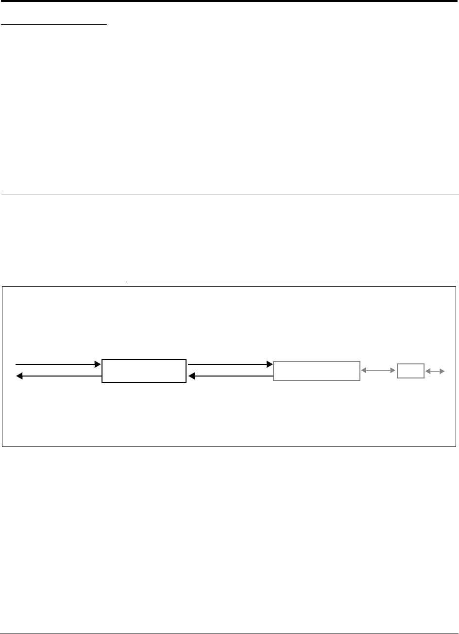
Figure 3-1 Main Hub in a Unison System
Unison Main Hub Unison Expansion Hub RAU
Downlink Path: The Main Hub receives downlink RF signals from a base station, repeater, or MetroReach Focus system
via coaxial cable. It converts the signals to optical and sends them to up to four Expansion Hubs via fiber optic cables.
The Main Hub also sends OA&M communication to the Expansion Hubs via the fiber optic cable. The Expansion Hubs, in
turn, communicate the OA&M information to the RAUs via Cat-5/6 cable.
Uplink Path: The Main Hub receives uplink optical signals from up to four Expansion Hubs via fiber optic cables. It converts
the signals to RF and sends them to a base station, repeater, or MetroReach Focus system via coaxial cable.
The Main Hub also receives status information from the Expansion Hubs and all RAUs via the fiber optic cable.
Downlink to Main Hub
Uplink from Main Hub
Downlink from Main Hub
Uplink to Main Hub
Unison Main Hub PRELIMINARY
3-2 InterReach Unison User Guide and Reference Manual PN 8700-10
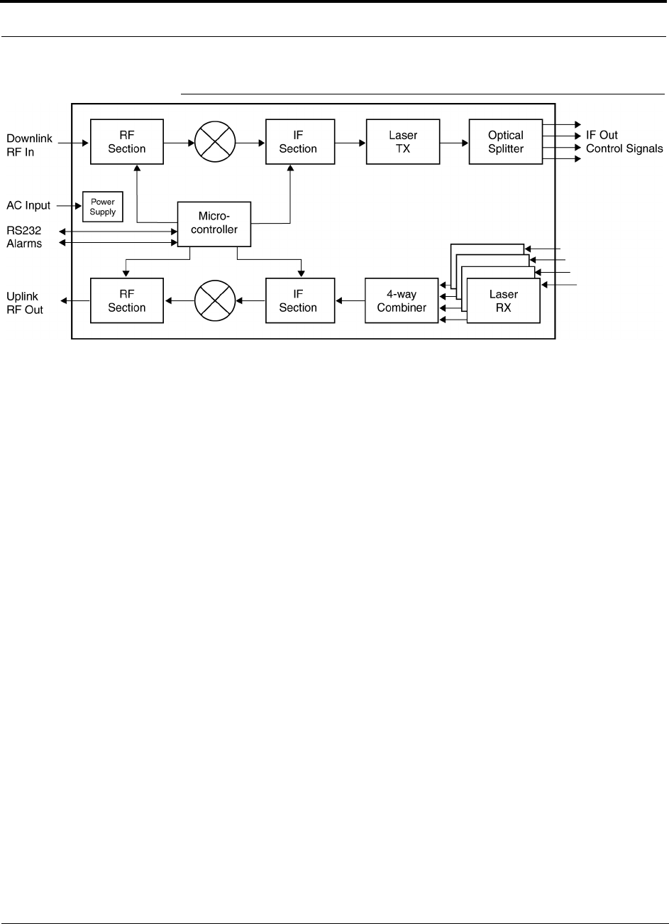
620003-0
Figure 3-2 Main Hub Block Diagram
PN 8700-10 Help Hot Line (U.S. only): 1-800-530-9960 3-3
620003-0
PRELIMINARY Main Hub Front Panel
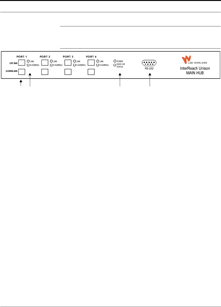
3.1 Main Hub Front Panel
Figure 3-3 Main Hub Front Panel
1. Four fiber optic ports (labeled PORT 1, PORT 2, PORT 3, PORT 4)
• One standard female SC/APC connector per port for MMF/SMF input (labeled
UPLINK)
• One standard female SC/APC connector per port for MMF/SMF output
(labeled DOWNLINK)
2. Four sets of fiber port LEDs (one set per port)
• One LED per port for port link status (labeled LINK)
• One LED per port for downstream unit status (labeled E-HUB/RAU)
3. One set of unit status LEDs
• One LED for unit power status (labeled POWER)
• One LED for unit status (labeled MAIN HUB STATUS)
4. One 9-pin D-sub male connector for system communication and diagnostics using
a PC/laptop (labeled RS-232)
1234
Unison Main Hub PRELIMINARY
3-4 InterReach Unison User Guide and Reference Manual PN 8700-10
620003-0
3.1.1 Optical Fiber Uplink/Downlink Ports
The optical fiber uplink/downlink ports transmit and receive optical signals between
the Main Hub and up to four Expansion Hub(s) using industry-standard SMF or
MMF cable. There are four fiber ports on the front panel of the Main Hub; one port
per Expansion Hub. Each fiber port has two female SC/APC connectors:
• Optical Fiber Uplink Connector
This connector (labeled UPLINK) is used to receive the uplink optical signals from
an Expansion Hub.
• Optical Fiber Downlink Connector
This connector (labeled DOWNLINK) is used to transmit the downlink optical sig-
nals to an Expansion Hub.
CAUTION: To avoid damaging the Main Hub’s fiber connector
ports, use only SC/APC fiber cable connectors.
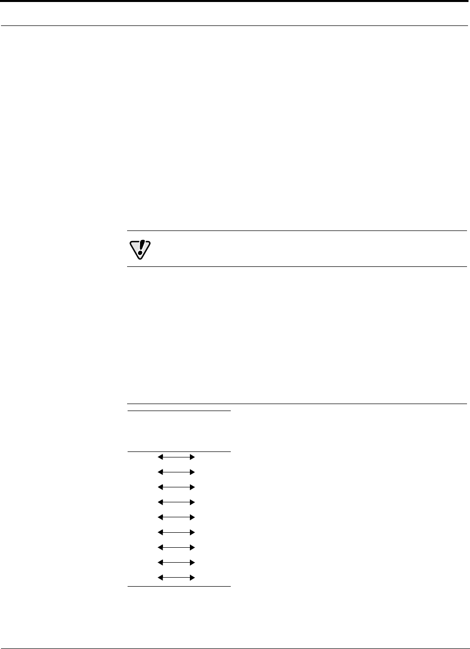
3.1.2 Communications RS-232 Serial Connector
Remote Monitoring
Use a standard serial cable to connect a modem to the 9-pin D-sub male serial con-
nector for remote monitoring or configuring. The cable typically has a DB-9 female
and a DB-25 male connector. The following figure shows the cable pinout.
Figure 3-4 Standard Serial Cable Pinout
DB-9
Connector
Pin
DB-25
Connector
Pin
1
2
3
4
5
6
7
8
9
8
3
2
20
7
6
4
5
22
PN 8700-10 Help Hot Line (U.S. only): 1-800-530-9960 3-5
620003-0
PRELIMINARY Communications RS-232 Serial Connector
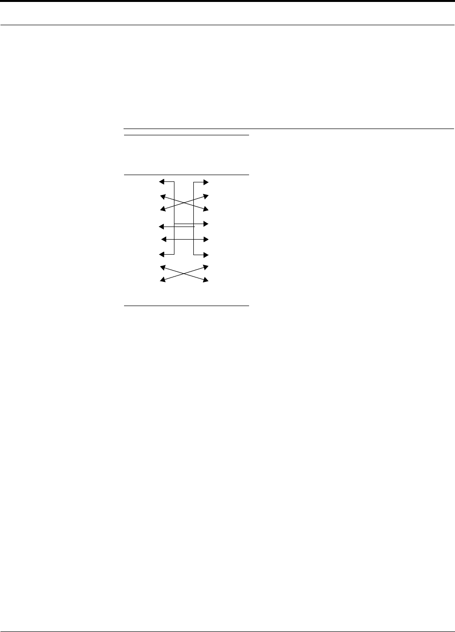
Local Monitoring
Use a null modem cable to connect a laptop or PC to the 9-pin D-sub male serial con-
nector for local monitoring or configuring. The cable typically has a DB-9 female
connector on both ends. The following figure shows the cable pinout.
Figure 3-5 Null Modem Cable Pinout
Note that for each connector, pins 1 and 6 are tied together and sent to pin 4 of the
opposite connector.
DB-9
Connector
Pin
DB-9
Connector
Pin
1
2
3
4
5
6
7
8
9
1
2
3
4
5
6
7
8
9
Unison Main Hub PRELIMINARY
3-6 InterReach Unison User Guide and Reference Manual PN 8700-10
620003-0
3.1.3 LED Indicators
The unit’s front panel LEDs indicate fault conditions and commanded or fault lockouts.
The LEDs do not indicate warnings or if the system test has not been performed. Use
the LEDs as a go/no go test or as a backup when you are not using AdminManager.
Upon power up, the Main Hub goes through a five-second test to check the LED
lamps. During this time, the LEDs blink through the states shown in Table 3-2, letting
you visually verify that the LED lamps and the firmware are functioning properly.
NOTE: Refer to Section 10 for troubleshooting using the LEDs.
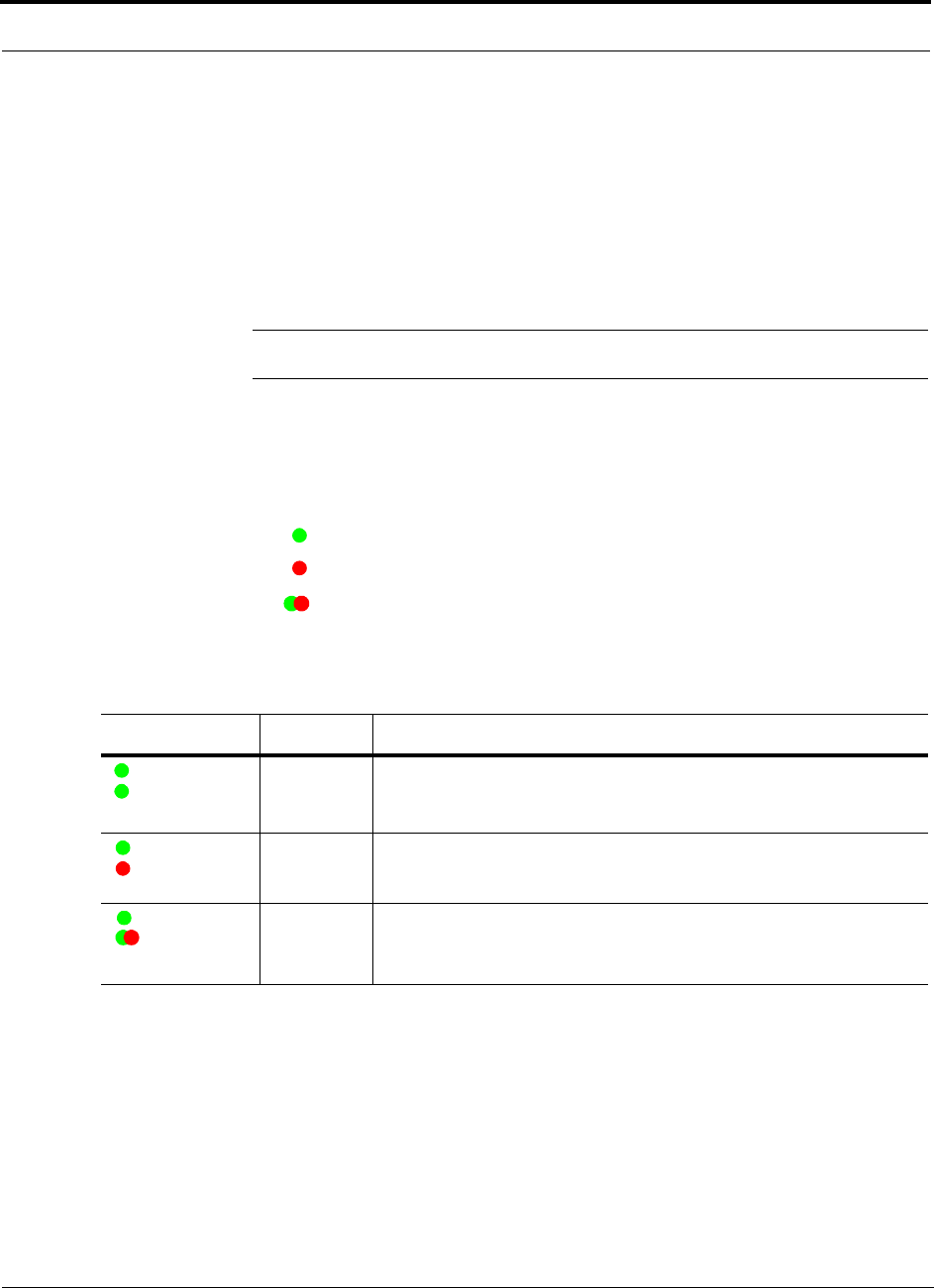
Unit Status LEDs
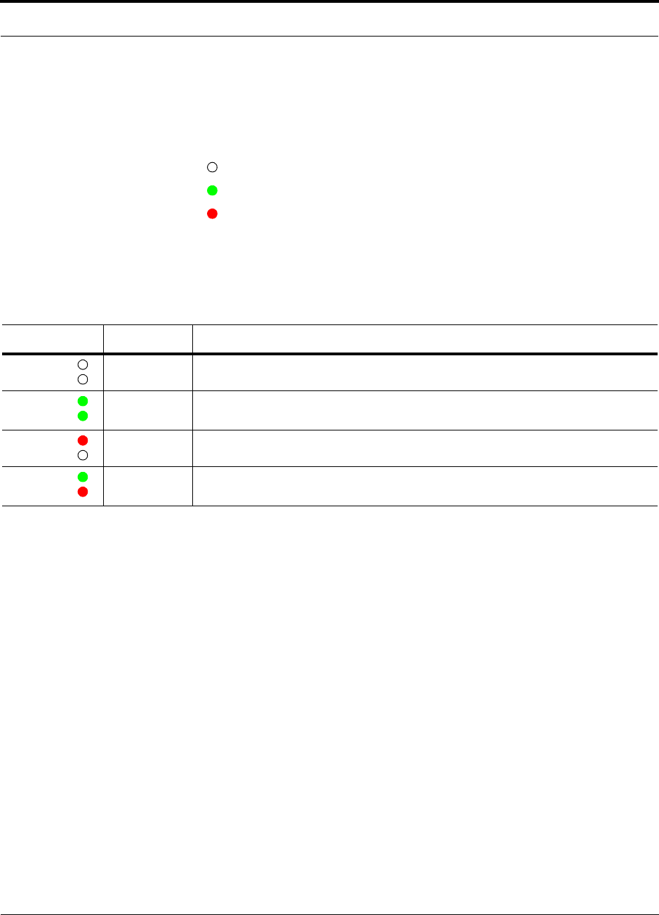
The Main Hub status LEDs can be in one of three states, as shown in Table 3-1.
These LEDs can be:
steady green
steady red
blinking green/red (alternating green/red)
There is no off state when the unit’s power is on.
Table 3-1 Main Hub Status LED States
LED State Indicates
Green
Green
• Main Hub is connected to power
• Main Hub is not reporting a fault; but the system test may need to be
performed or a warning condition could exist
Green
Red
• Main Hub is connected to power
• Main Hub is reporting a fault or lockout condition
Green
Alternating
Green/Red
• Main Hub is connected to power
• Main Hub input signal level too high
POWER
MAIN HUB
STATUS
POWER
MAIN HUB
STATUS
POWER
MAIN HUB
STATUS
PN 8700-10 Help Hot Line (U.S. only): 1-800-530-9960 3-7
620003-0
PRELIMINARY LED Indicators
Port LEDs
The Main Hub has one pair of fiber port LEDs for each of the four Expansion Hub
ports. The LED pairs can be in one of four states, as shown in the following table, in a
combination of the following:
off
steady green
steady red
The port LEDs indicate the status of the Expansion Hub and RAUs; however, they do
not indicate which particular unit is having a problem (i.e., the Expansion Hub vs.
one of the RAUs).
Table 3-2 Main Hub Port LED States
LED State Indicates
Off
Off
• Expansion Hub not connected
Green
Green
• Expansion Hub connected, communications normal
• No faults from Expansion Hub or any connected RAU
Red
Off
• Loss of communications with Expansion Hub
Green
Red
• Expansion Hub connected
• Fault or lockout reported by Expansion Hub or any connected RAU
LINK
E-HUB/RAU
LINK
E-HUB/RAU
LINK
E-HUB/RAU
LINK
E-HUB/RAU
Unison Main Hub PRELIMINARY
3-8 InterReach Unison User Guide and Reference Manual PN 8700-10
620003-0
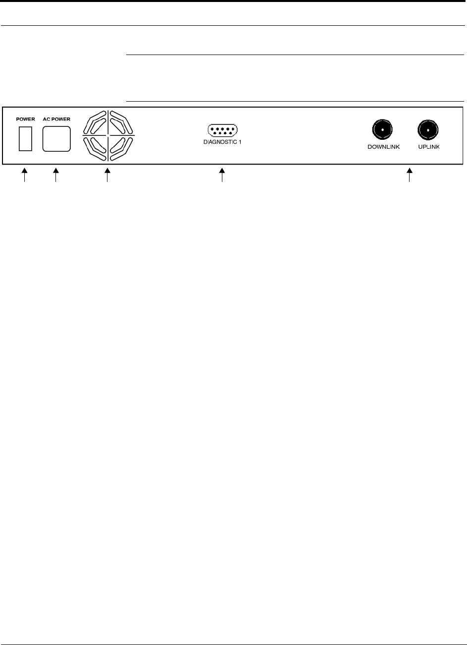
3.2 Main Hub Rear Panel
Figure 3-6 Main Hub Rear Panel
1. Power on/off switch
2. AC power cord connector
3. Fan exhaust vent
4. One 9-pin D-sub female connector for contact closure monitoring (labeled
DIAGNOSTIC 1)
5. Two N-type, female connectors:
• Downlink (labeled DOWNLINK)
• Uplink (labeled UPLINK)
1 2 3 4 5

PN 8700-10 Help Hot Line (U.S. only): 1-800-530-9960 3-9
620003-0
PRELIMINARY Main Hub Rear Panel Connectors
3.2.1 Main Hub Rear Panel Connectors
3.2.1.1 N-type Female Connectors
There are two N-type female connectors on the rear panel of the Main Hub:
•The
UPLINK connector transmits uplink RF signals to a repeater, local base sta-
tion, or MetroReach Focus system.
•The
DOWNLINK connector receives downlink RF signals from a repeater, local
base station, or MetroReach Focus system.
3.2.1.2 9-pin D-sub Connector
The 9-pin D-sub connector (labeled DIAGNOSTIC 1) provides contact closure for
major error and minor error system alarm monitoring.
The following table lists the function of each pin on the 9-pin D-sub connector. Pin
locations are labeled on the figure.
This interface can either generate contact alarms or sense a single external alarm con-
tact.
Pin Function
1 Ground / Alarm Input
2 Reserved
3 Reserved
4 Minor Error (positive connection)
5 Minor Error (negative connection)
6 DC Ground (common)
7 Major Error (positive connection)
8 Alarm Input
9 Major Error (negative connection)

Unison Main Hub PRELIMINARY
3-10 InterReach Unison User Guide and Reference Manual PN 8700-10
620003-0
3.3 Faults and Warnings
The Main Hub monitors and reports changes in system performance to:
• Ensure that Expansion Hubs and Remote Access Units are connected and function-
ing properly.
• Ensure that the fiber receivers, amplifiers, and IF/RF path in the Main Hub are
functioning properly.
The Main Hub periodically polls attached Expansion Hubs and their Remote Access
Units for status. Both fault and warning conditions are reported to a connected
PC/laptop that is running the AdminManager software or to the optional remote
OpsConsole. Only faults are indicated by LEDs.
The faults and warnings that the Main Hub is responsible for monitoring and report-
ing are listed in Section 10.

PN 8700-10 Help Hot Line (U.S. only): 1-800-530-9960 3-11
620003-0
PRELIMINARY Main Hub Specifications
3.4 Main Hub Specifications
Table 3-3 Main Hub Specifications
Specification Description
Enclosure Dimensions (H × W × D): 44.5 mm × 438 mm × 305 mm
(1.75 in. × 17.25 in. × 12 in.)
Weight < 3 kg (< 6.5 lb)
Operating Temperature 0° to +45°C (+32° to +113°F)
Non-operating Temperature –20° to +85°C (–4° to +185°F)
Operating Humidity, non-condensing 5% to 95%
External Alarm Connector
(contact closure)
1 9-pin D-sub, female
Serial Interface Connector 1 9-pin D-sub, male
Fiber Connectors 4 Pair, SC/APC
RF Connectors 2 N-type, female
LED Fault and Status Indicators Unit Status (1 pair):
•Power
• Main Hub Status
Downstream Unit/Link Status (1 pair per fiber port):
•Link
•E-Hub/RAU
AC Power Rating: 100–240V, 0.5A, 50–60 Hz
Operating Range: 85–250V, 2.4–0.8A, 47–63 Hz
Power Consumption (W) 30
MTBF 106,272 hours

Unison Main Hub PRELIMINARY
3-12 InterReach Unison User Guide and Reference Manual PN 8700-10
620003-0
PN 8700-10 InterReach Unison User Guide and Reference Manual 4-1
620003-0
PRELIMINARY
SECTION 4 Unison Expansion Hub
The Expansion Hub interfaces between the Main Hub and the Remote Access Unit(s)
by converting optical signals to electrical signals. It also supplies the DC power to
operate the Remote Access Unit(s).
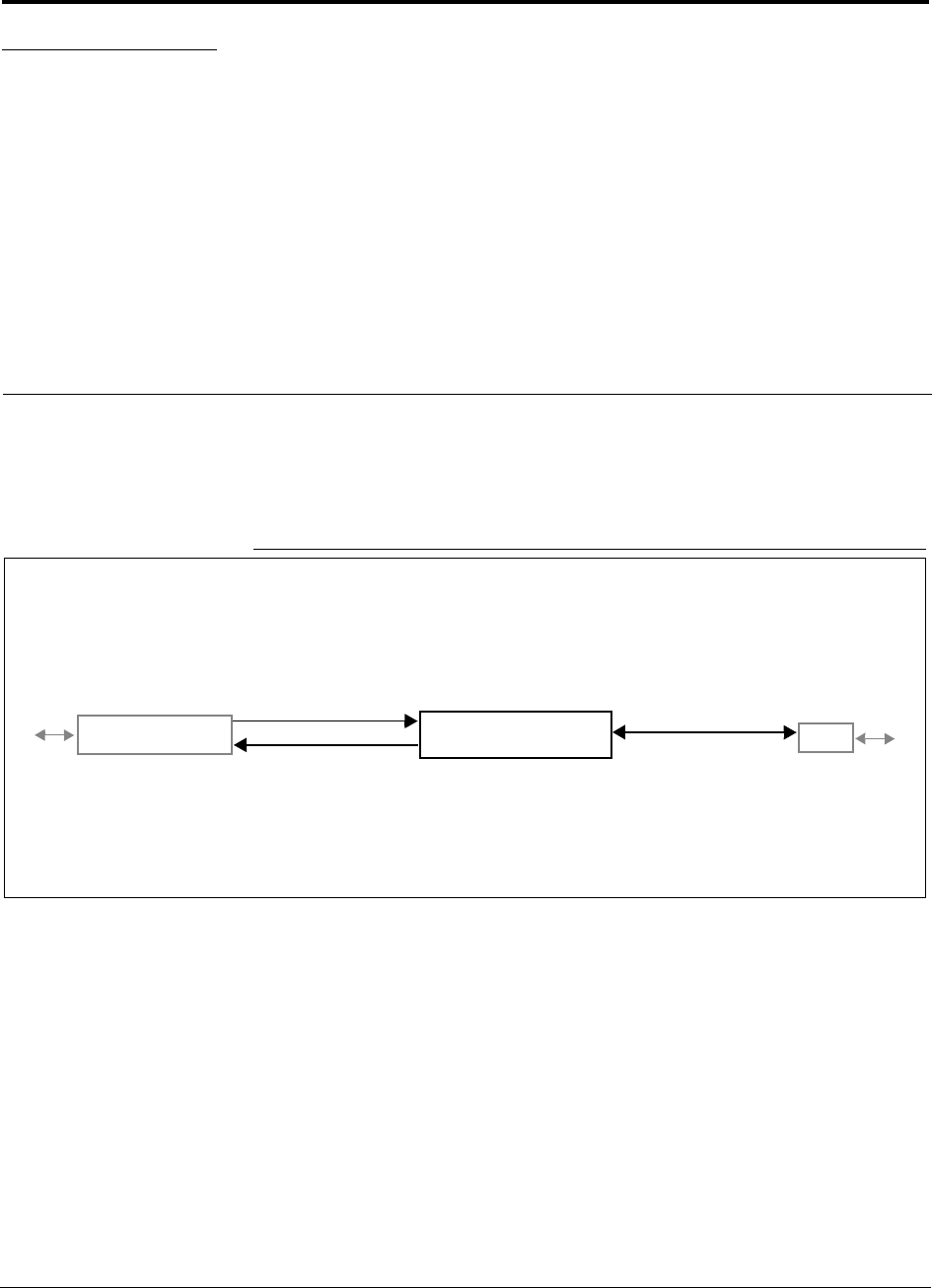
Figure 4-1 Expansion Hub in a Unison System
Unison Expansion Hub
Unison Main Hub RAU
Downlink Path: The Expansion Hub receives downlink optical signals from the Main Hub via fiber optic cable. It converts
the signals to electrical and sends them to up to eight Remote Access Units (RAUs) via Cat-5/6 cables.
Also, the Expansion Hub receives configuration information from the Main Hub via the fiber optic cable and relays configu-
ration information to the RAUs via the Cat-5/6 cable.
Uplink Path: The Expansion Hub receives uplink IF signals from up to eight RAUs via Cat-5/6 cables. It converts the sig-
nals to optical and sends them to a Main Hub via fiber optic cable.
Also, the Expansion Hub receives RAU status information via the Cat-5/6 cable and sends it and its own status information
to the Main Hub via the fiber optic cable.
Downlink to Expansion Hub
Uplink from Expansion Hub
Downlink from Expansion Hub
Uplink to Expansion Hub
Unison Expansion Hub PRELIMINARY
4-2 InterReach Unison User Guide and Reference Manual PN 8700-10
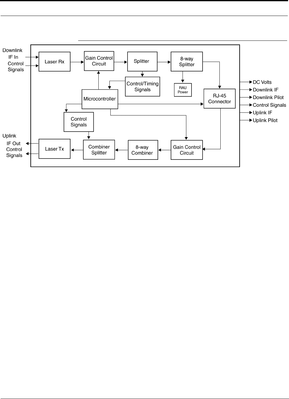
620003-0
Figure 4-2 Expansion Hub Block Diagram
PN 8700-10 Help Hot Line (U.S. only): 1-800-530-9960 4-3
620003-0
PRELIMINARY Expansion Hub Front Panel
4.1 Expansion Hub Front Panel
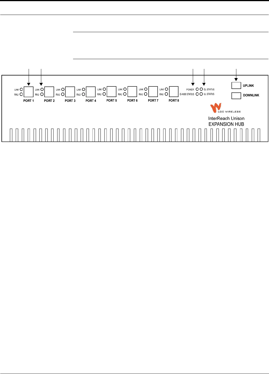
Figure 4-3 Expansion Hub Front Panel
1. Eight standard Cat-5/6 ScTP cable RJ-45 connectors (labeled PORT 1, 2, 3, 4, 5, 6,
7, 8)
2. Eight sets of RJ-45 port LEDs (one set per port)
• One LED per port for link status (labeled LINK)
• One LED per port for downstream unit status (labeled RAU)
3. One set of unit status LEDs
• One LED for unit power status (labeled POWER)
• One LED for unit status (labeled E-HUB STATUS)
4. One set of fiber connection status LEDs
• One LED for fiber downlink status (labeled DL STATUS)
• One LED for fiber uplink status (labeled UL STATUS)
5. One fiber optic port which has two connectors
• One standard female SC/APC connector for MMF/SMF input (labeled UPLINK)
• One standard female SC/APC connector for MMF/SMF output (labeled DOWN-
LINK)
1 2 3 4 5

Unison Expansion Hub PRELIMINARY
4-4 InterReach Unison User Guide and Reference Manual PN 8700-10
620003-0
4.1.1 RJ-45 Connectors
The eight RJ-45 connectors on the Expansion Hub are for the Cat-5/6 ScTP cable that
is used to transmit and receive signals to and from RAUs. Use shielded RJ-45 con-
nectors on the Cat-5/6 cable.
The Cat-5/6 cable also delivers DC electrical power to the RAUs. The Expansion
Hub’s DC voltage output is 36V DC nominal. A current limiting circuit is used to
protect the Expansion Hub if any port draws excessive power.
4.1.2 Optical Fiber Uplink/Downlink Connectors
The optical fiber uplink/downlink port transmits and receives optical signals between
the Expansion Hub and the Main Hub using industry-standard SMF or MMF cable.
The fiber port has two female SC/APC connectors:
• Optical Fiber Uplink Connector
This connector (labeled UPLINK) is used to transmit (output) uplink optical signals
to the Main Hub.
• Optical Fiber Downlink Connector
This connector (labeled DOWNLINK) is used to receive (input) downlink optical sig-
nals from the Main Hub.
CAUTION: To avoid damaging the Expansion Hub’s fiber con-
nector port, use only SC/APC fiber cable connectors.
PN 8700-10 Help Hot Line (U.S. only): 1-800-530-9960 4-5
620003-0
PRELIMINARY LED Indicators
4.1.3 LED Indicators
The unit’s front panel LEDs indicate fault conditions and commanded or fault lockouts.
The LEDs do not indicate warnings or if the system test has not been performed. Use
the LEDs as a go/no go test or as a backup when you are not using AdminManager.
Upon power up, the Expansion Hub goes through a five-second test to check the LED
lamps. During this time, the LEDs blink through the states shown in Table 4-2, letting
you visually verify that the LED lamps and the firmware are functioning properly.
NOTE: Refer to Section 10 for troubleshooting using the LEDs.
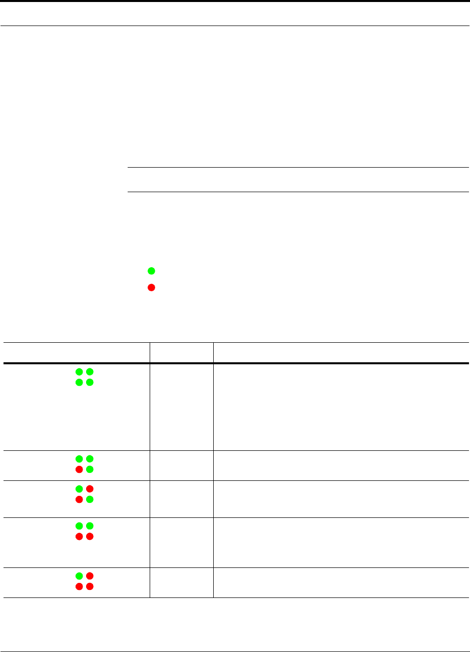
Unit Status and DL/UL Status LEDs
The Expansion Hub unit status and DL/UL status LEDs can be in one of five states,
as shown in the following table. These LEDs can be:
steady green
steady red
There is no off state when the unit’s power is on.
Table 4-1 Expansion Hub Unit Status and DL/UL Status LED States
LED State Indicates
Green / Green
Green / Green
• Expansion Hub is connected to power
• Expansion Hub is not reporting a fault or lockout; but the system
test may need to be performed or a warning condition could exist
• Optical power in is above minimum (Main Hub is connected)
although the cable length may be longer than recommended
maximum
• Optical power out (uplink laser) is normal
Green / Green
Red / Green
• Expansion Hub is reporting a fault or commanded lockout, but
optical power in and out are normal
Green / Red
Red / Green
• Fault condition detected, optical power in is below minimum.
(Main Hub is not connected, is not powered, or Main Hub’s DL
laser has failed.)
Green / Green
Red / Red
• Expansion Hub is reporting a fault condition
• Optical power in is normal, optical power out is below minimum
(Expansion Hub uplink laser has failed; unable to communicate
with Main Hub)
Green / Red
Red / Red
• No downlink or uplink: replace Expansion Hub
POWER
E-HUB STATUS DL STATUS
UL STATUS
POWER
E-HUB STATUS DL STATUS
UL STATUS
POWER
E-HUB STATUS DL STATUS
UL STATUS
POWER
E-HUB STATUS DL STATUS
UL STATUS
POWER
E-HUB STATUS DL STATUS
UL STATUS
Unison Expansion Hub PRELIMINARY
4-6 InterReach Unison User Guide and Reference Manual PN 8700-10
620003-0
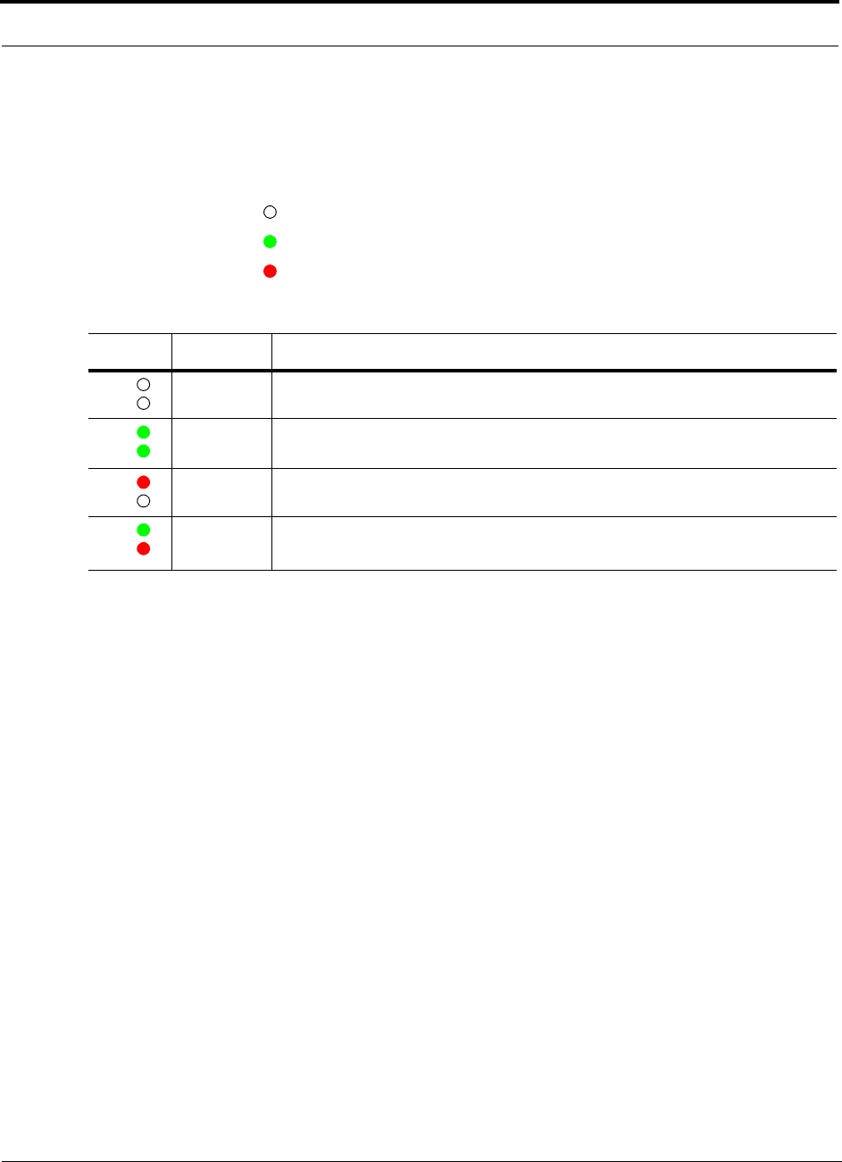
Port LEDs
The Expansion Hub has one pair of port LEDs for each of the eight RJ-45 ports. The
port LEDs can be in one of four states, as shown in the following table. These LEDs
can be:
off
steady green
steady red
Table 4-2 Expansion Hub Port LED States
LED State Indicates
Off
Off
• RAU is not connected
Green
Green
• RAU is connected
• No faults from RAU
Red
Off
• Loss of communications to RAU
Green
Red
• RAU is connected
• Fault/lockout condition reported by RAU
LINK
RAU
LINK
RAU
LINK
RAU
LINK
RAU
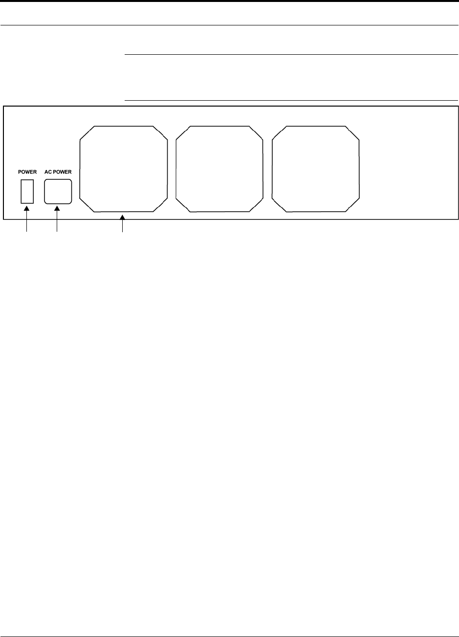
PN 8700-10 Help Hot Line (U.S. only): 1-800-530-9960 4-7
620003-0
PRELIMINARY Expansion Hub Rear Panel
4.2 Expansion Hub Rear Panel
Figure 4-4 Expansion Hub Rear Panel
1. Power on/off switch
2. AC power cord connector
3. Three air exhaust vents
1 2 3

Unison Expansion Hub PRELIMINARY
4-8 InterReach Unison User Guide and Reference Manual PN 8700-10
620003-0
4.3 Faults and Warnings
The Main Hub periodically polls attached Expansion Hubs and their Remote Access
Units for status. Both fault and warning conditions are reported to a connected
PC/laptop that is running the AdminManager software or to the optional remote
OpsConsole. Only faults are indicated by LEDs.
The faults and warnings that the Expansion Hub is responsible for monitoring and
Reporting are listed in Section 10.

PN 8700-10 Help Hot Line (U.S. only): 1-800-530-9960 4-9
620003-0
PRELIMINARY Expansion Hub Specifications
4.4 Expansion Hub Specifications
Table 4-3 Expansion Hub Specifications
Specification Description
Enclosure Dimensions (H × W × D) 89 mm × 438 mm × 305 mm
(3.5 in. × 17.25 in. × 12 in.)
Weight < 5 kg (< 11 lb)
Operating Temperature 0° to +45°C (+32° to +113°F)
Non-operating Temperature –20° to +85°C (–4° to +185°F)
Operating Humidity, non-condensing 5% to 95%
Cat-5/6 Connectors 8 shielded RJ-45, female (Cat-5/6)
Fiber Connectors 1 Pair, SC/APC
LED Alarm and Status Indicators Unit Status (1 pair):
•Power
• E-Hub Status
Fiber Link Status (1 pair):
•DL Status
•UL Status
RAU/Link Status (1 pair per RJ-45 port):
•Link
•RAU
AC Power (Volts) (47–63 Hz) Rating: 115/230V, 5/2.5A, 50–60 Hz
Operating Range: 90–132V/170–250V auto-ranging,
2.2–1.5A/1.2–0.8A, 47–63 Hz
Power Consumption (W) 260 (includes 8 RAUs)
MTBF 78,998 hours

Unison Expansion Hub PRELIMINARY
4-10 InterReach Unison User Guide and Reference Manual PN 8700-10
620003-0
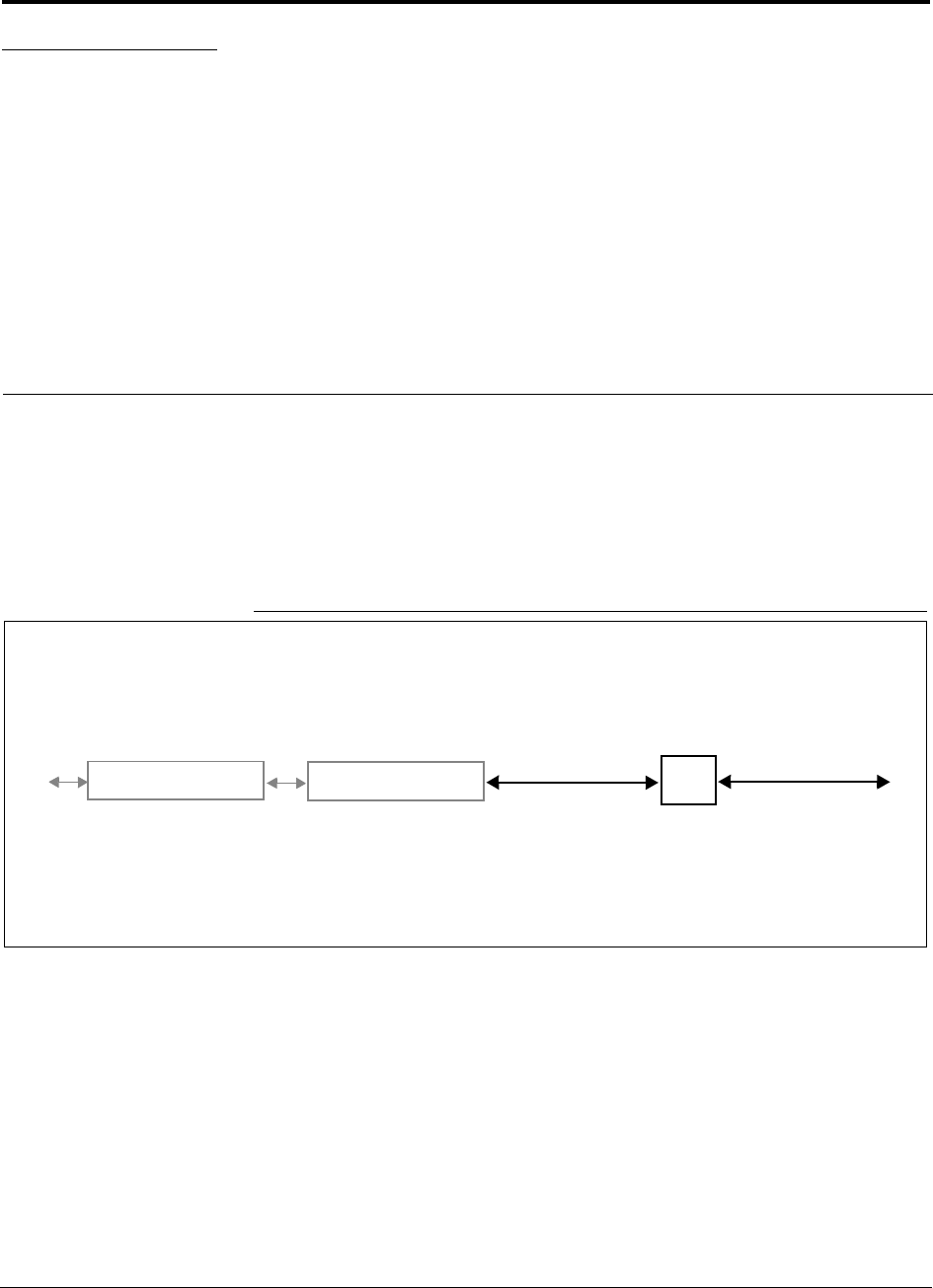
PN 8700-10 InterReach Unison User Guide and Reference Manual 5-1
620003-0
PRELIMINARY
SECTION 5 Unison Remote Access Unit
The Remote Access Unit (RAU) is an active transceiver that connects to an Expan-
sion Hub using industry-standard Cat-5/6 ScTP cable. The cable also delivers electri-
cal power to the RAU.
An RAU passes RF signals between an Expansion Hub and an attached passive
antenna where the signals are transmitted to wireless devices.
Figure 5-1 Remote Access Unit in a Unison System
Unison Expansion Hub RAU
Downlink Path: The RAU receives downlink IF signals from an Expansion Hub via Cat-5/6 cable. It converts the signals to
RF and sends them to a passive RF antenna via coaxial cable.
Also, the RAU receives configuration information from the Main Hub via the Cat-5/6 cable.
Uplink Path: The RAU receives uplink RF signals from a passive RF antenna via coaxial cable. It converts the signals to IF
and sends them to an Expansion Hub via Cat-5/6 cable.
Also, the RAU sends its status information to the Expansion Hub via the Cat-5/6 cable.
Downlink to RAU
Uplink from RAU
Unison Main Hub Downlink to antenna
Uplink from antenna
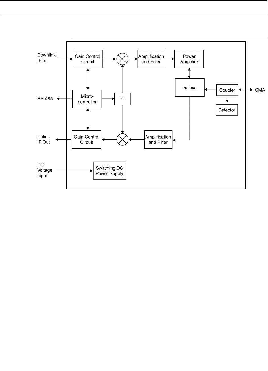
Unison Remote Access Unit PRELIMINARY
5-2 InterReach Unison User Guide and Reference Manual PN 8700-10
620003-0
Figure 5-2 Remote Access Unit Block Diagram
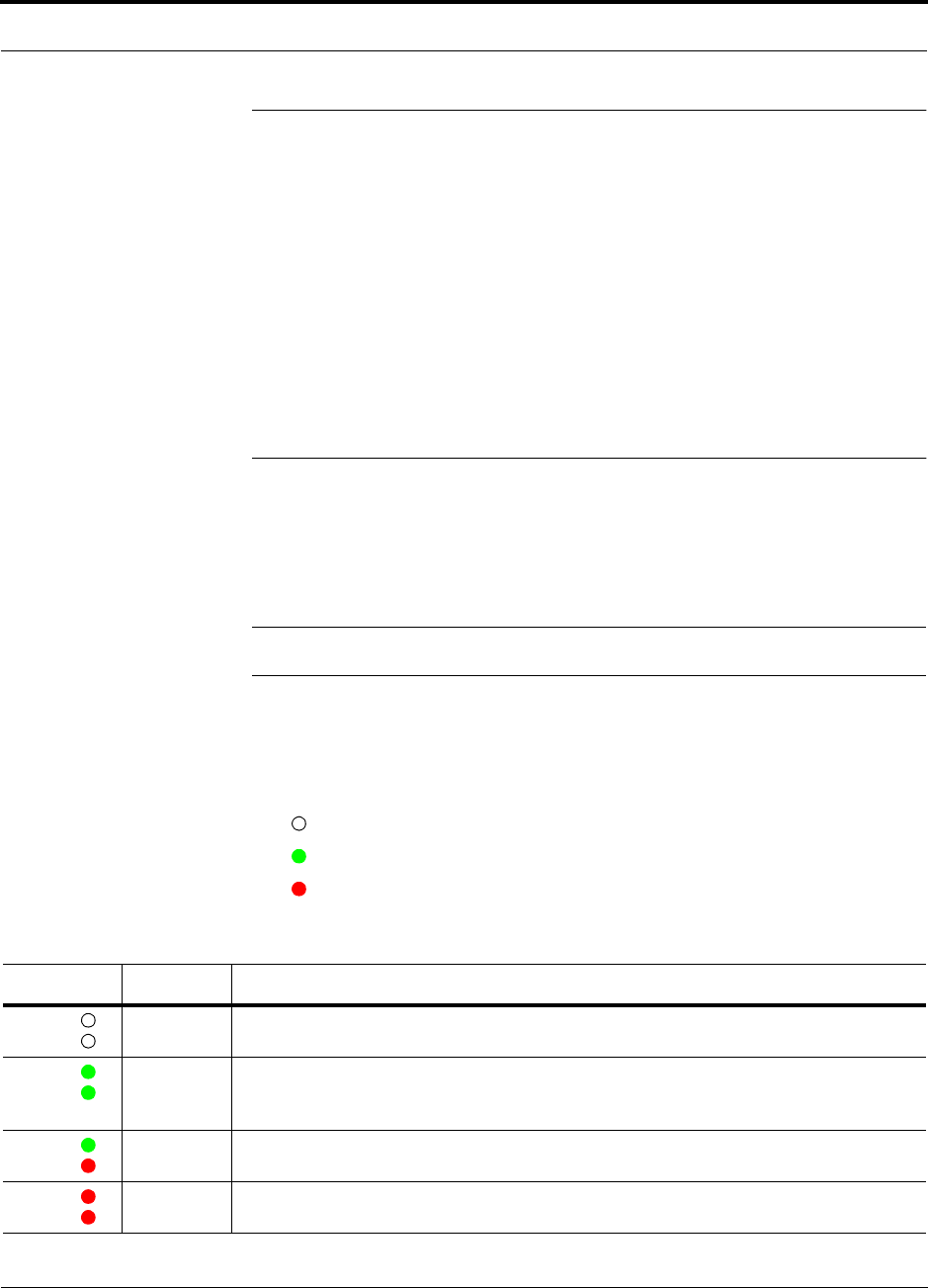
PN 8700-10 Help Hot Line (U.S. only): 1-800-530-9960 5-3
620003-0
PRELIMINARY Remote Access Unit Connectors
5.1 Remote Access Unit Connectors
5.1.1 SMA Connector
The RAU has one female SMA connector. The connector is a duplexed RF input/out-
put port that connects to a standard passive antenna using coaxial cable.
5.1.2 RJ-45 Port
The RAU has one RJ-45 port that connects it to an Expansion Hub using Cat-5/6
ScTP cable. Use shielded RJ-45 connectors on the Cat-5/6 cable.
5.2 LED Indicators
Upon power up, the RAU goes through a two-second test to check the LED lamps.
During this time, the LEDs blink through the states shown in Table 5-1, letting you
visually verify that the LED lamps and the firmware are functioning properly.
NOTE: Refer to Section 10 for troubleshooting using the LEDs.
Status LEDs
The RAU status LEDs can be in one of four states, as shown in the following table.
These LEDs can be:
off
steady green
steady red
Table 5-1 Remote Access Unit LED States
LED State Indicates
Off
Off
• RAU is not receiving DC power
Green
Green
• RAU is powered and is not indicating a fault condition. Communication with Expansion
Hub is normal; but the system test may need to be performed or a warning condition could
exist (use AdminManager to determine)
Green
Red
• RAU is indicating a fault or lockout condition, but communication with the Expansion Hub
is normal
Red
Red
• RAU is reporting a fault or lockout condition, and it is not able to communicate with the
Expansion Hub
LINK
ALARM
LINK
ALARM
LINK
ALARM
LINK
ALARM

Unison Remote Access Unit PRELIMINARY
5-4 InterReach Unison User Guide and Reference Manual PN 8700-10
620003-0
5.3 Faults and Warnings
The Main Hub periodically polls attached Expansion Hubs and their Remote Access
Units for status. Both faults and warning conditions are reported to a connected
PC/laptop that is running the AdminManager software, or to the optional remote
OpsConsole. Only faults are indicated by LEDs.
The faults and warnings that the RAU is responsible for monitoring and reporting are
listed in Section 10.

PN 8700-10 Help Hot Line (U.S. only): 1-800-530-9960 5-5
620003-0
PRELIMINARY Remote Access Unit Specifications
5.4 Remote Access Unit Specifications
Table 5-2 Remote Access Unit Specifications
Specification Description
Dimensions (H × W × D) 44 mm × 305 mm × 158 mm
(1.7 in. × 12 in. × 6.2 in.)
Weight < 1 kg (< 2 lb)
Operating Temperature –25° to +45°C (–13° to +113°F)
Non-operating Temperature –25° to +85°C (–13° to +185°F)
Operating Humidity, non-condensing 5% to 95%
RF Connectors 1 RJ-45, female (Cat-5/6)
1 SMA, male (coaxial)
LED Alarm and Status Indicators Unit Status (1 pair): • Link • Alarm
Maximum Heat Dissipation (W) 11
MTBF 282,207 hours

Unison Remote Access Unit PRELIMINARY
5-6 InterReach Unison User Guide and Reference Manual PN 8700-10
620003-0

PN 8700-10 InterReach Unison User Guide and Reference Manual 6-1
620003-0
PRELIMINARY
SECTION 6 Installing Unison Components
6.1 Installation Requirements
6.1.1 Component Location Requirements
Unison components are intended to be installed in indoor locations only.
6.1.2 Cable and Connector Requirements
The Unison equipment operates over standard Category 5 or 6 (Cat-5/6) screened
twisted pair (ScTP) and industry-standard single-mode fiber (SMF) or multimode
fiber (MMF) cable.
These cables are widely used industry standards for Local Area Networks (LANs).
The regulations and guidelines for Unison cable installation are identical to those
specified by the TIA/EIA 568-A standard and the TIA/EIA/IS-729 supplement for
LANs (see Appendix B).
LGC Wireless recommends plenum-rated Cat-5/6 ScTP and fiber cable and connec-
tors for conformity to building codes and standards. ScTP is required in order
to meet FCC and CE Mark emissions tests.
6.1.3 Neutral Host System Requirements
As in any Unison system, a neutral host system requires one pair of fiber strands
between each Main Hub and each Expansion Hub, and one Cat-5/6 cable between
each Expansion Hub and each RAU. To help achieve the cost savings possible in a
neutral host system, it is advantageous to install additional cables for future growth.

Installing Unison Components PRELIMINARY
6-2 InterReach Unison User Guide and Reference Manual PN 8700-10
620003-0
6.1.4 Distance Requirements
The following table shows the distances between Unison components and related
equipment.
Table 6-1 Unison Distance Requirements
Equipment
Combination Cable Type Distance Additional Information
Repeater to Main Hub Coaxial; N male
connectors
3–6 m (10–20 ft) typical Limited by loss and noise.
Refer to your link budget
calculation.
Base Station to Main Hub Coaxial; N male
connectors
3–6 m (10–20 ft) typical Limited by loss and noise.
Refer to your link budget
calculation.
Main Hub to
Expansion Hub
Multimode Fiber:
Single-Mode Fiber:
SC/APC male
connectors
1.5 km (4,921 ft) max.
6 km (19,685 ft) max.
Limited by 3 dB optical loss.
Expansion Hub to RAU Cat-5/6 ScTP;
shielded RJ-45 male
connectors
10 meters (33 ft) absolute min.
25 meters (82 ft) recommended min.
100 m (328 ft) recommended max.
150 m (492 ft) absolute max.
See “System Gain (Loss) Rela-
tive to ScTP Cable Length” on
page 8-31.
RAU to passive antenna Coaxial; SMA male
connectors
1–3.5 m (3–12 ft) typical Limited by loss and noise.
Refer to your link budget
calculation.

PN 8700-10 Help Hot Line (U.S. only): 1-800-530-9960 6-3
620003-0
PRELIMINARY Safety Precautions
6.2 Safety Precautions
6.2.1 Installation Guidelines
Use the following guidelines when installing LGC Wireless equipment:
1. Provide sufficient airflow and cooling to the equipment to prevent heat build-up
from exceeding the maximum ambient air temperature specification. Do not com-
promise the amount of airflow required for safe operation of the equipment.
2. Be careful when servicing these products. If you are removing the system, turn it
off and remove the power cord first. There are no user-serviceable parts inside the
components.
3. The internal power supply has internal fuses that are not user replaceable. Con-
sider the worst-case power consumption shown on the product labels when provi-
sioning the equipment’s AC power source and distribution.
6.2.2 General Safety Precautions
The following precautions apply to LGC Wireless products:
• The units have no user-serviceable parts. Faulty or failed units are fully replaceable
through LGC Wireless. Please contact us at:
1-800-530-9960 (U.S. only)
+1-408-952-2400 (International)
+44(0) 1223 597812 (Europe)
• Although modeled after an Ethernet/LAN architecture and connectivity, the units
are not intended to connect to Ethernet data hubs, routers, cards, or other similar
data equipment.
• When you connect the fiber optic cable, take the same precaution as if installing
Ethernet network equipment. All optical fiber SC/APC connectors should be
cleaned according to the cable manufacturer’s instructions.
• When you connect a radiating antenna to an RAU, DO NOT over-tighten the SMA
connector. Firmly hand-tightening the connector is adequate.
WARNING: To reduce the risk of fire or electric shock, do not
expose this equipment to rain or moisture. The components are
intended for indoor use only. Do not install the RAU outdoors. Do not
connect an RAU to an antenna that is located outside where it could
be subject to lightning strikes, power crosses, or wind.

Installing Unison Components PRELIMINARY
6-4 InterReach Unison User Guide and Reference Manual PN 8700-10
620003-0
6.2.3 Fiber Port Safety Precautions
The following are suggested safety precautions for working with fiber ports. For
information about system compliance with safety standards, see Appendix B.
WARNING: Observe the following warning about viewing fiber
ends in ports. Do not stare with unprotected eyes at the connector
ends of the fibers or the ports of the hubs. Invisible infrared radia-
tion is present at the front panel of the Main Hub and the Expansion
Hub. Do not remove the fiber port dust caps unless the port is going to be used.
Do not stare directly into a fiber port.
•Test fiber cables: When you test fiber optic cables, connect the optical power
source last and disconnect it first. Use Class 1 test equipment.
•Fiber ends: Cover any unconnected fiber ends with an approved cap. Do not use
tape.
•Broken fiber cables: Do not stare with unprotected eyes at any broken ends of the
fibers. Laser light emitted from fiber sources can cause eye injury. Avoid contact
with broken fibers; they are sharp and can pierce the skin. Report any broken fiber
cables and have them replaced.
•Cleaning: Be sure the connectors are clean and free of dust or oils. Use only
approved methods for cleaning optical fiber connectors.
•Modifications: Do not make any unauthorized modifications to this fiber optic
system or associated equipment.
•Live work: Live work is permitted because LGC Wireless equipment is a Class 1
hazard.
•Signs: No warning signs are required.
•Class 1 laser product: The system meets the criteria for a Class 1 laser product
per IEC 60825-1:1998-01 and IEC 60825-2:2000-05.
•CAUTION: Use of controls or adjustments or performance of procedures other
than those specified herein may result in hazardous radiation exposure.
This label appears on the front panel of the
Main Hub and the Expansion Hub.
CLASS 1
LASER PRODUCT

PN 8700-10 Help Hot Line (U.S. only): 1-800-530-9960 6-5
620003-0
PRELIMINARY Preparing for System Installation
6.3 Preparing for System Installation
6.3.1 Pre-Installation Inspection
Follow this procedure before installing Unison equipment:
1. Verify the number of packages received against the packing list.
2. Check all packages for external damage; report any external damage to the ship-
ping carrier. If there is damage, a shipping agent should be present before unpack-
ing and inspecting the contents because damage caused during transit is the
responsibility of the shipping agent.
3. Open and check each package against the packing slip. If any items are missing,
contact LGC Wireless customer service.
4. If damage is discovered at the time of installation, contact the shipping agent.

Installing Unison Components PRELIMINARY
6-6 InterReach Unison User Guide and Reference Manual PN 8700-10
620003-0
6.3.2 Installation Checklist
Table 6-2 Installation Checklist
Installation Requirement Consideration
Floor Plans Installation location of equipment clearly marked
Power available:
Main Hub (AC)
Expansion Hub (AC)
To RAU (DC)
Power cord is 2 m (6.5 ft) long.
Rating: 100–240V, 0.5A, 50–60 Hz
Rating: 115/230V, 5/2.5A, 50–60 Hz
36V
Rack space available:
Main Hub
Expansion Hub
44 mm (1.75 in.) high (1U)
89 mm (3.5 in.) high (2U)
Clearance for air circulation:
Main and Expansion Hubs
RAU
76 mm (3 in.) front and rear, 51 mm (2 in.) sides
76 mm (3 in.) all around
Suitable operating environment:
Main and Expansion Hubs
RAUs
Indoor location only
0° to +45°C (+32° to +113°F)
5% to 95% non-condensing humidity
–25° to +45°C (–13° to +113°F)
5% to 95% non-condensing humidity
Donor Antenna-to-Unison Configuration
Donor Antenna Installed, inspected; N-male to N-male coaxial cable to lightning arrestor/surge
suppressor
Lightning Arrestor or
Surge Suppressor
Installed between roof-top antenna and repeater; N-male to N-male coaxial cable
Repeater Installed between lightning arrestor/surge suppressor and Main Hub; N-male to
N-male coaxial cable
Attenuator Installed between the circulator and the Main Hub downlink port to prevent
overload. Optionally, it may be installed between the uplink port and the circula-
tor
Circulator Installed between the repeater and the Main Hub uplink and downlink ports
Base Station-to-Unison Configuration
Base Station Verify RF power (see tables in Section 8.1 on page 8-3); N-male to N-male
coaxial cable; installed, inspected
Attenuator Attenuation may be required to achieve the desired RF output at the RAU and
the desired uplink noise floor level
Circulator When using a duplex BTS: Installed between the repeater and the Main Hub
uplink and downlink ports. Not used with a simplex BTS
Connecting Multiple Main Hubs Together

PN 8700-10 Help Hot Line (U.S. only): 1-800-530-9960 6-7
620003-0
PRELIMINARY Installation Checklist
Power combiner/splitter N-male to N-male coaxial cables; power combiner/splitter to Main Hub and
base station or repeater
Attenuator Attenuation may be required to achieve the desired RF output at the RAU and
the desired uplink noise floor level
Circulator When using a duplex BTS: Installed between the repeater the Main Hub uplink
and downlink ports. Not used with a simplex BTS
Cabling
Coaxial: repeater or base station to
Main Hub
Coax approved; N-type male connectors
Coaxial: RAU to passive antennas Use low-loss cable; SMA male connector; typical 1 m (3.3 ft) using RG142
coaxial cable
Fiber: Main Hub to Expansion Hubs SC/APC (angle-polished) male connectors;
MMF: limited by optical loss of 3 dB, up to 1.5 km (4,921 ft);
SMF: limited by optical loss of 3 dB, up to 6 km (19,685 ft)
Cat-5/6 ScTP: Expansion Hub to
RAUs
TIA/EIA 568-A approved; shielded RJ-45 male connectors
• Absolute Minimum: 10 meters (33 ft)
• Recommended Minimum: 25 meters (82 ft)
• Recommended Maximum: 100 meters (328 ft)
• Absolute Maximum: 150 meters (492 ft)
Tie-off cables to avoid damaging the connectors because of cable strain
Daisy-chain cable For contact alarm monitoring: connecting up to 5 LGCell systems to Unison,
connecting up to 5 Unison systems to MetroReach Focus, or connecting up to 5
Unison systems to a base station
Null modem cable Female connectors; Main Hub to a laptop that is running the AdminManager
software; local connection
Straight-through cable Female/male connectors; Main Hub to a modem; remote connection
Configuring System
Laptop running AdminManager
software
Refer to requirements in Section 7.1.1, “PC/Laptop Requirements,” on page 7-2
Distances
Main Hub is within 3–6m (10–20 ft)
of connecting repeater
If longer distance, determine the loss of the cable used for this connection and
adjust the RF signal into the Main Hub accordingly. This can be done by read-
justing the power from the base station, or by changing the attenuation value
between the base station/repeater and the Main Hub
Main Hub is within 3–6m (10–20 ft)
of connecting base station
Main Hub is within correct distance of Expansion Hub(s);
SMF and MMF optical link budget: 3 dB
Table 6-2 Installation Checklist (continued)
Installation Requirement Consideration

Installing Unison Components PRELIMINARY
6-8 InterReach Unison User Guide and Reference Manual PN 8700-10
620003-0
6.3.3 Tools and Materials Required
6.3.4 Optional Accessories
Table 6-3 Tools and Materials Required for Component Installation
Description
Cable ties
Philips screwdriver
Mounting screws and spring nuts
Fiber cleaning supplies
Compressed air
Screws, anchors, pipe clamp, etc. (for mounting RAUs)
Drill
Fusion splicer
Table 6-4 Optional Accessories for Component Installation
Description
Wall-mount equipment rack(s) (PN: 4712)
Cable management (Cable manager: PN 4759; Tie wrap bar: PN 4757)
Splice trays

PN 8700-10 Help Hot Line (U.S. only): 1-800-530-9960 6-9
620003-0
PRELIMINARY Unison Component Installation Procedures
6.4 Unison Component Installation Procedures
The following procedures assume that the system is new from the factory and that it
has not been programmed with a band.
If you are replacing components in a pre-installed system with either new units or
units that may already be programmed (i.e., re-using units from another system), refer
to Section 9.
• Installing RAUs and Passive Antennas . . . . . . . . . . . . . . . . . . . . . . . . . . . . . . 6-11
• Installing RAUs . . . . . . . . . . . . . . . . . . . . . . . . . . . . . . . . . . . . . . . . . . . . . 6-11
• Installing Passive Antennas . . . . . . . . . . . . . . . . . . . . . . . . . . . . . . . . . . . . 6-11
• Connecting the Antenna to the RAU . . . . . . . . . . . . . . . . . . . . . . . . . . . . . 6-11
• Testing and Connecting the ScTP Cable . . . . . . . . . . . . . . . . . . . . . . . . . . 6-12
• Installing RAUs in a Neutral Host System . . . . . . . . . . . . . . . . . . . . . . . . . 6-12
• Installing Expansion Hubs . . . . . . . . . . . . . . . . . . . . . . . . . . . . . . . . . . . . . . . . 6-13
• Installing an Expansion Hub in a Rack . . . . . . . . . . . . . . . . . . . . . . . . . . . 6-13
• Installing an Expansion Hub in a Wall-Mounted Rack . . . . . . . . . . . . . . . 6-14
• Installing an Optional Cable Manager in the Rack . . . . . . . . . . . . . . . . . . 6-14
• Powering On the Expansion Hub . . . . . . . . . . . . . . . . . . . . . . . . . . . . . . . . 6-15
• Testing and Connecting the Fiber Cables . . . . . . . . . . . . . . . . . . . . . . . . . . 6-15
• Connecting the ScTP Cables . . . . . . . . . . . . . . . . . . . . . . . . . . . . . . . . . . . 6-17
• Checking the RJ-45 Port LEDs . . . . . . . . . . . . . . . . . . . . . . . . . . . . . . . . . 6-17
• Installing Expansion Hubs in a Neutral Host System . . . . . . . . . . . . . . . . 6-18
• Installing a Main Hub . . . . . . . . . . . . . . . . . . . . . . . . . . . . . . . . . . . . . . . . . . . . 6-19
• Installing a Main Hub in a Rack . . . . . . . . . . . . . . . . . . . . . . . . . . . . . . . . . 6-19
• Installing an Optional Cable Manager in the Rack . . . . . . . . . . . . . . . . . . 6-19
• Starting and Configuring the System . . . . . . . . . . . . . . . . . . . . . . . . . . . . . . . . 6-21
• Connecting a Laptop and Starting the AdminManager Software . . . . . . . 6-21
• Powering On the Main Hub . . . . . . . . . . . . . . . . . . . . . . . . . . . . . . . . . . . . 6-21
• Connecting the Fiber Cables to the Main Hub . . . . . . . . . . . . . . . . . . . . . . 6-22
• Checking the Main Hub’s Fiber Port LEDs . . . . . . . . . . . . . . . . . . . . . . . . 6-23
• Configuring the Unison System . . . . . . . . . . . . . . . . . . . . . . . . . . . . . . . . . 6-25
• Installing Main Hubs in a Neutral Host System . . . . . . . . . . . . . . . . . . . . . 6-20

Installing Unison Components PRELIMINARY
6-10 InterReach Unison User Guide and Reference Manual PN 8700-10
620003-0
The following procedures assume that the system is installed and programmed.
• Interfacing a Main Hub to a Base Station or Roof-top Antenna . . . . . . . . . . . 6-26
• Connecting a Main Hub to a Roof-top Antenna . . . . . . . . . . . . . . . . . . . . . 6-26
• Connecting a Main Hub to an In-Building Base Station . . . . . . . . . . . . . . 6-27
• Connecting a Main Hub to Multiple Base Stations . . . . . . . . . . . . . . . . . . 6-29
• Connecting Multiple Main Hubs . . . . . . . . . . . . . . . . . . . . . . . . . . . . . . . . . . . 6-30
• Connecting Multiple Main Hubs to a Simplex Repeater or Base Station . 6-32
• Connecting Multiple Main Hubs to a Duplex Repeater or Base Station . . 6-33
• Connecting Contact Alarms to a Unison System . . . . . . . . . . . . . . . . . . . . . . . 6-34
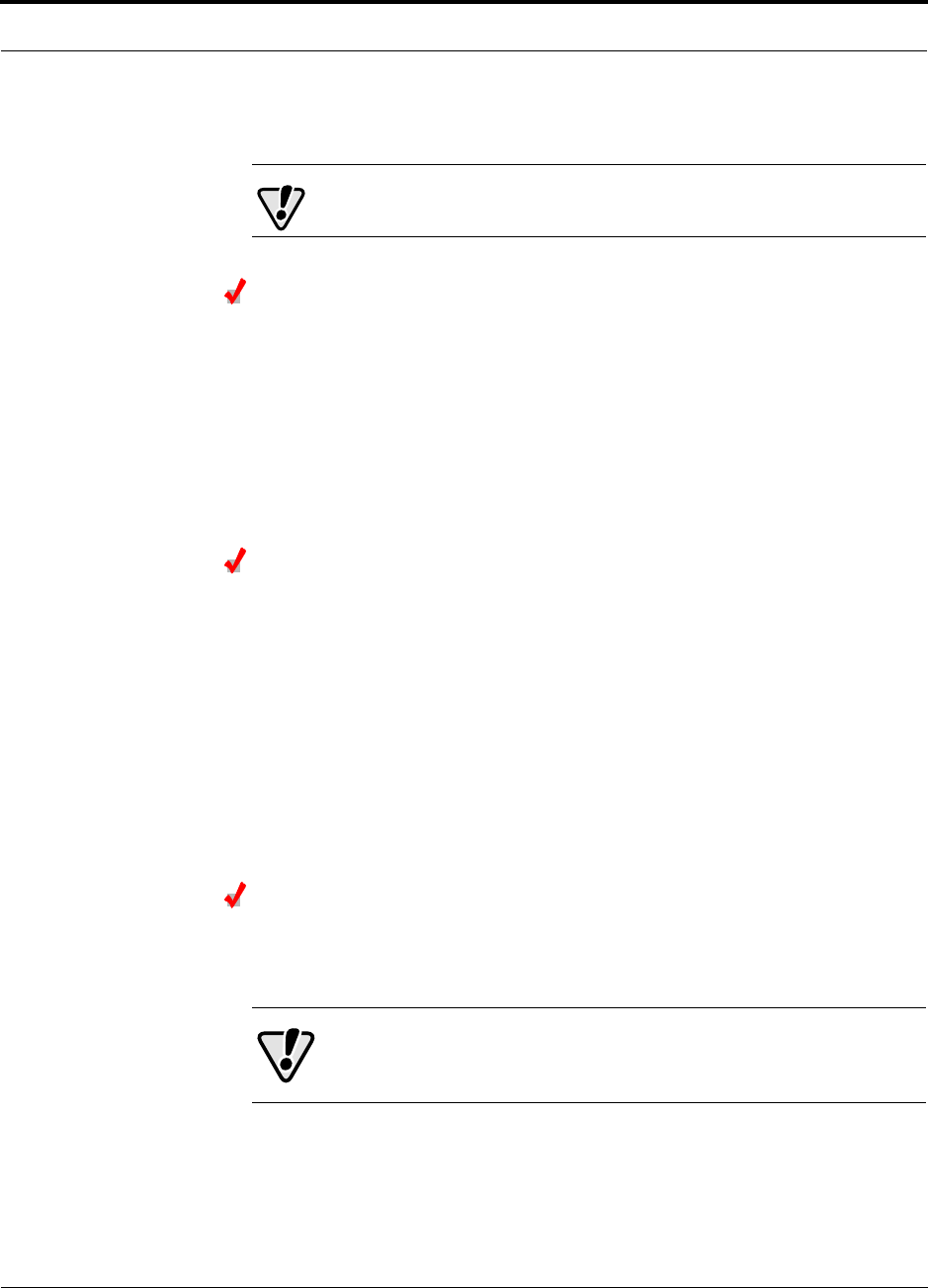
PN 8700-10 Help Hot Line (U.S. only): 1-800-530-9960 6-11
620003-0
PRELIMINARY Installing RAUs and Passive Antennas
6.4.1 Installing RAUs and Passive Antennas
CAUTION: Install RAUs in indoor locations only.
Installing RAUs
Mount all RAUs in the locations marked on the floor plans.
Considerations:
• Install iDEN and 800 MHz cellular RAUs so that their antennas will be at
least 6 to 8 meters (20 to 26 feet) apart.
• Keep at least 76 mm (3 in.) clearance around the RAU to ensure proper venting
• Always mount the RAU with the flat face against the mounting surface
Installing Passive Antennas
Refer to the manufacturer’s installation instructions to install passive antennas.
Passive antennas are usually installed below the ceiling. If they are installed above
the ceiling, the additional loss due to the ceiling material must be considered when
estimating the antenna coverage area.
Considerations:
• Use coaxial cable with the least amount of loss possible.
• Keep iDEN and 800 MHz cellular antennas at least 6 to 8 meters (20 to 26 ft)
apart.
Connecting the Antenna to the RAU
Connect a passive antenna to the SMA male connector on the RAU using coaxial
cable.
CAUTION:When connecting to the SMA female connector on
the RAU and passive antenna, DO NOT over-tighten the connec-
tor. Firmly hand-tightening the connector is adequate.

Installing Unison Components PRELIMINARY
6-12 InterReach Unison User Guide and Reference Manual PN 8700-10
620003-0
Testing and Connecting the ScTP Cable
Consideration:
• Before connecting the ScTP cable to the RAU, confirm that it meets TIA/EIA
568-A standard and the TIA/EIA/IS-729 supplement.
To test and connect the ScTP cable:
1. Perform cable testing.
Test results are required for the final As-Built Document.
Cable length:
– Absolute Minimum: 10 m (33 ft)
– Recommended Minimum: 25 m (82 ft)
– Recommended Maximum: 100 m (328 ft)
– Absolute Maximum: 150 m (492 ft)
2. Label the cable and make a note of the designation.
This information is needed when connecting the cable to the Expansion Hub.
3. Connect the cable to the RJ-45 female port on the RAU.
Power is supplied by the Expansion Hub. Because the Expansion Hub is not yet
connected, no LEDs will illuminate.
6.4.1.1 Installing RAUs in a Neutral Host System
When installing both iDEN and cellular systems in parallel, either as dual-band or
neutral host systems, special provision must be taken to assure that the individual
RAUs do not interfere with each other.
The 800 MHz cellular and iDEN RAU’s antennas must be separated by 6 to 8
meters (20 to 26 feet) to assure that the iDEN downlink signals do not interfere
with the cellular uplink signals.
PN 8700-10 Help Hot Line (U.S. only): 1-800-530-9960 6-13
620003-0
PRELIMINARY Installing Expansion Hubs
6.4.2 Installing Expansion Hubs
The Expansion Hub (2U high) can mount in a standard 19 in. (483 mm) equipment
rack or in a wall-mountable equipment rack that is available from LGC Wireless.
Allow clearance of 76 mm (3 in.) front and rear and 51 mm (2 in.) sides for air circu-
lation.
Install the Expansion Hub in a horizontal position only.
CAUTION: Install Expansion Hubs in indoor locations only.
Installing an Expansion Hub in a Rack
Consideration:
• The Expansion Hub is shipped with #10-32 mounting screws. Another common
rack thread is #12-24. Confirm that the mounting screws match the rack’s threads.
• If you want to move the mounting brackets to a mid-mounting position, see Install-
ing an Expansion Hub in a Wall-Mounted Rack on page 6-14.
To install the hub in a rack:
1. Insert spring nuts into the rack where needed or use existing threaded holes.
2. Place the Expansion Hub into the rack from the front.
3. Align the flange holes with the spring nuts installed in Step 1.
4. Insert the mounting screws in the appropriate positions in the rack.
5. Tighten the mounting screws.
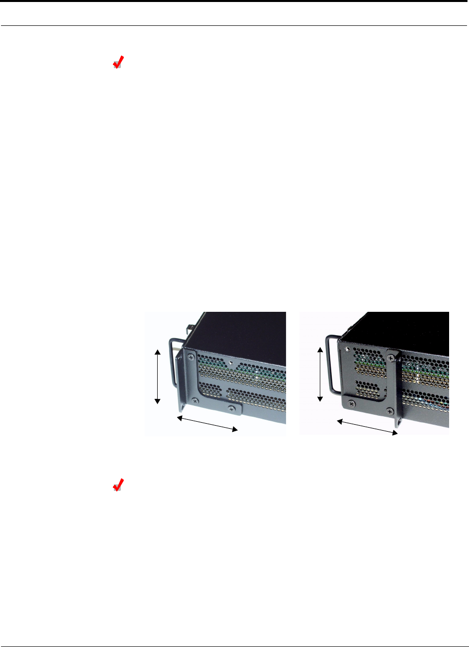
Installing Unison Components PRELIMINARY
6-14 InterReach Unison User Guide and Reference Manual PN 8700-10
620003-0
Installing an Expansion Hub in a Wall-Mounted Rack
Considerations:
• The rack and the Expansion Hub are both 305 mm (12 in.) deep. The rack mount-
ing brackets on the Expansion Hub must be moved from the front position to allow
for the 76 mm (3 in.) rear clearance required.
• The maximum weight the rack can hold is 22.5 kg (50 lbs).
To install the hub in a wall-mounted rack:
1. Attach the equipment rack to the wall using the screws that are provided.
The rack must be positioned so that the Expansion Hub will be in a horizontal
position when it is installed.
2. Remove both of the rack mounting brackets from the hub.
3. Reattach each of the rack mounting brackets to the opposite side of the hub from
which it came.
Refer to the following figure for bracket placement.
4. Attach the Expansion Hub to the rack.
Installing an Optional Cable Manager in the Rack
• Using the screws provided, fasten the cable manager to the rack, immediately
above or below the Expansion Hub.
Right Rack Mounting Bracket as
installed from the factory.
Left Rack Mounting Bracket installed on
the right side of the hub.
3''
3.5''
3''
3.5''

PN 8700-10 Help Hot Line (U.S. only): 1-800-530-9960 6-15
620003-0
PRELIMINARY Installing Expansion Hubs
Powering On the Expansion Hub
1. Connect the AC power cord to the Expansion Hub.
2. Plug the power cord into an AC power outlet.
3. Turn on the power to the Expansion Hub and check that all the LED lamps are
functioning properly.
Upon power-up, the LEDs will blink for five seconds for a visual check that they
are functioning. After the five-second test:
•The
POWER and UL STATUS LEDs should be green.
•The
E-HUB STATUS and DL STATUS LEDs should be red because the Main Hub
is not yet connected.
• All port LEDs should be off because no RAUs are connected yet.
NOTE: Leave the dust caps on the fiber ports until you are ready to connect the fiber
optic cables.
Testing and Connecting the Fiber Cables
Considerations:
• Before connecting the fiber cables, confirm that their optical loss does not exceed
3 dB optical budget.
• If fiber distribution panels are used, confirm that the total optical loss of fiber
cable, from the Main Hub through distribution panels and patch cords to the
Expansion Hub, does not exceed the optical budget.
• Make sure the fiber cable’s connectors are SC/APC (angle-polished).Using any
other connector type will result in degraded system performance and may damage
the equipment.
NOTE: Observe all Fiber Port Safety Precautions listed in Section 6.2.3 on page 6-4.
To test the fiber cables:
1. Perform cable testing and record the results.
Test results are required for the final As-Built Document.
2. Make a note of which cable you will use for uplink and downlink.
This information is needed when connecting the cables to the Main Hub.

Installing Unison Components PRELIMINARY
6-16 InterReach Unison User Guide and Reference Manual PN 8700-10
620003-0
To clean the fiber ports:
Use compressed air to blow dust out of each fiber port before you insert the SC/APC
connector. Note that compressed air should not leave any residue as this will contam-
inate the fiber port.
To clean the fiber connectors:
Be sure that the fiber cable’s SC/APC connectors are clean and free of dust or oils. If
the fiber connector front face is not free of dust or oils, follow the manufacturer’s rec-
ommendations for cleaning it.
To connect the fiber cables:
The fiber cable is labeled with either 1 or 2, or is color-coded. In addition to these
labels, you should add a code that identifies which port on the Main Hub is being
used and which Expansion Hub the cables are intended for. This differentiates the
connectors for proper connection between the Main Hub and Expansion Hubs.
If the fiber jumper is labeled with 1 or 2:
1. Connect 1 to UPLINK on Expansion Hub.
2. Connect 2 to DOWNLINK on Expansion Hub.
3. Label both ends of each cable with which Main Hub port is used.
For example:
First pair to Main Hub port 1: 11 (uplink), 12 (downlink);
Second pair to Main Hub port 2: 21 (uplink), 22 (downlink);
Third pair to Main Hub port 3: 31 (uplink), 32 (downlink); and so on.
4. Record which number you connected to UPLINK and DOWNLINK.
This information is needed when connecting the other end of the fiber cable to the
Main Hub’s fiber ports.
If the fiber jumper is color-coded (for example, “blue” or “red”):
1. Connect “blue” to UPLINK on Expansion Hub.
2. Connect “red” to DOWNLINK on Expansion Hub.
3. Label both ends of each cable with which Main Hub port is used.
For example:
First pair to Main Hub port 1: 11 (uplink), 12 (downlink);
Second pair to Main Hub port 2: 21 (uplink), 22 (downlink);
Third pair to Main Hub port 3: 31 (uplink), 32 (downlink); and so on.
4. Record which color and port number you connected to UPLINK and DOWNLINK.
This information is needed when connecting the other end of the fiber cable to the
Main Hub’s fiber ports.

PN 8700-10 Help Hot Line (U.S. only): 1-800-530-9960 6-17
620003-0
PRELIMINARY Installing Expansion Hubs
Connecting the ScTP Cables
Considerations:
• Confirm that the cables have been tested and the results recorded.
To connect the ScTP cables:
1. Connect the ScTP cables to any available RJ-45 port on the Expansion Hub.
2. Record which RAU you are connecting to which port.
This information is required for the As-Built Document.
3. Tie-off cables or use the optional cable manager to avoid damaging the connec-
tors because of cable strain.
Checking the RJ-45 Port LEDs
•The LINK LED should be green indicating that power is being supplied to the RAU.
•The
RAU LED should be red indicating that communication is established but a
band is not programmed.
•If the LINK LED is red and the RAU LED is off, then the RAUs are not commu-
nicating with the Expansion Hub.
• If the LEDs are off, the RAU is not drawing power.

Installing Unison Components PRELIMINARY
6-18 InterReach Unison User Guide and Reference Manual PN 8700-10
620003-0
6.4.2.1 Troubleshooting Expansion Hub LEDs During Installation
• All Expansion Hub LINK and E-HUB/RAU LEDs with RAUs connected should indi-
cate Green/Red, which indicates that the RAU is powered on and communication
has been established.
• The Expansion Hub UL STATUS LED should be Green.
6.4.2.2 Installing Expansion Hubs in a Neutral Host System
Installing Expansion Hubs in a neutral host system is the same as described in
Section 6.4.2 on page 6-13.
If rack-mounting the Expansion Hubs, we recommend mounting all neutral host sys-
tem hubs in the same rack(s) or location, grouped by frequency or carrier. For exam-
ple, group the Expansion Hubs for the iDEN carrier(s) together, then the 800 MHz
cellular carrier(s), and so on.
Table 6-5 Troubleshooting Expansion Hub LEDs During Installation
During
Installation LED State Action Impact
Expansion Hub
power is On and
no RAUs are
connected
POWER Off Check AC power; check that the
Expansion Hub power-on switch
is on; replace the Expansion Hub.
Expansion Hub is not powering on.
LINK LEDs
on but
didn’t
blink
through
all states
Replace the Expansion Hub. Microcontroller not resetting properly;
flash memory corrupted.
E-HUB/RAU
UL STATUS Red Replace the Expansion Hub. The Expansion Hub laser is not opera-
tional; no uplink between the Expansion
Hub and Main Hub.
LINK Red Port unusable; replace the Expan-
sion Hub when possible.
Current sensor fault; do not use the port.
E-HUB/RAU Off
Connect RAU LINK Off Check the Cat-5/6 cable. Power is not getting to the RAU.
E-HUB/RAU Off
LINK Red Test the Cat-5/6 cable. If the cable
tests OK, try another port. If the
second port’s LEDs are Red/Off,
replace the RAU. If the second
RAU doesn’t work; replace the
Expansion Hub.
Power levels to RAU are not correct;
communications are not established.
If the second port works, flag the first
port as unusable; replace EH when possi-
ble.
E-HUB/RAU Off
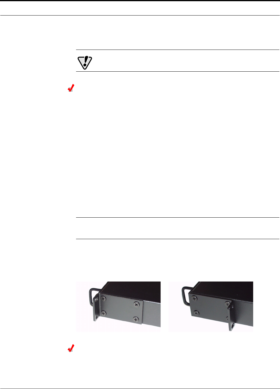
PN 8700-10 Help Hot Line (U.S. only): 1-800-530-9960 6-19
620003-0
PRELIMINARY Installing a Main Hub
6.4.3 Installing a Main Hub
CAUTION: Install Main Hubs in indoor locations only.
Installing a Main Hub in a Rack
The Main Hub (1U high) mounts in a standard 19 in. (483 mm) equipment rack.
Allow clearance of 76 mm (3 in.) front and rear, and 51 mm (2 in.) on both sides for
air circulation.
Consideration:
• The Main Hub is shipped with #10-32 mounting screws. Another common rack
thread is #12-24. Confirm that the mounting screws match the rack’s threads.
To install the hub in a rack:
1. Insert spring nuts into rack where needed or use existing threaded holes.
2. Place the Main Hub into the rack from the front.
3. Align the flange holes with the spring nuts installed in Step 1.
4. Insert the mounting screws in the appropriate positions in the rack.
5. Tighten the mounting screws.
NOTE: Do not turn on the Main Hub until you’ve started the AdminMan-
ager software (see Section 6.5 on page 6-21).
Rack-mounting Option
You can flip the rack mounting brackets, as shown in the following figure, so the hub
can be mounted 76 mm (3 in.) forward in the rack.
Installing an Optional Cable Manager in the Rack
• Using the screws provided, fasten the cable manager to the rack, immediately
above or below the Main Hub.

Installing Unison Components PRELIMINARY
6-20 InterReach Unison User Guide and Reference Manual PN 8700-10
620003-0
6.4.4 Installing Main Hubs in a Neutral Host System
Installing Main Hubs in a neutral host system is the same as described in
Section 6.4.3 on page 6-19.
We recommend mounting all neutral host system Main Hubs in the same rack(s),
grouped by frequency or carrier. For example, group the Main Hubs for the iDEN
carrier(s) together, then the 800 MHz cellular carrier(s), and so on.
Connecting to base stations and repeaters is the same as described in Section 6.6 on
page 6-26 and Section 6.6.1 on page 6-30.

PN 8700-10 Help Hot Line (U.S. only): 1-800-530-9960 6-21
620003-0
PRELIMINARY Starting and Configuring the System
6.5 Starting and Configuring the System
Connecting a Laptop and Starting the AdminManager Software
Considerations:
• The AdminManager software is installed on a laptop computer that meets the
requirements that are listed on page 7-2.
• Null modem cable with female connectors is needed.
To connect and start the AdminManager software:
1. Connect the null modem cable to the laptop and then to the RS-232 port on the
Main Hub’s front panel.
2. Turn on the laptop and start the AdminManager software.
The main Installation Wizard window is displayed when the software is ready.
Powering On the Main Hub
After mounting the Main Hub in the rack, connect it to the AC power. You may use
multiple outlet surge protectors for multiple Main Hubs.
1. Connect the AC power cord to the Main Hub.
2. Plug the power cord into an AC power outlet.
3. Turn on the power.
Upon power-up, the LEDs will blink for five seconds for a visual check that they
are functioning. After the five-second test:
•The
POWER LED should be green.
•The MAIN HUB STATUS LED should be red because a band has not been pro-
grammed.
• All fiber port LEDs should be off, indicating that no fiber cables are connected.
NOTE: Leave the dust caps on the fiber ports until you are ready to connect the fiber
optic cables.

Installing Unison Components PRELIMINARY
6-22 InterReach Unison User Guide and Reference Manual PN 8700-10
620003-0
Connecting the Fiber Cables to the Main Hub
Considerations:
• Before connecting the fiber cables, confirm that their optical loss does not exceed
3 dB optical budget.
• If fiber distribution panels are used, confirm that the total optical loss of fiber
cable, from the Main Hub through distribution panels and patch cords to the
Expansion Hub, does not exceed the optical budget.
• Make sure the fiber cable’s connectors are SC/APC (angle-polished). Using any
other connector type will result in degraded system performance and may damage
the equipment.
NOTE: Observe all Fiber Port Safety Precautions listed in Section 6.2.3 on page 6-4.
To clean the fiber ports:
Use compressed air to blow dust out of each fiber port before you insert the SC/APC
connector. Note that compressed air should not leave any residue as this will contam-
inate the fiber port.
To clean the fiber connectors:
Be sure that the fiber cable’s SC/APC connectors are clean and free of dust or oils. If
the fiber connector front face is not free of dust or oils, follow the manufacturer’s rec-
ommendations for cleaning it.
To connect the fiber cables:
The fiber cable is labeled with either 1 or 2, or is color-coded. For proper connection
between the Main Hub ports and the Expansion Hub ports, refer to the numbering or
color-coded connections you recorded when installing the Expansion Hub(s).
If the fiber jumper is labeled with 1 or 2:
1. Connect 1s to UPLINK ports on the Main Hub.
Refer to the connections you recorded, or the cable label, when the Expansion
Hub(s) were installed to know which Main Hub UPLINK port to use.
2. Connect 2s to DOWNLINK ports on the Main Hub.
Refer to the connections you recorded, or the cable label, when the Expansion
Hub(s) were installed to know which Main Hub DOWNLINK port to use.
If the fiber jumper is color-coded (for example, “blue” or “red”):
1. Connect “blue”s to UPLINK ports on the Main Hub.
Refer to the connections you recorded, or the cable label, when the Expansion
Hub(s) were installed to know which Main Hub UPLINK port to use.
2. Connect “red”s to DOWNLINK ports on the Main Hub.
Refer to the connections you recorded, or the cable label, when the Expansion
Hub(s) were installed to know which Main Hub DOWNLINK port to use.

PN 8700-10 Help Hot Line (U.S. only): 1-800-530-9960 6-23
620003-0
PRELIMINARY Starting and Configuring the System
Checking the Main Hub’s Fiber Port LEDs
•The LINK LED should be green if the fiber is connected to the Expansion Hub, and
communication and optical power are okay.
•The
E-HUB/RAU LED should be red because a band has not been programmed.
•If the LINK LED is red and the E-HUB/RAU LED is off, there is no communica-
tion with the Expansion Hub. Check the fiber cables (downlink first); a cable
may be broken or the optical link budget may be exceeded.
•If the PORT LEDs are blank (off), the Main Hub does not recognize the pres-
ence of an Expansion Hub. Check the fiber cables (uplink first); a cable may be
broken or the optical link budget may be exceeded. Check to ensure that the
cables are connected at the Expansion Hub, and that the Expansion Hub’s
power is on.
NOTE: Refer to Section 10 for troubleshooting.

Installing Unison Components PRELIMINARY
6-24 InterReach Unison User Guide and Reference Manual PN 8700-10
620003-0
6.5.1 Troubleshooting Main Hub LEDs During Installation
The following Main Hub LED indications assume that the Expansion Hub LEDs have
already been checked.
• All Main Hub fiber port LEDs that have Expansion Hubs connected to them
should be Green/Red, indicating that the Expansion Hub is powered on and com-
munication has been established.
Table 6-6 Troubleshooting Main Hub LEDs During Installation Power On
During
Installation
Power On LED State Action Impact
Main Hub
power is On
with no
Expansion
Hubs con-
nected.
POWER Off Check AC power; check that the
Main Hub power-on switch is on;
replace Main Hub
Main Hub is not powering on.
LINK LEDs on
but didn’t
blink
through all
states
Replace the Main Hub. Microcontroller not resetting properly;
flash memory corrupted.
E-HUB/RAU
LINK Red The port is unusable; replace the
Main Hub when possible.
Fiber sensor fault, do not use the port.
E-HUB/RAU Off
Connect
Expansion
Hub Fiber
Pair
LINK Off Swap the uplink and downlink
cables. If the port LEDs do not illu-
minate, check the fiber uplink for
excessive optical loss.
Connect the fiber pair to another port.
If the second port’s LEDs do not illu-
minate Green/Red, replace the Main
Hub.
The Main Hub does not sense the
presence of the Expansion Hub.
If the second port works, flag the first
port as unusable; replace the Main
Hub when possible.
E-HUB/RAU Off
LINK Red If the Expansion Hub DL STATUS
LED is red, check the downlink fiber
cable for excessive optical loss.
Connect the fiber pair to another port.
If the second port’s LEDs do not illu-
minate Green/Red, replace the Main
Hub.
The Expansion Hub does not sense the
presence of the Main Hub.
If the second port works, flag the first
port as unusable; replace the Main
Hub when possible.
E-HUB/RAU Off

PN 8700-10 Help Hot Line (U.S. only): 1-800-530-9960 6-25
620003-0
PRELIMINARY Troubleshooting Main Hub LEDs During Installation
Configuring the Unison System
The system will not work until a band has been set and a system test is performed.
• The AdminManager software must be running on a PC/laptop that is connected to
the Main Hub’s front panel RS-232 connector.
1. Select the Installation Wizard (Local) mode radio button and click RUN.
The Step 1, Verify Hardware window is displayed.
Refer to Section 7.2 on page 7-12 for a description of the Installation wizard.
2. Confirm that all system devices are displayed in the System Status box and click
NEXT.
The Step 2, Set Operation Band window is displayed.
3. Select the desired frequency band and click APPLY.
4. Click NEXT if the message displayed indicates a successful band setting.
The Step 3, Configure System Parameters window is displayed.
5. Enter the desired parameters and click APPLY.
6. Click NEXT if the message displayed indicates a successful parameter setting.
The Step 4, Final System Test window is displayed.
7. Click APPLY to initiate the final system test.
During testing the system is off-line and a center band tone is being transmitted.
8. Click NEXT if the message displayed indicates a successful test.
The Finish window is displayed.
9. Click FINISH.
The AdminManager session is ended and the window is closed.
NOTE: Refer to Section 10 for troubleshooting.
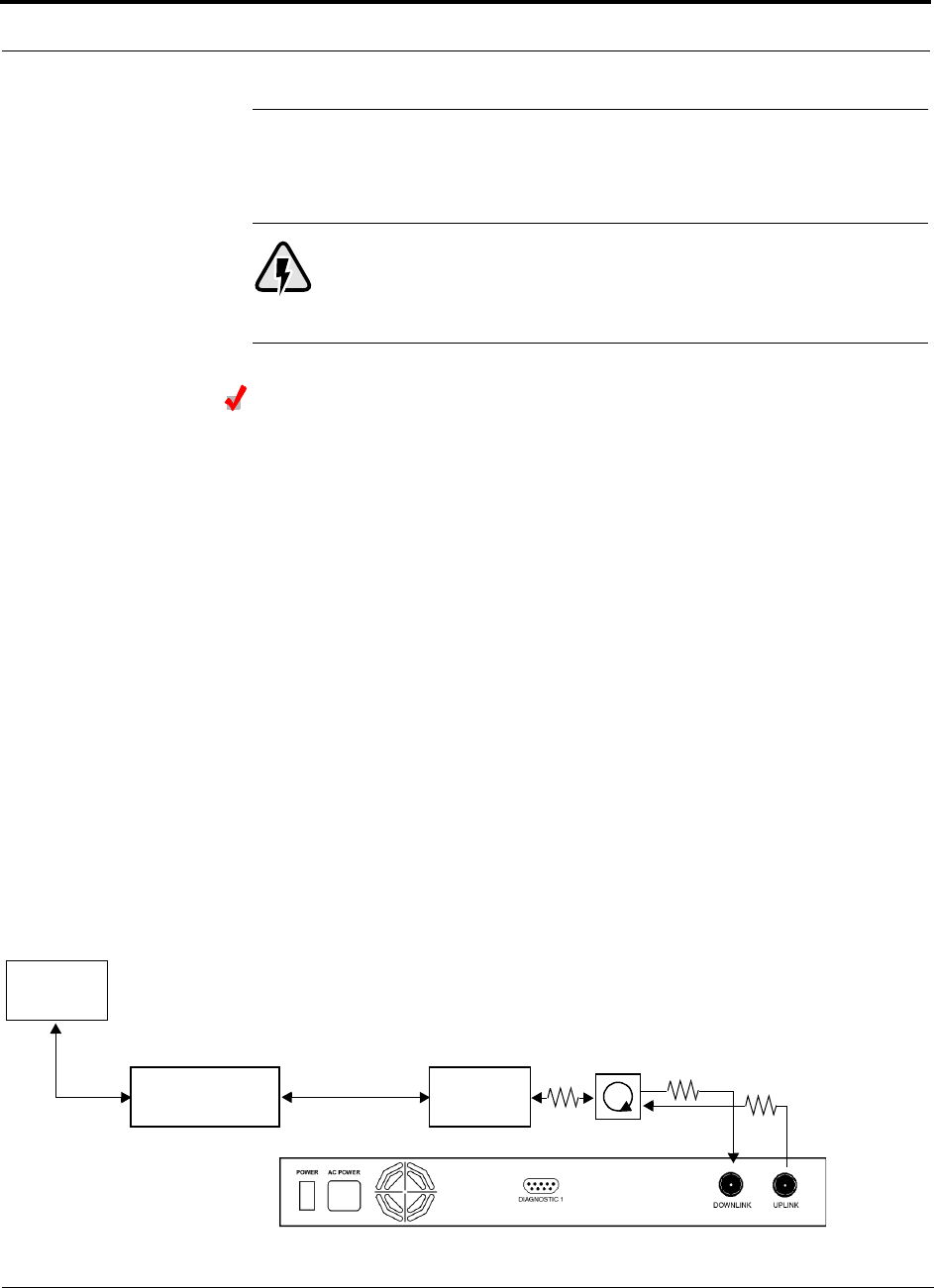
Installing Unison Components PRELIMINARY
6-26 InterReach Unison User Guide and Reference Manual PN 8700-10
620003-0
6.6 Interfacing a Main Hub to a Base Station or
Roof-top Antenna
WARNING: Exceeding the maximum input power could cause failure
of the Main Hub (refer to Section 8.1 on page 8-3 for maximum power
specifications). If the maximum composite power is too high, attenua-
tion is required.
Connecting a Main Hub to a Roof-top Antenna
It is recommended that you use a lightning arrestor or surge protector in a roof-top
antenna configuration. Insert the lightning arrestor or surge protector between the
roof-top antenna and the repeater that is connected to the Main Hub.
1. Connect an N-male to N-male coaxial cable to the roof-top antenna.
2. Connect the other end of the N-male to N-male coaxial cable to the grounded
surge suppressor.
3. Connect an N-male to N-male coaxial cable to the grounded surge suppressor.
4. Connect the other end of the N-male to N-male coaxial cable to the repeater.
5. Connect an N-male to N-male coaxial cable to the repeater.
6. Connect the other end of the N-male to N-male coaxial cable to the circulator
1connector.
7. Connect an N-male to N-male coaxial cable to the circulator 2connector.
8. Connect the other end of the N-male to N-male coaxial cable to the DOWNLINK
connector on the Main Hub.
Attenuation may be required to achieve the desired RF output at the RAU.
9. Connect an N-male to N-male coaxial cable to the circulator 3connector.
10. Connect the other end of the N-male to N-male coaxial cable to the UPLINK con-
nector on the Main Hub.
Roof-top
Antenna
Grounded
Surge Suppressor Repeater
N-male to N-male
Coaxial Cables
N-male to N-male
Coaxial Cable
N-male to N-male
Coaxial Cable Circulator Attenuator (optional)
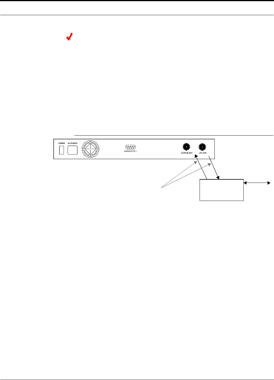
PN 8700-10 Help Hot Line (U.S. only): 1-800-530-9960 6-27
620003-0
PRELIMINARY Interfacing a Main Hub to a Base Station or Roof-top Antenna
Connecting a Main Hub to an In-Building Base Station
Connecting a Simplex Base Station to a Main Hub:
1. Connect an N-male to N-male coaxial cable to the transmit simplex connector on
the base station.
2. Connect the other end of the N-male to N-male coaxial cable to the DOWNLINK
connector on the Main Hub.
3. Connect an N-male to N-male coaxial cable to the receive simplex connector on
the base station.
4. Connect the other end of the N-male to N-male coaxial cable to the UPLINK con-
nector on the Main Hub.
Figure 6-1 Simplex Base Station to a Main Hub
N-male to N-male
Coaxial Cable
Base Station
Simplex T1/E1 to
Mobile
Switching
Center
Insert attenuator, if needed
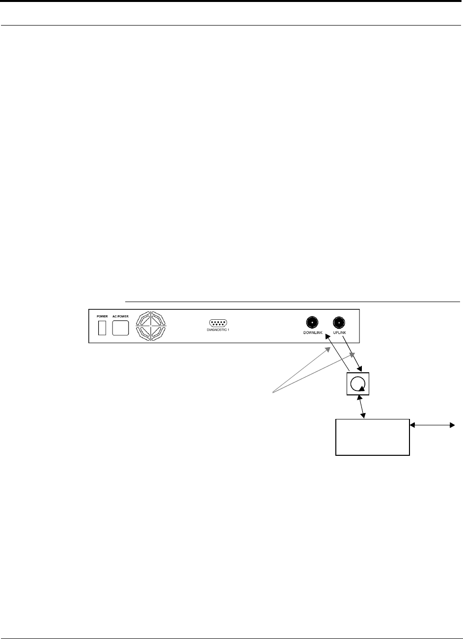
Installing Unison Components PRELIMINARY
6-28 InterReach Unison User Guide and Reference Manual PN 8700-10
620003-0
Connecting a Duplex Base Station to a Main Hub:
When connecting to a duplex base station, use a circulator between it and the Main
Hub.
You can insert attenuators between the circulator and Main Hub as needed; refer to
Section 8.6.1 on page 8-48 for more information.
1. Connect an N-male to N-male coaxial cable to the duplex connector on the base
station.
2. Connect the other N-male connector to a circulator.
3. Connect an N-male to N-male coaxial cable to the DOWNLINK connector on the
Main Hub.
4. Connect the other end of the N-male coaxial cable to the transmit connector on the
circulator.
5. Connect an N-male to N-male coaxial cable to the UPLINK connector on the Main
Hub.
6. Connect the other end of the N-male coaxial cable to the receive connector on the
circulator.
Figure 6-2 Duplex Base Station to a Main Hub
N-male to N-male
Coaxial Cable
Base Station
Duplex T1/E1 to
Mobile
Switching
Center
Insert attenuator, if needed N-male to N-male
Coaxial Cable
Circulator

PN 8700-10 Help Hot Line (U.S. only): 1-800-530-9960 6-29
620003-0
PRELIMINARY Interfacing a Main Hub to a Base Station or Roof-top Antenna
Connecting a Main Hub to Multiple Base Stations
You can use power combiner/splitters to connect a Main Hub to multiple base sta-
tions, as shown in the following figure.
Figure 6-3 Connecting a Main Hub to Multiple Base Stations
N-male to N-male
Coaxial Jumper Cables
N-male to N-male
Coaxial Jumper Cable
to Repeater or
Base Station
between Combiner/Splitter and
N-male to N-male
Coaxial Jumper Cables
between Combiner/Splitter and
Main Hub’s Uplink Port Main Hub’s Downlink Port
2 x 1 Power
Combiner/Splitter 2 x 1 Power
Combiner/Splitter
BTS 1
UL DL
BTS 2
UL DL
Insert attenuators, if needed
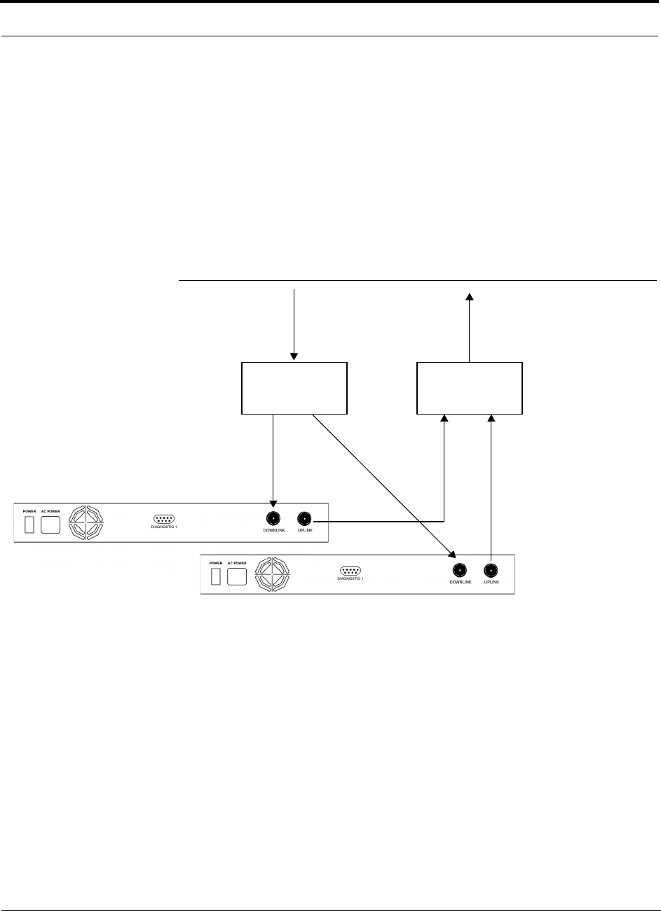
Installing Unison Components PRELIMINARY
6-30 InterReach Unison User Guide and Reference Manual PN 8700-10
620003-0
6.6.1 Connecting Multiple Main Hubs
You can use power combiner/splitters as splitters to connect multiple Main Hubs in
order to increase the total number of RAUs in a system. You can also use power com-
biner/splitters to combine base station channels in order to increase the number of RF
carriers the system transports.
The following figure shows connecting two Main Hubs to a simplex repeater or base
station. Connecting two Main Hubs increases the total number of supportable RAUs
from 32 to 64. Two Main Hubs support up to 8 Expansion Hubs which in turn support
up to 64 RAUs.
Figure 6-4 Connecting Two Main Hubs to a Simplex Repeater or Base Station
N-male to N-male
Coaxial Jumper Cables
N-male to N-male
Coaxial Jumper Cable
to Repeater or
Base Station
2 x 1 Power
Combiner/Splitter
N-male to N-male
Coaxial Jumper Cable
to Repeater or
Base Station
between Combiner/Splitter and N-male to N-male
Coaxial Jumper Cables
between Combiner/Splitter and
Main Hub’s Downlink Port
Main Hub’s Uplink Port
2 x 1 Power
Combiner/Splitter
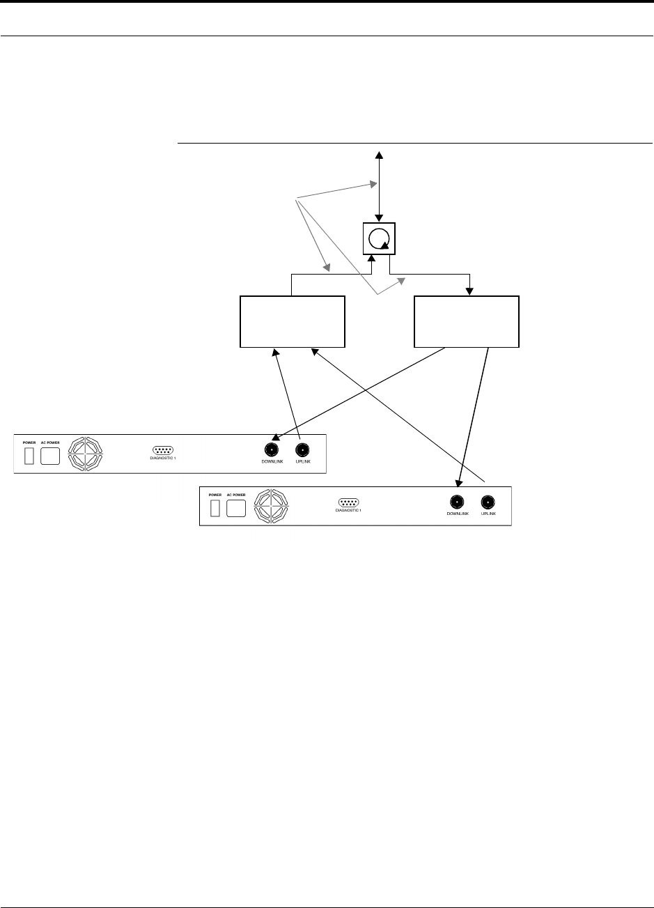
PN 8700-10 Help Hot Line (U.S. only): 1-800-530-9960 6-31
620003-0
PRELIMINARY Connecting Multiple Main Hubs
To connect two Main Hubs to a duplex repeater or base station, you need to use one
circulator and one more coaxial jumper cable, as shown in the following figure.
Figure 6-5 Connecting Two Main Hubs to a Duplex Repeater or Base Station
2 x 1 Power
Combiner/Splitter
N-male to N-male
Coaxial Jumper Cable
N-male to N-male
Coaxial Jumper Cables
2 x 1 Power
Combiner/Splitter
N-male to N-male
Coaxial Jumper Cable
Circulator
N-male to N-male
Coaxial Jumper Cable
to Repeater or
Base Station
between Combiner/Splitter and N-male to N-male
Coaxial Jumper Cables
between Combiner/Splitter and
Main Hub’s Downlink Port
Main Hub’s Uplink Port
Insert attenuator, if needed

Installing Unison Components PRELIMINARY
6-32 InterReach Unison User Guide and Reference Manual PN 8700-10
620003-0
Connecting Multiple Main Hubs to a Simplex Repeater
or Base Station
You will need the following:
• 2 hybrid power combiner/splitters; one for uplink and one for downlink (2x1 for
two Main Hubs, 3x1 for three, 4x1 for four, etc.)
• 1 N-male to N-male coaxial jumper cable between each power combiner/splitter
and the base station
• 2 N-male to N-male coaxial jumper cables between each power combiner/splitter
and each Main Hub
Figure 6-4 on page 6-30 illustrates this procedure.
1. Connect the power combiner/splitters to the repeater or base station using N-male
to N-male coaxial jumper cables:
a. From the first power combiner/splitter to the repeater or base station
b. From the second power combiner/splitter to the repeater or base station
2. Connect the power combiner/splitters to the Main Hubs:
a. From the first Main Hub’s UPLINK port to the first power combiner/splitter
b. From the first Main Hub’s DOWNLINK port to the second power com-
biner/splitter
c. From the second Main Hub’s UPLINK port to the first power combiner/splitter
d. From the second Main Hub’s DOWNLINK port to the second power com-
biner/splitter
3. Check Main Hub LEDs.
After connecting and powering on the Main Hub, check all LEDs to ensure that
the system is operating properly.
NOTE: Use a 50 ohm terminator on any unused power combiner/splitter ports.

PN 8700-10 Help Hot Line (U.S. only): 1-800-530-9960 6-33
620003-0
PRELIMINARY Connecting Multiple Main Hubs
Connecting Multiple Main Hubs to a Duplex Repeater
or Base Station
You will need the following:
• 2 hybrid power combiner/splitters; one for uplink and one for downlink (2x1 for
two Main Hubs, 3x1 for three, 4x1 for four, etc.)
• 2 N-male to N-male coaxial jumper cables to connect each Main Hub to the power
combiner/splitters
• 1 circulator
• 1 N-male to N-male coaxial jumper cable between each circulator and the repeater
or base station
• 1 N-male to N-male coaxial jumper cable1 between each circulator and power
combiner/splitter
Figure 6-5 on page 6-31 illustrates this procedure.
1. Connect the Circulator to the power combiner/splitters and to the repeater or base
station using one N-male to N-male coaxial jumper cable.
2. Connect each power combiner/splitter to the circulator using one N-male to
N-male coaxial jumper cable.
3. Connect the power combiner/splitter to the Main Hubs:
a. From the first Main Hub’s UPLINK port to the first power combiner/splitter
b. From the first Main Hub’s DOWNLINK port to the second power com-
biner/splitter
c. From the second Main Hub’s UPLINK port to the first power combiner/splitter
d. From the second Main Hub’s DOWNLINK port to the second power com-
biner/splitter
4. Check Main Hub LEDs.
After connecting and powering on the Main Hub, check all LEDs to ensure that
the system is operating properly.
NOTE: Use a 50 ohm terminator on any unused power combiner/splitter ports.

Installing Unison Components PRELIMINARY
6-34 InterReach Unison User Guide and Reference Manual PN 8700-10
620003-0
6.7 Connecting Contact Alarms to a Unison System
John Boyd: NO and NC contact sense info
Alarm Source intro
Alarm Sense intro
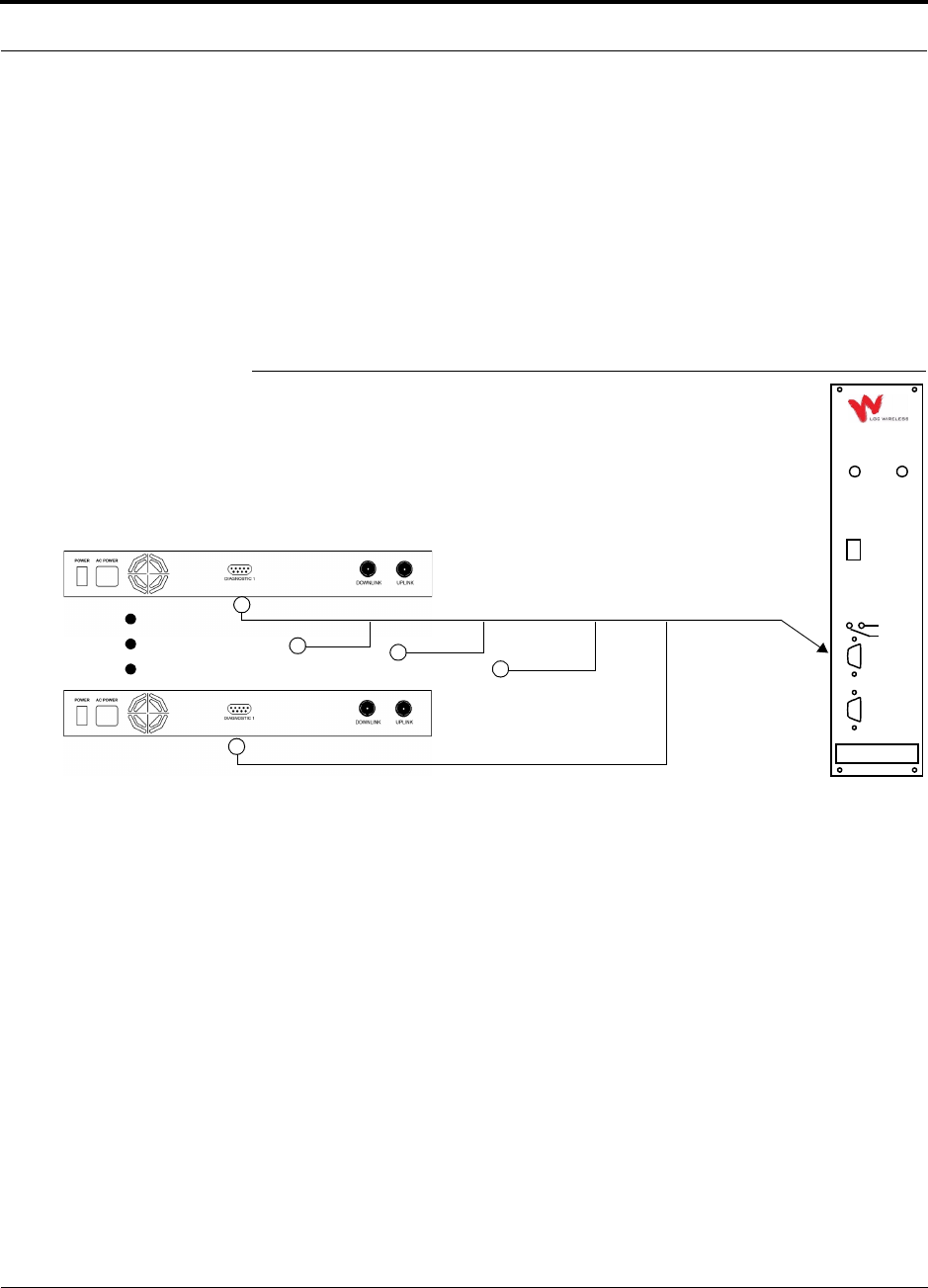
PN 8700-10 Help Hot Line (U.S. only): 1-800-530-9960 6-35
620003-0
PRELIMINARY Alarm Source
6.7.1 Alarm Source
Unison is always an alarm source, no matter what type of equiment you are connect-
ing to.
Using MetroReach Focus to Monitor Unison
When you connect MetroReach Focus to Unison, the Unison Main Hub is the output
of the alarms (alarm source) and Focus is the input (alarm sense), as shown in the fol-
lowing figure.
Figure 6-6 Connecting MetroReach to Unison
Unison Main Hub
RF OUT
DOWNLINK RF IN
UPLINK
FIBER
UPLINK
DOWNLINK
ALARM
RS-232C
MetroReach
Focus
RFM
5-Port Cable: 300117-0
Alarm
Sense
Alarm
Source
Alarm
Source
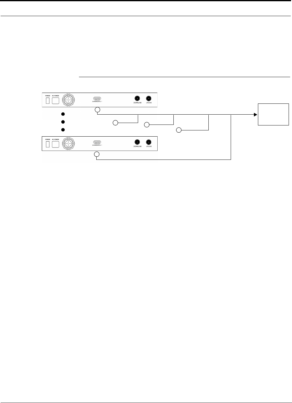
Installing Unison Components PRELIMINARY
6-36 InterReach Unison User Guide and Reference Manual PN 8700-10
620003-0
Using a Base Station to Monitor Unison
When you connect a BTS to Unison, the Unison Main Hub is the output of the alarms
(alarm source) and the BTS is the input (alarm sense), as shown in the following figure.
Figure 6-7 Connecting a BTS to Unison
Unison Main Hub
5-Port Cable: 300117-0
Alarm
Sense
Alarm
Source
Alarm
Source
BTS
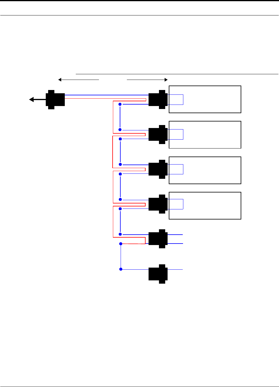
PN 8700-10 Help Hot Line (U.S. only): 1-800-530-9960 6-37
620003-0
PRELIMINARY Alarm Source
Daisy-Chained Alarm Source Cable
The daisy-chained alarm cable (PN 300117-0) that is used in these configurations is
shown in Figure 6-8.
Figure 6-8 Daisy-Chained Alarm Source Cable
1 meter (3 feet)
Pins 7 and 9
J2
LGCell, MetroReach Focus,
or Unison Alarm
DB-9 female Port
Pin 7
Pin 9 X
J3
Pin 7
Pin 9 X
J4
Pin 7
Pin 9 X
J5
Pin 7
Pin 9 X
J6J7
DB-9 male
Pins 7 and 9
DB-9 male
Pins 7 and 9
DB-9 male
Pins 7 and 9
DB-9 male
Pins 7 and 9
DB-9 male
Pin 7
DB-9 female
J1
DB-9 male 7
9
Pin 7
Pin 7
Option 1: Connect 5 units to cable using
J2 through J6; J7 is unused.
OR
Option 2: Connect four units to first cable
using J2 through J5, connect J6 to an
additional 300117-0 cable’s J1 connector;
J7 is unused.
OR
Option 3: Connect less than four units to
cable and terminate the circuit by con-
necting the J7 connector into the lowest
numbered unused male connector.
Pin 9
LGCell, MetroReach Focus,
or Unison Alarm
DB-9 female Port
LGCell, MetroReach Focus,
or Unison Alarm
DB-9 female Port
LGCell, MetroReach Focus,
or Unison Alarm
DB-9 female Port
to Unison,
Base Station,
or MetroReach
Focus
(use male-to-male
adapter, included with
cable, when connecting
to Unison or MetroReach)
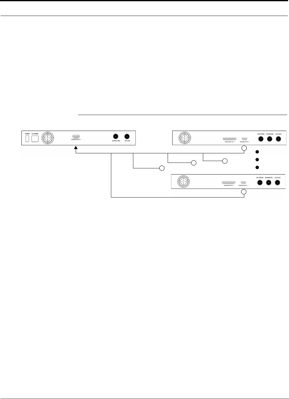
Installing Unison Components PRELIMINARY
6-38 InterReach Unison User Guide and Reference Manual PN 8700-10
620003-0
6.7.2 Alarm Sense
Use the AdminManager to enable the Unison system for “alarm sense” when con-
necting to the contact closure of LGCell Main Hubs.
Using Unison to Monitor LGCells
When you connect LGCell to Unison, the Unison Main Hub is the input of the alarms
(alarm sense) and the LGCell is the output (alarm source), as shown in the following
figure.
Figure 6-9 Connecting LGCell to Unison
Up to 5 LGCell Main HubsUnison Main Hub
5-Port Cable: 300117-0
Alarm
Sense Alarm
Source
Alarm
Source
John: How do I show the adaptor in this drawing?


Installing Unison Components PRELIMINARY
6-40 InterReach Unison User Guide and Reference Manual PN 8700-10
620003-0
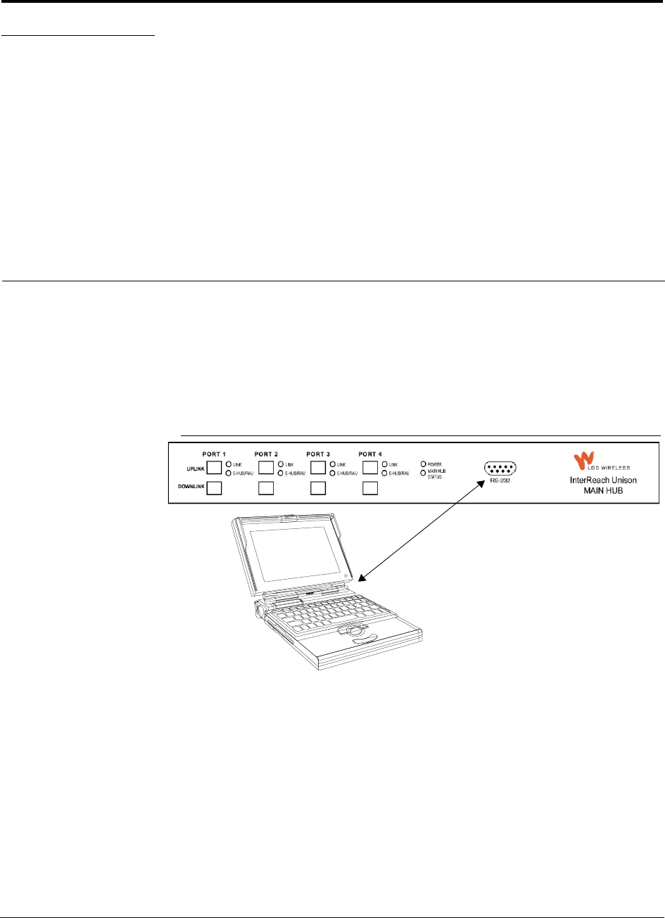
PN 8700-10 InterReach Unison User Guide and Reference Manual 7-1
620003-0
PRELIMINARY
SECTION 7 Installing and Using the
AdminManager Software
The AdminManager software is used to install, configure, and maintain the Unison
system from a PC or laptop that you connect directly to a Main Hub’s front panel
serial port.
You can use the AdminManager to remotely view system status by connecting a PC
or laptop to the Unison system via a dialup modem.
Figure 7-1 PC Connected to Main Hub

Installing and Using the AdminManager Software PRELIMINARY
7-2 InterReach Unison User Guide and Reference Manual PN 8700-10
620003-0
7.1 Installing the AdminManager Software
7.1.1 PC/Laptop Requirements
• Operating System:
• Windows 2000 Professional (recommended)
• Windows 98 SE with IE 5.0
• 1 Communication Port (COM1–COM4)
• 133 MHz or higher Pentium-compatible CPU
• 64 MB memory (Windows 2000) or 32 MB (Windows 98 SE)
• At least 150 MB free disk space
• VGA or higher resolution
• Standard 9600 Modem
•CD-ROM drive
• DB-9 female-to-DB-9 female NULL modem cable
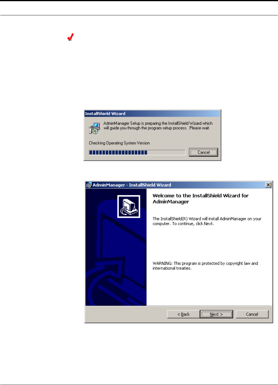
PN 8700-10 Help Hot Line (U.S. only): 1-800-530-9960 7-3
620003-0
PRELIMINARY PC/Laptop Requirements
Installing AdminManager
Install the AdminManager software on a PC/laptop that meets the requirements as
described in Section 7.1.1.
1. Turn on the PC/laptop and insert the AdminManager CD into the PC/laptop’s CD
drive.
setup.exe is automatically launched.
The following pop-up window is displayed while InstallShield checks the PC’s
system.
The Welcome to InstallShield Wizard window is displayed.
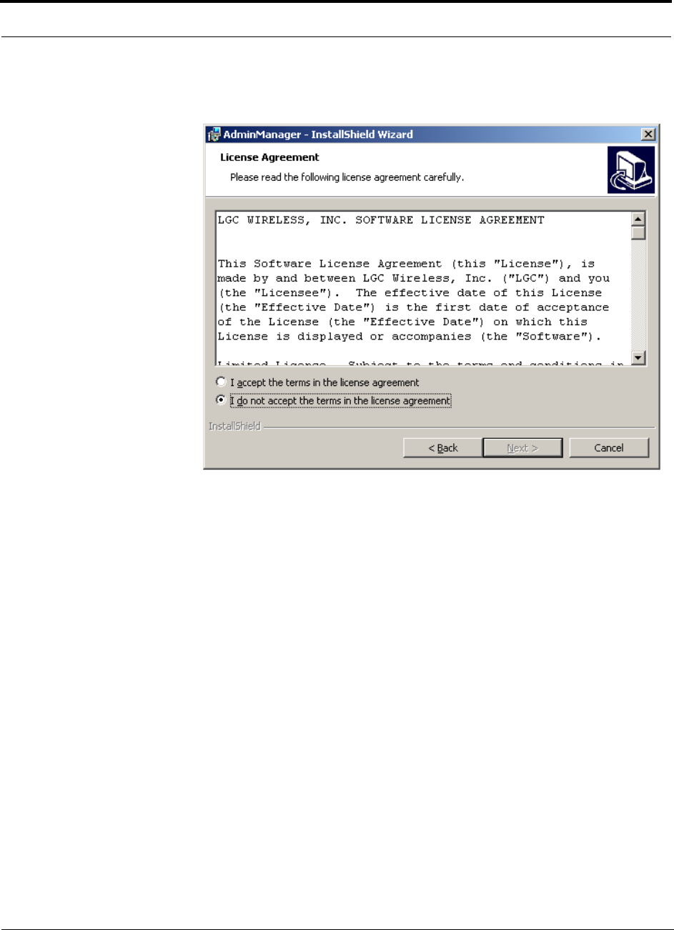
Installing and Using the AdminManager Software PRELIMINARY
7-4 InterReach Unison User Guide and Reference Manual PN 8700-10
620003-0
2. Click the NEXT button to begin the AdminManager installation.
The License Agreement window is displayed.
If you select the “I do not accept” radio button, the InstallShield Wizard stops and
the windows close.
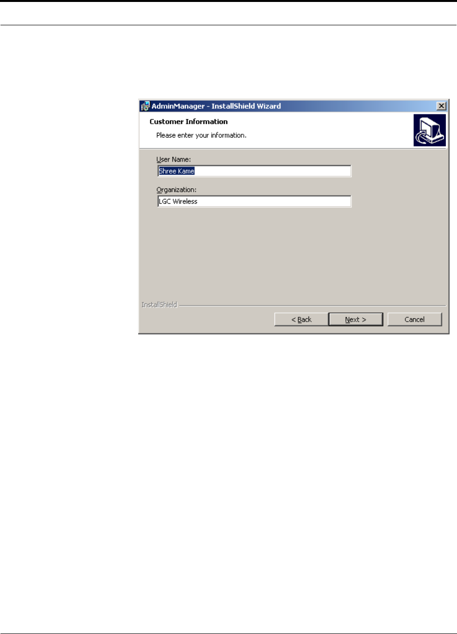
PN 8700-10 Help Hot Line (U.S. only): 1-800-530-9960 7-5
620003-0
PRELIMINARY PC/Laptop Requirements
3. Read the agreement and select the “I accept” radio button, and then click the NEXT
button.
The Customer Information window is displayed.
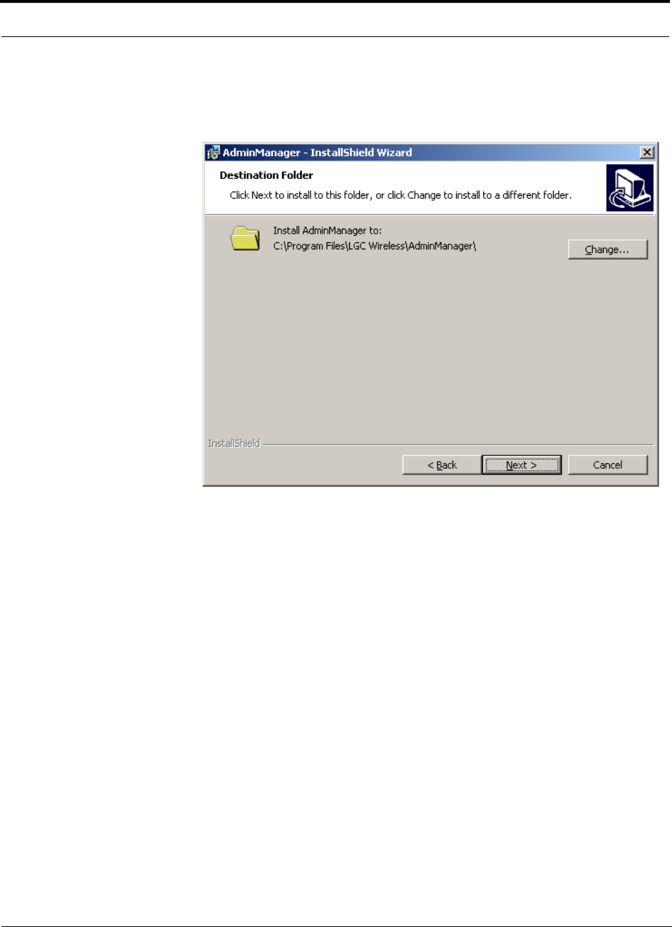
Installing and Using the AdminManager Software PRELIMINARY
7-6 InterReach Unison User Guide and Reference Manual PN 8700-10
620003-0
4. Enter a User Name and Organization in the text boxes, and then click the NEXT
button.
The Destination Folder window is displayed
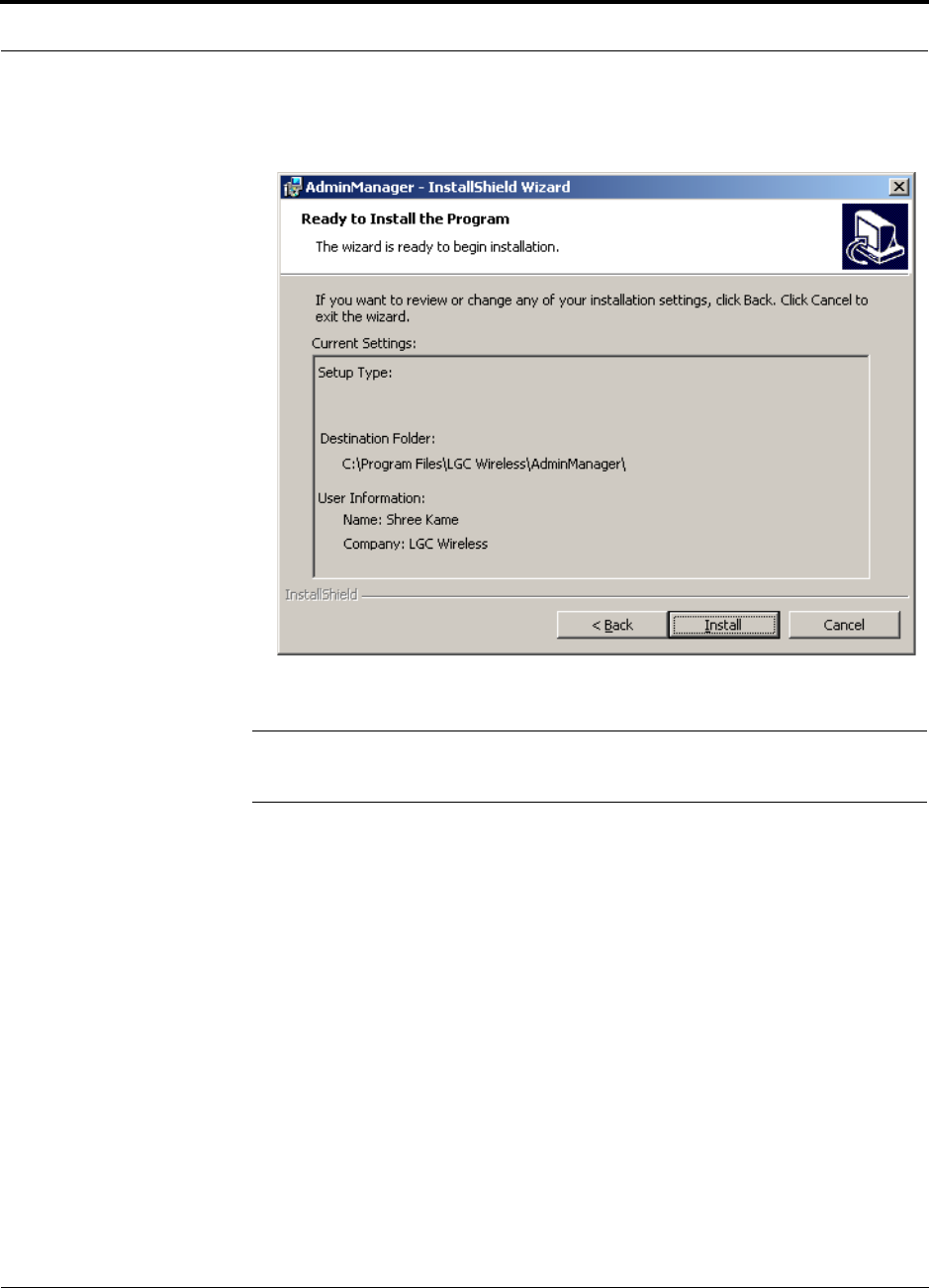
PN 8700-10 Help Hot Line (U.S. only): 1-800-530-9960 7-7
620003-0
PRELIMINARY PC/Laptop Requirements
5. Click the NEXT button to accept the default destination.
The Ready to Install the Program window is displayed.
NOTE: To change information that is displayed in the Ready to Install the Program
window, click the BACK button and make changes in previous windows.
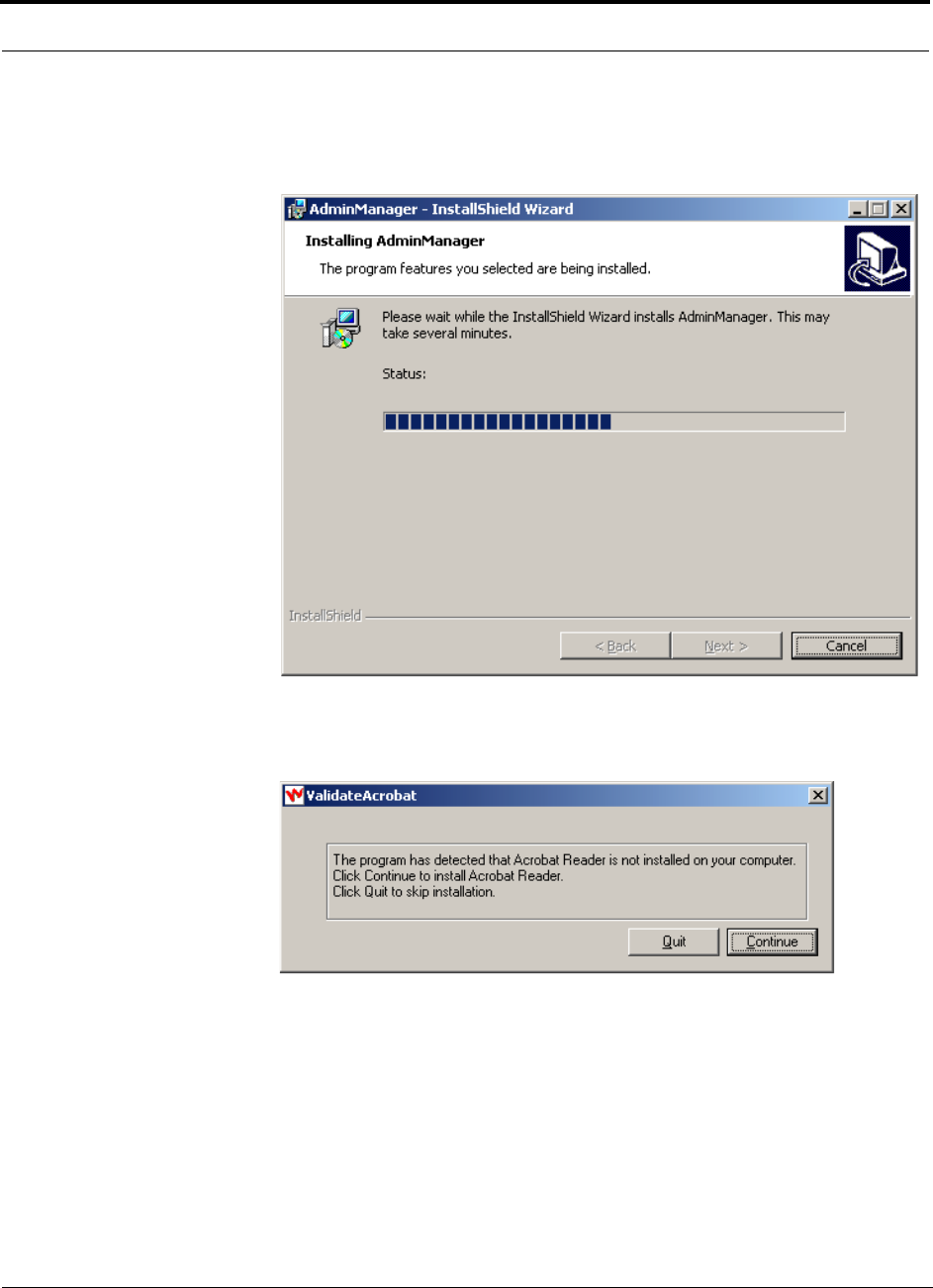
Installing and Using the AdminManager Software PRELIMINARY
7-8 InterReach Unison User Guide and Reference Manual PN 8700-10
620003-0
6. Click the INSTALL button if the information that is displayed in the Ready to Install
the Program window is correct.
The Installing AdminManager window is displayed.
PDF files are used for Help. If the InstallShield Wizard detects that the PC does
not have software for viewing PDF files, the following pop-up is displayed.
• Click CONTINUE to install Acrobat Reader from the CD onto your PC.
• Click QUIT to skip the installation of Acrobat Reader.
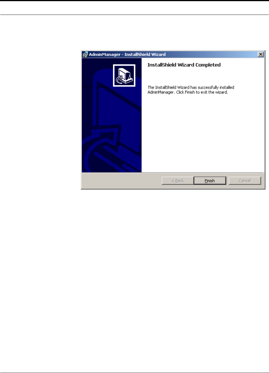
PN 8700-10 Help Hot Line (U.S. only): 1-800-530-9960 7-9
620003-0
PRELIMINARY PC/Laptop Requirements
When the installation is finished, the InstallShield Wizard Completed window is
displayed.
7. Click the FINISH button to end the InstallShield Wizard session and close the win-
dow.
An AdminManager shortcut is added to your PC’s Start menu and an icon is
added to your desktop.
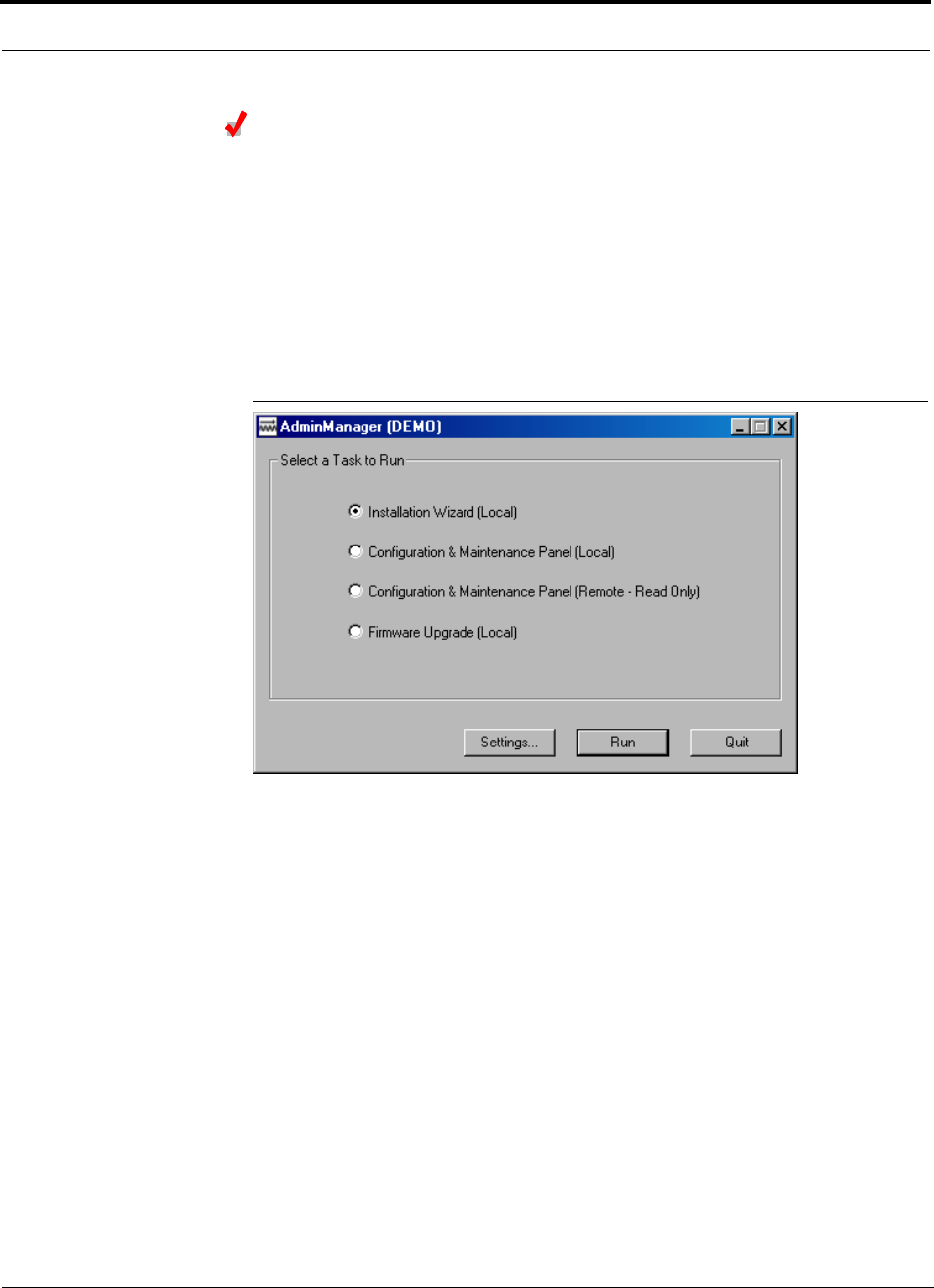
Installing and Using the AdminManager Software PRELIMINARY
7-10 InterReach Unison User Guide and Reference Manual PN 8700-10
620003-0
Starting AdminManager
1. Using the NULL modem cable, connect the PC/laptop to the Main Hub’s front
panel RS-232 connector.
2. Turn on the power to the Main Hub, if it is not already on.
3. Double-click the AdminManager icon to start the software.
Alternately, you can click the Start button that is on the PC’s taskbar, click Pro-
grams, click AdminManager, and then click the AdminManager application.
The following window is displayed when AdminManager starts.
Figure 7-2 AdminManager Start Window
You can display the AdminManager User Guide at any time while the software is
running by pressing the F1 key.
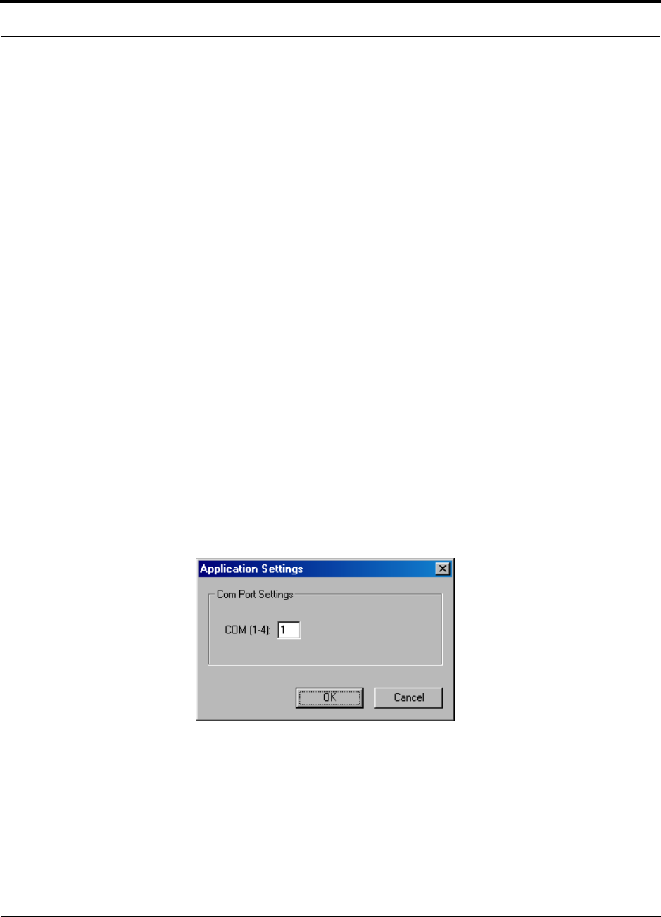
PN 8700-10 Help Hot Line (U.S. only): 1-800-530-9960 7-11
620003-0
PRELIMINARY PC/Laptop Requirements
AdminManager Operation Modes
You can choose one of four operation modes from the AdminManager Start window.
• Section 7.2 Installation Wizard . . . . . . . . . . . . . . . . . . . . . . . . . . . . . . . . . . 7-12
Select this option when you are installing a system or a Main Hub for the first time.
• Section 7.3 Configuration & Maintenance Panel . . . . . . . . . . . . . . . . . . . 7-24
• Section 7.3.2 Options when Connected Locally . . . . . . . . . . . . . . . . . . 7-28
Select this option when you want to perform specific tasks, such as perform the
system test and set system parameters, or check the status of an operating sys-
tem. All options are available when you are connected locally.
• Section 7.3.3 Read-Only Options when Connected Remotely . . . . . . . 7-33
The Configuration Panel is displayed in a read-only state. When you are con-
nected remotely there are a limited number of options available. The options let
you check the status of the system and determine if a site visit is required. (This
is the only operation mode you can choose when you are connected remotely.)
• Section 7.4 Upgrading Firmware . . . . . . . . . . . . . . . . . . . . . . . . . . . . . . . . 7-37
Select this option when you are upgrading a component’s firmware.
Buttons
• Settings
Clicking the SETTINGS button displays the Application Setting dialog box in which
you enter the communications port number that the modem will connect to for
remote monitoring and that the PC will use for connecting directly to a Main Hub
•Run
Depending on the operation option that you selected, clicking the RUN button dis-
plays the Step 1 panel of the Installation Wizard, the Configuration & Maintenance
window, or the Firmware Update window.
•Quit
Clicking the QUIT button stops the AdminManager and closes the panel.

Installing and Using the AdminManager Software PRELIMINARY
7-12 InterReach Unison User Guide and Reference Manual PN 8700-10
620003-0
7.2 Installation Wizard
Use the Installation Wizard when you are installing a new system or a new Main Hub
to a system. Installation consists of four steps; each one is displayed in a separate
panel of the Wizard.
• Section 7.2.1 Step 1: Verify Hardware . . . . . . . . . . . . . . . . . . . . . . . . . . . . . . 7-13
• Section 7.2.2 Step 2: Set Operation Band . . . . . . . . . . . . . . . . . . . . . . . . . . . . 7-15
• Section 7.2.3 Step 3: Configure System Parameters . . . . . . . . . . . . . . . . . . . . 7-19
• Section 7.2.4 Step 4: Final System Test . . . . . . . . . . . . . . . . . . . . . . . . . . . . . 7-21
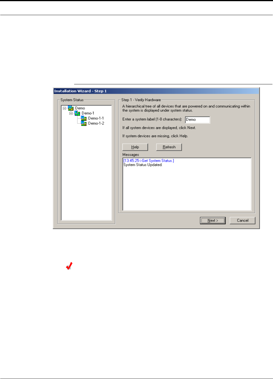
PN 8700-10 Help Hot Line (U.S. only): 1-800-530-9960 7-13
620003-0
PRELIMINARY Step 1: Verify Hardware
7.2.1 Step 1: Verify Hardware
During this step, the AdminManager software is in a listening mode. The Main Hub
detects downstream units (Expansion Hubs and RAUs) and automatically reports the
system configuration, which AdminManager displays as a configuration tree in the
System Status pane of the Step 1 panel.
Figure 7-3 Step 1: Verify Hardware Panel
Verify Hardware Configuration
1. Enter a system label (up to 8 characters) in the System Label text box.
This label is assigned to the Main Hub and appears in the System Status tree.
2. Click the NEXT button when the configuration is displayed correctly in the System
Status pane.
The Main Hub automatically reports any change in system status to the Admin-
Manager, which automatically updates the System Status tree.

Installing and Using the AdminManager Software PRELIMINARY
7-14 InterReach Unison User Guide and Reference Manual PN 8700-10
620003-0
7.2.1.1 Description of Step 1 Panel
Panes
• System Status
A hierarchical tree of detected system components is displayed in the System
Status pane. See Section 7.5 on page 7-38 for more information about the System
Status tree.
•Messages
Status and error messages are displayed in the Messages pane. If the status is okay,
the NEXT button is selectable.
Command Buttons
•Help
Clicking the HELP button displays the Unison Hardware Troubleshooting Guide.
•Refresh
Clicking the REFRESH button issues a query status command to the Main Hub and
the System Status tree is updated. Also, any disconnect status is cleared. While the
Main Hub does report system status to the AdminManager automatically, you can
use this button to force an update if communications fail or if there has been a sta-
tus change that is not showing in the System Status tree.
•Next
Clicking the NEXT button displays the Installation Wizard Step 2 panel.
•Cancel
Clicking the CANCEL button quits the Installation Wizard and displays the Admin-
Manager Start window (Figure 7-2).
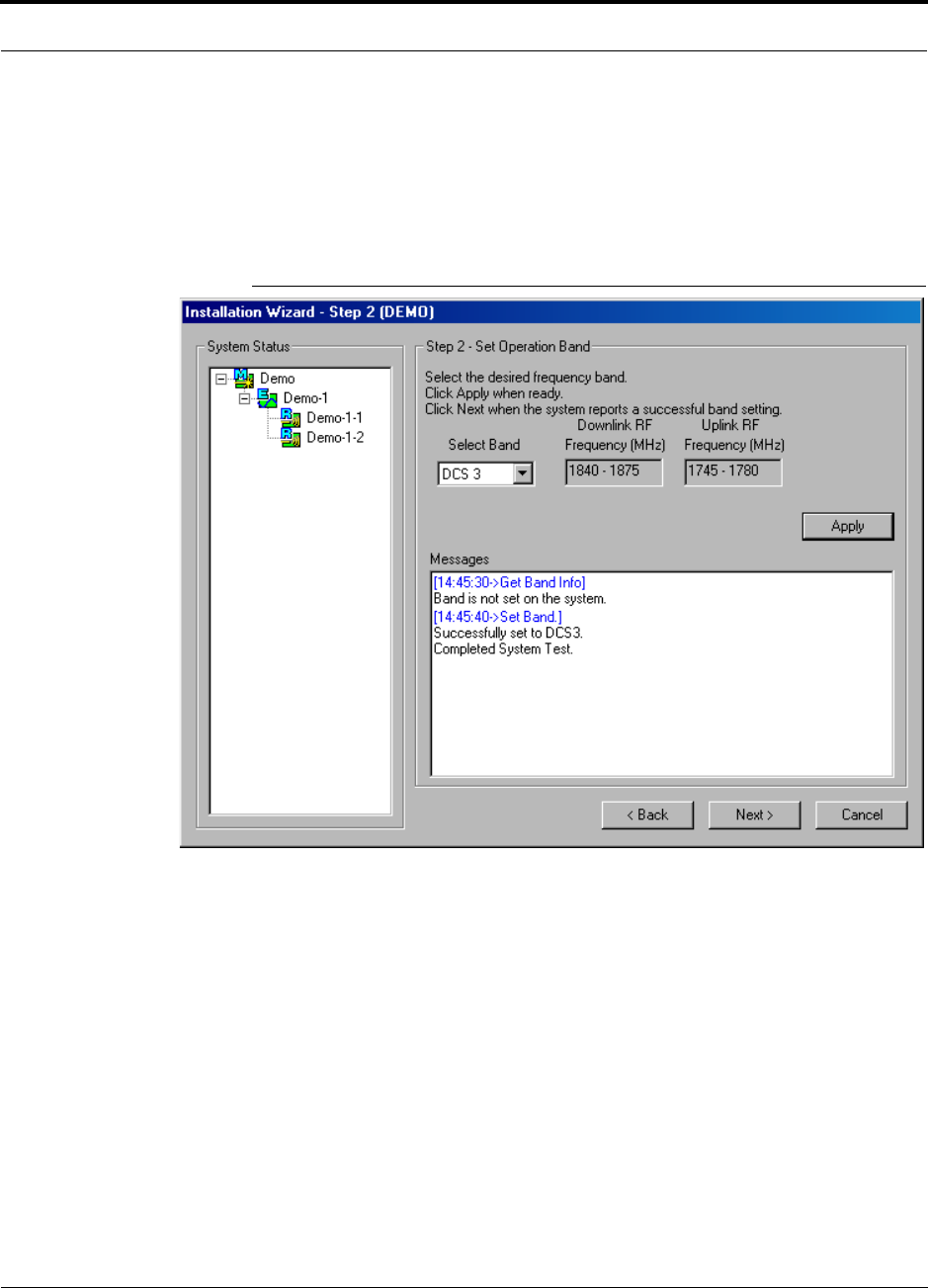
PN 8700-10 Help Hot Line (U.S. only): 1-800-530-9960 7-15
620003-0
PRELIMINARY Step 2: Set Operation Band
7.2.2 Step 2: Set Operation Band
The Main and Expansion Hubs are manufactured and shipped without a band of opera-
tion programmed into them. The RAUs, on the other hand, are manufactured to a spe-
cific band or set of bands. In order for the system to perform, you must program the
Main and Expansion Hubs to the band that the downstream RAUs are intended for.
Figure 7-4 Step 2: Set Operation Band

Installing and Using the AdminManager Software PRELIMINARY
7-16 InterReach Unison User Guide and Reference Manual PN 8700-10
620003-0
Set Operation Band
1. Select a band from the Select Band drop-down list box.
2. Click the APPLY button.
3. Click the NEXT button if:
a. The configuration is displayed correctly in the System Status pane.
b. There are no error messages in the Messages pane.
If a band setting error message is displayed, you can:
1. Disconnect the unit from the system.
2. Click the BACK button to return to Step 1.
3. Click the REFRESH button to clear the disconnected unit.
4. Click the NEXT button to continue to Step 2.
NOTE: “Band not initialized” faults can only be cleared by performing Step 2. The
Configuration & Maintenance panel does not provide a way to clear these faults.

PN 8700-10 Help Hot Line (U.S. only): 1-800-530-9960 7-17
620003-0
PRELIMINARY Step 2: Set Operation Band
7.2.2.1 Description of Step 2 Panel
Panes
• System Status
A hierarchical tree of detected system components is displayed in the System Sta-
tus pane. See Section 7.5 on page 7-38 for more information about the System Sta-
tus tree.
• Messages
Status and error messages are displayed in the Messages pane. If the status is okay,
the NEXT button is selectable.
Drop-Down List Box
• Select Band
Choose from:
Unison
Band
RF Passband
Downlink (MHz) Uplink (MHz)
Cellular 869–894 824–849
DCS1 1805–1842.5 1710–1747.5
DCS2 1842.5–1880 1747.5–1785
DCS3 1840–1875 1745–1780
EGSM 925–960 880–915
GSM 935–960 890–915
iDEN 851–869 806–824
PCS A&D 1930–1950 1850–1870
PCS B&E 1945–1965 1865–1885
PCS D&B 1950–1970 1870–1890
PCS E&F 1965–1975 1885–1895
PCS F&C 1970–1990 1890–1910
UMTS 1 2110–2145 1920–1955
UMTS 2 2125–2160 1935–1970
UMTS 3 2135–2170 1945–1980

Installing and Using the AdminManager Software PRELIMINARY
7-18 InterReach Unison User Guide and Reference Manual PN 8700-10
620003-0
Command Buttons
• Apply
Clicking the APPLY button issues the set band command to the Main Hub and all
downstream components.
In order for the system to complete the band configuration, the factory-set band of
all the attached RAUs must match the band command issued by the AdminMan-
ager software. If the band command matches the RAU’s, then the system band is
set. If the band command does not match, the command is rejected and a “Set band
error” message for that RAU is displayed.
•Back
Clicking the BACK button returns AdminManager to the Step 1 panel.
•Next
Clicking the NEXT button displays the Installation Wizard Step 3 panel. This button
is selectable only when the APPLY function is successful.
•Cancel
Clicking the CANCEL button quits the Installation Wizard and displays the Admin-
Manager Start window (Figure 7-2).
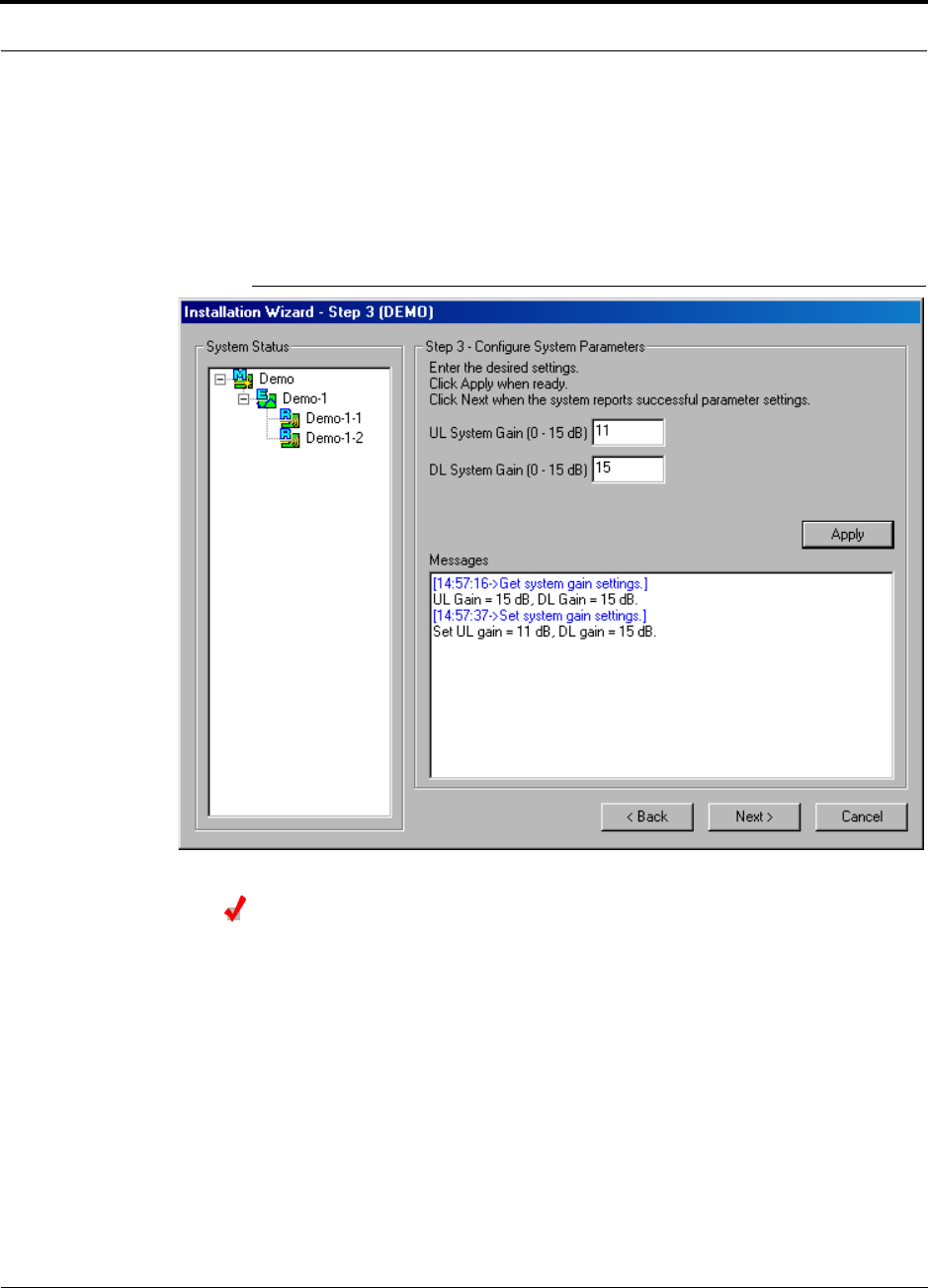
PN 8700-10 Help Hot Line (U.S. only): 1-800-530-9960 7-19
620003-0
PRELIMINARY Step 3: Configure System Parameters
7.2.3 Step 3: Configure System Parameters
From this panel, you can set uplink and downlink system gain from 0 dB to 15 dB in
1 dB steps. By default, the UL and DL System Gain is set at 15 dB. Current hardware
settings are shown in the text boxes when the panel is first displayed. Figure 7-5
shows the display after the UL System Gain was changed to 11 dB.
Figure 7-5 Step 3: Configure System Parameters
Configure System Parameters
If you want to keep the values as they are initially displayed, click the NEXT button.
If you want to change the values:
1. Enter a value in the UL System Gain text box, if desired.
2. Enter a value in the DL System Gain text box, if desired.
3. Click the APPLY button when you are ready.
4. Click the NEXT button if:
a. The configuration is displayed correctly in the System Status pane.
b. There are no error messages in the Messages pane.

Installing and Using the AdminManager Software PRELIMINARY
7-20 InterReach Unison User Guide and Reference Manual PN 8700-10
620003-0
7.2.3.1 Description of Step 3 Panel
Panes
• System Status
A hierarchical tree of detected system components is displayed in the System Sta-
tus pane. See Section 7.5 on page 7-38 for more information about the System Sta-
tus tree.
•Messages
Status and error messages are displayed in the Messages pane. If the status is okay,
the NEXT button is selectable.
Text Boxes
•UL System Gain and DL System Gain
Both the uplink and the downlink system gain can be adjusted from 15 dB to 0 dB
in 1 dB increments using these text boxes.
Command Buttons
• Apply
Clicking the APPLY button sets the selected value.
•Back
Clicking the BACK button returns AdminManager to the Step 2 panel.
•Next
Clicking the NEXT button displays the Installation Wizard Step 4 panel.
•Cancel
Clicking the CANCEL button quits the Installation Wizard and displays the Admin-
Manager Start window (Figure 7-2).
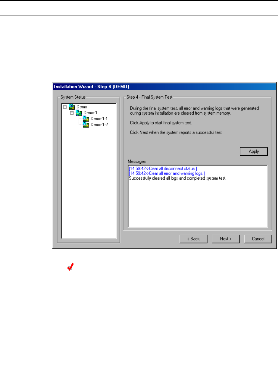
PN 8700-10 Help Hot Line (U.S. only): 1-800-530-9960 7-21
620003-0
PRELIMINARY Step 4: Final System Test
7.2.4 Step 4: Final System Test
This step performs an end-to-end RF path functional test that includes cable length
estimation and system gain refinement. Any disconnect status is cleared and all fault
logs are cleared.
Figure 7-6 Step 4: Final System Test
Perform Final System Test
1. Click the APPLY button if the configuration is displayed correctly in the System
Status pane.
2. Click the NEXT button when a successful test message is displayed in the Mes-
sages pane.
You can use the BACK button to return to previous steps and make changes if an error
is displayed in the Messages pane.

Installing and Using the AdminManager Software PRELIMINARY
7-22 InterReach Unison User Guide and Reference Manual PN 8700-10
620003-0
7.2.4.1 Description of Step 4 Panel
Panes
• System Status
A hierarchical tree of detected system components is displayed in the System Sta-
tus pane. See Section 7.5 on page 7-38 for more information about the System Sta-
tus tree.
•Messages
Status and error messages are displayed in the Messages pane. If the status is okay,
the NEXT button is selectable.
Command Buttons
• Apply
Clicking the APPLY button starts the final system test.
•Back
Clicking the BACK button returns AdminManager to the Step 3 panel.
•Next
Clicking the NEXT button displays the Installation Wizard Finish panel. This button
is selectable only when the APPLY function is successful.
•Cancel
Clicking the CANCEL button quits the Installation Wizard and displays the Admin-
Manager Start window (Figure 7-2).
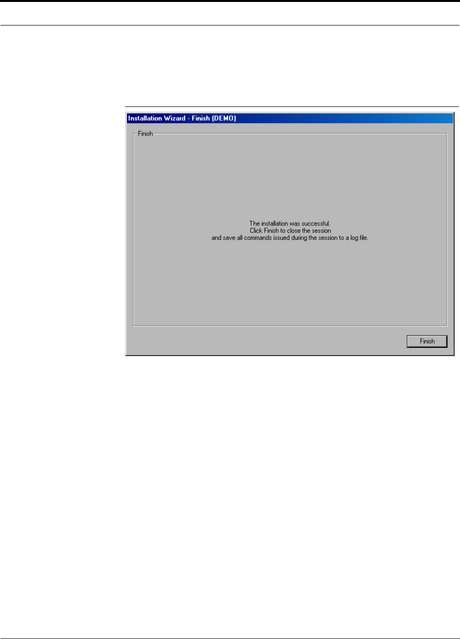
PN 8700-10 Help Hot Line (U.S. only): 1-800-530-9960 7-23
620003-0
PRELIMINARY Finish Panel
7.2.5 Finish Panel
The Finish panel is displayed when the final system test is successfully completed.
Figure 7-7 Finish Panel
1. Click the FINISH button.
A Save As dialog box is displayed.
2. Specify a file name and where to save the configuration file.
The information that is stored in the configuration file is required for the As-Built
Documentation.
7.2.5.1 Description of Finish Panel
Command Button
• Finish
Clicking the FINISH button displays a Save As dialog box for saving the configura-
tion file and then quits the session.
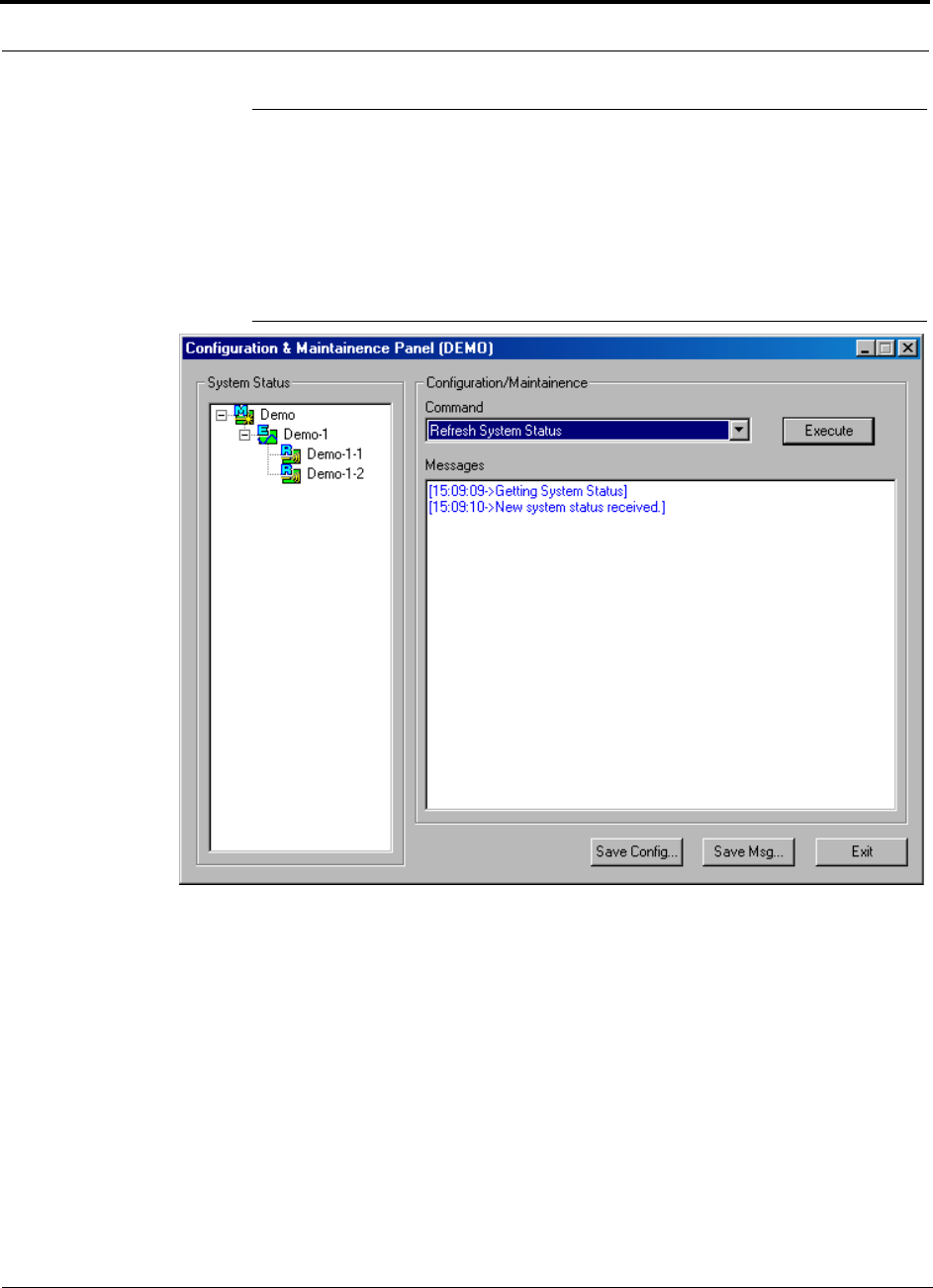
Installing and Using the AdminManager Software PRELIMINARY
7-24 InterReach Unison User Guide and Reference Manual PN 8700-10
620003-0
7.3 Configuration & Maintenance Panel
The Configuration & Maintenance Panel is used after the initial installation of a sys-
tem. From this panel you can check status of the system, get current errors and warn-
ings, get information about a particular unit in the system, set system parameters, and
perform a system test, for example.
Figure 7-8 Configuration & Maintenance Window

PN 8700-10 Help Hot Line (U.S. only): 1-800-530-9960 7-25
620003-0
PRELIMINARY Window Description
7.3.1 Window Description
Panes
• System Status
A hierarchical tree of detected system components is displayed in the System Sta-
tus pane. See Section 7.5 on page 7-38 for more information about the System Sta-
tus tree.
• Messages
Status and error messages are displayed in the Messages pane.
Drop-Down List Box
Table 7-1 Configuration and Maintenance Window Options
Connection
OptionLocal Remote
Advanced RAU Settings
Clear All Disconnect Status
Command Unit In-Service
Command Unit Out-of-Service
Get Current Errors
Get Current Warnings
Get System Parameters
Get Unit Info
Refresh System Status
Set Callback Number
Set Contact Sense Properties
Set System Parameters
System Test
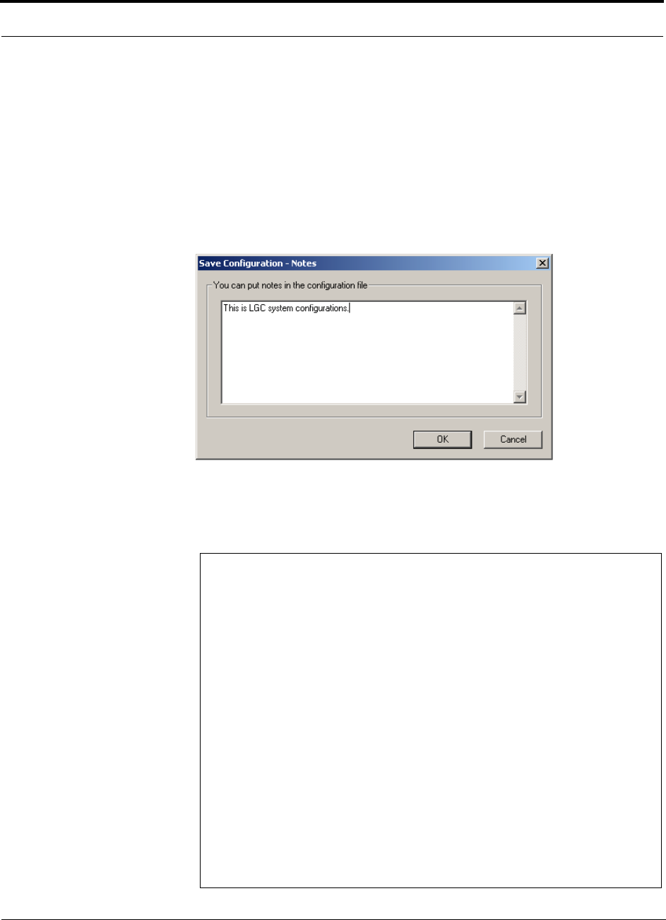
Installing and Using the AdminManager Software PRELIMINARY
7-26 InterReach Unison User Guide and Reference Manual PN 8700-10
620003-0
Command Buttons
• Execute
Clicking the EXECUTE button starts the command that is selected in the Command
list box.
•Save Config
Clicking the SAVE CONFIG button displays the Save Configuration Notes dialog
box. Any additional information that you type into the text box is saved at the top
of the configuration file.
After you click OK in this dialog box, the Save As dialog box is displayed, in
which you specify the name of the file and where to save the configuration file.
Following is an example configuration file that includes notes:
Begin Notes *******************************************
LGC HQ
05/23/01 MH configuration L010MH11
System configuration
End Notes *********************************************
Frequency Band is DCS Low.
System Gain: UL = 12 dB, DL=4dB.
Callback Number is 1234567.
System label is LGC.
Main Hub Information:
Serial Number: L010BMH1
Part Number: 7405101
Revision Number: 03
Firmware Revision: 010526
Expansion Hub LGC-1 Information:
Serial Number: L010BEH9
Part Number: 7405101
Revision Number: 03
Firmware Revision: 010513
RAU LGC-1-5 Information:
Serial Number: L010BRU1
Part Number: 7405101
Revision Number: 03
Firmware Revision: 010021

PN 8700-10 Help Hot Line (U.S. only): 1-800-530-9960 7-27
620003-0
PRELIMINARY Window Description
• Save Msg
Selecting the SAVE MSG button displays the Save As dialog box in which you spec-
ify the name of the file and where to save the contents of the Message text box.
•Exit
Selecting the EXIT button quits the session and displays the AdminManager Start
window (Figure 7-2).
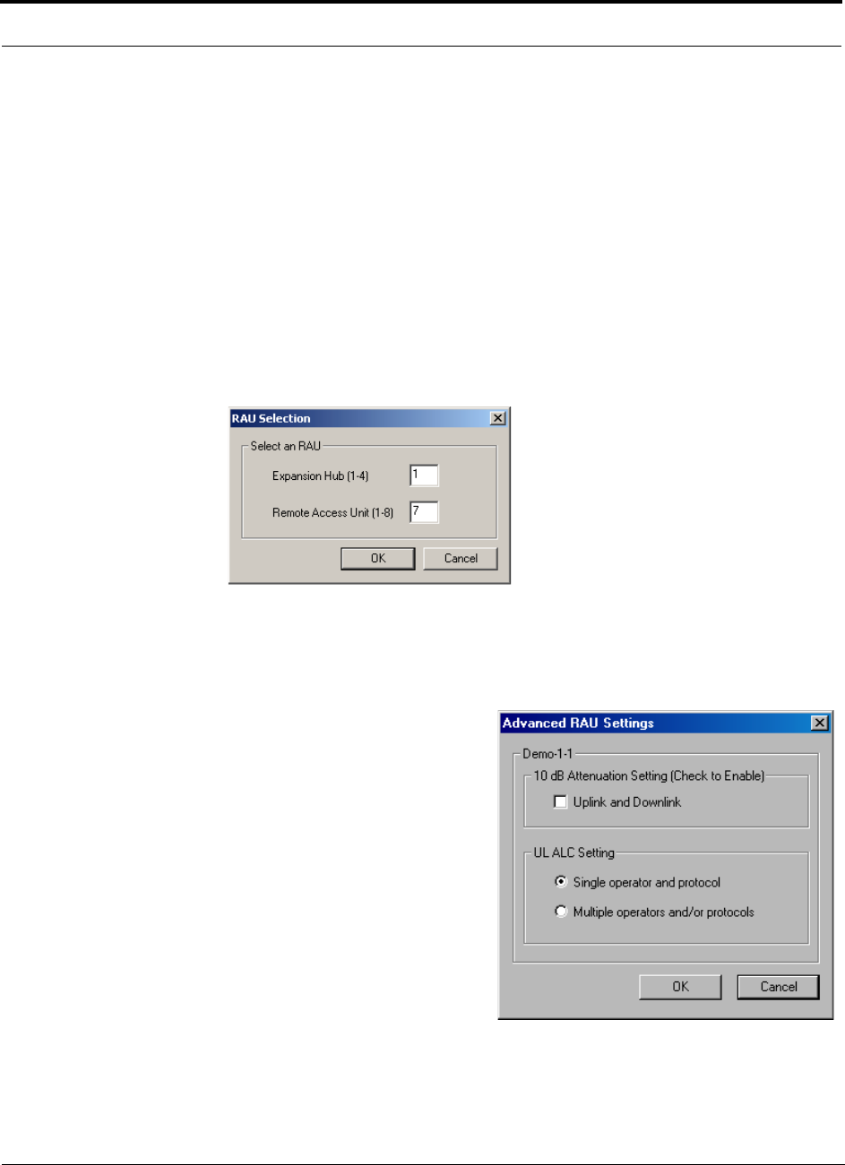
Installing and Using the AdminManager Software PRELIMINARY
7-28 InterReach Unison User Guide and Reference Manual PN 8700-10
620003-0
7.3.2 Options when Connected Locally
When you are locally connected to the Main Hub, you can choose the following
options in addition to those listed in Section 7.3.3, “Read-Only Options when Con-
nected Remotely,” on page 7-33 (also, see Table 7-1 on page 7-25).
Advanced RAU Settings
• Set uplink and downlink 10 dB attenuation for an individual RAU
Refer to “Using the 10 dB Attenuation Setting” on page 7-29 for a description
of this setting.
• Select a UL ALC setting for an individual RAU
Refer to “Using the Uplink ALC Setting” on page 7-30 for a description of this
setting.
1. Enter the Expansion Hub number and the
RAU number in the text boxes on the RAU
Selection dialog box and click OK.
The Advanced RAU Settings dialog box is
displayed.”
In the Advanced RAU Settings example
shown below, Demo-1-1 indicates that RAU
number 1 that is connected to Expansion
Hub number 1 in the “Demo” Main Hub sys-
tem is selected.
2. Select the Uplink and Downlink check box
to enable the 10 dB attenuation setting.
3. Select a radio button from the UL ALC Set-
ting list.

PN 8700-10 Help Hot Line (U.S. only): 1-800-530-9960 7-29
620003-0
PRELIMINARY Options when Connected Locally
Using the 10 dB Attenuation Setting
By selecting the Uplink and Downlink checkbox in the Advanced RAU Settings dia-
log box, the uplink and downlink signals in the individual RAU, which you specified
in the RAU Selection dialog box, are both reduced by 10 dB. One reason you may
want to use this setting is to reduce the RAU’s output power when an RAU is located
near an exterior wall of a building and its RF signal is going beyond the wall to the
outside of the building, where it can negatively affect the outdoor macro system.
The following table shows some examples of how the 10 dB attenuation setting
affects coverage distance. These examples assume a 0 dB gain system, a 3 dBi gain
antenna, and the difference between a –85 dB and a –75 dB design.
You can use the following formula to calculate the reduction in distance covered.
•d
orig = original distance
•d
new = new distance with 10 dB attenuation enabled
• PLS = path loss slope [dB]
dnew = (10–10/PLS)dorig
Examples:
dnew = 0.31 dorig for PLS = 20 dB (free space)
dnew = 0.46 dorig for PLS = 30 dB
Frequency Environment Reduction in Coverage Distance
800 MHz Open, like a parking garage 24 meters (80 feet)
800 MHz Heavily walled, like a Hospital 12.5 meters (41 feet)
1900 MHz Open, like a parking garage 24 meters (80 feet)
1900 MHz Heavily walled, like a Hospital 9 meters (30 feet)

Installing and Using the AdminManager Software PRELIMINARY
7-30 InterReach Unison User Guide and Reference Manual PN 8700-10
620003-0
Using the Uplink ALC Setting
Uplink automatic level control (UL ALC) circuitry within the RAU provides auto-
matic level control on high-power signals in the uplink path. This functionality is
required to prevent compression caused by a single or multiple wireless devices that
are in very close proximity to an RAU. Compression causes signal degradation and,
ultimately, bit errors, and should be prevented. Two settings are available to optimize
UL ALC performance:
•Single Operator and Protocol: Use when only one operator and protocol is
on-the-air within the Unison system’s configured and adjacent frequency bands.
•Multiple Operators and/or Protocols: Use when more than one operator and/or
protocol is present in the Unison system’s frequency and adjacent frequency
bands.
The following table shows the frequency bands that are adjacent to the bands that the
system is configured for.
Table 7-2 Frequency Bands Adjacent to System Configured Bands
System
Configuration Adjacent Bands
iDEN Cellular
Cellular iDEN
PCS AD PCS B
PCS DB PCS A, PCS E
PCS BE PCS D, PCS F
PCS EF PCS B, PCS C
PCS FC PCS E
GSM –
EGSM –
DCS 1 DCS 2
DCS 2 DCS 1, DCS 3
DCS 3 –
UMTS 1 UMTS 2, UMTS 3
UMTS 2 UMTS 1, UMTS 3
UMTS 3 UMTS 1, UMTS 2
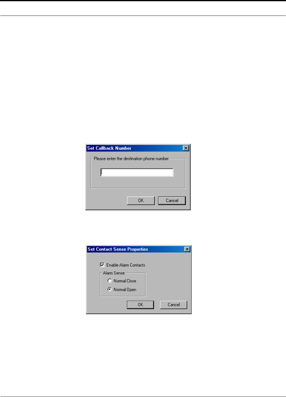
PN 8700-10 Help Hot Line (U.S. only): 1-800-530-9960 7-31
620003-0
PRELIMINARY Options when Connected Locally
•Clear All Disconnect Status: clears a port disconnect fault when an Expansion
Hub or an RAU is disconnected and will not be re-connected.
•Command Unit In-Service: returns a unit to service that was previously removed
from service; restores a component to the system’s alarm monitoring; displays the
unit lock, unit not system tested, or normal operation icon.
•Command Unit Out-of-Service: removes a unit, and all of its downstream units,
from service, there is no RF transmission; lets you temporarily remove a compo-
nent from the system’s alarm monitoring; displays unit “lock” icon.
•Set Callback Number: displays a dialog box in which you enter the phone num-
ber that the system uses to communicate with OpsConsole users. You can use up to
64 characters: 0 through 9, and the comma (,) for a pause. Leave the field blank if
you do not want the unit to call out. Refer to your modem documentation for other
characters that you can use. To disable callback, leave the text box empty.
•Set Contact Sense Properties: enables/disables the external sensing of either nor-
mally open or normally closed contact closures; displays “contact sense alarm” or
“contact sense okay” icon.
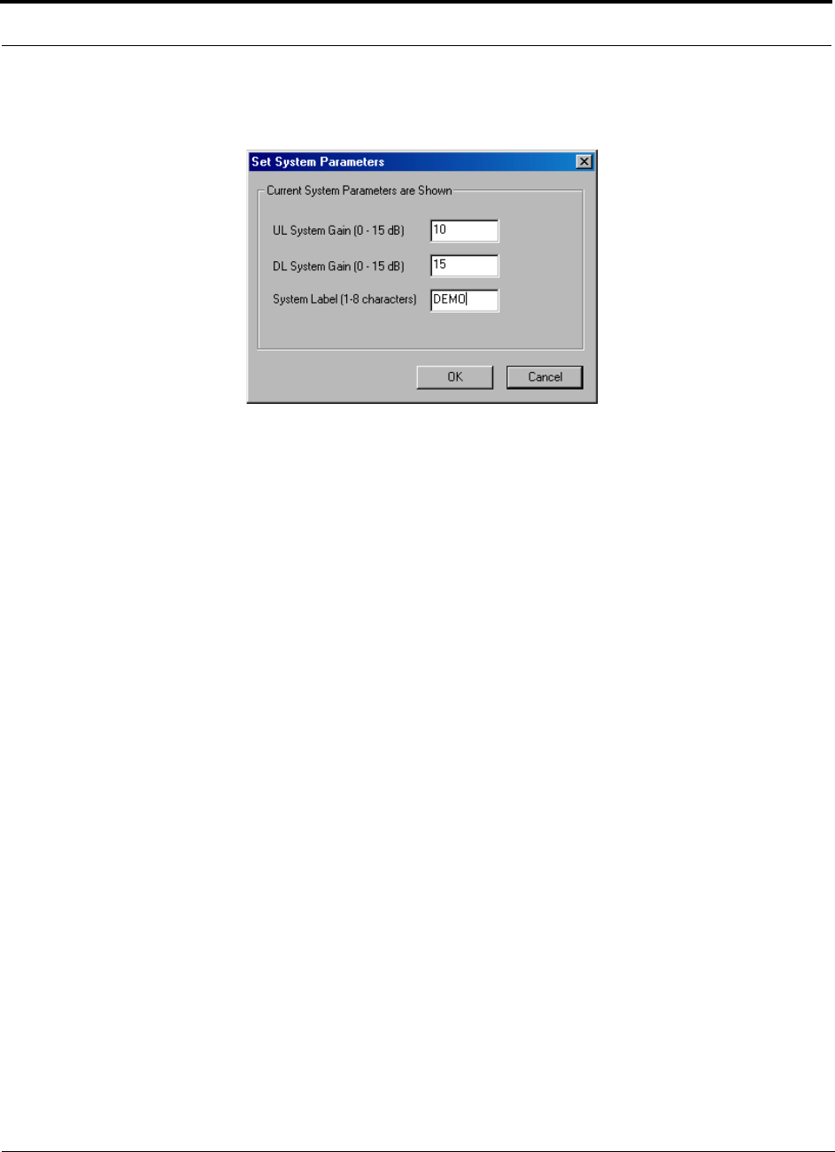
Installing and Using the AdminManager Software PRELIMINARY
7-32 InterReach Unison User Guide and Reference Manual PN 8700-10
620003-0
•Set System Parameters: displays a dialog box from which you select uplink and
downlink gain settings, and/or specify a system label.
•System Test: An end-to-end RF path functional test that includes cable length esti-
mation and system gain refinement is performed during the system test. System
operation is suspended while the test is being performed.
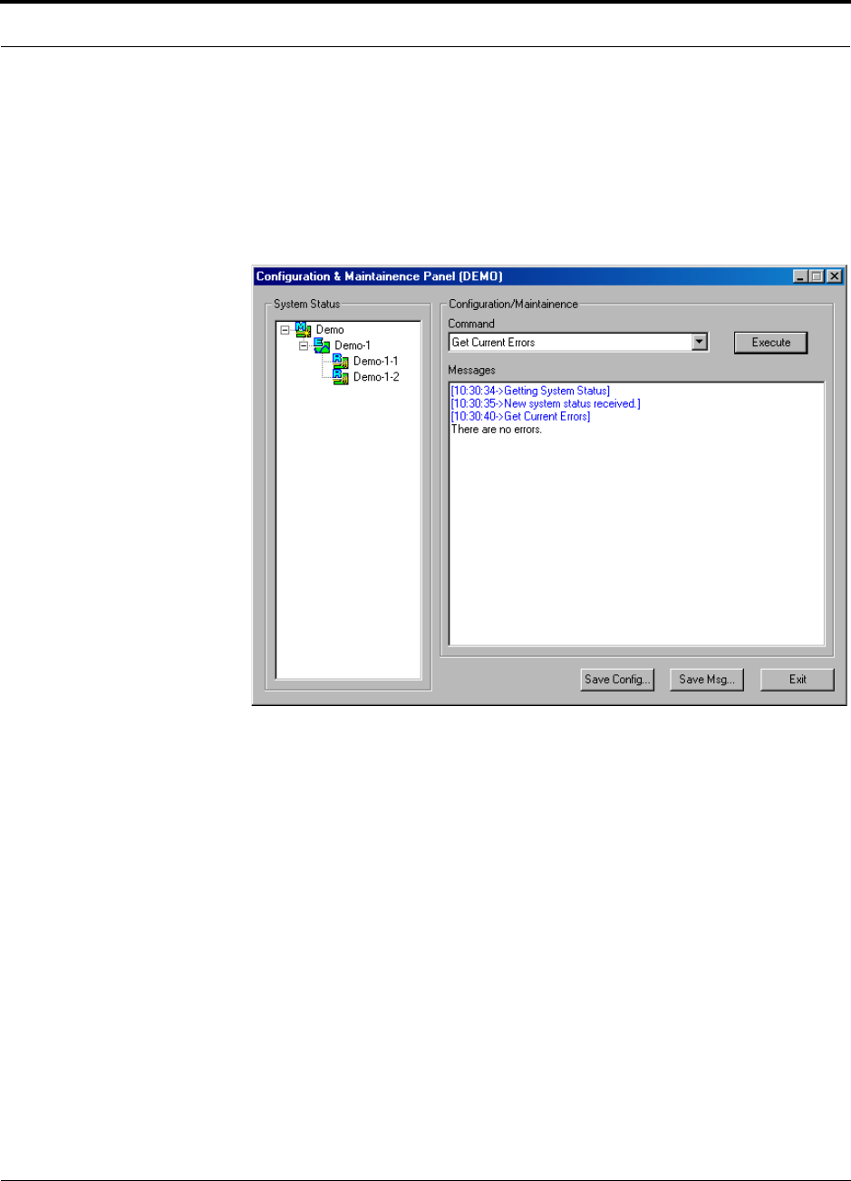
PN 8700-10 Help Hot Line (U.S. only): 1-800-530-9960 7-33
620003-0
PRELIMINARY Read-Only Options when Connected Remotely
7.3.3 Read-Only Options when Connected Remotely
You can only choose read-only options and view system status when you are
remotely connected to the Main Hub. You cannot set parameters or change system
configuration remotely. (See Table 7-1 on page 7-25.)
•Get Current Errors: displays the highest priority error with a recommendations
for resolving it
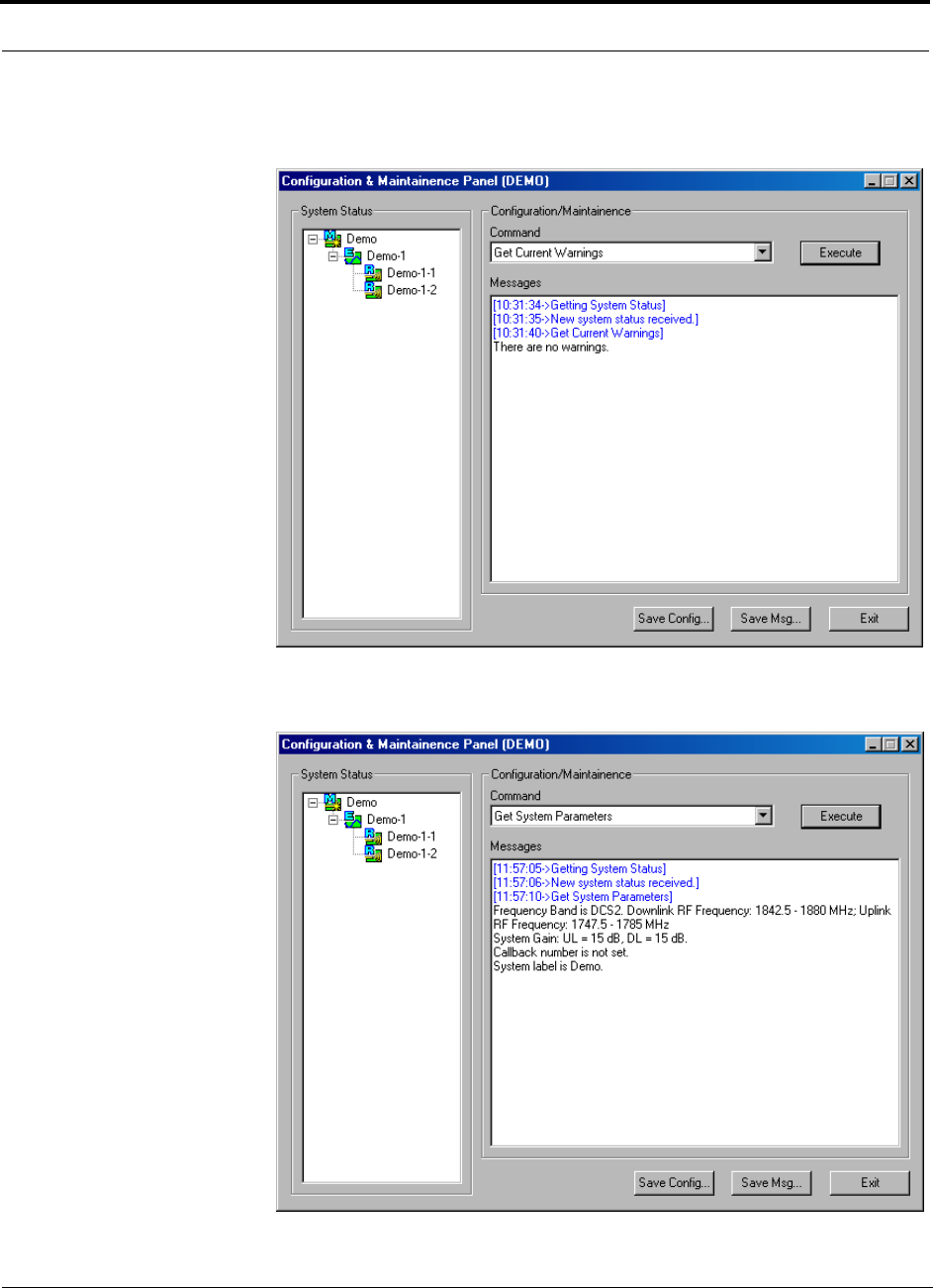
Installing and Using the AdminManager Software PRELIMINARY
7-34 InterReach Unison User Guide and Reference Manual PN 8700-10
620003-0
•Get Current Warnings: displays the highest priority warning with a recommen-
dations for resolving it
•Get System Parameters: displays the frequency band, callback number, uplink
and downlink system gain, and system label
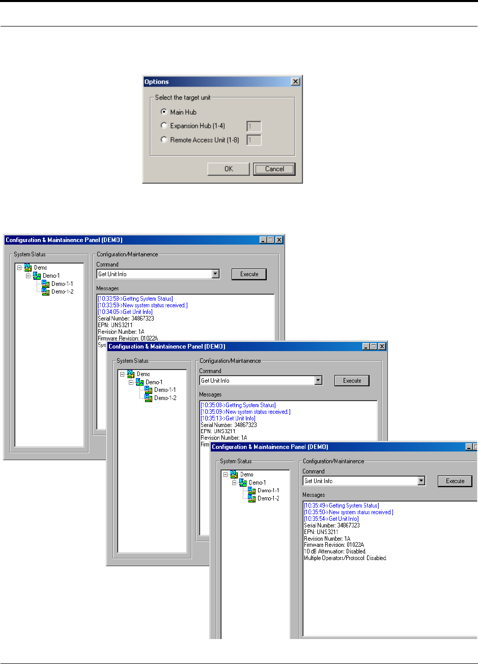
PN 8700-10 Help Hot Line (U.S. only): 1-800-530-9960 7-35
620003-0
PRELIMINARY Read-Only Options when Connected Remotely
•Get Unit Info: displays the Options dialog box in which you select a unit.
Select a unit and click the OK button to display that unit’s serial number, part num-
ber, revision number and firmware version. Additionally, the advanced settings for
the RAU are displayed when RAU information is requested.
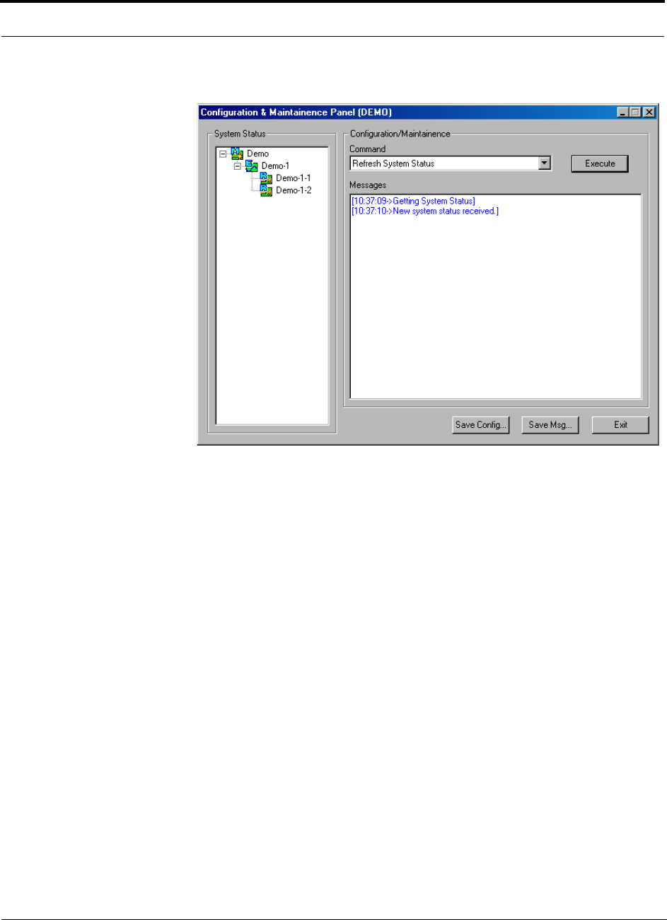
Installing and Using the AdminManager Software PRELIMINARY
7-36 InterReach Unison User Guide and Reference Manual PN 8700-10
620003-0
•Refresh System Status: requests system status and updates the System Status tree
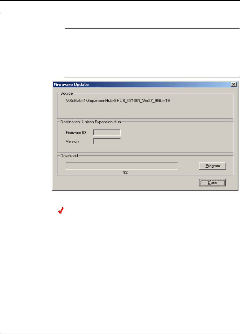
PN 8700-10 Help Hot Line (U.S. only): 1-800-530-9960 7-37
620003-0
PRELIMINARY Upgrading Firmware
7.4 Upgrading Firmware
The firmware update program automatically detects which unit the firmware is
intended for and displays the firmware ID and version number in the Firmware
Update window, as shown in the following figure.
Figure 7-9 Firmware Update Window
Updating Firmware
1. Copy the firmware program to the PC.
2. Start AdminManager and select the Firmware Update radio button on the Start
window, and then click run.
An Open File dialog box is displayed.
3. Choose the .m19 file you want to open from the Open File dialog box and click
OPEN.
The firmware ID and version number are displayed in the Firmware Update win-
dow.
4. Click the PROGRAM button to start the download.
This button changes to CANCEL during the download, click it to stop the firmware
update.
5. Click the DONE button.
This button is enabled when the download is completed.
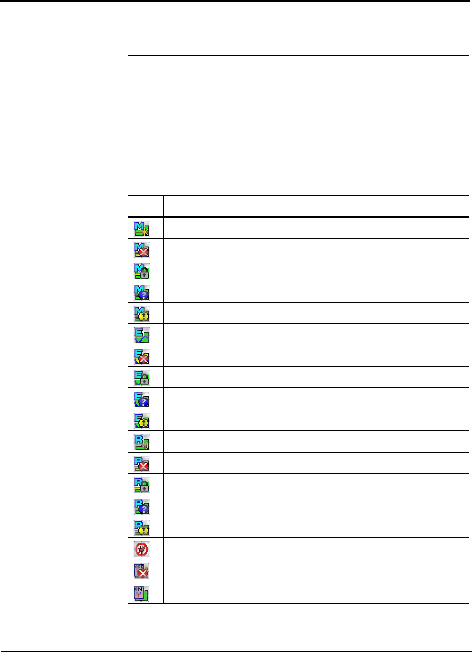
Installing and Using the AdminManager Software PRELIMINARY
7-38 InterReach Unison User Guide and Reference Manual PN 8700-10
620003-0
7.5 System Status Tree
A hierarchical tree of the detected system components is displayed in the System Sta-
tus pane.
7.5.1 System Status Tree Icons
The following table shows the icons that may appear in the System Status tree.
Table 7-3 System Status Tree Icons
Icon Description
Main Hub normal operation
Main Hub fault
Main Hub lock (unit and all downstream units are out-of-service)
Main Hub has not been system tested since last power on
Main Hub warning
Expansion Hub normal operation
Expansion Hub fault
Expansion Hub lock (unit and all downstream RAUs are out-of-service)
Expansion Hub has not been system tested since last power on
Expansion Hub warning
RAU normal operation
RAU fault
RAU lock
RAU has not been system tested since last power on
RAU warning
No communication
Contact sense alarm
Contact sense okay

PN 8700-10 InterReach Unison User Guide and Reference Manual 8-1
620003-0
PRELIMINARY
SECTION 8 Designing a Unison Solution
Designing a Unison solution is ultimately a matter of determining coverage and
capacity needs. This requires the following steps:
1. Determine the wireless service provider’s requirements.
This information is usually supplied by the service provider:
• Frequency (i.e., 850 MHz)
• Band (i.e., “A” band in the Cellular spectrum)
• Protocol (i.e., TDMA, CDMA, GSM, iDEN)
• Peak capacity requirement (this, and whether or not the building will be split
into sectors, determines the number of carriers that the system will have to
transmit)
• Design goal (RSSI, received signal strength at the wireless handset,
i.e., –85 dBm)
The design goal is always a stronger signal than the cell phone needs. It
includes inherent factors which will affect performance (see Section 8.4.1 on
page 8-33).
• RF source (base station or BDA), type of equipment if possible
2. Determine the power per carrier and input power from the base station or
BDA into the Main Hub: Section 8.1, “Maximum Output Power per Carrier
at RAU,” on page 8-3.
The maximum power per carrier is a function of the number of RF carriers, the
carrier headroom requirement, signal quality issues, regulatory emissions require-
ments, and Unison’s RF performance. The power per carrier decreases as the
number of carriers increases.
3. Determine the in-building environment: Section 8.2, “Estimating RF Cover-
age,” on page 8-19.
• Determine which areas of the building require coverage (entire building, public
areas, parking levels, etc.)

Designing a Unison Solution PRELIMINARY
8-2 InterReach Unison User Guide and Reference Manual PN 8700-10
620003-0
• Obtain floor plans to determine floor space of building and the wall layout of
the proposed areas to be covered. Floor plans will also be useful when you are
selecting antenna locations.
• If possible, determine the building’s construction materials (sheetrock, metal,
concrete, etc.)
• Determine type of environment
– Open layout (e.g., a convention center)
– Dense, close walls (e.g., a hospital)
– Mixed use (e.g., an office building with hard wall offices and cubicles)
4. Develop an RF link budget: Section 8.4, “Link Budget Analysis,” on page
8-32.
Knowing the power per carrier, you can calculate an RF link budget which is used
to predict how much propagation loss can be allowed in the system, while still
providing satisfactory performance throughout the area being covered. The link
budget is a methodical way to derive a “design goal”. If the design goal is pro-
vided in advance, the link budget is simply: allowable RF loss = max. power per
carrier – design goal.
5. Determine the appropriate estimated path loss slope that corresponds to the
type of building and its layout, and estimate the coverage distance for each
RAU: Section 8.2, “Estimating RF Coverage,” on page 8-19.
The path loss slope (PLS), which gives a value to the RF propagation characteris-
tics within the building, is used to convert the RF link budget into an estimate of
the coverage distance per antenna. This will help establish the Unison equipment
quantities you will need. The actual path loss slope that corresponds to the spe-
cific RF environment inside the building can also be determined empirically by
performing an RF site-survey of the building. This involves transmitting a cali-
brated tone for a fixed antenna and making measurements with a mobile antenna
throughout the area surrounding the transmitter.
6. Determine the items required to connect to the base station: Section 8.6,
“Connecting a Main Hub to a Base Station,” on page 8-47.
Once you know the quantities of Unison equipment you will use, you can deter-
mine the accessories (combiners/dividers, surge suppressors, repeaters, attenua-
tors, circulators, etc.) that are required to connect the system to the base station.
The individual elements that must be considered in designing a Unison solution are
discussed in the following sections.
PN 8700-10 Help Hot Line (U.S. only): 1-800-530-9960 8-3
620003-0
PRELIMINARY Maximum Output Power per Carrier at RAU
8.1 Maximum Output Power per Carrier at RAU
The following tables show the recommended maximum power per carrier out of the
RAU SMA connector for different frequencies, formats, and numbers of carriers.
These limits are dictated by RF signal quality and regulatory emissions issues. The
maximum input power to the Main Hub is determined by subtracting the system gain
from the maximum output power of the RAU. System gain is software selectable
from 0 dB to 15 dB in 1 dB steps. Additionally, both the uplink and downlink RAU
gain can be reduced by 10 dB.
Therefore, when you connect a Main Hub to a base station or repeater, the RF power
per carrier usually needs to be attenuated in order to avoid exceeding Unison’s max-
imum composite output power.
(reference to “composite” power. PS)
Refer to Section 8.7, “Designing for a Neutral Host System,” on page 8-51 when
combining frequencies or protocols on a single Main Hub.
WARNING: Exceeding the maximum input power could cause perma-
nent damage to the Main Hub.
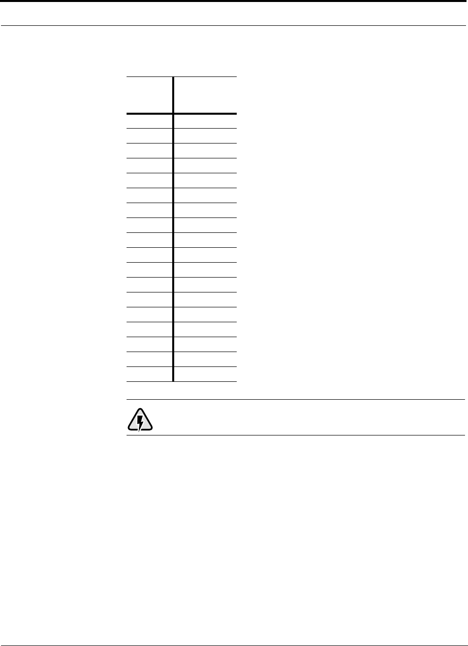
Designing a Unison Solution PRELIMINARY
8-4 InterReach Unison User Guide and Reference Manual PN 8700-10
620003-0
WARNING: For 800 MHz AMPS, do not exceed the maximum compos-
ite input power of 1W (+30 dBm) to the Main Hub at any time.
Table 8-1 800 MHz (AMPS) Power per Carrier
No. of
Carriers
Power per
Carrier
(dBm)
110.0
210.0
310.0
410.0
510.0
610.5
79.5
88.5
98.0
10 7.0
11 7.0
12 6.5
13 6.0
14 5.5
15 5.5
16 5.0
20 4.0
30 2.0

PN 8700-10 Help Hot Line (U.S. only): 1-800-530-9960 8-5
620003-0
PRELIMINARY Maximum Output Power per Carrier at RAU
WARNING: For 800 MHz TDMA, do not exceed the maximum compos-
ite input power of 1W (+30 dBm) to the Main Hub at any time.
Table 8-2 800 MHz (TDMA) Power per Carrier
No. of
Carriers
Power per
Carrier
(dBm)
110.0
210.0
310.0
410.0
510.0
610.0
79.5
88.5
98.0
10 7.5
11 7.0
12 6.5
13 6.5
14 6.0
15 5.5
16 5.5
20 4.5
30 2.5
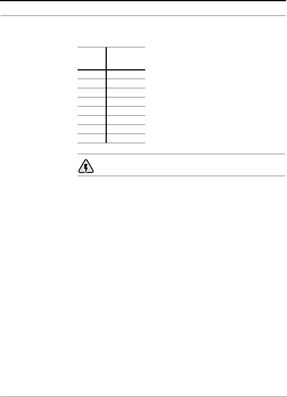
Designing a Unison Solution PRELIMINARY
8-6 InterReach Unison User Guide and Reference Manual PN 8700-10
620003-0
WARNING: For 800 MHz CDMA, do not exceed the maximum com-
posite input power of 1W (+30 dBm) to the Main Hub at any time.
Table 8-3 800 MHz (CDMA) Power per Carrier
No. of
Carriers
Power per
Carrier
(dBm)
116.0
213.5
312.0
411.0
510.0
69.5
78.5
88.0

PN 8700-10 Help Hot Line (U.S. only): 1-800-530-9960 8-7
620003-0
PRELIMINARY Maximum Output Power per Carrier at RAU
WARNING: For 800 MHz iDEN, do not exceed the maximum compos-
ite input power of 1W (+30 dBm) to the Main Hub at any time.
Table 8-4 800 MHz (iDEN) Power per Carrier
No. of
Carriers
Power per
Carrier
(dBm)
110.0
210.0
310.0
410.0
59.0
68.0
77.0
86.5
96.0
10 5.5
11 5.0
12 4.5
13 4.0
14 4.0
15 3.5
16 3.0
20 2.0
30 0.5

Designing a Unison Solution PRELIMINARY
8-8 InterReach Unison User Guide and Reference Manual PN 8700-10
620003-0
WARNING: For 900 MHz GSM or EGSM, do not exceed the maximum
composite input power of 1W (+30 dBm) to the Main Hub at any time.
Table 8-5 900 MHz (GSM or EGSM) Power per Carrier
No. of
Carriers
Power per
Carrier
(dBm)
110.0
210.0
310.0
410.0
59.0
68.5
78.0
87.5
97.0
10 6.5
11 6.5
12 6.0
13 5.5
14 5.5
15 5.0
16 5.0

PN 8700-10 Help Hot Line (U.S. only): 1-800-530-9960 8-9
620003-0
PRELIMINARY Maximum Output Power per Carrier at RAU
WARNING: For 900 MHz EDGE, do not exceed the maximum compos-
ite input power of 1W (+30 dBm) to the Main Hub at any time.
Table 8-6 900 MHz (EDGE) Power per Carrier
No. of
Carriers
Power per
Carrier
(dBm)
110.0
210.0
310.0
410.0
59.0
68.5
78.0
87.5
97.0
10 6.5
11 6.5
12 6.0
13 5.5
14 5.5
15 5.0
16 5.0

Designing a Unison Solution PRELIMINARY
8-10 InterReach Unison User Guide and Reference Manual PN 8700-10
620003-0
WARNING: For 1800 MHz GSM, do not exceed the maximum compos-
ite input power of 1W (+30 dBm) to the Main Hub at any time.
Table 8-7 1800 MHz (GSM) Power per Carrier
No. of
Carriers
Power per
Carrier
(dBm)
110.0
210.0
310.0
410.0
510.0
69.5
78.5
87.5
97.0
10 6.5
11 6.0
12 5.5
13 5.0
14 5.0
15 4.5
16 4.0
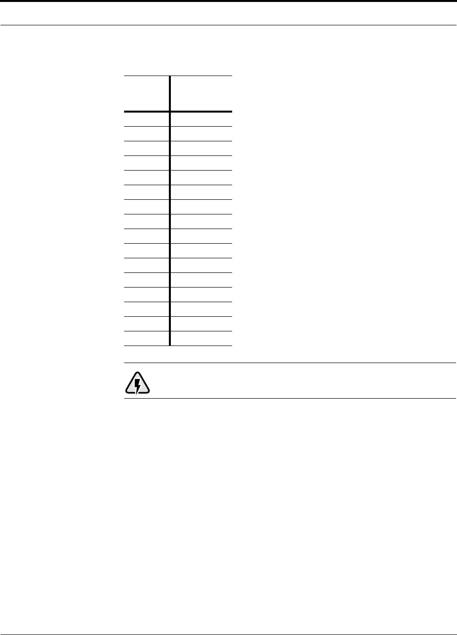
PN 8700-10 Help Hot Line (U.S. only): 1-800-530-9960 8-11
620003-0
PRELIMINARY Maximum Output Power per Carrier at RAU
WARNING: For 1800 MHz EDGE, do not exceed the maximum com-
posite input power of 1W (+30 dBm) to the Main Hub at any time.
Table 8-8 1800 MHz (EDGE) Power per Carrier
No. of
Carriers
Power per
Carrier
(dBm)
110.0
210.0
310.0
410.0
59.0
68.0
77.5
86.5
96.0
10 5.5
11 5.0
12 4.5
13 4.5
14 4.0
15 3.5
16 3.5
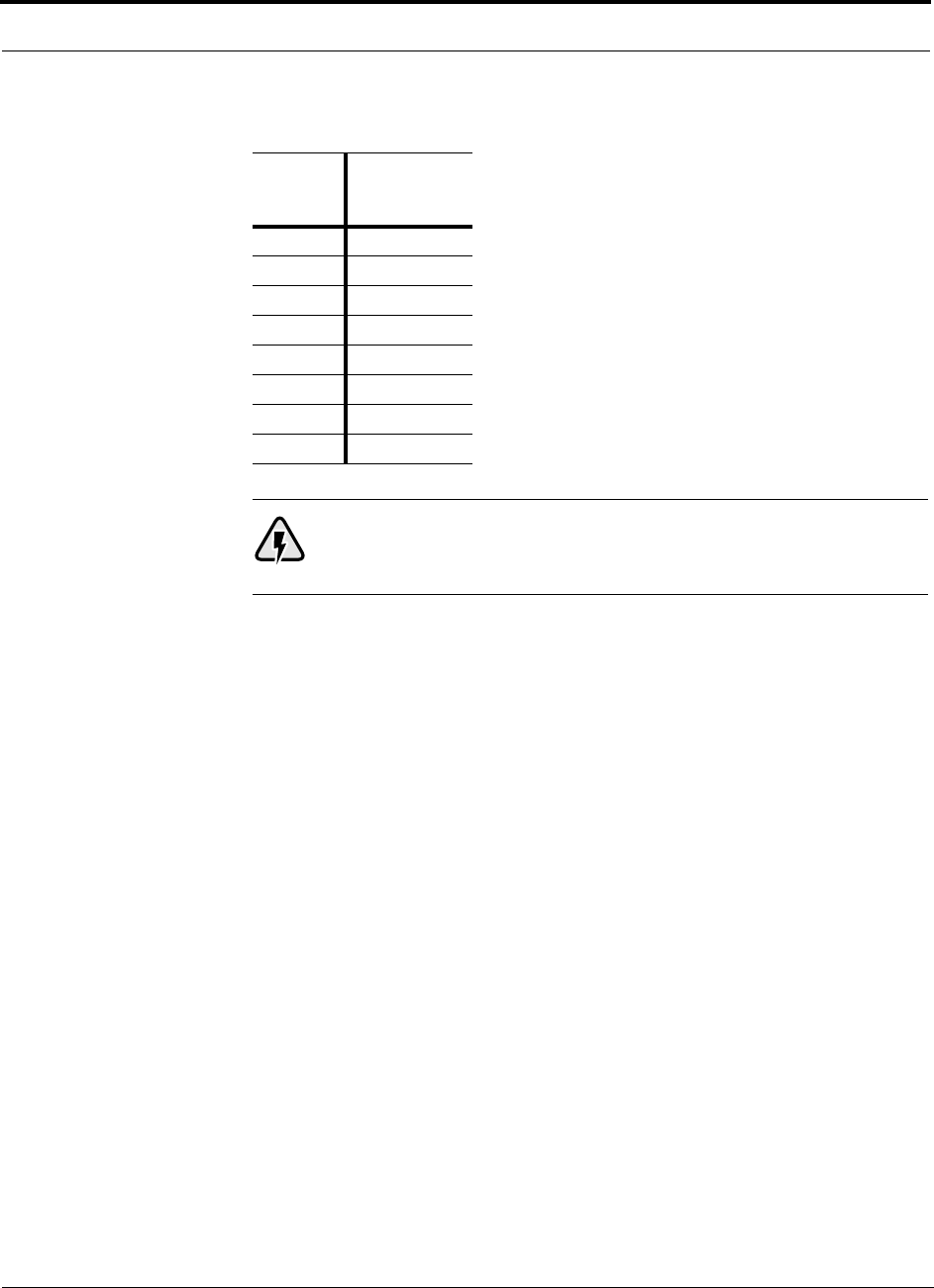
Designing a Unison Solution PRELIMINARY
8-12 InterReach Unison User Guide and Reference Manual PN 8700-10
620003-0
WARNING: For 1800 MHz CDMA (Korea), do not exceed the maxi-
mum composite input power of 1W (+30 dBm) to the Main Hub at any
time.
Table 8-9 1800 MHz (CDMA Korea) Power per Carrier
No. of
Carriers
Power per
Carrier
(dBm)
114.5
212.0
310.5
49.5
58.5
68.0
77.0
86.5

PN 8700-10 Help Hot Line (U.S. only): 1-800-530-9960 8-13
620003-0
PRELIMINARY Maximum Output Power per Carrier at RAU
WARNING: For 1900 MHz TDMA, do not exceed the maximum com-
posite input power of 1W (+30 dBm) to the Main Hub at any time.
Table 8-10 1900 MHz (TDMA) Power per Carrier
No. of
Carriers
Power per
Carrier
(dBm)
110.0
210.0
310.0
410.0
510.0
69.0
78.0
87.0
96.5
10 6.0
11 5.5
12 5.0
13 5.0
14 4.5
15 4.0
16 4.0
20 3.0
30 1.0

Designing a Unison Solution PRELIMINARY
8-14 InterReach Unison User Guide and Reference Manual PN 8700-10
620003-0
WARNING: For 1900 MHz GSM, do not exceed the maximum compos-
ite input power of 1W (+30 dBm) to the Main Hub at any time.
Table 8-11 1900 MHz (GSM) Power per Carrier
No. of
Carriers
Power per
Carrier
(dBm)
110.0
210.0
310.0
410.0
510.0
69.5
78.5
87.5
97.0
10 6.5
11 6.0
12 5.5
13 5.0
14 5.0
15 4.5
16 4.0

PN 8700-10 Help Hot Line (U.S. only): 1-800-530-9960 8-15
620003-0
PRELIMINARY Maximum Output Power per Carrier at RAU
WARNING: For 1900 MHz CDMA, do not exceed the maximum com-
posite input power of 1W (+30 dBm) to the Main Hub at any time.
Table 8-12 1900 MHz (CDMA) Power per Carrier
No. of
Carriers
Power per
Carrier
(dBm)
114.5
212.0
310.5
49.5
58.5
68.0
77.0
86.5

Designing a Unison Solution PRELIMINARY
8-16 InterReach Unison User Guide and Reference Manual PN 8700-10
620003-0
WARNING: For 1900 MHz EDGE, do not exceed the maximum com-
posite input power of 1W (+30 dBm) to the Main Hub at any time.
Table 8-13 1900 MHz (EDGE) Power per Carrier
No. of
Carriers
Power per
Carrier
(dBm)
110.0
210.0
310.0
410.0
59.0
68.0
77.5
86.5
96.0
10 5.5
11 5.0
12 4.5
13 4.5
14 4.0
15 3.5
16 3.5
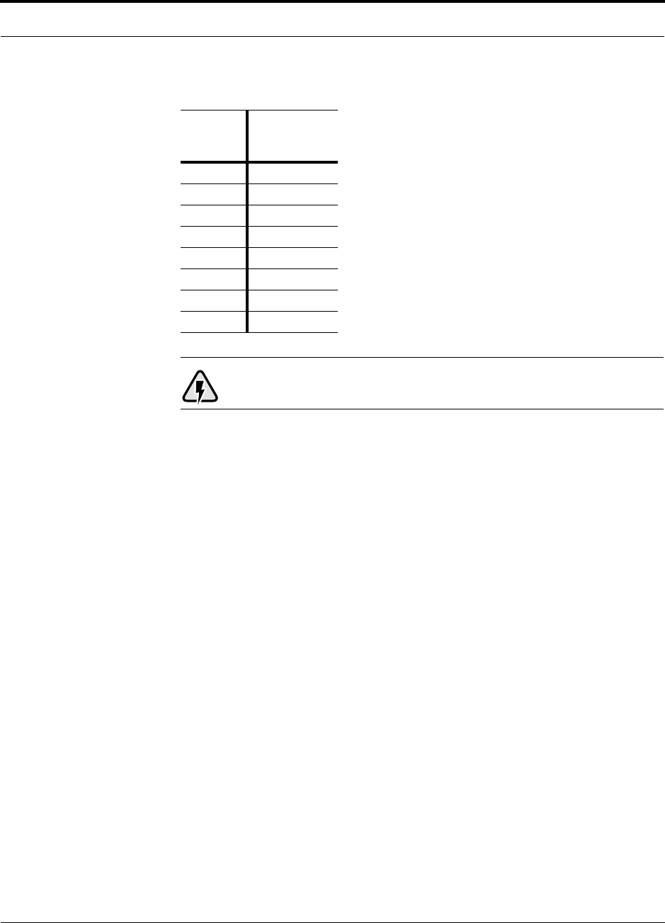
PN 8700-10 Help Hot Line (U.S. only): 1-800-530-9960 8-17
620003-0
PRELIMINARY Maximum Output Power per Carrier at RAU
WARNING: For 2.1 GHz WCDMA, do not exceed the maximum com-
posite input power of 1W (+30 dBm) to the Main Hub at any time.
Table 8-14 2.1 GHz (WCDMA) Power per Carrier
No. of
Carriers
Power per
Carrier
(dBm)
114.5
211.0
38.5
47.0
56.0
65.0
74.5
83.5

Designing a Unison Solution PRELIMINARY
8-18 InterReach Unison User Guide and Reference Manual PN 8700-10
620003-0
Allowing for Future Capacity Growth
Sometimes a Unison deployment initially is used to enhance coverage. Later that
same system may also need to provide increased capacity. Thus, the initial deploy-
ment might only transmit two carriers but need to transmit four (increase this
number? PS) carriers later. There are two options for dealing with this scenario:
1. Design the initial coverage with a maximum power per carrier for four carriers.
2. Design the initial coverage for two carriers but leave Expansion Hub ports
unused. These ports can be used later if coverage holes are discovered once the
power per carrier is lowered to accommodate the two additional carriers.
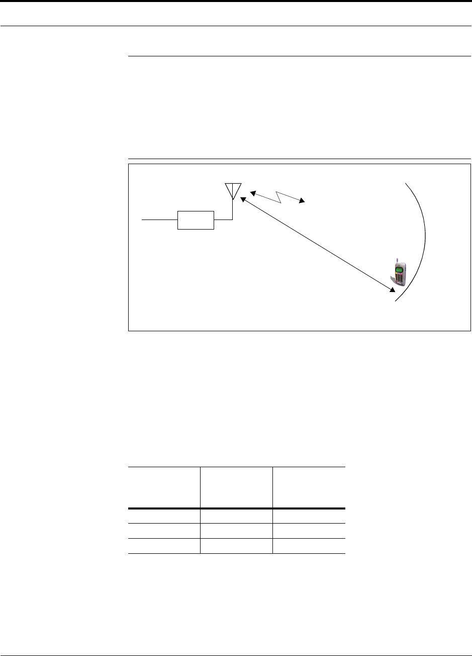
PN 8700-10 Help Hot Line (U.S. only): 1-800-530-9960 8-19
620003-0
PRELIMINARY Estimating RF Coverage
8.2 Estimating RF Coverage
The maximum power per carrier (based on the number and type of RF carriers that
are being transmitted) and the minimum acceptable received power at the wireless
device (i.e., RSSI, the design goal) establish the RF link budget, and consequently the
maximum acceptable path loss between the antenna and the wireless device.
Figure 8-1 Determining Path Loss between the Antenna and the Wireless Device
(P + Lcoax + G) – RSSI = PL (1)
The path loss (PL) is the loss in decibels (dB) between the antenna and the wireless
device. The distance, d, from the antenna corresponding to this path loss can be calcu-
lated using the path loss equations in Section 8.2.1 and in Section 8.2.2.
The following table lists the coaxial cable loss for XXX size cable. Enrique:
What diameter coax? (Adam)
Table 8-15 Coaxial Cable Losses
Length of
Cable
Loss at
800 MHz
(dB)
Loss at
1900 MHz
(dB)
0.9 m (3 ft) 0.4 0.6
1.8 m (6 ft) 0.9 1.4
3.0 m (10 ft) 1.5 2.4
RAU
P = power per d
Antenna and Gain (G)
RSSI = power at the
wireless device
carrier from the RAU

Designing a Unison Solution PRELIMINARY
8-20 InterReach Unison User Guide and Reference Manual PN 8700-10
620003-0
8.2.1 Path Loss Equation
Indoor path loss obeys the distance power law1 in equation (2):
PL = 20log(4πd0f/c) + 10nlog(d/d0) + Χs(2)
where:
• PL is the path loss at a distance, d, from the antenna (the distance between the
antenna that is connected to the RAU and the point where the RF signal
decreases to the minimum acceptable level at the wireless device).
•d
0 is usually taken as 1 meter of free-space.
• f is the operating frequency in hertz.
• c is the speed of light in a vacuum (3.0 × 10⁸ m/sec).
• n is the path loss exponent and depends on the building “clutter”.
•Χs is a normal random variable that depends on partition losses inside the build-
ing, and therefore, depends on the frequency of operation.
As a reference, the following table gives estimates of signal loss for some RF barriers.1
1. Rappaport, Theodore S. Wireless Communications, Principles, and Practice. Prentice Hall PTR, 1996.
Table 8-16 Average Signal Loss of Common Building Materials
Partition Type Loss (dB)
@ <2 GHz Frequency (MHz)
Metal wall 26 815
Aluminum siding 20 815
Foil insulation 4 815
Cubicle walls 1.4 900
Concrete block wall 13 1300
Concrete floor 10 1300
Sheetrock 1 to 2 1300
Light machinery 3 1300
General machinery 7 1300
Heavy machinery 11 1300
Equipment racks 7 1300
Assembly line 6 1300
Ceiling duct 5 1300
Metal stairs 5 1300

PN 8700-10 Help Hot Line (U.S. only): 1-800-530-9960 8-21
620003-0
PRELIMINARY Coverage Distance
8.2.2 Coverage Distance
Equations (1) and (2), on pages 8-19 and 8-20, respectively, can be used to estimate
the distance from the antenna to where the RF signal decreases to the minimum
acceptable level at the wireless device.
Equation (2) can be simplified to:
PL(d) = 20log(4πf/c) + PLSlog(d) (3)
where PLS (path loss slope) is chosen to account for the building’s environment.
Because different frequencies penetrate partitions with different losses, the value of
PLS will vary depending on the frequency.
Table 8-17 shows estimated path loss slope (PLS) for various environments that have
different “clutter” (i.e., objects that attenuate the RF signals, such as walls, partitions,
stairwells, equipment racks, etc.)
For simplicity, Equation (3) can be used to estimate the coverage distance of an
antenna that is connected to an RAU, for a given path loss, frequency, and type of
in-building environment.
Table 8-17 Estimated Path Loss Slope for Different In-Building Environments
Facility PLS for
800/900 MHz PLS for
1800/1900 MHz
Manufacturing 35 32
Hospital 39.4 38.1
Airport 35 32
Retail 36.1 33.1
Warehouse 35 32
Parking Garage 33.7 30.1
Office: 80% cubicle/20% hard wall 36.1 33.1
Office: 50% cubicle/50% hard wall 37.6 34.8
Office: 20% cubicle/80% hard wall 39.4 38.1

Designing a Unison Solution PRELIMINARY
8-22 InterReach Unison User Guide and Reference Manual PN 8700-10
620003-0
Table 8-18 gives the value of the first term of Equation (3) (i.e., (20log(4πf/c)) for
various frequency bands.
Table 8-18 Frequency Bands and the Value of the first Term in Equation (3)
Band (MHz) Mid-Band
Frequency
(MHz) 20log(4πf/c)Uplink Downlink
800 MHz Cellular 824–849 869–894 859 31.1
800 MHz iDEN 806–824 851–869 837.5 30.9
900 MHz GSM 890–915 935–960 925 31.8
900 MHz EGSM 880–915 925–960 920 31.7
1800 MHz DCS 1710–1785 1805–1880 1795 37.5
1800 MHz CDMA (Korea) 1750–1780 1840–1870 1810 37.6
1900 MHz PCS 1850–1910 1930–1990 1920 38.1
2.1 GHz UMTS 1920–1980 2110–2170 2045 TBD

PN 8700-10 Help Hot Line (U.S. only): 1-800-530-9960 8-23
620003-0
PRELIMINARY Coverage Distance
For reference, Tables 8-19 through 8-25 show the distance covered by an antenna for
various in-building environments. The following assumptions were made:
• Path loss Equation (3)
• 6 dBm output per carrier at the RAU output
• 3 dBi antenna gain
• RSSI = –85 dBm (typical for narrowband protocols, but not for spread-spec-
trum protocols)
Table 8-19 Approximate Radiated Distance from Antenna
for 800 MHz Cellular Applications
Facility
Distance from Antenna
Meters Feet
Manufacturing 63 205
Hospital 39 129
Airport 63 205
Retail 55 181
Warehouse 63 205
Parking Garage 73 241
Office: 80% cubicle/20% hard wall 55 181
Office: 50% cubicle/50% hard wall 47 154
Office: 20% cubicle/80% hard wall 39 129
Table 8-20 Approximate Radiated Distance from Antenna
for 800 MHz iDEN Applications
Facility
Distance from Antenna
Meters Feet
Manufacturing 64 208
Hospital 40 131
Airport 64 208
Retail 56 184
Warehouse 64 208
Parking Garage 75 244
Office: 80% cubicle/20% hard wall 56 184
Office: 50% cubicle/50% hard wall 48 156
Office: 20% cubicle/80% hard wall 40 131

Designing a Unison Solution PRELIMINARY
8-24 InterReach Unison User Guide and Reference Manual PN 8700-10
620003-0
Table 8-21 Approximate Radiated Distance from Antenna
for 900 MHz GSM Applications
Facility
Distance from Antenna
Meters Feet
Manufacturing 60 197
Hospital 38 125
Airport 60 197
Retail 53 174
Warehouse 60 197
Parking Garage 70 230
Office: 80% cubicle/20% hard wall 53 174
Office: 50% cubicle/50% hard wall 45 148
Office: 20% cubicle/80% hard wall 38 125
Table 8-22 Approximate Radiated Distance from Antenna
for 900 MHz EGSM Applications
Facility
Distance from Antenna
Meters Feet
Manufacturing 60 197
Hospital 38 125
Airport 60 197
Retail 53 174
Warehouse 60 197
Parking Garage 70 231
Office: 80% cubicle/20% hard wall 53 174
Office: 50% cubicle/50% hard wall 45 149
Office: 20% cubicle/80% hard wall 38 125

PN 8700-10 Help Hot Line (U.S. only): 1-800-530-9960 8-25
620003-0
PRELIMINARY Coverage Distance
Table 8-23 Approximate Radiated Distance from Antenna
for 1800 MHz DCS Applications
Facility
Distance from Antenna
Meters Feet
Manufacturing 58 191
Hospital 30 100
Airport 58 191
Retail 51 167
Warehouse 58 191
Parking Garage 75 246
Office: 80% cubicle/20% hard wall 50 166
Office: 50% cubicle/50% hard wall 42 137
Office: 20% cubicle/80% hard wall 30 100
Table 8-24 Approximate Radiated Distance from Antenna
for 1800 MHz CDMA (Korea) Applications
Facility
Distance from Antenna
Meters Feet
Manufacturing 58 191
Hospital 30 100
Airport 58 191
Retail 51 167
Warehouse 58 191
Parking Garage 75 247
Office: 80% cubicle/20% hard wall 51 167
Office: 50% cubicle/50% hard wall 42 138
Office: 20% cubicle/80% hard wall 30 100

Designing a Unison Solution PRELIMINARY
8-26 InterReach Unison User Guide and Reference Manual PN 8700-10
620003-0
Table 8-25 Approximate Radiated Distance from Antenna
for 1900 MHz PCS Applications
Facility
Distance from Antenna
Meters Feet
Manufacturing 56 183
Hospital 29 96
Airport 56 183
Retail 49 160
Warehouse 56 183
Parking Garage 72 236
Office: 80% cubicle/20% hard wall 49 160
Office: 50% cubicle/50% hard wall 40 132
Office: 20% cubicle/80% hard wall 29 96
Table 8-26 Approximate Radiated Distance from Antenna
for 2.1 GHz UMTS Applications
Facility
Distance from Antenna
Meters Feet
Manufacturing 54 176
Hospital 28 93
Airport 54 176
Retail 47 154
Warehouse 54 176
Parking Garage 69 226
Office: 80% cubicle/20% hard wall 47 154
Office: 50% cubicle/50% hard wall 39 128
Office: 20% cubicle/80% hard wall 28 93

PN 8700-10 Help Hot Line (U.S. only): 1-800-530-9960 8-27
620003-0
PRELIMINARY Examples of Design Estimates
8.2.3 Examples of Design Estimates
Example Design Estimate for an 800 MHz TDMA Application
1. Design goals:
• Cellular (859 MHz = average of the lowest uplink and the highest downlink
frequency in 800 MHz Cellular band)
• TDMA provider
• 6 TDMA carriers in the system
• –85 dBm design goal (to 95% of the building) — the minimum received power
at the wireless device
• Base station with simplex RF connections
2. Power Per Carrier: The tables in Section 8.1, “Maximum Output Power per
Carrier at RAU,” on page 8-3 provide maximum power per carrier information.
The 800 MHz TDMA table (on page 8-5) indicates that Unison can support 6 car-
riers with a recommended maximum power per carrier of 10.5 dBm. The input
power should be set to the desired output power minus the system gain.
3. Building information:
• 8 floor building with 9,290 sq. meters (100,000 sq. ft.) per floor; total 74,322
sq. meters (800,000 sq. ft.)
• Walls are sheetrock construction; suspended ceiling tiles
• Antennas used will be omni-directional, ceiling mounted
• Standard office environment, 50% hard wall offices and 50% cubicles
4. Link Budget: In this example, a design goal of –85 dBm is used. Suppose 3 dBi
omni-directional antennas are used in the design. Then, the maximum RF propa-
gation loss should be no more than 98.5 dB (10.5 dBm + 3 dBi + 85 dBm) over
95% of the area being covered. It is important to note that a design goal such as
–85 dBm is usually derived taking into account multipath fading and log-normal
shadowing characteristics. Thus, this design goal will only be met “on average”
over 95% of the area being covered. At any given point, a fade may bring the sig-
nal level underneath the design goal.
Note that this method of calculating a link budget is only for the downlink path.
For information to calculate link budgets for both the downlink and uplink paths,
see Section 8.4 on page 8-32.
5. Path Loss Slope: For a rough estimate, Table 8-17, “Estimated Path Loss Slope for
Different In-Building Environments” on page 8-21, shows that a building with 50%
hard wall offices and 50% cubicles, at 859 MHz, has an approximate path loss slope
(PLS) of 37.6. Given the RF link budget of 98.5 dB, the distance of coverage from
each RAU will be 60/62 meters (198/203 ft). This corresponds to a coverage
area of 11,465/12,079 sq. meters (123,409/129,952 sq. ft.) per RAU (see
Section 8.2.1 for details on path loss estimation). For this case we assumed a circu-
lar radiation pattern, though the actual area covered will depend upon the pattern of
the antenna and the obstructions in the facility.

Designing a Unison Solution PRELIMINARY
8-28 InterReach Unison User Guide and Reference Manual PN 8700-10
620003-0
Adam and Rich provided different distance numbers. Which are
correct? JW
6. Equipment Required: Since you know the building size, you can now estimate
the Unison equipment quantities that will be needed. Before any RF levels are
tested in the building, you can estimate that 2 antennas per level will be needed.
a. 1 antenna per floor × 8 floors = 8 RAUs
b. 8 RAUs ÷ 8 (max 8 RAUs per Expansion Hub) = 1 Expansion Hubs
c. 1 Expansion Hubs ÷ 4 (max 4 Expansion Hubs per Main Hub) = 1 Main Hub
Check that the MMF and Cat-5 cable distances are as recommended. If the dis-
tances differ, use the tables in Section 8.3, “System Gain,” on page 8-31 to deter-
mine system gains or losses. The path loss may need to be recalculated to assure
adequate signal levels in the required coverage distance.
The above estimates assume that all cable length requirements are met. If Expansion
Hubs cannot be placed so that the RAUs are within the distance requirement, addi-
tional Expansion Hubs may need to be placed closer to the required RAUs locations.
An RF Site Survey and Building Evaluation is required to accurately establish the
Unison equipment quantities required for the building. The site survey measures the
RF losses within the building to determine the actual PLS, which will be used in the
final path loss formula to determine the actual requirements of the Unison system.

PN 8700-10 Help Hot Line (U.S. only): 1-800-530-9960 8-29
620003-0
PRELIMINARY Examples of Design Estimates
Example Design Estimate for an 1900 MHz CDMA Application
1. Design goals:
• PCS (1920 MHz = average of the lowest uplink and the highest downlink fre-
quency in 1900 MHz PCS band)
• CDMA provider
• 8 CDMA carriers in the system
• –85 dBm design goal (to 95% of the building) — the minimum received power
at the wireless device
• Base station with simplex RF connections
2. Power Per Carrier: The tables in Section 8.1, “Maximum Output Power per
Carrier at RAU,” on page 8-3 provide maximum power per carrier information.
The 1900 MHz CDMA table (on page 8-15) indicates that Unison can support 8
carriers with a recommended maximum power per carrier of 6.5 dBm. The input
power should be set to the desired output power minus the system gain.
3. Building information:
• 16 floor building with 9,290 sq. meters (100,000 sq. ft.) per floor; total
148,640 sq. meters (1,600,000 sq. ft.)
• Walls are sheetrock construction; suspended ceiling tiles
• Antennas used will be omni-directional, ceiling mounted
• Standard office environment, 80% hard wall offices and 20% cubicles
4. Link Budget: In this example, a design goal of –85 dBm is used. Suppose 3 dBi
omni-directional antennas are used in the design. Then, the maximum RF propa-
gation loss should be no more than 94.5 dB (6.5 dBm + 3 dBi + 85 dBm) over
95% of the area being covered. It is important to note that a design goal such as
–85 dBm is usually derived taking into account multipath fading and log-normal
shadowing characteristics. Thus, this design goal will only be met “on average”
over 95% of the area being covered. At any given point, a fade may bring the sig-
nal level underneath the design goal.
Note that this method of calculating a link budget is only for the downlink path.
For information to calculate link budgets for both the downlink and uplink paths,
see Section 8.4 on page 8-32.
5. Path Loss Slope: For a rough estimate, Table 8-17, “Estimated Path Loss Slope for
Different In-Building Environments” on page 8-21, shows that a building with 80%
hard wall offices and 20% cubicles, at 1920 MHz, has an approximate path loss
slope (PLS) of 38.1. Given the RF link budget of 94.5 dB, the distance of coverage
from each RAU will be 50 meters (166 ft). This corresponds to a coverage area of
8,031 sq. meters (86,404 sq. ft.) per RAU (see Section 8.2.1 for details on path loss
estimation). For this case we assumed a circular radiation pattern, though the actual
area covered will depend upon the pattern of the antenna and the obstructions in the
facility.

Designing a Unison Solution PRELIMINARY
8-30 InterReach Unison User Guide and Reference Manual PN 8700-10
620003-0
6. Equipment Required: Since you know the building size, you can now estimate
the Unison equipment quantities that will be needed. Before any RF levels are
tested in the building, you can estimate that 2 antennas per level will be needed.
a. 2 antennas per floor × 16 floors = 32 RAUs
b. 32 RAUs ÷ 8 (max 8 RAUs per Expansion Hub) = 4 Expansion Hubs
c. 4 Expansion Hubs ÷ 4 (max 4 Expansion Hubs per Main Hub) = 1 Main Hub
Check that the MMF and Cat-5 cable distances are as recommended. If the dis-
tances differ, use the tables in Section 8.3, “System Gain,” on page 8-31 to deter-
mine system gains or losses. The path loss may need to be recalculated to assure
adequate signal levels in the required coverage distance.
The above estimates assume that all cable length requirements are met. If Expansion
Hubs cannot be placed so that the RAUs are within the distance requirement, addi-
tional Expansion Hubs may need to be placed closer to the required RAUs locations.
An RF Site Survey and Building Evaluation is required to accurately establish the
Unison equipment quantities required for the building. The site survey measures the
RF losses within the building to determine the actual PLS, which will be used in the
final path loss formula to determine the actual requirements of the Unison system.

PN 8700-10 Help Hot Line (U.S. only): 1-800-530-9960 8-31
620003-0
PRELIMINARY System Gain
8.3 System Gain
The system gain can be decreased from 15 dB to 0 dB gain in 1 dB increments and
the uplink and downlink gain of any RAU can be decreased by 10 dB in one step
using AdminManager or OpsConsole.
8.3.1 System Gain (Loss) Relative to ScTP Cable Length
The recommended minimum length of ScTP cable is 20 meters (66 ft) and the recom-
mended maximum length is 100 meters (328 ft). If the ScTP cable is less than 10
meters (33 ft), system performance may not meet specifications. If the ScTP cable is
longer than 100 meters (328 ft), the gain of the system will decrease, as shown in
Table 8-27.
I need 2.1 GHz figures for this table. JW
Table 8-27 System Gain (Loss) Relative to ScTP Cable Length
ScTP Cable
Length
Typical change in system gain (dB)
Downlink Uplink
800 MHz TDMA/AMPS and CDMA; 900 MHz GSM and
EGSM; and iDEN
110 m / 361 ft –1.0 –0.7
120 m / 394 ft –3.2 –2.4
130 m / 426 ft –5.3 –4.1
140 m / 459 ft –7.5 –5.8
150 m / 492 ft –9.7 7.6
1800 MHz GSM (DCS); 1900 MHz TDMA, CDMA, and GSM
110 m / 361 ft –1.0 –0.7
120 m / 394 ft –4.0 –2.4
130 m / 426 ft –6.4 –4.1
140 m / 459 ft –8.8 –5.8
150 m / 492 ft –11.3 –7.6
2.1 GHz UMTS
110 m / 361 ft
120 m / 394 ft
130 m / 426 ft
140 m / 459 ft
150 m / 492 ft

Designing a Unison Solution PRELIMINARY
8-32 InterReach Unison User Guide and Reference Manual PN 8700-10
620003-0
8.4 Link Budget Analysis
A link budget is a methodical way to account for the gains and losses in an RF system
so that the quality of coverage can be predicted. The end result can often be stated as
a “design goal” in which the coverage is determined by the maximum distance from
each RAU before the signal strength falls beneath that goal.
One key feature of the link budget is the maximum power per carrier discussed in
Section 8.1. While the maximum power per carrier is important as far as emissions
and signal quality requirements are concerned, it is critical that the maximum signal
into the Main Hub never exceed 1W (+30 dBm). Composite power levels above this
limit will cause damage to the Main Hub.
WARNING: Exceeding the maximum input power of 1W (+30 dBm)
could cause permanent damage to the Main Hub.

PN 8700-10 Help Hot Line (U.S. only): 1-800-530-9960 8-33
620003-0
PRELIMINARY Elements of a Link Budget for Narrowband Standards
8.4.1 Elements of a Link Budget for Narrowband Standards
The link budget represents a typical calculation that might be used to determine how
much path loss can be afforded in a Unison design. This link budget analyzes both the
downlink and uplink paths. For most configurations, the downlink requires lower
path loss and is therefore the limiting factor in the system design. It is for this reason
that a predetermined “design goal” for the downlink is sufficient to predict coverage
distance.
The link budget is organized in a simple manner: the transmitted power is calculated,
the airlink losses due to fading and body loss are summed, and the receiver sensitivity
(minimum level a signal can be received for acceptable call quality) is calculated. The
maximum allowable path loss (in dB) is the difference between the transmitted
power, less the airlink losses, and the receiver sensitivity. From the path loss, the
maximum coverage distance can be estimated using the path loss formula presented
in Section 8.2.1.
Table 8-28 provides link budget considerations for narrowband systems.
Table 8-28 Link Budget Considerations for Narrowband Systems
Consideration Description
BTS Transmit Power The power per carrier transmitted from the base station output
Attenuation between
BTS and Unison
This includes all losses: cable, attenuator, splitter/combiner, and so forth.
On the downlink, attenuation must be chosen so that the maximum power per carrier going into the
Main Hub does not exceed the levels given in Section 8.1.
On the uplink, attenuation is chosen to keep the maximum uplink signal and noise level low enough
to prevent base station alarms but small enough not to cause degradation in the system sensitivity.
If the Unison noise figure minus the attenuation is at least 10 dB higher than the BTS noise figure,
the system noise figure will be approximately that of Unison alone. See Section 8.6 for ways to inde-
pendently set the uplink and downlink attenuations between the base station and Unison.
Unison Gain This is the system gain (see Table 8-26 on page 8-29)
Antenna Gain The radiated output power includes antenna gain. For example, if you use a 3 dBi antenna at the
RAU that is transmitting 0 dBm per carrier, the effective radiated power (relative to an isotropic
radiator) is 3 dBm per carrier.
BTS Noise Figure This is the effective noise floor of the base station input (usually base station sensitivity is this effec-
tive noise floor plus a certain C/I ratio).
Unison Noise Figure This is Unison’s uplink noise figure, which varies depending on the number of Expansion Hubs and
RAUs, and the frequency band. Unison’s uplink noise figure is specified for a 1-1-4 configuration.
Thus, the noise figure for a Unison system (or multiple systems whose uplink ports are power com-
bined) will be NF(1-1-4) + 10*log(# of Expansion Hubs). This represents an upper-bound because
the noise figure is lower if any of the Expansion Hub’s RAU ports are not used.

Designing a Unison Solution PRELIMINARY
8-34 InterReach Unison User Guide and Reference Manual PN 8700-10
620003-0
Thermal Noise This is the noise level in the signal bandwidth (BW).
Thermal noise power = –174 dBm/Hz + 10Log(BW).
Required C/I ratio For each wireless standard a certain C/I (carrier to interference) ratio is needed to obtain acceptable
demodulation performance. For narrowband systems, (TDMA, GSM, EDGE, iDEN, AMPS) this
level varies from about 9 dB to 20 dB.
Mobile Transmit
Power
The maximum power the mobile can transmit (power transmitted at highest power level setting).
Multipath Fade
Margin
This margin allows for a certain level of fading due to multipath interference. Inside buildings there
is often one or more fairly strong signals and many weaker signals arriving from reflections and dif-
fraction. Signals arriving from multiple paths add constructively or destructively. This margin
accounts for the possibility of destructive multipath interference. In RF site surveys this margin will
not appear because it will be averaged out over power level samples taken over many locations.
Log-normal Fade
Margin
This margin adds an allowance for RF shadowing due to objects obstructing the direct path between
the mobile equipment and the RAU. In RF site surveys, this shadowing will not appear because it
will be averaged out over power level samples taken over many locations.
Body Loss This accounts for RF attenuation caused by the user’s head and body.
Minimum Received
Signal Level
This is also referred to as the “design goal”. The link budget says that you can achieve adequate cov-
erage if the signal level is, on average, above this level over 95% of the area covered, for example.
Table 8-28 Link Budget Considerations for Narrowband Systems (continued)
Consideration Description
Protocol Signal
Bandwidth Thermal
Noise
TDMA 30 kHz –129 dBm
CDMA 1.25 MHz –113 dBm spread-spectrum, remove?
PS
GSM 200 kHz –121 dBm
iDEN 25 kHz –130 dBm

PN 8700-10 Help Hot Line (U.S. only): 1-800-530-9960 8-35
620003-0
PRELIMINARY Narrowband Link Budget Analysis for a Microcell Application
8.4.2 Narrowband Link Budget Analysis for a Microcell Application
Narrowband Link Budget Analysis: Downlink
• c = a + b
• f = c + d + e
• j = g + h + i
• n = k + l + m
• k: in this example, k represents the thermal noise for a TDMA signal, which
has a bandwidth of 30 kHz
•p = f – j – n
Line Downlink
Transmitter
a. BTS transmit power per carrier (dBm) 33
b. Attenuation between BTS and Unison (dB) –23
c. Power into Unison (dBm) 10
d. Unison gain (dB) 0
e. Antenna gain (dBi) 3
f. Radiated power per carrier (dBm) 13
Airlink
g. Multipath fade margin (dB) 6
h. Log-normal fade margin with 8 dB std. deviation, edge reliability 90%
(dB)
10
i. Body loss (dB) 3
j. Airlink losses (not including facility path loss) 19
Receiver
k. Thermal noise (dBm/30 kHz) –129
l. Mobile noise figure (dB) 7
m. Required C/I ratio (dB) 12
n. Minimum received signal (dBm) –110
p. Maximum path loss (dB) 104
Adam,
Any WCDMA issues?
(PS)

Designing a Unison Solution PRELIMINARY
8-36 InterReach Unison User Guide and Reference Manual PN 8700-10
620003-0
Narrowband Link Budget Analysis: Uplink
• e: enter the noise figure and gain of each system component (a, b, c, and d) into
the standard cascaded noise figure formula
• i = f + e + g – h
• m = j + k + l
• p = n – m – i
Line Uplink
Receiver
a. BTS noise figure (dB) 4
b. Attenuation between BTS and Unison (dB) –10
c. Unison gain (dB) 0
d. Unison noise figure (dB) 1-4-32 22
e. System noise figure (dB) 22.6
f. Thermal noise (dBm/30 kHz) –129
g. Required C/I ratio (dB) 12
h. Antenna gain (dBi) 3
i. Receive sensitivity (dBm) –97.4
Airlink
j. Multipath fade margin (dB) 6
k. Log-normal fade margin with 8 dB std. deviation, edge reliability 90%
(dB)
10
l. Body loss (dB) 3
m. Airlink losses (not including facility path loss) 19
Transmitter
n. Mobile transmit power (dBm) 28
p. Maximum path loss (dB) 106.4
Fsys = F1 + + + ....
F2 – 1
G1
F3 – 1
G1G2
where
F = 10
(See Rappaport, Theodore S. Wireless Communications, Principles, and Practice. Prentice Hall PTR, 1996.)
(Noise Figure/10)
G = 10(Gain/10)

PN 8700-10 Help Hot Line (U.S. only): 1-800-530-9960 8-37
620003-0
PRELIMINARY Elements of a Link Budget for CDMA Standards
8.4.3 Elements of a Link Budget for CDMA Standards
A CDMA link budget is slightly more complicated because the spread spectrum
nature of CDMA must be considered. Unlike narrowband standards such as TDMA
and GSM, CDMA signals are spread over a relatively wide frequency band. Upon
reception, the CDMA signal is de-spread. In the de-spreading process the power in
the received signal becomes concentrated into a narrow band, whereas the noise level
remains unchanged. Hence, the signal-to-noise ratio of the de-spread signal is higher
than that of the CDMA signal before de-spreading. This increase is called processing
gain. For IS-95 and J-STD-008, the processing gain is 21 dB or 19 dB depending on
the user data rate (9.6 Kbps for rate set 1 and 14.4 Kbps for rate set 2, respectively).
Because of the processing gain, a CDMA signal (comprising one Walsh code channel
within the composite CDMA signal) can be received at a lower level than that
required for narrowband signals. A reasonable level is –95 dBm, which results in
about –85 dBm composite as shown below.
An important issue to keep in mind is that the downlink CDMA signal is composed of
many orthogonal channels: pilot, paging, sync, and traffic. The composite power
level is the sum of the powers from the individual channels. An example is given in
the following table.
This table assumes that there are 15 active traffic channels operating with 50% voice
activity (so that the total power adds up to 100%). Notice that the pilot and sync chan-
nels together contribute about 25% of the power. When measuring the power in a
CDMA signal you must be aware that if only the pilot and sync channels are active,
the power level will be about 6 to 7 dB lower than the maximum power level you can
expect when all voice channels are active. The implication is that if only the pilot and
sync channels are active, and the maximum power per carrier table says that you
should not exceed 10 dBm for a CDMA signal, for example, then you should set the
attenuation between the base station and the Main Hub so that the Main Hub receives
3 dBm (assuming 0 dB system gain).
An additional consideration for CDMA systems is that the uplink and downlink paths
should be gain and noise balanced. This is required for proper operation of soft-hand-
off to the outdoor network as well as preventing excess interference that is caused by
mobiles on the indoor system transmitting at power levels that are not coordinated
with the outdoor mobiles. This balance is achieved if the power level transmitted by
the mobiles under close-loop power control is similar to the power level transmitted
under open-loop power control. The open-loop power control equation is
PTX + PRX = –73 dBm (for Cellular, IS-95)
Table 8-29 Distribution of Power within a CDMA Signal
Channel Walsh Code Number Relative Power Level
Pilot 0 20% –7.0 dB
Sync 32 5% –13.3 dB
Primary Paging 1 19% –7.3 dB
Traffic 8–31, 33–63 9% (per traffic channel) –10.3 dB

Designing a Unison Solution PRELIMINARY
8-38 InterReach Unison User Guide and Reference Manual PN 8700-10
620003-0
PTX + PRX = –76 dBm (for PCS, J-STD-008)
where PTX is the mobile’s transmitted power and PRX is the power received by the
mobile.
The power level transmitted under closed-loop power control is adjusted by the base
station to achieve a certain Eb/N0 (explained in Table 8-30 on page 8-38). The differ-
ence between these power levels, ∆P, can be estimated by comparing the power radi-
ated from the RAU, Pdownink, to the minimum received signal, Puplink, at the RAU:
∆P = Pdownink + Puplink + 73 dBm (for Cellular)
∆P = Pdownink + Puplink + 76 dBm (for PCS)
It’s a good idea to keep –12 dB < ∆P < 12 dB.
Table 8-30 provides link budget considerations for CDMA systems.
Table 8-30 Additional Link Budget Considerations for CDMA Systems
Consideration Description
Multipath Fade
Margin
The multipath fade margin can be reduced (by at least 3 dB) by using different lengths of optical fiber (this
is called “delay diversity”). The delay over fiber is approximately 5µS/km. If the difference in fiber
lengths to Expansion Hubs with overlapping coverage areas produces at least 1 chip (0.8µS) delay of one
path relative to the other, then the multipaths’ signals can be resolved and processed independently by the
base station’s rake receiver. A CDMA signal traveling through 163 meters of MMF cable will be delayed
by approximately one chip.
Power per car-
rier, downlink
This depends on how many channels are active. For example, the signal will be about 7 dB lower if only
the pilot, sync, and paging channels are active compared to a fully-loaded CDMA signal. Furthermore, in
the CDMA forward link, voice channels are turned off when the user is not speaking. On average this is
assumed to be about 50% of the time. So, in the spreadsheet, both the power per Walsh code channel (rep-
resenting how much signal a mobile will receive on the Walsh code that it is de-spreading) and the total
power are used.
The channel power is needed to determine the maximum path loss, and the total power is needed to deter-
mine how hard the Unison system is being driven.
The total power for a fully-loaded CDMA signal is given by (approximately):
total power = voice channel power + 13 dB + 10log10 (50%)
= voice channel power + 10 dB
Information Rate This is simply
10log10(9.6 Kbps) = 40 dB for rate set 1
10log10(14.4 Kbps) = 42 dB for rate set 2
Process Gain The process of de-spreading the desired signal boosts that signal relative to the noise and interference.
This gain needs to be included in the link budget. In the following formulas, PG = process gain:
PG = 10log10(1.25 MHz / 9.6 Kbps) = 21 dB rate set 1
PG = 10log10(1.25 MHz / 14.4 Kbps) = 19 dB rate set 2
Note that the process gain can also be expressed as 10log10 (CDMA bandwidth) minus the information
rate.

PN 8700-10 Help Hot Line (U.S. only): 1-800-530-9960 8-39
620003-0
PRELIMINARY Elements of a Link Budget for CDMA Standards
Other CDMA Issues
• Never combine multiple sectors (more than one CDMA signal at the same fre-
quency) into a Unison system. The combined CDMA signals will interfere with
each other.
• Try to minimize overlap between in-building coverage areas that utilize different
sectors, as well as in-building coverage and outdoor coverage areas. This is impor-
tant because any area in which more than one dominant pilot signal (at the same
frequency) is measured by the mobile will result in soft-handoff. Soft-handoff
decreases the overall network capacity by allocating multiple channel resources to
a single mobile phone.
Eb/No This is the energy-per-bit divided by the received noise and interference. It’s the CDMA equivalent of sig-
nal-to-noise ratio (SNR). This figure depends on the mobile’s receiver and the multipath environment. For
example, the multipath delays inside a building are usually too small for a rake receiver in the mobile (or
base station) to resolve and coherently combine multipath components. However, if artificial delay can be
introduced by, for instance, using different lengths of cable, then the required Eb/No will be lower and the
multipath fade margin in the link budget can be reduced in some cases.
If the receiver noise figure is NF (dB), then the receive sensitivity (dBm) is given by:
Psensitivity = NF + Eb/No + thermal noise in a 1.25 MHz band – PG
= NF + Eb/No – 113 (dBm/1.25 MHz) – PG
Noise Rise On the uplink, the noise floor is determined not only by the Unison system, but also by the number of
mobiles that are transmitting. This is because when the base station attempts to de-spread a particular
mobile’s signal, all other mobile signals appear to be noise. Because the noise floor rises as more mobiles
try to communicate with a base station, the more mobiles there are, the more power they have to transmit.
Hence, the noise floor rises rapidly:
noise rise = 10log10(1 / (1 – loading))
where loading is the number of users as a percentage of the theoretical maximum number of users.
Typically, a base station is set to limit the loading to 75%. This noise ratio must be included in the link
budget as a worst-case condition for uplink sensitivity. If there are less users than 75% of the maximum,
then the uplink coverage will be better than predicted.
Hand-off Gain CDMA supports soft hand-off, a process by which the mobile communicates simultaneously with more
than one base station or more than one sector of a base station. Soft hand-off provides improved receive
sensitivity because there are two or more receivers or transmitters involved. A line for hand-off gain is
included in the CDMA link budgets worksheet although the gain is set to 0 dB because the in-building
system will probably be designed to limit soft-handoff.
Table 8-30 Additional Link Budget Considerations for CDMA Systems
Consideration Description

Designing a Unison Solution PRELIMINARY
8-40 InterReach Unison User Guide and Reference Manual PN 8700-10
620003-0
8.4.4 Spread Spectrum Link Budget Analysis for a Microcell
Application
Spread Spectrum Link Budget Analysis: Downlink
Line Downlink
Transmitter
a. BTS transmit power per traffic channel (dBm) 30.0
b. Voice activity factor 50%
c. Composite power (dBm) 40.0
d. Attenuation between BTS and Unison (dB) –24
e. Power per channel into Unison (dBm) 9.0
f. Composite power into Unison (dBm) 16.0
g. Unison gain (dB) 0.0
h. Antenna gain (dBi) 3.0
i. Radiated power per channel (dBm) 12.0
j. Composite radiated power (dBm) 19.0
Airlink
k. Handoff gain (dB) 0.0
l. Multipath fade margin (dB) 6.0
m. Log-normal fade margin with 8 dB std. deviation, edge reliability
90% (dB)
10.0
n. Additional loss (dB) 0.0
o. Body loss (dB) 3.0
p. Airlink losses (not including facility path loss) 19.0
Receiver
q. Mobile noise figure (dB) 7.0
r. Thermal noise (dBm/Hz) –174.0
s. Receiver interference density (dBm/Hz) –167.0
t. Information ratio (dB/Hz) 41.6
u. Required Eb/(No+lo)7.0
v. Receive Sensitivity (dBm) –118.4
w. Minimum received signal (dBm) –99.4
x. Maximum path loss (dB) –99.4
y. Difference between open- and closed-loop transmitter power (dB) –2.0
Adam, you said to move
“y” to the next page, but
didn’t tell me where to move it to. Julie

PN 8700-10 Help Hot Line (U.S. only): 1-800-530-9960 8-41
620003-0
PRELIMINARY Spread Spectrum Link Budget Analysis for a Microcell Application
• b and c: see notes in Table 8-30 regarding power per carrier, downlink
• e = a + d
•f = c + d
• i = e + g + h
• j = f + g + h
• p = –k + l + m + n + o
• s = q + r
• v = s + t + u
• w = p + v
•x = j – w
• y = j (downlink) + m (uplink) + P
where
P = Ptx + Prx = –73 dB for Cellular
–76 dB for PCS

Designing a Unison Solution PRELIMINARY
8-42 InterReach Unison User Guide and Reference Manual PN 8700-10
620003-0
Spread Spectrum Link Budget Analysis: Uplink
Line Uplink
Receiver
a. BTS noise figure (dB) 3.0
b. Attenuation between BTS and Unison (dB) –30.0
c. Unison gain (dB) 0.0
d. Unison noise figure (dB) 22.0
e. System noise figure (dB) 33.3
f. Thermal noise (dBm/Hz) –174.0
g. Noise rise 75% loading (dB) 6.0
h. Receiver interference density (dBm/Hz) –134.6
i. Information rate (dB/Hz) 41.6
j. Required Eb/(No+lo)5.0
k. Handoff gain (dB) 0.0
l. Antenna gain (dBi) 3.0
m. Minimum received signal (dBm) –91.1
Airlink
n. Multipath fade margin (dB) 6.0
o. Log-normal fade margin with 8 dB std. deviation, edge reliability
90% (dB)
10.0
p. Additional loss (dB) 0.0
q. Body loss (dB) 3.0
r. Airlink losses (not including facility path loss) 19.0
Transmitter
s. Mobile transmit power (dBm) 28.0
t. Maximum path loss (dB) 100.1

PN 8700-10 Help Hot Line (U.S. only): 1-800-530-9960 8-43
620003-0
PRELIMINARY Spread Spectrum Link Budget Analysis for a Microcell Application
• e: enter the noise figure and gain of each system component (a, b, c, and d) into
the standard cascaded noise figure formula
• h = e + f + g
• m = h + i + j –k – l
• r = n + o + p + q
• t = s – r – m
Fsys = F1 + + + ....
F2 – 1
G1
F3 – 1
G1G2
where
F = 10
(See Rappaport, Theodore S. Wireless Communications, Principles, and Practice. Prentice Hall PTR, 1996.)
(Noise Figure/10)
G = 10(Gain/10)

Designing a Unison Solution PRELIMINARY
8-44 InterReach Unison User Guide and Reference Manual PN 8700-10
620003-0
8.4.5 Considerations for Re-Radiation (over-the-air) Systems
The Unison can be used to extend the coverage of the outdoor network by connecting
to a roof-top donor antenna that is pointed toward an outdoor base station. Additional
considerations for such an application of the Unison are:
• Sizing the gain and output power requirements for a bi-directional amplifier
(repeater).
• Ensuring that noise radiated on the uplink from the in-building system does not
cause the outdoor base station to become desensitized to wireless handsets in the
outdoor network.
• Filtering out signals that lie in adjacent frequency bands. For instance, if you are
providing coverage for Cellular B-band operation it may be necessary to filter out
the A, A’ and A” bands which may contain strong signals from other outdoor base
stations.
Further information on these issues can be found in LGC Wireless’ application notes
for re-radiation applications.
Rich, are we supporting re-rad applications? (PS)
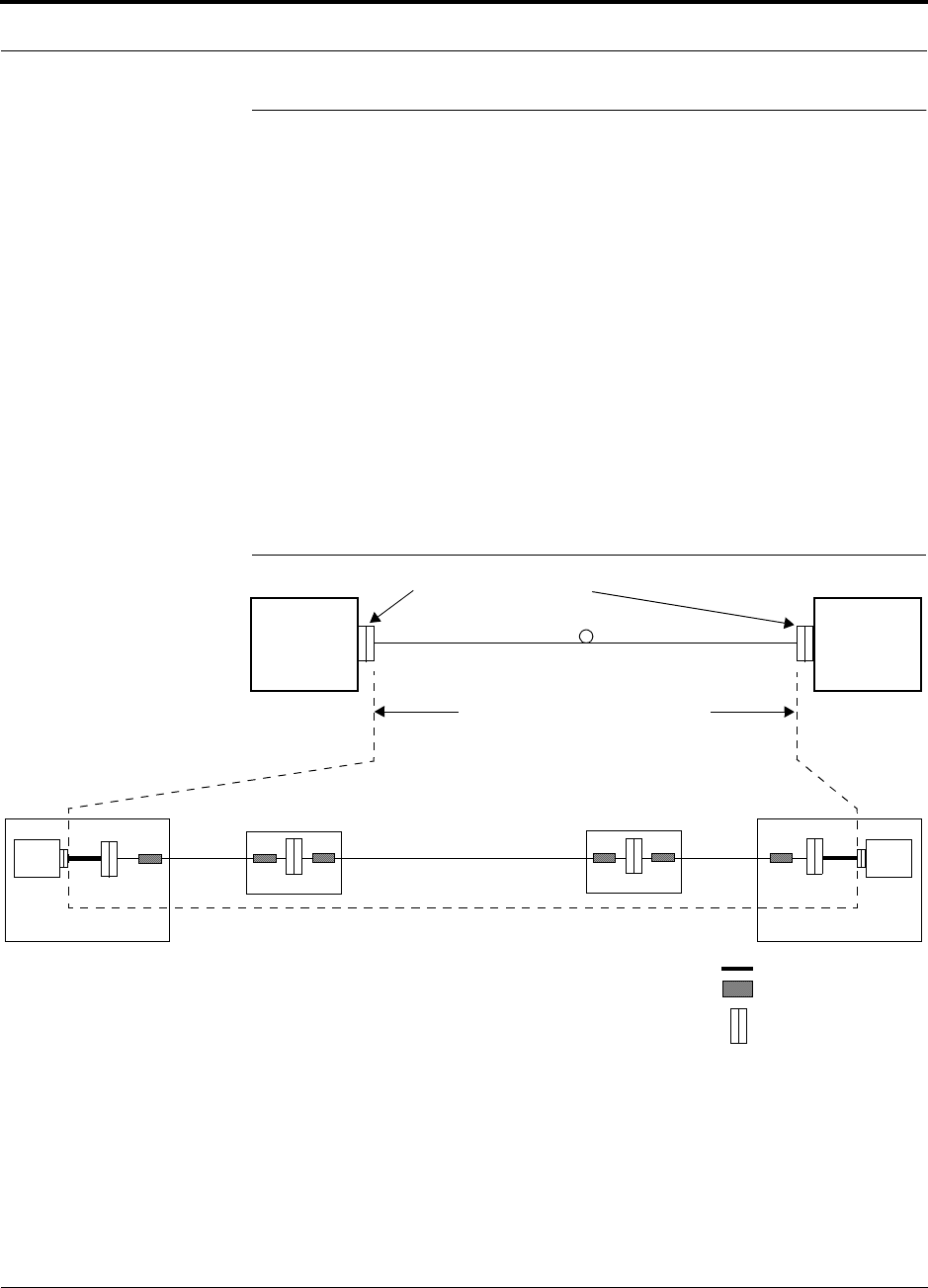
PN 8700-10 Help Hot Line (U.S. only): 1-800-530-9960 8-45
620003-0
PRELIMINARY Optical Power Budget
8.5 Optical Power Budget
Rich is updating this section for Unison.
Unison uses SC/APC connectors. The connector losses associated with mating to
these connectors is accounted for in the design and should not be included as ele-
ments of the Optical Power Budget. The reason is that when the Optical Power Bud-
get is defined, measurements are taken with these connectors in place.
The Main Hub/Expansion Hub link uses one fiber strand and its
Optical Power Budget is:
• Uplink: 5.5 dB @ 1550 nm
• Downlink: 7 dB @ 1310 nm
The following figure shows what is to be included when calculating Optical Power
Budget losses.
Figure 1 Losses to be Included in Optical Power Budget
Main
Hub Expansion
Hub
Mated SC/APC Connectors
To be included in Optical Power Budget
MH EH
Equipment Room
OSP POE
Equipment Room
ISP Cable ISP CableOSP Cable
SMF Jumper
FDP SC/APC Bulk Head
Fusion Splice
OSP POE
OSP = Outside Plant
ISP = Inside Plant
POE = Point of Entry

Designing a Unison Solution PRELIMINARY
8-46 InterReach Unison User Guide and Reference Manual PN 8700-10
620003-0
The following table lists the typical losses from the configuration shown in Figure 1.
NOTE: Where known losses are less than 1.7 dB (1310 or 1550), the potential reach
will exceed 15 km. For CDMA, care must be taken to ensure that the fiber-induced
latencies do not conflict with the Operator’s PN offset plan.
Description Downlink
(1310 nm) Loss
Subtotal Uplink
(1550 nm) Loss
Subtotal Source
Optical Power Budget (dB) 7 5.5 LGC Wireless
Inside Plant Cable Loss (dB/km) 0.5 0.5 OCC/
CommScope
Cable Length (km)a
a. This length will vary for each individual building.
1.2 0.6 1.2 0.6
SMF Jumper Loss (approx. dB/km)b
b. It is assumed that the SMF jumpers are less than a meter and therefore their loss is negligible.
1.0 0.0 0.5 0.0
SC/APC Insertion Loss (dB): 4 used 0.25 1.0 0.25 1.0 Siecor
Fusion Splice Loss (dB): 6 used 0.05 0.3 0.05 0.3 Alcoa Fujikura
Losses (dB) 1.9 1.9
Available budget for OSP (dB)
(Optical Power Budget – Known Losses) 5.1 3.6
Outside Plant Cable Loss (dB/km) 0.35 0.25 CommScope
Optical Power Budget
– Known Losses
÷ Outside Plant Cable Loss
= Potential Fiber Length (km)c
c. Actual fiber length may vary due to the quantity and quality of fiber splices in the OSP network.
7
– 5.1
÷ 0.35
14.57
5.5
– 3.6
÷ 0.25
14.40
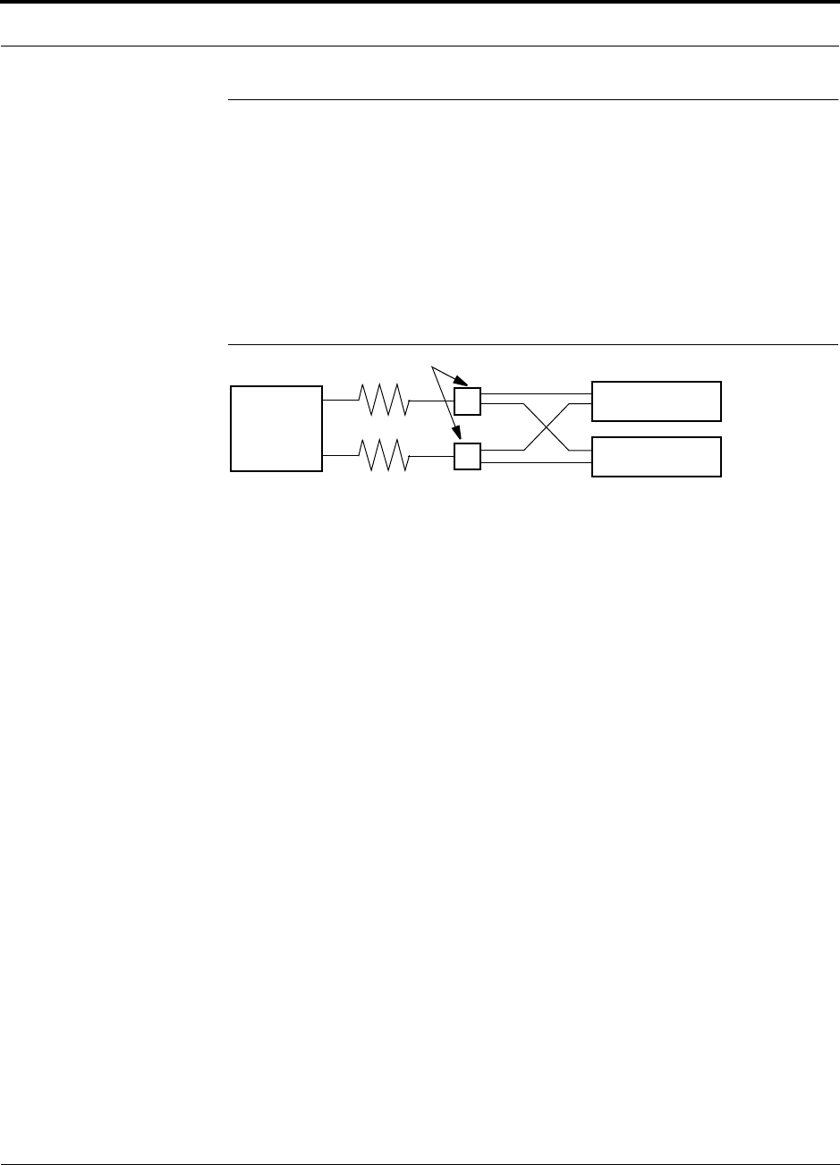
PN 8700-10 Help Hot Line (U.S. only): 1-800-530-9960 8-47
620003-0
PRELIMINARY Connecting a Main Hub to a Base Station
8.6 Connecting a Main Hub to a Base Station
The first consideration when connecting Unison Main Hubs to a base station is to
ensure there is an equal amount of loss through cables, combiners, etc. from the base
station to the Main Hubs. For this example, assume that the base station will have
simplex connections, one uplink and one downlink. Each of these connections will
need to be divided to equilibrate power for each Main Hub. For example, two Main
Hubs will require a 2×1 combiner/divider; four Main Hubs will require a 4×1 com-
biner/divider; and so on.
Figure 8-2 Connecting Main Hubs to a Simplex Base Station
When connecting a Unison Main Hub to a base station, also consider the following:
1. The downlink power from the base station must be attenuated enough so that the
power radiated by the RAU does not exceed the maximum power per carrier listed
in Section 8.1, “Maximum Output Power per Carrier at RAU,” on page 8-3.
2. The uplink attenuation should be small enough that the sensitivity of the overall
system is limited by Unison, not by the attenuator. However, some base stations
will trigger alarms if the noise or signal levels are too high. In this case the attenu-
ation will have to be large enough to prevent this from happening.
If, in an area covered by Unison, a mobile phone indicates good signal strength but
consistently has difficulty completing calls, it is possible that the attenuation between
Unison and the base station needs to be adjusted. In other words, it is possible that if
the uplink is over-attenuated, the downlink power will provide good coverage, but the
uplink coverage distance will be small.
When there is an excessive amount of loss between the Main Hub uplink and the base
station, the uplink system gain can be increased to as much as 15 dB to prevent a
reduction in the overall system sensitivity.
Base Station
2 × 1 combiner/divider
Downlink/Forward
Main Hub 1
Main Hub 2
Uplink/Reverse
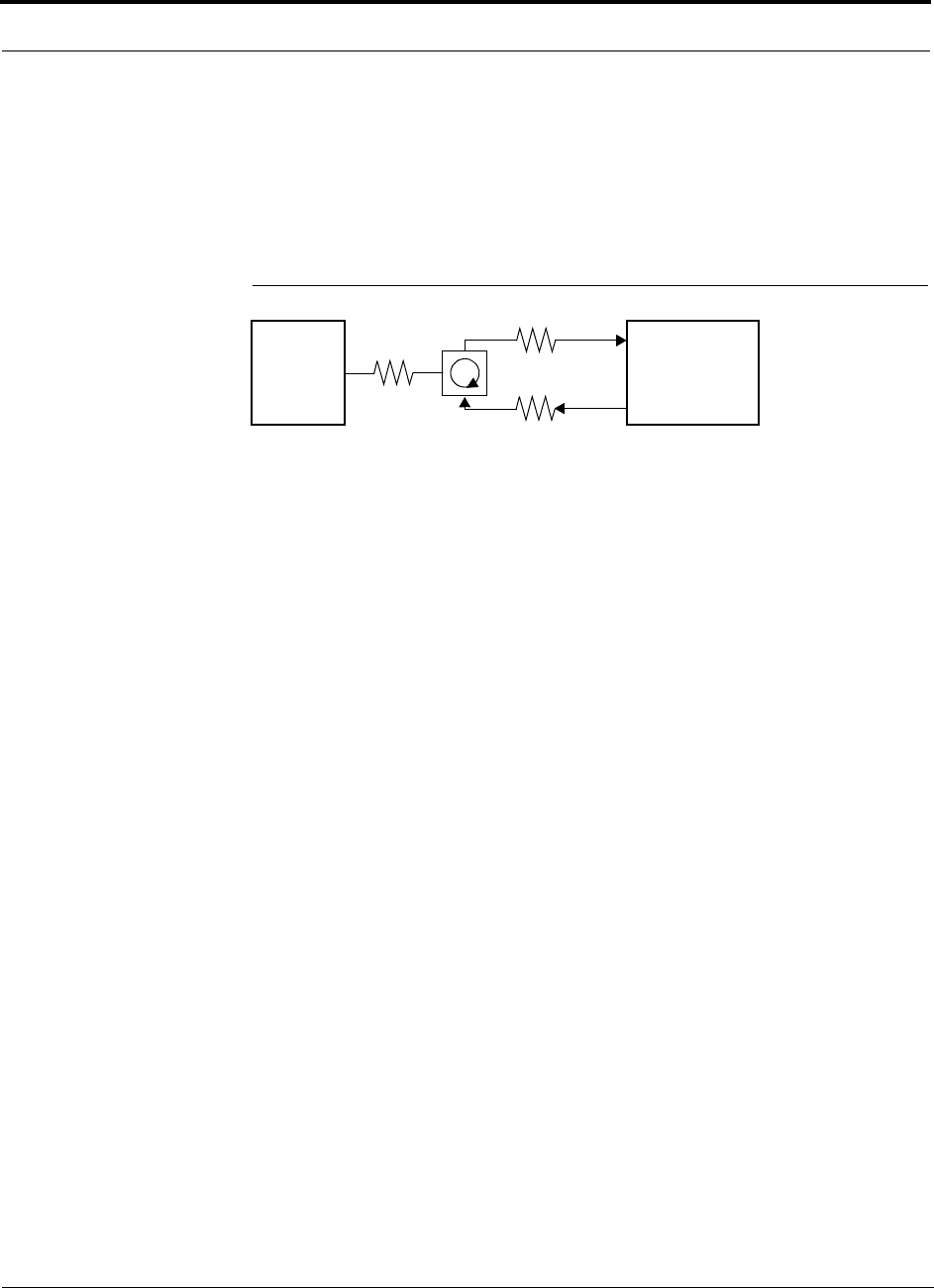
Designing a Unison Solution PRELIMINARY
8-48 InterReach Unison User Guide and Reference Manual PN 8700-10
620003-0
8.6.1 Attenuation
Figure 8-3 shows a typical setup wherein a duplex base station is connected to a Main
Hub. For a simplex base station, eliminate the circulator and connect the simplex
ports of the base station to the simplex ports of the Main Hub. Add attenuators to reg-
ulate the power appropriately.
Figure 8-3 Main Hub to Duplex Base Station or Repeater Connections
Duplex
Base Station Main Hub
Forward
Reverse
A3
A1
A2
• A typical circulator has an IP3 of +70dBm. If you drive the circulator too hard it will produce
intermods that are bigger than the intermods produced by Unison. The IP3 at the Forward
port input of the Main Hub is approximately +38 dBm. The IP3 of the circulator at that same
point (i.e., following attenuator A1) is +70dBm – A1. Thus, to keep the system IP3 from
being adversely affected by the circulator, attenuator A1 should be no more than approxi-
mately +30 dB.
• A filter diplexer can be used in place of the circulator. The IP3 of the diplexer can be
assumed to be greater than +100 dBm. If a diplexer is used, A3 can be omitted.
• A1+A3 should be chosen so that the output power per carrier at the RAU’s output is correct
for the number of carriers being transmitted. Suppose the base station transmits 36 dBm
per carrier and it is desired that the RAU output be 6 dBm per carrier and the forward port
gain is 0 dB. Then A1+A3=30 dB.
• A2+A3 should, ideally, be at least 10 dB less than the noise figure plus the gain of the Uni-
son system. For example, if the reverse port has a 0 dB gain and if there are 32 RAUs, the
noise figure is approximately 22 dB. So A2+A3 should be about 10 dB. If A2+A3 is too
large, the uplink coverage can be severely reduced.
• Given these three equations:
A1 < 30 dB
A1+A3 = 30 dB (in this example)
A2+A3 < 10 dB (in this example)
we could choose A1=20 dB, A2=0 dB, A3=10 dB
or
Repeater

PN 8700-10 Help Hot Line (U.S. only): 1-800-530-9960 8-49
620003-0
PRELIMINARY Uplink Attenuation
8.6.2 Uplink Attenuation
The attenuation between the Main Hub’s reverse port and the base station does two
things:
1. It attenuates the noise coming out of Unison.
2. It attenuates the desired signals coming out of Unison.
Setting the attenuation on the uplink is a trade-off between keeping the noise and
maximum signal levels transmitted from Unison to the base station receiver low
while not reducing the SNR (signal-to-noise ratio) of the path from the RAU inputs to
the base station inputs. This SNR can not be better than the SNR of Unison by itself,
although it can be significantly worse.
For example, suppose we have a GSM Unison system consisting of one Main Hub,
four Expansion Hubs, and 32 RAUs (1-4-32) with uplink NF=22 dB. (See Table 8-30
on page 8-38.) If we use 30 dB of attenuation between the Main Hub’s reverse port
and the base station (which has its own noise figure of about 4 dB), the overall noise
figure will be 34.3 dB (refer to the formula on page 8-36) which is 12.3 dB worse
than Unison by itself. That causes a 12.3 dB reduction in the uplink coverage dis-
tance. Now, if the attenuation instead is 10 dB, the cascaded noise figure is
NF=22.6 dB, which implies that the uplink sensitivity is limited by Unison, a desir-
able condition.
Rule of Thumb
A good rule of thumb is to set the uplink attenuation, A2+A3 in Figure 8-3 on
page 8-48, as follows:
A2+A3 ≈ Unison uplink NF + uplink gain (0 dB for reverse port) – BTS NF – 10dB
and round A2 down to the nearest convenient attenuation value.

Designing a Unison Solution PRELIMINARY
8-50 InterReach Unison User Guide and Reference Manual PN 8700-10
620003-0
8.6.2.1 Uplink Attenuation Exception: CDMA
In CDMA systems, the power transmitted by the mobile is determined by the charac-
teristics of both the uplink and downlink paths. The power transmitted by the mobile
should be similar in open-loop control (as determined by the downlink path) as dur-
ing closed-loop control (as determined by the uplink and downlink paths). In addi-
tion, the mobile’s transmit power when it communicates with a base station through
Unison should be similar to the power transmitted when it communicates with a base
station in the outdoor network (during soft hand-off). Because of these consider-
ations, you should not allow the downlink and uplink gains to vary widely.
Open-loop power control:
PTX = –76 dBm (for PCS) – PRX
where PTX is the power transmitted and PRX is the power received by the mobile. If
PL is the path loss (in dB) between the RAU and the mobile, and PDN is the downlink
power radiated by the RAU, then
PTX = –76 dBm (for PCS) – PDN + PL
Closed-loop power control:
PTX = noise floor + uplink NF – process gain + Eb/No + PL
= –113 dBm/1.25 Mhz + NF – 19 dB + 7 dB + PL
where Eb/No = 7 dB is a rough estimate, and NF is the cascaded noise figure of the
Unison uplink, the uplink attenuation, and the base station noise figure. Equating PTX
for the open-loop and closed-loop we see that
NF = 49 – PDN
where PDN is determined by the downlink attenuation. Since PDN for Unison is about
10 dBm, we see that the cascaded noise figure is about 39 dB, which is considerably
higher than that of Unison itself. This implies that we should use a fairly large attenu-
ation on the uplink. This case suggests using as much attenuation on the downlink as
on the uplink. The drawback of doing this is that the uplink coverage sensitivity is
reduced. A link budget analysis will clarify these issues. Typically, the uplink attenu-
ation between the Main Hub and the base station will be the same as, or maybe 10 dB
less than, the downlink attenuation.

PN 8700-10 Help Hot Line (U.S. only): 1-800-530-9960 8-51
620003-0
PRELIMINARY Designing for a Neutral Host System
8.7 Designing for a Neutral Host System
Designing for a neutral host system uses the same design rules previously discussed.
Since a neutral host system typically uses multiple systems in parallel, we find it best
to design for the worst case system so that there will not be holes in the covered area
and the economies of a single installation can be achieved. For example, as indicated
Section 7.1, the 1900 MHz RF signals do not propagate throughout a building as well
as the 800 MHz systems, therefore, we design to the 1900 MHz path loss formula.
8.7.1 Capacity of the Unison Neutral Host System
As indicated in Section 2.3, “System Bandwidths,” on page 2-10,
each Main Hub can support more than one sub-band of the Cellular
or PCS bands. The exception to this is the iDEN Main Hub, because
the SMR band is not split into sub-bands.
The 800 MHz Main Hub can support both the A band and the B band
simultaneously. Also, the 1800 MHz and 1900 MHz Main Hubs can
support two bands each (as the frequencies currently are allo-
cated).
For example, a neutral host system that consists of one iDEN, one
800 MHz, and two 1900 MHz systems can support up to seven sep-
arate service providers:
•1 on iDEN
• 2 on 800 MHz, A band and B band
• 2 in each 1900 MHz
Rich, what’s correct for Unison? JW

Designing a Unison Solution PRELIMINARY
8-52 InterReach Unison User Guide and Reference Manual PN 8700-10
620003-0
8.7.2 Example Unison Neutral Host System
Simon: do you have a Unison example? This is for LGCell. I need it
ASAP (Wednesday PM). Thanks, Julie
The following example configuration assumes:
• 0 dBm per carrier output
• Each System supports two bands, and therefore, two Operators
(Exception: iDEN supports one Operator)
Example Configuration:
• 800 MHz iDEN: System 1
l - iDEN system: 8 Channels, 23 voice calls
• 800 MHz Cellular: System 2
l - TDMA Band: 8 Channels, 23 voice calls
l - CDMA Band: 2 Channels, 30–40 voice calls
• 1900 MHz PCS: Systems 3 & 4 (2 band combinations/system)
l - TDMA Band: 8 Channels, 23 voice calls
l - CDMA Band: 2 Channels, 30–40 voice calls
l - GSM Band: 4 Channels, 31 voice calls
Number of subscribers1 that could be served in this example:
• 800 MHz Cellular: System 1
l - iDEN Operator: 23 voice calls, 315 subscribers
• 800 MHz Cellular: System 2
l - TDMA Operator: 23 voice calls, 315 subscribers
l - CDMA Operator: 30–40 voice calls, 438–620 subscribers
• 1900 MHz PCS: Systems 3 & 4 (2 band combinations/system)
l - TDMA Operator: 23 voice calls, 315 subscribers
l - CDMA Operator: 30–40 voice calls, 438–620 subscribers
l - GSM Operator: 31 voice calls, 456 subscribers
This configuration supports growth for up to 7 Operators.
1. Based on Standard Erlang B 2% GOS requirement. Each user has a 0.05 wireless Erlang which is higher than the standard 0.035
wireless Erlang.

PN 8700-10 InterReach Unison User Guide and Reference Manual 9-1
620003-0
PRELIMINARY
SECTION 9 Replacing Unison Components
in an Operating System
9.1 Replacing an RAU
Be aware that the new RAU must be the same band as the one you are replacing. If
you replace an RAU with one that is of the wrong band, it will not work.
The Main Hub automatically checks the band of a replaced RAU. There is no need to
issue commands directly from the Main Hub. Therefore, as long as the RAU is of the
correct band, the system will operate properly.
Replacing an RAU
1. Use AdminManager or refer to the As-Built Document to review the current
RAU’s configuration.
2. Disconnect the Cat-5/6 cable and antenna from the unit to be replaced.
3. Install the new RAU.
4. Connect the antenna and then the Cat-5/6 cable to the new RAU
AdminManager Tasks
• Use the Advanced RAU Settings option on the Configuration & Maintenance
panel to set the RAU’s 10 dB attenuation and UL ALC settings.
• When convenient, perform System Test to optimize performance.
During System Test, the entire system is temporarily off-line and no RF is
being transmitted.

Replacing Unison Components in an Operating System PRELIMINARY
9-2 InterReach Unison User Guide and Reference Manual PN 8700-10
620003-0
Checking the RAU’s LEDs
1. The RAU’s LINK and ALARM LEDs should blink (green/red) on power up.
• If the LEDs do not blink on power up, replace the RAU.
2. After several seconds both LEDs should change to green, which indicates that the
unit has been successfully replaced, there is communication with the Expansion
Hub, and the RAU band is correct.
a. If the LINK LED remains green and the ALARM LED remains red, verify that
the RAU model is correct for the intended frequency band.
– Disconnect the cable and then reconnect it once; doing this more than once
will not change the result.
b. If both LEDs still don’t change to green, use the AdminManager to determine
the exact nature of the fault and see a recommendation of how to correct it.
c. If both LEDs turn red (after 45 seconds), the Expansion Hub has terminated
communications.

PN 8700-10 Help Hot Line (U.S. only): 1-800-530-9960 9-3
620003-0
PRELIMINARY Replacing an Expansion Hub
9.2 Replacing an Expansion Hub
Replacing an Expansion Hub
1. Turn off the power to the Expansion Hub.
2. Disconnect all Cat-5/6 cables, both fiber cables, and the AC power cord.
3. Replace the Expansion Hub with a new one.
4. Connect the AC power cord, all Cat-5/6 cables, and both fiber cables – remember-
ing to clean and correctly connect the uplink and downlink fiber.
5. Turn on the power to the Expansion Hub.
AdminManager Tasks
• The Main Hub automatically issues the band setting.
• When convenient, perform System Test to optimize performance.
During System Test, the entire system is temporarily off-line and no RF is
being transmitted.
Checking the Expansion Hub’s LEDs
• The LEDs should blink through all states on power up.
• If the LEDs do not blink on power up, replace the Expansion Hub.
• If the LEDs do not illuminate at all, make sure the AC power cable is con-
nected.
•The
UL STATUS and DL STATUS LEDs should be green.
•The
E-HUB STATUS and POWER LEDs should be green.
• For each RJ-45 port that has an RAU connected:
•The
E-HUB/RAU LEDs should be green.
•The
LINK LEDs should be green.
It can take several seconds for each Cat-5/6 connection for the LEDs to display
properly.
NOTE: Refer to Section 10 for troubleshooting using the LEDs.

Replacing Unison Components in an Operating System PRELIMINARY
9-4 InterReach Unison User Guide and Reference Manual PN 8700-10
620003-0
9.3 Replacing a Main Hub
You must record the system configuration settings from the old Main Hub’s memory
before replacing the unit. You will program the new Main Hub with this information.
If the Main Hub is programmed incorrectly, the system will not work. If the Main
Hub is not functioning, get the configuration settings from the As-Built Document
that was created as part of the original installation.
Get System Configuration Settings
1. Connect the null modem cable to the PC and the Main Hub.
2. Start the AdminManager software.
3. Select the Configuration & Maintenance Panel option from the introductory win-
dow.
4. Click the SAVE CONFIG button.
The Save Configuration Notes dialog box is displayed.
5. Type any notes you want to save with the configuration settings into the dialog
box and click OK.
The configuration settings are saved in a text file, for example:
Begin Notes *******************************************
LGC HQ
05/23/01 MH configuration L010MH11
System configuration
End Notes *********************************************
Frequency Band is DCS Low.
SystemGain:UL=12dB,DL=4dB.
Callback Number is 1234567.
System label is LGC.
Main Hub Information:
Serial Number: L010BMH1
Part Number: 7405101
Revision Number: 03
Firmware Revision: 010526
Expansion Hub LGC-1 Information:
Serial Number: L010BEH9
Part Number: 7405101
Revision Number: 03
Firmware Revision: 010513
RAU LGC-1-5 Information:
Serial Number: L010BRU1
Part Number: 7405101
Revision Number: 03
Firmware Revision: 010021

PN 8700-10 Help Hot Line (U.S. only): 1-800-530-9960 9-5
620003-0
PRELIMINARY Replacing a Main Hub
Replacing a Main Hub
1. Turn off the power to the Main Hub.
2. Disconnect all fiber cables and the AC power cord.
3. Replace the Main Hub with a new one.
4. Connect the AC power cord and all fiber cables – remembering to clean and cor-
rectly connect the uplink and downlink fiber cables.
5. Connect the null modem cable to the PC and then to the Main Hub’s front panel
DB-9 serial connector.
6. Start the AdminManager software.
7. Select the Installation Wizard option from the introductory window.
8. Turn on the power to the Main Hub.
AdminManager Tasks
• Use the Installation Wizard to:
• Set the Operation Band
• Use the Configuration & Maintenance panel to:
• Set Callback Number
• Set Contact Sense Properties
• Set System Parameters
• Perform System Test
During the System Test the system is out-of-service and no RF is being trans-
mitted. Choose a time of day to perform the System Test that will have the least
impact on the system.

Replacing Unison Components in an Operating System PRELIMINARY
9-6 InterReach Unison User Guide and Reference Manual PN 8700-10
620003-0
Checking the Main Hub’s LEDs
• The LEDs should blink through all states on power up.
• If the LEDs do not blink on power up, replace the Main Hub.
• If the LEDs do not illuminate at all, make sure the AC power cable is con-
nected.
• For each fiber optic port that has a Main Hub connected:
•The
LINK LED should be green.
•The
E-HUB/RAU LED should be:
– Green if the MAIN HUB STATUS is green.
– Red if the MAIN HUB STATUS is red.
•The
MAIN HUB STATUS LED should be:
• Red if the Main Hub is new from the factory and a band has not been pro-
grammed, or if the wrong band is programmed.
• Green if the Main Hub was previously programmed with a correct band
(matches the RAUs in the system).
NOTE: If there is communication between the Main Hub and the Expansion Hubs,
use the AdminManager software’s Configuration & Maintenance panel to isolate sys-
tem problems.

PN 8700-10 InterReach Unison User Guide and Reference Manual 10-1
620003-0
PRELIMINARY
SECTION 10 Maintenance, Troubleshooting,
and Technical Assistance
There are no user-serviceable parts in any of the Unison components. Faulty or failed
components are fully replaceable through LGC Wireless.
Address 2540 Junction Avenue
San Jose, California
95134-1902 USA
Phone 1-408-952-2400
Fax 1-408-952-2410
Help Hot Line 1-800-530-9960 (U.S. only)
+1-408-952-2400 (International)
+44(0) 1223 597812 (Europe)
Web Address http://www.lgcwireless.com
e-mail service@lgcwireless.com
10.1 Maintenance
No periodic maintenance of the Unison equipment is required.

Maintenance, Troubleshooting, and Technical Assistance PRELIMINARY
10-2 InterReach Unison User Guide and Reference Manual PN 8700-10
620003-0
10.2 Troubleshooting
NOTE: Unison has no user-serviceable parts. Faulty or failed units are fully
replaceable through LGC Wireless.
Sources of potential problems include:
• Malfunction of one or more Unison components
• Faulty cabling/connector
• Antenna, base station, or repeater problem
• External RF interface
NOTE: Faulty cabling is the cause of a vast majority of problems. All
Cat-5/6 cable should be tested to TIA/EIA 568-A specifications.
It is recommended that you use the AdminManager for troubleshooting the system,
and use the LEDs as backup or for confirmation. However, if there are communica-
tion problems within the system, the LEDs may provide additional information that is
not available using AdminManager.
To begin troubleshooting, use the AdminManager software to determine the current
faults and warnings for all of the units in the system. To troubleshoot, start with the
Main Hub’s faults and warnings, then proceed to each of the Expansion Hubs, finish-
ing with each of the RAUs.
If you do not have a PC with AdminManager available, the LEDs provide a minimal
set of diagnostic information.
If you cannot determine the cause of a problem after following the recommended pro-
cedures, call LGC Wireless customer help hot line:
1-800-530-9960 (U.S. only)
+1-408-952-2400 (International)
+44(0) 1223 597812 (Europe)

PN 8700-10 Help Hot Line (U.S. only): 1-800-530-9960 10-3
620003-0
PRELIMINARY Fault Indications
10.2.1 Fault Indications
Once all of the units are powered on and the cable connections are made, the faults
from each unit can be requested using the AdminManager. Start with the Main Hub
and work downstream.
Resolve all faults first and then check the warnings. Take appropriate action to
resolve the faults, as indicated in the following tables.
Main Hub Faults
Table 10-1 Main Hub Faults
Fault Message LED State Possible Causes Action Impact
Hardware failure. STATUS Red Internal hardware
failure.
Replace the Main Hub. System off-line.
Frequency band
not programmed.
STATUS Red Factory default. Program the frequency band
using the AdminManager’s
Installation Wizard.
System off-line.
Main Hub is over
temperature.
STATUS Red Fan failure.
Ambient tempera-
ture is above maxi-
mum.
If fan is not operating, replace
the Main Hub.
If fan is operating, check room
environmental controls.
Possible unit failure.
Failed to perform
system test.
STATUS Red Internal failure. Replace the Main Hub when
possible.
Degraded performance.
Uplink EHn AGC
failure.
STATUS Red Uplink fiber has
high optical loss.
Main Hub uplink
port failure.
Measure UL optical fiber loss.
Clean the Main Hub’s uplink
fiber port.
Move fiber pair to another
port. If fault is not reported,
fiber is okay and MH port is
dirty or bad. Use the Admin-
Manager to ‘Clear All Discon-
nect Status’ to clear the
disconnect fault on the origi-
nal port.
The Main Hub’s EHn
port is off-line; down-
link is okay.

Maintenance, Troubleshooting, and Technical Assistance PRELIMINARY
10-4 InterReach Unison User Guide and Reference Manual PN 8700-10
620003-0
No communica-
tion with EHn.
LINK Red Downlink fiber has
high optical loss.
Expansion Hub
downlink port fail-
ure.
Main Hub internal
failure.
If common point of failure for
more than one Expansion
Hub, replace the Main Hub.
Measure downlink optical
fiber loss.
Clean the Expansion Hub’s
downlink fiber port.
Clean the Main Hub’s down-
link fiber port.
Move the Main Hub fiber pair
to another port. If fault is not
reported, fiber is okay and the
Main Hub port is dirty or bad.
Use the AdminManager’s
“Clear All Disconnect Status”
command to clear the discon-
nect fault on the original port.
EHn and connected
RAUs are off-line.
E-HUB/
RAU Off
EHn disconnected. LINK Red The Expansion Hub
was connected and
is now discon-
nected.
The uplink fiber
optical loss exceeds
minimum threshold.
Expansion Hub
uplink laser failure.
If EHn is disconnected, recon-
nect it or clear the disconnect
fault using the AdminMan-
ager’s “Clear All Disconnect
Status” command.
If EHn is connected, check the
uplink fiber cable’s optical
loss.
Clean the Main Hub’s uplink
port.
Clean EHn’s uplink port.
Check that EHn’s uplink laser
is operational.
EHn and connected
RAUs are off-line.
E-HUB/
RAU Off
EHn/RAU reports
fault condition.
LINK Green Any EH or RAU
fault
Use the AdminManager to
check for Expansion Hub and
RAU faults. Proceed to
Expansion Hub or RAU trou-
bleshooting section.
EHn and/or RAU
off-line
E-HUB/
RAU Red
Table 10-1 Main Hub Faults (continued)
Fault Message LED State Possible Causes Action Impact

PN 8700-10 Help Hot Line (U.S. only): 1-800-530-9960 10-5
620003-0
PRELIMINARY Fault Indications
Expansion Hub Faults
Table 10-2 Expansion Hub Faults
Fault Message LED State Possible Causes Action Impact
Hardware failure. STATUS Red Expansion Hub internal
hardware failure.
Main Hub inter-
nal hardware
failure. ? (JS)
Downlink fiber has
high optical loss.
If common point of failure for
more than one Expansion Hub,
replace the Main Hub.
Measure downlink optical fiber
loss.
Clean the Expansion Hub’s
downlink fiber port.
Clean the Main Hub’s down-
link fiber port.
Replace the Expansion Hub.
Expansion Hub and
connected RAUs
are off-line
PLL unlock. STATUS Red Internal hardware fail-
ure.
Replace the Expansion Hub. Expansion Hub and
connected RAUs
are off-line
Frequency band
not programmed.
STATUS Red Internal hardware fail-
ure.
Cycle power on the Expansion
Hub. If fault persists, replace
the Expansion Hub.
Expansion Hub and
connected RAUs
are off-line
Expansion Hub is
over temperature.
STATUS Red Fan failure(s).
Ambient temperature
above maximum
If fans are not operating,
replace the Expansion Hub.
If fans are operating, check
room environmental controls.
Expansion Hub and
connected RAUs
are off-line.
RAUs are com-
manded off-line
which disables their
power amplifiers. If
the Expansion Hub
temperature does
not start to drop, the
Expansion Hub will
disable DC power
to all RAUs.
Downlink pilot
failure.
STATUS Red Downlink fiber has
high optical loss.
MH downlink port fail-
ure.
EH downlink port fail-
ure.
MH internal hardware
failure.
EH internal hardware
failure.
If common point of failure for
more than one EH, replace MH.
Measure DL optical fiber loss.
Clean MH downlink fiber port.
Clean EH downlink fiber port.
Replace EH.
EH and connected
RAUs are off-line.

Maintenance, Troubleshooting, and Technical Assistance PRELIMINARY
10-6 InterReach Unison User Guide and Reference Manual PN 8700-10
620003-0
Failed to perform
system test.
STATUS Red Internal failure.
Main Hub internal fail-
ure.
If common point of failure for
more than one Expansion Hub,
replace the Main Hub.
Replace the Expansion Hub
when possible.
Degraded perfor-
mance.
Uplink RAUn
AGC failure.
Universal or
particular
RAU port?
(JS)
LINK Red Cat-5/6 cable length.
Expansion Hub uplink
port failure.
Expansion Hub internal
failure.
Check Cat-5/6 cable length.
Move RAU to another port. If
no fault reported, replace the
Expansion Hub. If fault
reported, replace RAU.
Expansion
Hub and con-
nected RAUs
are off-line.
RAU Off
No communica-
tion with RAUn
LINK Red Cat-5/6 cable failure.
RAU internal failure.
Expansion Hub port
failure.
Verify Cat-5/6 cable has no
shorts or opens.
Move RAU to another port. If
fault persists, replace RAU,
else replace the Expansion
Hub.
RAUn is off-line.
RAU Off
RAUn over cur-
rent
LINK Green Cat-5/6 cable failure.
RAU internal failure.
Verify Cat-5/6 cable has no
shorts or opens.
Move RAU to another port. If
fault persists, replace RAU. If
no fault reported, remove RAU,
power cycle the Expansion
Hub, connect known good
RAU to port. If fault reported,
replace the Expansion Hub.
RAUn is off-line.
RAU Red
Table 10-2 Expansion Hub Faults (continued)
Fault Message LED State Possible Causes Action Impact

PN 8700-10 Help Hot Line (U.S. only): 1-800-530-9960 10-7
620003-0
PRELIMINARY Fault Indications
Remote Access Unit Faults
Table 10-3 Remote Access Unit Faults
Fault Message LED State Possible Causes Action Impact
Hardware fail-
ure.
ALARM Red Internal hardware failure. Replace the RAU. RAU is off-line.
Frequency band
not programmed.
ALARM Red Wrong version of RAU for
frequency band desired.
Replace the RAU if not valid
for desired frequency band.
RAU is off-line.
RAU is over
temperature.
ALARM Red Ambient temperature
above maximum.
Check environmental controls;
move the RAU to cooler envi-
ronment.
RAU is off-line.
Power supplied
by EH is too
low.
ALARM Red Cat-5/6 cable failure.
RAU internal failure.
Expansion Hub internal
failure.
Verify Cat-5/6 cable has no
shorts or opens.
Move the RAU cable to another
Expansion Hub port. If fault
persists, replace the RAU; oth-
erwise, replace Expansion Hub.
RAU is off-line.
Power supplied
by EH is too
high.
ALARM Red Cat-5/6 cable failure.
Expansion Hub internal
failure.
RAU internal failure.
Verify Cat-5/6 cable has no
shorts or opens.
Move RAU cable to another
Expansion Hub port. If fault
persists, replace the RAU, oth-
erwise replace the EH.
RAU is off-line.
Cat-5/6 cable too
long.
ALARM Red Cat-5/6 cable is too long. Verify Cat-5/6 cable has no
shorts or opens.
Verify maximum Cat-5/6 cable
length of 150 meters.
RAU is off-line.
Downlink pilot
failure.
Could this
also be a
problem
with the EH
port? (JS)
ALARM Red Cat-5/6 cable failure.
RAU internal failure.
Verify Cat-5/6 cable has no
shorts or opens.
Verify maximum Cat-5/6 cable
length of 150 meters.
Verify minimum Cat-5/6 cable
length of 10 meters.
RAU is off-line.

Maintenance, Troubleshooting, and Technical Assistance PRELIMINARY
10-8 InterReach Unison User Guide and Reference Manual PN 8700-10
620003-0
10.2.2 Warning Indications
Warnings alert you to conditions that may impact system performance and conditions
that indicate potential system failure.
Before addressing warnings, ensure that all faults are resolved. Take appropriate
action to resolve the warnings, as indicated in the following tables.
Main Hub Warnings
Table 10-4 Main Hub Warnings
Warning Message Action Impact
Downlink laser is failing. Replace the Main Hub when possible. The downlink laser will eventually fail and
the system will be off-line.
Temperature is high. Check room environmental controls. Potential Main Hub failure.
Fan failure. Check the Main Hub fan for rotation, air
flow blockage, dust; replace the Main Hub
if temperature rises.
Temperature may rise to fault level result-
ing in Main Hub and connected Expansion
Hub(s) and RAU(s) being off-line.
Portn uplink fiber optical loss
greater than recommended maxi-
mum.
Check the uplink fiber cable for optical
loss.
Clean the cable connector.
Clean the fiber ports.
Degraded system performance.

PN 8700-10 Help Hot Line (U.S. only): 1-800-530-9960 10-9
620003-0
PRELIMINARY Warning Indications
Expansion Hub Warnings
Remote Access Unit Warnings
Table 10-5 Expansion Hub Warnings
Warning Message Action Impact
Downlink fiber optical
loss greater than recom-
mended maximum.
Check the downlink fiber cable for excessive
optical loss.
Clean the cable connector.
Clean the fiber ports.
Degraded system performance.
Uplink laser is failing. Replace the Expansion Hub when possible. The uplink laser will eventually fail resulting in
the Expansion Hub and connected RAUs being
off-line.
Temperature is high. Check room environmental controls. Potential Expansion Hub failure.
Fan failure(s). Check the Expansion Hub fans for rotation,
air flow blockage, dust; replace the Expan-
sion Hub if temperature rises.
Temperature may rise to fault level resulting in
the Expansion Hub and connected RAUs being
off-line.
Cat-5/6 cable between
EH and RAU is greater
than recommended
maximum.
Check that the Cat-5/6 cable does not exceed
the recommended maximum length.
Degraded system performance.
Table 10-6 Remote Access Unit Warnings
Warning Message Action Impact
Temperature is high. Move the RAU to cooler environment. Potential RAU failure.
DC voltage is low. Check the Cat-5/6 cable for shorts and opens.
Replace the RAU when possible.
RAU at minimum voltage setting
for proper operation. not an impact
(JS)
Power amplifier is fail-
ing.
Replace the RAU when possible. Potential RAU failure.
Cat-5/6 cable between
EH and RAU is greater
than recommended
maximum.
Check that the Cat-5/6 cable does not exceed
the recommended maximum length.
Degraded system performance.
Antenna disconnected. Check the RAU SMA antenna connection. Poor RAU coverage.

Maintenance, Troubleshooting, and Technical Assistance PRELIMINARY
10-10 InterReach Unison User Guide and Reference Manual PN 8700-10
620003-0
10.3 LED Troubleshooting Guide
The following troubleshooting guide is from the perspective that all Unison equip-
ment is installed, their cables are connected, and they are powered on; it is assumed
that the system was operating normally before the current problem. (Refer to
Section 6 for information on troubleshooting during initial installation of the system.)
Always use AdminManager, if possible, to troubleshoot the system. The LEDs are for
backup troubleshooting; although, an Expansion Hub uplink laser failure can only be
resolved using the EH UL STATUS LED.
Begin with troubleshooting the Main Hub’s LEDs and then the Expansion Hub’s
LEDs. The RAU LEDs probably will not provide additional information for trouble-
shooting.

PN 8700-10 Help Hot Line (U.S. only): 1-800-530-9960 10-11
620003-0
PRELIMINARY Troubleshooting Main Hub LEDs During Normal Operation
10.3.1 Troubleshooting Main Hub LEDs During Normal Operation
• All of the Main Hub’s LEDs should be green during normal operation. If any
LEDs are red, get status using the AdminManager software for the exact cause and
recommendations.
Table 10-7 Troubleshooting Main Hub Port LEDs During Normal Operation
During
Normal
Operation LED State Action Impact
Expansion
Hub Not
Connected
LINK Red If the Expansion Hub was discon-
nected accidentally, re-connect the
cables. The LEDs should change to
Green/Red (then Green/Green, after
20 seconds, if the Main Hub band
has been programmed).
If the Expansion Hub is to be
removed from service permanently,
then use the AdminManager’s ‘Clear
All Disconnect States’ command to
clear all disconnect states to no con-
nect states. The Main Hub’s port
LEDs should change to Off/Off.
Expansion Hub was previously con-
nected, but it is not currently con-
nected; Expansion Hub cable
disconnect.
The AdminManager software will clear
all disconnects caused by installation
as part of the clean-up process. After
installation, power cycle the Main Hub
or use the AdminManager’s ‘Clear All
Disconnect States’ command.
E-HUB/RAU Off
Expansion
Hub
Connected
LINK Red Use the AdminManager to determine
the exact cause of the Main Hub’s
faults.
Lost communication with Expansion
Hub; could be Expansion Hub problem
or fiber cable problem.
E-HUB/RAU Off
LINK Green Expansion Hub or connected RAU
reports a fault condition; use the
AdminManager to determine the
exact cause of the Expansion Hub
and RAU’s faults.
E-HUB/RAU Red
Table 10-8 Troubleshooting Main Hub Status LEDs During Normal Operation
During
Normal
Operation LED State Action Impact
At Any
Time
MAIN HUB
STATUS Red Use the AdminManager to determine
the exact cause of the fault.
Power cycle one time. If fault
remains, replace the Main Hub.
Internal Main Hub fault.
MAIN HUB
STATUS Alternating
Red/Green
Reduce input signal power; reduce
system gain.
Signal compression.

Maintenance, Troubleshooting, and Technical Assistance PRELIMINARY
10-12 InterReach Unison User Guide and Reference Manual PN 8700-10
620003-0
10.3.2 Troubleshooting Expansion Hub LEDs During Normal Operation
• All of the Expansion Hub LINK and E-HUB/RAU LEDs that have RAUs connected
should be Green/Green, indicating that the RAU is powered on, communication is
established, and operation is normal.
•The
POWER and MAIN HUB STATUS LEDs should both be Green.
Table 10-9 Troubleshooting Expansion Hub Port LEDs During Normal
Operation
During
Normal
Operation Port LEDs State Action Impact
RAU is not
connected
LINK Red If the RAU was disconnected acci-
dentally, re-connect the Cat-5/6
cable. The Expansion Hub’s port
LEDs should change to Green/Red
(then Green/Green, after 20 sec-
onds, if the Main Hub is connected,
powered on, and has band pro-
grammed).
If you are removing the RAU from
service permanently, then com-
mand ‘Clear All Disconnect States’
using the AdminManager soft-
ware. The Expansion Hub’s port
LEDs should change to Off/Off.
RAU was previously connected, but it is
not currently connected; RAU cable is
disconnected.
RAU Off
RAU is
connected
LINK Red Disconnect/reconnect the Cat-5/6
cable to force power-on reset to the
RAU. If the port LEDs remain
Red/Off, check the Expansion Hub
faults using the AdminManager for
the exact cause.
Lost communications with the RAU. The
RAU could have powered down due to
over current; cable could have been dam-
aged.
RAU Off
LINK Green RAU reports a fault condition;
check the Expansion Hub faults
using the AdminManager for the
exact cause.
Depends on the fault condition.
RAU Red

PN 8700-10 Help Hot Line (U.S. only): 1-800-530-9960 10-13
620003-0
PRELIMINARY Troubleshooting Expansion Hub LEDs During Normal Operation
Table 10-10 Troubleshooting Expansion Hub Status LEDs During Normal
Operation
During
Normal
Operation EH Status
LEDs State Action Impact
At Any
Time
(JS)
UL STATUS Red Replace the Expansion Hub Uplink laser failure; no communications
between the Main Hub and the Expansion
Hub
DL STATUS Red Check the downlink fiber for opti-
cal loss
No communications with the Main Hub
E-HUB
STATUS Red If either the UL STATUS or the DL
STATUS are also red, see above.
Cycle power on the Expansion
Hub. If fault remains, replace the
Expansion Hub.
Internal Expansion Hub fault (including
either of the above UL STATUS or DL
STATUS states)

Maintenance, Troubleshooting, and Technical Assistance PRELIMINARY
10-14 InterReach Unison User Guide and Reference Manual PN 8700-10
620003-0
10.4 Technical Assistance
Call our help hot line for technical assistance:
1-800-530-9960 (U.S. only)
+1-408-952-2400 (International)
+44(0) 1223 597812 (Europe)
Leave your name and phone number and an LGC Wireless customer service repre-
sentative will return your call within an hour. Be prepared to provide the following
information when you receive the return call:
• Company name
• End user name
• Type of system, model number, frequency
• Approximate time in service (warranty), sales order number
• Description of problem
• LED status
• AdminManager fault and warning status

PN 8700-10 InterReach Unison User Guide and Reference Manual A-1
620003-0
PRELIMINARY
APPENDIX A Cables and Connectors
A.1 Cat-5/6 Cable (ScTP)
• Connects the Expansion Hub to the RAU(s)
• Transmits (downlink) and receives (uplink) cellular and PCS signals
• Delivers DC electrical power to the RAUs. The Expansion Hub’s DC voltage out-
put is 36V DC nominal. A current limiting circuit is used to protect the Expansion
Hub if it reaches its current limit
• Use shielded RJ-45 connectors
• Distances:
• Absolute Minimum: 10 meters (33 ft)
• Recommended Minimum: 25 meters (82 ft)
• Recommended Maximum: 100 meters (328 ft)
• Absolute Maximum: 150 meters (492 ft)
There are four separate twisted pairs in one Cat-5/6 screened twisted pair (ScTP)
cable. The ScTP cable loss described in this document is for Cat-5 Mohawk/CDT
55986 or Belden 1624P DataTwist Five cable, or equivalent. The following table lists
the functional assignment of the pairs:
Table A-1 Cat-5/6 Twisted Pair Assignment
Pair (wire number) Function
1 & 2 Clock and Input Voltage
3 & 6 RS485
4 & 5 Uplink IF, UL Pilot and Ground
7 & 8 Downlink IF, DL Pilot and Ground
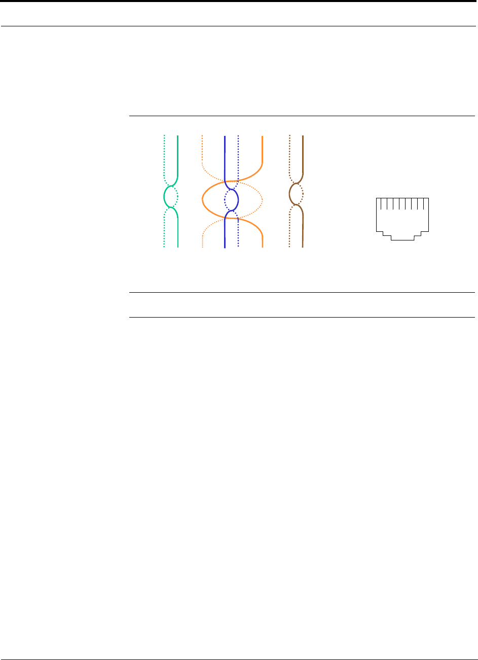
Cables and Connectors PRELIMINARY
A-2 InterReach Unison User Guide and Reference Manual PN 8700-10
620003-0
All Cat-5/6 cable must be terminated according to the TIA/EIA 568-A standard. The
following diagram shows the top view of the wiring map for the cable and how the
four pairs should be terminated.
Figure A-1 Wiring Map for Cat-5/6 Cable
NOTE: Be sure to test cable termination before installing the cable.
The nominal DC impedance of the Cat-5/6 cable is 0.08 ohm/meter and the nominal
RF impedance is 100 ohm.
12 3 45 6 78
Brown
Brown/
White
Blue Blue/
White
Green/
White
Green Orange
Orange/
White
RJ-45 Port
12345678
W-G
G
W-O
BL
W-BL
O
W-BR
BR

PN 8700-10 Help Hot Line (U.S. only): 1-800-530-9960 A-3
620003-0
PRELIMINARY Fiber Optical Cables
A.2 Fiber Optical Cables
• Connects Main Hub to Expansion Hub(s)
• Transmits (downlink) and receives (uplink) cellular and PCS signals
• Use industry-standard 62.5µm/125µm MMF or Corning SMF-28 fiber, or equiva-
lent (SC/APC [angle-polished] connectors only)
• Distances:
• Multimode Fiber: up to 1.5 km (4,921 ft) – 3 dB optical loss maximum
• Single-Mode Fiber: up to 6 km (19,685 ft) – 3 dB optical loss maximum
A.3 Coaxial Cable
• Connects a Main Hub to a repeater or base station (N-type connectors)
• Connects an RAU to a passive antenna (SMA connectors)

Cables and Connectors PRELIMINARY
A-4 InterReach Unison User Guide and Reference Manual PN 8700-10
620003-0

PN 8700-10 InterReach Unison User Guide and Reference Manual B-1
620003-0
PRELIMINARY
APPENDIX B Compliance
B.1 Safety Requirements
All of the safety requirements are in process:
• UL/cUL 1950 3rd edition
• CB scheme evaluation with all national deviations
• EN 60950:1992 including amendments A1, A2, A3, A4, and A11

Compliance PRELIMINARY
B-2 InterReach Unison User Guide and Reference Manual PN 8700-10
620003-0
B.2 Radio/EMC Requirements
All anticipated standards approvals listed below are pending.
GSM/EGSM/DCS Products
Radio: EN 301502 v.7.0.1 (8-2000)
EMC: EN 301489-8
CISPR22
CISPR24
Cellular Products
FCC part 15 class A
FCC part 22
PCS Products
FCC part 15 class A
FCC part 24
iDEN Products
FCC part 15 class A
FCC part 90
GSM Products
FCC part 15 class A
FCC part 90

PN 8100-50 InterReach Unison User Guide and Reference Manual C-1
620004-0
PRELIMINARY
APPENDIX C Glossary
Air Interface A method for formatting data and voice onto radio waves. Common
air interfaces include AMPS, TDMA, CDMA, and GSM.
AIN Advanced Intelligent Network. AINs allow a wireless user to make and receive
phone calls while roaming outside the user’s “home” network. These networks,
which rely on computers and sophisticated switching techniques, also provide
many Personal Communications Service (PCS) features.
Amplitude The distance between high and low points of a waveform or signal.
AMPS Advanced Mobile Phone Service. AMPS is an analog cellular FDMA sys-
tem. It was the basis of the first commercial wireless communication system in
the U.S and has been used in more than 35 other countries worldwide.
Analog The original method of modulating radio signals so they can carry informa-
tion which involves transmitting a continuously variable signal. Amplitude Mod-
ification (AM) and Frequency Modulation (FM) are the most common methods
of analog modulation.
ANSI The American National Standards Institute. A nonprofit, privately funded
membership organization founded in 1918 that reviews and approves standards
developed by other organizations.
Antenna A device for transmitting and/or receiving signals.
Attenuation The decrease in power that occurs when any signal is transmitted.
Attenuation is measured in decibels (dB).
Backhaul A term applied to the process of carrying wireless traffic between the
MSC and the base station.
Base Station The radio transmitter/receiver that maintains communications with
mobile devices within a specific area.
BSC Base Station Controller. A GSM term referring to the device in charge of man-
aging the radio interface in a GSM system, including the allocation and release of
radio channels and hand-off of active calls within the system.

Glossary PRELIMINARY
C-2 InterReach Unison User Guide and Reference Manual PN 8100-50
620004-0
BTA Basic Trading Area. The U.S. and its territories are divided into 493 areas,
called BTAs. These BTAs are composed of a specific list of counties, based on a
system originally developed by Rand McNally. The FCC grants licenses to wire-
less operators to provide service within these BTAs and/or MTAs. (See MTA.)
BTS Base Transceiver Station. A GSM term referring to the group of network
devices that provide radio transmission and reception, including antennas.
C/I Carrier to interference ratio. The ratio of the desired signal strength to the com-
bined interference of all mobile phones using the system. Usually, the interfer-
ence of most concern is that provided by mobile phones using the same channel
in the system. These are referred to as “co-channel interferers.”
CCITT Consultative Committee on International Telephone and Telegraph. This
organization sets international communications standards. The CCITT is now
known as ITU (the parent organization).
CDMA Code Division Multiple Access. A digital wireless access technology that
uses spread-spectrum techniques. Unlike alternative systems, such as GSM, that
use time-division multiplexing (TDM), CDMA does not assign a specific fre-
quency to each user. Instead, every channel uses the full available spectrum.
Individual conversations are assigned a unique code which allows the conversa-
tion to be spread out over multiple channels; transmitted to the far end; and
re-assembled for the recipient using a specific code.
CDPD Cellular Digital Packet Data. CDPD allows data transmission over the ana-
log wireless network. CDPD breaks data into packets and transmits these packets
on idle portions of the network.
Cell A cell defines a specific, physical area of coverage of a portion of a wireless
system. It is the basic “building block” of all modern wireless communications
systems.
Cell Site A term which refers to the location of the transmission equipment (e.g.,
basestation) within the cell.
CEPT Conference of European Postal and Telecommunications Administrations.
This organization’s mandate is to define pan-European wireless communications
standards. In 1982, CEPT mandated GSM as the access protocol for public wire-
less communications systems across Europe.
Channel The path along which a communications signal is transmitted. Channels
may be simplex (communication occurs in only one direction), duplex (commu-
nication occurs in both directions) or full duplex (communication occurs in both
directions simultaneously).
Circuit A communication connection between two or more points. A circuit can
transmit either voice or data.
CO Central Office. The main switching facility for a telecommunications system.

PN 8100-50 InterReach Unison User Guide and Reference Manual C-3
620004-0
PRELIMINARY
CTIA Cellular Telecommunications Industry Association. The CTIA is an industry
association made up of most of the wireless carriers and other industry players. It
was formed in 1984 to promote the cellular industry and cellular technology.
D-AMPS Digital Advanced Mobile Phone Service. See IS-54.
dB Decibel. A unit for expressing the ratio of two amounts of power. It is often used
in wireless to describe the amount of power loss in a system (i.e., the ratio of
transmitted power to received power).
DCS Digital Communications System. DCS is often called “upbanded GSM” since
it is the GSM access scheme adopted to operate in the 1700–1800 MHz portion
of the spectrum.
Digital A method of storing, processing, and transmitting information by represent-
ing information as “0s” and “1s” via electrical pulses. Digital systems have
largely replaced analog systems because they can carry more data at higher speed
than analog transmission systems.
Electromagnetic Spectrum Electrical wave forms in frequency ranges as low as
535 kHz (AM radio) and as high as 29 GHz (cable TV).
ESMR Enhanced Specialized Mobile Radio. Digital mobile telephone services
offered to the public over channels previously used for two-way analog dispatch
services. ESMR provides digital mobile radio and telephone service as well as
messaging and dispatch features.
ETSI European Telecommunications Standards Institute. ETSI was established in
1988 to set standards for Europe in telecommunications, broadcasting and office
information technology.
FCC Federal Communications Commission. In the United States, the FCC is
responsible for the management and regulation of communication policy for all
public communications services, including wireless.
FDMA Frequency Division Multiple Access. A wireless access protocol that
assigns each user a specific radio channel for use. Since FDMA only supports
one user (or conversation) on each channel, it does not maximize use of the spec-
trum and is therefore largely been superseded by other access protocols (such as
CDMA, TDMA, GSM, iDEN) that support multiple users on a single channel.
Frequency Hopping A wireless signal transmission technique whereby the fre-
quency used to carry a signal is periodically changed, according to a predeter-
mined code, to another frequency.
Fixed An ITU definition for radio communications between specified fixed points.
Point-to-point high-frequency circuits and microwave links are two examples of
fixed applications.
FM Frequency Modulation. A method of transmitting information in which the fre-
quency of the carrier is modified according to a plan agreed to by the transmitter
and the receiver. FM can be either analog or digital.

Glossary PRELIMINARY
C-4 InterReach Unison User Guide and Reference Manual PN 8100-50
620004-0
Forward Channel Refers to the radio channel that sends information from the base
station to the mobile station. (See Reverse Channel.)
Frequency The number of times an electrical signal repeats an identical cycle in a
unit of time, normally one second. One Hertz (Hz) is one cycle per second.
Frequency re-use The ability to use the same frequencies repeatedly across a cellu-
lar system. Because each cell is designed to use radio frequencies only within its
boundaries, the same frequencies can be reused in other cells not far away with
little potential for interference. The reuse of frequencies is what enables a cellu-
lar system to handle a huge number of calls with a limited number of channels.
Gain The increase in power that occurs when any signal is amplified, usually
through an amplifier or antenna.
GHz Gigahertz. A measure of frequency equal to one billion hertz.
GSM Groupe Speciale Mobile (now translated in English as Global Standard for
Mobile Communications). GSM is the digital wireless standard used throughout
Europe, in much of Asia, as well as by some operators in the U.S. and South
America.
Handoff The process by which the wireless system passes a wireless phone conver-
sation from one radio frequency in one cell to another radio frequency in another
as the caller moves between two cells. In most systems today, this handoff is per-
formed so quickly that callers don’t notice.
Hertz A measurement of electromagnetic energy, equivalent to one “wave” per sec-
ond. Hertz is abbreviated as “Hz”.
iDEN Integrated Digital Enhanced Network. A TDMA-based wireless access tech-
nology that combines two-way radio, telephone, text message, and data transmis-
sion into one network. This system was developed by Motorola. In the U.S.,
iDEN is used by Nextel in its network.
IEEE The Institute of Electrical and Electronics Engineers. The world’s largest
technical professional society with members from more than 130 countries. The
IEEE works to advance the theory and practice of electrical, electronics, com-
puter engineering and computer science.
Infrastructure A term used to encompass all of the equipment, including both hard-
ware and software, used in a communications network.
IS-54 Interim Standard-54. A U.S. TDMA cellular standard that operates in the
800 MHz or 1900 MHz band. IS-54 was the first U.S. digital cellular standard. It
was adopted by the CTIA in 1990.
IS-95 Interim Standard-95. A U.S. CDMA cellular standard that operates in the
800 MHz or 1900 MHz band. This standard was developed by Qualcomm and
adopted by the CTIA in 1993.

PN 8100-50 InterReach Unison User Guide and Reference Manual C-5
620004-0
PRELIMINARY
IS-136 Interim Standard-136. A U.S. TDMA cellular standard based on IS-54 that
operates in the 800 MHz or 1900 MHz band.
IS-553 Interim Standard-533. The U.S. analog cellular (AMPS) air interface stan-
dard.
ITU International Telecommunications Union. The ITU is the principal interna-
tional standards organization. It is charted by the United Nations and it estab-
lishes international regulations governing global telecommunications networks
and services. Its headquarters are in Geneva, Switzerland.
LMDS Local Multipoint Distribution Services. LMDS provides line-of-sight cover-
age over distances up to 3–5 kilometers and operates in the 28 GHz portion of the
spectrum. It can deliver high speed, high bandwidth services such as data and
video applications.
Local Loop A communication channel (usually a physical phone line) between a
subscriber’s location and the network’s Central Office.
MHz Megahertz. One million Hertz. One MHz equals one million cycles per sec-
ond.
Microcell A network cell designed to serve a smaller area than larger macrocells.
Microcells are smaller and lower powered than macrocells. As the subscriber
base increases, operators must continue to increase the number of cells in their
network to maximize channel re-use. This has led to an increasing number of
microcells being deployed in wireless networks.
Microwave Electromagnetic waves with frequencies above 1 GHz. Microwave
communications are used for line-of-sight, point-to-point, or point-to-multipoint
communications.
MSA Metropolitan Statistical Area. The FCC has established 306 MSAs in the U.S.
The MSAs represent the largest population centers in the U.S. At least two wire-
less operators are licensed in each MSA.
MSC Mobile Services Switching Center. A generic term for the main cellular
switching center in the wireless communications network.
MSS Mobile Satellite Service. Communications transmission service provided by
satellites. A single satellite can provide coverage to the entire United States.
MTA Major Trading Area. The U.S. and its territories are divided into 51 MTAs.
Each MTA is composed of a specific number of BTAs. The FCC grants licenses
to wireless operators to provide service within these MTAs and/or BTAs. (See
BTA.)
Multiplexing The simultaneous transmission of two or more signals on the same
radio (or other) transmission facility.
N-AMPS Narrowband Advanced Mobile Phone Service.

Glossary PRELIMINARY
C-6 InterReach Unison User Guide and Reference Manual PN 8100-50
620004-0
PCMCIA Personal Computer Memory Card International Association. This acro-
nym is used to refer to credit card sized packages containing memory, I/O
devices and other capabilities for use in Personal Computers, handheld comput-
ers and other devices.
PCS Personal Communications Service. A vague label applied to new-generation
mobile communication technology that uses the narrow band and broadband
spectrum recently allocated in the 1.9 GHz band.
PDA Personal Digital Assistant. Portable computing devices that are extremely por-
table and that offer a variety of wireless communication capabilities, including
paging, electronic mail, stock quotations, handwriting recognition, facsimile, cal-
endar, and other information handling capabilities.
PDC Personal Digital Cellular (formerly Japanese Digital Cellular). A
TDMA-based digital cellular standard that operates in the 1500 MHz band.
Phase The particular angle of inflection of a wave at a precise moment in time. It is
normally measured in terms of degrees.
PHS Personal Handyphone System. A wireless telephone standard, developed and
first deployed in Japan. It is a low mobility, small-cell system.
POP Short for “population”. One person equals one POP.
POTS Plain Old Telephone Service.
PSTN Public Switched Telephone Network. Refers to the international telephone
system and includes both local and long distance networks.
Reverse Channel Refers to the radio channel that sends information from a mobile
station to a base station. (See Forward Channel.)
RF Radio Frequency. Those frequencies in the electromagnetic spectrum that are
associated with radio wave propagation.
Roaming The ability to use a wireless phone to make and receive calls in places
outside one's home calling area.
RSA Rural Service Area. One of the 428 FCC-designated rural markets across the
United States used as license areas for cellular licenses. (See MTAs and BTAs.)
Sector A portion of a cell. Often, different sectors within the same cell will each use
a different set of frequencies to maximize spectrum utilization.
Signal to Noise Ratio The ratio of signal power to noise power at a given point in a
given system.
Smart Antenna Refers to an antenna whose signal handling characteristics change
as signal conditions change.
Soft Handoff Virtually undetectable by the user, soft handoff allows both the origi-
nal cell and a new cell to serve a call temporarily during the handoff transition.

PN 8100-50 InterReach Unison User Guide and Reference Manual C-7
620004-0
PRELIMINARY
Spectrum The range of electromagnetic frequencies.
Spread Spectrum A method of transmitting a signal over a broad range of frequen-
cies and then re-assembling the transmission at the far end. This technique
reduces interference and increases the number of simultaneous conversations
within a given radio frequency band.
T-1 A North American commercial digital transmission standard. A T-1 connection
uses time division multiplexing to carry 24 digital voice or data channels over
copper wire.
TDMA Time Division Multiple Access. A method of digital wireless communica-
tions that allows multiple users to access (in sequence) a single radio frequency
channel without interference by allocating unique time slots to each user within
each channel.
TIA Telecommunications Industry Association.
TR-45 One of six committees of the Telecommunications Industry Association.
TR-45 oversees the standard making process for wireless telecommunications.
Upbanded A service or technology that has been re-engineered to operate at a
higher frequency than originally designed.
Wireless Describes any radio-based system that allows transmission of voice and/or
data signals through the air without a physical connection, such as a metal wire
or fiber optic cable.
Wireline Wire paths that use metallic conductors to provide electrical connections
between components of a system, such as a communication system.
WLANs Wireless Local Area Networks. Technology that provides wireless com-
munications to Portable Computer users over short distances.

Glossary PRELIMINARY
C-8 InterReach Unison User Guide and Reference Manual PN 8100-50
620004-0