ADC Telecommunications UNS-EGSM-2 900MHz EGSM In-Building Distributed Antenna System User Manual accel
ADC Telecommunications Inc. 900MHz EGSM In-Building Distributed Antenna System accel
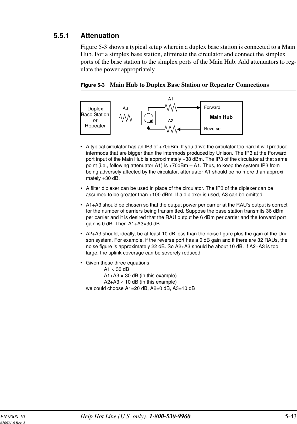
Contents
- 1. User Manual 1 of 2
- 2. User Manual 2 of 2
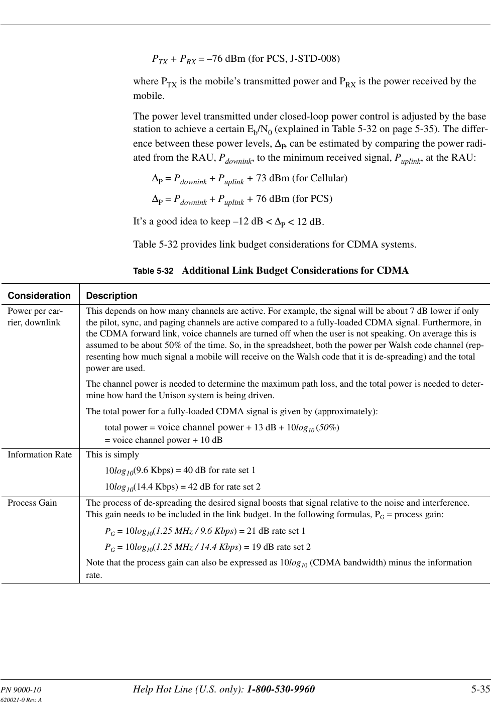
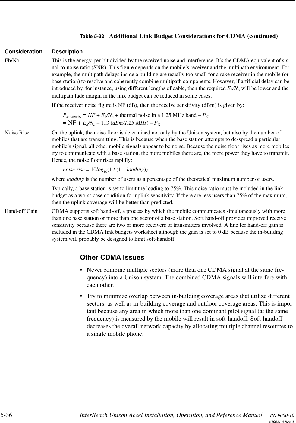
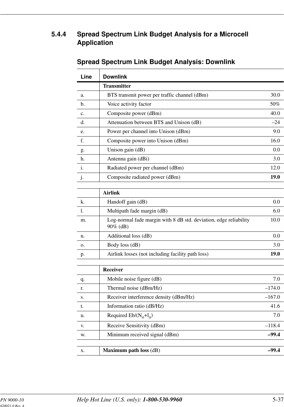
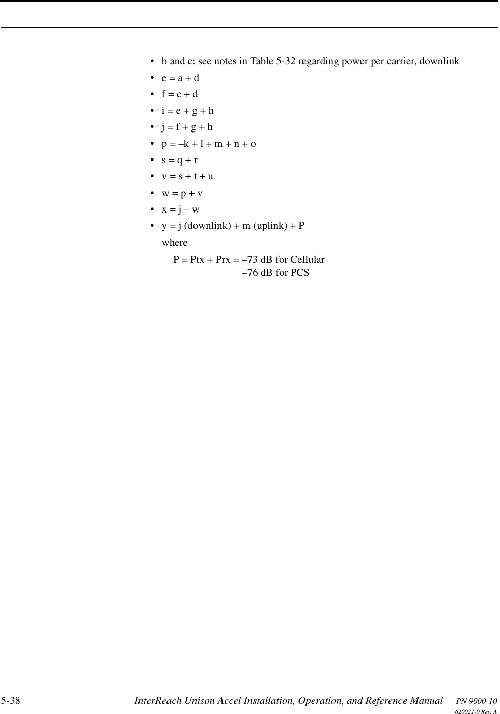
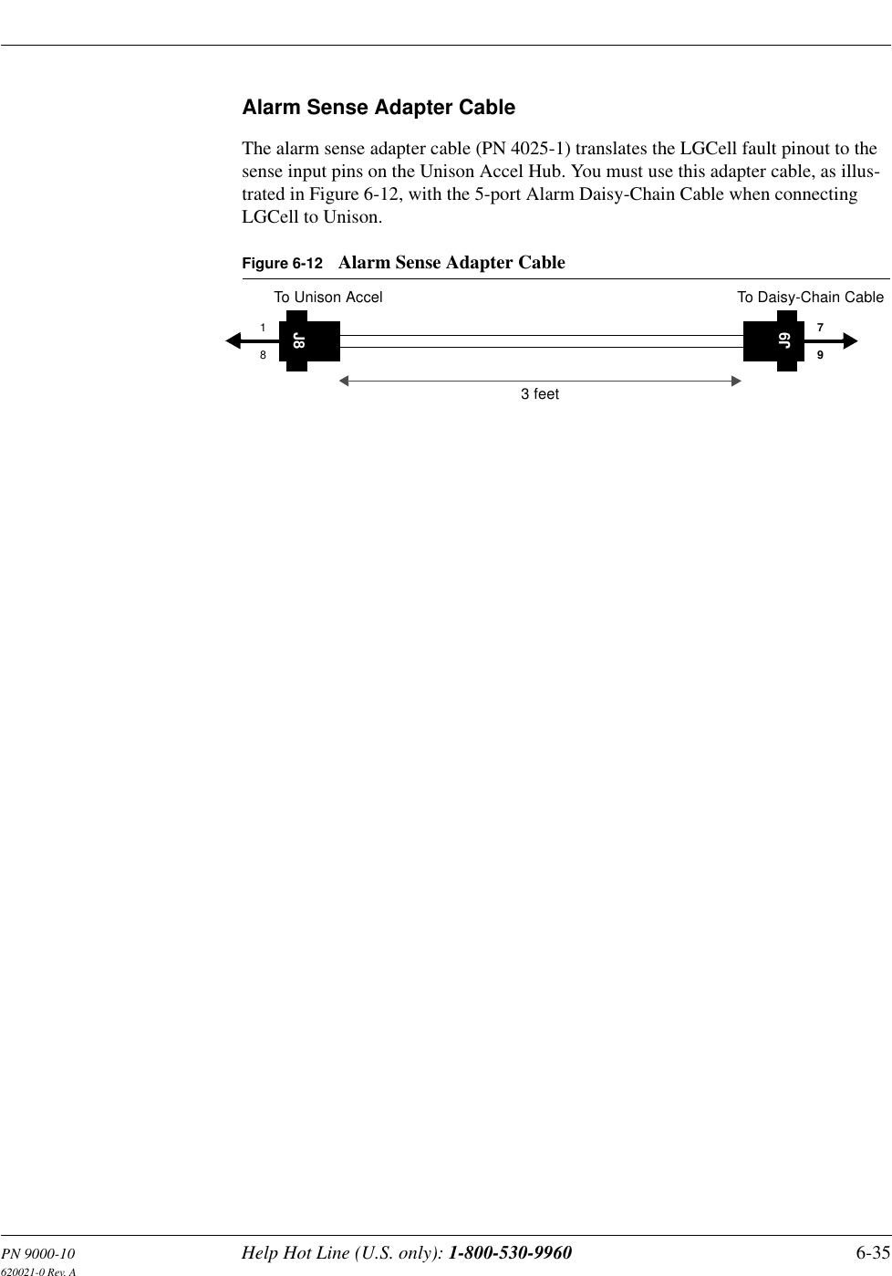
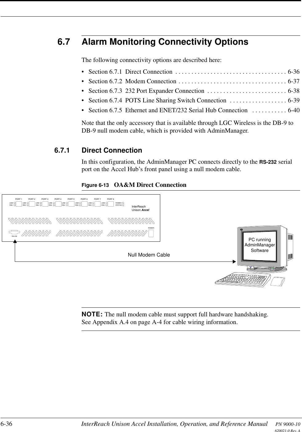
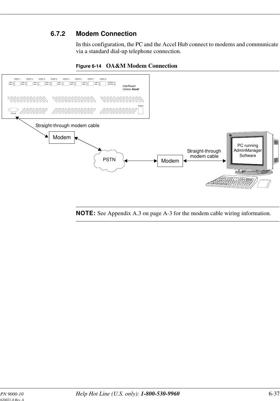
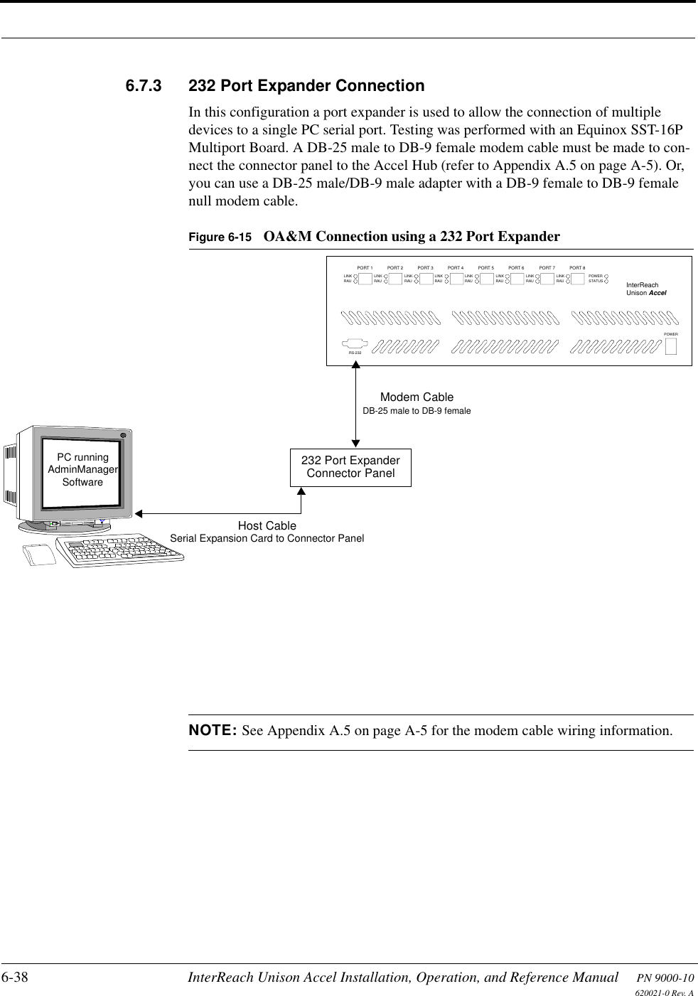
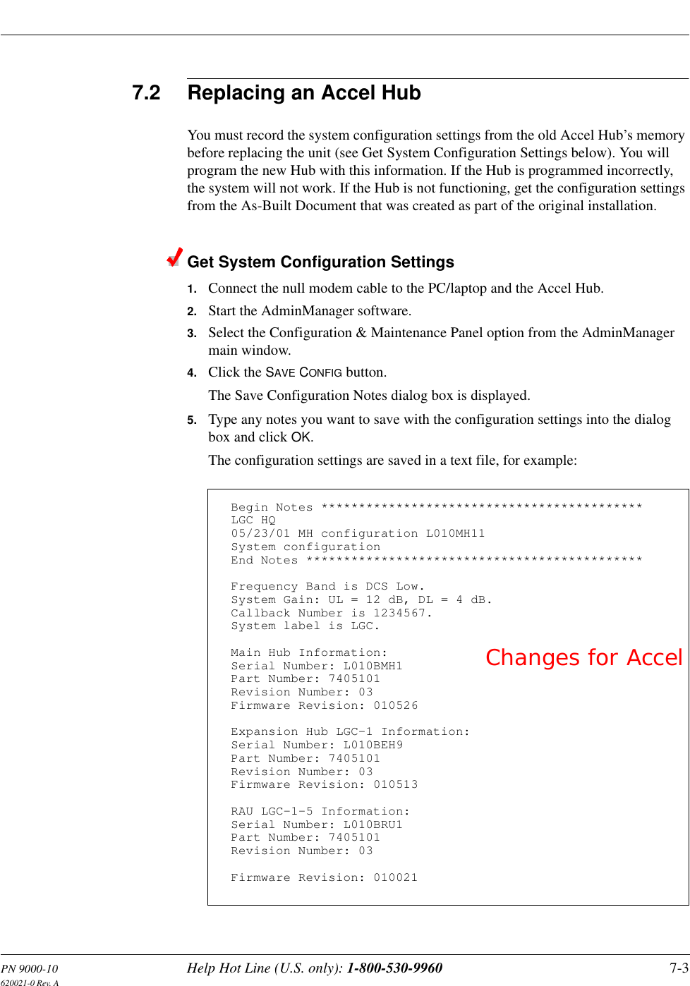
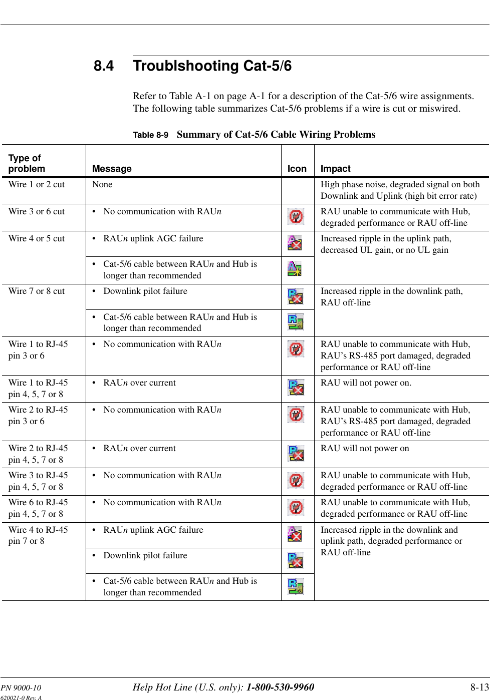
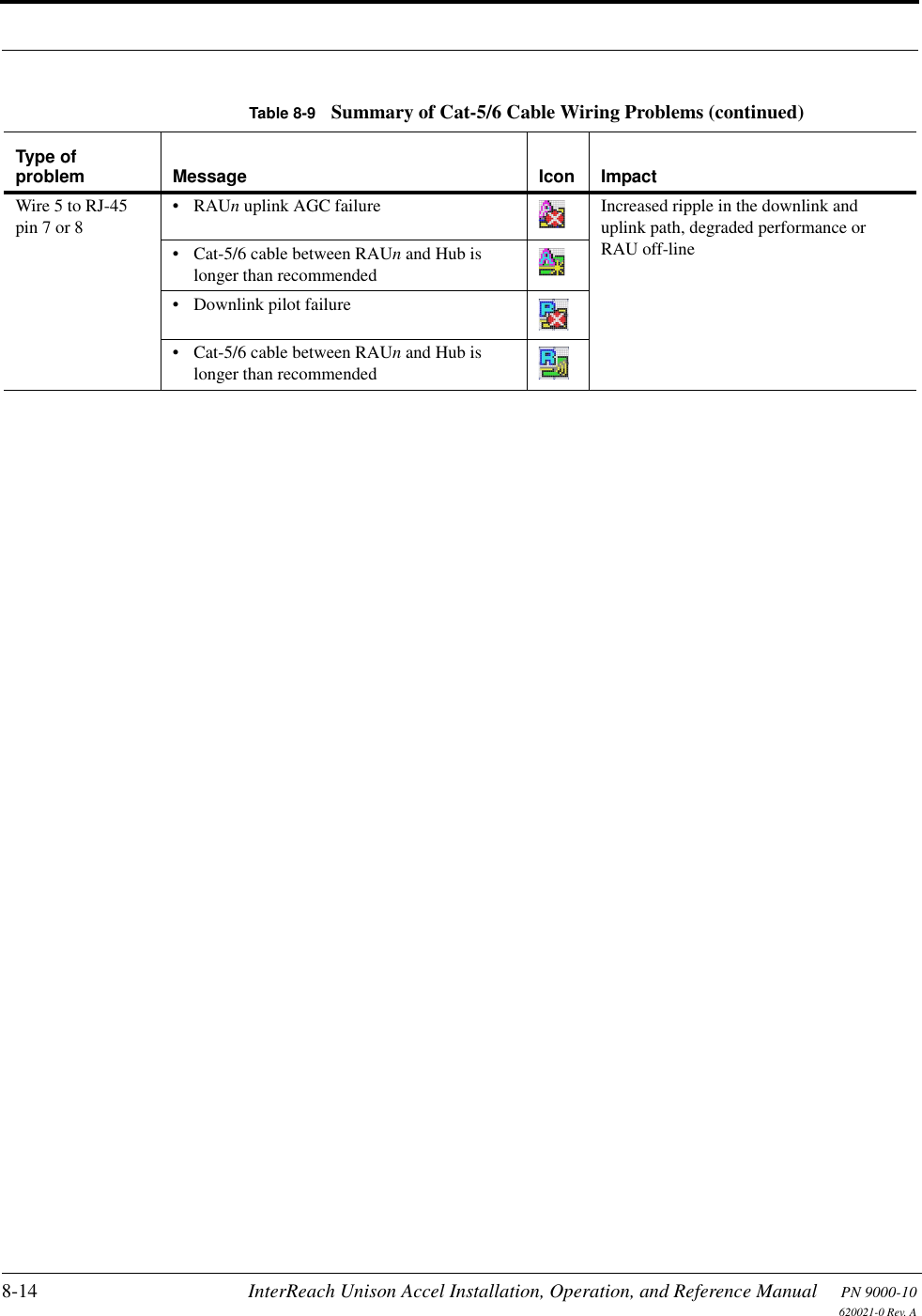
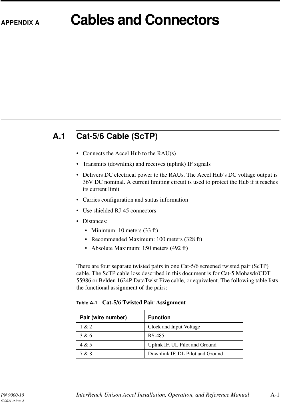
User Manual 2 of 2