ADC Telecommunications UNS-EGSM-2 900MHz EGSM In-Building Distributed Antenna System User Manual accel
ADC Telecommunications Inc. 900MHz EGSM In-Building Distributed Antenna System accel
Contents
- 1. User Manual 1 of 2
- 2. User Manual 2 of 2
User Manual 2 of 2

PN 9000-10 Help Hot Line (U.S. only): 1-800-530-9960 5-31
620021-0 Rev. A
Thermal Noise This is the noise level in the signal bandwidth (BW).
Thermal noise power = –174 dBm/Hz + 10Log(BW).
Required C/I ratio For each wireless standard a certain C/I (carrier to interference) ratio is needed to obtain acceptable
demodulation performance. For narrowband systems, (TDMA, GSM, EDGE, iDEN, AMPS) this
level varies from about 9 dB to 20 dB.
Mobile Transmit
Power
The maximum power the mobile can transmit (power transmitted at highest power level setting).
Multipath Fade
Margin
This margin allows for a certain level of fading due to multipath interference. Inside buildings there
is often one or more fairly strong signals and many weaker signals arriving from reflections and dif-
fraction. Signals arriving from multiple paths add constructively or destructively. This margin
accounts for the possibility of destructive multipath interference. In RF site surveys this margin will
not appear because it will be averaged out over power level samples taken over many locations.
Log-normal Fade
Margin
This margin adds an allowance for RF shadowing due to objects obstructing the direct path between
the mobile equipment and the RAU. In RF site surveys, this shadowing will not appear because it
will be averaged out over power level samples taken over many locations.
Body Loss This accounts for RF attenuation caused by the user’s head and body.
Minimum Received
Signal Level
This is also referred to as the “design goal”. The link budget says that you can achieve adequate cov-
erage if the signal level is, on average, above this level over 95% of the area covered, for example.
Table 5-30 Link Budget Considerations for Narrowband Systems (continued)
Consideration Description
Protocol Signal
Bandwidth Thermal
Noise
TDMA 30 kHz –129 dBm
GSM 200 kHz –121 dBm
iDEN 25 kHz –130 dBm

5-32 InterReach Unison Accel Installation, Operation, and Reference Manual PN 9000-10
620021-0 Rev. A
5.4.2 Narrowband Link Budget Analysis for a Microcell Application
Narrowband Link Budget Analysis: Downlink
• c = a + b
• f = c + d + e
• j = g + h + i
• n = k + l + m
• k: in this example, k represents the thermal noise for a TDMA signal, which
has a bandwidth of 30 kHz
•p = f – j – n
Line Downlink
Transmitter
a. BTS transmit power per carrier (dBm) 33
b. Attenuation between BTS and Unison (dB) –23
c. Power into Unison (dBm) 10
d. Unison gain (dB) 0
e. Antenna gain (dBi) 3
f. Radiated power per carrier (dBm) 13
Airlink
g. Multipath fade margin (dB) 6
h. Log-normal fade margin with 8 dB std. deviation, edge reliability 90%
(dB)
11
i. Body loss (dB) 3
j. Airlink losses (not including facility path loss) 20
Receiver
k. Thermal noise (dBm/30 kHz) –129
l. Mobile noise figure (dB) 7
m. Required C/I ratio (dB) 17
n. Minimum received signal (dBm) –105
p. Maximum path loss (dB) –98

PN 9000-10 Help Hot Line (U.S. only): 1-800-530-9960 5-33
620021-0 Rev. A
Narrowband Link Budget Analysis: Uplink
• e: enter the noise figure and gain of each system component (a, b, c, and d) into
the standard cascaded noise figure formula
• i = f + e + g – h
• m = j + k + l
• p = n – m – i
Therefore, the system is downlink limited but the downlink and uplink are almost
balanced, which is a desirable condition.
Line Uplink
Receiver
a. BTS noise figure (dB) 4
b. Attenuation between BTS and Unison (dB) –10
c. Unison gain (dB) 0
d. Unison noise figure (dB) 1-4-32 22
e. System noise figure (dB) 22.6
f. Thermal noise (dBm/30 kHz) –129
g. Required C/I ratio (dB) 12
h. Antenna gain (dBi) 3
i. Receive sensitivity (dBm) –97.4
Airlink
j. Multipath fade margin (dB) 6
k. Log-normal fade margin with 8 dB std. deviation, edge reliability 90%
(dB)
10
l. Body loss (dB) 3
m. Airlink losses (not including facility path loss) 19
Transmitter
n. Mobile transmit power (dBm) 28
p. Maximum path loss (dB) 106.4
Fsys = F1 + + + ....
F2 – 1
G1
F3 – 1
G1G2
where
F = 10
(See Rappaport, Theodore S. Wireless Communications, Principles, and Practice. Prentice Hall PTR, 1996.)
(Noise Figure/10)
G = 10(Gain/10)

5-34 InterReach Unison Accel Installation, Operation, and Reference Manual PN 9000-10
620021-0 Rev. A
5.4.3 Elements of a Link Budget for CDMA Standards
A CDMA link budget is slightly more complicated because the spread spectrum
nature of CDMA must be considered. Unlike narrowband standards such as TDMA
and GSM, CDMA signals are spread over a relatively wide frequency band. Upon
reception, the CDMA signal is de-spread. In the de-spreading process the power in
the received signal becomes concentrated into a narrow band, whereas the noise level
remains unchanged. Hence, the signal-to-noise ratio of the de-spread signal is higher
than that of the CDMA signal before de-spreading. This increase is called processing
gain. For IS-95 and J-STD-008, the processing gain is 21 dB or 19 dB depending on
the user data rate (9.6 Kbps for rate set 1 and 14.4 Kbps for rate set 2, respectively).
Because of the processing gain, a CDMA signal (comprising one Walsh code channel
within the composite CDMA signal) can be received at a lower level than that
required for narrowband signals. A reasonable level is –95 dBm, which results in
about –85 dBm composite as shown below.
An important issue to keep in mind is that the downlink CDMA signal is composed of
many orthogonal channels: pilot, paging, sync, and traffic. The composite power
level is the sum of the powers from the individual channels. An example is given in
the following table.
This table assumes that there are 15 active traffic channels operating with 50% voice
activity (so that the total power adds up to 100%). Notice that the pilot and sync chan-
nels together contribute about 25% of the power. When measuring the power in a
CDMA signal you must be aware that if only the pilot and sync channels are active,
the power level will be about 6 to 7 dB lower than the maximum power level you can
expect when all voice channels are active. The implication is that if only the pilot and
sync channels are active, and the maximum power per carrier table says that you
should not exceed 10 dBm for a CDMA signal, for example, then you should set the
attenuation between the base station and the Main Hub so that the Main Hub receives
3 dBm (assuming 0 dB system gain).
An additional consideration for CDMA systems is that the uplink and downlink paths
should be gain and noise balanced. This is required for proper operation of soft-hand-
off to the outdoor network as well as preventing excess interference that is caused by
mobiles on the indoor system transmitting at power levels that are not coordinated
with the outdoor mobiles. This balance is achieved if the power level transmitted by
the mobiles under close-loop power control is similar to the power level transmitted
under open-loop power control. The open-loop power control equation is
PTX + PRX = –73 dBm (for Cellular, IS-95)
Table 5-31 Distribution of Power within a CDMA Signal
Channel Walsh Code Number Relative Power Level
Pilot 0 20% –7.0 dB
Sync 32 5% –13.3 dB
Primary Paging 1 19% –7.3 dB
Traffic 8–31, 33–63 9% (per traffic channel) –10.3 dB

PN 9000-10 Help Hot Line (U.S. only): 1-800-530-9960 5-35
620021-0 Rev. A
PTX + PRX = –76 dBm (for PCS, J-STD-008)
where PTX is the mobile’s transmitted power and PRX is the power received by the
mobile.
The power level transmitted under closed-loop power control is adjusted by the base
station to achieve a certain Eb/N0 (explained in Table 5-32 on page 5-35). The differ-
ence between these power levels, ∆P
, can be estimated by comparing the power radi-
ated from the RAU, Pdownink, to the minimum received signal, Puplink, at the RAU:
∆P = Pdownink + Puplink + 73 dBm (for Cellular)
∆P = Pdownink + Puplink + 76 dBm (for PCS)
It’s a good idea to keep –12 dB < ∆P < 12 dB.
Table 5-32 provides link budget considerations for CDMA systems.
Table 5-32 Additional Link Budget Considerations for CDMA
Consideration Description
Power per car-
rier, downlink
This depends on how many channels are active. For example, the signal will be about 7 dB lower if only
the pilot, sync, and paging channels are active compared to a fully-loaded CDMA signal. Furthermore, in
the CDMA forward link, voice channels are turned off when the user is not speaking. On average this is
assumed to be about 50% of the time. So, in the spreadsheet, both the power per Walsh code channel (rep-
resenting how much signal a mobile will receive on the Walsh code that it is de-spreading) and the total
power are used.
The channel power is needed to determine the maximum path loss, and the total power is needed to deter-
mine how hard the Unison system is being driven.
The total power for a fully-loaded CDMA signal is given by (approximately):
total power = voice channel power + 13 dB + 10log10 (50%)
= voice channel power + 10 dB
Information Rate This is simply
10log10(9.6 Kbps) = 40 dB for rate set 1
10log10(14.4 Kbps) = 42 dB for rate set 2
Process Gain The process of de-spreading the desired signal boosts that signal relative to the noise and interference.
This gain needs to be included in the link budget. In the following formulas, PG = process gain:
PG = 10log10(1.25 MHz / 9.6 Kbps) = 21 dB rate set 1
PG = 10log10(1.25 MHz / 14.4 Kbps) = 19 dB rate set 2
Note that the process gain can also be expressed as 10log10 (CDMA bandwidth) minus the information
rate.

5-36 InterReach Unison Accel Installation, Operation, and Reference Manual PN 9000-10
620021-0 Rev. A
Other CDMA Issues
• Never combine multiple sectors (more than one CDMA signal at the same fre-
quency) into a Unison system. The combined CDMA signals will interfere with
each other.
• Try to minimize overlap between in-building coverage areas that utilize different
sectors, as well as in-building coverage and outdoor coverage areas. This is impor-
tant because any area in which more than one dominant pilot signal (at the same
frequency) is measured by the mobile will result in soft-handoff. Soft-handoff
decreases the overall network capacity by allocating multiple channel resources to
a single mobile phone.
Eb/No This is the energy-per-bit divided by the received noise and interference. It’s the CDMA equivalent of sig-
nal-to-noise ratio (SNR). This figure depends on the mobile’s receiver and the multipath environment. For
example, the multipath delays inside a building are usually too small for a rake receiver in the mobile (or
base station) to resolve and coherently combine multipath components. However, if artificial delay can be
introduced by, for instance, using different lengths of cable, then the required Eb/No will be lower and the
multipath fade margin in the link budget can be reduced in some cases.
If the receiver noise figure is NF (dB), then the receive sensitivity (dBm) is given by:
Psensitivity = NF + Eb/No + thermal noise in a 1.25 MHz band – PG
= NF + Eb/No – 113 (dBm/1.25 MHz) – PG
Noise Rise On the uplink, the noise floor is determined not only by the Unison system, but also by the number of
mobiles that are transmitting. This is because when the base station attempts to de-spread a particular
mobile’s signal, all other mobile signals appear to be noise. Because the noise floor rises as more mobiles
try to communicate with a base station, the more mobiles there are, the more power they have to transmit.
Hence, the noise floor rises rapidly:
noise rise = 10log10(1 / (1 – loading))
where loading is the number of users as a percentage of the theoretical maximum number of users.
Typically, a base station is set to limit the loading to 75%. This noise ratio must be included in the link
budget as a worst-case condition for uplink sensitivity. If there are less users than 75% of the maximum,
then the uplink coverage will be better than predicted.
Hand-off Gain CDMA supports soft hand-off, a process by which the mobile communicates simultaneously with more
than one base station or more than one sector of a base station. Soft hand-off provides improved receive
sensitivity because there are two or more receivers or transmitters involved. A line for hand-off gain is
included in the CDMA link budgets worksheet although the gain is set to 0 dB because the in-building
system will probably be designed to limit soft-handoff.
Table 5-32 Additional Link Budget Considerations for CDMA (continued)
Consideration Description

PN 9000-10 Help Hot Line (U.S. only): 1-800-530-9960 5-37
620021-0 Rev. A
5.4.4 Spread Spectrum Link Budget Analysis for a Microcell
Application
Spread Spectrum Link Budget Analysis: Downlink
Line Downlink
Transmitter
a. BTS transmit power per traffic channel (dBm) 30.0
b. Voice activity factor 50%
c. Composite power (dBm) 40.0
d. Attenuation between BTS and Unison (dB) –24
e. Power per channel into Unison (dBm) 9.0
f. Composite power into Unison (dBm) 16.0
g. Unison gain (dB) 0.0
h. Antenna gain (dBi) 3.0
i. Radiated power per channel (dBm) 12.0
j. Composite radiated power (dBm) 19.0
Airlink
k. Handoff gain (dB) 0.0
l. Multipath fade margin (dB) 6.0
m. Log-normal fade margin with 8 dB std. deviation, edge reliability
90% (dB)
10.0
n. Additional loss (dB) 0.0
o. Body loss (dB) 3.0
p. Airlink losses (not including facility path loss) 19.0
Receiver
q. Mobile noise figure (dB) 7.0
r. Thermal noise (dBm/Hz) –174.0
s. Receiver interference density (dBm/Hz) –167.0
t. Information ratio (dB/Hz) 41.6
u. Required Eb/(No+lo)7.0
v. Receive Sensitivity (dBm) –118.4
w. Minimum received signal (dBm) –99.4
x. Maximum path loss (dB) –99.4

5-38 InterReach Unison Accel Installation, Operation, and Reference Manual PN 9000-10
620021-0 Rev. A
• b and c: see notes in Table 5-32 regarding power per carrier, downlink
• e = a + d
• f = c + d
• i = e + g + h
• j = f + g + h
• p = –k + l + m + n + o
• s = q + r
• v = s + t + u
• w = p + v
•x = j – w
• y = j (downlink) + m (uplink) + P
where
P = Ptx + Prx = –73 dB for Cellular
–76 dB for PCS

PN 9000-10 Help Hot Line (U.S. only): 1-800-530-9960 5-39
620021-0 Rev. A
Spread Spectrum Link Budget Analysis: Uplink
Line Uplink
Receiver
a. BTS noise figure (dB) 3.0
b. Attenuation between BTS and Unison (dB) –30.0
c. Unison gain (dB) 0.0
d. Unison noise figure (dB) 22.0
e. System noise figure (dB) 33.3
f. Thermal noise (dBm/Hz) –174.0
g. Noise rise 75% loading (dB) 6.0
h. Receiver interference density (dBm/Hz) –134.6
i. Information rate (dB/Hz) 41.6
j. Required Eb/(No+lo)5.0
k. Handoff gain (dB) 0.0
l. Antenna gain (dBi) 3.0
m. Minimum received signal (dBm) –91.1
Airlink
n. Multipath fade margin (dB) 6.0
o. Log-normal fade margin with 8 dB std. deviation, edge reliability
90% (dB)
10.0
p. Additional loss (dB) 0.0
q. Body loss (dB) 3.0
r. Airlink losses (not including facility path loss) 19.0
Transmitter
s. Mobile transmit power (dBm) 28.0
t. Maximum path loss (dB) 100.1

5-40 InterReach Unison Accel Installation, Operation, and Reference Manual PN 9000-10
620021-0 Rev. A
• e: enter the noise figure and gain of each system component (a, b, c, and d) into
the standard cascaded noise figure formula
• h = e + f + g
• m = h + i + j –k – l
• r = n + o + p + q
• t = s – r – m
Fsys = F1 + + + ....
F2 – 1
G1
F3 – 1
G1G2
where
F = 10
(See Rappaport, Theodore S. Wireless Communications, Principles, and Practice. Prentice Hall PTR, 1996.)
(Noise Figure/10)
G = 10(Gain/10)

PN 9000-10 Help Hot Line (U.S. only): 1-800-530-9960 5-41
620021-0 Rev. A
5.4.5 Considerations for Re-Radiation (over-the-air) Systems
Unison can be used to extend the coverage of the outdoor network by connecting to a
roof-top donor antenna that is pointed toward an outdoor base station. Additional
considerations for such an application of Unison are:
• Sizing the gain and output power requirements for a bi-directional amplifier
(repeater).
• Ensuring that noise radiated on the uplink from the in-building system does not
cause the outdoor base station to become desensitized to wireless handsets in the
outdoor network.
• Filtering out signals that lie in adjacent frequency bands. For instance, if you are
providing coverage for Cellular B-band operation it may be necessary to filter out
the A, A’ and A” bands which may contain strong signals from other outdoor base
stations.
Further information on these issues can be found in LGC Wireless’ application notes
for re-radiation applications.
5-42 InterReach Unison Accel Installation, Operation, and Reference Manual PN 9000-10
620021-0 Rev. A
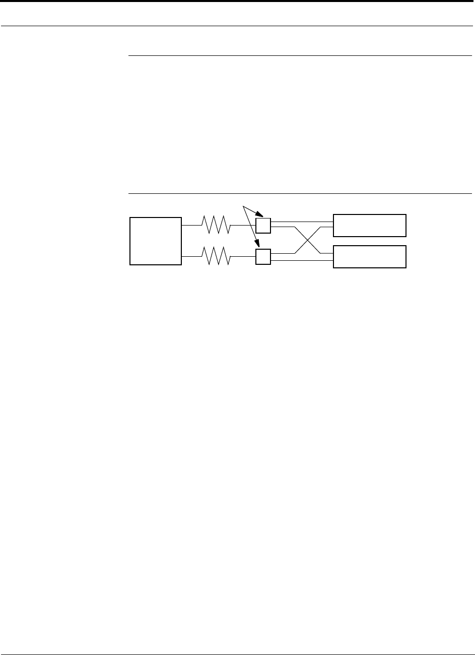
5.5 Connecting a Main Hub to a Base Station
The first consideration when connecting Unison Main Hubs to a base station is to
ensure there is an equal amount of loss through cables, combiners, etc. from the base
station to the Main Hubs. For this example, assume that the base station will have
simplex connections, one uplink and one downlink. Each of these connections will
need to be divided to equilibrate power for each Main Hub. For example, two Main
Hubs will require a 2×1 combiner/divider; four Main Hubs will require a 4×1 com-
biner/divider; and so on.
Figure 5-2 Connecting Main Hubs to a Simplex Base Station
When connecting a Unison Main Hub to a base station, also consider the following:
1. The downlink power from the base station must be attenuated enough so that the
power radiated by the RAU does not exceed the maximum power per carrier listed
in Section 5.1, “Maximum Output Power per Carrier at RAU,” on page 5-3.
2. The uplink attenuation should be small enough that the sensitivity of the overall
system is limited by Unison, not by the attenuator. However, some base stations
will trigger alarms if the noise or signal levels are too high. In this case the attenu-
ation will have to be large enough to prevent this from happening.
If, in an area covered by Unison, a mobile phone indicates good signal strength but
consistently has difficulty completing calls, it is possible that the attenuation between
Unison and the base station needs to be adjusted. In other words, it is possible that if
the uplink is over-attenuated, the downlink power will provide good coverage, but the
uplink coverage distance will be small.
When there is an excessive amount of loss between the Main Hub uplink and the base
station, the uplink system gain can be increased to as much as 15 dB to prevent a
reduction in the overall system sensitivity.
Base Station
2 × 1 combiner/divider
Downlink/Forward
Main Hub 1
Main Hub 2
Uplink/Reverse
PN 9000-10 Help Hot Line (U.S. only): 1-800-530-9960 5-43
620021-0 Rev. A
5.5.1 Attenuation
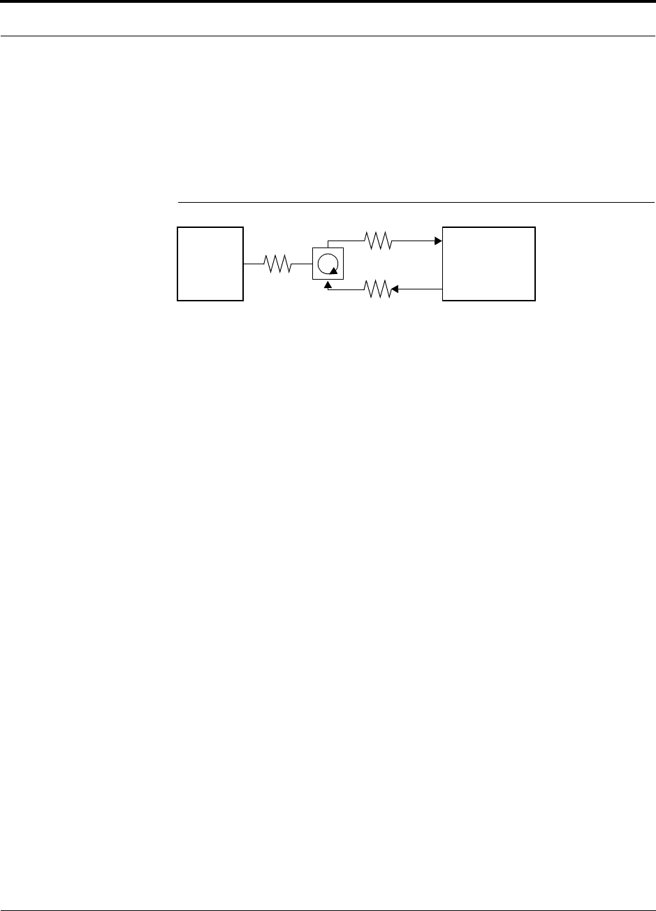
Figure 5-3 shows a typical setup wherein a duplex base station is connected to a Main
Hub. For a simplex base station, eliminate the circulator and connect the simplex
ports of the base station to the simplex ports of the Main Hub. Add attenuators to reg-
ulate the power appropriately.
Figure 5-3 Main Hub to Duplex Base Station or Repeater Connections
Duplex
Base Station Main Hub
Forward
Reverse
A3
A1
A2
• A typical circulator has an IP3 of +70dBm. If you drive the circulator too hard it will produce
intermods that are bigger than the intermods produced by Unison. The IP3 at the Forward
port input of the Main Hub is approximately +38 dBm. The IP3 of the circulator at that same
point (i.e., following attenuator A1) is +70dBm – A1. Thus, to keep the system IP3 from
being adversely affected by the circulator, attenuator A1 should be no more than approxi-
mately +30 dB.
• A filter diplexer can be used in place of the circulator. The IP3 of the diplexer can be
assumed to be greater than +100 dBm. If a diplexer is used, A3 can be omitted.
• A1+A3 should be chosen so that the output power per carrier at the RAU’s output is correct
for the number of carriers being transmitted. Suppose the base station transmits 36 dBm
per carrier and it is desired that the RAU output be 6 dBm per carrier and the forward port
gain is 0 dB. Then A1+A3=30 dB.
• A2+A3 should, ideally, be at least 10 dB less than the noise figure plus the gain of the Uni-
son system. For example, if the reverse port has a 0 dB gain and if there are 32 RAUs, the
noise figure is approximately 22 dB. So A2+A3 should be about 10 dB. If A2+A3 is too
large, the uplink coverage can be severely reduced.
• Given these three equations:
A1 < 30 dB
A1+A3 = 30 dB (in this example)
A2+A3 < 10 dB (in this example)
we could choose A1=20 dB, A2=0 dB, A3=10 dB
or
Repeater

5-44 InterReach Unison Accel Installation, Operation, and Reference Manual PN 9000-10
620021-0 Rev. A
5.5.2 Uplink Attenuation
The attenuation between the Main Hub’s uplink port and the base station does two
things:
1. It attenuates the noise coming out of Unison.
2. It attenuates the desired signals coming out of Unison.
Setting the attenuation on the uplink is a trade-off between keeping the noise and
maximum signal levels transmitted from Unison to the base station receiver low
while not reducing the SNR (signal-to-noise ratio) of the path from the RAU inputs to
the base station inputs. This SNR can not be better than the SNR of Unison by itself,
although it can be significantly worse.
For example, suppose we have a GSM Unison system consisting of one Hub and 8
RAUs (1-8) with uplink NF=22 dB. (See Table 5-32 on page 5-35.) If we use 30 dB
of attenuation between the Main Hub’s uplink port and the base station (which has its
own noise figure of about 4 dB), the overall noise figure will be 34.3 dB (refer to the
formula on page 5-33) which is 12.3 dB worse than Unison by itself. That causes a
12.3 dB reduction in the uplink coverage distance. Now, if the attenuation instead is
10 dB, the cascaded noise figure is NF=22.6 dB, which implies that the uplink sensi-
tivity is limited by Unison, a desirable condition.
Rule of Thumb
A good rule of thumb is to set the uplink attenuation, A2+A3 in Figure 5-3 on
page 5-43, as follows:
A2+A3 ≈ Unison uplink NF + uplink gain (0 dB for reverse port) – BTS NF – 10dB
and round A2 down to the nearest convenient attenuation value.

PN 9000-10 Help Hot Line (U.S. only): 1-800-530-9960 5-45
620021-0 Rev. A
5.5.2.1 Uplink Attenuation Exception: CDMA
In CDMA systems, the power transmitted by the mobile is determined by the charac-
teristics of both the uplink and downlink paths. The power transmitted by the mobile
should be similar in open-loop control (as determined by the downlink path) as dur-
ing closed-loop control (as determined by the uplink and downlink paths). In addi-
tion, the mobile’s transmit power when it communicates with a base station through
Unison should be similar to the power transmitted when it communicates with a base
station in the outdoor network (during soft hand-off). Because of these consider-
ations, you should not allow the downlink and uplink gains to vary widely.
Open-loop power control:
PTX = –76 dBm (for PCS) – PRX
where PTX is the power transmitted and PRX is the power received by the mobile. If
PL is the path loss (in dB) between the RAU and the mobile, and PDN is the downlink
power radiated by the RAU, then
PTX = –76 dBm (for PCS) – PDN + PL
Closed-loop power control:
PTX = noise floor + uplink NF – process gain + Eb/No + PL
= –113 dBm/1.25 Mhz + NF – 19 dB + 7 dB + PL
where Eb/No = 7 dB is a rough estimate, and NF is the cascaded noise figure of the
Unison uplink, the uplink attenuation, and the base station noise figure. Equating PTX
for the open-loop and closed-loop we see that
NF = 49 – PDN
where PDN is determined by the downlink attenuation. Since PDN for Unison is about
10 dBm, we see that the cascaded noise figure is about 39 dB, which is considerably
higher than that of Unison itself. This implies that we should use a fairly large attenu-
ation on the uplink. This case suggests using as much attenuation on the downlink as
on the uplink. The drawback of doing this is that the uplink coverage sensitivity is
reduced. A link budget analysis will clarify these issues. Typically, the uplink attenu-
ation between the Main Hub and the base station will be the same as, or maybe 10 dB
less than, the downlink attenuation.

5-46 InterReach Unison Accel Installation, Operation, and Reference Manual PN 9000-10
620021-0 Rev. A
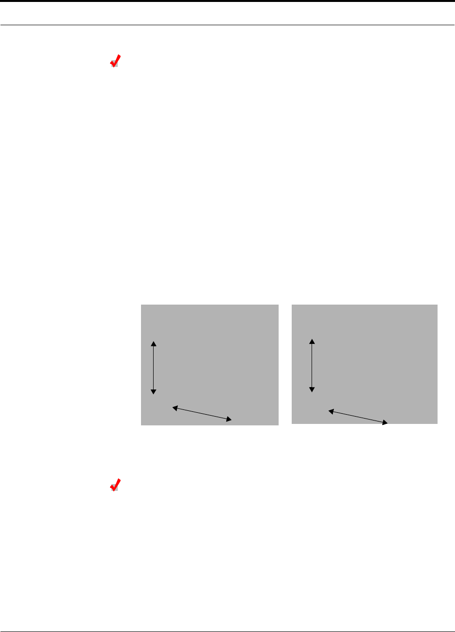
5.6 Designing for a Neutral Host System
Designing for a neutral host system uses the same design rules previously discussed.
Since a neutral host system typically uses multiple systems in parallel with common
equipment locations, we find it best to design according to the minimum among the
systems’ RAU coverage distances so that there will not be holes in the coverage area,
and so that the economies of a single installation can be achieved. For example, as
indicated in Section 7.1, the 1900 MHz RF signals do not propagate throughout a
building as well as the 800 MHz signals. Therefore, we design using the 1900 MHz
radiated distance, calculated with the path loss slope formula.
The example neutral host system described below consists of one iDEN, one 800
MHz, and two 1900 MHz systems and can support up to seven separate service pro-
viders in the following manner:
•1 on iDEN
• 2 on 800 MHz, A band and B band
• 2 in each of the two 1900 MHz frequency sub-bands
Example Unison Neutral Host System
The following example configuration was designed to provide:
• Similar coverage per band in an office environment that is 80% cubicles and
20% offices.
• Similar capacity.
• Support for up to 7 Operators, where equipment has been shared to minimize
the number of parallel systems.
Example Configuration:
• 800 MHz iDEN: 16 channels (3 dBm)
• 800 MHz Cellular (3 dBm)
TDMA Band: 14 channels (shared)
CDMA Band: 3 channels (shared)
• 1900 MHz PCS (6 dBm)
TDMA Band: 14 channels
CDMA Band: 3 channels (shared)
GSM Band: 6 channels (shared)

PN 9000-10 Help Hot Line (U.S. only): 1-800-530-9960 5-47
620021-0 Rev. A
Similar coverage is achieved by setting the transmit power per carrier of the 800 MHz
systems to 3 dBm per carrier and those of the 1900 MHz systems to 6 dBm per car-
rier.
The numbers of RF carriers were selected in order to match subscriber capacity
approximately. Because each protocol in the example supports a different number of
voice channels, the RF carrier numbers also differ. As the following table indicates,
the 800 MHz Cellular and shared 1900 MHz systems can support additional RF carri-
ers without decreasing the power per carrier figures.
For logistical reasons, Operators involved in a neutral host system sometimes prefer
not to share equipment with other Operators. From technical and economic perspec-
tives, too, this can be a prudent practice in medium to high-capacity installations.
Though deploying parallel systems appears to increase the amount of equipment
needed as well as the system cost, the trade-off between capacity and coverage must
be considered because, in short, as capacity increases, coverage area per RAU
decreases. Therefore, more RAUs (and perhaps Hubs) are needed to cover a given
floor space.
5-48 InterReach Unison Accel Installation, Operation, and Reference Manual PN 9000-10
620021-0 Rev. A
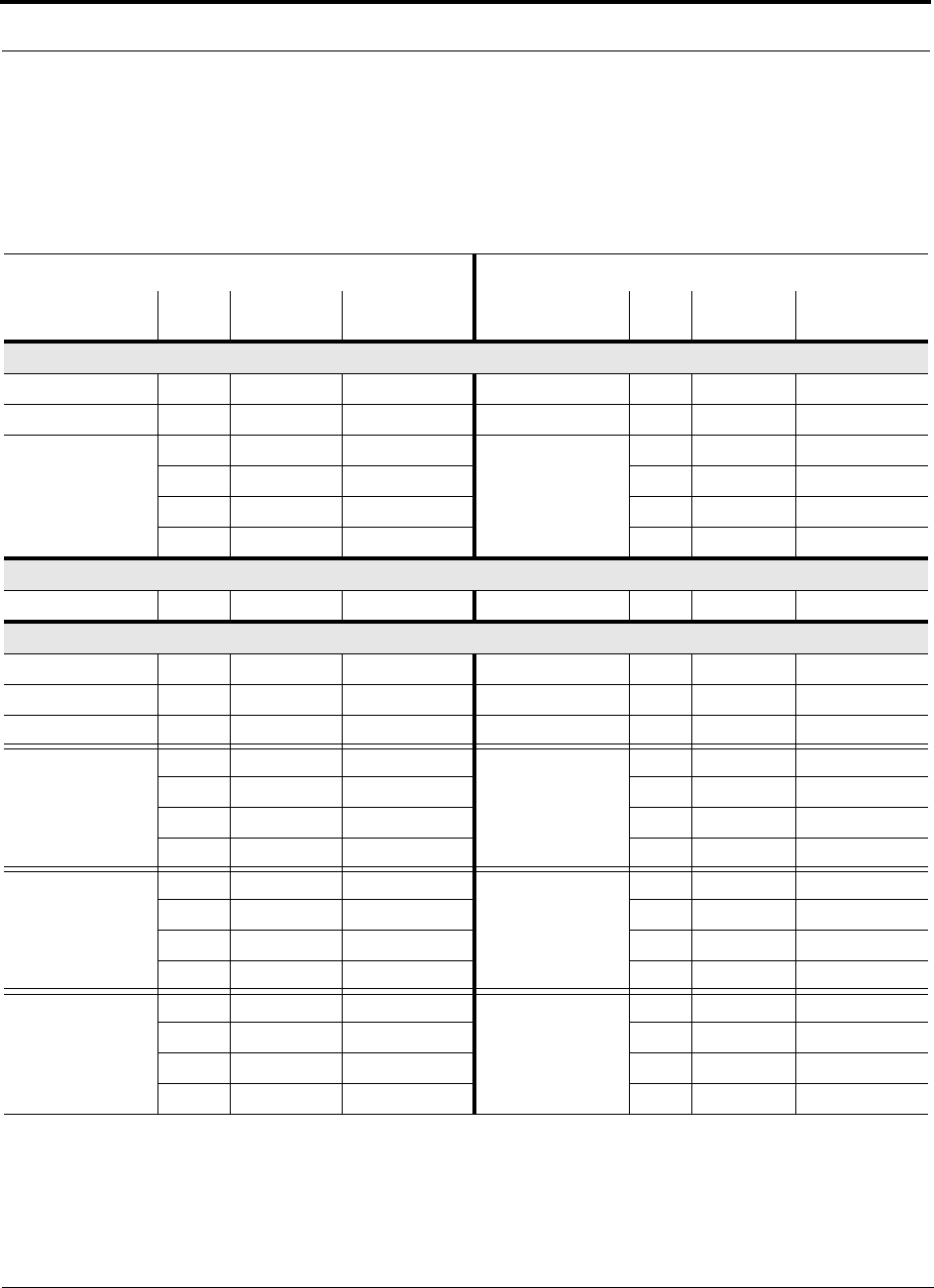
The following table shows the capacities of both 800 and 1900 MHz Unison systems
used for single and multiple protocol applications. The power per carrier for each sys-
tem is based on providing equal coverage areas for both systems when they are used
in an office building that is 80% cubicles and 20% offices.
Note 1
The RF channel capacity limits are based on the Unison data sheets’ “typical” specifications for Cat-5 length and RF performance.
Note 2
The subscriber capacity limits are based on the Erlang B traffic model with a 2% GOS. Each user has a 50mErlangs, which is higher than
the standard 35mErlangs.
Table 1 Unison Capacity: Equal Coverage Areas
Operator #1 Operator #2
Protocol RF
Chs Voice Chs Subscribers Protocol RF
Chs Voice Chs Subscribers
800 MHz Cellular A/B (Unison); 3 dBm power per carrier
TDMA only 35 104 1837 N/A —— —
CDMA only 12 180–240 3327–4517 N/A —— —
TDMA
(combining with CDMA:
Operator #2)
15 44 694 CDMA
(combining with TDMA:
Operator #1)
10 150–200 2736–3723
20 59 974 7 105–140 1856–2540
25 74 1259 4 60–80 993–1374
28 83 1431 2 30–40 439–620
800 MHz iDEN (Unison); 3 dBm power per carrier
iDEN only 16 47 749 N/A —— —
1900 MHz PCS (Unison); 6 dBm power per carrier
TDMA only 14 41 638 N/A —— —
CDMA only 10 150–200 2736–3723 N/A —— —
GSM only 14 111 1973 N/A —— —
TDMA
(combining with CDMA:
Operator #2)
617 213 CDMA
(combining with TDMA:
Operator #1)
4 60–80 993–1374
8 23 315 3 45–60 712–993
10 29 421 2 30–40 439–620
11 32 474 1 15–20 180–264
TDMA
(combining with GSM:
Operator #2)
617 213 GSM
(combining with TDMA:
Operator #1)
755 899
8 23 315 5 39 602
10 29 421 3 23 315
11 32 474 2 15 180
CDMA
(combining with GSM:
Operator #2)
2 30–40 439–620 GSM
(combining with CDMA:
Operator #1)
10 79 1355
4 60–80 993–1374 7 55 899
6 90–120 1566–2148 4 31 457
8 120–200 2148–2933 1 7 59

PN 9000-10 InterReach Unison Accel Installation, Operation, and Reference Manual 6-1
620021-0 Rev. A
SECTION 6 Installing Unison Accel
6.1 Installation Requirements
6.1.1 Component Location Requirements
Unison Accel components are intended to be installed in indoor locations only.
6.1.2 Cable and Connector Requirements
The Accel equipment operates over Category 5 or 6 (Cat-5/6) screened twisted pair
(ScTP) cable with shielded RJ-45 connectors. These cables are widely used industry
standards for Local Area Networks (LANs). The regulations and guidelines for Uni-
son cable installation are identical to those specified by the TIA/EIA 568-A standard
and the TIA/EIA/IS-729 supplement for LANs.
LGC Wireless recommends plenum-rated Cat-5/6 ScTP cable and connectors for
conformity to building codes and standards. Mohawk/CDT 55986 or Belden 1624P
DataTwist® Five ScTP cable, or equivalent is required.
NOTE: In order to meet FCC and CE Mark emissions requirements, the Cat-5/6
cable must be screened (ScTP) and it must be grounded using shielded RJ-45 con-
nectors at both ends.

6-2 InterReach Unison Accel Installation, Operation, and Reference Manual PN 9000-10
620021-0 Rev. A
6.1.3 Multiple Operator System Recommendations
As in any Unison Accel system, a multiple operator (neutral host) system requires
one Cat-5/6 cable between each Accel Hub and each RAU. In situations where Hubs
and/or RAUs will be installed in the future to support the addition of frequency bands
and/or wireless Operators, it is advantageous to install the necessary cabling initially.
Such deployment typically leads to substantial cost savings over installing parallel
cabling at separate times.
6.1.4 Distance Requirements
The following table shows the distances between Unison components and related
equipment.
Table 6-1 Distance Requirements
Equipment
Combination Cable Type Cable Length Additional Information
Repeater to Accel
Hub
Coaxial; N male
connectors
3–6 m (10–20 ft) typical Limited by loss and noise.
Refer to your link budget
calculation.
10 m (33 ft) maximum Limited by CE Mark require-
ments.
Base Station to
Accel Hub
Coaxial; N male
connectors
3–6 m (10–20 ft) typical Limited by loss and noise.
Refer to your link budget
calculation.
10 m (33 ft) maximum Limited by CE Mark require-
ments.
Accel Hub to RAU Cat-5/6 ScTP;
shielded RJ-45 male
connectors
• Minimum: 10 meters (33 ft)
• Recommended Max.: 100 meters (328 ft)
• Absolute Max.: 150 meters (492 ft)
See Section 6.4.4 if using a Cat-5 Extender
See “System Gain (Loss)
Relative to ScTP Cable
Length” on page 5-28.
RAU to passive
antenna
Coaxial; SMA male
connectors
1–3.5 m (3–12 ft) typical Limited by loss and noise.
Refer to your link budget
calculation.
PN 9000-10 Help Hot Line (U.S. only): 1-800-530-9960 6-3
620021-0 Rev. A
6.2 Safety Precautions
6.2.1 Installation Guidelines
Use the following guidelines when installing LGC Wireless equipment:
1. Provide sufficient airflow and cooling to the equipment to prevent heat build-up
from exceeding the maximum ambient air temperature specification. Do not com-
promise the amount of airflow required for safe operation of the equipment.
2. If you are removing the system, turn it off and remove the power cord first. There
are no user-serviceable parts inside the components.
3. The internal power supplies have internal fuses that are not user replaceable. Con-
sider the worst-case power consumption shown on the product labels when provi-
sioning the equipment’s AC power source and distribution.
6.2.2 General Safety Precautions
The following precautions apply to LGC Wireless products:
• The units have no user-serviceable parts. Faulty or failed units are fully replaceable
through LGC Wireless. Please contact us at:
1-800-530-9960 (U.S. only)
+1-408-952-2400 (International)
+44(0) 1223 597812 (Europe)
• Although modeled after an Ethernet/LAN architecture and connectivity, the units
are not intended to connect to Ethernet data hubs, routers, cards, or other similar
data equipment.
• When you connect a radiating antenna to an RAU, firmly hand-tighten the SMA
female connector – DO NOT over-tighten the connector.
WARNING: To reduce the risk of fire or electric shock, do not
expose this equipment to rain or moisture. The components are
intended for indoor use only. Do not install the RAU outdoors. Do not
connect an RAU to an antenna that is located outside where it could
be subject to lightning strikes, power crosses, or wind.

6-4 InterReach Unison Accel Installation, Operation, and Reference Manual PN 9000-10
620021-0 Rev. A
6.3 Preparing for System Installation
6.3.1 Pre-Installation Inspection
Follow this procedure before installing Unison Accel equipment:
1. Verify the number of packages received against the packing list.
2. Check all packages for external damage; report any external damage to the ship-
ping carrier. If there is damage, a shipping agent should be present before you
unpack and inspect the contents because damage caused during transit is the
responsibility of the shipping agent.
3. Open and check each package against the packing slip. If any items are missing,
contact LGC Wireless customer service.
4. If damage is discovered at the time of installation, contact the shipping agent.

PN 9000-10 Help Hot Line (U.S. only): 1-800-530-9960 6-5
620021-0 Rev. A
6.3.2 Installation Checklist
Table 6-2 Installation Checklist
Installation Requirement Consideration
Floor Plans Installation location of equipment clearly marked
System Design Used to verify frequency bands after installation
Power available:
Accel Hub (AC)
To RAU (DC)
Power cord is 2 m (6.5 ft) long.
115/230V, 5.5/3A, 50–60 Hz
36V (from the Hub)
Rack space available 133.5 mm (5.25 in.) high (3U)
Clearance for air circulation:
Accel Hub
RAU
76 mm (3 in.) front and rear, 51 mm (2 in.) sides
76 mm (3 in.) all around
Suitable operating environment:
Accel Hub
RAUs
Indoor location only
0° to +45°C (+32° to +113°F)
5% to 95% non-condensing humidity
–25° to +45°C (–13° to +113°F)
5% to 95% non-condensing humidity
Donor Antenna-to-Unison Configuration
Donor Antenna Installed, inspected; N-male to N-male coaxial cable to lightning arrestor/surge
suppressor
Lightning Arrestor or
Surge Suppressor
Installed between roof-top antenna and repeater; N-male to N-male coaxial cable
Repeater Installed between lightning arrestor/surge suppressor and Hub; N-male to
N-male coaxial cable
Attenuator Installed between the circulator and the Hub downlink port to prevent overload.
Optionally, it may be installed between the uplink port and the circulator
Circulator or Duplexer Installed between the repeater and the Hub uplink and downlink ports
Base Station-to-Unison Configuration
Base Station Verify RF power (see tables in Section 5.1 on page 5-3); N-male to N-male
coaxial cable; installed, inspected
Attenuator Attenuation may be required to achieve the desired RF output at the RAU and
the desired uplink noise floor level
Circulator or Duplexer When using a duplex BTS: Installed between the BTS and the Hub uplink and
downlink ports. Not used with a simplex BTS

6-6 InterReach Unison Accel Installation, Operation, and Reference Manual PN 9000-10
620021-0 Rev. A
Connecting LGCell Main Hub(s) to a Unison Main Hub
5-port Alarm Daisy-Chain Cable
(PN 4024-3)
For contact alarm monitoring: connecting 2 to 21 LGCell Main Hubs to a Unison
Accel Hub
If connecting LGCell to Unison Accel, the Alarm Sense Adapter Cable is
required to connect the daisy-chain cable to Unison
Do not combine LGCell Main Hubs with Unison Accel Hubs in the same daisy
chain
Alarm Sense Adapter Cable
(PN 4024-3)
Use with 5-port Alarm Daisy-Chain Cable to connect up to 21 LGCell Main
Hubs to a Unison Accel Hub
Also, use to connect a single LGCell Main Hub to a Unison Accel Hub
Connecting Multiple Unison Accel Hubs Together
5-port Alarm Daisy-Chain Cable
(PN 4024-3)
For contact alarm monitoring of major and minor alarms. Use to feed the alarms
from multiple Unison Accel Hubs into a BTS or MetroReach Focus
Do not combine Unison Accel Hubs with LGCell Main Hubs in the same chain.
Cabling
Coaxial: repeater or base station to
Accel Hub
Coax approved; N-type male connectors
Coaxial: RAU to passive antennas Use low-loss cable; SMA male connector; typical 1 m (3.3 ft) using RG142
coaxial cable
Cat-5/6 ScTP: TIA/EIA 568-A approved; shielded RJ-45 male connectors. ScTP cable must be
screened and it must be grounded at both connector ends
Tie-off cables to avoid damaging the connectors because of cable strain
Accel Hub to RAUs • Minimum: 10 meters (33 ft)
• Recommended Maximum: 100 meters (328 ft)
• Absolute Maximum: 150 meters (492 ft)
Accel Hub to
Cat-5 Extender to RAU
Configuring System
PC/laptop running AdminManager
software
Refer to the AdminManager User Manual (PN 8810-10)
Miscellaneous
Null modem cable Female connectors; Accel Hub to a PC/laptop that is running the AdminManager
software; local connection
Straight-through cable Female/male connectors; Accel Hub to a modem; remote connection
Table 6-2 Installation Checklist (continued)
Installation Requirement Consideration
Minimum Cat-5/6
Cable Length from
Accel Hub to
Extender
Minimum Cat-5/6
Cable Length from
Extender to RAU
Maximum Total Cat-5/6
Cable Length from Accel
Hub to RAU
90 meters
295 feet
20 meters
65 feet
110 to 170 meters
360 to 557 feet

PN 9000-10 Help Hot Line (U.S. only): 1-800-530-9960 6-7
620021-0 Rev. A
6.3.3 Tools and Materials Required
6.3.4 Optional Accessories
Cat-5 Extender Used if Cat-5/6 run(s) exceed 100 meters
Dual-Band Diplexer Used in dual band systems to combine the output of a low-band RAU and a
high-band RAU to a single dual band antenna
Distances
Accel Hub is within 3–6m (10–20
ft) of connecting repeater
If longer distance, determine the loss of the cable used for this connection and
adjust the RF signal into the Accel Hub accordingly. This can be done by read-
justing the power from the base station, or by changing the attenuation value
between the base station/repeater and the Hub
Accel Hub is within 3–6m (10–20
ft) of connecting base station
Table 6-3 Tools and Materials Required for Component Installation
Description
Cable ties
Philips screwdriver
Mounting screws and spring nuts
Compressed air
Screws, anchors (for mounting RAUs)
Drill
Fusion splicing sleeves
Table 6-4 Optional Accessories for Component Installation
Description
Wall-mount equipment rack(s) (PN 4712)
Note that if using this rack with an Accel Hub, the Hub’s mounting bracket must be
moved to the center mounting position.
Cable management (Cable manager: PN 4759; Tie wrap bar: PN 4757)
Teltone Line Sharing Switch (M-394-B-01)
When using a single POTS line with multiple Accel Hub/Modems: Connect up to four
modems to a line sharing switch; can cascade switches to accommodate up to 16
modems per POTS line
Alarm Cables:
5-port Alarm Daisy-Chain Cable (PN 4024-3)
Alarm Sense Adapter Cable (PN 4025-1)
RAU Dust Cover (PN UNS-1RDP-1)
Table 6-2 Installation Checklist (continued)
Installation Requirement Consideration

6-8 InterReach Unison Accel Installation, Operation, and Reference Manual PN 9000-10
620021-0 Rev. A
6.4 Unison Accel Installation Procedures
The following procedures assume that the system is new from the factory and that it
has not been programmed with a band.
If you are replacing components in a pre-installed system with either new units or
units that may already be programmed (i.e., re-using units from another system), refer
to Section 7.
• Installing an Accel Hub . . . . . . . . . . . . . . . . . . . . . . . . . . . . . . . . . . . . . . . . . . 6-10
• Installing an Accel Hub in a Rack . . . . . . . . . . . . . . . . . . . . . . . . . . . . . . . 6-10
• Installing an Optional Cable Manager in the Rack . . . . . . . . . . . . . . . . . . 6-11
• Connecting the AdminManager PC to the Accel Hub . . . . . . . . . . . . . . . . 6-12
• Installing an Accel Hub in a Wall-Mounted Rack . . . . . . . . . . . . . . . . . . . 6-11
• Connecting the ScTP Cables . . . . . . . . . . . . . . . . . . . . . . . . . . . . . . . . . . . 6-13
• Troubleshooting Accel Hub LEDs During Installation . . . . . . . . . . . . . . . 6-14
• Installing RAUs . . . . . . . . . . . . . . . . . . . . . . . . . . . . . . . . . . . . . . . . . . . . . . . . 6-15
• Installing RAUs . . . . . . . . . . . . . . . . . . . . . . . . . . . . . . . . . . . . . . . . . . . . . 6-15
• Installing Passive Antennas . . . . . . . . . . . . . . . . . . . . . . . . . . . . . . . . . . . . 6-15
• Connecting the Antenna to the RAU . . . . . . . . . . . . . . . . . . . . . . . . . . . . . 6-15
• Connecting the ScTP Cable . . . . . . . . . . . . . . . . . . . . . . . . . . . . . . . . . . . . 6-16
• Troubleshooting RAU LEDs During Installation . . . . . . . . . . . . . . . . . . . . 6-16
• Installing RAUs in a Dual Band System . . . . . . . . . . . . . . . . . . . . . . . . . . 6-17
• Connecting the Antenna to the Dual Band Diplexer . . . . . . . . . . . . . . . . . 6-18
• Configuring the System . . . . . . . . . . . . . . . . . . . . . . . . . . . . . . . . . . . . . . . . . . 6-20
• Configuring the Installed System . . . . . . . . . . . . . . . . . . . . . . . . . . . . . . . . 6-20

PN 9000-10 Help Hot Line (U.S. only): 1-800-530-9960 6-9
620021-0 Rev. A
The following procedures assume that the system is installed and programmed.
• Interfacing an Accel Hub to a Base Station or a Roof-top Antenna . . . . . . . . 6-21
• Connecting an Accel Hub to an In-Building Base Station . . . . . . . . . . . . . 6-21
• Connecting an Accel Hub to Multiple Base Stations . . . . . . . . . . . . . . . . . 6-23
• Connecting an Accel Hub to a Roof-top Antenna . . . . . . . . . . . . . . . . . . . 6-24
• Connecting Multiple Accel Hubs . . . . . . . . . . . . . . . . . . . . . . . . . . . . . . . . . . . 6-25
• Connecting Multiple Accel Hubs to a Simplex Repeater or Base Station . 6-25
• Connecting Multiple Accel Hubs to a Duplex Repeater or Base Station . . 6-27
• Connecting Contact Alarms to an Accel System . . . . . . . . . . . . . . . . . . . . . . . 6-29
• Alarm Source . . . . . . . . . . . . . . . . . . . . . . . . . . . . . . . . . . . . . . . . . . . . . . . 6-30
• Alarm Sense . . . . . . . . . . . . . . . . . . . . . . . . . . . . . . . . . . . . . . . . . . . . . . . . 6-33
• Alarm Cables . . . . . . . . . . . . . . . . . . . . . . . . . . . . . . . . . . . . . . . . . . . . . . . 6-34
• Alarm Monitoring Connectivity Options . . . . . . . . . . . . . . . . . . . . . . . . . . . . . 6-36
• Direct Connection . . . . . . . . . . . . . . . . . . . . . . . . . . . . . . . . . . . . . . . . . . . . 6-36
• Modem Connection . . . . . . . . . . . . . . . . . . . . . . . . . . . . . . . . . . . . . . . . . . 6-37
• 232 Port Expander Connection . . . . . . . . . . . . . . . . . . . . . . . . . . . . . . . . . . 6-38
• POTS Line Sharing Switch Connection . . . . . . . . . . . . . . . . . . . . . . . . . . . 6-39
• Ethernet and ENET/232 Serial Hub Connection . . . . . . . . . . . . . . . . . . . . 6-40

6-10 InterReach Unison Accel Installation, Operation, and Reference Manual PN 9000-10
620021-0 Rev. A
6.4.1 Installing an Accel Hub
CAUTION: Install Accel Hubs in indoor locations only.
Installing an Accel Hub in a Rack
The Accel Hub (3U high) mounts in a standard 19 in. (483 mm) equipment rack.
Allow clearance of 76 mm (3 in.) front and rear, and 51 mm (2 in.) on both sides for
air circulation. No top and bottom clearance is required.
Consideration:
• The Accel Hub is shipped with #10-32 mounting screws. Another common rack
thread is #12-24. Confirm that the mounting screws match the rack’s threads.
To install the hub in a rack:
1. Insert spring nuts into rack where needed or use existing threaded holes.
2. Place the Hub into the rack from the front.
3. Align the flange holes with the spring nuts installed in Step 1.
4. Insert the mounting screws in the appropriate positions in the rack.
5. Tighten the mounting screws.
PN 9000-10 Help Hot Line (U.S. only): 1-800-530-9960 6-11
620021-0 Rev. A
Installing an Accel Hub in a Wall-Mounted Rack
Considerations:
• The rack and the Accel Hub are both 305 mm (12 in.) deep. The rack mounting
brackets on the Accel Hub must be moved to the center mounting position to allow
for the 76 mm (3 in.) rear clearance that is required.
• The maximum weight the rack can hold is 22.5 kg (50 lbs).
To install the Hub in a wall-mounted rack:
1. Attach the equipment rack to the wall using the screws that are provided.
The rack must be positioned so that the Hub will be in a horizontal position when
it is installed.
2. Remove both of the rack mounting brackets from the Hub.
3. Reattach each of the rack mounting brackets to the opposite side of the Hub from
which it came.
Refer to the following figure for bracket placement.
4. Attach the Hub to the rack.
Installing an Optional Cable Manager in the Rack
• Using the screws provided, fasten the cable manager to the rack, immediately
above or below the Accel Hub.
Right Rack Mounting Bracket as
installed from the factory.
Left Rack Mounting Bracket installed on
the right side of the hub.
3''
3.5''
3''
3.5''
Need new photos

6-12 InterReach Unison Accel Installation, Operation, and Reference Manual PN 9000-10
620021-0 Rev. A
Connecting the AdminManager PC to the Accel Hub
Considerations:
• The AdminManager software, described in the AdminManager User Manual
(PN 8810-10), must be running on a PC/laptop that is connected to the Accel
Hub’s front panel RS-232 port.
• Null modem cable with female connectors is required.
To connect the PC/laptop, start AdminManager, and power on the Hub:
1. Connect the null modem cable to the PC/laptop and then to the RS-232 port on the
Hub’s front panel.
2. Turn on the PC and start AdminManager.
The AdminManager main window is displayed with the Installation Wizard
option selected.
3. Connect the AC power cord to the Hub.
4. Plug the power cord into an AC power outlet.
Verify that all cables are properly connected on the Hub.
5. Turn on the power to the Hub.
Upon initial power-up, the Main Hub LEDs should blink continuously to indicate
that there is no frequency band programmed into the Hub.
On subsequent power ups, after a band is programmed, the LEDs will blink for
five seconds as a visual check that they are functioning.
6. Click NEXT if the message displayed indicates a successful test.
The Finish window is displayed.
7. Click FINISH.
The AdminManager session is ended and the window is closed.
NOTE: Refer to Section 8 for troubleshooting.
6.4.1.1 Installing Accel Hubs in a Multiple Operator System
Installing Accel Hubs in a multiple operator system is the same as described in
Section 6.4.1 on page 6-10.
We recommend mounting all multiple operator system Accel Hubs in the same
rack(s), grouped by frequency or wireless carrier. For example, group the Hubs for
the 800 MHz cellular bands together, and so on.
Connecting to base stations and repeaters is the same as described in Section 6.5 on
page 6-21 and Section 6.5.1 on page 6-25.

PN 9000-10 Help Hot Line (U.S. only): 1-800-530-9960 6-13
620021-0 Rev. A
Connecting the ScTP Cables
Consideration:
• Verify that the cable has been tested and the test results are recorded.
To test and connect the ScTP cable:
1. Perform cable testing.
Test results are required for the final As-Built Document.
Cable length:
– Minimum: 10 m (33 ft)
– Recommended Maximum: 100 m (328 ft)
– Absolute Maximum: 150 m (492 ft)
2. Label both ends of each cable with which RJ-45 port you’re using.
3. Connect the ScTP cables to any available RJ-45 port on the Accel Hub.
The LINK and RAU LEDs should be off because the RAU is not connected.
4. Record which cable you are connecting to which port.
This information is required for the As-Built Document.
5. Tie-off cables or use the optional cable manager to avoid damaging the connec-
tors because of cable strain.

6-14 InterReach Unison Accel Installation, Operation, and Reference Manual PN 9000-10
620021-0 Rev. A
6.4.1.2 Troubleshooting Accel Hub LEDs During Installation
• All Accel Hub LINK and RAU LEDs with RAUs connected should indicate
Green/Red, which indicates that the RAU is powered on and communication has
been established.
• The Accel Hub STATUS LED should be Green.
Table 6-5 Troubleshooting Accel Hub LEDs During Installation
During
Installation LED State Action Impact
1. Accel Hub
power is On
and no
RAUs are
connected
POWER Off Check AC power; check that the
Hub power-on switch is on;
replace the Hub.
Hub is not powering on.
LINK LEDs on but didn’t
blink through all
states
Replace the Hub. Microcontroller not reset-
ting properly; flash memory
corrupted.
RAU
LINK Red Port unusable; replace the Hub
when possible.
Current sensor fault; do not
use the port.
RAU Off
STATUS Red, after power-up
blink
STATUS Red from green
after 90 seconds of
power-up blink,
cable was connected
within 90 seconds
of power up
STATUS Red
2. Accel Hub
power is On
and RAUs
are con-
nected
LINK Off Check the Cat-5/6 cable. Power is not getting to the
RAU.
RAU Off
LINK Red Test the Cat-5/6 cable. If the cable
tests OK, try another port. If the
second port’s LEDs are Red/Off,
replace the RAU. If the second
RAU doesn’t work; replace the
Accel Hub.
Power levels to RAU are not
correct; communications are
not established.
If the second port works, flag
the first port as unusable;
replace Hub when possible.
RAU Off
LINK Green Use AdminManager to determine
the problem.
RAU is off-line.
RAU Red
PN 9000-10 Help Hot Line (U.S. only): 1-800-530-9960 6-15
620021-0 Rev. A
6.4.2 Installing RAUs
CAUTION: Install RAUs in indoor locations only. Do not connect
an antenna that is installed in an outdoor location to an RAU.
Installing RAUs
Mount all RAUs in the locations marked on the floor plans.
Considerations:
• Install iDEN and 800 MHz cellular RAUs so that their antennas will be at
least 6 to 8 meters (20 to 26 feet) apart. Separation is required to reduce signal
interference between the two frequency bands.
• Attach the RAU securely to a stationary object (i.e., wall, pole, ceiling tile).
• For proper ventilation:
• Keep at least 76 mm (3 in.) clearance around the RAU to ensure proper venting.
Do not stack RAUs on top of each other.
• Always mount the RAU with the unpainted face against the mounting surface.
Installing Passive Antennas
Refer to the manufacturer’s installation instructions to install passive antennas.
Passive antennas are usually installed below the ceiling. If they are installed above
the ceiling, the additional loss due to the ceiling material must be considered when
estimating the antenna coverage area.
Considerations:
• Install iDEN and 800 MHz cellular RAUs so that their antennas will be at
least 6 to 8 meters (20 to 26 feet) apart. Separation is required to reduce signal
interference between the two frequency bands.
Connecting the Antenna to the RAU
Connect a passive antenna to the SMA male connector on the RAU using coaxial
cable with the least amount of loss possible.
CAUTION: Firmly hand-tighten the SMA female connector –
DO NOT over-tighten the connector.

6-16 InterReach Unison Accel Installation, Operation, and Reference Manual PN 9000-10
620021-0 Rev. A
Connecting the ScTP Cable
Consideration:
• Verify that the cable has been tested and the test results are recorded.
To connect the ScTP cable:
• Connect the cable to the RJ-45 female port on the RAU.
Power is supplied by the Accel Hub. Upon power up, the LEDs will blink for two
seconds as a visual check that they are functioning. After the two-second test:
•The
LINK LED should be green indicating that it is receiving power and com-
munications from the Accel Hub.
•The
ALARM LED should be red until the Accel Hub issues the band command,
within about 20 seconds, then it should be green.
6.4.2.1 Troubleshooting RAU LEDs During Installation
•The LINK and ALARM LEDs should be green.
6.4.2.2 Installing RAUs in a Multiple Operator System
When installing both iDEN and Cellular systems in parallel, either as dual-band or
multiple operator systems, special provision must be taken to assure that the individ-
ual RAUs do not interfere with each other.
The 800 MHz Cellular and iDEN RAU’s antennas must be separated by 6 to 8
meters (20 to 26 feet) to assure that the iDEN downlink signals do not interfere
with the Cellular uplink signals.
Table 6-6 Troubleshooting RAU LEDs During Installation
During
Installation LED State Action Impact
1. RAU is connected
to Accel Hub,
which is powered
on
LINK Off Check Cat-5/6 cable. No power to RAU.
ALARM Off
LINK Green • Check Cat-5/6 cable
• Check Hub LEDs
See page 6-14, item 2 in Table 6-5.
• Use AdminManager to determine
the problem.
RAU is off-line.
ALARM Red
LINK Red from
green, after
cables are
connected for
60 seconds
• Check Cat-5/6 cable
• Check Hub LEDs
• Use AdminManager to determine
the problem.
No communications
between the RAU and the
Hub.
ALARM Red
PN 9000-10 Help Hot Line (U.S. only): 1-800-530-9960 6-17
620021-0 Rev. A
6.4.3 Installing Dual Band RAU Configuration
CAUTION: Install RAUs and diplexers in indoor locations only. Do
not connect an antenna that is installed in an outdoor location.
Dual band RAU configuration consists of:
• 1 higher band RAU
•1 lower band RAU
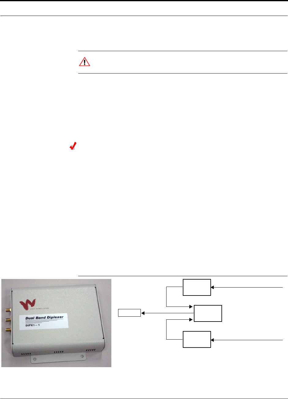
• 1 Dual-Band Diplexer (PN #DIPX1-1)
• 2 coaxial cables, 3 ft. long (PN #4005-3)
Installing RAUs in a Dual Band System
A Dual-Band Diplexer is used to combine the output of a low-band RAU and a
high-band RAU to a single dual band antenna.
Considerations:
• The Diplexer will have a high loss if it is connected incorrectly. When using it with
the Unison system, incorrect connections may trigger the Antenna Disconnect
alarm.
• When using the Dual-Band Diplexer, the Unison system Antenna Disconnect
alarm can detect if the cable is disconnected or cut between the RAU and the
Diplexer. This alarm, however, cannot detect if the cable is disconnected or cut
between the Diplexer and the antenna.
Figure 6-1 shows the RAU configuration in a dual band system. It consists of two
RAUs, one for upper band and one for lower band, a diplexer and two 3 ft. coaxial
cables.
Figure 6-1 Dual Band RAU Configuration
Unison
RAU
Unison
RAU
Dual Band
Diplexer
Cat-5/6 from Accel Hub
Cat-5/6 from Accel Hub
Antenna
3 ft. coaxial cable
3 ft. coaxial cable
6-18 InterReach Unison Accel Installation, Operation, and Reference Manual PN 9000-10
620021-0 Rev. A
To connect the RAUs and Dual Band Diplexer for a dual band system:
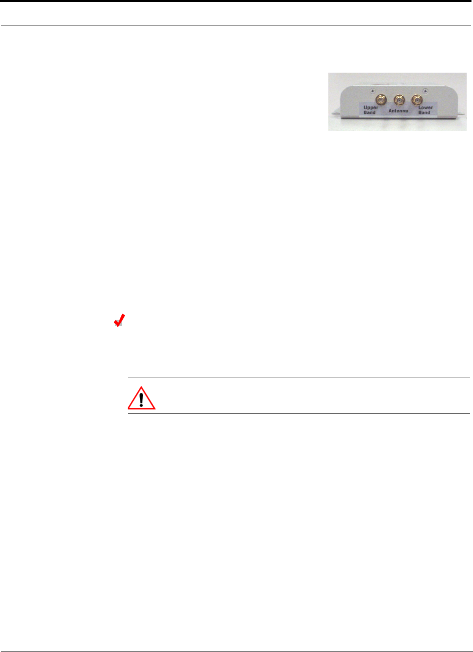
Connecting the Antenna to the Dual Band Diplexer
Connect a single passive antenna to the Dual Band Diplexer’s “Antenna” SMA con-
nector using coaxial cable with the least amount of loss possible.
CAUTION:Firmly hand-tighten the SMA female connector – DO NOT
over-tighten the connector.
1. Attach the Diplexer to a stable surface (i.e.,
wall, ceiling tile, pole).
Do not mount the Diplexer on top of an RAU.
2. Attach the two Unison RAUs to a stable sur-
face within 2.5 ft.
of the Diplexer (do not stack the RAUs on top of each other).
3. Verify that the Unison system is powered on.
4. The green LED on both of the RAUs should be lit.
5. Connect a coaxial cable to the antenna ports on each of the Unison RAUs.
6. The recommended coaxial cable (PN 4005-3) is 3 ft. long.
7. Connect the coaxial cable coming from the Unison lower band system (i.e., sys-
tem band below 1 GHZ) into the Diplexer port labeled “LOWER BAND.”
8. Connect the coaxial cable coming from the Unison upper band system (i.e., sys-
tem band above 1 GHZ) into the Diplexer port labeled “UPPER BAND.”
9. Connect a coaxial cable from the dual band antenna into the Diplexer port
labeled “ANTENNA.”
PN 9000-10 Help Hot Line (U.S. only): 1-800-530-9960 6-19
620021-0 Rev. A
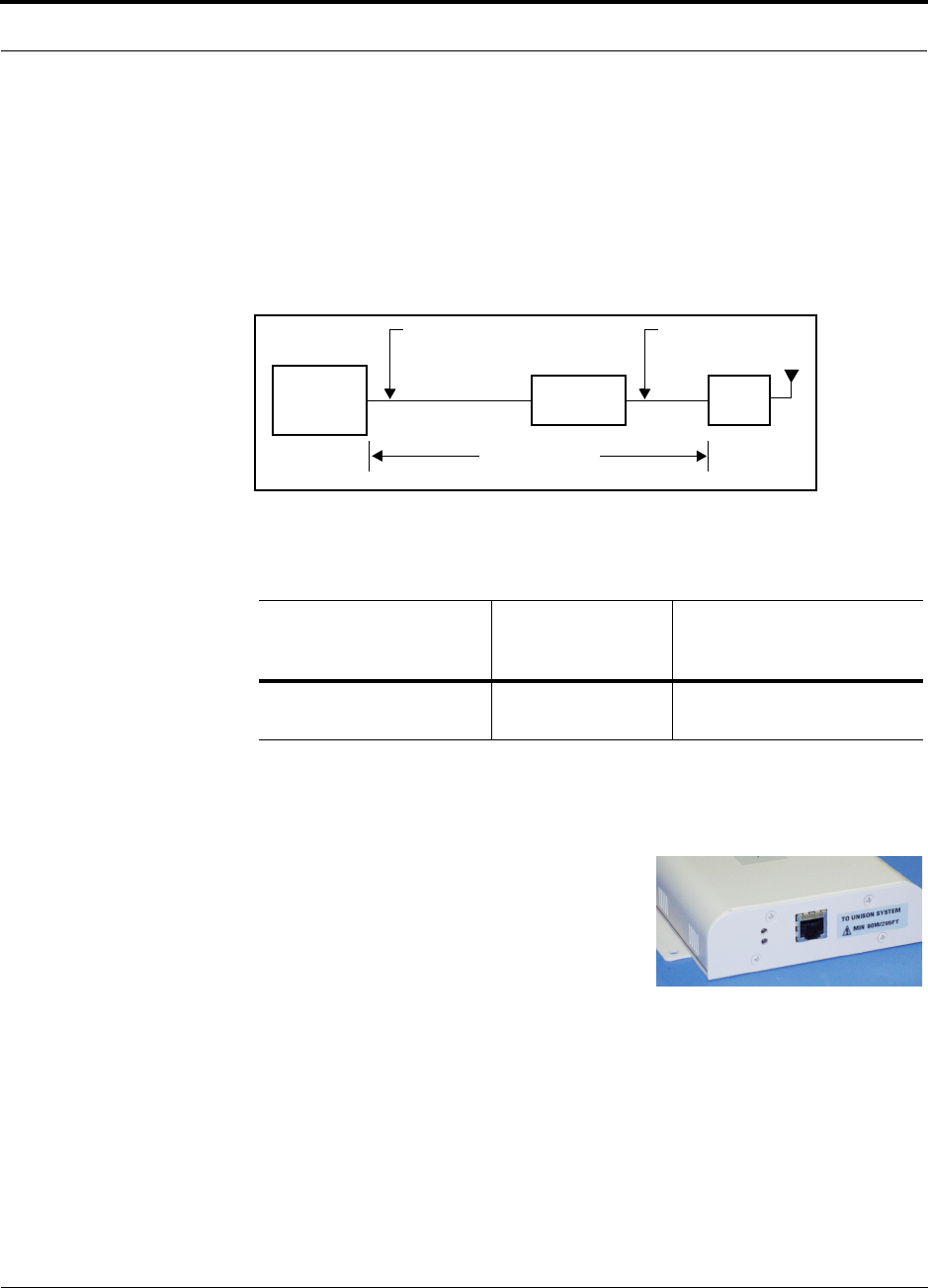
6.4.4 Installing Cat-5 Extender
The Cat-5 Extender (PN #UNS-EX170-1) increases the maximum length of the
Cat-5/6 ScTP cable run that connects the Accel Hub to the RAU from 100 meters to
170 meters. The minimum cable length between the Hub and Extender is 90 meters
and the minimum length between the Extender and RAU is 20 meters. Beyond the
minimum lengths, an additional 60 meters of cable, maximum of 170 meters total,
can be inserted before or after the Extender.
Considerations:
• Ensure that the following minimum and maximum cable lenghs are met:
To install a Cat-5 Extender:
Min. Cat-5/6 Cable
Length from Accel Hub
to Extender
Min. Cat-5/6 Cable
Length from
Extender to RAU
Max. Cat-5/6 Cable
Length from
Accel Hub to RAU
90 meters
295 feet
20 meters
65 feet
110 to 170 meters
360 to 557 feet
Accel
Hub
Unison
Cat-5/6 ScTP Cable
90 meters minimum
Unison Cat-5
Extender
Cat-5/6 ScTP Cable
20 meters minimum
170 meters maximum
RAU
295 feet minimum 65 feet minimum
557 feet maximum
1. Attach the Cat-5 Extender securely to a stationary object (i.e., wall, pole, ceiling
tile).
2. Attach the Cat-5/6 cable that is coming from
the Accel Hub to the TO UNISON SYSTEM con-
nector on the Extender.
If the green LED lights on the Extender, then you
have correctly connected the Cat 5/6 cable that is
connected to the Accel Hub.
If the LED does not light, then you may not have connected the cable at the Accel Hub. If
the cable is connected and the LED still does not light, then the Unison system may not be
powered on, the Cat-5 cable may be cut/broken, or there is a problem with the Extender.
Verify that the Accel Hub is connected to AC power and the power switch is in the ON
position.
3. Attach the Cat-5/6 cable that is coming from the RAU to the TO UNISON RAU
connector on the Extender.
CAUTION: Do not insert the RAU cable into the Extender until the green LED
on the Extender lights. Otherwise, you may damage the RAU.

6-20 InterReach Unison Accel Installation, Operation, and Reference Manual PN 9000-10
620021-0 Rev. A
6.4.5 Configuring the System
Configuring the Installed System
Considerations:
• The AdminManager PC/laptop is connected to the Main Hub.
• The AdminManager software is started.
• All system components are installed and powered on.
To configure an installed system:
1. Select the Installation Wizard (Local) radio button from the AdminManager main
window and click RUN.
The Step 1, Verify Hardware window is displayed.
2. Verify that all system devices are displayed in the System Status box and click
NEXT.
The Step 2, Set Operation Band window is displayed.
3. Click NEXT.
The Step 3, Configure System Parameters window is displayed.
4. Enter the desired parameters and click APPLY.
5. Click NEXT if the message that is displayed indicates that the parameter setting is
successful.
The Step 4, Final System Test window is displayed.
6. Click APPLY to initiate the final system test.
During testing the system is off-line and a center band tone is being transmitted.
7. Click NEXT if the message that is displayed indicates that the testing is successful.
The Finish window is displayed.
8. Click FINISH.
The AdminManager session is ended and the window closes.
All of the Main Hub’s LEDs should be green.
PN 9000-10 Help Hot Line (U.S. only): 1-800-530-9960 6-21
620021-0 Rev. A
6.5 Interfacing an Accel Hub to a Base Station or a
Roof-top Antenna
WARNING: Exceeding the maximum input power could cause failure
of the Accel Hub (refer to Section 5.1 on page 5-3 for maximum power
specifications). If the maximum composite power is too high, attenua-
tion is required.
Connecting an Accel Hub to an In-Building Base Station
Connecting a Simplex Base Station to an Accel Hub:
1. Connect an N-male to N-male coaxial cable to the transmit simplex connector on
the base station.
2. Connect the other end of the N-male to N-male coaxial cable to the DOWNLINK
connector on the Hub.
3. Connect an N-male to N-male coaxial cable to the receive simplex connector on
the base station.
4. Connect the other end of the N-male to N-male coaxial cable to the UPLINK con-
nector on the Hub.
Figure 6-2 Simplex Base Station to an Accel Hub
N-male to N-male
Coaxial Cable
Base Station
Simplex T1/E1 to
Mobile
Switching
Center
Insert attenuator, if needed
6-22 InterReach Unison Accel Installation, Operation, and Reference Manual PN 9000-10
620021-0 Rev. A
Connecting a Duplex Base Station to an Accel Hub:
When connecting to a duplex base station, use a circulator between it and the Accel
Hub.
You can insert attenuators between the circulator and Hub as needed; refer to
Section 5.5.1 on page 5-43 for more information.
1. Connect an N-male to N-male coaxial cable to the duplex connector on the base
station.
2. Connect the other N-male connector to a circulator.
3. Connect an N-male to N-male coaxial cable to the DOWNLINK connector on the
Hub.
4. Connect the other end of the N-male coaxial cable to the transmit connector on the
circulator.
5. Connect an N-male to N-male coaxial cable to the UPLINK connector on the Hub.
6. Connect the other end of the N-male coaxial cable to the receive connector on the
circulator.
Figure 6-3 Duplex Base Station to an Accel Hub
N-male to N-male
Coaxial Cable
Base Station
Duplex T1/E1 to
Mobile
Switching
Center
Insert attenuator, if needed N-male to N-male
Coaxial Cable
Circulator
PN 9000-10 Help Hot Line (U.S. only): 1-800-530-9960 6-23
620021-0 Rev. A
Connecting an Accel Hub to Multiple Base Stations
You can use power combiner/splitters to connect an Accel Hub to multiple base sta-
tions, as shown in the following figure.
Figure 6-4 Connecting an Accel Hub to Multiple Base Stations
N-male to N-male
Coaxial Jumper Cables
N-male to N-male
Coaxial Jumper Cable
to Repeater or
Base Station
between Combiner/Splitter and
N-male to N-male
Coaxial Jumper Cables
between Combiner/Splitter and
Accel Hub’s Uplink Port Accel Hub’s Downlink Port
2 x 1 Power
Combiner/Splitter 2 x 1 Power
Combiner/Splitter
BTS 1
UL DL
BTS 2
UL DL
Insert attenuators, if needed
6-24 InterReach Unison Accel Installation, Operation, and Reference Manual PN 9000-10
620021-0 Rev. A
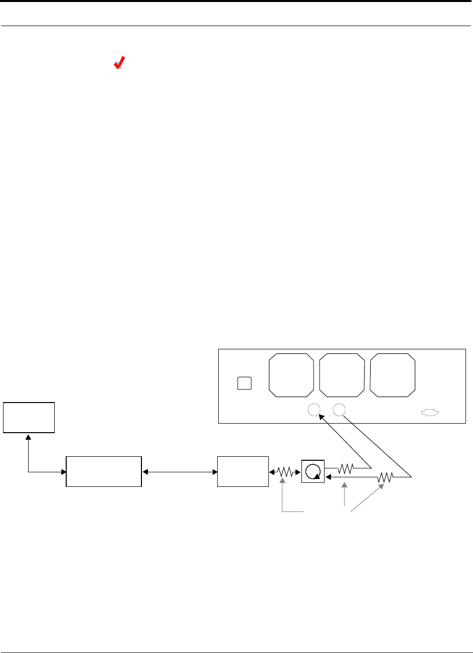
Connecting an Accel Hub to a Roof-top Antenna
It is recommended that you use a lightning arrestor or surge protector in a roof-top
antenna configuration. Insert the lightning arrestor or surge protector between the
roof-top antenna and the repeater that is connected to the Accel Hub.
1. Connect an N-male to N-male coaxial cable to the roof-top antenna.
2. Connect the other end of the N-male to N-male coaxial cable to the grounded
surge suppressor.
3. Connect an N-male to N-male coaxial cable to the grounded surge suppressor.
4. Connect the other end of the N-male to N-male coaxial cable to the repeater.
5. Connect an N-male to N-male coaxial cable to the repeater.
6. Connect the other end of the N-male to N-male coaxial cable to the circulator
1connector.
7. Connect an N-male to N-male coaxial cable to the circulator 2connector.
8. Connect the other end of the N-male to N-male coaxial cable to the DOWNLINK
connector on the Hub.
Attenuation may be required to achieve the desired RF output at the RAU.
9. Connect an N-male to N-male coaxial cable to the circulator 3connector.
10. Connect the other end of the N-male to N-male coaxial cable to the UPLINK con-
nector on the Hub.
Roof-top
Antenna
Grounded
Surge Suppressor Repeater
N-male to N-male
Coaxial Cables
N-male to N-male
Coaxial Cable
N-male to N-male
Coaxial Cable Circulator
Attenuator
(optional)

PN 9000-10 Help Hot Line (U.S. only): 1-800-530-9960 6-25
620021-0 Rev. A
6.5.1 Connecting Multiple Accel Hubs
You can use power combiner/splitters as splitters to connect multiple Accel Hubs in
order to increase the total number of RAUs in a system. You can also use power com-
biner/splitters to combine base station channels in order to increase the number of RF
carriers the system transports.
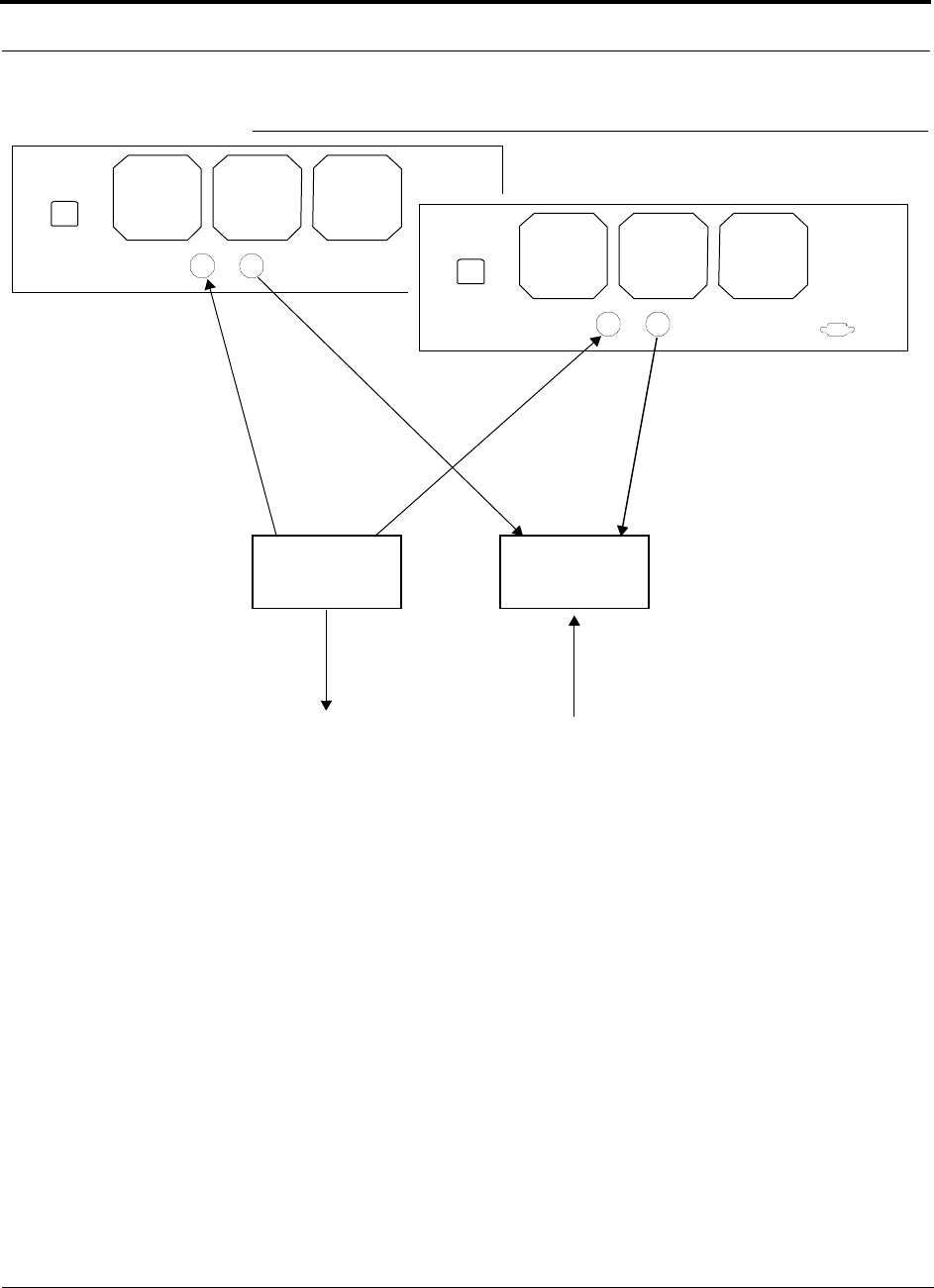
Connecting Multiple Accel Hubs to a Simplex Repeater
or Base Station
Considerations:
• 2 hybrid power combiner/splitters; one for uplink and one for downlink (2x1 for
two Accel Hubs, 3x1 for three, 4x1 for four, etc.)
• 1 N-male to N-male coaxial jumper cable between each power combiner/splitter
and the base station
• 2 N-male to N-male coaxial jumper cables between each power combiner/splitter
and each Accel Hub
Procedure:
1. Connect the power combiner/splitters to the repeater or base station using N-male
to N-male coaxial jumper cables:
b. From the first power combiner/splitter to the repeater or base station
c. From the second power combiner/splitter to the repeater or base station
2. Connect the power combiner/splitters to the Hubs:
a. From the first Hub’s UPLINK port to the first power combiner/splitter
b. From the first Hub’s DOWNLINK port to the second power combiner/splitter
c. From the second Hub’s UPLINK port to the first power combiner/splitter
d. From the second Hub’s DOWNLINK port to the second power combiner/splitter
3. Check Hub LEDs.
After connecting and powering on the Hub, check all LEDs to ensure that the sys-
tem is operating properly.
NOTE: Use a 50 ohm terminator on any unused power combiner/splitter ports.
The following figure shows connecting two Hubs to a simplex repeater or base sta-
tion. Connecting two Hubs increases the total number of supportable RAUs from 8 to
16.
6-26 InterReach Unison Accel Installation, Operation, and Reference Manual PN 9000-10
620021-0 Rev. A
Figure 6-5 Connecting Two Accel Hubs to a Simplex Repeater or Base Station
N-male to N-male
Coaxial Jumper Cables
N-male to N-male
Coaxial Jumper Cable
to Repeater or
Base Station
2 x 1 Power
Combiner/Splitter
N-male to N-male
Coaxial Jumper Cable
to Repeater or
Base Station
between Combiner/Splitter and
N-male to N-male
Coaxial Jumper Cables
between Combiner/Splitter and
Accel Hub’s Downlink Port Accel Hub’s Uplink Port
2 x 1 Power
Combiner/Splitter

PN 9000-10 Help Hot Line (U.S. only): 1-800-530-9960 6-27
620021-0 Rev. A
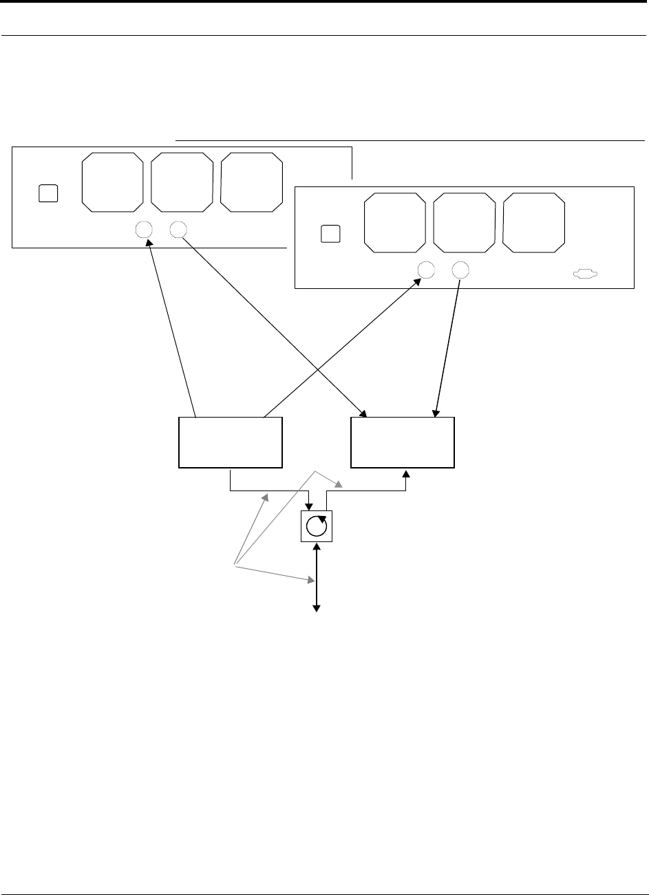
Connecting Multiple Accel Hubs to a Duplex Repeater
or Base Station
Considerations:
• 2 hybrid power combiner/splitters; one for uplink and one for downlink (2x1 for
two Accel Hubs, 3x1 for three, 4x1 for four, etc.)
• 2 N-male to N-male coaxial jumper cables to connect each Accel Hub to the power
combiner/splitters
• 1 circulator
• 1 N-male to N-male coaxial jumper cable between each circulator and the repeater
or base station
• 1 N-male to N-male coaxial jumper cable1 between each circulator and power
combiner/splitter
Procedure:
1. Connect the Circulator to the power combiner/splitters and to the repeater or base
station using one N-male to N-male coaxial jumper cable.
2. Connect each power combiner/splitter to the circulator using one N-male to
N-male coaxial jumper cable.
3. Connect the power combiner/splitter to the Hubs:
a. From the first Hub’s UPLINK port to the first power combiner/splitter
b. From the first Hub’s DOWNLINK port to the second power combiner/splitter
c. From the second Hub’s UPLINK port to the first power combiner/splitter
d. From the second Hub’s DOWNLINK port to the second power combiner/splitter
4. Check Hub LEDs.
After connecting and powering on the Hub, check all LEDs to ensure that the sys-
tem is operating properly.
NOTE: Use a 50 ohm terminator on any unused power combiner/splitter ports.
6-28 InterReach Unison Accel Installation, Operation, and Reference Manual PN 9000-10
620021-0 Rev. A
To connect two Hubs to a duplex repeater or base station, you need to use one circu-
lator and one more coaxial jumper cable, as shown in the following figure.
Figure 6-6 Connecting Two Accel Hubs to a Duplex Repeater or Base Station
N-male to N-male
Coaxial Jumper Cables
2 x 1 Power
Combiner/Splitter
between Combiner/Splitter and
N-male to N-male
Coaxial Jumper Cables
between Combiner/Splitter and
Accel Hub’s Downlink Port Accel Hub’s Uplink Port
2 x 1 Power
Combiner/Splitter
N-male to N-male
Coaxial Jumper Cable
N-male to N-male
Coaxial Jumper Cable
Circulator
N-male to N-male
Coaxial Jumper Cable
to Repeater or
Base Station
Insert attenuator, if needed

PN 9000-10 Help Hot Line (U.S. only): 1-800-530-9960 6-29
620021-0 Rev. A
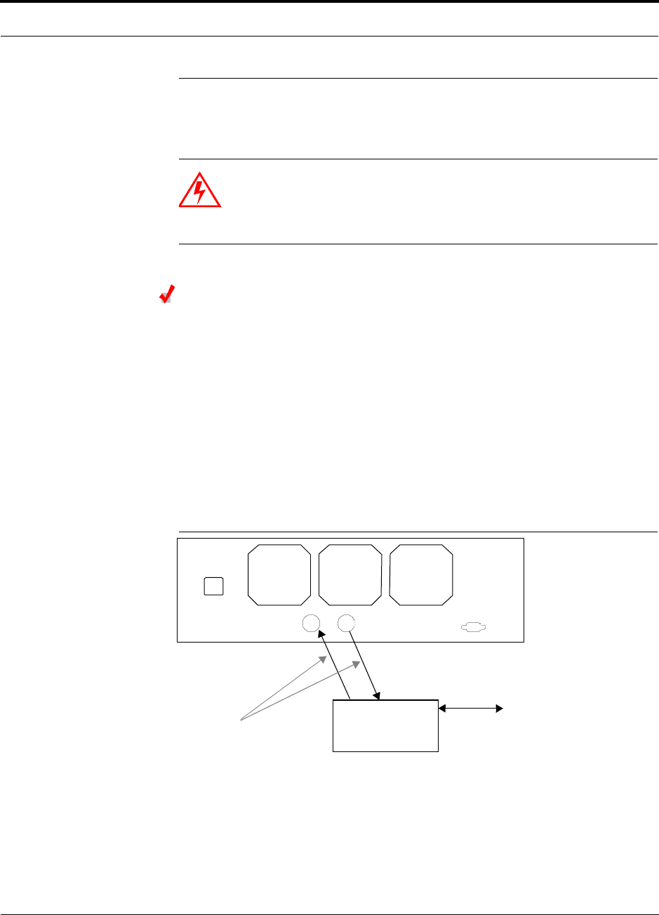
6.6 Connecting Contact Alarms to an Accel System
The Accel Hub can generate (source) two contact alarms as well as sense an external
contact alarm.
• Alarm Source (see Section 6.6.1 on page 6-30)
The Accel Hub has two alarm contacts, fault (major) and warning (minor). These
contact are normally-closed (NC) and will open when an internal alarm is detected.
• Fault is activated when any faults or disconnects are detected.
• Warning is activated when any warning conditions are detected except lockout
or when the end-to-end system test is not valid.
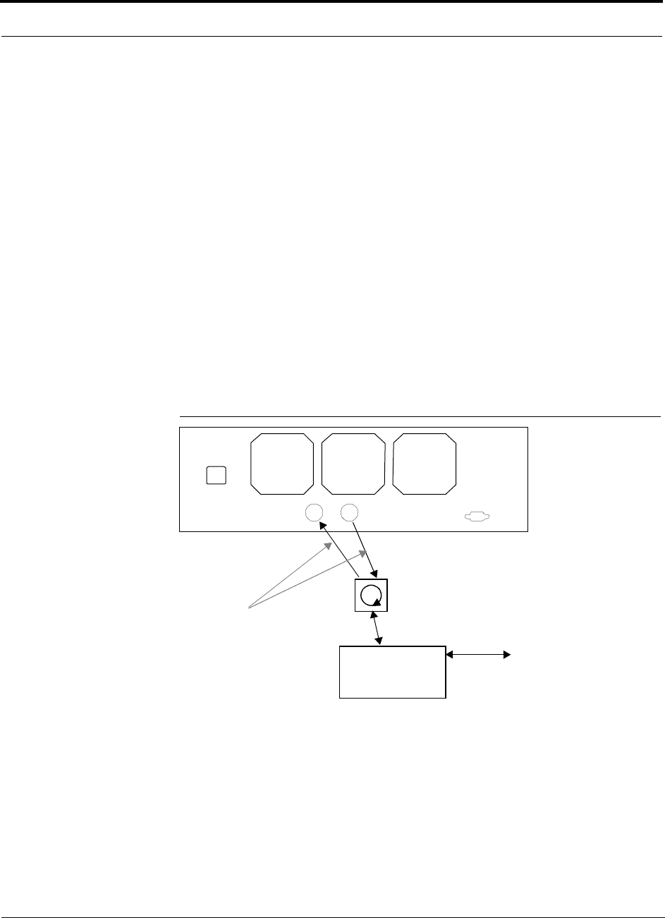
• Alarm Sense (see Section 6.6.2 on page 6-33)
The Accel Hub can monitor an external alarm contact. The port can be configured
for normally-open (NO) or normally-closed (NC) contacts. The interface expects a
set of floating contacts, and an external voltage source is not required for this inter-
face. AdminManager is used to monitor the port status.
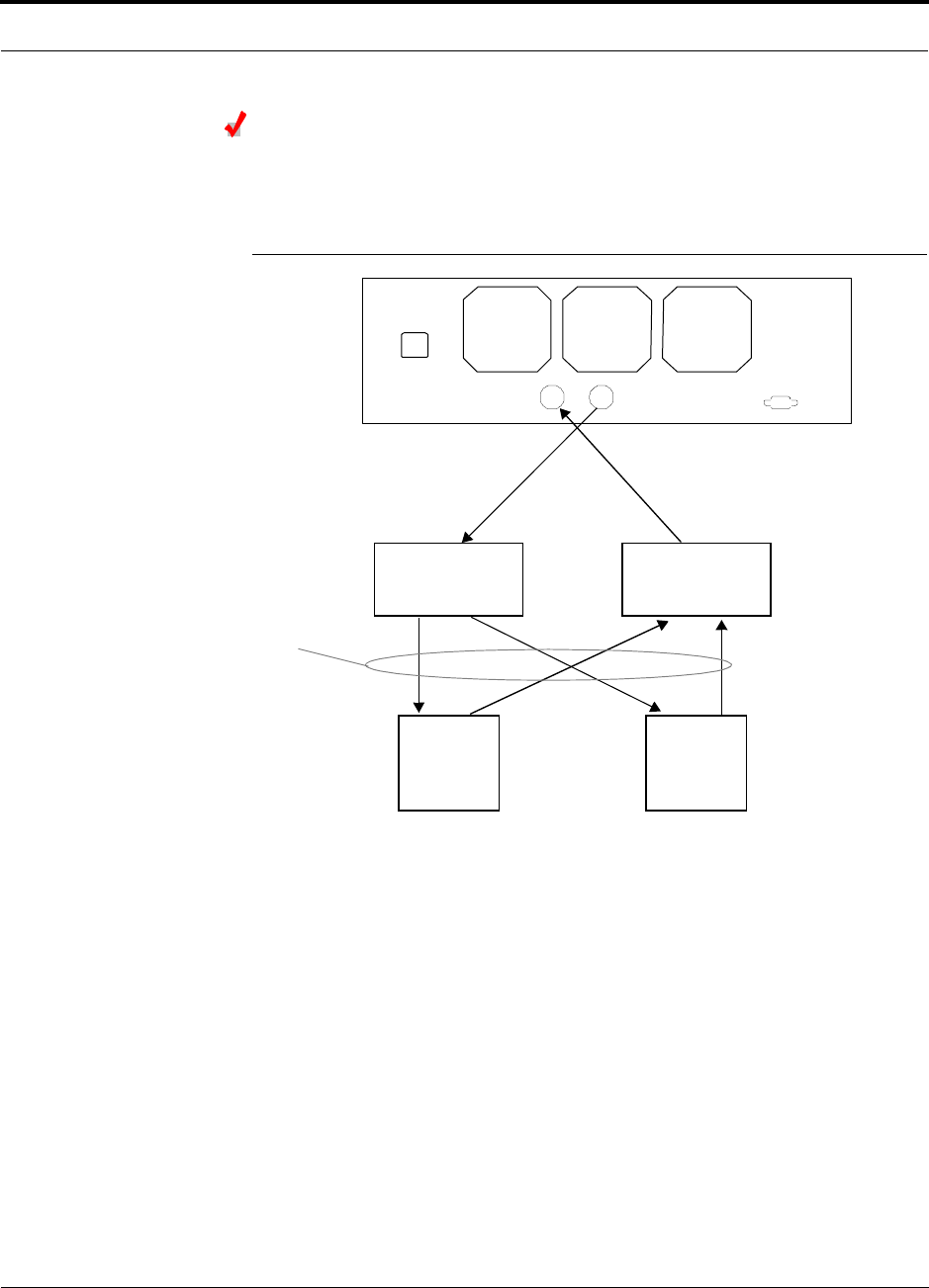
The following table lists the alarm types, equipment that Accel is connected to,
cable(s) used, and the errors (major and/or minor) that are detected.
Note that LGCell and MetroReach Focus support only faults (major errors).
Do not mix LGCell and Unison Accel Hubs in the same daisy-chain. You can
daisy-chain multiple LGCell Main Hubs together and use the Alarm Sense Adapter
Cable to connect the chain to a Unison Accel Hub, which will act as an alarm sensor.
Alarm
Type Unison
connected to Cable(s) Used Errors Detected
Source MetroReach 5-port Alarm Daisy-Chain Cable Faults
Source BTS 5-port Alarm Daisy-Chain Cable Faults and Warnings
In addition, a custom daisy-chain cable-to-BTS interface
cable is required. Make this interface cable to the desired
length and with the appropriate pin placement.
Sense LGCell 5-port Alarm Daisy-Chain Cable
and the Alarm Sense Adapter
Cable
Faults
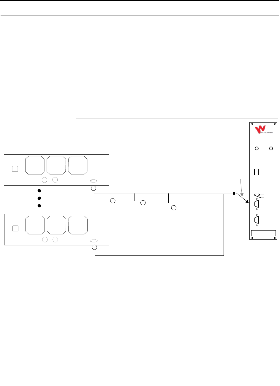
6-30 InterReach Unison Accel Installation, Operation, and Reference Manual PN 9000-10
620021-0 Rev. A
6.6.1 Alarm Source
Unison always acts an alarm source, no matter what type of equipment you are con-
necting to. Refer to Section 6.6.2 on page 6-33 if you want Unison Accel to sense
LGCell contact closures or other external alarms.
Using MetroReach Focus to Monitor Unison Accel
When you connect MetroReach Focus to Unison Accel, the Unison Accel Hub is the
output of the alarms (alarm source) and Focus is the input (alarm sense), as shown in
the following figure. Focus supports only faults (major errors).
Figure 6-7 Connecting MetroReach to Unison Accel
RF OUT
DOWNLINK RF IN
UPLINK
FIBER
UPLINK
DOWNLINK
ALARM
RS-232C
MetroReach
Focus
RFM
Alarm
Sense
Alarm
Source
Alarm
Source
5-port Alarm Daisy-Chain Cable
May need
9-pin Adapter,
which ships
with the cable
Unison Accel Hub
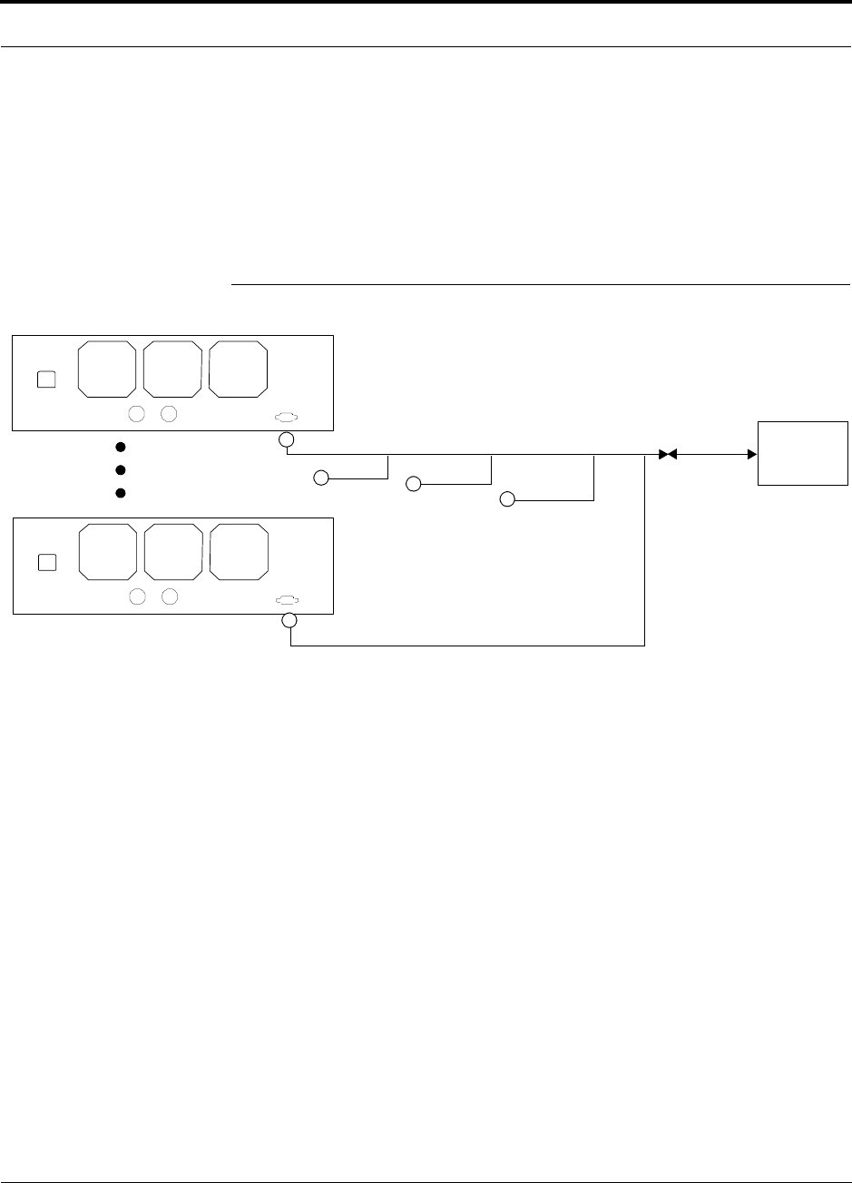
PN 9000-10 Help Hot Line (U.S. only): 1-800-530-9960 6-31
620021-0 Rev. A
Using a Base Station to Monitor Unison Accel
When you connect a BTS to Unison Accel, the Unison Accel Hub is the output of the
alarms (alarm source) and the BTS is the input (alarm sense), as shown in the follow-
ing figure. An interface cable is required between the daisy-chain cable and the BTS.
Because BTS alarm interface pinouts and Accel-to-BTS distances vary, this cable
often is custom and wired on-site.
Figure 6-8 Using a BTS to Monitor Unison Accel
BTS
Interface
Cable
Alarm
Sense
Alarm
Source
Alarm
Source
5-port Alarm Daisy-Chain Cable
Unison Accel Hub
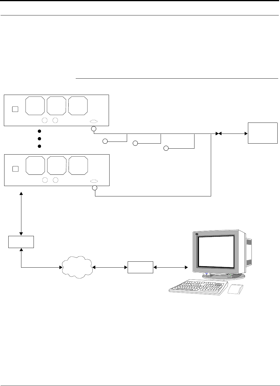
6-32 InterReach Unison Accel Installation, Operation, and Reference Manual PN 9000-10
620021-0 Rev. A
Using a Base Station and AdminManager to Monitor Unison Accel
In order to take full advantage of Unison Accel’s OA&M capabilities you can use
LGC Wireless’ AdminManager software in addition to a BTS to monitor the system,
as shown in Figure 6-9.
Figure 6-9 Using a BTS and AdminManager to Monitor Unison Accel
Modem
Straight-through modem cable connected
to Accel Hub’s front panel serial port
PSTN Modem
PC running
AdminManager
Software
BTS
Interface
Cable
Alarm
Sense
Alarm
Source
Alarm
Source
5-port Alarm Daisy-Chain Cable
Unison Accel Hub
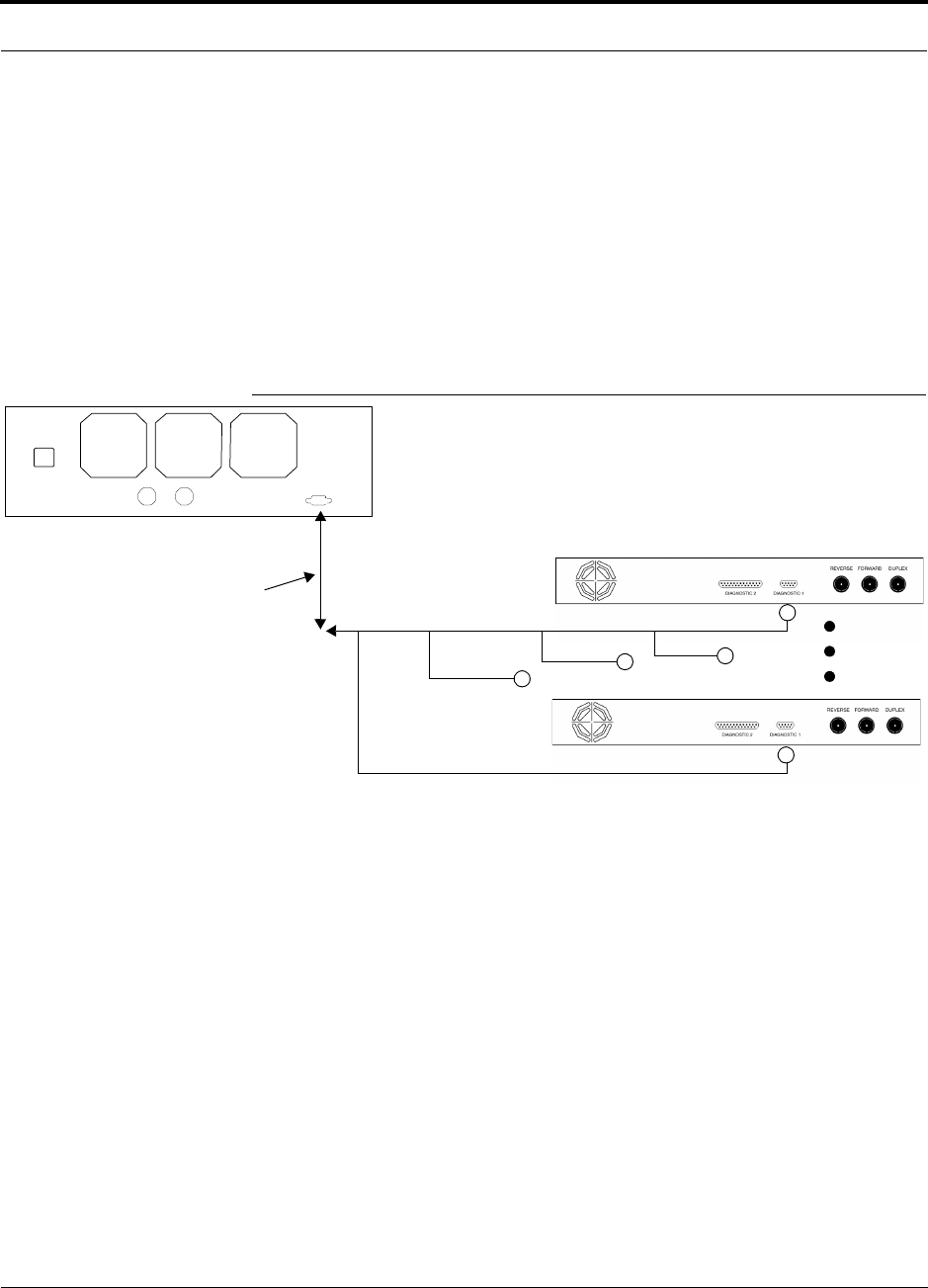
PN 9000-10 Help Hot Line (U.S. only): 1-800-530-9960 6-33
620021-0 Rev. A
6.6.2 Alarm Sense
Use AdminManager to enable the Unison Accel system for “alarm sense” when con-
necting to the contact closure of LGCell Main Hubs or other external alarms (see Set
Contact Sense Properties in the AdminManager User Manual).
Using Unison Accel to Monitor LGCells
When you connect LGCell to Unison Accel, the Unison Accel Hub is the input of the
alarms (alarm sense) and the LGCell is the output (alarm source), as shown in the fol-
lowing figure.
Figure 6-10 Connecting LGCell to Unison Accel
LGCell supports only faults (major errors). You must use the Alarm Sense Adapter
Cable (see page 6-35) to interface the daisy-chain cable to Unison Accel. The adapter
cable is required because it translates the LGCell fault pinout to the sense input pins
on the Unison Accel Hub.
Up to 5 LGCell Main Hubs
Unison Accel Hub
Alarm
Sense Alarm
Source
Alarm
Source
Alarm Sense
Adapter Cable
5-port Alarm Daisy-Chain Cable
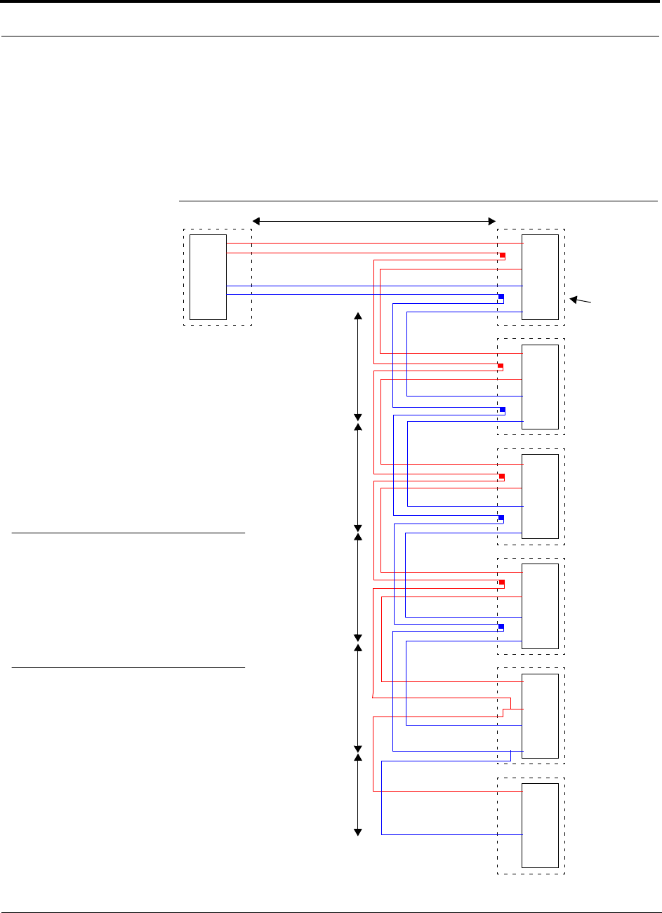
6-34 InterReach Unison Accel Installation, Operation, and Reference Manual PN 9000-10
620021-0 Rev. A
6.6.3 Alarm Cables
5-port Alarm Daisy-Chain Cable
Figure 6-11 shows the 5-port Alarm Daisy-Chain Cable (PN 4024-3), which supports
fault and warning conditions (i.e., major and minor errors).
Figure 6-11 5-port Alarm Daisy-Chain Cable
DB-9 female to
Base Station,
MetroReach Focus,
ARM2000-RU, or
J1
Female J2
Male
J3
Male
J4
Male
J5
Male
J6
Male
J7
Female
Terminator
Splice
Splice
Splice
Splice
Splice
Splice
Splice
Splice
7
9
4
5
7
9
4
5
7
9
4
5
7
9
4
5
7
9
4
5
7
4
1.2 meters (4 feet)
.5 meter
(1.5 feet)
DB-9 male to
Unison, MetroReach
Focus, or LGCell
Alarm Port
DB-9 male to
Unison, MetroReach
Focus, or LGCell
Alarm Port
DB-9 male to
Unison, MetroReach
Focus, or LGCell
Alarm Port
DB-9 male to
Unison, MetroReach
Focus, or LGCell
Alarm Port
Option 1: DB-9 to
Unison, MetroReach
Focus, or LGCell
Alarm Port.
J7 not used
Option 2: Use J2-J5
for alarm ports. J6 is used
to connect to an additional
Alarm Daisy-Chain Cable.
J7 is not used.
Option 3: Connect
fewer than 5 ports and
terminate the daisy chain
by connecting J7 to the
lowest unused port.
Connector
Hood
.5 meter
(1.5 feet)
.5 meter
(1.5 feet)
.5 meter
(1.5 feet)
.25 meter
(.75 feet)
the Alarm Sense
Adapter Cable when
connecting LGCell
NOTE: Do not daisy-chain Unison
Accel Hubs with LGCell or
MetroReach if you want both faults
and warnings from Unison. Only faults
are reported if you combine Unison
Accel with LGCell or MetroReach in
the same daisy chain.
to Unison
7
9
4
5
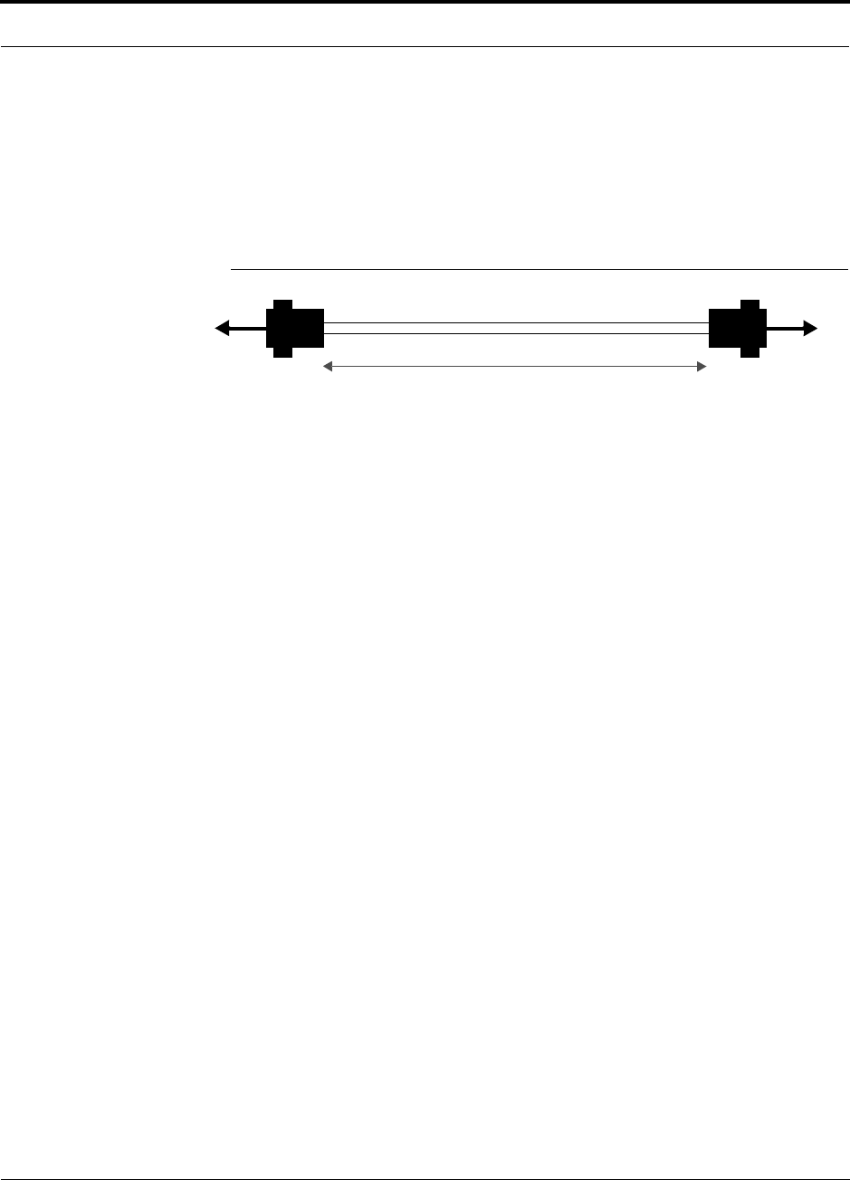
PN 9000-10 Help Hot Line (U.S. only): 1-800-530-9960 6-35
620021-0 Rev. A
Alarm Sense Adapter Cable
The alarm sense adapter cable (PN 4025-1) translates the LGCell fault pinout to the
sense input pins on the Unison Accel Hub. You must use this adapter cable, as illus-
trated in Figure 6-12, with the 5-port Alarm Daisy-Chain Cable when connecting
LGCell to Unison.
Figure 6-12 Alarm Sense Adapter Cable
J8
1
8
J9
7
9
To Unison Accel To Daisy-Chain Cable
3 feet
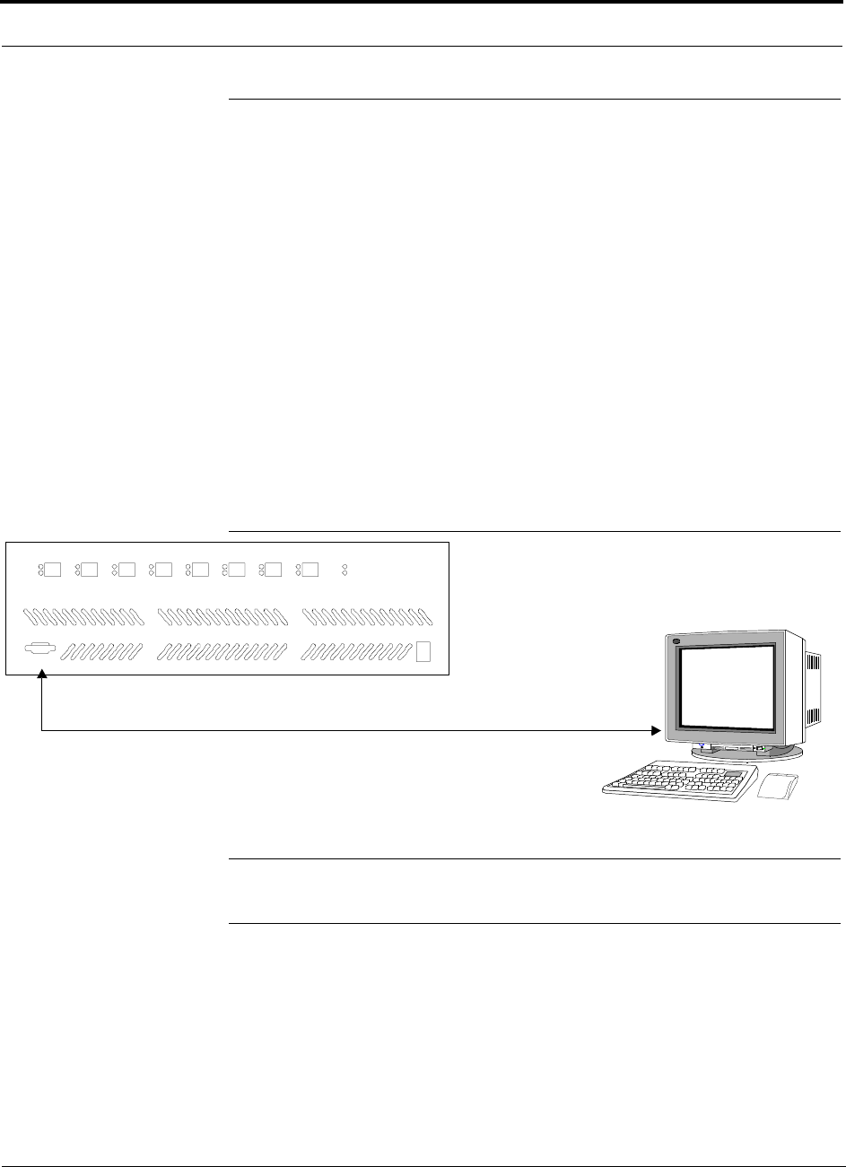
6-36 InterReach Unison Accel Installation, Operation, and Reference Manual PN 9000-10
620021-0 Rev. A
6.7 Alarm Monitoring Connectivity Options
The following connectivity options are described here:
• Section 6.7.1 Direct Connection . . . . . . . . . . . . . . . . . . . . . . . . . . . . . . . . . . . 6-36
• Section 6.7.2 Modem Connection . . . . . . . . . . . . . . . . . . . . . . . . . . . . . . . . . . 6-37
• Section 6.7.3 232 Port Expander Connection . . . . . . . . . . . . . . . . . . . . . . . . . 6-38
• Section 6.7.4 POTS Line Sharing Switch Connection . . . . . . . . . . . . . . . . . . 6-39
• Section 6.7.5 Ethernet and ENET/232 Serial Hub Connection . . . . . . . . . . . 6-40
Note that the only accessory that is available through LGC Wireless is the DB-9 to
DB-9 null modem cable, which is provided with AdminManager.
6.7.1 Direct Connection
In this configuration, the AdminManager PC connects directly to the RS-232 serial
port on the Accel Hub’s front panel using a null modem cable.
Figure 6-13 OA&M Direct Connection
NOTE: The null modem cable must support full hardware handshaking.
See Appendix A.4 on page A-4 for cable wiring information.
PC running
Software
Null Modem Cable
AdminManager
LINK
RAU
PORT 1
LINK
RAU
PORT 2
LINK
RAU
PORT 3
LINK
RAU
PORT 4
LINK
RAU
PORT 5
LINK
RAU
PORT 6
LINK
RAU
PORT 7
LINK
RAU
PORT 8
POWER
STATUS
POWER
InterReach
Unison Accel
RS-232
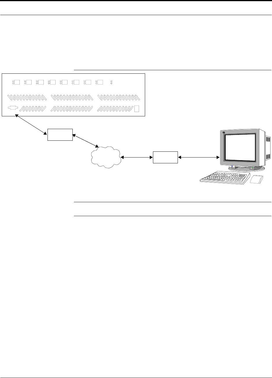
PN 9000-10 Help Hot Line (U.S. only): 1-800-530-9960 6-37
620021-0 Rev. A
6.7.2 Modem Connection
In this configuration, the PC and the Accel Hub connect to modems and communicate
via a standard dial-up telephone connection.
Figure 6-14 OA&M Modem Connection
NOTE: See Appendix A.3 on page A-3 for the modem cable wiring information.
Straight-through
modem cable
PC running
Software
AdminManager
LINK
RAU
PORT 1
LINK
RAU
PORT 2
LINK
RAU
PORT 3
LINK
RAU
PORT 4
LINK
RAU
PORT 5
LINK
RAU
PORT 6
LINK
RAU
PORT 7
LINK
RAU
PORT 8
POWER
STATUS
POWER
InterReach
Unison Accel
RS-232
Modem
Straight-through modem cable
PSTN Modem
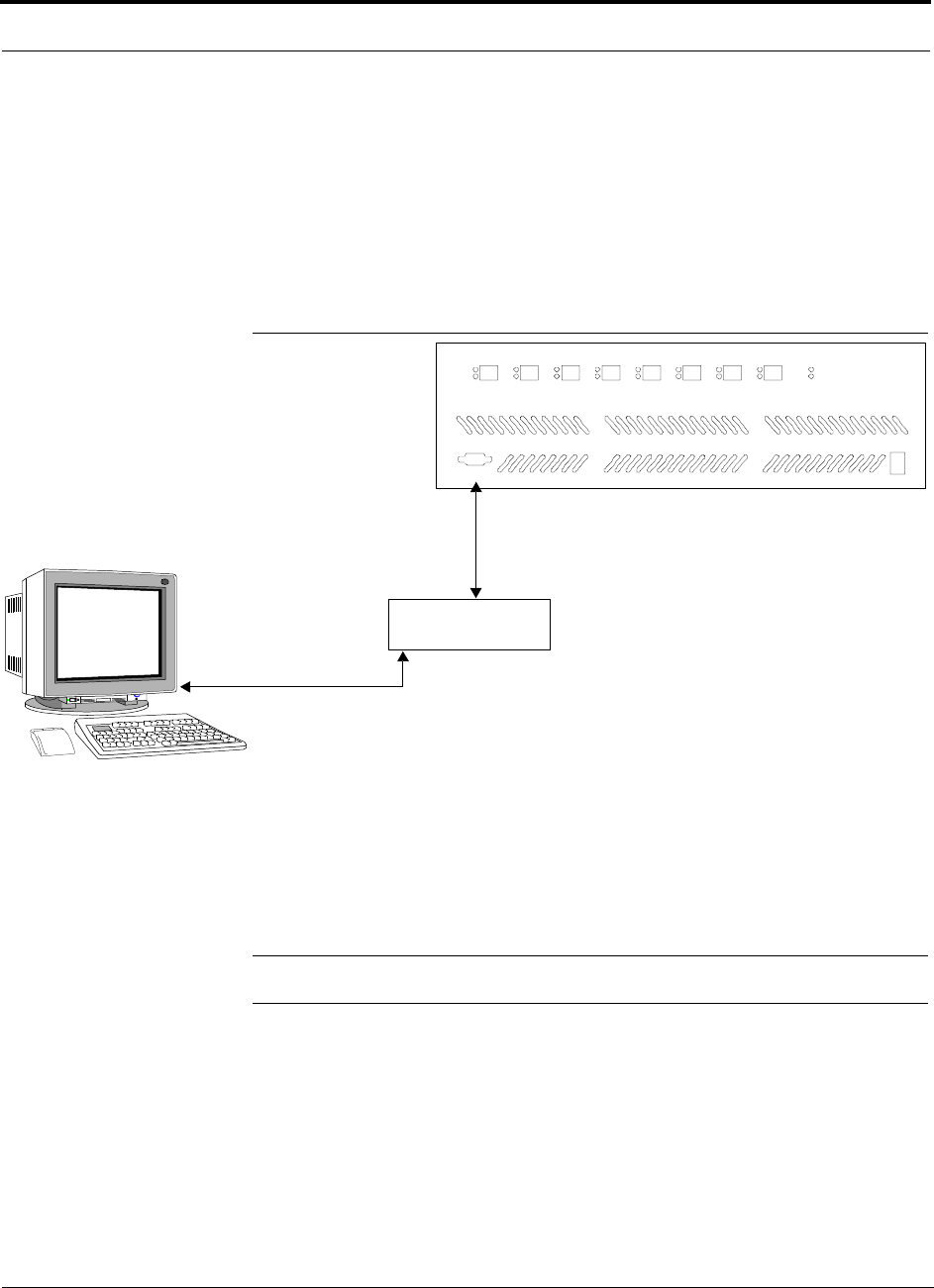
6-38 InterReach Unison Accel Installation, Operation, and Reference Manual PN 9000-10
620021-0 Rev. A
6.7.3 232 Port Expander Connection
In this configuration a port expander is used to allow the connection of multiple
devices to a single PC serial port. Testing was performed with an Equinox SST-16P
Multiport Board. A DB-25 male to DB-9 female modem cable must be made to con-
nect the connector panel to the Accel Hub (refer to Appendix A.5 on page A-5). Or,
you can use a DB-25 male/DB-9 male adapter with a DB-9 female to DB-9 female
null modem cable.
Figure 6-15 OA&M Connection using a 232 Port Expander
NOTE: See Appendix A.5 on page A-5 for the modem cable wiring information.
232 Port Expander
Host Cable
Serial Expansion Card to Connector Panel
Connector Panel
DB-25 male to DB-9 female
Modem Cable
PC running
Software
AdminManager
LINK
RAU
PORT 1
LINK
RAU
PORT 2
LINK
RAU
PORT 3
LINK
RAU
PORT 4
LINK
RAU
PORT 5
LINK
RAU
PORT 6
LINK
RAU
PORT 7
LINK
RAU
PORT 8
POWER
STATUS
POWER
InterReach
Unison Accel
RS-232
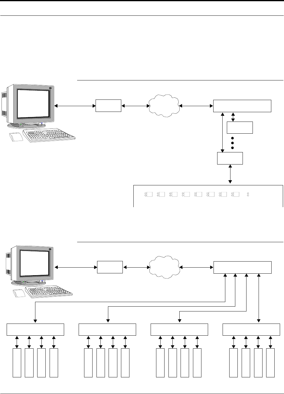
PN 9000-10 Help Hot Line (U.S. only): 1-800-530-9960 6-39
620021-0 Rev. A
6.7.4 POTS Line Sharing Switch Connection
Using a line sharing switch you can connect up to four modems to a single telephone
line. Testing was performed with a Teltone Line Sharing Switch, model number
M-394-B-01.
Figure 6-16 OA&M Connection using a POTS Line Sharing Switch
Up to 16 modems can be monitored using a single telephone line by cascading line
sharing switches, as shown in Figure 6-17.
Figure 6-17 Cascading Line Sharing Switches
LINK
RAU
PORT 1
LINK
RAU
PORT 2
LINK
RAU
PORT 3
LINK
RAU
PORT 4
LINK
RAU
PORT 5
LINK
RAU
PORT 6
LINK
RAU
PORT 7
LINK
RAU
PORT 8
POWER
STATUS InterReach
Unison Accel
Modem
PSTN
Line Sharing Switch
Up to 4 modems
per Switch
Modem
Modem
Straight-through
modem cable
Straight-through
modem cable
PC running
Software
AdminManager
Modem
PSTN
Line Sharing Switch
Line Sharing Switch Line Sharing Switch Line Sharing Switch Line Sharing Switch
M
o
d
e
m
M
o
d
e
m
M
o
d
e
m
M
o
d
e
m
M
o
d
e
m
M
o
d
e
m
M
o
d
e
m
M
o
d
e
m
M
o
d
e
m
M
o
d
e
m
M
o
d
e
m
M
o
d
e
m
M
o
d
e
m
M
o
d
e
m
M
o
d
e
m
M
o
d
e
m
Straight-through
modem cable
Straight-
through
modem
cables
PC running
Software
AdminManager
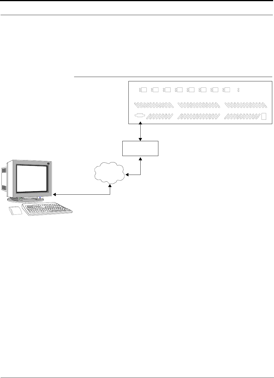
6-40 InterReach Unison Accel Installation, Operation, and Reference Manual PN 9000-10
620021-0 Rev. A
6.7.5 Ethernet and ENET/232 Serial Hub Connection
An Ethernet-to-RS-232 serial hub or converter box can be used to communicate
between the PC and Unison Accel. Testing was performed with an Equinox SST
Ethernet Serial Provider.
Figure 6-18 OA&M Connection using Ethernet and ENET/232 Serial Hub
ENET/232
Serial Hub
TCP/IP
Ethernet
Modem Cable
RJ-45 to DB-9 female
Cat-5
PC running
Software
AdminManager
LINK
RAU
PORT 1
LINK
RAU
PORT 2
LINK
RAU
PORT 3
LINK
RAU
PORT 4
LINK
RAU
PORT 5
LINK
RAU
PORT 6
LINK
RAU
PORT 7
LINK
RAU
PORT 8
POWER
STATUS
POWER
InterReach
Unison Accel
RS-232

PN 9000-10 InterReach Unison Accel Installation, Operation, and Reference Manual 7-1
620021-0 Rev. A
SECTION 7 Replacing Unison Accel
Components in an Operational
System
7.1 Replacing an RAU
Be aware that the new RAU must be the same band as the one you are replacing. If
you replace an RAU with one that is of the wrong band, it will not work.
The Accel Hub automatically checks the band of a replaced RAU. There is no need to
issue commands directly from the Hub. Therefore, as long as the RAU is of the cor-
rect band, the system will operate properly.
Replacing an RAU
1. Use AdminManager or refer to the As-Built Document to review the current
RAU’s configuration. To use AdminManager:
a. Select Get Unit Info command from the Configuration and Maintenance
Panel.
The Options dialog box is displayed (see Get Unit Info in the AdminManager
User Manual, PN 8810-10).
b. Select Remote Access Unit radio button.
c. Enter the hierarchy of the RAU in the text box.
For example, for RAU number 4 that is connected to Expan-
sion Hub number 1, enter 1-4.
d. Click OK.
Information for the RAU is displayed in the Configuration and Maintenance
Panel window.
5. Disconnect the Cat-5/6 cable and antenna from the unit to be replaced.
6. Install the new RAU.
7. Connect the antenna and then the Cat-5/6 cable to the new RAU.
8. Repeat Step 1 to verify that the new RAU is of the same frequency band as the
one replaced.

7-2 InterReach Unison Accel Installation, Operation, and Reference Manual PN 9000-10
620021-0 Rev. A
AdminManager Tasks
• Use the Advanced RAU Settings option on the Configuration & Maintenance
panel to set the RAU’s 10 dB attenuation and UL ALC settings.
• When convenient, perform System Test to optimize performance.
During System Test, the entire system is temporarily off-line and no RF is
being transmitted.
Checking the RAU’s LEDs
1. The RAU’s LINK and ALARM LEDs should blink (green/red) on power up.
• If the LEDs do not blink on power up, replace the RAU.
2. After several seconds both LEDs should change to green, which indicates that the
unit has been successfully replaced, there is communication with the Hub, and the
RAU band is correct.
a. If the LINK LED remains green and the ALARM LED remains red, verify that
the RAU model is correct for the intended frequency band.
– Disconnect the cable and then reconnect it once; doing this more than once
will not change the result.
b. If both LEDs still don’t change to green, use the AdminManager to determine
the exact nature of the fault and see a recommendation of how to correct it.
c. If both LEDs turn red (after 45 seconds), the Hub has terminated communica-
tions.

PN 9000-10 Help Hot Line (U.S. only): 1-800-530-9960 7-3
620021-0 Rev. A
7.2 Replacing an Accel Hub
You must record the system configuration settings from the old Accel Hub’s memory
before replacing the unit (see Get System Configuration Settings below). You will
program the new Hub with this information. If the Hub is programmed incorrectly,
the system will not work. If the Hub is not functioning, get the configuration settings
from the As-Built Document that was created as part of the original installation.
Get System Configuration Settings
1. Connect the null modem cable to the PC/laptop and the Accel Hub.
2. Start the AdminManager software.
3. Select the Configuration & Maintenance Panel option from the AdminManager
main window.
4. Click the SAVE CONFIG button.
The Save Configuration Notes dialog box is displayed.
5. Type any notes you want to save with the configuration settings into the dialog
box and click OK.
The configuration settings are saved in a text file, for example:
Begin Notes *******************************************
LGC HQ
05/23/01 MH configuration L010MH11
System configuration
End Notes *********************************************
Frequency Band is DCS Low.
SystemGain:UL=12dB,DL=4dB.
Callback Number is 1234567.
System label is LGC.
Main Hub Information:
Serial Number: L010BMH1
Part Number: 7405101
Revision Number: 03
Firmware Revision: 010526
Expansion Hub LGC-1 Information:
Serial Number: L010BEH9
Part Number: 7405101
Revision Number: 03
Firmware Revision: 010513
RAU LGC-1-5 Information:
Serial Number: L010BRU1
Part Number: 7405101
Revision Number: 03
Firmware Revision: 010021
Changes for Accel

7-4 InterReach Unison Accel Installation, Operation, and Reference Manual PN 9000-10
620021-0 Rev. A
Replacing an Accel Hub
1. Turn off the power to the Accel Hub.
2. Disconnect all cables and the AC power cord.
3. Replace the Hub with a new one.
4. Connect the AC power cord and all cables – remembering to clean and correctly
connect the uplink and downlink cables.
5. Connect the null modem cable to the PC and then to the Hub’s front panel DB-9
serial connector.
6. Start the AdminManager software.
7. Select the Installation Wizard option from the AdminManager main window.
8. Turn on the power to the Hub.
9. Observe the LEDs after turning on the power.
If there is no band programmed in the Hub, the LEDs will blink
continuously and there is no communication with connected
Expansion Hubs or their RAUs.
If there is a band programmed, the LEDs blink for a 5-second
test. The programmed band is then issued to all Expansion Hubs
and their RAUs, and a system test is performed. It can take up to
1.5 minutes to complete the test. During System Test, the entire
system is temporarily off-line and no RF is being transmitted.
AdminManager Tasks
• Use the Installation Wizard to:
• Set the Operation Band
• Use the Configuration & Maintenance panel to:
• Set Callback Number
• Set Contact Sense Properties
• Set System Parameters
• Perform System Test
During System Test, the entire system is temporarily off-line and no RF is
being transmitted.
Always perform the system test if the band was changed.

PN 9000-10 Help Hot Line (U.S. only): 1-800-530-9960 7-5
620021-0 Rev. A
Checking the Accel Hub’s LEDs
• The LEDs should blink through a 5-second test on power up.
• If the LEDs do not blink on power up, replace the Hub.
• If the LEDs do not illuminate at all, make sure the AC power cable is con-
nected.
• If the LEDs blink continuously, there is no band programmed in the Hub and
there is no communication with connected RAUs.
• For each Cat-5/6 port that has a connected RAU:
•The
LINK LED should be green.
•The
RAU LED should be green indicating the RAU is functioning
• Refer to Section 8.3, “Troubleshooting,” on page 8-2 for more LED states.
NOTE: Use the AdminManager software’s Configuration & Maintenance panel to
isolate system problems.

7-6 InterReach Unison Accel Installation, Operation, and Reference Manual PN 9000-10
620021-0 Rev. A

PN 9000-10 InterReach Unison Accel Installation, Operation, and Reference Manual 8-1
620021-0 Rev. A
SECTION 8 Maintenance, Troubleshooting,
and Technical Assistance
There are no user-serviceable parts in any of the Unison components. Faulty or failed
components are fully replaceable through LGC Wireless.
Address 2540 Junction Avenue
San Jose, California
95134-1902 USA
Phone 1-408-952-2400
Fax 1-408-952-2410
Help Hot Line 1-800-530-9960 (U.S. only)
+1-408-952-2400 (International)
Web Address http://www.lgcwireless.com
e-mail service@lgcwireless.com
8.1 Service
There are no user-serviceable parts in the Unison Accel system. All units should be
replaced and returned to the factory for service if needed.
8.2 Maintenance
No periodic maintenance of the Unison Accel equipment is required.

8-2 InterReach Unison Accel Installation, Operation, and Reference Manual PN 9000-10
620021-0 Rev. A
8.3 Troubleshooting
NOTE: Unison has no user-serviceable parts. Faulty or failed units are fully
replaceable through LGC Wireless.
Sources of potential problems include:
• Faulty cabling/connector
• Malfunction of one or more Unison Accel components
• Antenna, base station, or repeater problem
• External RF interface
• Tripped circuit breaker
• Using a Null modem cable that does not support full hardware handshaking when
using AdminManager
NOTE: Faulty cabling is the cause of a vast majority of problems. All
Cat-5/6 cable should be tested to TIA/EIA 568-A specifications.
You must use AdminManager for troubleshooting the system, only use the LEDs as
backup or for confirmation. However, if there are communication problems within
the system, the LEDs may provide additional information that is not available using
AdminManager. The only problem that is indicated solely by the LEDs is when a
band is not programed in the Accel Hub. In that case, the LEDs flash continuously,
beyond the normal system check flashing upon power up.
If you cannot determine the cause of a problem after following the recommended pro-
cedures, call LGC Wireless customer help hot line:
1-800-530-9960 (U.S. only)
+1-408-952-2400 (International)
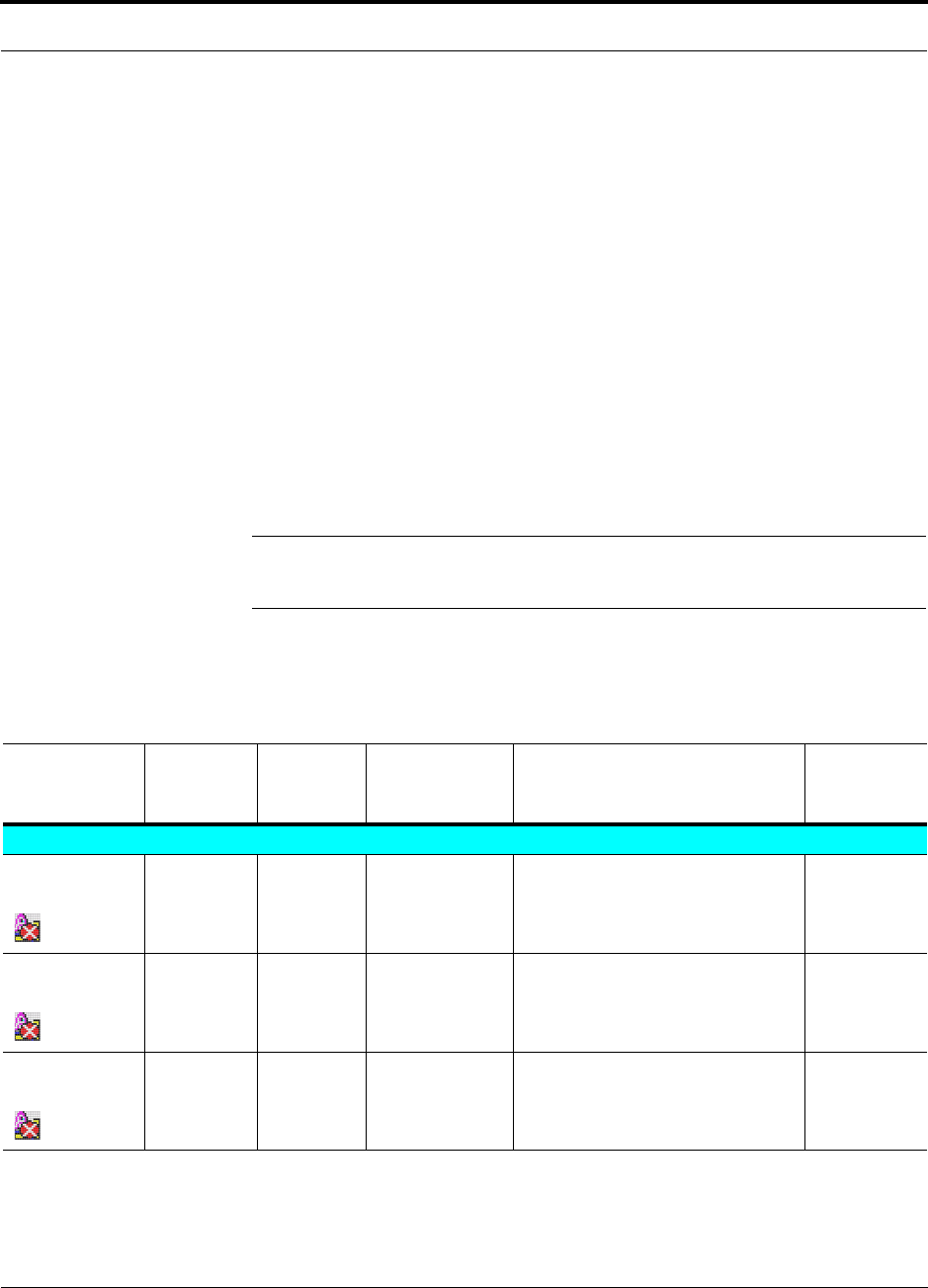
PN 9000-10 Help Hot Line (U.S. only): 1-800-530-9960 8-3
620021-0 Rev. A
8.3.1 Troubleshooting using AdminManager
To begin troubleshooting, use AdminManager software to determine the current
faults and warnings for all of the units in the system. To troubleshoot, start with the
Accel Hub’s faults and warnings, then proceed to each of the RAUs.
8.3.1.1 Fault Indications
Once all of the units are powered on and the cable connections are made, the faults
from each unit can be requested using AdminManager. Start with the Accel Hub and
work downstream.
Resolve all faults first and then check the warnings. Take appropriate action to
resolve the faults, as indicated in the following tables. In cases where there is more
than one possible cause, they are listed from the “most likely” to the “least likely”
cause. Actions are listed in the order that they should be performed; not all actions
may need to be done.
NOTE: If you have a red STATUS LED without a fault message, it probably
indicates that the unit is locked out.
Faults Reported by the Accel Hub
Table 8-1 Faults Reported by the Accel Hub
Fault
Message &
Icon LED State Possible
Causes Action Impact
Accel Hub Faults
Hardware
failure
STATUS Red Internal hard-
ware failure.
Replace the Hub. System
off-line.
Frequency band
not programmed
All LEDs
(except
POWER)
Continuous
blinking
Factory default. Program the frequency band using
AdminManager’s Installation Wiz-
ard.
System
off-line.
Failed to per-
form system test
STATUS Red Internal failure. Replace the Hub when possible. Degraded
performance.
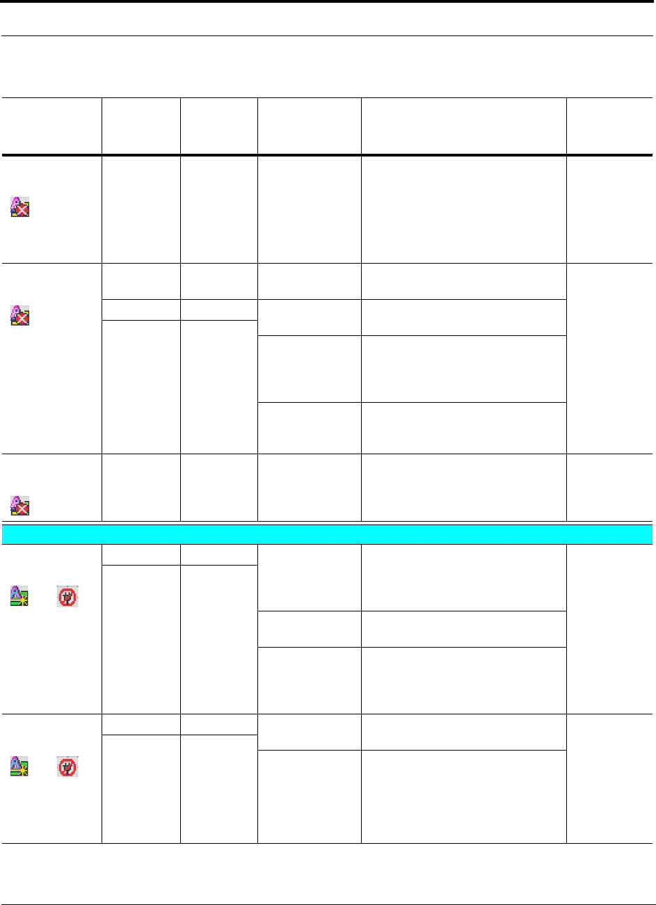
8-4 InterReach Unison Accel Installation, Operation, and Reference Manual PN 9000-10
620021-0 Rev. A
Accel is over
temperature
STATUS Red Fan failure Use AdminManager to check Hub
status.
Check the Hub fan for rotation, air
flow blockage, dust.
If fan is not operating, replace the
Hub.
Hub and con-
nected RAUs
off-line.
RAUn uplink
AGC failure
LINK Green Cat-5/6 cable
length.
Check Cat-5/6 cable length. Degraded
performance.
RAU Green Cat-5/6 cable
failure.
Check Cat-5/6 cable for shorts or
opens.
STATUS Red
Hub uplink port
failure or RAU
failure.
Move RAU to another port. If fault
persists, replace the RAU. If no fault,
flag previous port as unusable and
replace the Hub when possible.
Hub internal fail-
ure.
If more than one RAU connected to
the same Hub reports this failure,
replace the Hub.
RAUn downlink
port failure
STATUS Red Hub internal fail-
ure.
Move the RAU to another port. If
fault persists, replace the Hub. If no
fault, flag previous port as unusable
and replace the Hub when possible.
Degraded
performance.
RAU Faults
RAUn discon-
nected
and
LINK Red RAU was con-
nected and is
now discon-
nected.
If RAUn is disconnected, reconnect it
or use AdminManager’s “Clear All
Disconnect Status” command to clear
the disconnect fault.
RAUn is
off-line.
RAU Off
Cat-5/6 cable
failure.
Check Cat-5/6 cable for shorts or
opens.
RAU internal
failure or Accel
Hub port bad.
Move the RAU to another port. If
fault persists, replace the RAU. If no
fault, flag previous port as unusable
and replace the Hub when possible.
No communica-
tion with RAUn
and
LINK Red Cat-5/6 cable
failure.
Verify that the Cat-5/6 cable has no
shorts or opens.
Degraded
performance
or RAUn is
off-line.
RAU Off
RAU internal
failure.
or
Accel Hub port
failure.
Move the RAU cables to another
port. If fault persists, replace the
RAU; otherwise, the Hub port is bad,
mark the port as unusable and replace
the Hub when possible.
Table 8-1 Faults Reported by the Accel Hub (continued)
Fault
Message &
Icon LED State Possible
Causes Action Impact

PN 9000-10 Help Hot Line (U.S. only): 1-800-530-9960 8-5
620021-0 Rev. A
RAUn over
current
and
LINK Green Cat-5/6 cable
failure.
Verify Cat-5/6 cable has no shorts or
opens.
RAUn is
off-line.
RAU Red
RAU internal
failure.
Move RAU to another port. If fault
persists, replace the RAU. If no fault
reported, remove the RAU, power
cycle the Hub, connect known good
RAU to port. If fault reported, replace
the Hub.
Table 8-1 Faults Reported by the Accel Hub (continued)
Fault
Message &
Icon LED State Possible
Causes Action Impact

8-6 InterReach Unison Accel Installation, Operation, and Reference Manual PN 9000-10
620021-0 Rev. A
Remote Access Unit Faults
Table 8-2 Remote Access Unit Faults
Fault Message LED State Possible Causes Action Impact
Hardware failure ALARM Red Internal hardware failure. Replace the RAU. RAU is off-line.
Frequency band
not programmed
ALARM Red Wrong version of RAU for
frequency band desired.
Replace the RAU if not valid
for desired frequency band.
RAU is off-line.
RAU is over
temperature
ALARM Red Ambient temperature
above maximum.
Check environmental controls;
move the RAU to cooler envi-
ronment.
RAU is off-line.
Power supplied
by Accel Hub is
too low
ALARM Red Cat-5/6 cable failure. Verify Cat-5/6 cable has no
shorts or opens.
RAU is off-line.
RAU internal failure.
or
Accel Hub port failure.
Move the RAU cable to another
Hub port. If fault persists,
replace the RAU; otherwise,
the Hub port is bad, mark the
port as unusable and replace the
Hub when possible.
Accel Hub internal failure. If more than one RAU con-
nected to the same Hub reports
this failure, replace the Hub.
Downlink pilot
failure
ALARM Red Cat-5/6 cable failure. Verify that the Cat-5/6 cable
has no shorts or opens.
Verify maximum Cat-5/6 cable
length of 150 meters.
Verify minimum Cat-5/6 cable
length of 10 meters.
Degraded perfor-
mance or RAU is
off-line.
RAU internal failure.
or
Accel Hub port failure.
Move the RAU cable to another
Hub port. If fault persists,
replace the RAU; otherwise,
the Hub port is bad, mark the
port as unusable and replace the
Hub when possible.
Accel Hub internal failure. If more than one RAU con-
nected to the same Hub reports
this failure, replace the Hub.
PN 9000-10 Help Hot Line (U.S. only): 1-800-530-9960 8-7
620021-0 Rev. A
8.3.1.2 Warning Indications
Warnings alert you to conditions that indicate potential system failure. Warnings are
displayed in the Messages pane in red lettering.
Before addressing warnings, ensure that all faults are resolved. Take appropriate
action to resolve the warnings, as indicated in the following tables.
Accel Hub Warnings
Remote Access Unit Warnings
Table 8-3 Accel Hub Warnings
Warning Message Action Impact
Temperature is high Check room environmental controls. Potential Hub failure.
Input signal above lim-
iter
Reduce input signal strength. Can only occur for DCS, GSM, or UMTS configurations
Table 8-4 Remote Access Unit Warnings
Warning Message Action Impact
Temperature is high Move the RAU to cooler environment. Potential RAU failure.
Power amplifier is fail-
ing
Replace the RAU when possible. Potential RAU failure.
8-8 InterReach Unison Accel Installation, Operation, and Reference Manual PN 9000-10
620021-0 Rev. A
8.3.1.3 Status Messages
Status messages alert you to conditions that may impact system performance. Status
messages are displayed in the Messages pane in blue lettering.
NOTE: The icons displayed in the system status tree assume that there are
no other faults, warnings, or status present.
Accel Hub Status Messages
Table 8-5 Accel Hub Status Messages
Message Icon Action Impact
Commanded out of ser-
vice
Command unit into service using Admin-
Manager.
System is off-line.
Unable to perform sys-
tem test on power up
Check Hubs and RAUs for faults and
warnings.
Degraded system performance.
RAU reports a warning
status
Check RAUs for warnings. Degraded system performance.
Unable to perform sys-
tem end-to-end test
Replace Hub when possible. Degraded system performance.
Fann failure Check the Hub fans for rotation, air flow
blockage, dust
Use AdminManager to check Hub status.
If fans are not operating, replace the Hub.
Temperature may rise to fault level result-
ing in the Hub and connected RAUs being
off-line.
Cat-5/6 cable is longer
than recommended maxi-
mum
Check that the Cat-5/6 cable does not
exceed the recommended maximum
length.
Degraded system performance.
Commanded Fault Lock-
out
Use AdminManager to check Hub faults
and replace Hub as required.
Perform system test.
Connected RAUs are off-line.
PN 9000-10 Help Hot Line (U.S. only): 1-800-530-9960 8-9
620021-0 Rev. A
Remote Access Unit Status Messages
Table 8-6 Remote Access Unit Status Messages
Message Icon Action Impact
DC voltage is low Check the Cat-5/6 cable for shorts and
opens.
Replace the RAU when possible.
Unreliable operation.
Cat-5/6 cable is longer
than recommended maxi-
mum
Check that the Cat-5/6 cable does not
exceed the recommended maximum
length.
Degraded system performance.
Unit not system tested Use AdminManager to command System
Test. Note that the system will be off-line
for 30 seconds during test.
System not operating at optimum perfor-
mance.
Antenna disconnected Check that the antenna is connected to the
RAU; check coax cable between RAU
and antenna.
Antenna may be disconnected. If it is con-
nected, then the antenna/cable measure
higher return loss than optimum configu-
ration.
RAU Commanded
Out-of-Service
Command unit into service using Admin-
Manager.
RAU is off-line.
Commanded Fault Lock-
out
Use AdminManager to check Hub faults
and and replace Hub as required.
RAU is off-line.
Power supplied by Accel
Hub is too high
Check the Cat-5/6 cable for opens and
shorts.
Move RAU cable to another Hub port.
Replace RAU when possible.
Unreliable operation.
System test uplink failure Unable to complete system test. Degraded system performance.
Can’t calibrate downlink Unable to complete system test. Degraded system performance.

8-10 InterReach Unison Accel Installation, Operation, and Reference Manual PN 9000-10
620021-0 Rev. A
8.3.2 Troubleshooting using LEDs
The following troubleshooting guide is from the perspective that all Unison Accel
equipment is installed, their cables are connected, and they are powered on; it is
assumed that the system was operating normally before the problem to be diagnosed
occurred. (Refer to Section 6 for information on troubleshooting during initial instal-
lation of the system.)
Always use AdminManager, if possible, to troubleshoot the system. The Hub LEDs
are for backup troubleshooting. The RAU LEDs probably will not provide additional
information for troubleshooting.

PN 9000-10 Help Hot Line (U.S. only): 1-800-530-9960 8-11
620021-0 Rev. A
8.3.2.1 Troubleshooting Accel Hub LEDs During Normal Operation
• All of the Accel Hub’s LINK and RAU LEDs that have RAUs connected should be
Green/Green, indicating that the RAU is powered on, communication is estab-
lished, and operation is normal.
•The
POWER and STATUS LEDs should all be Green.
Table 8-7 Troubleshooting Accel Hub Port LEDs During Normal Operation
During
Normal
Operation Accel Hub
Port LEDs State Action Impact
RAU is not
connected
LINK Red If the RAU was disconnected acci-
dentally, re-connect the Cat-5/6
cable. The Hub’s port LEDs should
change to Green/Red (then
Green/Green, after 20 seconds, if the
Hub is connected and has band pro-
grammed).
Use AdminManager to calibrate sys-
tem when possible to achieve the
best performance.
Use AdminManager’s “Clear All
Disconnect Status” command if you
are permanently removing the RAU
from service. The Hub’s port LEDs
should change to Off/Off.
RAU was previously connected, but it
is not currently connected; RAU cable
is disconnected.
RAU Off
RAU is
connected
LINK Red Disconnect/reconnect the Cat-5/6
cable to force power-on reset to the
RAU. If the port LEDs remain
Red/Off, check for the exact cause of
Hub faults using AdminManager.
Lost communications with the RAU.
The RAU could have powered down
due to over current; cable could have
been damaged.
RAU Off
LINK Green RAU reports a fault condition; check
for the exact cause of Hub and RAU
faults using AdminManager.
Depends on the fault condition.
RAU Red

8-12 InterReach Unison Accel Installation, Operation, and Reference Manual PN 9000-10
620021-0 Rev. A
Table 8-8 Troubleshooting Accel Hub Status LEDs During Normal Operation
During
Normal
Operation
Accel Hub
Status
LEDs State Action Impact
At Any
Time
STATUS Red Use AdminManager to determine the
exact cause of the fault.
Power cycle one time. If fault
remains, replace the Hub.
Internal Hub fault.
Use AdminManager to check if the
Hub is commanded Out-of-Service
(every Hub PORT LED will be red
as well).
A power cycle will not clear a com-
manded Out-of-Serivce, you must
use AdminManager to clear this
state.
Main Hub and all downstream units are
off-line.
STATUS Alternating
Red/Green
Reduce input signal power; reduce
system gain.
Signal compression.
PN 9000-10 Help Hot Line (U.S. only): 1-800-530-9960 8-13
620021-0 Rev. A
8.4 Troublshooting Cat-5/6
Refer to Table A-1 on page A-1 for a description of the Cat-5/6 wire assignments.
The following table summarizes Cat-5/6 problems if a wire is cut or miswired.
Table 8-9 Summary of Cat-5/6 Cable Wiring Problems
Type of
problem Message Icon Impact
Wire 1 or 2 cut None High phase noise, degraded signal on both
Downlink and Uplink (high bit error rate)
Wire 3 or 6 cut • No communication with RAUn RAU unable to communicate with Hub,
degraded performance or RAU off-line
Wire 4 or 5 cut • RAUn uplink AGC failure Increased ripple in the uplink path,
decreased UL gain, or no UL gain
• Cat-5/6 cable between RAUn and Hub is
longer than recommended
Wire 7 or 8 cut • Downlink pilot failure Increased ripple in the downlink path,
RAU off-line
• Cat-5/6 cable between RAUn and Hub is
longer than recommended
Wire 1 to RJ-45
pin 3 or 6
• No communication with RAUn RAU unable to communicate with Hub,
RAU’s RS-485 port damaged, degraded
performance or RAU off-line
Wire 1 to RJ-45
pin 4, 5, 7 or 8
•RAUn over current RAU will not power on.
Wire 2 to RJ-45
pin 3 or 6
• No communication with RAUnRAU unable to communicate with Hub,
RAU’s RS-485 port damaged, degraded
performance or RAU off-line
Wire 2 to RJ-45
pin 4, 5, 7 or 8
•RAUn over current RAU will not power on
Wire 3 to RJ-45
pin 4, 5, 7 or 8
• No communication with RAUnRAU unable to communicate with Hub,
degraded performance or RAU off-line
Wire 6 to RJ-45
pin 4, 5, 7 or 8
• No communication with RAUnRAU unable to communicate with Hub,
degraded performance or RAU off-line
Wire 4 to RJ-45
pin 7 or 8
•RAUn uplink AGC failure Increased ripple in the downlink and
uplink path, degraded performance or
RAU off-line
• Downlink pilot failure
• Cat-5/6 cable between RAUn and Hub is
longer than recommended
8-14 InterReach Unison Accel Installation, Operation, and Reference Manual PN 9000-10
620021-0 Rev. A
Wire 5 to RJ-45
pin 7 or 8
•RAUn uplink AGC failure Increased ripple in the downlink and
uplink path, degraded performance or
RAU off-line
• Cat-5/6 cable between RAUn and Hub is
longer than recommended
• Downlink pilot failure
• Cat-5/6 cable between RAUn and Hub is
longer than recommended
Table 8-9 Summary of Cat-5/6 Cable Wiring Problems (continued)
Type of
problem Message Icon Impact

PN 9000-10 Help Hot Line (U.S. only): 1-800-530-9960 8-15
620021-0 Rev. A
8.5 Technical Assistance
Call our help hot line for technical assistance:
1-800-530-9960 (U.S. only)
+1-408-952-2400 (International)
Leave your name and phone number and an LGC Wireless customer service repre-
sentative will return your call within an hour. Be prepared to provide the following
information when you receive the return call:
• Company name
• End user name
• Type of system, model number, frequency
• Approximate time in service (warranty), sales order number
• Description of problem
• LED status
• AdminManager faults, warnings, and status messages

8-16 InterReach Unison Accel Installation, Operation, and Reference Manual PN 9000-10
620021-0 Rev. A

PN 9000-10 InterReach Unison Accel Installation, Operation, and Reference Manual A-1
620021-0 Rev. A
APPENDIX A Cables and Connectors
A.1 Cat-5/6 Cable (ScTP)
• Connects the Accel Hub to the RAU(s)
• Transmits (downlink) and receives (uplink) IF signals
• Delivers DC electrical power to the RAUs. The Accel Hub’s DC voltage output is
36V DC nominal. A current limiting circuit is used to protect the Hub if it reaches
its current limit
• Carries configuration and status information
• Use shielded RJ-45 connectors
• Distances:
• Minimum: 10 meters (33 ft)
• Recommended Maximum: 100 meters (328 ft)
• Absolute Maximum: 150 meters (492 ft)
There are four separate twisted pairs in one Cat-5/6 screened twisted pair (ScTP)
cable. The ScTP cable loss described in this document is for Cat-5 Mohawk/CDT
55986 or Belden 1624P DataTwist Five cable, or equivalent. The following table lists
the functional assignment of the pairs:
Table A-1 Cat-5/6 Twisted Pair Assignment
Pair (wire number) Function
1 & 2 Clock and Input Voltage
3 & 6 RS-485
4 & 5 Uplink IF, UL Pilot and Ground
7 & 8 Downlink IF, DL Pilot and Ground
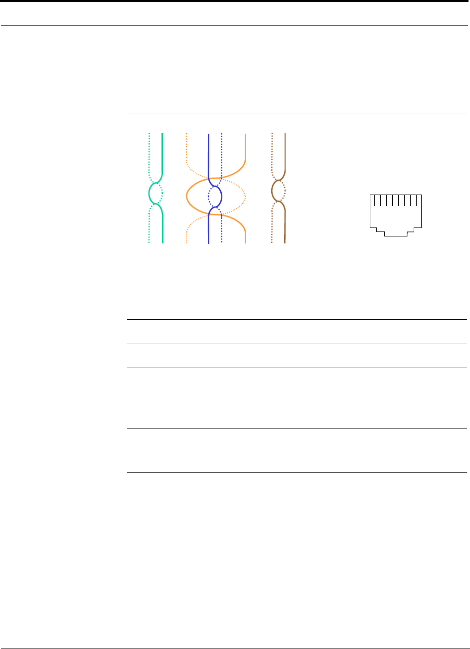
A-2 InterReach Unison Accel Installation, Operation, and Reference Manual PN 9000-10
620021-0 Rev. A
All Cat-5/6 cable must be terminated according to the TIA/EIA 568-A standard. The
following diagram shows the top view of the wiring map for the cable and how the
four pairs should be terminated.
Figure A-1 Wiring Map for Cat-5/6 Cable
The nominal DC impedance of the Cat-5/6 cable is 0.08 ohm/meter and the nominal
RF impedance is 100 ohm.
NOTE: Be sure to test cable termination before installing the cable.
NOTE: Mohawk/CDT 55986 or Belden 1624P DataTwist® Five ScTP cable, or
equivalent is required. In order to meet FCC and CE Mark emissions requirements,
the Cat-5/6 cable must be screened (ScTP) and it must be grounded to the units at
both ends using shielded RJ-45 connectors.
A.2 Coaxial Cable
• Connects an Accel Hub to a repeater or base station (N-type connectors)
• Connects an RAU to a passive antenna (SMA connectors)
12 3 45 6 78
Brown
Brown/
White
Blue Blue/
White
Green/
White
Green Orange
Orange/
White
RJ-45 Port
12345678
W-G
G
W-O
BL
W-BL
O
W-BR
BR
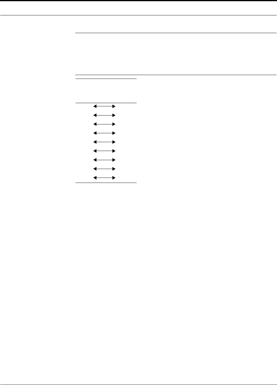
PN 9000-10 Help Hot Line (U.S. only): 1-800-530-9960 A-3
620021-0 Rev. A
A.3 Standard Modem Cable
• Connects a modem to the Accel Hub’s front panel serial port
Figure A-2 Standard Modem Cable Pinout
DB-9
Connector
Pin
DB-25
Connector
Pin
1
2
3
4
5
6
7
8
9
8
3
2
20
7
6
4
5
22
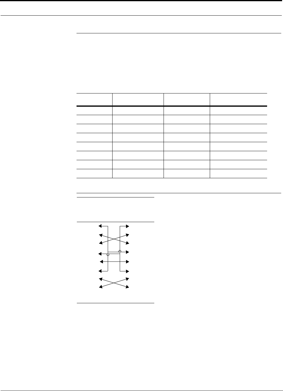
A-4 InterReach Unison Accel Installation, Operation, and Reference Manual PN 9000-10
620021-0 Rev. A
A.4 DB-9 to DB-9 Null Modem Cable
A DB-9 female to DB-9 female null modem cable is used to connect the AdminMan-
ager PC to an Accel Hub. A cable is included with AdminManager. Table A-2 lists
the cable pinout and Figure A-3 shows a diagram of its wiring.
Figure A-3 DB-9 Female to DB-9 Female Null Modem Cable Diagram
Table A-2 DB-9 Female to DB-9 Female Null Modem Cable Pinout
From Signal To Signal
P1-4 DTR P2-6, P2-1 DSR, DCD
P1-6 DSR P1-1, P2-4 DCD, DTR
P1-3 TXD P2-2 RXD
P1-2 RXD P2-3 TXD
P1-5 GND P2-5 GND
P1-7 RTS P2-8 CTS
P1-8 CTS P2-7 RTS
P1-9 N/C N/C N/C
Note that for each DB-9 connector, pins 1 and 6 are tied together and sent to pin 4
of the opposite connector; thus, providing the required handshake signals.
DB-9
Connector
Pin
DB-9
Connector
Pin
1
2
3
4
5
6
7
8
9
1
2
3
4
5
6
7
8
9
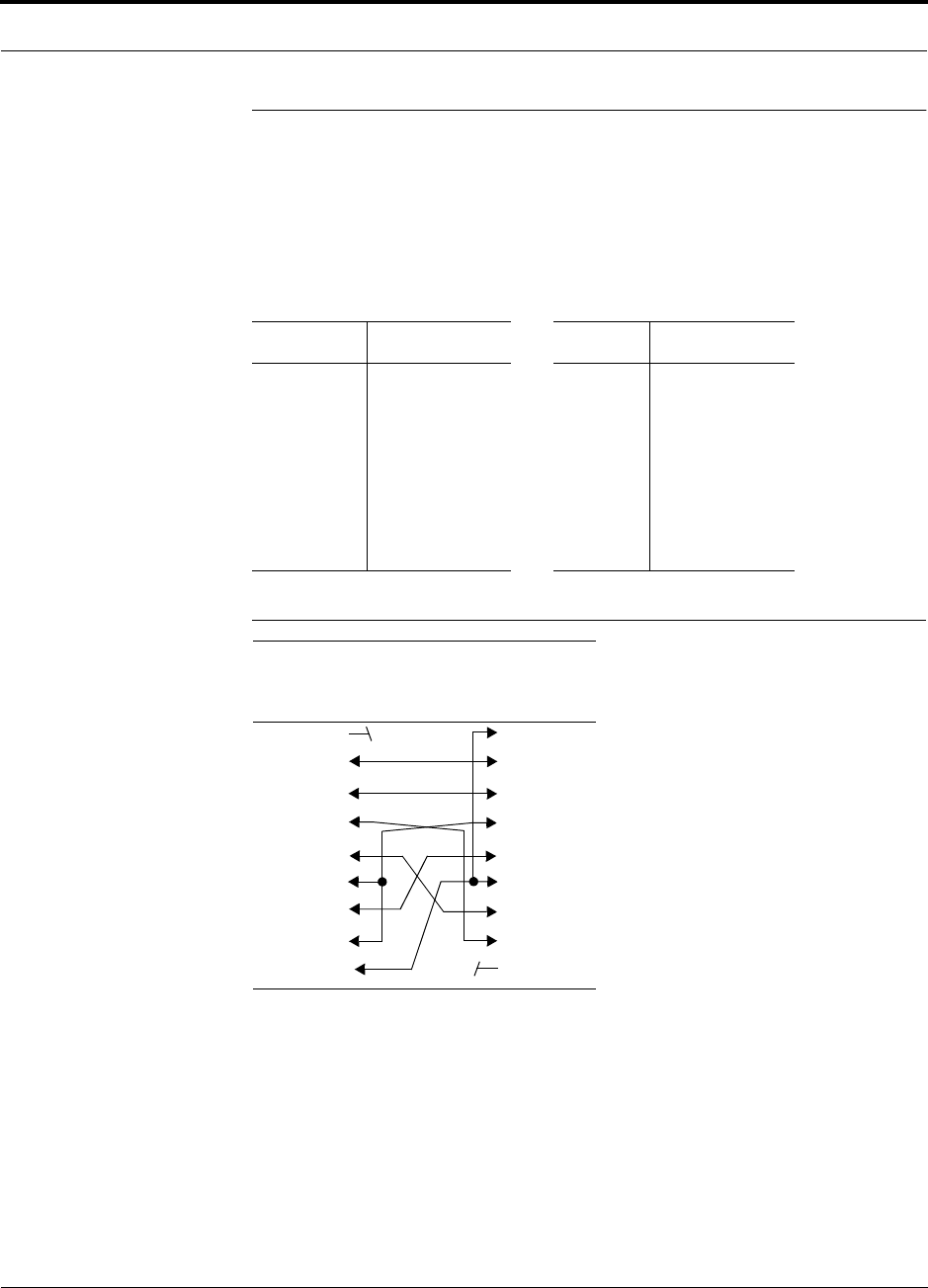
PN 9000-10 Help Hot Line (U.S. only): 1-800-530-9960 A-5
620021-0 Rev. A
A.5 DB-25 to DB-9 Null Modem Cable
A DB-25 male to DB-9 female Null modem cable is used to connect a 232 Port
Expander to an Accel Hub. Table A-3 lists the pinout of the cable and Figure A-4
shows a diagram of its wiring.
Figure A-4 DB-25 Male to DB-9 Female Null Modem Modem Cable Diagram
Table A-3 DB-25 Male to DB-9 Female Null Modem Cable Pinout
25-Pin Signal 9-Pin Signal
20
2
3
6,8
7
5
4
DTR
TX
RX
DSR, DCD
GND
CTS
RTS
1, 6
2
3
4
5
7
8
DSR, DCD
RX
TX
DTR
GND
RTS
CTS
DB-25 Male
Connector
Pin
DB-9 Female
Connector
Pin
1
2
3
4
5
6
7
8
20
1
2
3
4
5
6
7
8
9

A-6 InterReach Unison Accel Installation, Operation, and Reference Manual PN 9000-10
620021-0 Rev. A
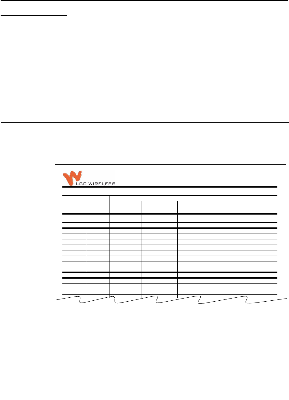
PN 9000-10 InterReach Unison Accel Installation, Operation, and Reference Manual B-1
620021-0 Rev. A
APPENDIX B InterReach Unison Accel
Property Sheet
Use the InterReach Unison Accel Property Sheet, which is provided on the following
page, to document a system configuration. The completed form can be used for future
reference when the system is being maintained or components are added or
exchanged. An example of a completed form is shown below.
InterReach Unison Accel Property Sheet
Installer:
J. Smith Date:
10/10/02 Accel Hub Serial Number:
L010BMH1
System Label: System Gain: Alarm Sense: System Band:
DCS 2
AB UL: DL: Yes
No
Normally-Closed
Normally-Open
Unit
HUB - RAU
RAU Attenuation?
Yes/No
RAU
Serial No. RAU Installation Location
AB-1-n — L010BEH9 2nd floor Telecom closet
AB-1 (RAU 1) no L010BRU1 Hallway, outside Boardroom
AB-2 (RAU 2) no L120BRU1 Hallway, outside #230
AB-3 (RAU 3) yes L007BRU1 Hallway, atrium north side
AB-4 (RAU 4) no L111BRU6 Hallway, outside #207
1-5 (RAU 5)
1-6 (RAU 6)
1-7 (RAU 7)
1-8 (RAU 8)
2-n —
2-1 (RAU 1)
2-2 (RAU 2)
2-3 (RAU 3)
2-4 (RAU 4)
2-5 (RAU 5)
2-6 (RAU 6)
1-2-7 (RAU 7)
1-2-8 (RAU 8)
1-3-n (EH 3) —
1-3-1 (RAU 1)
1-3-2 (RAU 2)
1-3-3 (RAU 3)
1-3-4 (RAU 4)
1-3-5 (RAU 5)
1-3-6 (RAU 6)
1-3-7 (RAU 7)
1-3-8 (RAU 8)
1-4-n (EH 4) —
1-4-1 (RAU 1)
1-4-2 (RAU 2)
1
-
4
-
3(RAU3)

B-2 InterReach Unison Accel Installation, Operation, and Reference Manual PN 9000-10
620021-0 Rev. A
InterReach Unison Accel Property Sheet
Installer: Date: Accel Hub Serial Number:
System Label: System Gain: Alarm Sense: System Band:
UL: DL: Yes
No
Normally-Closed
Normally-Open
Unit
HUB - RAU
RAU
Attenuation?
Yes/No
RAU
Serial No. RAU Installation Location
1-n
1-1 (RAU 1)
1-2 (RAU 2)
1-3 (RAU 3)
1-4 (RAU 4)
1-5 (RAU 5)
1-6 (RAU 6)
1-7 (RAU 7)
1-8 (RAU 8)
2-n
2-1 (RAU 1)
2-2 (RAU 2)
2-3 (RAU 3)
2-4 (RAU 4)
2-5 (RAU 5)
2-6 (RAU 6)
2-7 (RAU 7)
2-8 (RAU 8)
3-n
3-1 (RAU 1)
3-2 (RAU 2)
3-3 (RAU 3)
3-4 (RAU 4)
3-5 (RAU 5)
3-6 (RAU 6)
3-7 (RAU 7)
3-8 (RAU 8)
4-n
4-1 (RAU 1)
4-2 (RAU 2)
4-3 (RAU 3)
4-4 (RAU 4)
4-5 (RAU 5)
4-6 (RAU 6)
4-7 (RAU 7)
4-8 (RAU 8)

PN 9000-10 InterReach Unison Accel Installation, Operation, and Reference Manual C-1
620021-0 Rev. A
APPENDIX C Compliance
C.1 Unison System Approval Status
900 Paging/SMR
• Safety: UL 60950 3rd Edition
• EMC: FCC part 15 class A
• Radio: FCC Part 90
Cellular Products
• Safety: UL 60950 3rd Edition
• EMC: FCC part 15 class A
• Radio: FCC Part 22
DCS Products
• Safety: CB scheme evaluation to IEC 950, 3rd Edition with all national deviations
• EMC: EN 301 489-8 V.1.1.1 (2000-09), CISPR 24: 1998
• Radio: ETS 300 609-4 V.8.0.2 (2000-10)
GSM/EGSM Products
• Safety: CB scheme evaluation to IEC 950, 3rd Edition with all national deviations
• Radio: EN 301 502 V.7.0.1 (2000-08)
• EMC: EN 301 489-8 V.1.1.1 (2000-09), CISPR 24: 1998

C-2 InterReach Unison Accel Installation, Operation, and Reference Manual PN 9000-10
620021-0 Rev. A
iDEN Products
• Safety: UL 60950, 3rd Edition
• EMC: FCC part 15 class A
•Radio: FCC part 90
PCS Products
• Safety: UL 60950 3rd Edition
• EMC: FCC part 15 class A
•Radio: FCC part 24
UMTS Products
• Safety: CB scheme evaluation to IEC 950, 3rd Edition with all national deviations
• EMC: ETSI TS 125 113 V.4.1.0 (2001-06)
• Radio: ETSI TS 125 143 V.4.0.0 (2001-03)
Note for Canadian customers: The Manufacturer’s rated output power1 of this equip-
ment is for single carrier operation. For situations when multiple carrier signals are
present, the rating would have to be reduced by 3.5 dB, especially where the output
signal is re-radiated and can cause interference to adjacent band users. This power
reduction is to be by means of input power or gain reduction and not by an attenuator
at the output of the device.
1. “Manufacturer’s rated output power” refers to Unison’s downlink P1dB. The power per carrier tables take into account this
power reduction for multiple carriers.

PN 9000-10 Help Hot Line (U.S. only): 1-800-530-9960 C-3
620021-0 Rev. A
C.2 Human Exposure to RF
The U.S. Federal Communications Commission (FCC) has adopted limits of human
exposure to radio frequency (RF) emissions from portable or fixed RF systems that
are regulated by the FCC. The exposure limits on the incident electric and magnetic
fields and power densities are based on ANSI/IEEE and NCRP RF Safety Guidelines.
The limits are also prescribed in terms of the mass-normalized rates of internal energy
absorption by tissues (specific absorption rates or SARs) which should not exceed
0.08 W/kg as averaged over the whole body and 1.6 W/kg for any 1-g of tissue.
Similarly, the U.K. National Radiological Protection Board (NRPB) and the Interna-
tional Commission on Non-Ionizing Radiation Protection (ICNIRP) have both estab-
lished guidelines for maximum RF exposure levels that are likely to not pose health
risks. For the general public, ICNIRP recommends maximum exposure levels of
2.0 W/kg for any 10-g of tissue. This recommendation is 5 times lower than that of
NRPB.
The specific absorption rate (SAR) was measured for a radiated power of 20 dBm
(100 mW) which is the maximum radiated for both of the antennas. The highest SAR
regions for each of the antennas for separation distances of 0, 1, 2, and 3 cm to the tis-
sue-simulant model were determined in the first instance by using a coarser sampling
with a step size of 8.0 mm over three overlapping scan areas for a total scan area of
8.0 × 9.6 cm. After identifying the regions of the highest SAR for each of the cases,
the SAR distributions were measured with a resolution of 2 mm in order to obtain the
peak 1 cm 3 or 1-g SAR.
Antenna gain is restricted to 1.5 W ERP (2.49 W EIRP) in order to satisfy RF expo-
sure compliance requirements. If higher than 1.5 W ERP, routine MPE evaulation is
needed. The antennas should be installed to provide at least 20 cm from all persons to
satisfy MPE requirements of FCC Part 2, 2.1091.

C-4 InterReach Unison Accel Installation, Operation, and Reference Manual PN 9000-10
620021-0 Rev. A

PN 9000-10 InterReach Unison Accel Installation, Operation, and Reference Manual D-1
620021-0 Rev. A
APPENDIX D Release Notes
D.1 Unison Accel Release 5
This document is for the Unison Accel products listed in the following table.
Table D-1 Unison Accel Release 5 Line-up
Unison Accel
Component Part
Number EPN* Hardware
Revision**
Firmware (FW) or
Software (SW)
Release*
Accel Hub UNS-ACCEL-1 740510-2 C 010559 (FW)
RAU:
PCS UNS-PCS-2 740552-2 C 01053C (FW)
DCS UNS-DCS-1 740553-1 D 01053C (FW)
GSM UNS-GSM-1 740554-1 E 01052B (FW)
Cellular UNS-CELL-1 740550-1 B 01052B (FW)
iDEN UNS-IDEN-1 740551-0 A 01052B (FW)
UMTS UNS-UMTS-1 740560-1 B 01052B (FW)
AdminManager SW-ADM-V2 750001-0 N/A v2.0 (SW)
* Use the Get Unit Info command in the AdminManager’s Configuration & Maintenance Panel to
verify the EPN and Firmware/Software Version of the component
** The hardware revision number is on a label on the back panel of the component

D-2 InterReach Unison Accel Installation, Operation, and Reference Manual PN 9000-10
620021-0 Rev. A