ADC Telecommunications UNS-PS70-1 In-Building Wireless Networking System User Manual unison
ADC Telecommunications Inc. In-Building Wireless Networking System unison
UserManual.wiki
>
ADC Telecommunications
>
UNS PS70 1 User Manual
User Manual
Navigation menu
Upload a User Manual
Namespaces
Wiki Guide
HTML
PDF
Info
Views
User Manual
Discussion / Help
Navigation


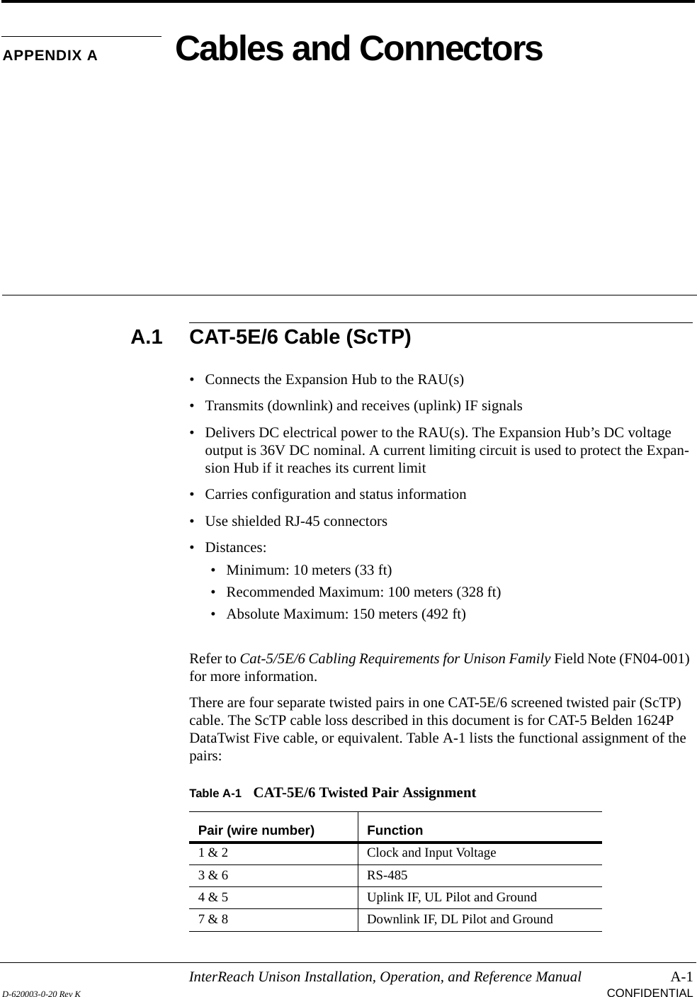
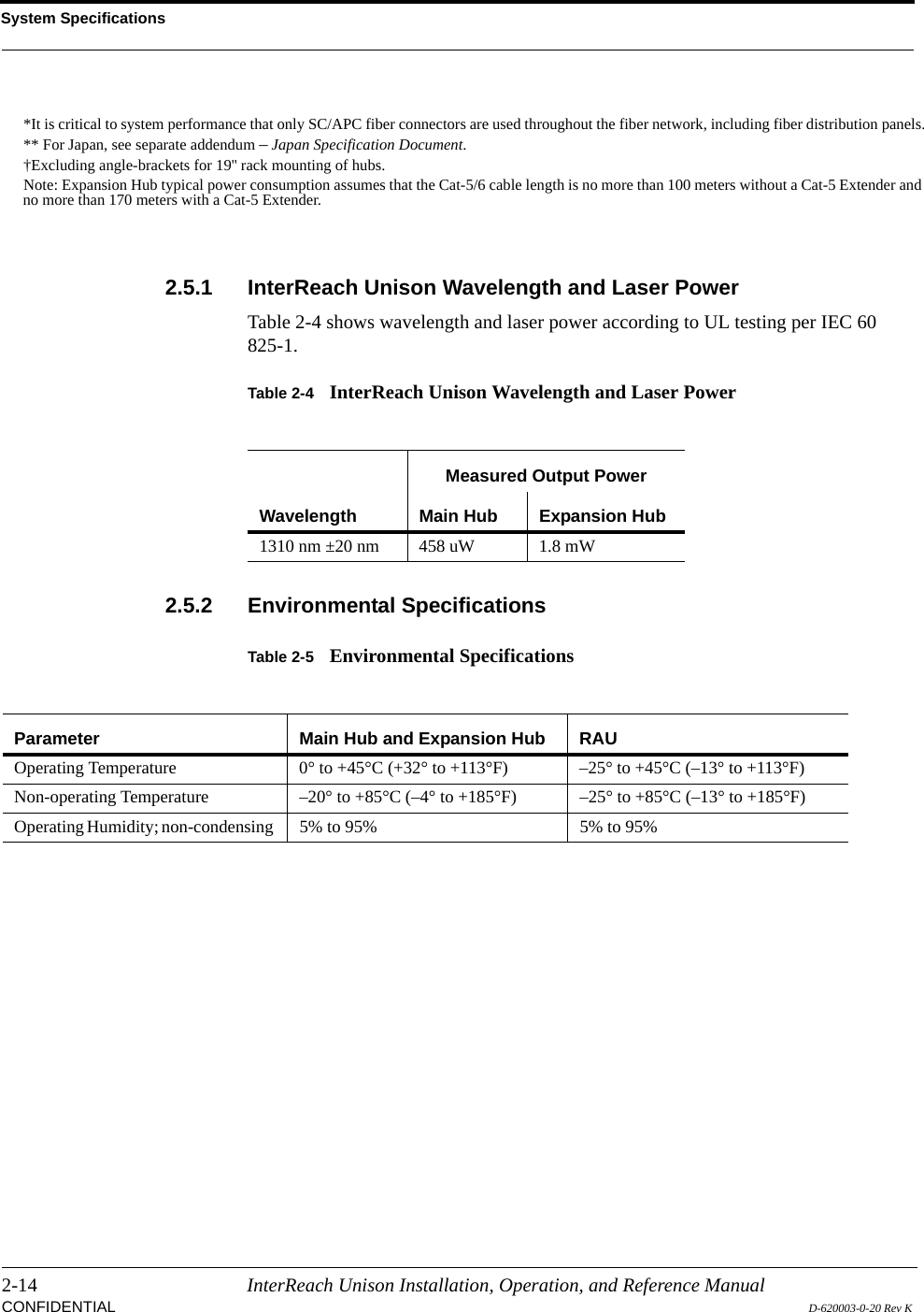
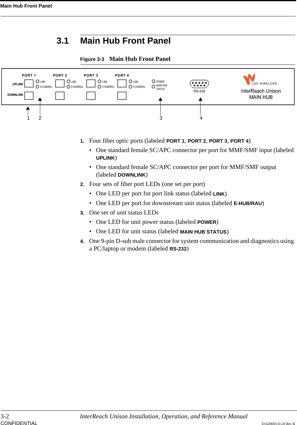
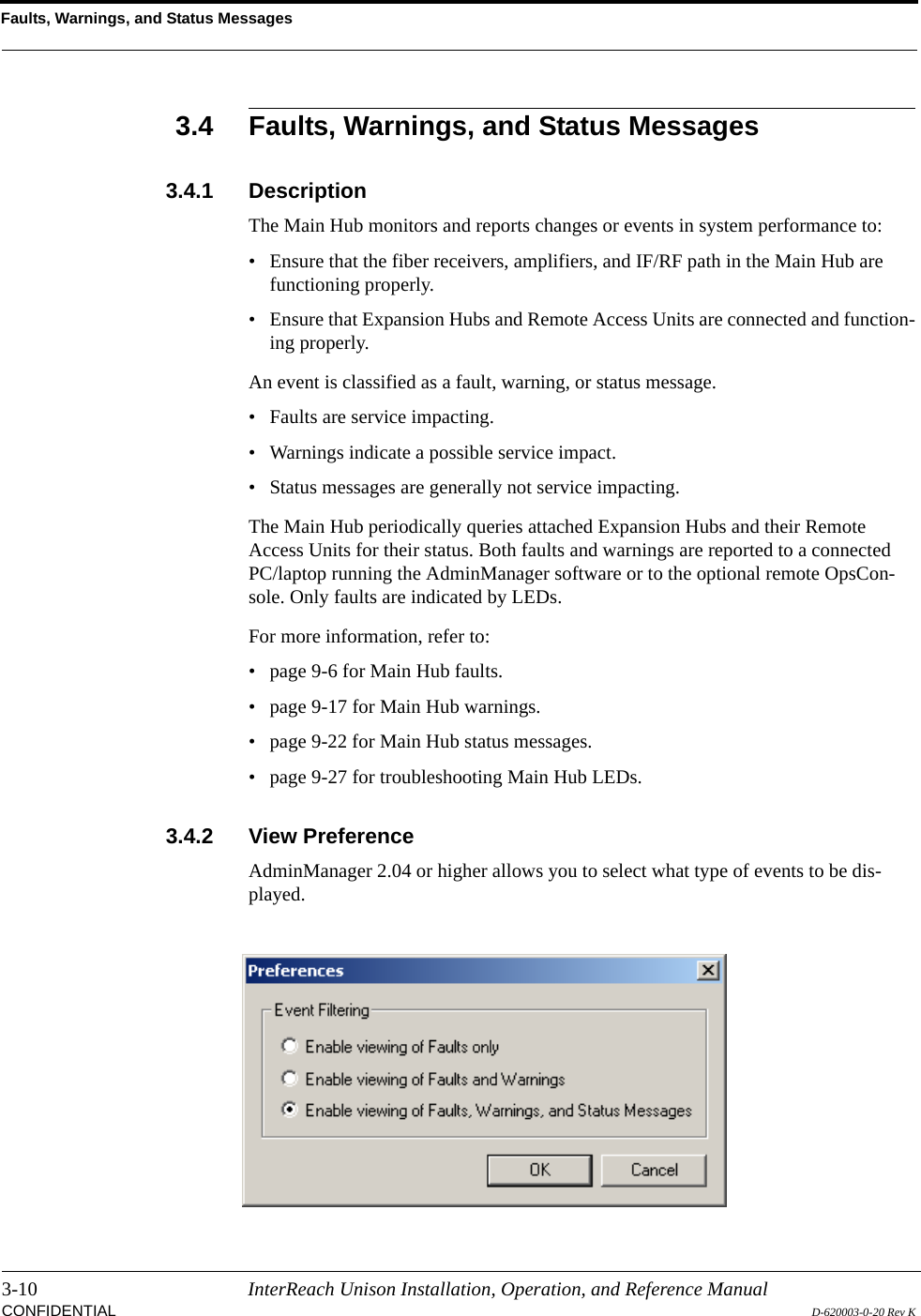
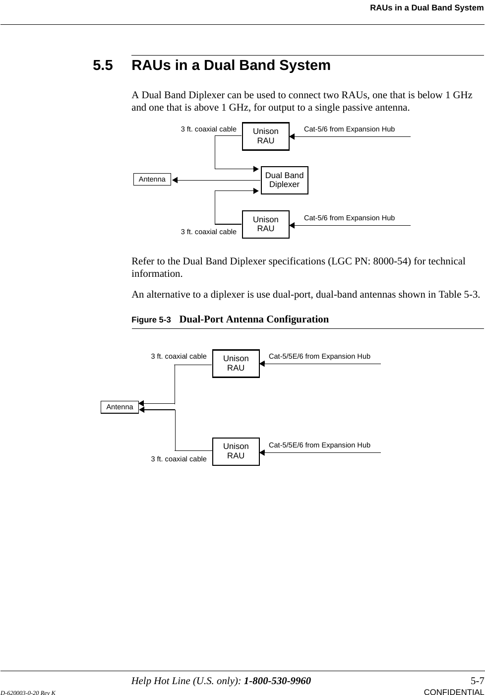
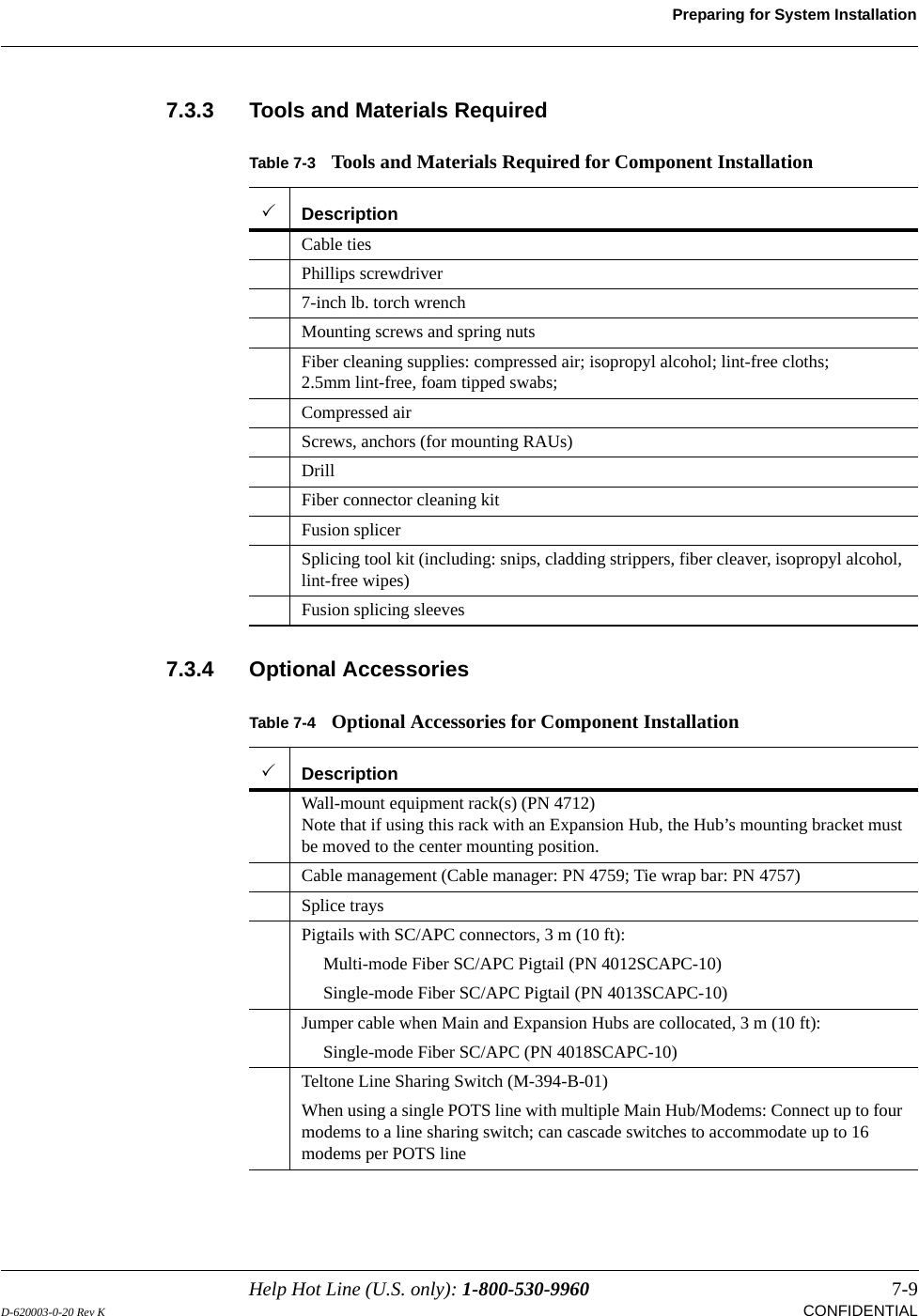
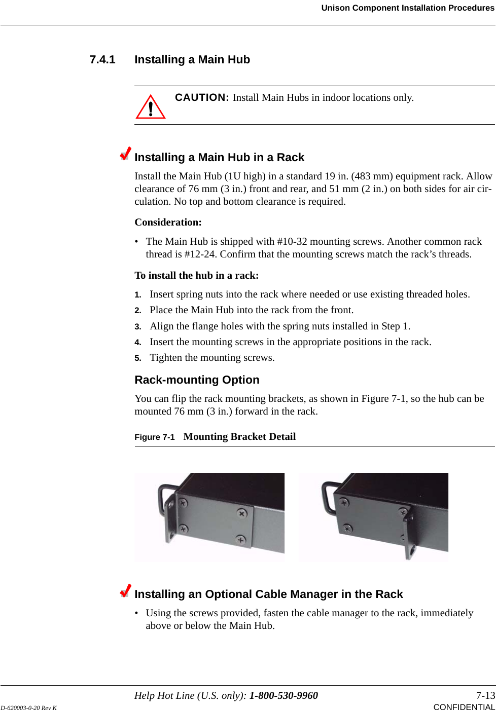
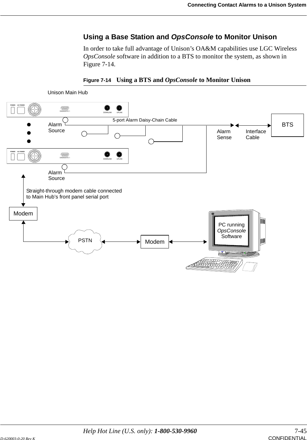
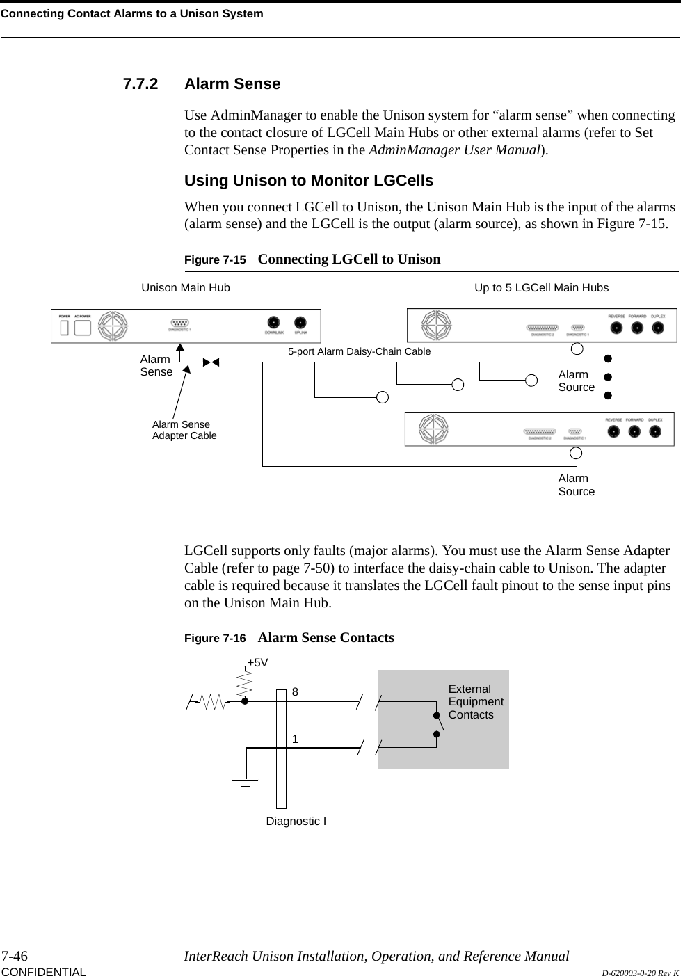
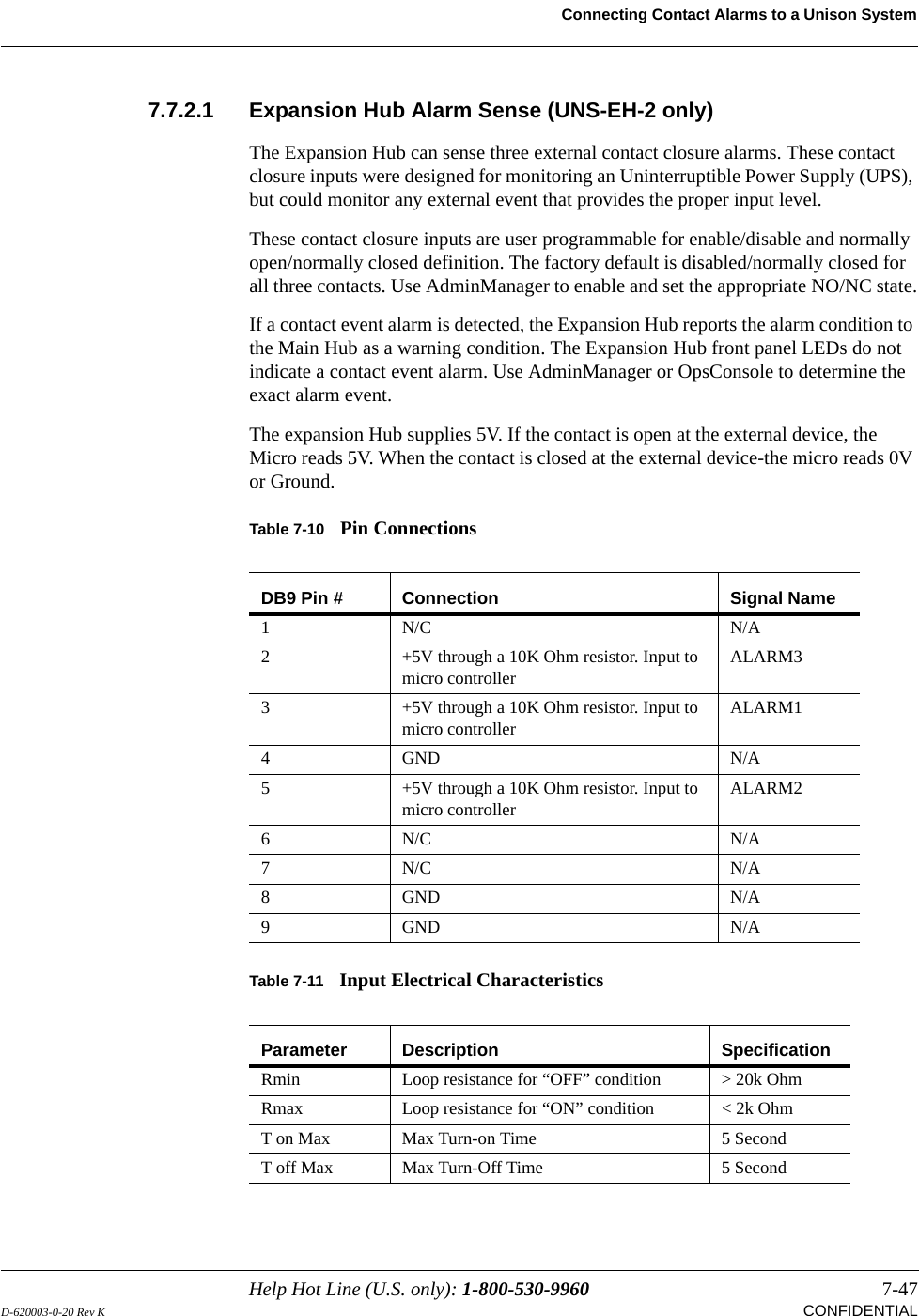
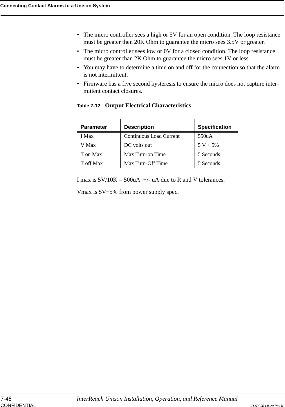
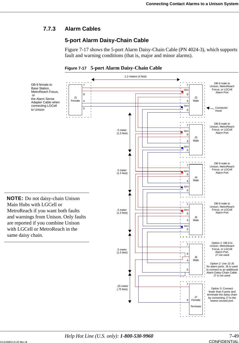
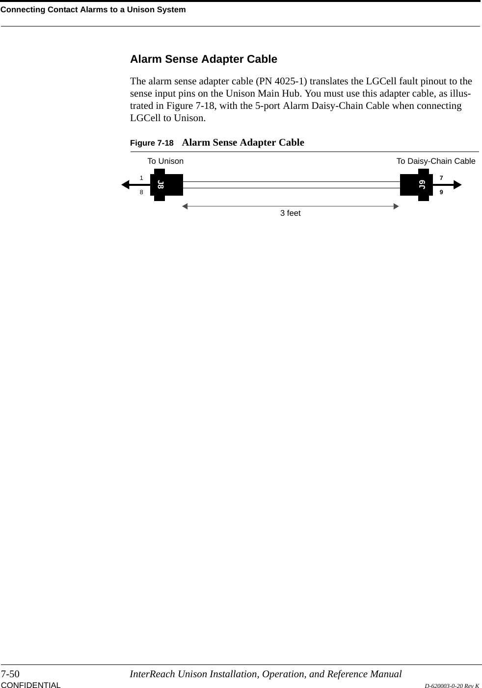
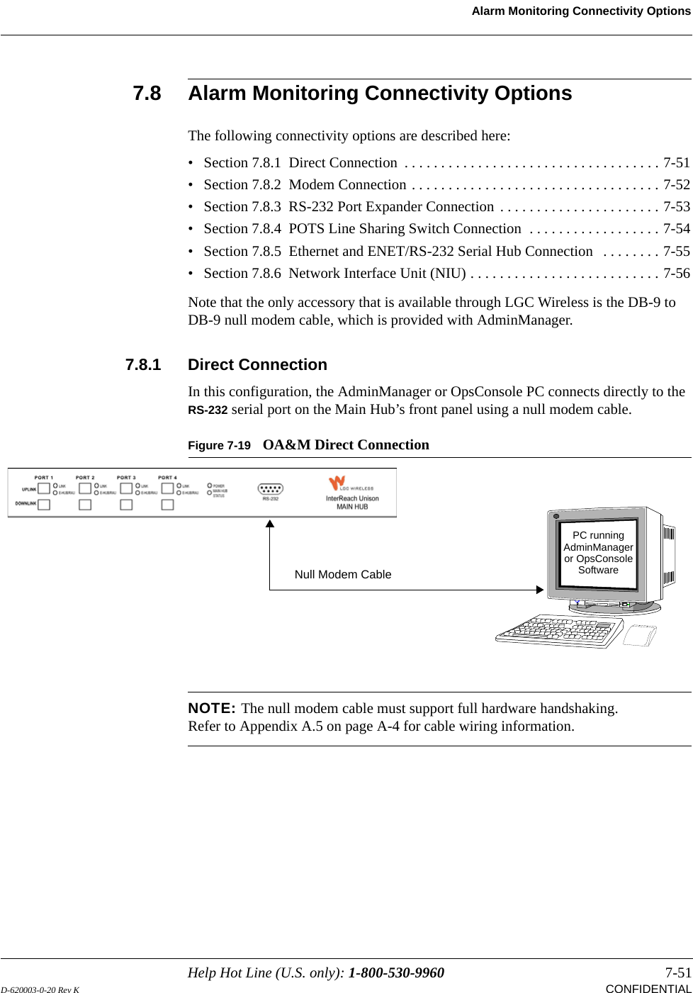
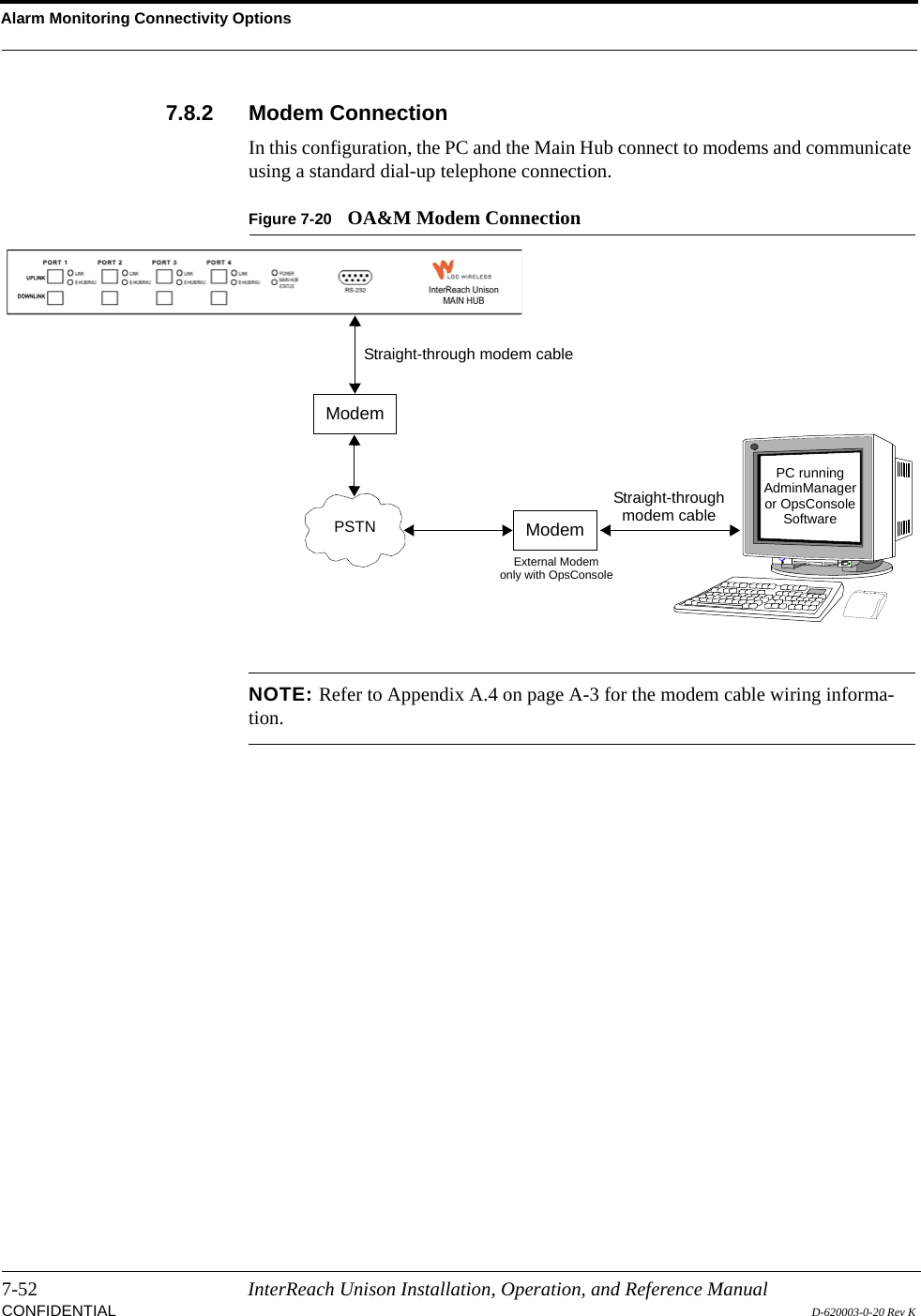
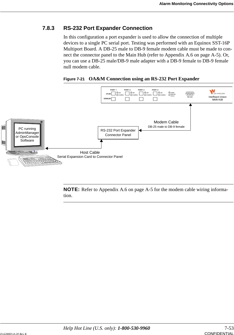
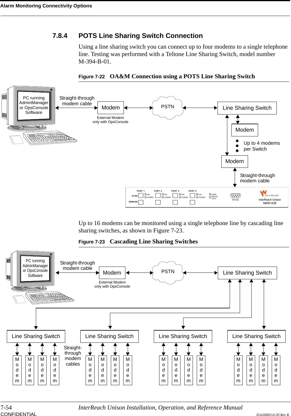
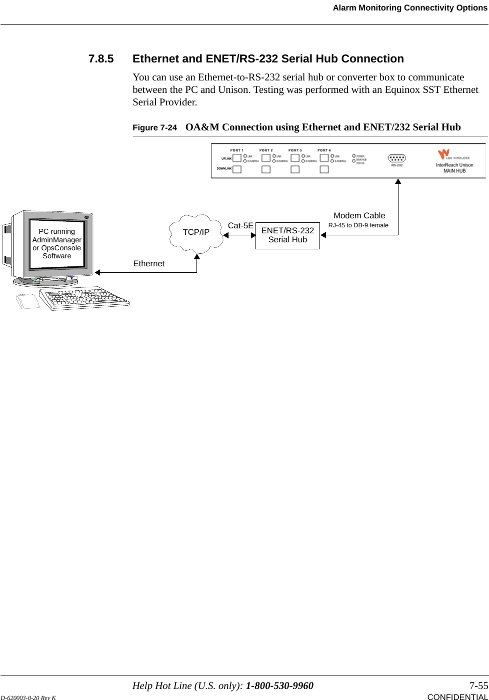
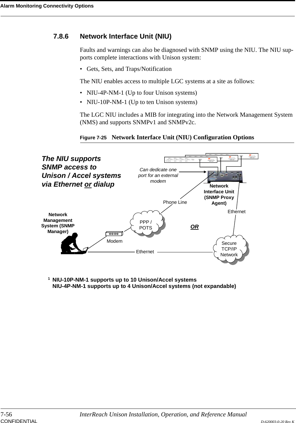
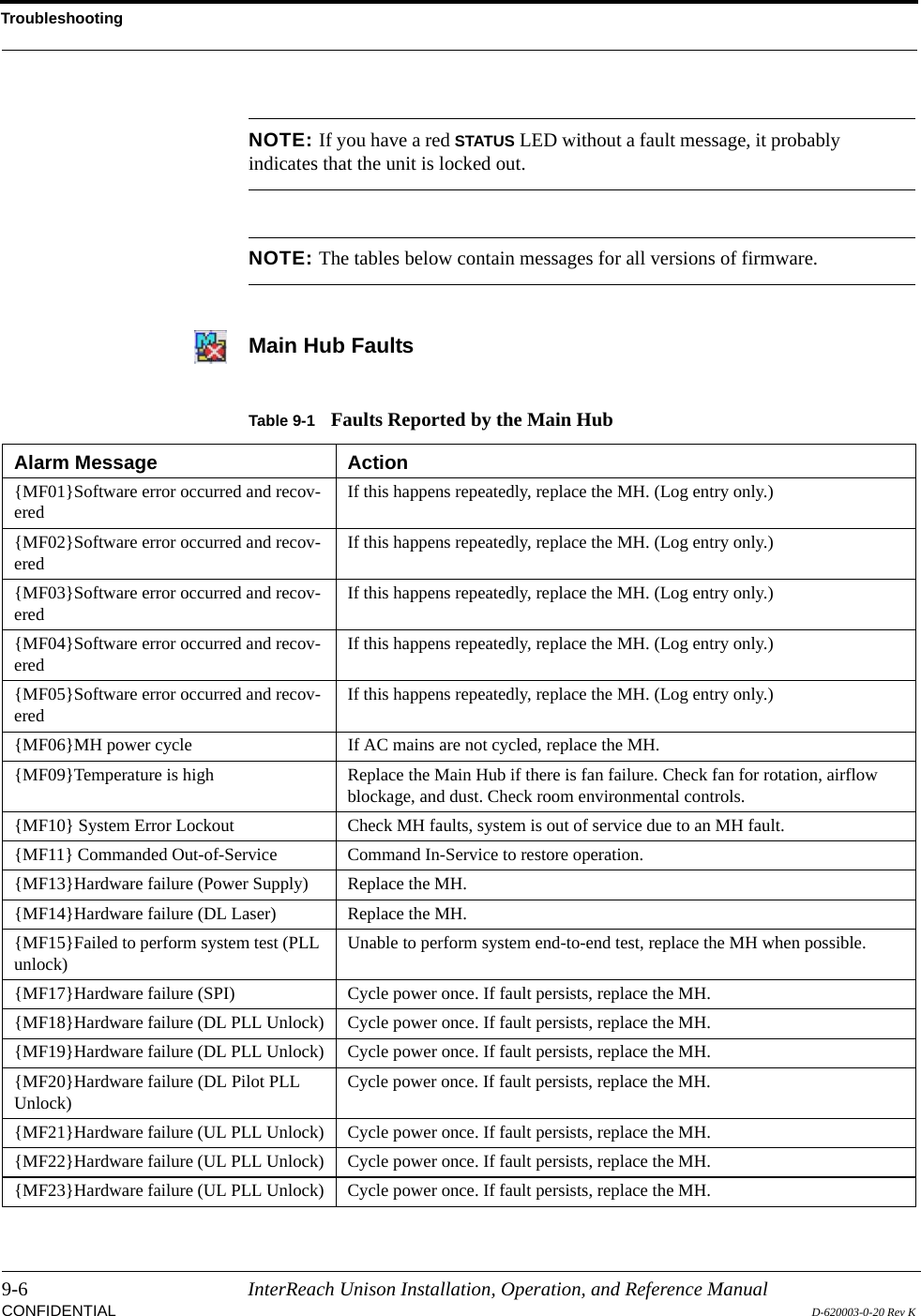
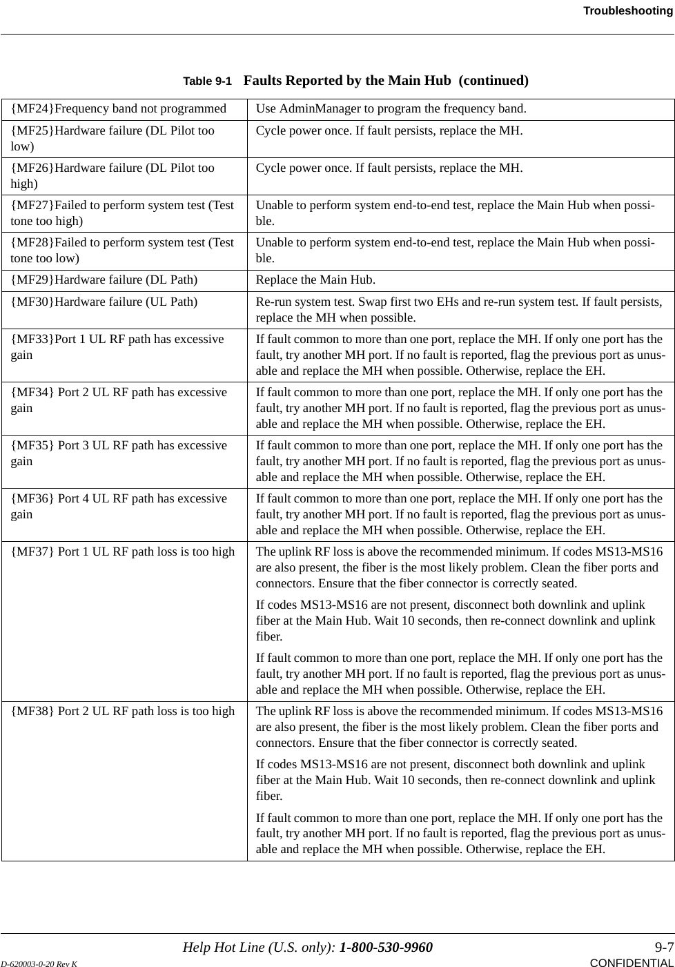
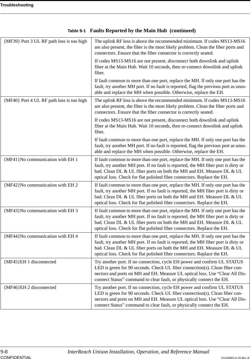
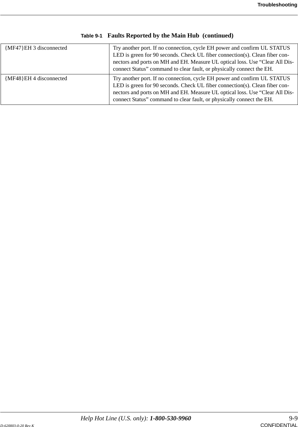
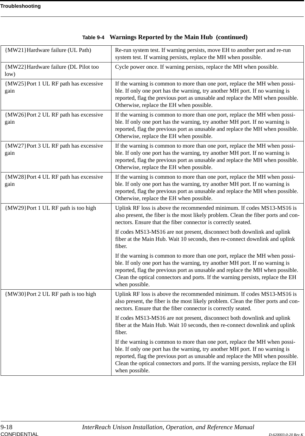
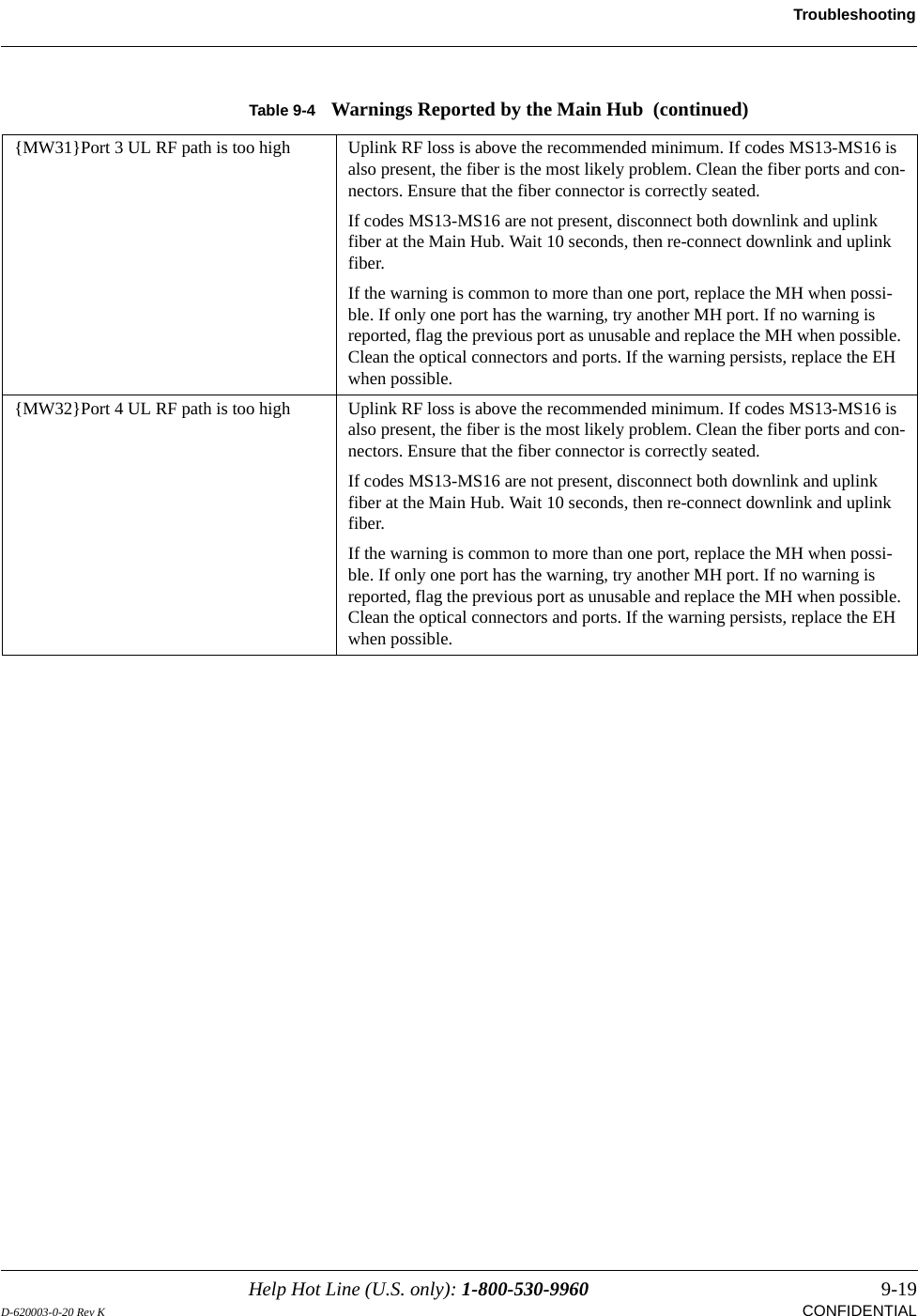
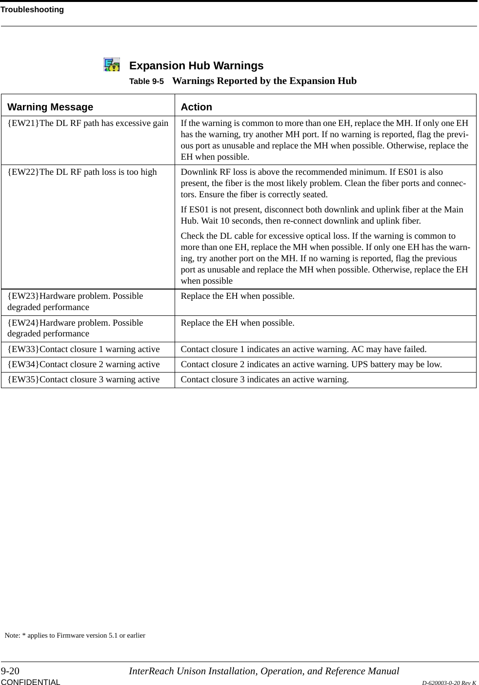
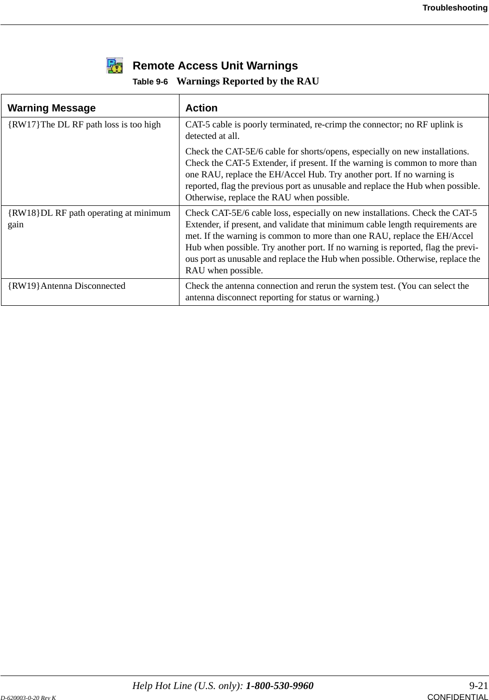
![2-2 InterReach Unison Installation, Operation, and Reference ManualCONFIDENTIAL D-620003-0-20 Rev KKey System Features•Superior RF performance, particularly in the areas of IP3 and noise figure.•High downlink composite power and low uplink noise figure for support of a large number of channels and larger coverage footprint per antenna.•Software configurable Main and Expansion Hubs. Thus, the frequency band can be configured in the field.•Either single-mode or multi-mode fiber can be used, supporting flexible cabling alternatives (in addition to standard Cat-5, Cat-5E, or Cat-6 screened twisted pair [ScTP]). You can select the cabling type to meet the resident cabling infrastructure of the facility and unique building topologies.•Extended system “reach.” Using single-mode fiber, fiber runs can be as long as 6 kilometers (creating a total system “wingspan” of 12 kilometers). Alternately, with multi-mode fiber, fiber runs can be as long as 1.5 kilometers. The Cat-5/5E/6 ScTP cable run can be up to 100 meters recommended maximum, or up to 170 meters when using a Cat-5 Extender.•Flexible RF configuration capabilities, including:• System gain:– Ability to manually set gain in 1 dB steps, from 0 to 15 dB, on both down-link and uplink.•RAU:– RAU uplink and downlink gain can be independently attenuated 10 dB.– Uplink level control protects the system from input overload and can be optimized for either a single operator or multiple operators/protocols.– VSWR check on RAU reports if there is a disconnected antenna (all RAUs except UMTS-1).•Firmware Updates are downloaded (either locally or remotely) to operating sys-tems when any modifications are made to the product, including the addition of new software capabilities/services.•Extensive OA&M capabilities, including fault isolation to the field replaceable unit, automatic reporting of all fault and warning conditions, and user-friendly graphical-user interface OA&M software packages.](https://usermanual.wiki/ADC-Telecommunications/UNS-PS70-1/User-Guide-889564-Page-22.png)
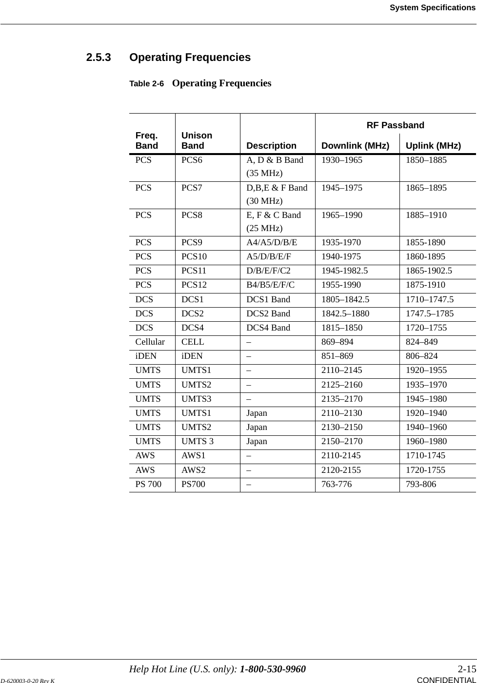
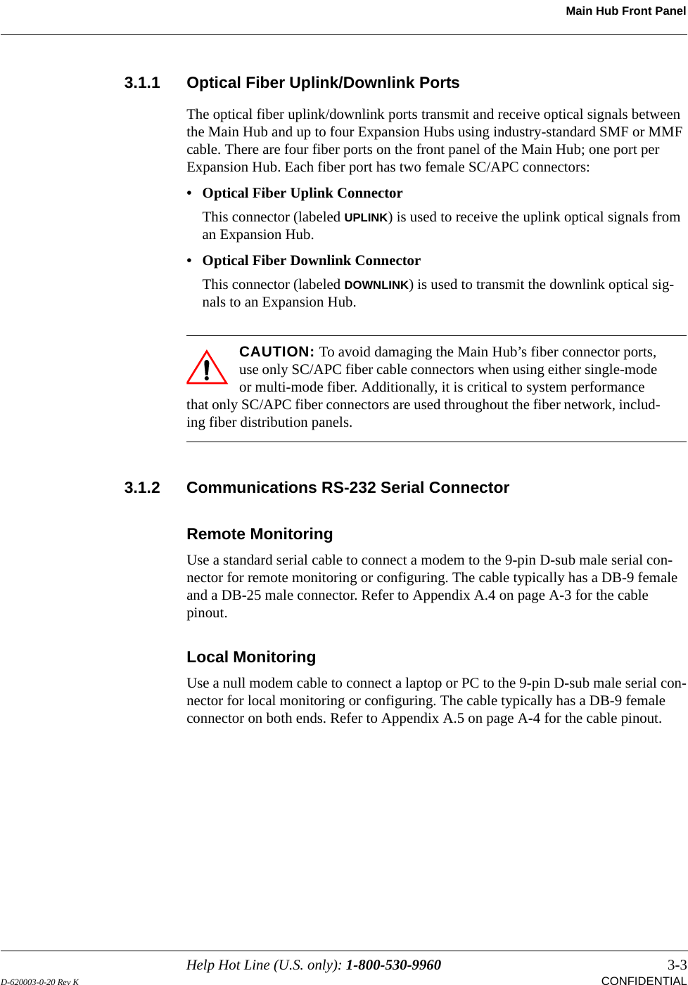
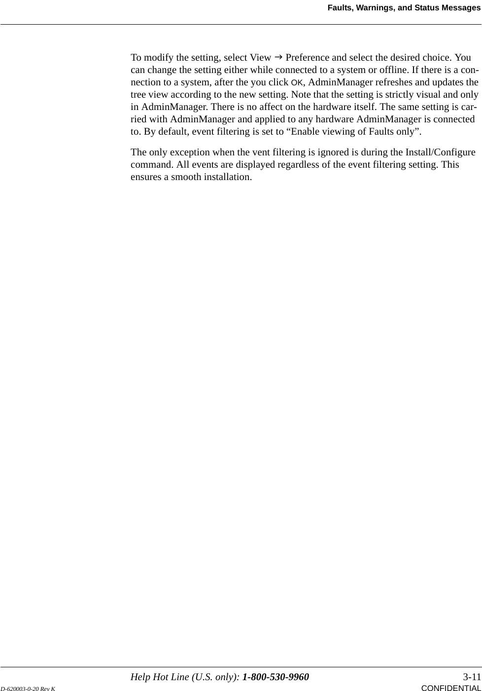

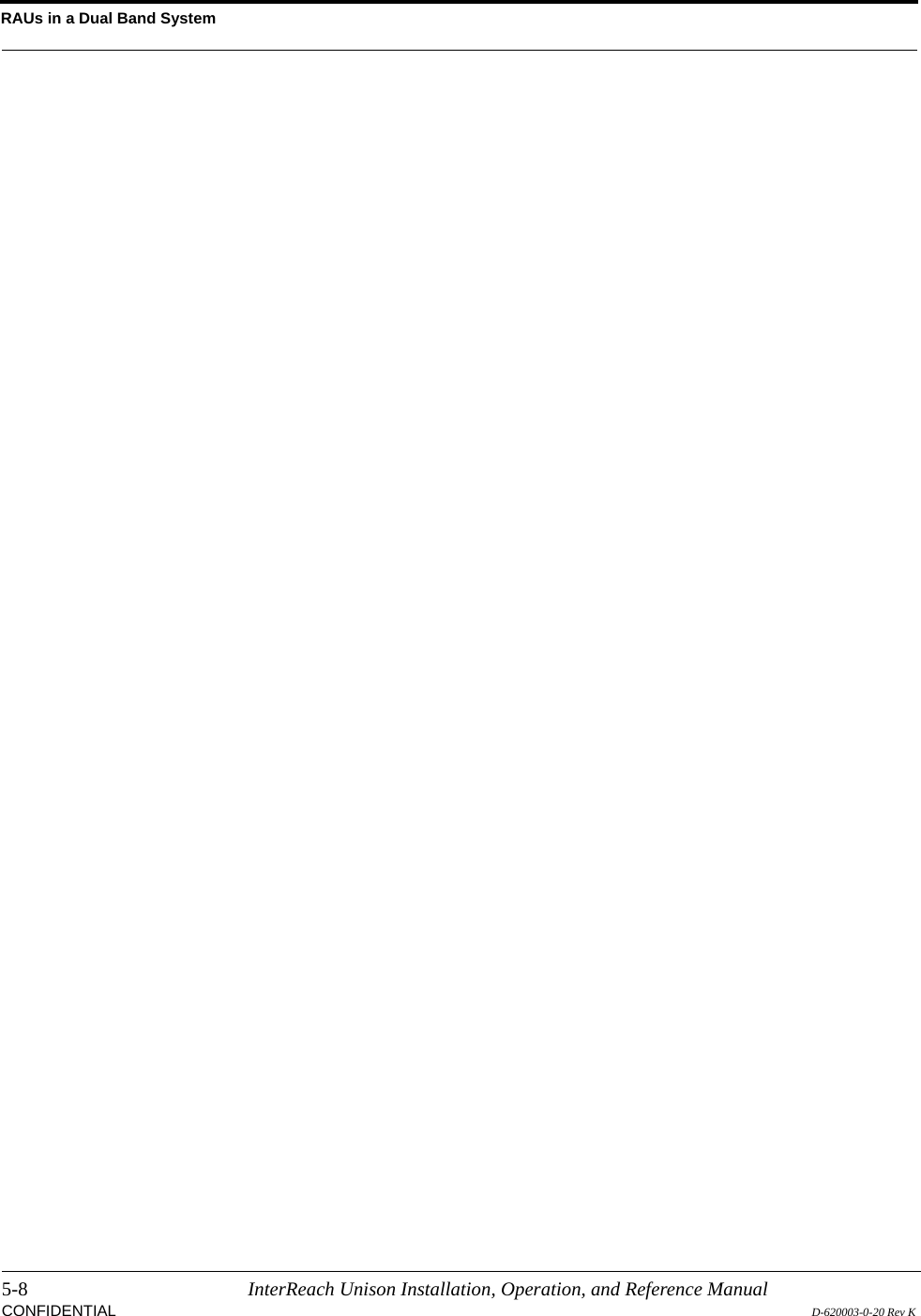
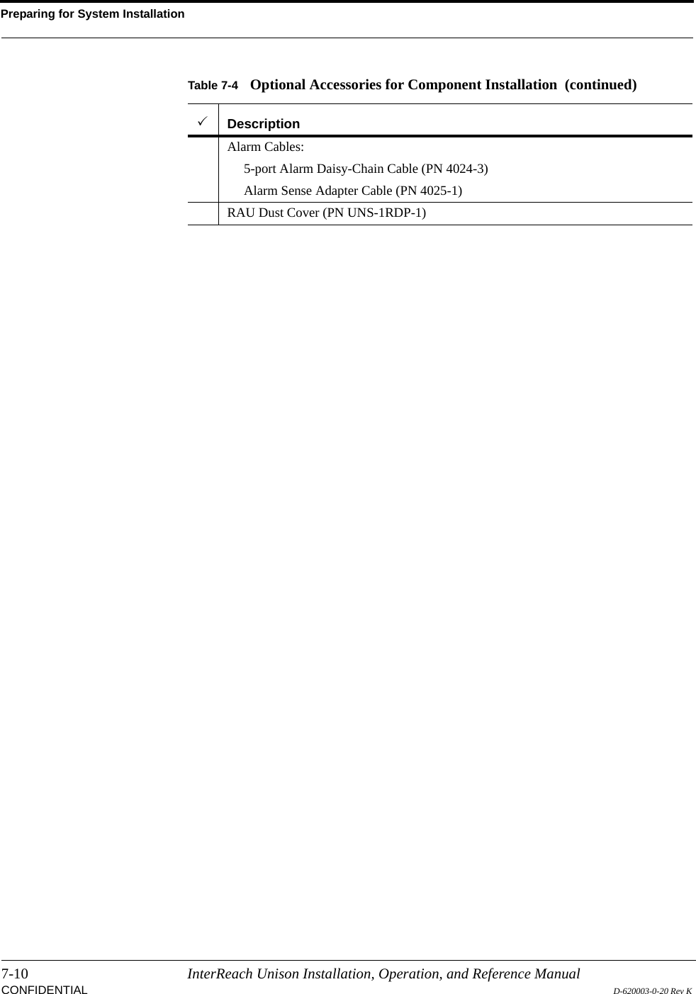
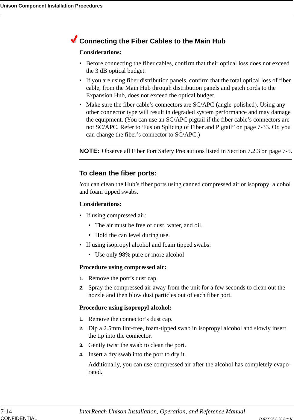

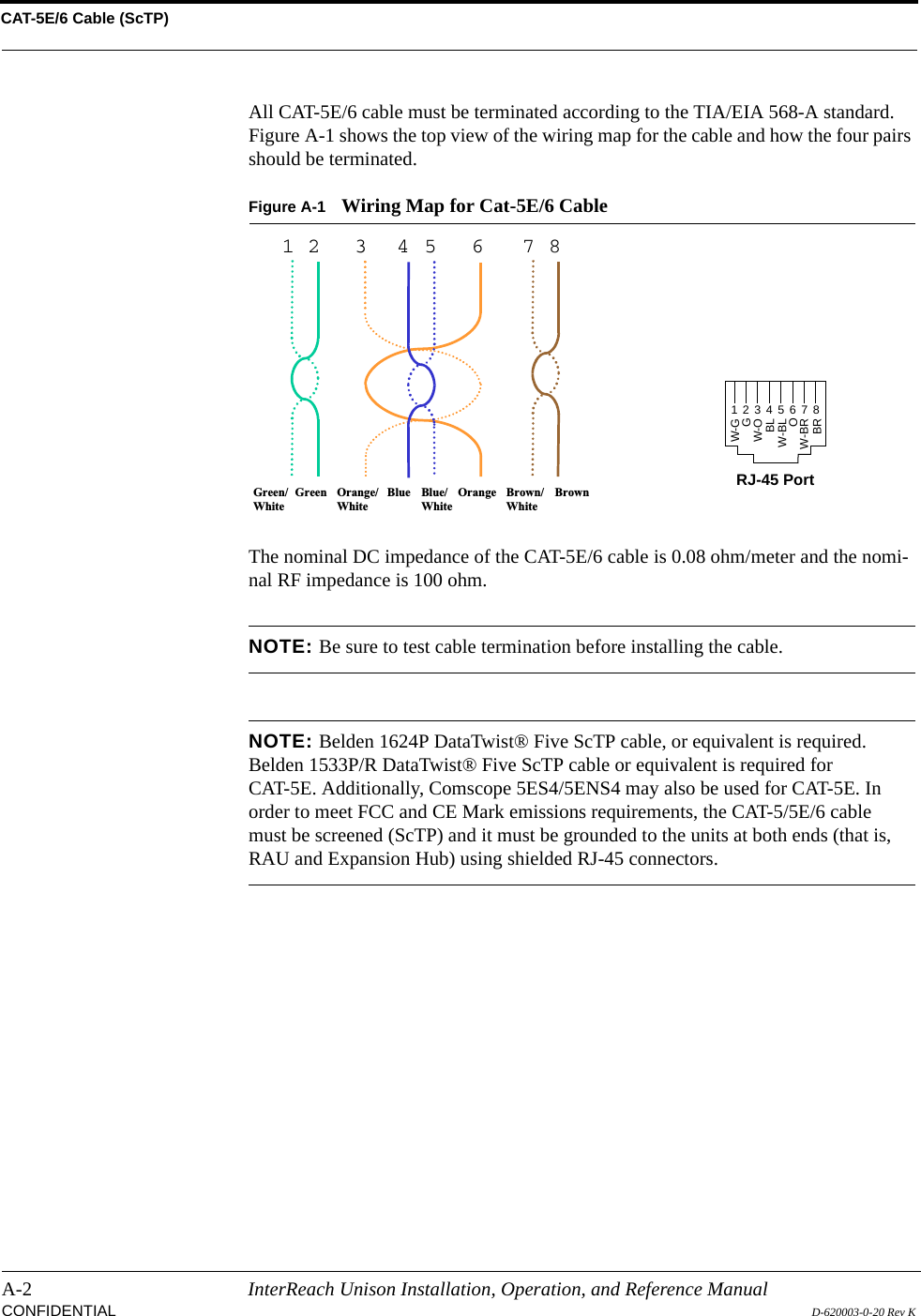
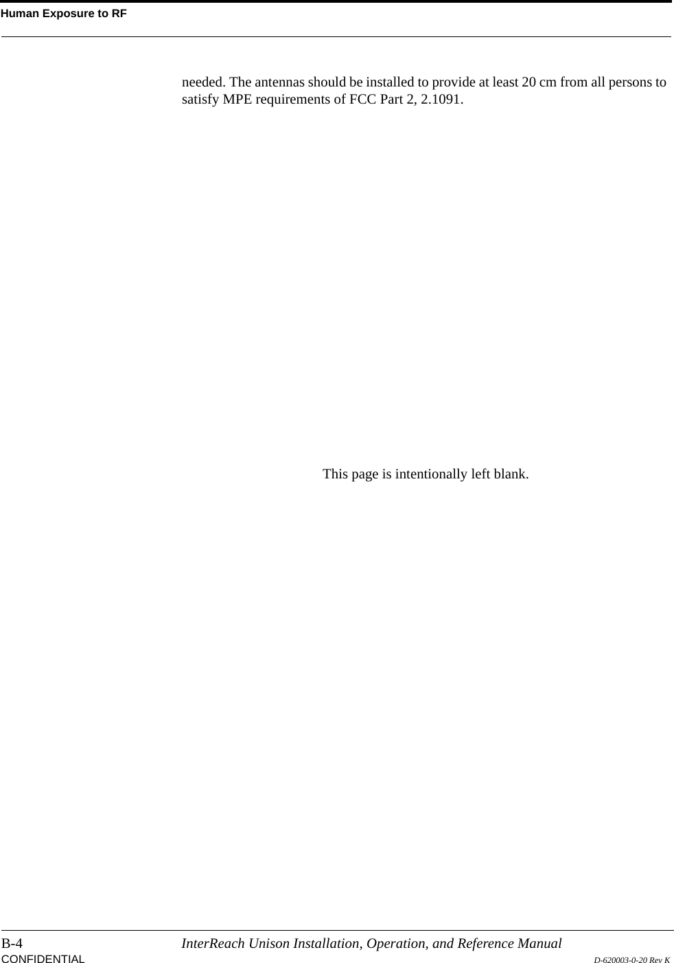
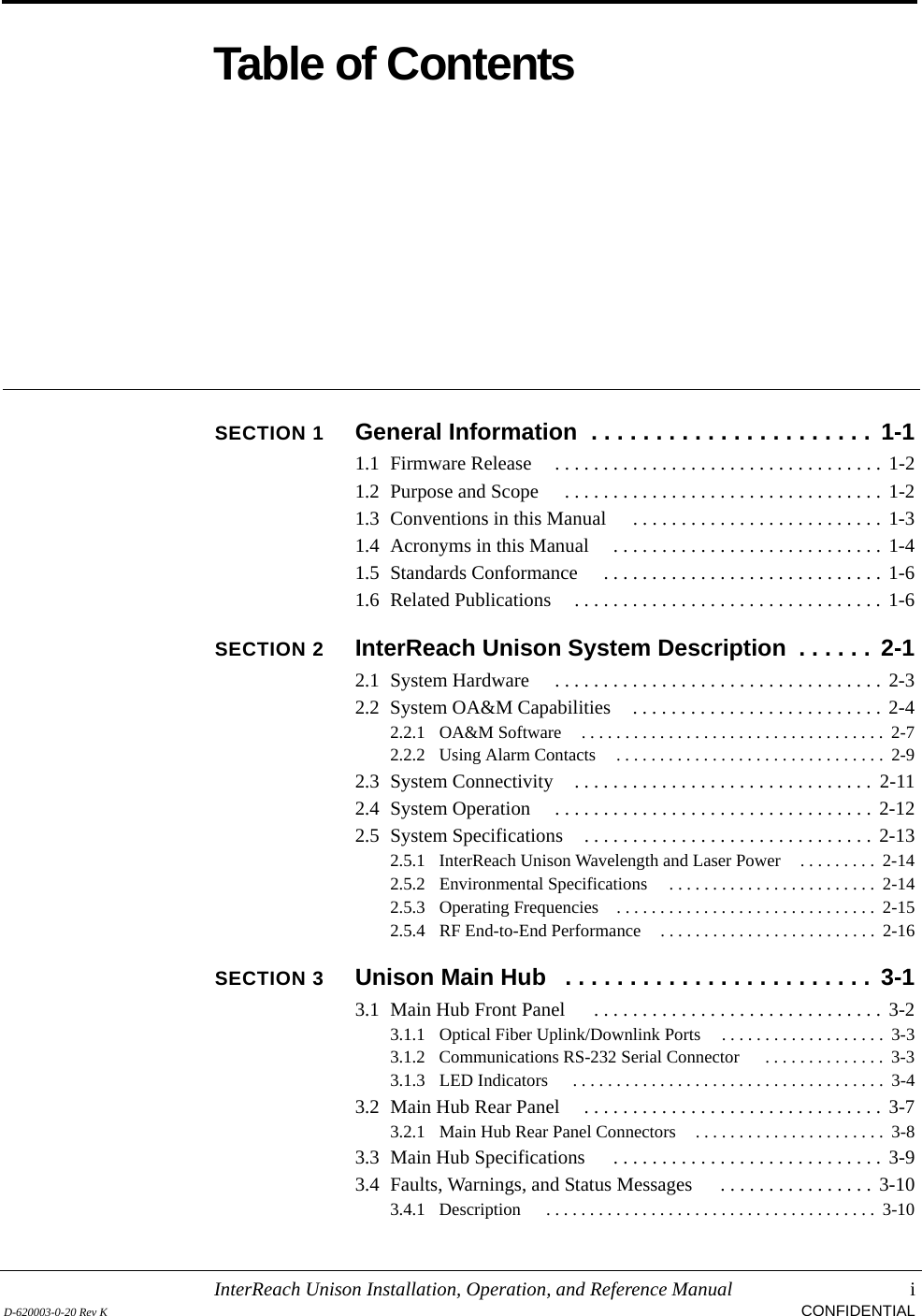
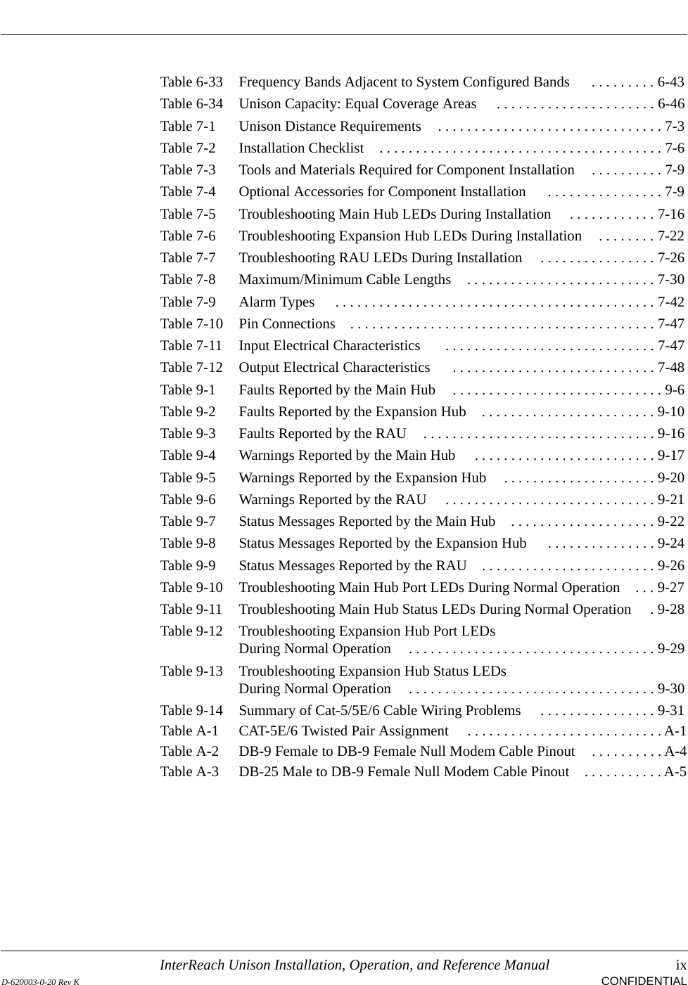
![Troubleshooting9-22 InterReach Unison Installation, Operation, and Reference ManualCONFIDENTIAL D-620003-0-20 Rev K9.3.1.4 Status MessagesStatus messages alert you to conditions that are important but do not generally impact service. Status messages are displayed in the Messages pane in blue lettering.NOTE: AdminManager v2.04 or higher displays events (faults, warnings, or status messages) depending on your view preference. To change your view preference, refer to Section 3.4.2, “View Preference,” on page 3-10.NOTE: The icons displayed in the system status tree assume that there are no other faults or warnings present.Main Hub Status MessagesTable 9-7 Status Messages Reported by the Main Hub Status Message Action[MS03]Downlink laser is failing Replace the MH when possible.[MS04]Fan failure Check the fan for rotation, airflow blockage, and dust. Replace the MH on high temperature warning.[MS05]Commanded Out-of-Service Command In-service to restore operation.[MS06]Factory special test mode Cycle the power to clear.[MS07]System Lockout Check the MH for faults.[MS08]Unable to perform system test on power up Check the EHs and RAUs for faults. Re-run system test.[MS09]EH1/RAU reports warning condi-tion Check EH 1 and the RAU for warnings.[MS10]EH2/RAU reports warning condi-tion Check EH 2 and the RAU for warnings.[MS11]EH3/RAU reports warning condi-tion Check EH 3 and the RAU for warnings.[MS12]EH4/RAU reports warning condi-tion Check EH 4 and the RAU for warnings.[MS13]Port 1 UL fiber interface has high optical loss Uplink optical loss is above the recommended minimum. If periodic messages MF45-MF48 (EH disconnects) occur, the fiber optical loss is near the absolute minimum.Excessive uplink optical loss may also result in MW29-MF32 codes.Clean the fiber cable connectors and ports.](https://usermanual.wiki/ADC-Telecommunications/UNS-PS70-1/User-Guide-889564-Page-200.png)
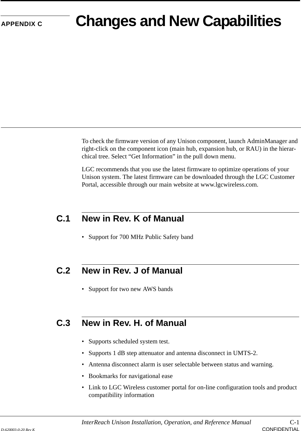
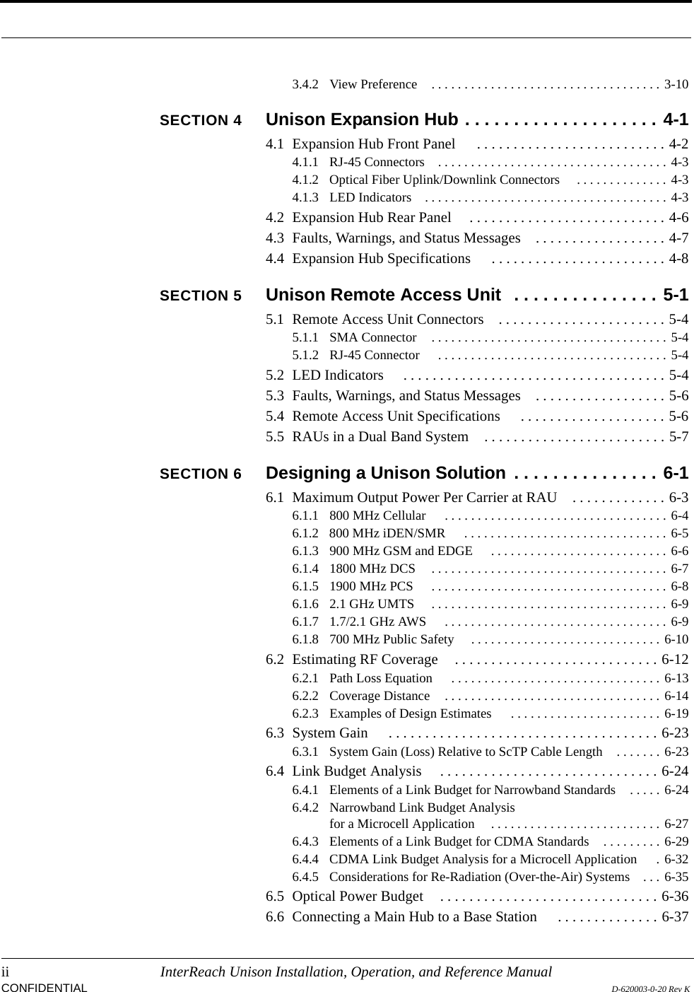
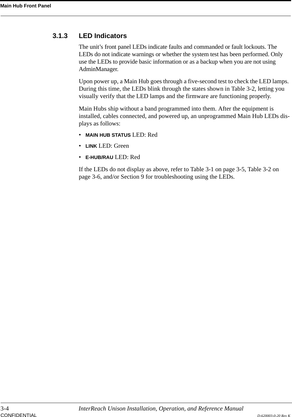
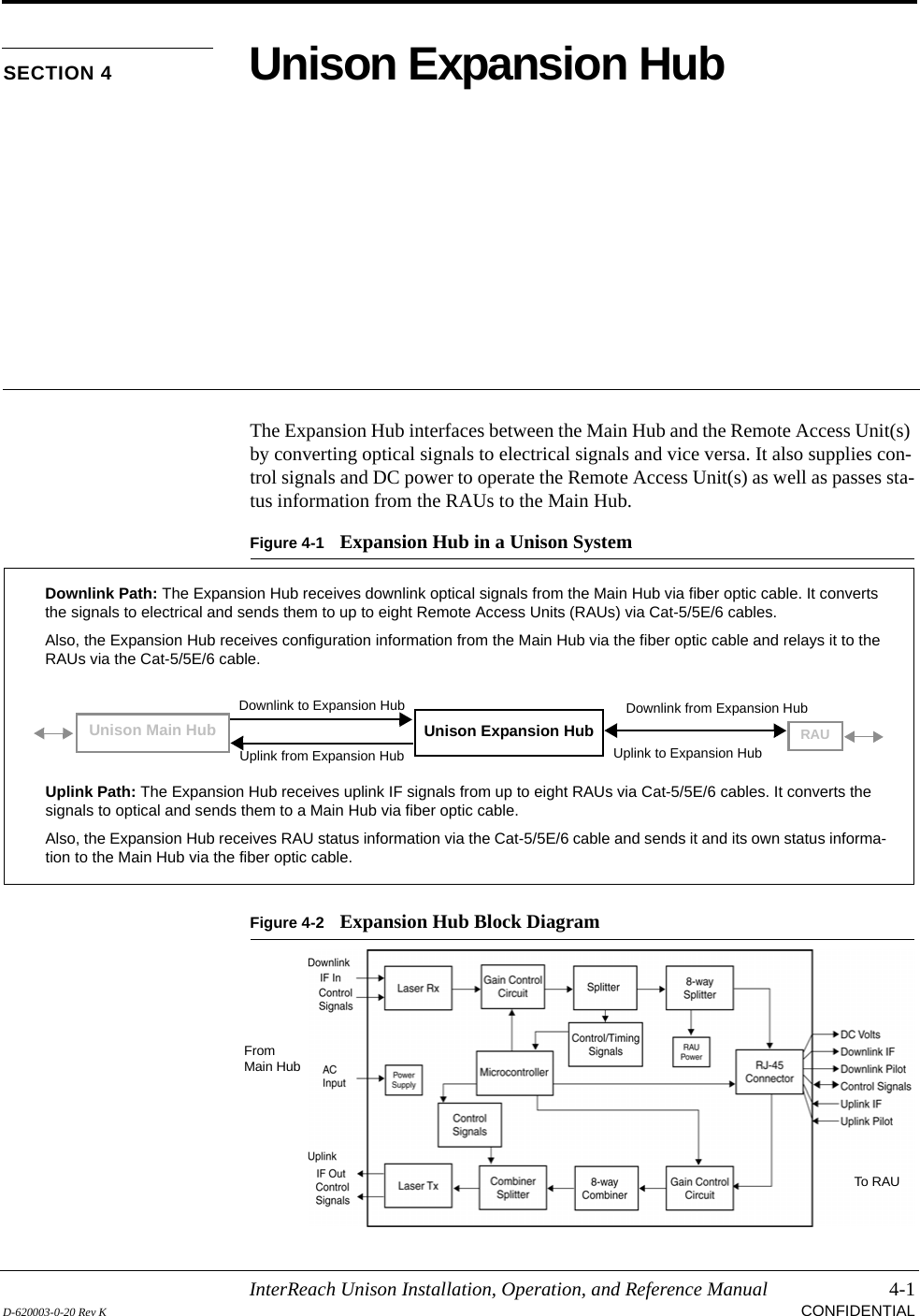
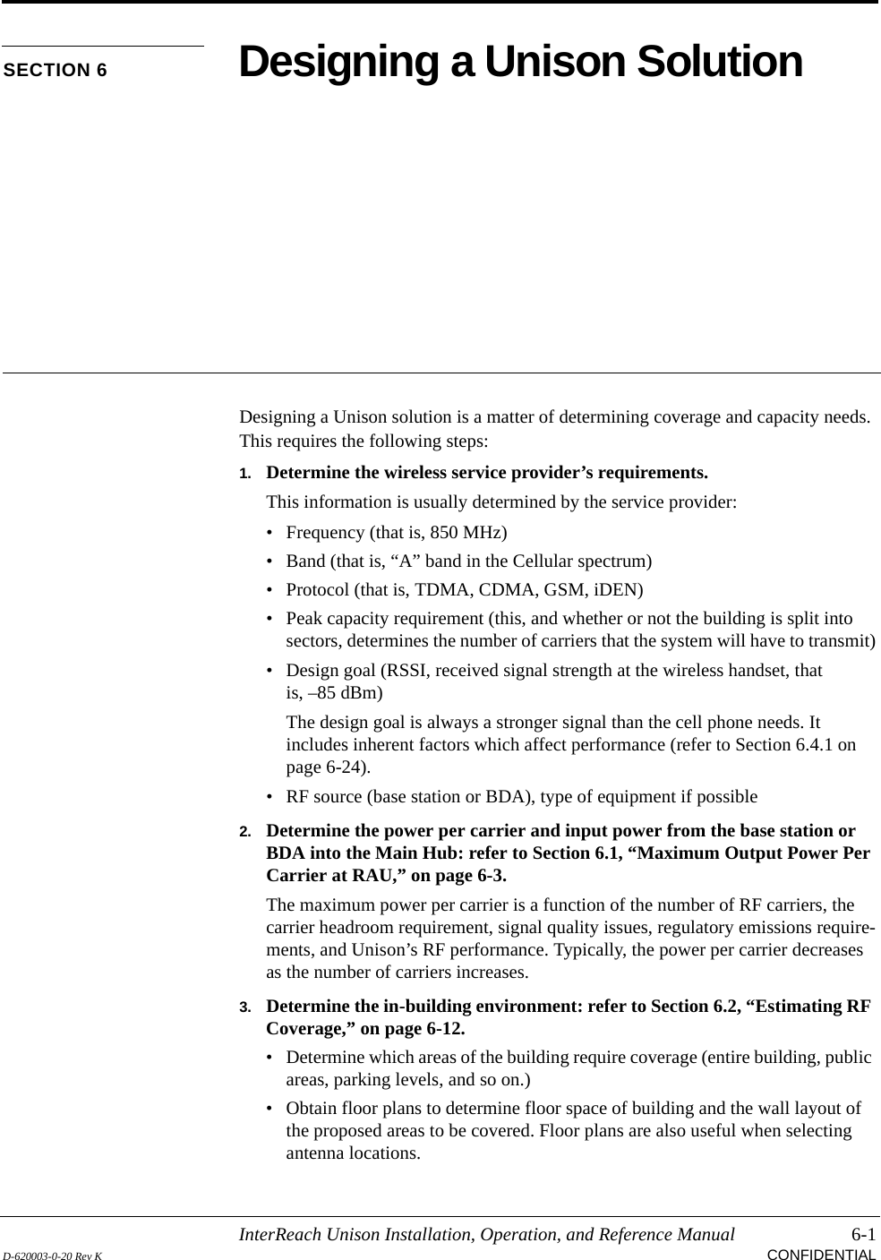
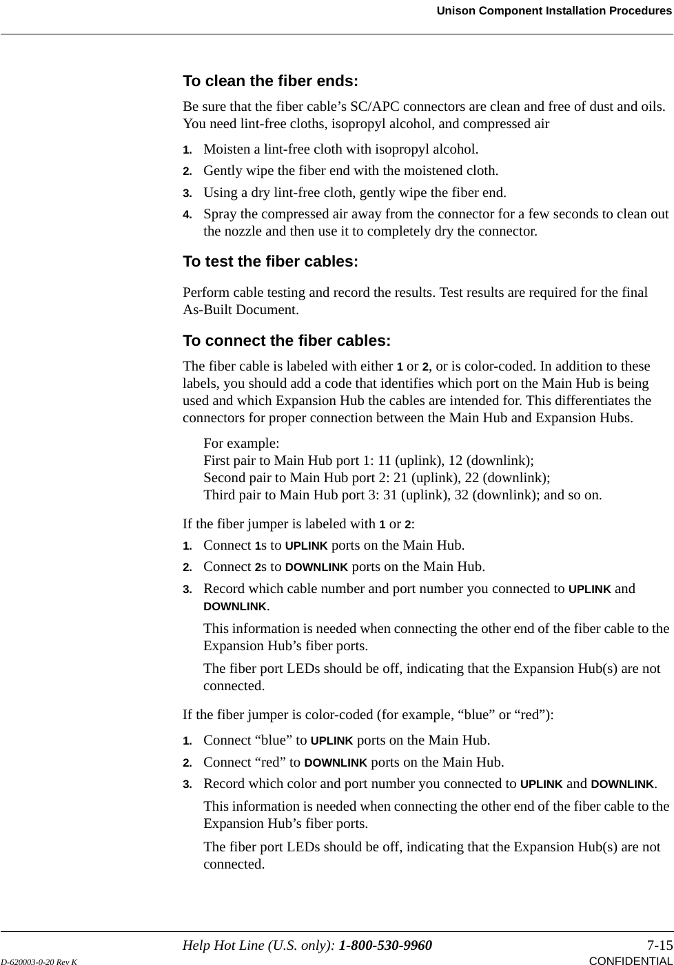
![Help Hot Line (U.S. only): 1-800-530-9960 9-23D-620003-0-20 Rev K CONFIDENTIALTroubleshootingNOTE: If your equipment is using release 3.1 firmware, the icon is displayed instead of , except for “unable to perform system test on power up”.[MS14]Port 2 UL fiber interface has high optical loss Uplink optical loss is above the recommended minimum. If periodic messages MF45-MF48 (EH disconnects) occur, the fiber optical loss is near the absolute minimum.Excessive uplink optical loss may also result in MW29-MF32 codes.Clean the fiber cable connectors and ports. [MS15]Port 3 UL fiber interface has high optical loss Uplink optical loss is above the recommended minimum. If periodic messages MF45-MF48 (EH disconnects) occur, the fiber optical loss is near the absolute minimum.Excessive uplink optical loss may also result in MW29-MF32 codes.Clean the fiber cable connectors and ports. [MS16]Port 4 UL fiber interface has high optical loss Uplink optical loss is above the recommended minimum. If periodic messages MF45-MF48 (EH disconnects) occur, the fiber optical loss is near the absolute minimum.Excessive uplink optical loss may also result in MW29-MF32 codes.Clean the fiber cable connectors and ports. [MS17]Failed to perform system test (PLL unlock) Unable to perform system end-to-end test, replace the MH when possible.[MS18]Failed to perform system test (Test tone too high) Unable to perform system end-to-end test, replace the MHb when possible.[MS19]Failed to perform system test (Test tone too low) Unable to perform system end-to-end test, replace the MH when possible.[MS23] Scheduled system test completed Scheduled system test completed, log entry only. [MS33] Time Tagged Log Full Use AdminManager to dump and save the Time-Tagged Log, then erase it.[MS34] Time of day not initialized Use AdminManager to initialize the time and date. [MS36] Maximum auto-recovery limit Maximum number of fault/warning auto-recovery attempts. Use AdminMan-ager to “Set In-Service” to allow the MH to attempt additional auto-recovery attempts.Table 9-7 Status Messages Reported by the Main Hub (continued)](https://usermanual.wiki/ADC-Telecommunications/UNS-PS70-1/User-Guide-889564-Page-201.png)
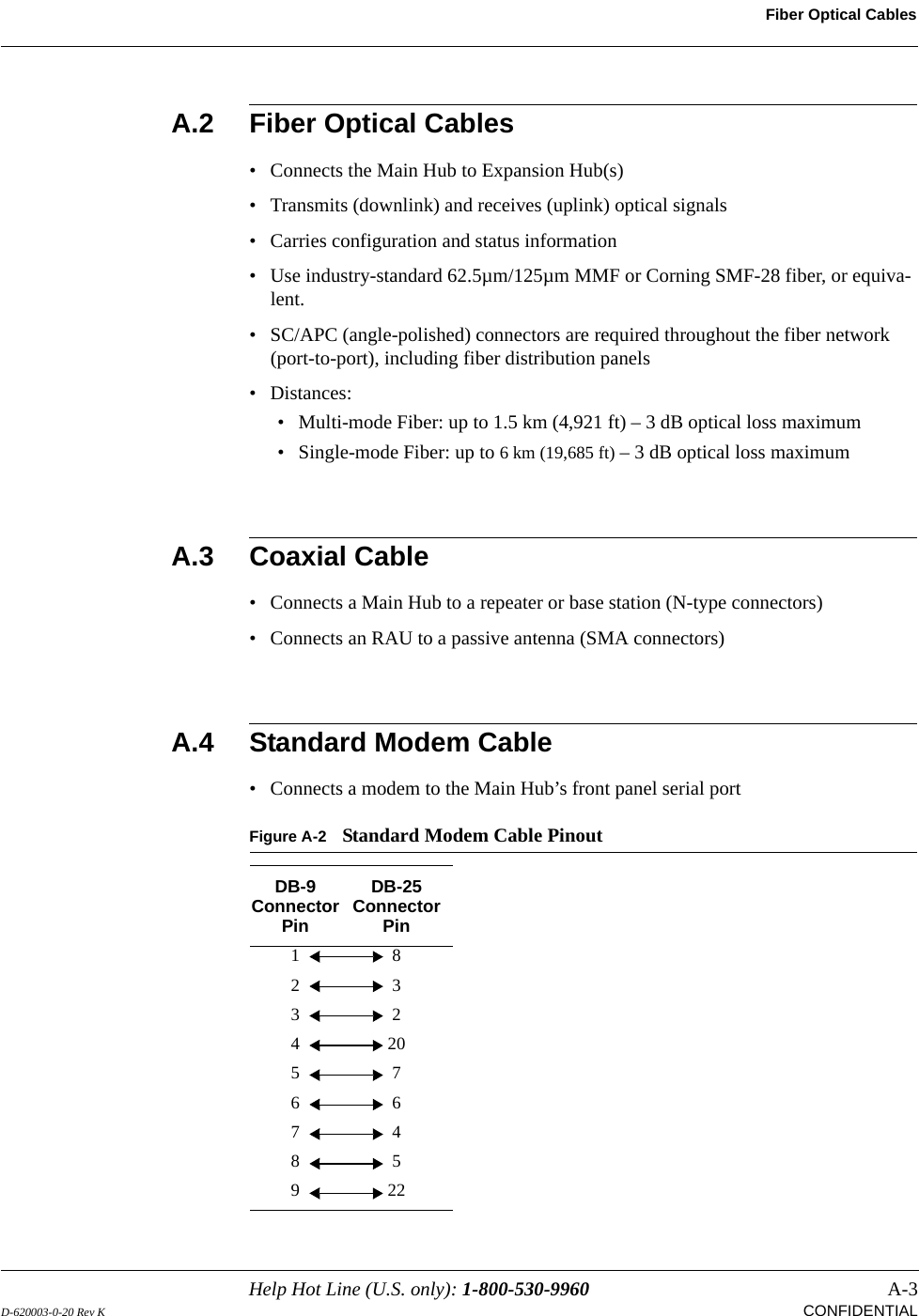
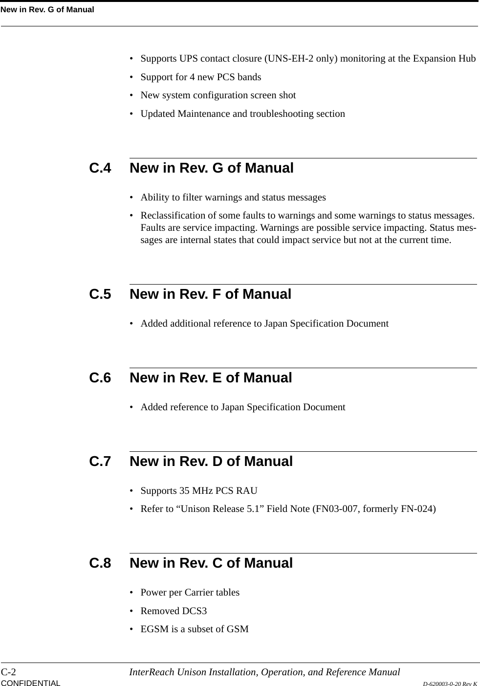
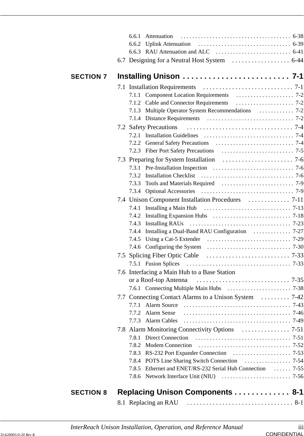
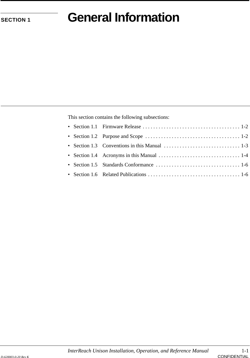
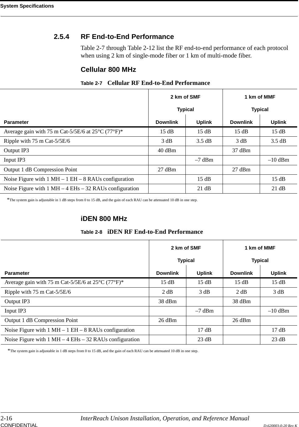
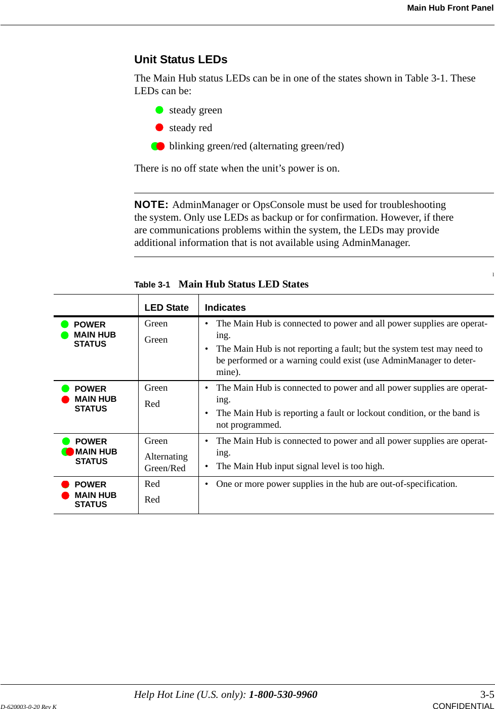
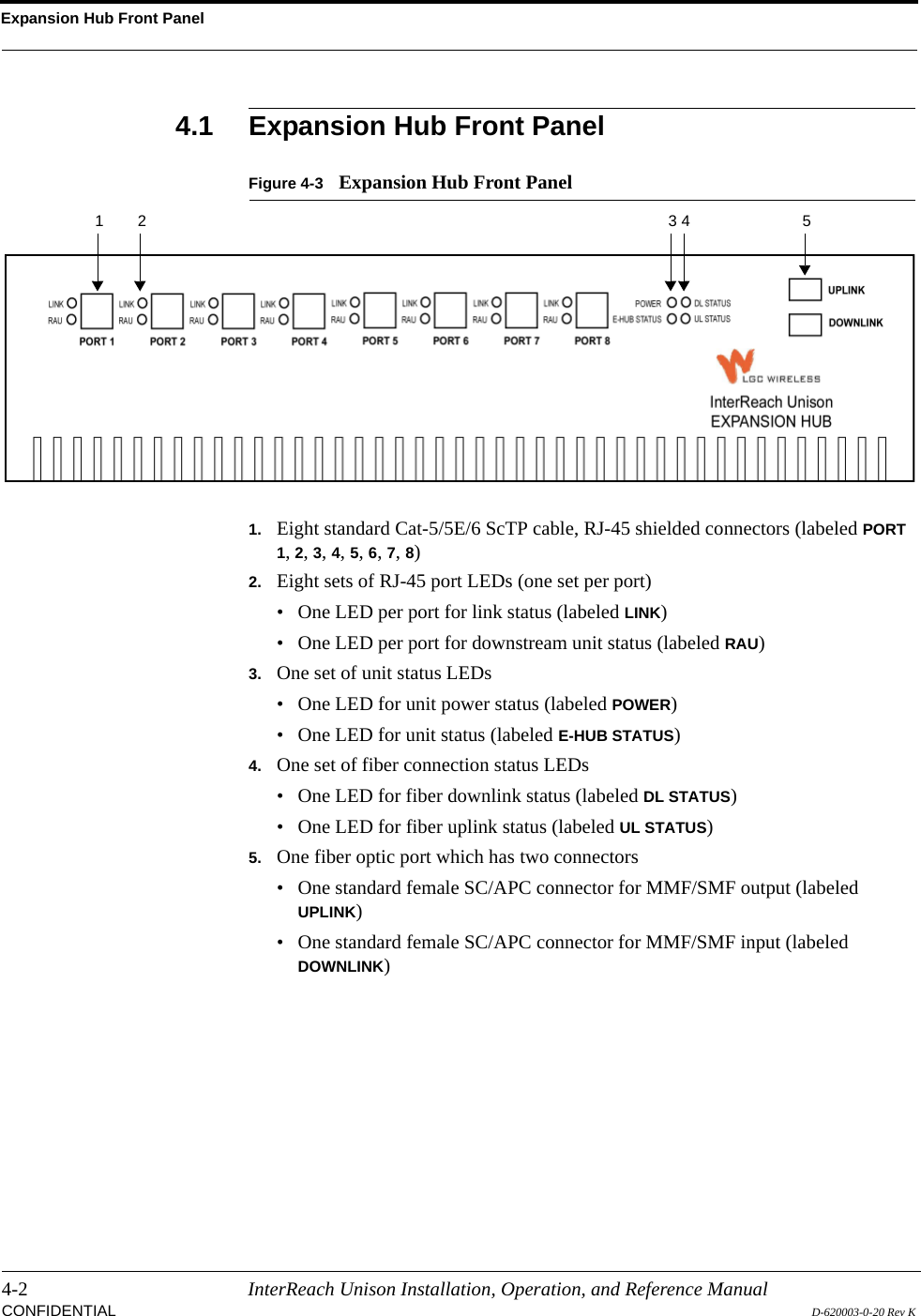
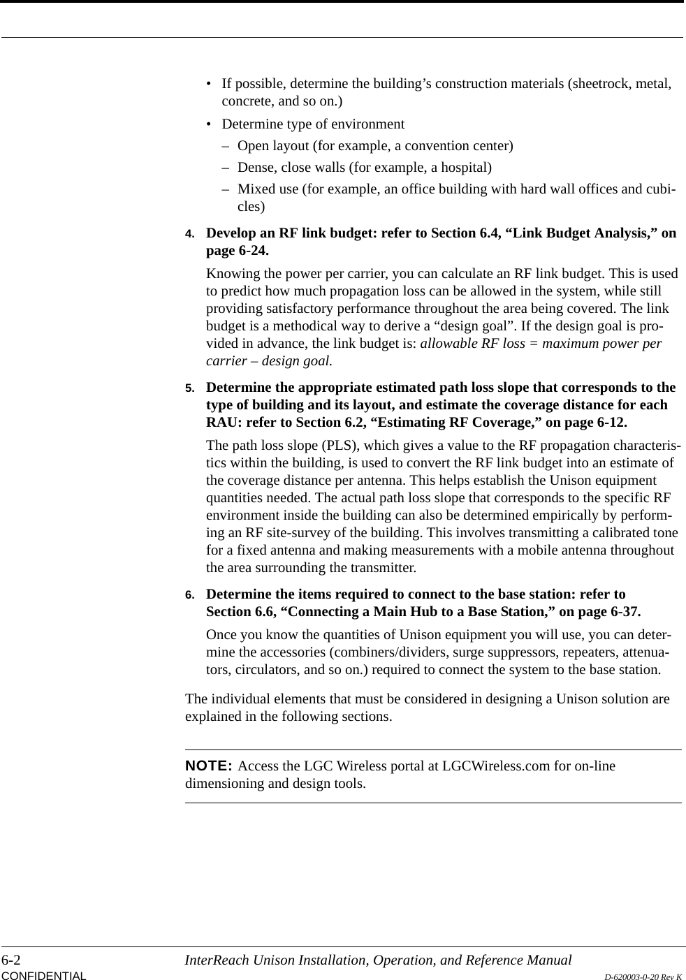
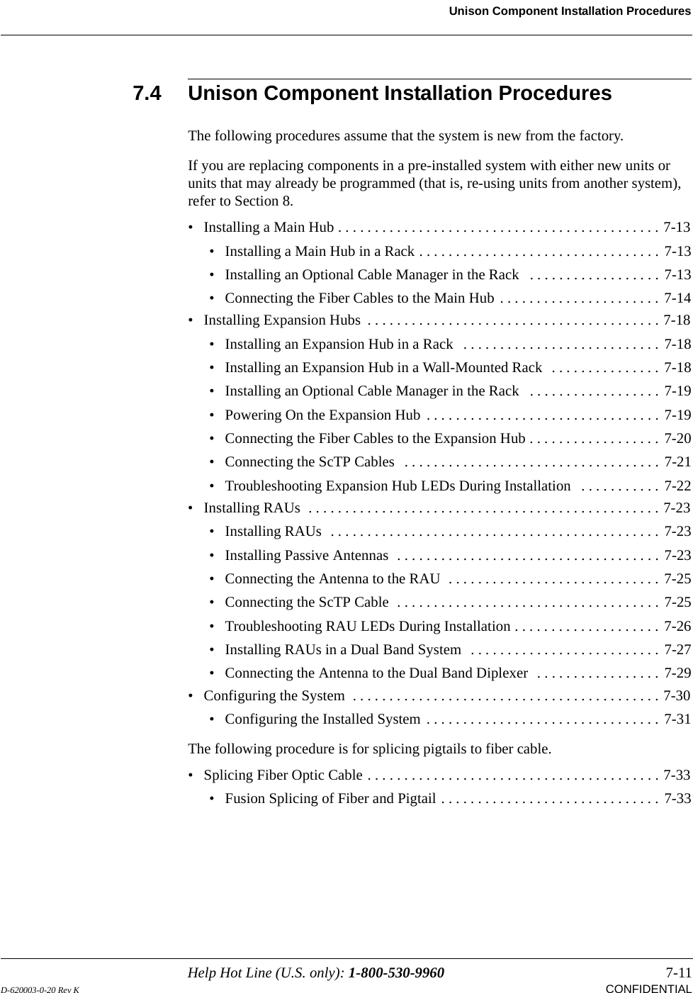
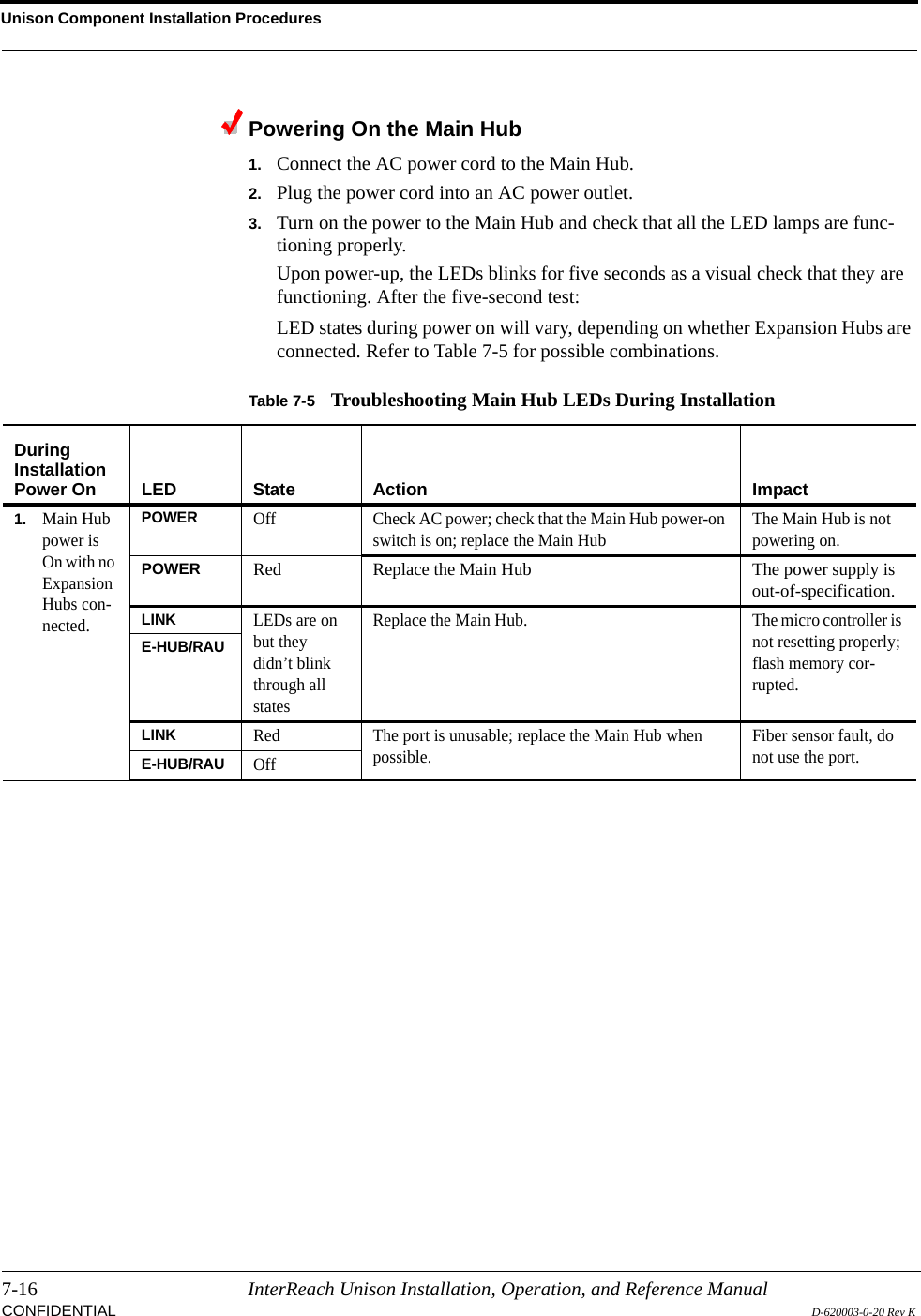
![Troubleshooting9-24 InterReach Unison Installation, Operation, and Reference ManualCONFIDENTIAL D-620003-0-20 Rev KExpansion Hub Status MessagesTable 9-8 Status Messages Reported by the Expansion Hub Status Message Action[ES01]The DL fiber interface has high opti-cal loss Downlink optical loss is above THE recommended minimum. If codes MF41-MF44 (EH no communications) are observed, the fiber optical loss is near the absolute minimum.Excessive downlink optical loss may also result with ES02/EW22 codesClean the fiber connectors and ports, and check the DL cable for excessive optical loss.[ES02]The DL RF path loss is above the recommended limit Downlink RF loss is above the recommended minimum. If ES01 is also present, the fiber is the most likely problem. Clean the fiber ports and connec-tors. Ensure the fiber is correctly seated.If ES01 is not present, disconnect both downlink and uplink fiber at the Main Hub. Wait 10 seconds, then re-connect downlink and uplink fiber.[ES03]UL laser is failing Replace the Expansion Hub when possible.[ES04]System test required* Run the system test.[ES05]Temperature is high Check the fan for rotation, air flow blockage, and dust. Check the room envi-ronmental controls.[ES06]Fan 1 failure Check the fan for rotation, air flow blockage, and dust. Replace the EH on tem-perature fault.[ES07]Fan 2 failure Check the fan for rotation, air flow blockage, and dust. Replace the EH on tem-perature fault.[ES08]Fan 3 failure Check the fan for rotation, air flow blockage, and dust. Replace the EH on tem-perature fault.[ES09]Port 1 UL RF path loss is above the recommended limit Uplink RF is below the recommended minimum; the CAT-5 cable may be longer than the recommended minimum.Check the CAT-5E/6 cable, especially on new installations. Check the CAT-5 Extender, if present. Use the CAT-5 Extender to improve coverage.[ES10]Port 2 UL RF path loss is above the recommended limit Uplink RF is below the recommended minimum; the CAT-5 cable may be longer than the recommended minimum.Check the CAT-5E/6 cable, especially on new installations. Check the CAT-5 Extender, if present. Use the CAT-5 Extender to improve coverage.[ES11]Port 3 UL RF path loss is above the recommended limit Uplink RF is below the recommended minimum; the CAT-5 cable may be longer than the recommended minimum.Check the CAT-5E/6 cable, especially on new installations. Check the CAT-5 Extender, if present. Use the CAT-5 Extender to improve coverage.[ES12]Port 4 UL RF path loss is above the recommended limit Uplink RF is below the recommended minimum; the CAT-5 cable may be longer than the recommended minimum.Check the CAT-5E/6 cable, especially on new installations. Check the CAT-5 Extender, if present. Use the CAT-5 Extender to improve coverage.](https://usermanual.wiki/ADC-Telecommunications/UNS-PS70-1/User-Guide-889564-Page-202.png)
![Help Hot Line (U.S. only): 1-800-530-9960 9-25D-620003-0-20 Rev K CONFIDENTIALTroubleshootingNOTE: If your equipment is using release 3.1 firmware, the icon is displayed instead of , except for “unit not system tested”.[ES13]Port 5 UL RF path loss is above the recommended limit Uplink RF is below the recommended minimum; the CAT-5 cable may be longer than the recommended minimum.Check the CAT-5E/6 cable, especially on new installations. Check the CAT-5 Extender, if present. Use the CAT-5 Extender to improve coverage.[ES14]Port 6 UL RF path loss is above the recommended limit Uplink RF is below the recommended minimum; the CAT-5 cable may be longer than the recommended minimum.Check the CAT-5E/6 cable, especially on new installations. Check the CAT-5 Extender, if present. Use the CAT-5 Extender to improve coverage.[ES15]Port 7 UL RF path loss is above the recommended limit Uplink RF is below the recommended minimum; the CAT-5 cable may be longer than the recommended minimum.Check the CAT-5E/6 cable, especially on new installations. Check the CAT-5 Extender, if present. Use the CAT-5 Extender to improve coverage.[ES16]Port 8 UL RF path loss is above the recommended limit Uplink RF is below the recommended minimum; the CAT-5 cable may be longer than the recommended minimum.Check the CAT-5E/6 cable, especially on new installations. Check the CAT-5 Extender, if present. Use the CAT-5 Extender to improve coverage.[ES17]Commanded Out-of-Service Command In-service to restore operation.[ES18]External fault lockout Check the MH for faults.[ES20]Factory special test mode Cycle the power to clear the test mode.[ES25]Port 1 DL RF path too low Try another port. If the status persists, replace the EH. Otherwise, flag the pre-vious port as unusable and replace the EH when possible.[ES26]Port 2 DL RF path too low Try another port. If the status persists, replace the EH. Otherwise, flag the pre-vious port as unusable and replace the EH when possible.[ES27]Port 3 DL RF path too low Try another port. If the status persists, replace the EH. Otherwise, flag the pre-vious port as unusable and replace the EH when possible.[ES28]Port 4 DL RF path too low Try another port. If the status persists, replace the EH. Otherwise, flag the pre-vious port as unusable and replace the EH when possible.[ES29]Port 5 DL RF path too low Try another port. If the status persists, replace the EH. Otherwise, flag the pre-vious port as unusable and replace the EH when possible.[ES30]Port 6 DL RF path too low Try another port. If the status persists, replace the EH. Otherwise, flag the pre-vious port as unusable and replace the EH when possible.[ES31]Port 7 DL RF path too low Try another port. If the status persists, replace the EH. Otherwise, flag the pre-vious port as unusable and replace the EH when possible.[ES32]Port 8 DL RF path too low Try another port. If the status persists, replace the EH. Otherwise, flag the pre-vious port as unusable and replace the EH when possible.Table 9-8 Status Messages Reported by the Expansion Hub (continued)](https://usermanual.wiki/ADC-Telecommunications/UNS-PS70-1/User-Guide-889564-Page-203.png)
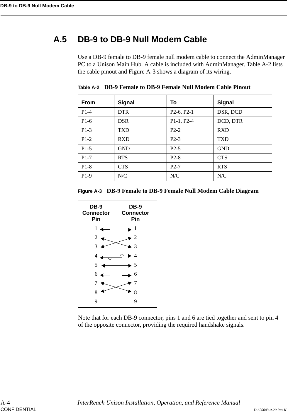
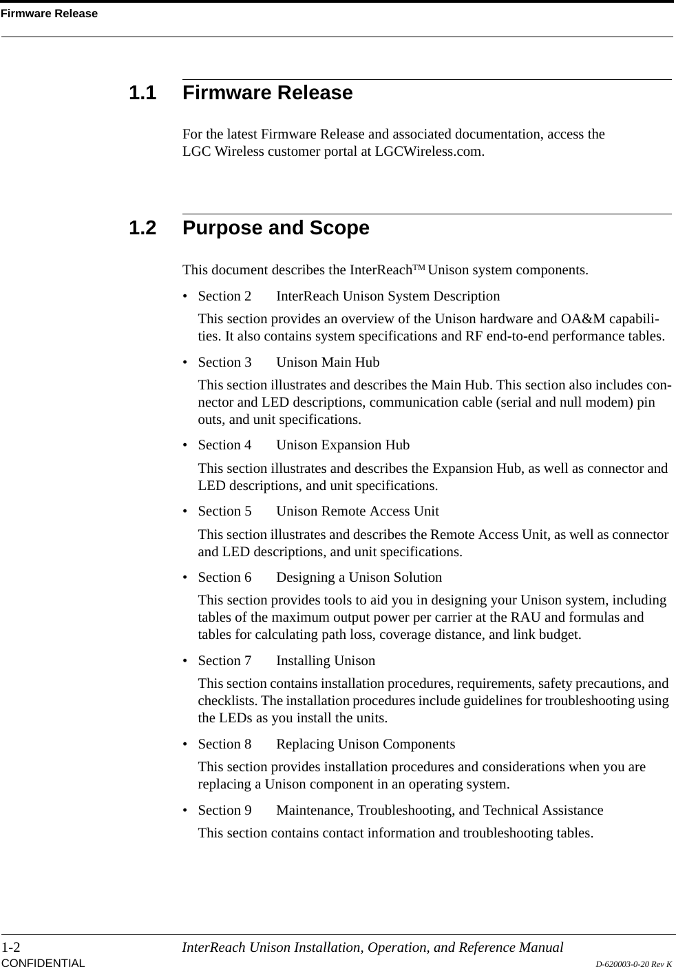
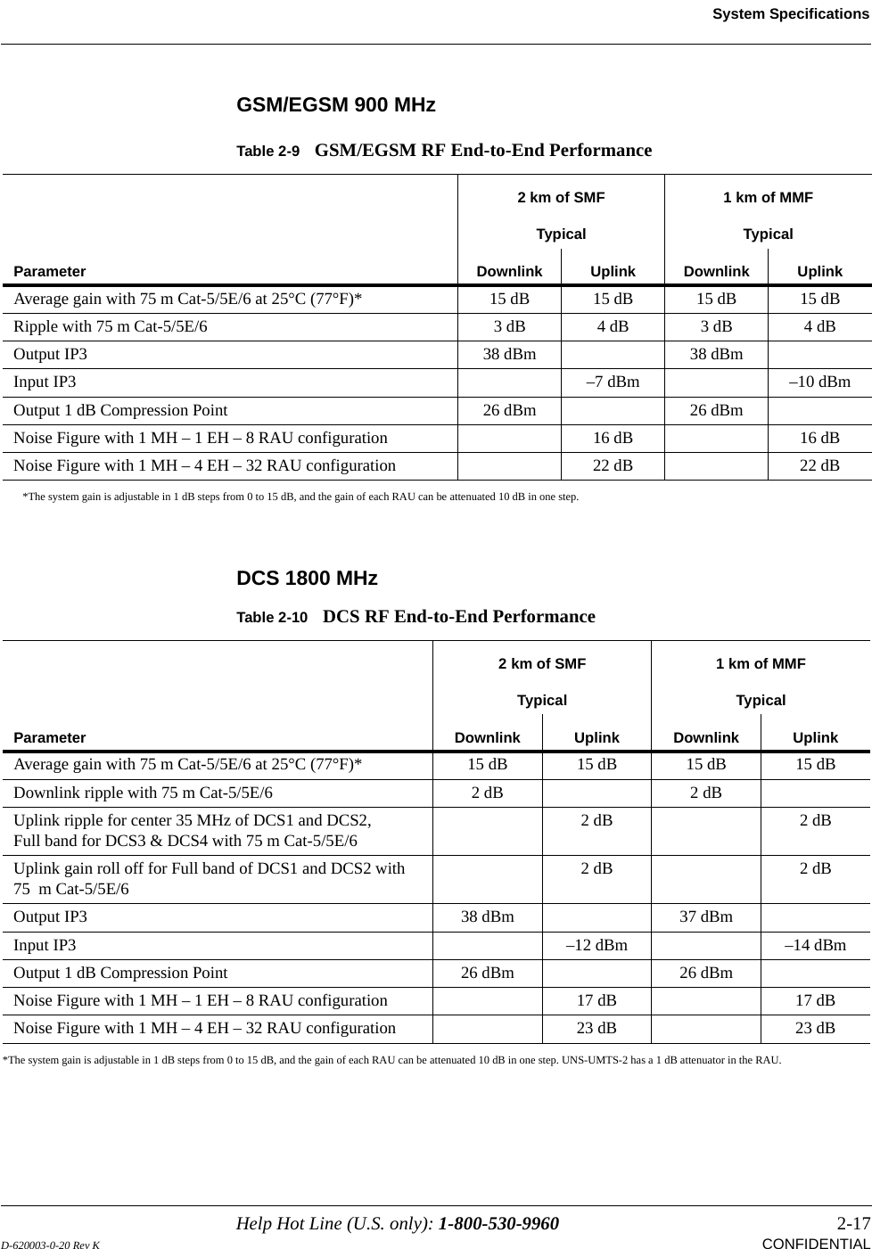
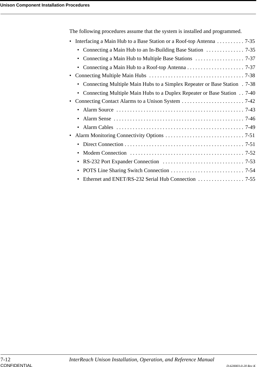
![Troubleshooting9-26 InterReach Unison Installation, Operation, and Reference ManualCONFIDENTIAL D-620003-0-20 Rev KRemote Access Unit Status MessagesNOTE: If your equipment is using release 3.1 firmware, the icon is displayed instead of , except for “unit not system tested”.Table 9-9 Status Messages Reported by the RAU Status Message Action[RS01]Temperature is high Check for proper installation. Check the environmental controls, move the RAU to a cooler environment.[RS02]DC voltage is low Check the CAT-5E/6 cable for shorts/opens, especially on new installations. Check the CAT-5 Extender, if present. If the status message persists, replace the RAU when possible.[RS03]Power amplifier is failing Replace the RAU when possible.[RS05] The cable loss between EH/Accel Hub and RAU is above the recommended limitThe downlink RF is below the recommended minimum; the CAT-5 cable may be longer than recommended.Check the CAT-5E/6 cable for shorts/opens, especially on new installations. Check the CAT-5 Extender, if present. If the status is common to more than one RAU, replace the EH/Accel Hub when possible. Use the CAT-5 Extender to improve coverage.[RS06]System test required Run the system test.[RS07]Antenna disconnected Check antenna connection and re-run system test. Note: With Firmware Release 5.5 and later, this alarm can be configured a either a status or a warning message (RW19).[RS09]Commanded Out-of-Service Command In-service to restore operation. Note: Message displays in Firmware Release 5.5 or earlier.[RS10]External fault lockout Check the Hubs for faults. Note: Message displays in Firmware Release 5.5 or earlier.[RS11]Internal fault lockout Check the RAU faults. The RAU is out-of-service. Note: Message displays in Firmware Release 5.5 or earlier.[RS13]DC Power supplied by the Expan-sion/Accel Hub is too high Check the CAT-5E/6 cable for shorts/opens, especially on new installations. Check the CAT-5 Extender, if present. If the status is common to more than one RAU, replace the EH/Accel Hub when possible. Try another port. If no status is reported, flag the previous port as unusable and replace the Hub when possible. Otherwise, replace the RAU when possible.[RS14]Potential failure in the UL RF path Unable to complete system end-to-end test. Replace the RAU when possible[RS15]Potential failure in the DL RF path Unable to complete system end-to-end test. Check the RAU termination at the SMA connector and re-test. Replace the RAU if there are no Hub alarms.[RS16]Factory special test mode Cycle the power to clear the test mode.](https://usermanual.wiki/ADC-Telecommunications/UNS-PS70-1/User-Guide-889564-Page-204.png)