ADC ACE COM L1 ThinMux Chassis User Manual To The 871fc9a0 4414 4e9f 8126 Eee2e1cdb7e2
User Manual: ADC ACE-COM L1 to the manual
Open the PDF directly: View PDF ![]() .
.
Page Count: 34
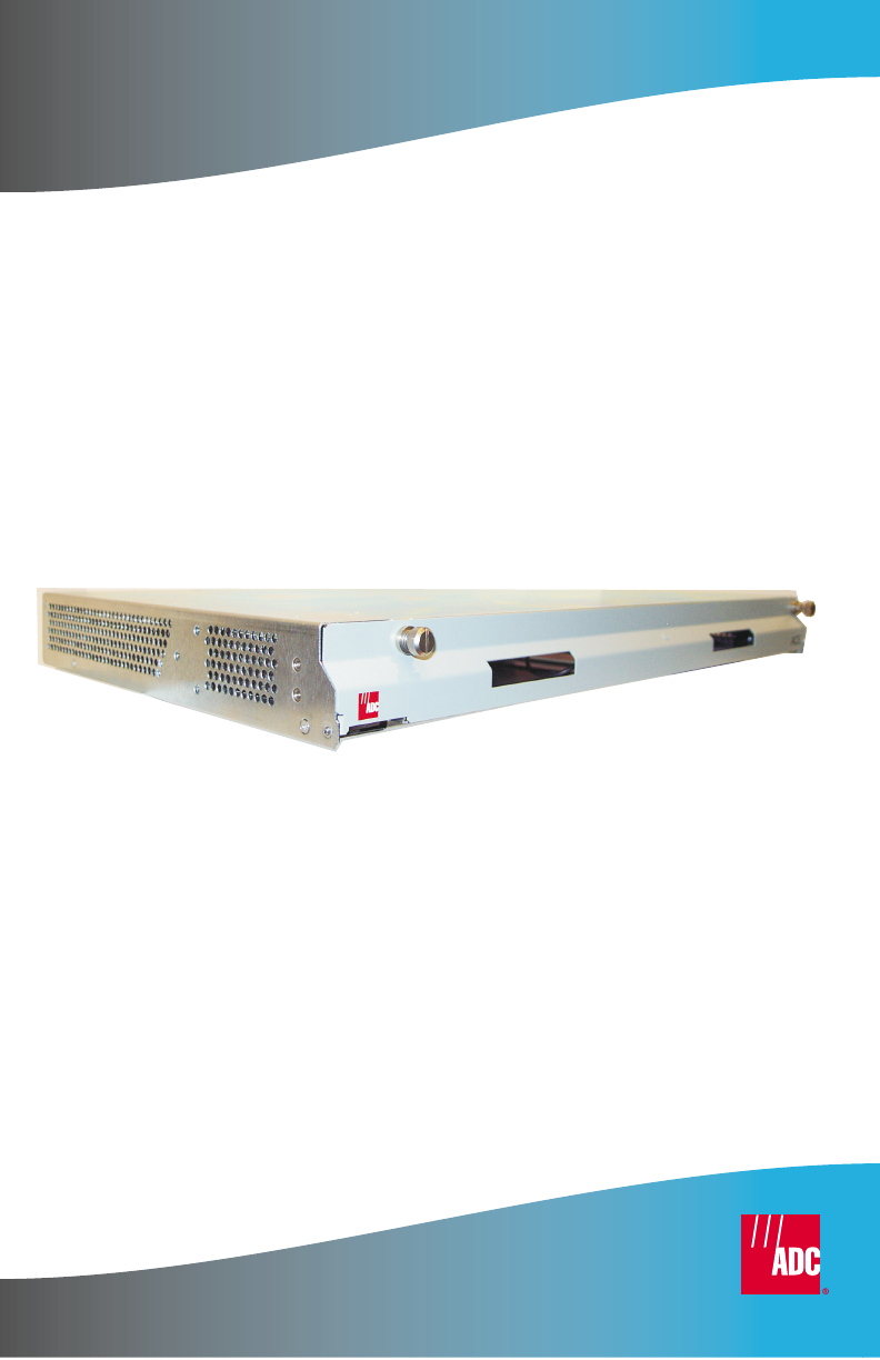
USER MANUAL
ThinMux Chassis
Product Catalog: ACE-COM L1
Part Number: 150-2263-01
CLEI: VAMXHN0F

LTPH-UM-1088-02, Issue 2
ii January 3, 2002 ThinMux Chassis
Revision History of Manual
To order copies of this document, use document catalog number
LTPH-UM-1088-02.
Copyright
January 3, 2002
© 2002 ADC DSL Systems, Inc. All rights reserved.
Trademark Information
ADC is a registered trademark of ADC Telecommunications, Inc. No right, license, or
interest to such trademarks is granted hereunder, and you agree that no such right,
license, or interest shall be asserted by you with respect to such trademark.
Other product names mentioned in this practice are used for identification purposes
only and may be trademarks or registered trademarks of their respective companies.
Disclaimer of Liability
Information contained in this document is company private to ADC DSL Systems, Inc.,
and shall not be modified, used, copied, reproduced or disclosed in whole or in part
without the written consent of ADC.
Contents herein are current as of the date of publication. ADC reserves the right to
change the contents without prior notice. In no event shall ADC be liable for any
damages resulting from loss of data, loss of use, or loss of profits, and ADC further
disclaims any and all liability for indirect, incidental, special, consequential or other
similar damages. This disclaimer of liability applies to all products, publications and
services during and after the warranty period.
similar damages. This disclaimer of liability applies to all products, publications and
services during and after the warranty period.
Issue Release Date Revisions Made
1June 22, 2001 Initial release.
2January 3, 2002 Update to reflect install, wiring, and setup only.
LTPH-UM-1088-02, Issue 2 Using This Manual
ThinMux Chassis January 3, 2002 iii
USING THIS MANUAL
The following conventions are used in this manual:
•Monospace type indicates screen text.
•Keys you press are indicated by small icons such as or . Key
combinations to be pressed simultaneously are indicated with a plus sign
as follows: + .
•Items you select are in bold.
Three types of messages, identified by icons, appear in text.
UNPACK AND INSPECT YOUR SHIPMENT
Upon receipt of the equipment:
•Unpack each container and inspect the contents for signs of damage. If
the equipment has been damaged in transit, immediately report the extent
of damage to the transportation company and to ADC. Order
replacement equipment, if necessary.
•Check the packing list to ensure complete and accurate shipment of each
listed item. If the shipment is short or irregular, contact ADC as
described in “Appendix C - Product Support” on page 19.Ifyoumust
store the equipment for a prolonged period, store the equipment in its
original container.
Notes contain information about special circumstances.
Cautions indicate the possibility of personal injury or
equipment damage.
The Electrostatic Discharge (ESD) symbol indicates that a
device or assembly is susceptible to damage from electrostatic
discharge.
YENTER
CTRL ESC
Safety Warnings and Notices LTPH-UM-1088-02, Issue 2
iv January 3, 2002 ThinMux Chassis
SAFETY WARNINGS AND NOTICES
The ThinMux chassis DC power supply feeds must be
connected to either (1) -48 Vdc Safety Extra Low Voltage (SELV)
sources or (2) -48 Vdc sources that are electrically isolated
from the AC sector and reliably connected to earth. The
source’s fault current capacity shall be lower than 50A, or an
appropriate overcurrent protection rated 5A, must be provided
on each -48 Vdc conductor. The overcurrent protection can
also be used as a cutoff switch if another disconnect device is
not installed.
This equipment may be provided with a module that
incorporates laser source(s). Refer to the module’s
documentation for detailed safety information.
The telemetry I/O must be connected to either a SELV source or
an ELV source that is electrically isolated from the AC sector
and reliably connected to earth.
The metallic telecommunication interface should not leave the
building premises unless connected to telecommunication
devices providing primary and secondary protection.

LTPH-UM-1088-02, Issue 2 Table of Contents
ThinMux Chassis January 3, 2002 v
TABLE OF CONTENTS
Overview ________________________________________________ 1
Features ............................................................................................ 1
Backplane......................................................................................... 2
External Interfaces________________________________________ 3
T1/E1 Interface ................................................................................ 3
T1/E1 Test Interface......................................................................... 3
RS-232 Craft Interface..................................................................... 4
10/100BASE-T Ethernet Interface................................................... 4
Discrete Alarms................................................................................ 4
Battery Supply.................................................................................. 5
Installation ______________________________________________ 5
Mounting the Chassis....................................................................... 6
Installing the Fan Module (FB1)...................................................... 7
Wiring the Common Access Panel .................................................. 8
Connect a BITS Timing Source............................................. 8
Connect Test Access.............................................................. 9
Connect Alarms ................................................................... 10
Connecting Power.......................................................................... 10
Installing DS3 or STS-1 Interface Cables...................................... 11
Appendix A - Pin Assignments _____________________________ 14
T1/E1 Interface .............................................................................. 14
RS-232 Craft Interface................................................................... 17
10/100BASE-T Ethernet Interface................................................. 17
Appendix B - Specifications________________________________ 18
Appendix C - Product Support _____________________________ 19

List of Figures LTPH-UM-1088-02, Issue 2
vi January 3, 2002 ThinMux Chassis
Appendix D - Abbreviations ________________________________20
Certification and Warranty __________________ Inside Back Cover
LIST OF FIGURES
1. Backplane Interfaces (rear view)...........................................................2
2. ThinMux Chassis in a CO Rack ............................................................6
3. Installing the Fan Module (FB1) ...........................................................7
4. Wire-Wrap Pin Positions/Common Access Panel (rear view) ..............8
5. Installing Line Terminators ...................................................................9
6. Battery Supply Connector (rear view).................................................10
7. DS3 or STS-1 Shelf Configuration......................................................12
8. Male Cable Connector Into Female Backplane Connector .................14
LIST OF TABLES
1. T1/E1 Receive Pin Assignments .........................................................14
2. T1/E1 Transmit Pin Assignments........................................................16
3. RS-232 Craft Interface Pin Assignments.............................................17
4. Ethernet 10/100BASE-T Pin Assignments..........................................17

LTPH-UM-1088-02, Issue 2 List of Figures
ThinMux Chassis December 7, 2001 vii
LIST OF FIGURES
1. Backplane Interfaces (rear view) .......................................................... 2
2. ThinMux Chassis in a CO Rack............................................................ 6
3. Installing the Fan Module (FB1)........................................................... 7
4. Wire-Wrap Pin Positions/Common Access Panel (rear view).............. 8
5. Installing Line Terminators................................................................... 9
6. Battery Supply Connector (rear view) ................................................ 10
7. DS3 or STS-1 Shelf Configuration..................................................... 12
8. Male Cable Connector Into Female Backplane Connector................. 14
LIST OF TABLES
1. T1/E1 Receive Pin Assignments......................................................... 14
2. T1/E1 Transmit Pin Assignments ....................................................... 16
3. RS-232 Craft Interface Pin Assignments ............................................ 17
4. Ethernet 10/100BASE-T Pin Assignments......................................... 17

List of Tables LTPH-UM-1088-02, Issue 2
viii December 7, 2001 ThinMux Chassis

LTPH-UM-1088-02, Issue 2 List of Tables
ThinMUX Chassis November 7, 2001 ix
LIST OF TABLES
1. T1/E1 Receive Pin Assignments......................................................... 14
2. T1/E1 Transmit Pin Assignments ....................................................... 16
3. RS-232 Craft Interface Pin Assignments ............................................ 17
4. Ethernet 10/100BASE-T Pin Assignments......................................... 17

List of Tables LTPH-UM-1088-02, Issue 2
x November 7, 2001 ThinMUX Chassis

LTPH-UM-1088-02, Issue 2 Overview
ThinMux Chassis January 3, 2002 1
OVERVIEW
The ADC®ThinMux™chassis houses the ThinMux DS3 or ThinMux STS-1
multiplexer and fits in a Central Office (CO) rack. Each type of multiplexer
provides support for a minimum of 28 T1 (or 21 E1) lines from the chassis.
The chassis also provides two DS3 interfaces for external equipment. It
features a forced-air cooling unit, Ethernet port, rear craft port, craft ports on
the multiplexer front panels, and fiber management guides. Offering a 1+1
protected multiplexing function on the network and client side, the ThinMux
chassis is the industry’s most compact multiplexer platform.
FEATURES
•The ThinMux chassis allows for the following shelf configurations:
–STS-1 to 28 T1 (using ThinMux multiplexer HXU-359)
–DS3 to 28 T1 or 21 E1 lines (using ThinMux multiplexer HXU-360)
•Dual multiplexer support for 1+1 protection of network and customer
interfaces
•Migration path and investment protection on installed equipment
•Concentration of many low-speed access network interfaces to a single
high-speed network interface
•Industry-standard 64-pin T1 (or E1) connectors enable rapid installation
•Craft port access for easy configuration
•Field-serviceable forced-air cooling unit
Depending on your network interface requirements, several cabling options
are available. Select the instructions that apply to your configuration as
shown in “Installing DS3 or STS-1 Interface Cables” on page 11.
Overview LTPH-UM-1088-02, Issue 2
2 January 3, 2002 ThinMux Chassis
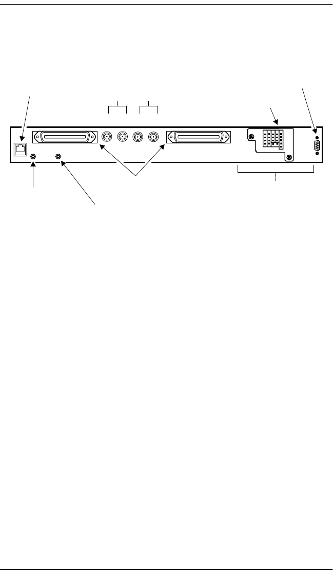
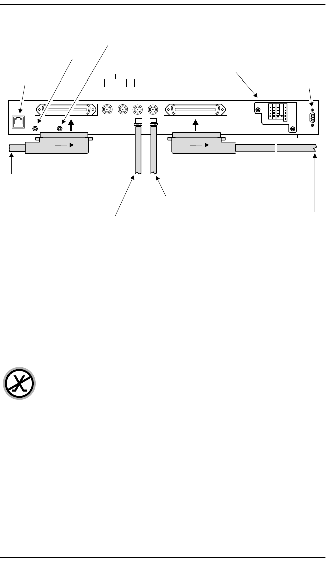
BACKPLANE
Figure 1. Backplane Interfaces (rear view)
The ThinMux chassis provides a compact 1U platform for the ThinMux
family of multiplexers with the following interconnects:
•One 10/100BASE-T Ethernet (IEEE 802.3)
•Two 64-pin female receptacle connectors for T1/E1 transmit/receive,
chassis-shielded
•Four 75ΩBNC connectors for DS3/STS-1 transmit/receive
•Four wire-wrap 0.045-inch pins for Building Integrated Timing Supply
(BITS) A and B
•Four wire-wrap 0.045-inch pins for T1 or E1 test access, transmit/receive
•Four wire-wrap 0.045-inch pins for Visible (VIS) and Audible (AUD)
alarms (dry relay contacts) which are normally open (NO) discrete
alarms
•Five wire-wrap 0.045-inch pins for discrete alarms (solid sate relay
contacts): Far End, Minor, Major, and Critical
•Five screw connectors for -48V dual power
•One DB-9 connector for RS-232 communication
ESD strap input
DS3 or STS-1
connectors DB-9 craft port
connector
RJ-45 Ethernet
10/100BASE-T
connector Line 1
Tx
Line 2
Rx Tx Rx
BITS A and B, test access
(visual, audible, and discrete
alarm wire-wrap pins)
Chassis ground
32-pair (female) connectors - T1, E1
(left Rx, right Tx)
-48 Vdc battery supply
screw connectors
(common access panel)
Test
Access CRIT
VIS CRIT
AUD
Bits Alarm
B-
B+
A-
A+
TTIP
TRING
RTIP
RRING Frame
GND Frame
GND
NO NO
COM COM
NC NC
FE
MIN
MAJ
CRIT
COM
RTN B]
-48 B
RTN A
-48 A
FGND
DB-9 craft port
connector
Craft
RS-232

LTPH-UM-1088-02, Issue 2 External Interfaces
ThinMux Chassis January 3, 2002 3
EXTERNAL INTERFACES
The ThinMux chassis provides the following interfaces:
•T1/E1
•T1/E1 Test
•RS-232
•10/100BASE-T Ethernet
•Discrete alarms
T1/E1 INTERFACE
There are two female 32-pair connectors to access 28 T1 (or 21 E1) lines for
intra-building connection; no protection is provided on the backplane. One
connector is for transmission, the other is for reception. Each port is routed to
both multiplexers (A and B) for transmit and receive. See “Appendix A - Pin
Assignments” on page 14 for interface pinout description.
T1/E1 TEST INTERFACE
The four-wire test interface can be routed to any of the 28 T1 (or 21 E1)
low-speed T1/E1 ports. It can be used to monitor the line or to look toward
the network or subscriber drop. The four signals are accessed through
four 0.045-inch wire-wrap pins. (For more information about the wire-wrap
pins, see “Connect Test Access” on page 9.)
A shielded 32-pair cable should be used and grounded at
either the frame or chassis. The ground connection is done at
one end of the cable only to avoid ground loops.

External Interfaces LTPH-UM-1088-02, Issue 2
4 January 3, 2002 ThinMux Chassis
RS-232 CRAFT INTERFACE
Communication with the ThinMux STS-1 and ThinMux DS3 central
processors occur through a standard grounded DB-9 connector (RS-232 Data
Communication Equipment interface).
Signals are routed to both multiplexers, and the transmitter of the inactive
multiplexer remains in a tristate mode. Pin 5 is the digital ground of all digital
components (both multiplexers). See Table 3 on page 17 for interface pinout
description.
10/100BASE-T ETHERNET INTERFACE
Communication with the multiplexer (STS-1 or DS3) central processors
occurs through the standard grounded RJ-45 10/100BASE-T interface for
metallic chassis. Similar to the RS-232 interface, signals are routed to both
multiplexers; the transmitter of the inactive multiplexer remains in a tristate
mode. See Table 4 on page 17 for interface pinout description.
DISCRETE ALARMS
In addition to the various interfaces supplied by the ThinMux chassis, the
common access panel (see Figure4onpage8) provides access for discrete
alarm wiring.
The discrete alarms connection is provided by 0.045-inch wire-wrap pins
located on the rear of the chassis (see Figure 1 on page 2). The signals are
routed to the multiplexers, where the logic functions are performed. Critical
VIS and AUD alarms comprise dry contacts for telemetry applications. The
alarms have an independent common connection (serial COM port) to relays;
normally open (NO) is provided. Current is limited to 0.5A when a maximum
temperature rise of 20°C on traces is desired (as per MIL-STD-275C).
When using a legacy HXU-358 multiplexer, the CRIT VIS, CRIT AUD, and
Alarm pins must be left unconnected. For all other multiplexers, these pins
may be used as needed.
Other alarms (FE, MIN, MAJ, and CRIT) share the same COM, and only
normally open contact is provided as shown in Figure4onpage8. Contact
closure is made using a solid-state relay photo Metal-Oxide Semiconductor

LTPH-UM-1088-02, Issue 2 Installation
ThinMux Chassis January 3, 2002 5
Field-Effect Transistor (MOSFET). When set to ON, resistance is 35Ωat
85°C (worst case). The switched current must be less than 80 mA, and the
switched voltage must be less than 135V. If a coil relay or other inductive
load is used, a protection diode must be connected between the alarm signal
and the COM signal to prevent damage to the solid state relay. ADC does not
provide the diode with the ThinMux chassis. The diode must be purchased
separately. Use Motorola diode part number 1N4004 or equivalent.
BATTERY SUPPLY
The battery supply terminals are located on the rear of the chassis under the
common access panel (see Figure 1 on page 2). Five AWG 16 wires connect
the Return B, -48B, Return A, -48A, and Frame Ground to the power source.
To wire power A and B inputs, attach A and B power leads from the fuse
panel or office battery to the appropriate screw connector on the terminal
block. For more information, refer to “Connecting Power” on page 10.
INSTALLATION
Before installing the ThinMux Chassis, visually check its
packaging to ensure that it has sustained no shipping
damage. Immediately report any damage to the shipping
agent. See “Appendix C - Product Support”on page 19.
Installation LTPH-UM-1088-02, Issue 2
6 January 3, 2002 ThinMux Chassis
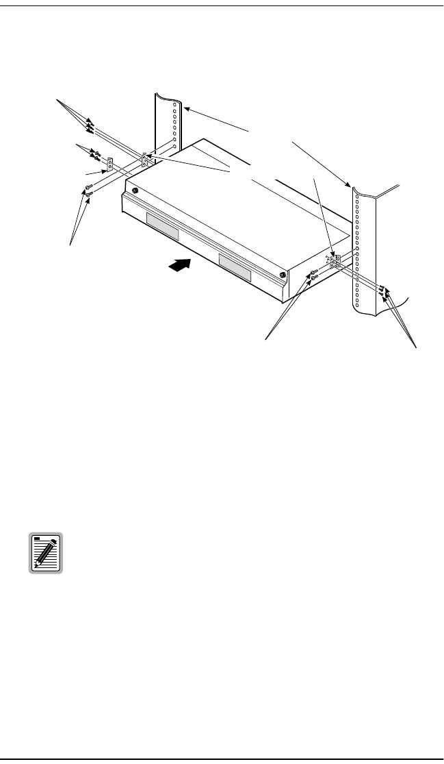
MOUNTING THE CHASSIS
Figure 2. ThinMux Chassis in a CO Rack
1Install a mounting bracket on each side of the ThinMux chassis using the
three screws provided for each bracket (8-32 x 5/16 screws) as shown in
Figure 2. (Mounting brackets and screws are contained in the installation
kit.)
2Install ESD input bracket on front left side of the chassis.
3Align the chassis mounting bracket holes with the rack’s vertical
mounting holes. Mount the chassis in the rack. Install two
12-24 x 1/2screws in each bracket and secure the chassis to the rack.
Two sets of mounting brackets are supplied to fit 19-inch or
23-inch racks with standard EIA-hole spacing (1/2 inch).
Optional brackets with WECO-hole spacing (1 inch) are
available (ACE-MK1).
CO rack
Two 12-24 x / screws
1
2
Three 8-32 x / screws
5
ESD input bracket
Two 6-32 x / screws
14
Three 8-32 x / screws
516
Mounting brackets
Two 12-24 x / screws
1
2
16
LTPH-UM-1088-02, Issue 2 Installation
ThinMux Chassis January 3, 2002 7
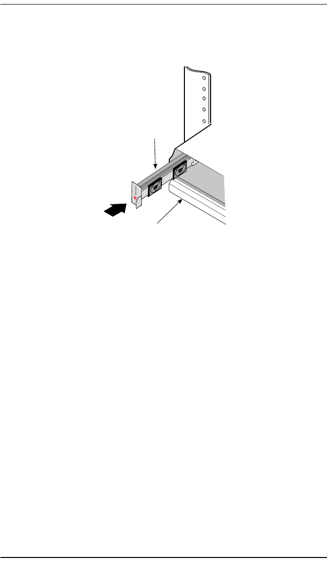
INSTALLING THE FAN MODULE (FB1)
Figure 3. Installing the Fan Module (FB1)
1Unwrap the enclosed fan module.
2Align the fan with the slot located on the left side of the chassis and slide
the fan in as shown in Figure 3.
3Insert the fan module until the connector is firmly seated in the
backplane.
Fan module
ThinMux chassis
Installation LTPH-UM-1088-02, Issue 2
8 January 3, 2002 ThinMux Chassis
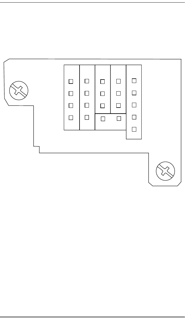
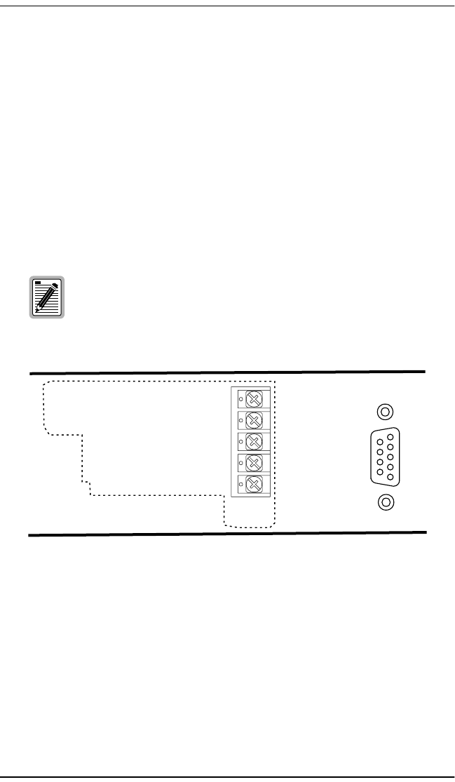
WIRING THE COMMON ACCESS PANEL
1Unscrew the common access panel hold-down lugs and remove the cover
(see Figure 4).
Figure 4. Wire-Wrap Pin Positions/Common Access Panel (rear view)
Connect a BITS Timing Source
2Determine if you require a BITS timing source connection to the chassis;
if so, the chassis must first have a line termination prior to chassis
connection.
The BITS concept is used for interoffice synchronization distribution.
Each line source, Bits A and Bits B, must be terminated. ADC provides
this termination through external termination blocks (product catalog
TERM-100) placed on wire-wrap terminal posts on the rear of the
ThinMux chassis as shown in Figure 5 on page 9.
Test
Access CRIT
VIS CRIT
AUD
Bits Alarm
B-
B+
A-
A+
TTIP
TRING
RTIP
RRING Frame
GND Frame
GND
NO NO
COM COM
NU NU
FE
MIN
MAJ
CRIT
COM
LTPH-UM-1088-02, Issue 2 Installation
ThinMux Chassis January 3, 2002 9
Figure 5. Installing Line Terminators
3Install the BITS terminating blocks (catalog number TERM-100),
provided in the installation kit, between the Bits A+, A- and B+, B- posts.
4Connect Bits A and Bits B posts to your Synchronous Optical Network
(SONET) clock synchronization source (SONET minimum clock or
better). Use a frame ground post as a shield, if needed.
Connect Test Access
5Connect the Test Access TTIP, TRING, RTIP, RING, and Frame GND
posts to the external test head.
JP12
B-
B+
A-
A+
Termination blocks
(TERM-100 part number 1178533)
Wire-wrap pin
Terminator PCB
Terminator resistor
Chassis backplane
*Install the 100 termination block with the
resistor facing towards the backplane.
Ω
Side view of
termination block*
JP7
Test
Access CRIT
VIS CRIT
AUD
Bits Alarm
B-
B+
A-
A+
TTIP
TRING
RTIP
RRING Frame
GND Frame
GND
NO NO
COM COM
NC NC
FE
MIN
MAJ
CRIT
COM
RTN B]
-48 B
RTN A
-48 A
FGND
Craft
RS-232
Installation LTPH-UM-1088-02, Issue 2
10 January 3, 2002 ThinMux Chassis
Connect Alarms
6Connect the alarm relay wires from the CO alarm center to the posts of
the Visible Alarm (CRIT. VIS—NO and COM), Audible Alarm (CRIT.
AUD—NO and COM) and Alarm (FE, MIN, MAJ, CRIT, and COM).
Follow the CO site instructions for connecting alarm relays. The visible
and audible alarm relays do not have an NC (normally closed) position.
7Connect a 16 AWG chassis ground cable to the ground (GND) post.
CONNECTING POWER
Figure 6. Battery Supply Connector (rear view)
1Connect 16 AWG cables to the -48V A, B, and RTN terminals.
2Connect the other end of the cables to CO battery supply and RTN
terminals.
3Apply power and check the voltage.
4Reinstall the common access panel and screw in the hold-down lugs.
The fuse rating for the ThinMux chassis is 2A.
RTN B
-48 B
RTN A
-48 A
FGND
LTPH-UM-1088-02, Issue 2 Installation
ThinMux Chassis January 3, 2002 11
INSTALLING DS3 OR STS-1 INTERFACE CABLES
After mounting the chassis to the CO rack, select the appropriate interface for
cable installation. (For information regarding multiplexer configuration and
operation, refer to the specific multiplexer user manual.)
The ThinMux chassis DC power supply feeds must be
connected to either (1) -48 Vdc Safety Extra Low Voltage
(SELV) sources or (2) -48 Vdc sources that are electrically
isolated from the AC sector and reliably connected to earth.
The source’s fault current capacity shall be lower than 50A,
or an appropriate overcurrent protection, rated 5A, must be
provided on each -48 Vdc conductor. The overcurrent
protection can also be used as a cutoff switch if another
disconnect device is not installed.
The ThinMux chassis is configured for redundant power.
The A and B battery sources are independently connected
to each multiplexer. In the event of a loss of power from
one of the sources, an alarm is reported by the active
multiplexer. Power is continually supplied to both slots in
the chassis.
When installing components, wear an antistatic wrist strap.
Avoid touching components on the circuit board.
Installation LTPH-UM-1088-02, Issue 2
12 January 3, 2002 ThinMux Chassis
Figure 7. DS3 or STS-1 Shelf Configuration
1Connect the 32-pair shielded cable, with amphenol male connector
coming from the cross-connect, to the DSX-1 input (Rx) as shown in
Figure 7.
2Connect the 32-pair shielded cable, with amphenol male connector going
to the cross-connect, to the DSX-1 output (Tx).
3Connect the DS3/STS-1 coaxial cable for data coming from the
DS3/STS-1 network to Line 1 Rx.
The metallic telecommunication interface should not be routed
from the building premises unless connected to
telecommunication devices providing primary and secondary
protection.
ESD strap input
DS3 or STS-1 (Out)
DS3 or STS-1 (In)
Common access panel
Craft port
Ethernet
10/100BASE-T
Line 1
Tx
Line 2
DSX-1 output (transmit)
to cross-connect
Rx Tx Rx
DSX-1 input (receive)
from cross-connect
Chassis ground
Alarms, p
and frame ground
ower,
Test
Access CRIT
VIS CRIT
AUD
Bits Alarm
B-
B+
A-
A+
TTIP
TRING
RTIP
RRING Frame
GND Frame
GND
NO NO
COM COM
NC NC
FE
MIN
MAJ
CRIT
COM
RTN B]
-48 B
RTN A
-48 A
FGND
Craft
RS-232

LTPH-UM-1088-02, Issue 2 Installation
ThinMux Chassis January 3, 2002 13
4Connect the DS3/STS-1 coaxial cable for data going to the DS3/STS-1
network to Line 1 Tx.
5Connect the Ethernet port to a LAN, if required.
6Connect a VT100 maintenance terminal to the craft port, if required.
Appendix A - Pin Assignments LTPH-UM-1088-02, Issue 2
14 January 3, 2002 ThinMux Chassis
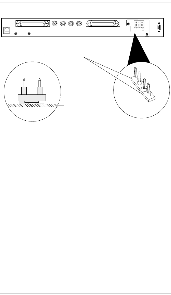
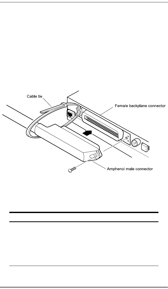
APPENDIX A-PIN ASSIGNMENTS
T1/E1 INTERFACE
Figure 8 shows the male T1/E1 amphenol cable connector connecting to the
female T1/E1 connector located on the backplane of the ThinMux chassis.
Table 1 on page 14 and Table 2 on page 16 describe the pin assignments for
transmit and receive.
Figure 8. Male Cable Connector Into Female Backplane Connector
Table 1. T1/E1 Receive Pin Assignments
Pin Number Description Pin Number Description
1DSX_RX_RING1 33 DSX_RX_TIP1
2DSX_RX_RING2 34 DSX_RX_TIP2
3DSX_RX_RING3 35 DSX_RX_TIP3
4DSX_RX_RING4 36 DSX_RX_TIP4
5DSX_RX_RING5 37 DSX_RX_TIP5
6DSX_RX_RING6 38 DSX_RX_TIP6
Continued

LTPH-UM-1088-02, Issue 2 Appendix A - Pin Assignments
ThinMux Chassis January 3, 2002 15
7DSX_RX_RING7 39 DSX_RX_TIP7
8DSX_RX_RING8 40 DSX_RX_TIP8
9DSX_RX_RING9 41 DSX_RX_TIP9
10 DSX_RX_RING10 42 DSX_RX_TIP10
11 DSX_RX_RING11 43 DSX_RX_TIP11
12 DSX_RX_RING12 44 DSX_RX_TIP12
13 DSX_RX_RING13 45 DSX_RX_TIP13
14 DSX_RX_RING14 46 DSX_RX_TIP14
15 DSX_RX_RING15 47 DSX_RX_TIP15
16 DSX_RX_RING16 48 DSX_RX_TIP16
17 DSX_RX_RING17 49 DSX_RX_TIP17
18 DSX_RX_RING18 50 DSX_RX_TIP18
19 DSX_RX_RING19 51 DSX_RX_TIP19
20 DSX_RX_RING20 52 DSX_RX_TIP20
21 DSX_RX_RING21 53 DSX_RX_TIP21
22 DSX_RX_RING22 54 DSX_RX_TIP22
23 DSX_RX_RING23 55 DSX_RX_TIP23
24 DSX_RX_RING24 56 DSX_RX_TIP24
25 DSX_RX_RING25 57 DSX_RX_TIP25
26 DSX_RX_RING26 58 DSX_RX_TIP26
27 DSX_RX_RING27 59 DSX_RX_TIP27
28 DSX_RX_RING28 60 DSX_RX_TIP28
29 N/C 61 N/C
30 N/C 62 N/C
31 N/C 63 N/C
32 N/C 64 Chassis Ground
Table 1. T1/E1 Receive Pin Assignments (Continued)
Pin Number Description Pin Number Description

Appendix A - Pin Assignments LTPH-UM-1088-02, Issue 2
16 January 3, 2002 ThinMux Chassis
Table 2. T1/E1 Transmit Pin Assignments
Pin Number Description Pin Number Description
1DSX_TX_RING1 33 DSX_TX_TIP1
2DSX_TX_RING2 34 DSX_TX_TIP2
3DSX_TX_RING3 35 DSX_TX_TIP3
4DSX_TX_RING4 36 DSX_TX_TIP4
5DSX_TX_RING5 37 DSX_TX_TIP5
6DSX_TX_RING6 38 DSX_TX_TIP6
7DSX_TX_RING7 39 DSX_TX_TIP7
8DSX_TX_RING8 40 DSX_TX_TIP8
9DSX_TX_RING9 41 DSX_TX_TIP9
10 DSX_TX_RING10 42 DSX_TX_TIP10
11 DSX_TX_RING11 43 DSX_TX_TIP11
12 DSX_TX_RING12 44 DSX_TX_TIP12
13 DSX_TX_RING13 45 DSX_TX_TIP13
14 DSX_TX_RING14 46 DSX_TX_TIP14
15 DSX_TX_RING15 47 DSX_TX_TIP15
16 DSX_TX_RING16 48 DSX_TX_TIP16
17 DSX_TX_RING17 49 DSX_TX_TIP17
18 DSX_TX_RING18 50 DSX_TX_TIP18
19 DSX_TX_RING19 50 DSX_TX_TIP19
20 DSX_TX_RING20 52 DSX_TX_TIP20
21 DSX_TX_RING21 53 DSX_TX_TIP21
22 DSX_TX_RING22 54 DSX_TX_TIP22
23 DSX_TX_RING23 55 DSX_TX_TIP23
24 DSX_TX_RING24 56 DSX_TX_TIP24
25 DSX_TX_RING25 57 DSX_TX_TIP25
26 DSX_TX_RING26 58 DSX_TX_TIP26
27 DSX_TX_RING27 59 DSX_TX_TIP27
28 DSX_TX_RING28 60 DSX_TX_TIP28
29 N/C 61 N/C
30 N/C 62 N/C
31 N/C 63 N/C
32 N/C 64 Chassis Ground

LTPH-UM-1088-02, Issue 2 Appendix A - Pin Assignments
ThinMux Chassis January 3, 2002 17
RS-232 CRAFT INTERFACE
10/100BASE-T ETHERNET INTERFACE
Table 3. RS-232 Craft Interface Pin Assignments
Pin Number Description
1NC
2TX
3RX
4DSR
5Digital ground
6DTR
7NC
8NC
9NC
Table 4. Ethernet 10/100BASE-T Pin Assignments
Pin Number Description
1DATA_TRANSMIT+
2DATA_TRANSMIT-
3DATA_RECEIVE+
4NC
5NC
6DATA_RECEIVE-
7NC
8NC

Appendix B - Specifications LTPH-UM-1088-02, Issue 2
18 January 3, 2002 ThinMux Chassis
APPENDIX B-SPECIFICATIONS
Power
Input Voltage Range -60 Vdc to -42.5 Vdc
Fusing 2A
Environmental
Operating temperature -40°F to +149°F (-40°C to +65°C)
Operating humidity 10% to 95%, non-condensing
Dimensions
Height: 1.75 in.
Width: 17.35 in.
Depth: 12.0 in.
Weight: < 10 lbs. (fully configured)
Network Interfaces DS3 and STS-1 (using a ThinMux multiplexer)
Rear Panel Interfaces
DS3/STS-1 4 BNC, male
DS1/E1 32-pair shielded cable with amphenol male connector
Craft DB-9 female
Ethernet/Telnet RJ-45
Alarm Contacts Wire-wrap pins, FE, MIN, MAJ, CRIT, COM (NO)
Audible Alarm Wire-wrap pins, COM (NO)
Visible Alarm Wire-wrap pins, COM (NO)
Test Access Wire-wrap pins, TTIP, TRING, RTIP, RRING, Frame GND
Power Dual screw terminals
Bits A and B Wire-wrap pins A+, A-, B+, B-, shield, RtipA, RringA, RtipB,
RringB, shield

LTPH-UM-1088-02, Issue 2 Appendix C - Product Support
ThinMux Chassis January 3, 2002 19
APPENDIX C-PRODUCT SUPPORT
ADC Customer Service Group provides expert pre-sales and post-sales
support and training for all its products.
Technical support is available 24 hours a day, 7 days a week by contacting
the ADC Technical Assistance Center (TAC).
Sales Assistance
800.366.3891 ext. 73000 (USA and
Canada) or 952.917.3000
Fax: 952.917.3237
•Quotation Proposals
•Ordering and Delivery
•General Product Information
Systems Integration
800.366.3891, ext. 73000 (USA and
Canada) or 952.917.3000
•Complete Solutions (from concept to
installation)
•Network Design and Integration Testing
•System Turn-Up and Testing
•Network Monitoring (upstream or downstream)
•Power Monitoring and Remote Surveillance
•Service/Maintenance Agreements
•Systems Operation
BIA Technical Assistance Center
800.638.0031 or 714.730.3222
Fax: 714.730.2400
Email: wsd_support@adc.com
•Technical Information
•System/Network Configuration
•Product Specification and Application
•Training (product-specific)
•Installation and Operation Assistance
•Troubleshooting and Repair/Field Assistance
Online Technical Support •www.adc.com/Knowledge_Base/index.jsp
Online Technical Publications •www.adc.com/library1/
Product Return Department
800.366.3891 ext. 73748 (USA and
Canada) or 952.917.3748
Fax: 952.917.3237
Email: repair&return@adc.com
•ADC Return Material Authorization (RMA)
number and instructions must be obtained
before returning products.
All 800 lines are toll-free in the USA and Canada.

Appendix D - Abbreviations LTPH-UM-1088-02, Issue 2
20 January 3, 2002 ThinMux Chassis
APPENDIX D-ABBREVIATIONS
A
AWG: American Wire Gauge
B
BITS: Building Integrated Timing
Supply
BNC: Bayonet-Locking Connector
C
CO: Central Office
COM: Communications Port on a PC
(serial port)
CRIT: Critical Alarm
D
DCE: Data Communication Equipment
DS3: Digital Signal, Level 3
E
ELV: Extra Low Voltage
ESD: Electrostatic Discharge
F
FE: Far End
L
LAN: Local Area Network
M
MAJ: Major Alarm
MIN: Minor Alarm
MOSFET: Metal-Oxide Semiconductor
Field-Effect Transistor
N
NO: Normally Open
R
RX: Receive
S
SELV: Safety Extra Low Voltage
STS: Synchronous Transport Signal,
Level 1
T
TX: Transmit

CERTIFICATION AND WARRANTY
FCC CLASS ACOMPLIANCE
This equipment has been tested and found to comply with the limits for a Class A
digital device, pursuant to Part 15 of the FCC Rules. These limits are designed to
provide reasonable protection against harmful interference when the equipment is
operated in a commercial environment. This equipment generates, uses, and can
radiate radio frequency energy and, if not installed and used in accordance with the
instruction manual, may cause harmful interference to radio communications.
Operation of this equipment in a residential area is likely to cause harmful interference
in which case the user will be required to correct the interference at his own expense.
LIMITED WARRANTY
ADC DSL Systems, Incorporated (“ADC”) warrants that, for a period of sixty (60)
months from the date of shipment, the hardware portion of its products will be free of
material defects and faulty workmanship under normal use. ADC's obligation, under
this warranty, is limited to replacing or repairing, at ADC's option, any such hardware
product which is returned during the 60-month warranty period per ADC's instructions
and which product is confirmed by ADC not to comply with the foregoing warranty.
ADC warrants that, for a period of 90 days from the date of purchase, the software
furnished with its products will operate substantially in accordance with the ADC
published specifications and documentation for such software. ADC’s entire liability
for software that does not comply with the foregoing warranty and is reported to ADC
during the 90-day warranty period is, at ADC’s option, either (a) return of the price
paid or (b) repair or replace of the software. ADC also warrants that, for a period of
thirty (30) days from the date of purchase, the media on which software is stored will
be free from material defects under normal use. ADC will replace defective media at
no charge if it is returned to ADC during the 30-day warranty period along with proof
ofthedateofshipment.
The transportation charges for shipment of returned products to ADC will be prepaid
by the Buyer. ADC will pay transportation charges for shipment of replacement
products to Buyer, unless no trouble is found (NTF), in which case the Buyer will pay
transportation charges.
ADC may use reconditioned parts for such repair or replacement. This warranty does
not apply to any product which has been repaired, worked upon, or altered by persons
not authorized by ADC or in ADC's sole judgment has been subjected to misuse,
accident, fire or other casualty, or operation beyond its design range.

Repaired products have a 90-day warranty, or until the end of the original warranty
period—whichever period is greater.
ADC DISCLAIMS ALL OTHER WARRANTIES, EITHER EXPRESS OR
IMPLIED, INCLUDING BUT NOT LIMITED TO IMPLIED WARRANTIES OF
MERCHANTABILITY AND FITNESS FOR A PARTICULAR PURPOSE, WITH
RESPECT TO ITS PRODUCTS AND ANY ACCOMPANYING WRITTEN
MATERIALS. FURTHER, ADC DOES NOT WARRANT THAT SOFTWARE
WILL BE FREE FROM BUGS OR THAT ITS USE WILL BE UNINTERRUPTED
OR REGARDING THE USE, OR THE RESULTS OF THE USE, OF THE
SOFTWARE IN TERMS OF CORRECTNESS, ACCURACY, RELIABILITY OR
OTHERWISE.
MODIFICATIONS
Any changes or modifications made to this device that are not expressly approved by
ADC DSL Systems, Inc. voids the user's warranty.
All wiring external to the products should follow the provisions of the current edition
of the National Electrical Code.
SAFETY STANDARDS COMPLIANCE
The ThinMux chassis has been tested and verified to comply with the applicable
sections of the following safety standards:
•GR 63-CORE - Network Equipment-Building System (NEBS) Requirements:
Physical Protection
•GR 1089-CORE - Electromagnetic Compatibility and Electrical Safety Generic
Criteria for Network Telecommunications Equipment
•Bi-national standard, UL-1950/CSA-C22.2 No. 950-95; Safety of Information
Technology Equipment
For technical assistance, refer to “Appendix C - Product Support”on page 19.

ADC DSL Systems, Inc.
14402 Franklin Avenue
Tustin, CA 92780-7013
Tel: 714.832.9922
Fax: 714.832.9924
Technical Assistance
Tel: 800.638.0031
Tel: 714.730.3222
Fax: 714.730.2400
DNV C ertificatio n, Inc.
REGISTERED FIRM
ISO 9001/TL 9000
DOCUMENT: LTPH-UM-1088-02, ISSUE 2
´,$;¶5}¨
1204275
