ADInstruments NZ HU11 Short range telemetry transmitter User Manual
Millar Instruments Ltd Short range telemetry transmitter
User Manual


User Manual for Millar Mouse Telemetry MKT0006/A

User Manual for Millar Mouse Telemetry MKT0006/A
Contents
Important Information ............................................................................................................... 1
Disclaimer ......................................................................................................................... 1
Warranty ........................................................................................................................... 1
FCC Compliance .............................................................................................................. 2
Introduction .............................................................................................................................. 4
Telemetry System Components ............................................................................................... 5
Quick Start Guide ..................................................................................................................... 6
Configurator System Setup ...................................................................................................... 7
Configurator Software Installation ..................................................................................... 7
Connecting the Configurator ........................................................................................... 10
Configurator Software - Overview ................................................................................... 11
tBase - Overview .................................................................................................................... 13
tBase Laboratory Setup .................................................................................................. 14
Status lights .................................................................................................................... 14
Analog Outputs and Calibration Values .......................................................................... 15
The Mouse telemeter ............................................................................................................. 16
Channel and serial numbers ........................................................................................... 16
System setup and configuration ............................................................................................. 17
Changing telemeter Channel .......................................................................................... 18
Changing tBase Channel ................................................................................................ 20
Positioning the telemeter during surgery ................................................................................ 22
Telemeter Care and Handling ................................................................................................ 24
Diagnostics ............................................................................................................................. 25
tBase Technical Specifications .............................................................................................. 26
Telemeter Technical Specifications ....................................................................................... 27
Frequently Asked Questions........ .......................................................................................... 28
Contact Information ................................................................................................................ 28
To all users;
We pride ourselves in partnering with you to achieve excellent results. If you have any questions
related to the operation of your system, please contact us at support@millar.com
We are here to help.
Contact Information
US Head Office
New Zealand Office
Houston, Texas
Toll free (USA only) 1 800 669 2343
TEL: +1 832 667 7000
FAX: +1 713 714 8497
Auckland, New Zealand
TEL: +64 9 367 7126
FAX: +64 9 367 7157
EMAIL support@millar.com or sales@millar.com
WEB www.millar.com

User Manual for Millar Mouse Telemetry MKT0006/A

User Manual for Millar Mouse Telemetry Systems MKT0006/A Page 1
Important Information
Disclaimer
Millar believes that information in this user manual is correct at the time of publishing. In the event errors may exist, Millar
reserves the right to make changes to future editions without notice to holders of this edition. The reader should consult
Millar if errors are suspected. In no event shall Millar be held liable for damages arising out of the use of this document
or information contained within. Except as specified below, Millar makes no warranties, express or implied, and specifically
disclaims any warranty of the products fitness for a particular purpose.
The customer’s right to recover damages by fault or negligence of Millar are limited to the amount paid by the customer.
Any action against Millar must be brought within one year after the cause of action accrues. Millar will not be held liable
for any loss of data, research funding or profits and neither will it be liable for incidental or consequential damages even
if advised of the possibility thereof.
Millar expresses that its products are for research purposes only. They are not designed with components and
testing intended for use in medical treatment or diagnosis of humans or animals and doing so may result in
serious harm.
Warranty
Telemeter Warranty
Millar warrants that at the time of sale and shipment to the original Purchaser, Millar mouse telemeters shall be free from
defects in material and workmanship. This warranty voids on first use of the telemeter. If there is such a defect, Millar
will, at no charge, replace the equipment as appropriate.
Telemetry Hardware Warranty
Millar warrants that at the time of sale to the original Purchaser, the telemetry hardware (excluding telemeters – see above)
shall be free from defects in materials and workmanship for a period of one (1) year from its date of shipment to the original
purchaser. If there is such a defect, Millar will, at no charge and at its option, either repair or replace the equipment as
appropriate.
Should the hardware become damaged after expiration of the one year warranty, Millar will accept the product for a no
charge evaluation with a signed RMA (return material authorization). If repairs are required, Millar will provide a detailed
quote and lead time for the repair process. Repair work will not commence until approval is received from the customer.
As part of Millar’s continued commitment to customer support, free online, phone and email support in the use of all
telemetry equipment is available beyond all warranty periods.
The warranties above do not cover damage caused by failure to follow instructions for use, owner’s abuse, misuse or
negligence, user tampering or modifications, power failures or surges and events or accidents considered force majeure
such as flooding, fire, etc. outside the reasonable control of Millar. In no case shall liability exceed the purchase price of
the original product.
Millar provides free product evaluations during the warranty period and free return to customer shipment. All returned
products should be packed safely, preferably in original packaging, cleaned/sterilized and shipped to Millar with the RMA
number visible on the packaging and with all RMA documentation. In order to receive the highest level of support, the
customer is responsible for notifying Millar immediately of a problem within the warranty period. Following product
evaluation, Millar will replace or repair (excluding telemeters which are non-repairable) any product found to be defective
and covered within the warranty period, while operated in accordance with instructions for use and specifications.
Copyright © Millar, November 2016
This publication may not be reproduced or transmitted in any form, electronic or mechanical, including photocopying,
recording, storing in an information retrieval system, or translating, in whole or in part, without the prior written consent of
Millar.
For complete product instructions, general insights and surgical recommendations, visit millar.com and access
Millar’s free online Knowledge Center. http://millar.com/knowledge-center Millar is committed to delivering the
collaborative support you expect in facilitating scientific insight and advancing medical innovation.

Page 2 User Manual for Millar Mouse Telemetry MKT0006/A
FCC Compliance
Telemeter (MT10B)
This device complies with part 15 of the FCC Rules. Operation is subject to the following two
conditions:
1. This device may not cause harmful interference, and
2. This device must accept any interference received, including interference that may cause
undesired operation.
Note: This equipment has been tested and found to comply with the limits for a Class B digital
device, pursuant to part 15 of the FCC Rules. These limits are designed to provide reasonable
protection against harmful interference in a residential installation. This equipment generates, uses
and can radiate radio frequency energy and, if not installed and used in accordance with the
instructions, may cause harmful interference to radio communications. However, there is no
guarantee that interference will not occur in a particular installation. If this equipment does cause
harmful interference to radio or television reception, which can be determined by turning the
equipment off and on, the user is encouraged to try to correct the interference by one or more of the
following measures:
Reorient or relocate the receiving antenna.
Increase the separation between the equipment and receiver.
Connect the equipment into an outlet on a circuit different from that to which the receiver is
connected.
Consult the dealer or an experienced radio/TV technician for help.
Changes or modifications not expressly approved by Millar Inc. could void the user's authority to
operate the equipment.
TR190 Configurator
This device complies with part 15 of the FCC Rules. Operation is subject to the following two
conditions:
1. This device may not cause harmful interference, and
2. This device must accept any interference received, including interference that may cause
undesired operation.
Note: This equipment has been tested and found to comply with the limits for a Class B digital
device, pursuant to part 15 of the FCC Rules. These limits are designed to provide reasonable
protection against harmful interference in a residential installation. This equipment generates, uses
and can radiate radio frequency energy and, if not installed and used in accordance with the
instructions, may cause harmful interference to radio communications. However, there is no
guarantee that interference will not occur in a particular installation. If this equipment does cause
harmful interference to radio or television reception, which can be determined by turning the
equipment off and on, the user is encouraged to try to correct the interference by one or more of the
following measures:
Reorient or relocate the receiving antenna.
Increase the separation between the equipment and receiver.
Connect the equipment into an outlet on a circuit different from that to which the receiver is
connected.
Consult the dealer or an experienced radio/TV technician for help.
Changes or modifications not expressly approved by Millar Inc. could void the user's authority to
operate the equipment.

User Manual for Millar Mouse Telemetry Systems MKT0006/A Page 3
MT110 tBase
The Wireless Power Transfer System is FCC Part 18 Compliant
Note: This equipment has been tested and found to comply with part 18 of the FCC limits for non-
consumer equipment. These limits are designed to provide reasonable protection against harmful
interference in an industrial installation. This equipment generates uses and can radiate radio
frequency energy and, if not installed and used in accordance with the instructions, may cause
harmful interference to radio communications. However, there is no guarantee that interference will
not occur in a particular installation. If this equipment does cause harmful interference to radio or
television reception, which can be determined by turning the equipment off and on, the user is
encouraged to try to correct the interference by one or more of the following measures:
Reorient or relocate the receiving antenna.
Increase the separation between the equipment and receiver.
Connect the equipment into an outlet on a circuit different from that to which the receiver is
connected.
Consult the dealer or an experienced radio/TV technician for help.
Note: There is no required maintenance of this device from a FCC compliance perspective.
The 2.4GHz Data Transmitter is FCC Part 15 Compliant
This device complies with part 15 of the FCC Rules. Operation is subject to the following two
conditions:
1. This device may not cause harmful interference, and
2. This device must accept any interference received, including interference that may cause
undesired operation.
Note: This equipment has been tested and found to comply with the limits for a Class B digital
device, pursuant to part 15 of the FCC Rules. These limits are designed to provide reasonable
protection against harmful interference in a residential installation. This equipment generates, uses
and can radiate radio frequency energy and, if not installed and used in accordance with the
instructions, may cause harmful interference to radio communications. However, there is no
guarantee that interference will not occur in a particular installation. If this equipment does cause
harmful interference to radio or television reception, which can be determined by turning the
equipment off and on, the user is encouraged to try to correct the interference by one or more of the
following measures:
Reorient or relocate the receiving antenna.
Increase the separation between the equipment and receiver.
Connect the equipment into an outlet on a circuit different from that to which the receiver is
connected.
Consult the dealer or an experienced radio/TV technician for help.
Changes or modifications not expressly approved by Millar Inc. could void the user's authority to
operate the equipment.

Page 4 User Manual for Millar Mouse Telemetry MKT0006/A
Introduction
This User Manual contains information to help with the correct installation and basic use of the Millar
Mouse Telemetry System. It is strongly recommended that you also visit our online Knowledge
Center for more information and to view instructional videos showing telemeter implantation and
recommendations for general use and care of your system. www.millar.com/knowledge-center
The Millar Mouse Telemetry system uses a unique and efficient patented inductive power transfer
system for making long-term recordings in conscious mice (>22 g). No battery is required to
wirelessly record high quality biological signals 24/7. Telemetered mice can be housed in a single
room without the need for shielding as each mouse telemeter communicates with a tBase on one
of 40 independent transmission frequencies (Channels).
The system comprises of a telemeter, tBase and Configurator System. The mouse biopotential
telemeter measures the electrical potential (ECG, EMG, EEG) between the positive and negative
leads and transmits the data wirelessly to the tBase. The tBase provides wireless power to the
telemeter, acts as the receiver for the digital data (sampled at 2 kHz) transmitted by the telemeter
and converts it to an analog signal. The Millar Mouse Telemetry System is therefore compatible
with all acquisition systems with analog inputs. The Configurator System allocates telemeter and
tBase data transmission frequencies and provides diagnostic information on the telemeter or tBase.
Due to continual product improvement, your system may look slightly different to the images and
graphics contained in this manual. If you have any questions or need help please contact us at
support@millar.com
Key Features
Accuracy:
For long term, high frequency physiological recordings. Digital wireless recording of data with the
highest quality and signal integrity (sampling 2 kHz).
24/7:
Data can be collected 24 hours a day while the animal is on the tBase.
Versatility:
Telemeters send digital data wirelessly from within the animal to the tBase where it is converted to
an analog signal compatible with existing data acquisition systems.
Low cost of ownership:
Millar mouse telemeters are single use items which eliminates the time and cost associated with
telemeter explant and refurbishment.
Efficient housing:
Multiple animals can be housed in one location for simultaneous recordings. No specialized cages
or shielding is required as each telemeter operates independently on one of 40 transmission
frequencies.
Service & support:
Millar prides itself on being responsive to our customers’ current and future needs. We have
experienced engineers and scientists on staff to provide professional, expert and timely support and
advice.
User Manual for Millar Mouse Telemetry Systems MKT0006/A Page 5
Telemetry System Components
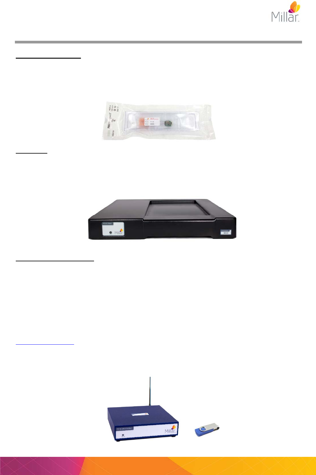
The Mouse telemeter
All telemeters are shipped individually packaged, sterile and ready for use. The telemeters will need
to be configured to a data collection Channel prior to implantation. PLEASE NOTE the telemeter
does NOT need to be removed from its packaging for Configuration. When handling the telemeter,
care must be taken not to damage the telemeter body or lead wires as telemeters are non-
repairable.
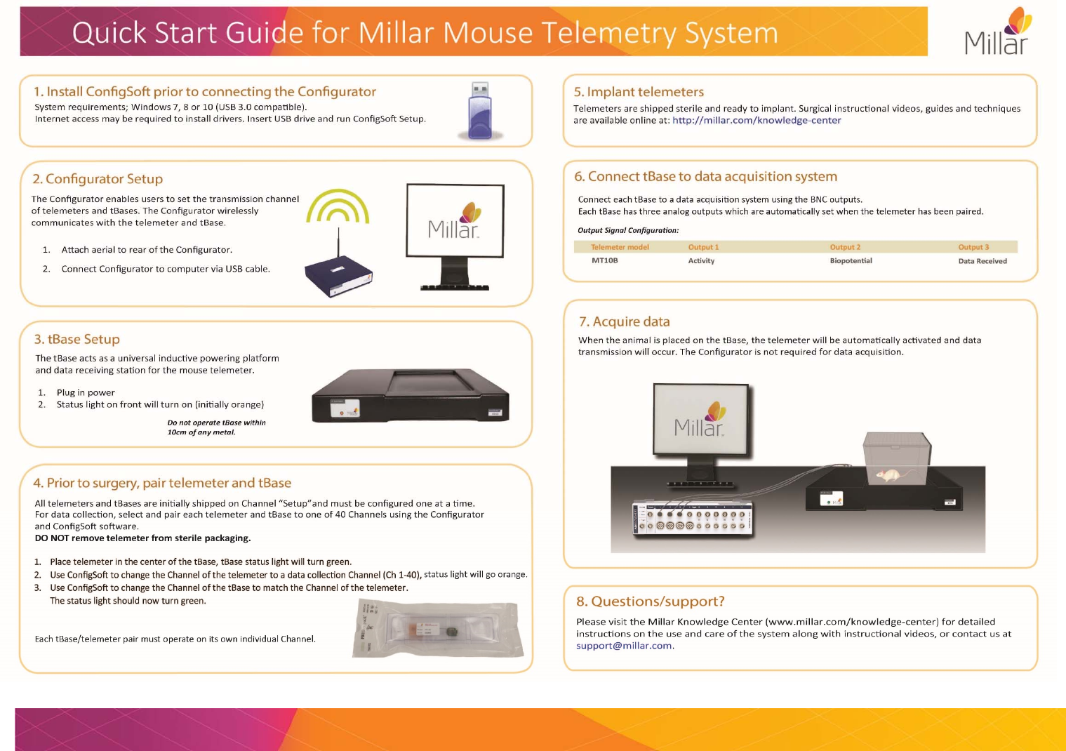
The tBase
The tBase is able to detect the location of the telemeter within the operating area to efficiently
provide power to the telemeter. For safe and normal operation of the tBase it needs to be placed
on a flat non-metallic surface. There must not be any metal or another tBase within 10 cm of the
tBase and we recommend at least a minimum of 40 cm separating distance above or below another
tBase.
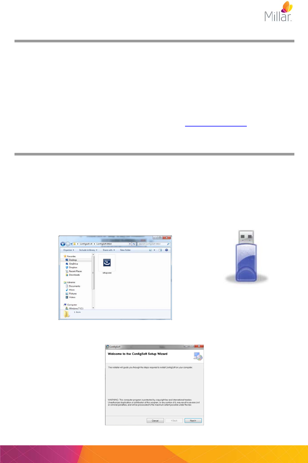
The Configurator System
The Configurator System (Configurator hardware and ConfigSoft software) wirelessly controls
mouse telemeters and tBases to:
Change/configure mouse telemeter and tBase transmission Channels (this must be done
before implantation).
Run and provide diagnostic information on mouse telemeters and tBases.
ONLY a single Configurator System is required to control all Millar (rat or mouse) telemetry systems
in a laboratory. The Configurator System is not required for data acquisition. Note: Existing Millar
rat telemetry customers with a Configurator System may only require a firmware and software
update to their Configurator for use with the mouse telemetry system. Please contact
support@millar.com for assistance.
** IMPORTANT: The ConfigSoft software supplied on the USB drive must be installed on a computer
before connecting the Configurator hardware to the computer.
User Manual for Millar Mouse Telemetry MKT0006/A Page 6
Quick Start Guide
User Manual for Millar Mouse Telemetry Systems MKT006/A Page 7
Configurator System Setup
Introduction
The Configurator System (TR190 Configurator hardware and ConfigSoft software), wirelessly
communicates with the mouse telemeters and tBases. The system allows the user to:
1) Change/configure the transmission Channel of the tBase
2) Change/configure the transmission Channel of the telemeter.
3) Run Diagnostics on telemeters and tBases.
Only a single Configurator System is required for each laboratory and it is NOT required
during data acquisition. Existing Configurator hardware in use with the Millar Rat Telemetry
Systems can be used with the Millar Mouse Telemetry System however a firmware and
ConfigSoft software upgrade may be required. Contact support@millar.com for assistance.
Configurator Software Installation
NOTE: ConfigSoft must be installed on the computer before connecting the Configurator hardware.
Existing versions of ConfigSoft must also be uninstalled prior to installation.
System requirements: Windows 7, 8 or 10. There are two separate installers 32 bit and 64 bit,
please install the version compatible with your Windows operating system. Internet connection is
necessary to access and install any drivers not already installed.
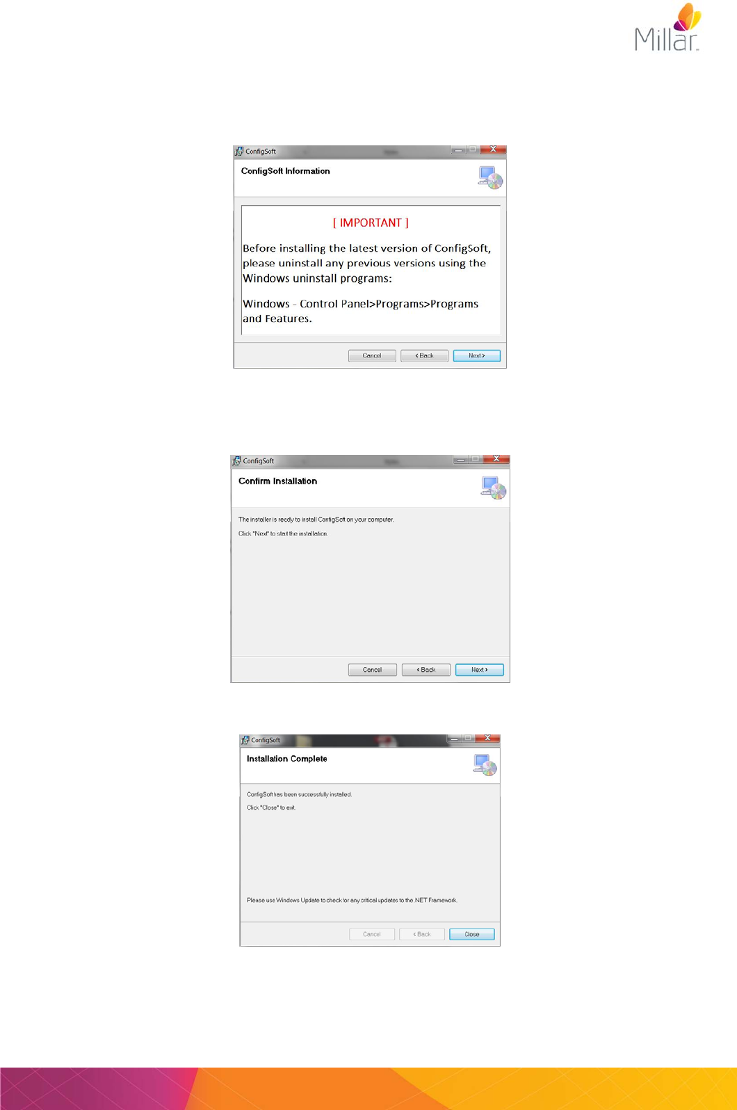
1) Connect the supplied USB drive containing ConfigSoft to your computer.
2) Open the ConfigSoft folder and go to folder “ConfigSoft 32 bit” or “ConfigSoft 64 bit” according
to your Windows Operating System.
3) Double click on “setup” to start the installation.
4) Once the welcome screen appears, follow the instructions for installation.
Page 8 User Manual for Millar Mouse Telemetry MKT0006/A
5) Previous versions of the ConfigSoft software must be removed before continuing with the
installation. If you need to remove the program, follow the instructions in this window before
clicking Next.
6) Confirm installation. Click Next
7) After the installation has been completed. Click Close.
User Manual for Millar Mouse Telemetry Systems MKT006/A Page 9
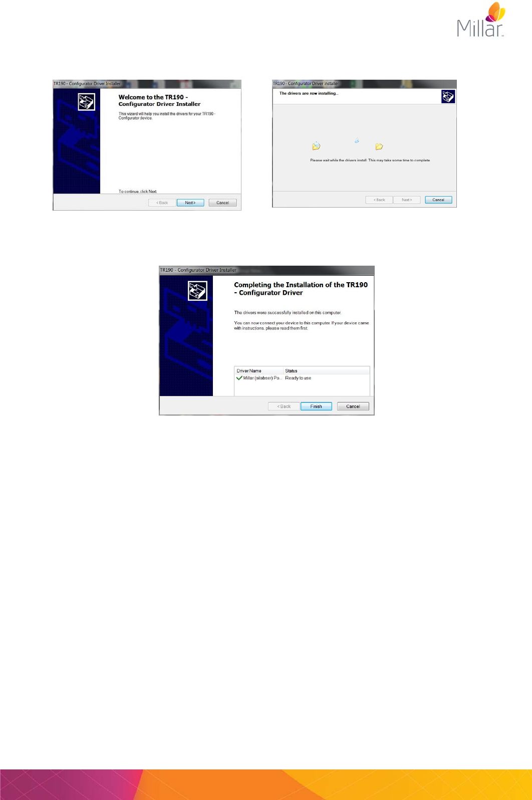
8) The following window will automatically appear to install the driver for the TR190 Configurator
if it is not already located on the computer. Click Next.
9) After successful installation of the TR190 Driver, Click Finish.
10) Installation of ConfigSoft and the TR190 Configurator drivers has been completed.
Page 10 User Manual for Millar Mouse Telemetry MKT0006/A
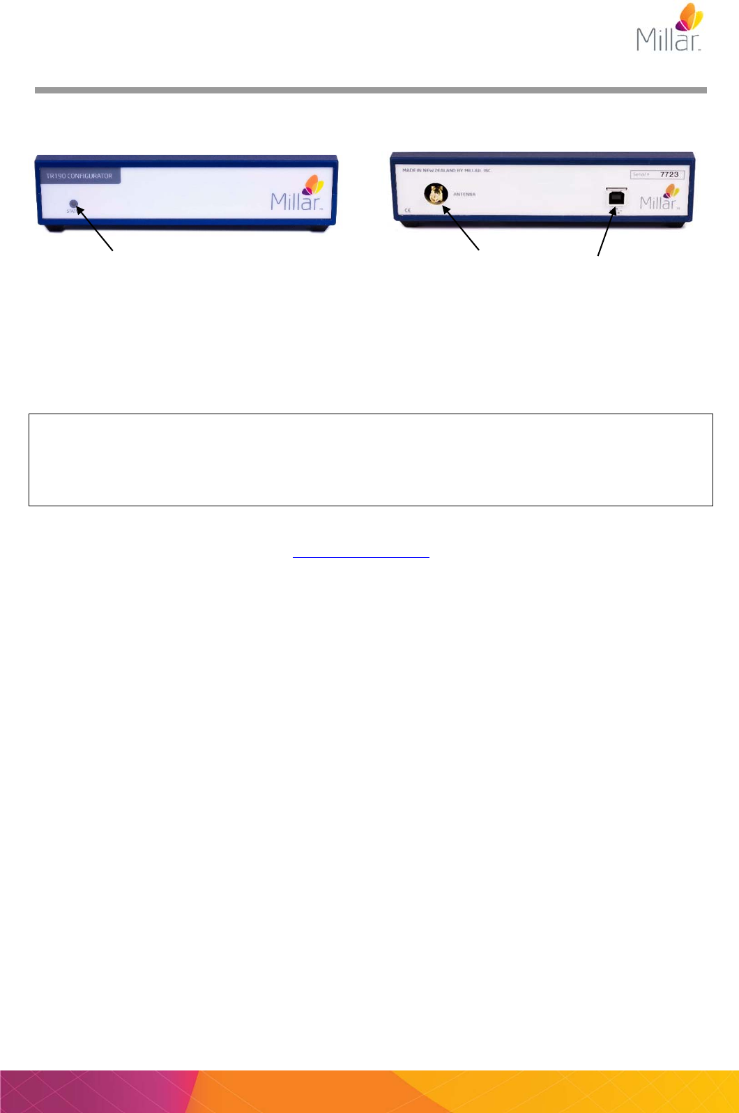
Connecting the Configurator
Front Rear
1) Attach the antenna to the rear of the Configurator.
2) After installation of ConfigSoft, connect the Configurator to the computer using the supplied
USB cable. The status light on the front of the Configurator should glow red or green indicating
that it is receiving power from the computer.
The status light on the front panel of the Configurator indicates the following information:
Off Not connected, USB cable unplugged, Configurator is off
Red Configurator is receiving power but not communicating with computer
Green Configurator is communicating with the computer
3) The computer will install any additional drivers and the status light should glow green. If there
are any problems please contact support@millar.com.
4) The Configurator System is now ready for use with all your mouse telemeters and tBases.
Status light Antenna
connection USB port
User Manual for Millar Mouse Telemetry Systems MKT006/A Page 11
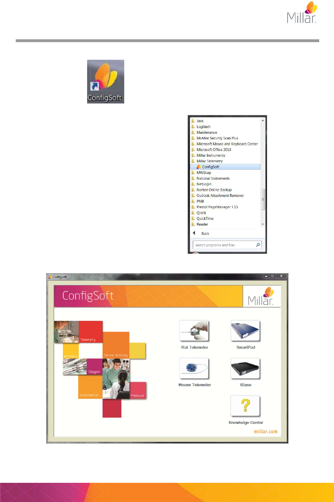
Configurator Software - Overview
ConfigSoft can be started from either the
Desktop icon
OR
Start>Programs>Millar Telemetry>ConfigSoft
Page 12 User Manual for Millar Mouse Telemetry MKT0006/A
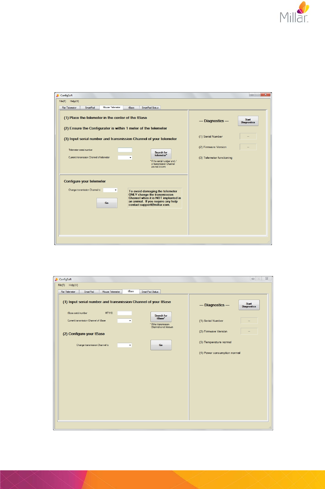
From the main menu the user has access to the:
1. Rat Telemeter (not required for the mouse telemetry system)
2. SmartPad (not required for the mouse telemetry system)
3. Mouse Telemeter
4. tBase
5. SmartPad Status (not required for the mouse telemetry system)
Mouse Telemeter Tab
tBase Tab
User Manual for Millar Mouse Telemetry Systems MKT006/A Page 13
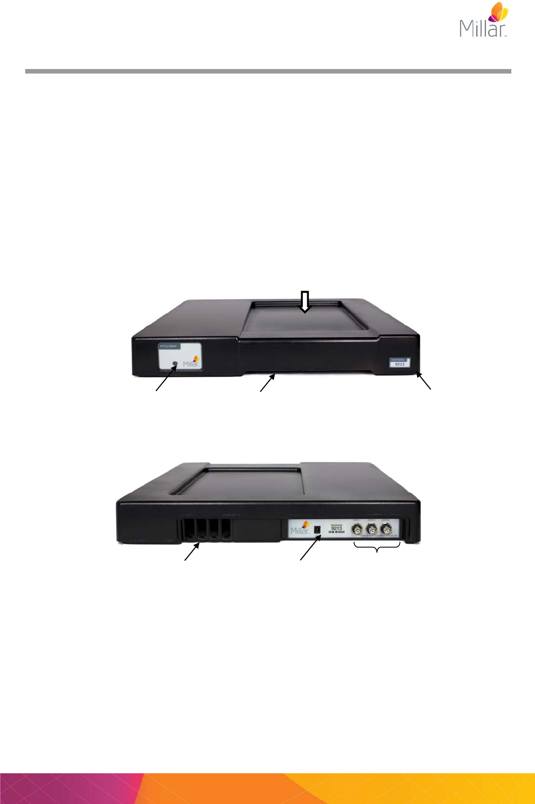
tBase - Overview
The tBase is both a wireless power supply and receiver for the mouse telemeter. The top of the
tBase has an indent (335mm (L) x 190mm (W) x 10mm (D)) which a mouse cage must be positioned
in for the best access to the inductive power field. Only use cages that fit into the indent area with
the cage base in contact with the surface of the indent.
The tBase generates an inductive power field which extends approximately 7cm above the surface
of the indent. When the mouse telemeter is within the tBase power field, the telemeter will be
powered and data recorded. Only telemeters paired on the same transmission Channel as the
tBase will communicate, be powered and transmit data efficiently and accurately.
No data will be recorded when the telemeter is not in the power field. For optimal powering, it is
recommended that the cage is centered in the tBase indent. NOTE: The use of cages with base
dimensions that exceed those of the tBase indent is NOT recommended and may compromise data
collection.
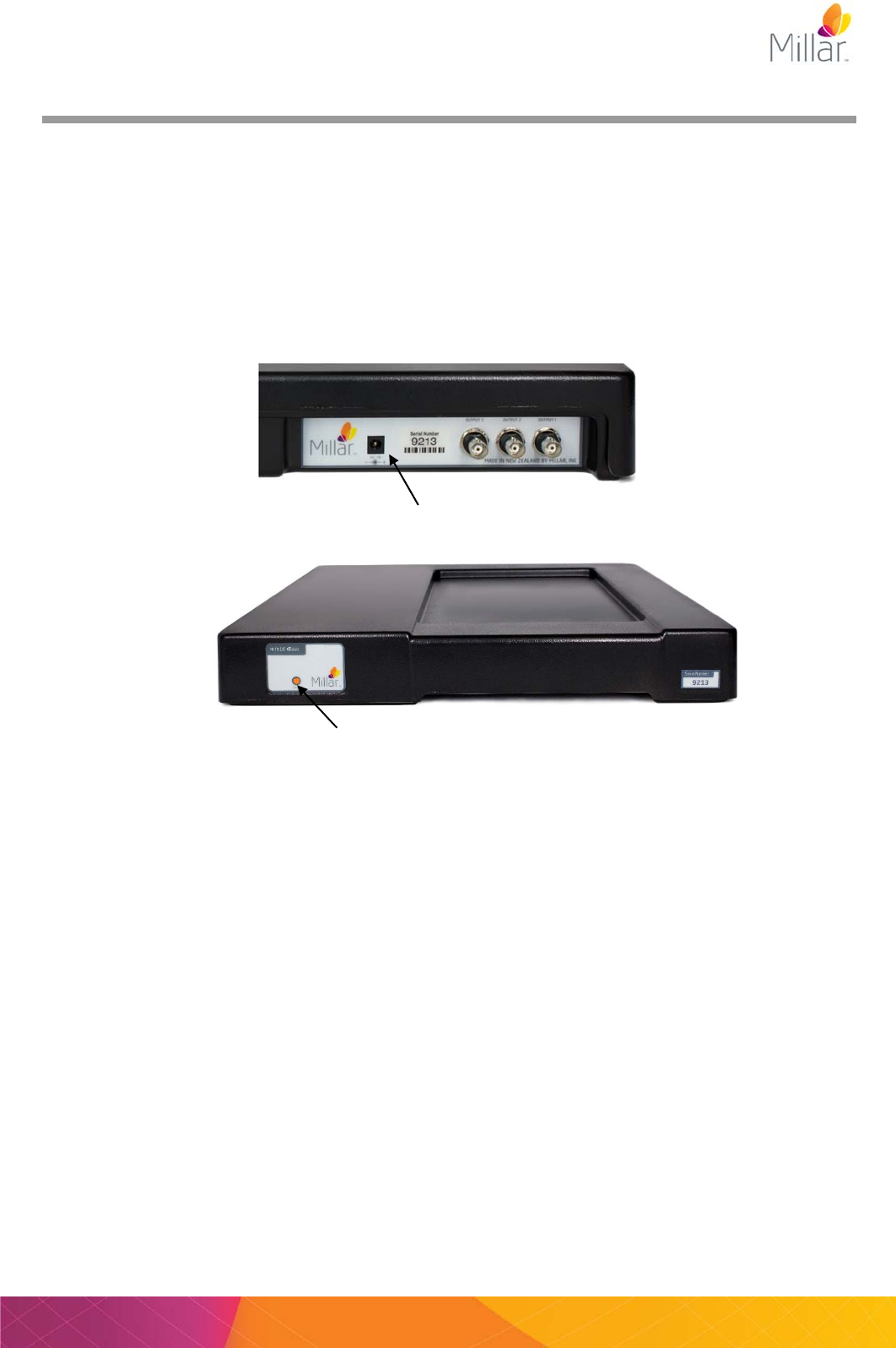
tBase Front
tBase Rear
When initially setting up a laboratory with multiple tBases, it is important that only ONE tBase is
turned on at a time. The tBases and telemeters are all shipped set to Channel “Setup”. Before
using the telemetry system each tBase and mouse telemeter needs to be configured and paired to
one of the 40 transmission Channels. It is important that only one tBase and one telemeter are
used on any particular channel to prevent signal interference.
The recommended arrangement of multiple tBases in a laboratory is detailed below. In particular,
note the distances from other tBases and metal objects.
Power socket Analog Outputs
Indent for cage positioning
Status light Air vent inlet
Air vent outlet
Serial number
Page 14 User Manual for Millar Mouse Telemetry MKT0006/A
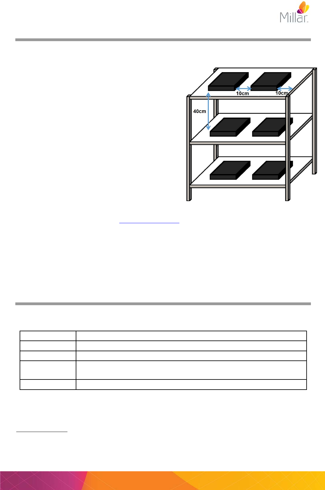
tBase Laboratory Setup
The tBase provides power to the telemeter using an electromagnetic field generated above and
below the tBase. For this reason, it is important that a tBase is NOT placed on a metal surface or
above or below other tBases (unless 40 cm apart). We
recommend the use of plastic shelving for your tBases.
Multiple tBases should be arranged so that there is
more than 10 cm horizontal and 40 cm vertical
separation between them. If using shelving that has
metal supports or framing then the tBases must be
>10cm away from these as well (don’t forgot to check
the underside of the shelves for metal supports). There
should also be more than 10 cm separation between the
top of a metal cage lid and any tBase on a shelf above.
If metal shelves are used, the tBase needs to be raised
at least 10 cm from the shelf surface but still maintaining
a vertical separation of at least 40 cm between tBases.
If the tBase shows a solid red light, then the tBases
need to be further separated (vertically and horizontally)
and/or move them further away from metal brackets,
supports, cables or power packs. Reset the tBase by
disconnecting and reconnecting the power. If the
problem continues, please contact support@millar.com.
IMPORTANT:
Connect ONLY the supplied and labelled “TR181 or MT110” Power Supply to the power
socket at the rear of the MT110 tBase. Please note: Using any other Power Supply will
invalidate the warranty and may damage the tBase.
DO NOT obstruct the air vents at the front and rear of the MT110. Ensure that any power
cables and other items are kept clear of the air vents.
Status lights
The status light at the front of the tBase provides information on the communication status between
the tBase and the telemeter.
The status lights on the tBase may flicker between solid green and solid orange during normal
operation as the telemeter enters and leaves the power field with normal activity of the mouse i.e.
mouse climbing on and off large objects in the cage.
*Troubleshooting: When the status light is solid red, the power field of the tBase has been disabled
and the telemeter will not be powered. This means that there will be no data recorded from the
telemeter. Cause: may be due to the tBase being placed too close to a metal surface or to another
tBase. Move the tBase away from any metal and then reset by turning the power off and then on
Status light
MT110 tBase
Solid Green The tBase is communicating with a telemeter on the same Channel
Solid Orange The tBase is turned on but is not communicating with a telemeter
Solid Red* The tBase has detected an issue with the telemetry setup and has disabled
the powering. Please see troubleshooting below for more information.
Flashing Red The tBase is in diagnostic mode. No telemeter data will be output
Example tBase arrangement on plastic shelves
with metal framing.
User Manual for Millar Mouse Telemetry Systems MKT006/A Page 15
again. If the problem persists, record a diagnostic file in ConfigSoft while the tBase is showing a red
status light and contact support@millar.com.
Analog Outputs and Calibration Values
After pairing the tBase/telemeter Channels, the analog outputs of the tBase will correspond to the
following signal outputs:
Telemeter model
Output 1 Output 2 Output 3
MT10B
Activity Biopotential Data Received
Calibration values 0V = 0 RAU
3.84V = 10 RAU
2.048V = 0mV
4.096V = 2.5mV
~0V = no data received
~3.3V = data received
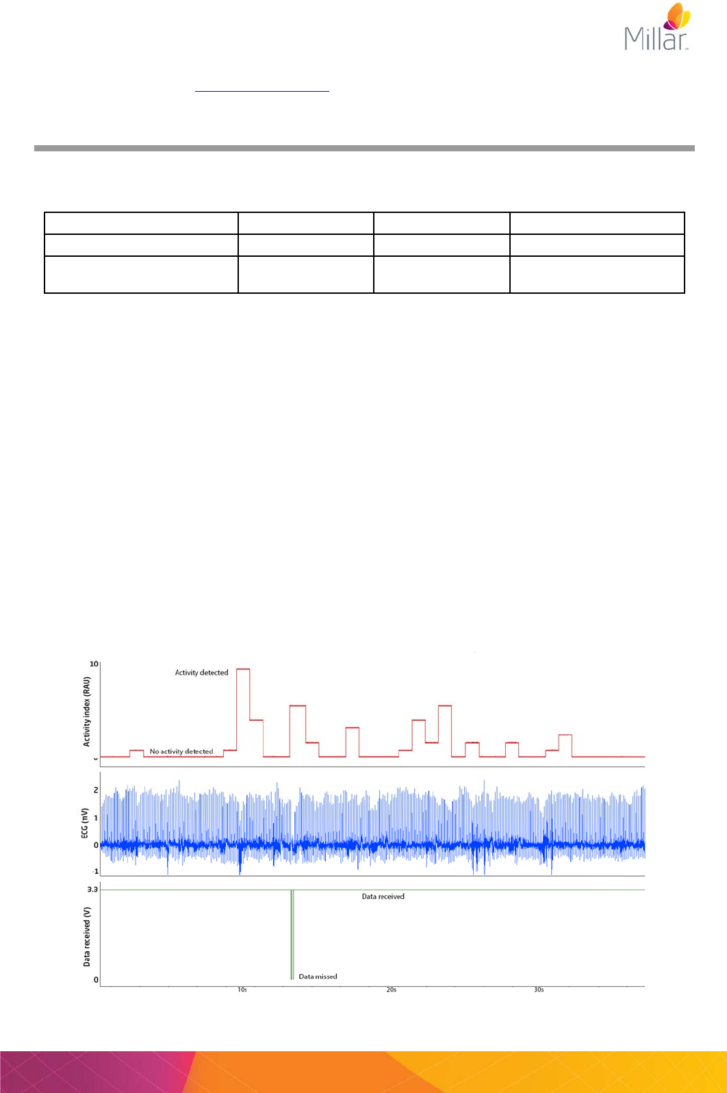
Activity: As the mouse moves in the power field the strength and orientation of the electromagnetic
field it receives changes. These changes are detected by the tBase and collated every ~1 second
to calculate an index of animal activity. The output is updated approximately every 1 second as
ranges from 0V – 3.84V in 13 levels (see picture below). We recommend converting the voltage
output to Relative Activity Units (RAU). The activity index can be used to determine relative changes
in activity between two time periods (e.g. night vs day).
Biopotential: This is your ECG, EEG or EMG signal. The potential difference between the two
electrode leads is measured by the telemeter (sampling rate 2 kHz) and transmitted to the tBase.
The tBase low-pass filters the signal at 1 kHz and reconstructs the analog signal.
Data Received: This provides an easy visual representation of when data is collected or when it
has been missed. When the tBase is receiving data from a telemeter, the Data Received analog
output will be ~3.3V. If no data is received from a telemeter for 12 milliseconds this output will drop
to ~0V until data is received again (see picture below). The most likely cause of data not being
received is that the mouse and telemeter have moved outside the inductive power field e.g. the
mouse is hanging off the bars of the cage lid and is more than 7cm above the tBase surface. The
Data Received output can be useful during data analysis to differentiate between real periods of low
signal amplitude and missing data e.g. skipped beats in ECG recordings.
Example recording showing the Activity Index, Biopotential and Data Received outputs.
Page 16 User Manual for Millar Mouse Telemetry MKT0006/A
The Mouse telemeter
Millar mouse telemeters are designed for single use and for 24/7 recordings from mice living in their
home cages. The telemeters are designed, with a unique contour, for use as subcutaneous implants
in mice >22 grams. Telemeters are shipped sterile and ready for implantation. ALL telemeters are
shipped on Channel “Setup” and each telemeter MUST be
configured to one of 40 different data recording Channels before
implantation. DO NOT change the Channel of the telemeter while
implanted in an animal. There is no need to unpack the telemeter
from the sterile packaging (see right) to change the channel.
The telemeters are precision electronic devices. Care must be taken not to damage the telemeter
body or electrodes as they cannot be repaired. Please read the section about Care and Handling
of your telemeters.
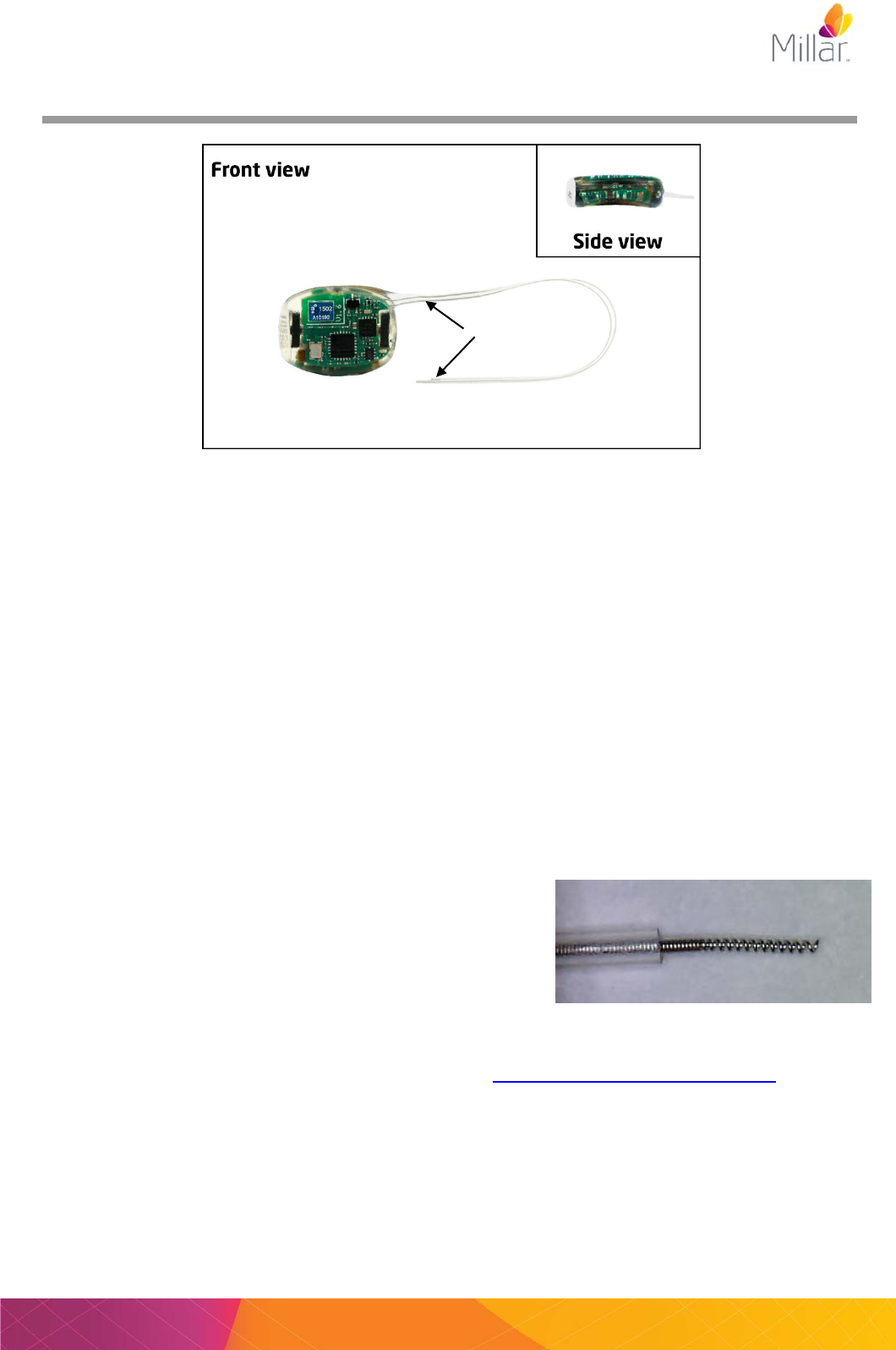
The MT10B telemeter (above) can measure a single biopotential signal between the positive and
negative leads for applications including ECG, EMG and EEG. For ease of identification, the
negative lead is trimmed shorter than the positive lead so the wire coil is flush with the tubing.
Before implanting a telemeter make sure to write down the serial number and Channel setting.
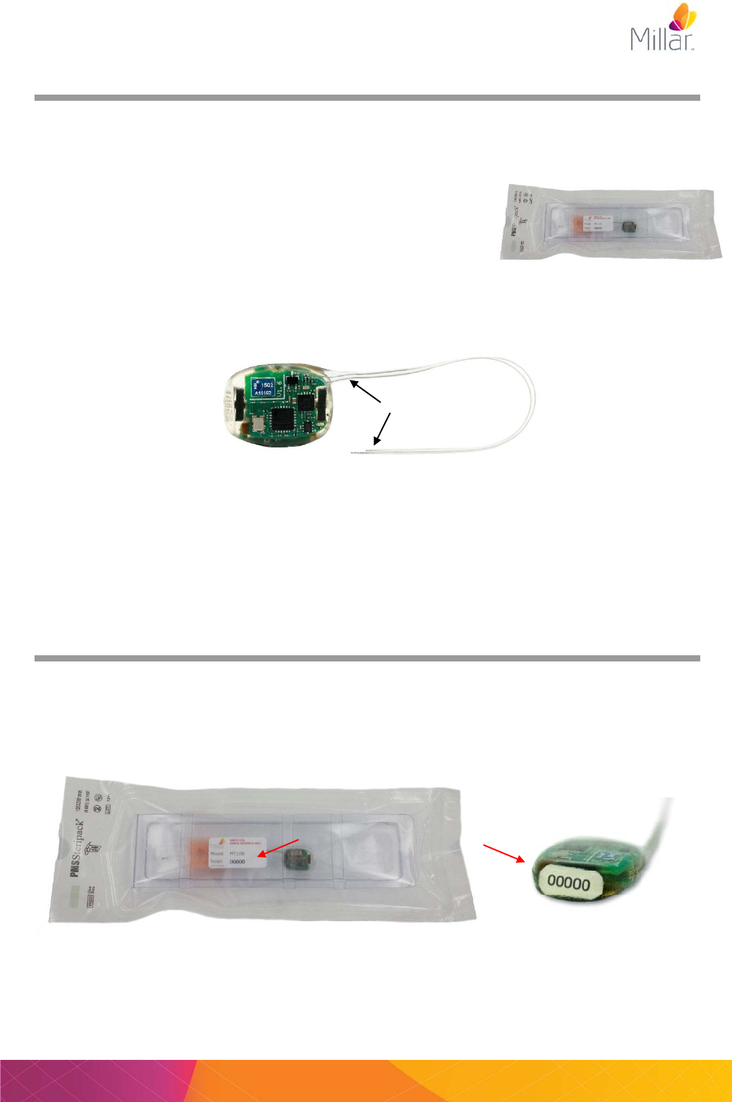
Channel and serial numbers
All telemeters are factory set to Channel “Setup” and need to be configured to different channels
before use (see page 18). The telemeter model and serial number can be found on the telemeter
packaging. In the example below, the model is MT10B, the serial number is 00000. The serial
number can also be found on the end of the telemeter.
Negative lead
User Manual for Millar Mouse Telemetry Systems MKT006/A Page 17
System setup and configuration
Before implanting a telemeter into an animal, the telemeter and the tBase to be used with the
telemeter must have their Channels paired. Please ensure that only one tBase and one telemeter
are being configured and paired at any one time. All tBases and telemeters are shipped on
Channel “Setup” and should be changed to one of the 40 available data collection Channels
before animal implantation. The tBase and telemeter need to be within 1 meter of the
Configurator during configuration.
1) Turn on the tBase (Status light should be orange). If this is the first time the tBase has been
turned on, it should be on the Channel “Setup”. If not, use the Configurator System to configure
the tBase Channel to “Setup” (see page 20 for details).
2) Place a telemeter (in its sterile packaging) in the center of the indent of the tBase. The tBase
will automatically start powering the telemeter as both the tBase and telemeter will be on
Channel “Setup”. The tBase status should turn green.
3) Using the Configurator system, first change the Channel of the mouse telemeter to one of the
40 data collection Channels (detailed instructions in the next two sections). The tBase status
light should now be orange. Remove the mouse telemeter from the tBase.
4) Configure the tBase to the same data collection Channel as the mouse telemeter using
ConfigSoft (detailed instructions in the next two sections). Place the telemeter on the tBase,
the status light should be green. Your system is now paired and ready for use.
Insert power plug here
Status light
Page 18 User Manual for Millar Mouse Telemetry MKT0006/A
Changing telemeter Channel
1) Place the mouse telemeter in the center of the indent of the tBase configured to the same
Channel (first use Channel = “Setup”). Ensure the telemeter and tBase are within 1 meter of
the Configurator. The tBase status light should be green to show the telemeter is powered and
communicating with the tBase.
2) Open ConfigSoft
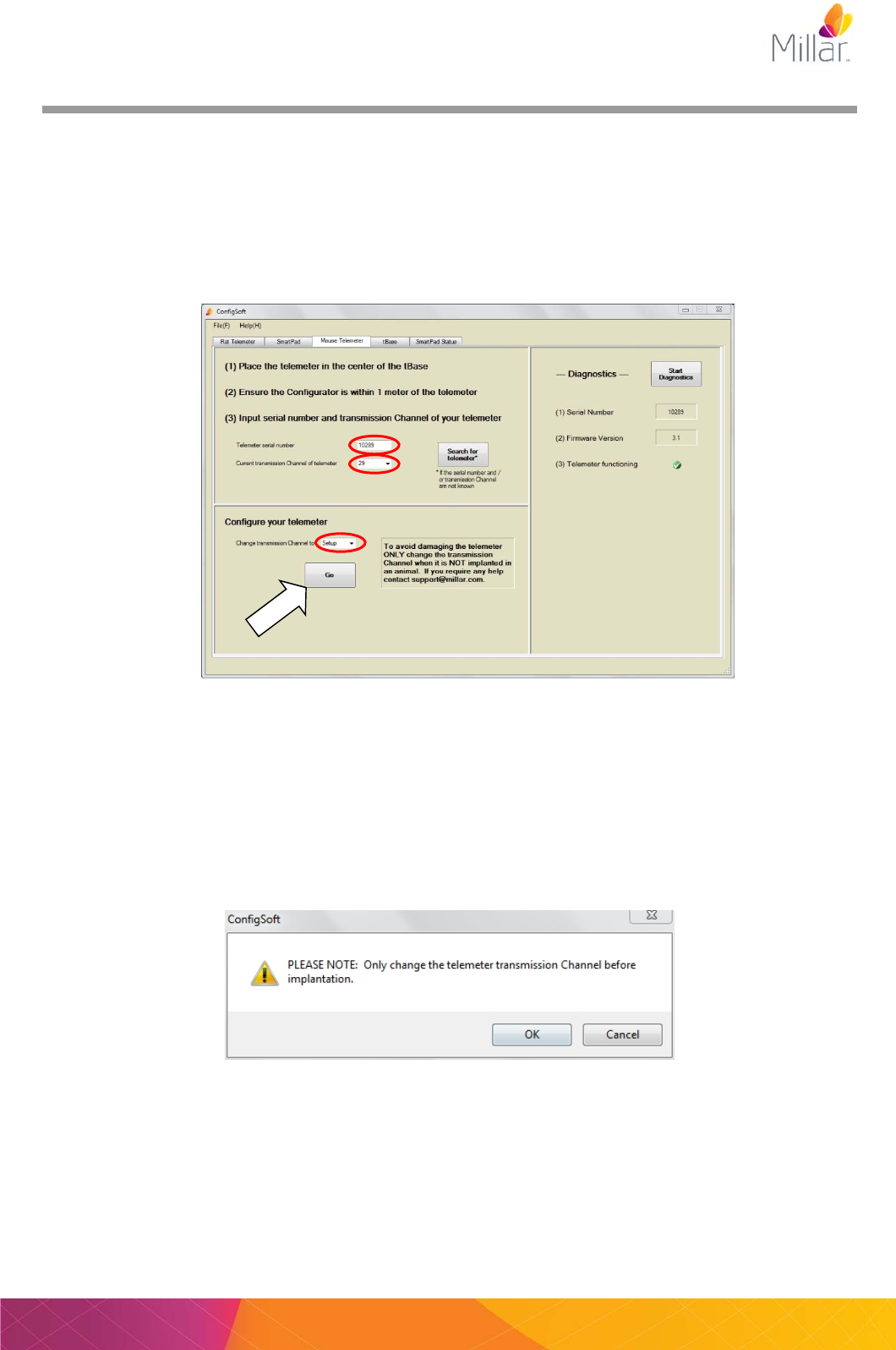
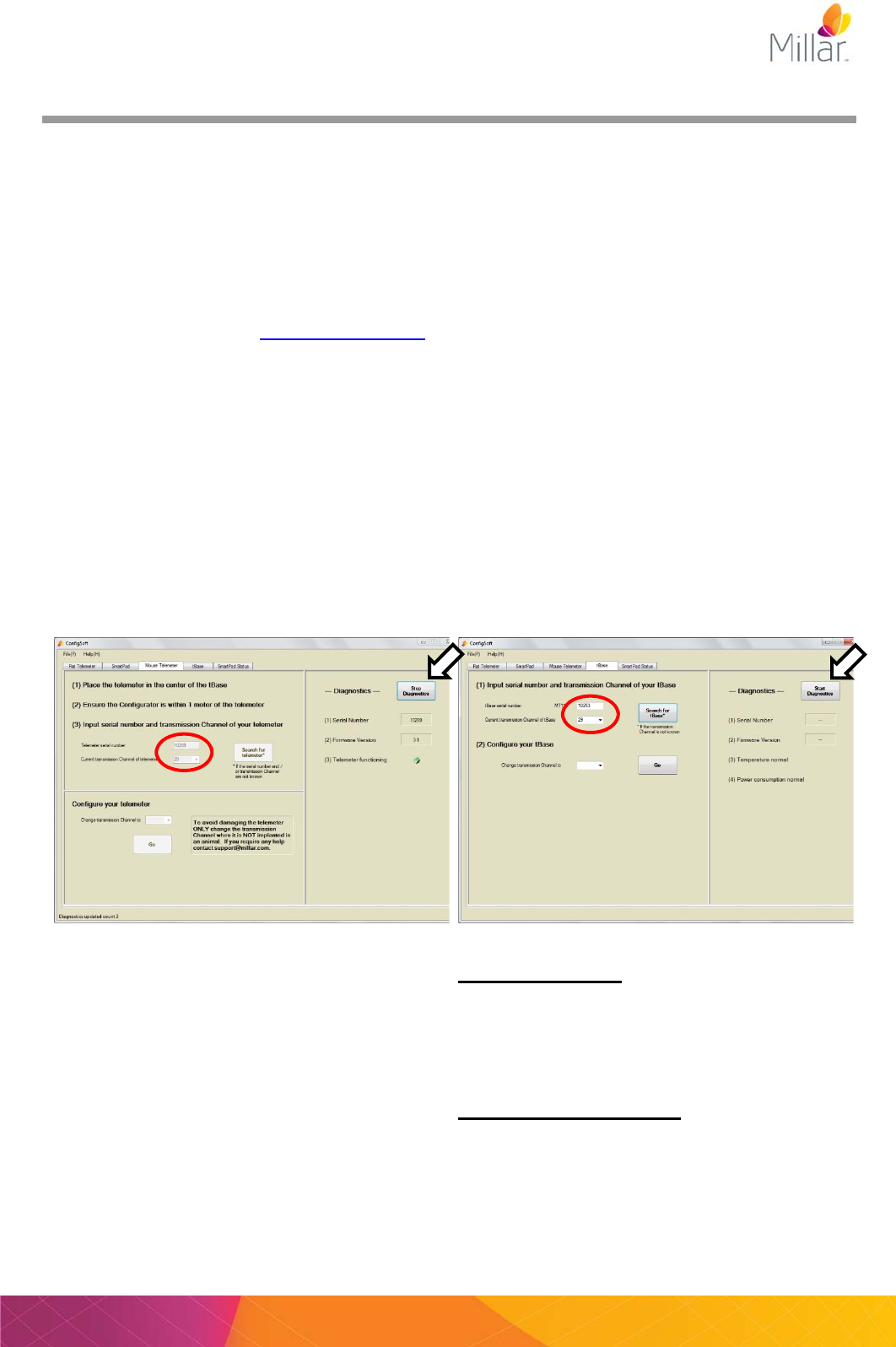
3) Click on the “Mouse Telemeter” tab
4) Enter the serial number of the telemeter. The number is on the outside of the telemeter
packaging or on the label at the end of the telemeter
.
5) Select or enter the current Channel number of the telemeter (first use: Channel = “Setup”).
6) To change the Channel number, select or enter the new Channel number in the “Configure your
telemeter” section.
7) Click Go to activate the new Channel.
8) A dialog will pop up with “Only change the telemeter transmission Channel before implantation”.
Click OK to confirm the choice.
User Manual for Millar Mouse Telemetry Systems MKT006/A Page 19
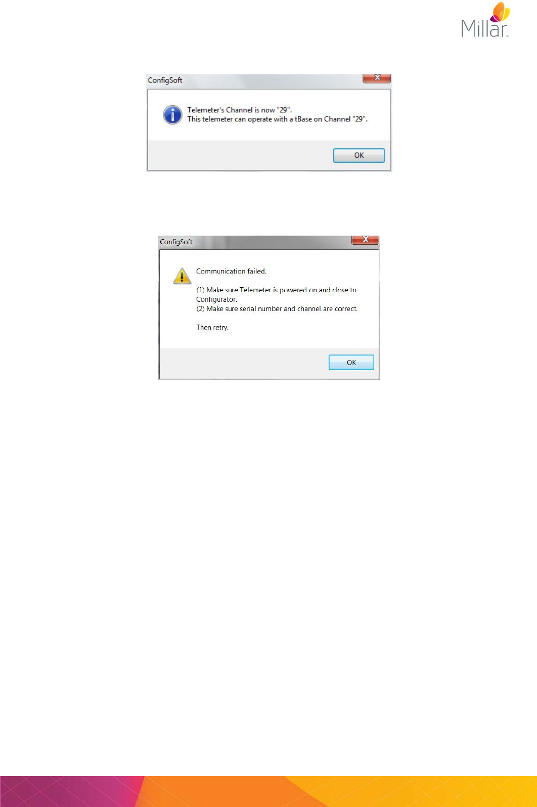
9) A message confirming the new telemeter Channel should appear. To make it easier for the
future, record the telemeter Serial number and Channel number for all telemeter configurations.
Troubleshooting: Configurator – ConfigSoft - telemeter
If the Configurator cannot communicate with the telemeter an error message may appear.
Solution:
Do the following and try again:
Check that you have entered the correct telemeter Serial number
Check that you have entered the correct telemeter Channel number
Make sure that the telemeter is on a tBase set to the same Channel
Move the telemeter and paired tBase closer to the Configurator
Check you only have one tBase/telemeter set to the same Channel
Move the telemeter to a different position on the tBase
Page 20 User Manual for Millar Mouse Telemetry MKT0006/A
Changing tBase Channel
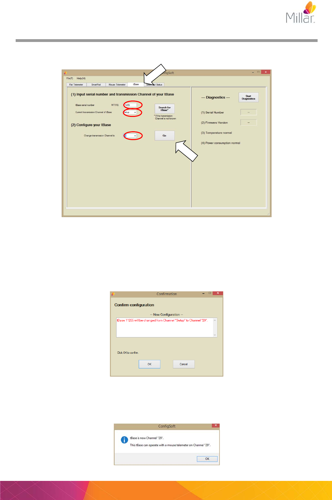
1) To change the tBase Channel and pair this with a telemeter, click on the “tBase” tab in
ConfigSoft.
2) Enter the serial number of the tBase (found on the front and rear of the tBase).
3) Enter current Channel number of the tBase (first use: Channel = “Setup”).
4) Under “Configure your tBase”, enter or select a new Channel number for the tBase (this should
be same as telemeter being used).
5) Click Go to activate the new Channel.
6) Click OK to confirm your choice.
6. The tBase status light will flash red for a few seconds before a message confirming that
the tBase channel has been changed appears. Record the tBase serial number and new
Channel number for future reference.
User Manual for Millar Mouse Telemetry Systems MKT006/A Page 21
7) If a telemeter on the same Channel is placed on the tBase, the Status light should change to
green. The telemeter and tBase are now on the same Channel, paired, and able to
communicate for data collection and transmission.
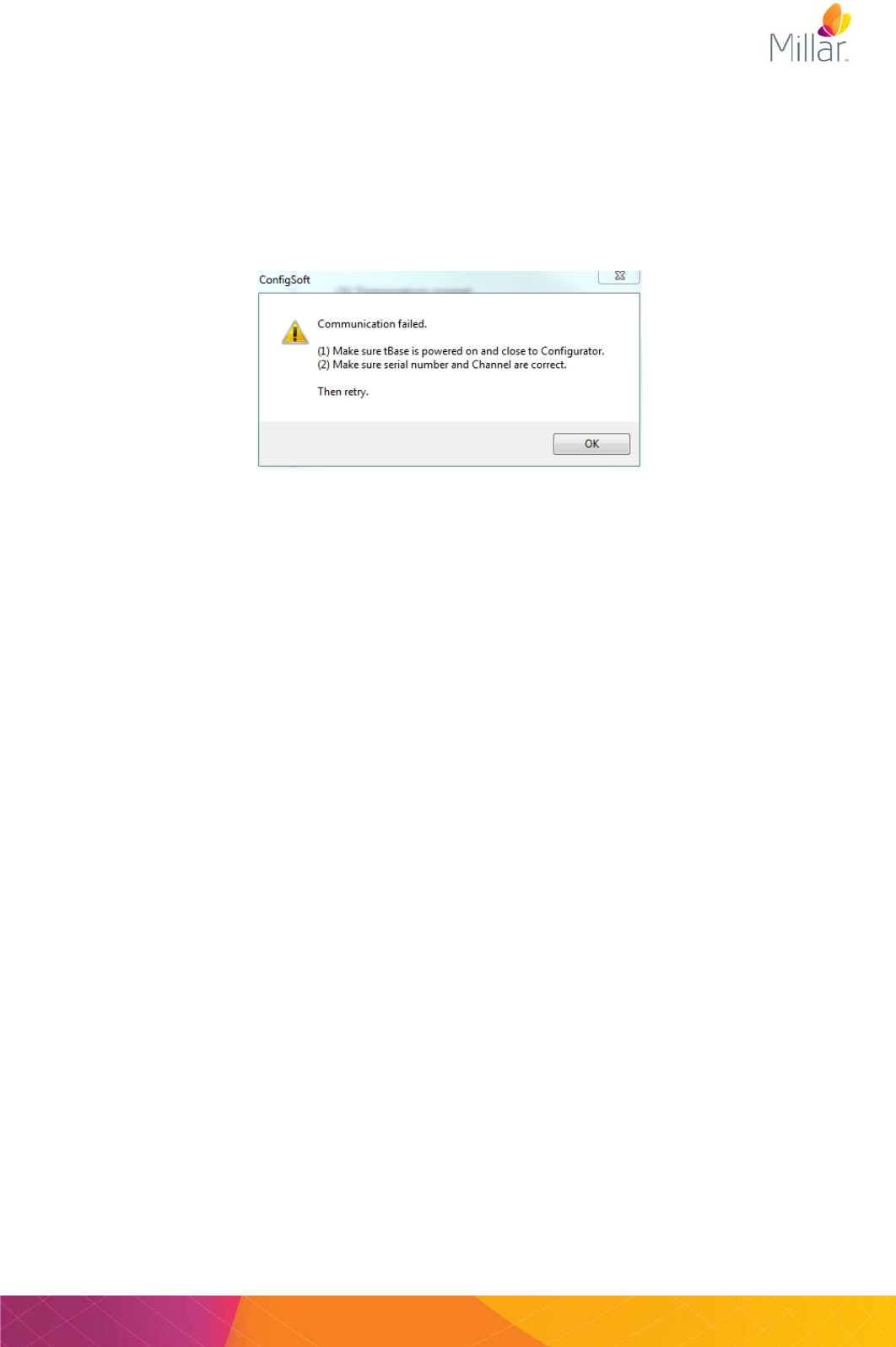
Troubleshooting: Configurator – ConfigSoft - tBase
If the Configurator cannot communicate with the tBase the following error message may appear.
Click OK and perform the following then retry:
Check that the light on the front of the tBase is orange.
Check that you entered the correct Serial and/or Channel numbers.
Move tBase closer to Configurator.
Check you only have one tBase set to the same Channel
Repeat the above process for each of the tBases and telemeters to configure each pair to a different
Channel.
Your Millar Mouse Telemetry System is now configured and ready for use.
Page 22 User Manual for Millar Mouse Telemetry MKT0006/A
Positioning the telemeter during surgery
The telemeter has a unique contoured shape with a curved convex front and a concave underside
for better positioning in the mouse. The telemeter body is designed to fit subcutaneously, with the
concave underside sitting against the flank of the mouse and the convex front side next to the skin.
Biopotential lead placement
MT10B Mouse biopotential telemeters are supplied with 8cm long stainless steel bipolar electrodes
suitable for measurement of biological electric potential signals including ECG, EEG and EMG. To
reduce noise in the recorded signal it is recommended that the electrode leads be trimmed to length
at the time of surgery rather than coiling any excess wire. It is important however to allow some
extra length in the electrode leads to allow for animal movement. For ease of identification, the
negative lead is trimmed shorter than the positive lead so the wire coil is flush with the tubing.
After trimming the electrode leads to the desired length, it will be necessary to expose the coiled
stainless steel electrode within the lead tubing. Care must be taken to avoid damaging the wire as
this can lead to wire breakages and poor signal quality during recordings. The recommended way
to expose the electrode wire is to use a surgical microscope and carefully trim the tubing from around
the wire. Do not trim, stretch or disturb the wire coil within 2.5 cm of the telemeter body.
The stainless steel electrodes are coiled for maximum
strength and flexibility. The coil can slip out of a suture
however so it may be useful to carefully stretch the coils at
the tip of the electrode to allow a suture thread to pass
between the coils.
It is not recommended that sutures be placed around the leads other than around the point of contact
with the tissue as this may provide a stress point on the leads and cause them to break. More
information and surgical videos are available online at http://millar.com/knowledge-center
Negative lead
User Manual for Millar Mouse Telemetry Systems MKT006/A Page 23
Telemeter Body Placement for Powering and Signal Maximization
The tBase provides an electromagnetic field to power the mouse telemeter. This field provides
effective powering of the telemeter within up to 7cm vertical distance from the bottom of the indent
on the tBase. However, when the telemeter body is more than 7cm above the tBase, the telemeter
will not be powered and data collection will not be available. This can occur when the mouse hangs
from the wire cage lid or is physically sitting more than 7cm above the tBase.
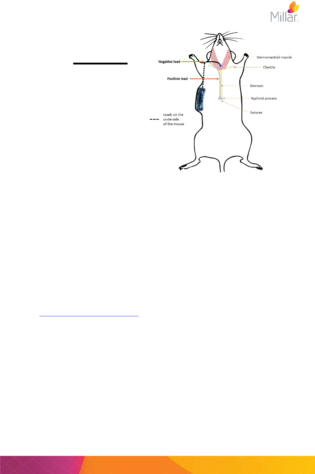
The recommended site for telemeter placement is on the flank/side of the animal between the front
and the rear limbs with the concave surface of the telemeter against the body. Placement on the
right hand side of the mouse means the electrode leads will exit from the top corner of the telemeter
body and can be tunneled over the shoulder for ECG placement or to the skull for measurement of
EEG.
Powering may not be as effective if the telemeter is placed on the back of the animal or up near the
shoulders as that creates additional distance from the tBase, especially when the animal is up on
their hind legs. More information and surgical videos are available online at the Millar Knowledge
Center (http://millar.com/knowledge-center).
It is also strongly recommended that bedding within the cage is kept to a minimum and tall items,
which the mouse can climb on top of, are removed. For example, large enrichment tubes, multi-
level mouse houses or other toys with elevated flat surfaces should be avoided.
Example
placement of
electrode leads
for recording of
high quality ECG

Page 24 User Manual for Millar Mouse Telemetry MKT0006/A
Telemeter Care and Handling
All telemeters are shipped pre-sterilized using ethylene oxide gas sterilization and can be
implanted without the need for further sterilization. Telemeters will remain sterile as long as
the pouch is intact and not compromised. It is recommended that they remain in their original
packaging until surgical implantation.
However, if the telemeters have been accidently removed from the sterile packaging prior to
implantation, or if they come in contact with non-sterile surfaces during surgery, they can be
sterilized using one of the methods below:
Chemical Sterilants
Glutaraldehyde may be used to sterilize the telemeters. Glutaraldehyde (Fisher Scientific) must be
diluted to 2% before use. Check your local chemical supply company for availability. Do not use
gluteraldehyde solutions containing surfactants (i.e. do not use Cidex 7, Cidex Plus 28 Day or
Metrocide 28). Suitable products are in the table below:
Rinse with Sterile Saline
Telemeters sterilized with a chemical sterilant should always be washed thoroughly in sterile saline
before implantation to remove all traces of the sterilant.
Ethylene Oxide Gas Sterilization
Telemeters are suitable for Ethylene Oxide sterilization as long as they are not subjected to
temperatures above 60°C.
*Important note:
Under no circumstances should the telemeter be autoclaved or subjected to temperatures over 60°C
as this will damage the telemeter.
Do not sterilize by radiation (gamma or e-beam), plasma, alcohol, peroxide or formaldehyde vapor
solutions. This will damage the telemeter.
Customers are liable for product replacement if recommended products and instructions are not
used or followed. If there are any questions about a chemical or procedure please contact Millar
(support@millar.com).
Warning: Some examples of chemicals that will cause damage to telemeters include, but are
not limited to: alcohols, phenols, iodophors, and hypochlorite. Please confirm with Millar
before using any product other than the approved products list above.
** Products with similar names are available but may not be suitable. Please use only products
specified or contact Millar for clarification (support@millar.com).
Removal
The mouse telemeters are designed as a single use product. Depending on your biohazard or
medical waste disposal services, it is possible to discard the biopotential leads and/or the telemeter
body while still implanted in the mouse at the end of the experimental protocol.
Trade Name Manufacturer Active Ingredient Soak Time / Temperature
Cidex Activated
Dialdehyde
Solution
Advanced Sterilization
Products (J&J)
Gluteraldehyde 1-2 hours / 25°C (77°F)
Cidex OPA Advanced Sterilization
Products (J&J)
Orthopthalaldehyde 16-30 mins / 20°C (68°F)
MetriCide Metrex Gluteraldehyde 1-2 hours / 25°C (77°F)
User Manual for Millar Mouse Telemetry Systems MKT006/A Page 25
Diagnostics
Using the Configurator System the user can view and change the Channel of the telemeter. The
“Search for telemeter” function can be used to find the serial number of an implanted telemeter if
this was not recorded prior to implantation.
The “Search for tBase” function will find the Channel of a specific tBase. The Configurator System
can also be used to investigate the status of the temperature and power consumption of the tBase.
Diagnostics files
When sending emails to support@millar.com for troubleshooting, you may be asked to send a
diagnostics file. To run diagnostics for the mouse telemeter or tBase, enter the Serial number and
the Channel number in the “mouse telemeter” or “tBase” dialog, press the “Start Diagnostics” button
and choose to save the file. ConfigSoft will ask you to confirm the name and location for the log file.
The default filename includes the telemeter or tBase serial number and the date and time the
diagnostics was started (see example below). The log file and display are both updated every 1 s.
A count of the updates is shown in the bottom left hand corner of the window. Diagnostics will
continue to run until you press “Stop Diagnostics”. The log file is then automatically saved. If you
choose to save a log file you will not be able to stop the diagnostics for at least 2 minutes.
Please note that you cannot record data from your telemeter using a tBase that is in Diagnostics
mode (the status light flashes red and a saw tooth pattern will output from the tBase analog outputs).
Mouse telemeter diagnostics tBase diagnostics
MTx10289_log_2015_6_9_16_11.txt Tb10253_log_2015_6_9_16_48.txt
Temperature normal
= the temperature of the tBase is at acceptable
levels.
= the temperature is above acceptable limits.
Please contact Millar (support@millar.com).
Power consumption normal
= tBase power consumption is normal.
= Excess power consumption has been detected.
The Status light on the front of tBase will be red.
The tBase may be too close to a metal surface
or another tBase.

Page 26 User Manual for Millar Mouse Telemetry MKT0006/A
tBase Technical Specifications
tBase MT110
tBase functions
Provides power only to mouse telemeters using inductive wireless
charging, outputs standard analog voltage compatible with any
data acquisition system (BNC), has a built-in fan for optimal
temperature operation.
Weight
3.0 Kg
Dimensions
400(w) x 450(d) x 65(h) mm / 15.7(w) x 17.7(d) x 2.6(h) in
Cage platform dimensions
190(w) x 335(d) mm / 7.5(w) x 13.2(d) in
Power input
100-240 V, 50-60 Hz
Max Power draw
90W
Temperature Operating Range
10 to 40 degrees Celsius
Output Connectors
BNC x 3
Output Voltage Range
0 to 4V
Low Pass filtering on signal outputs
Cut off frequency = 1000 Hz

User Manual for Millar Mouse Telemetry Systems MKT006/A Page 27
Telemeter Technical Specifications
The technical specifications in the table below are for the mouse telemeters.
Biopotential Input range +2.5 mV
Biopotential Resolution 12 bit A/D
Biopotential High pass characteristics AC coupled, single pole, -3dB point at 2 Hz
Biopotential Low pass characteristics AC coupled, single pole, -3dB point at 440 Hz
Biopotential Electrode leads 8cm length, coiled stainless steel
Biopotential Electrode diameter 0.42 mm
Temperature operating range 34 to 41 degrees Celsius
Sampling frequency 2000 Hz
Low Pass filtering by tBase Cut off frequency = 1000 Hz
Transmitted signal Fully digital at 2.4 GHz
Channels 40 transmission frequencies are available, user set
Minimum animal weight 22 grams
Outer material Epoxy (telemeter body) and polyurethane (leadset)
Volume 1.6 cc
On-off mechanism Powered when placed on the tBase and deactivated when
removed from the tBase.
Calibration No user intervention required (calibration values stored within
each telemeter).
Analog output calibration values
Activity: 0V output = 0 RAU
3.84V output = 10 RAU
Biopotential: 2.048V output = 0mV input,
4.096V output = 2.5 mV input
Data received: ~0V output = 0 (no data received),
~3.3V = 1 (data received)

Page 28 User Manual for Millar Mouse Telemetry MKT0006/A
Frequently Asked Questions........
Would the animal be harmed by staying in the tBase powering field?
There are no known biological effects of the inductive field. Studies have shown that field strengths
much higher than generated by the Millar tBase have no effect. The level of magnetic field is quite
low and remains useable only ~7 cm above the tBase.
How many animals can be monitored at one time?
Each telemeter sends its signal on one of 40 unique transmission Channels. Therefore up to 40
telemeters and animals can be monitored at one time (on separate tBases).
Can I use the Millar Mouse Telemetry System alongside the Millar Rat Telemetry System?
Both the Millar Rat Telemetry System and Millar Mouse Telemetry System can be operated on any
of the 40 independent data collection Channels with minimal interference between animals.
Therefore, both systems can be operated side-by-side to monitor up to a total of 40 rats or mice, or
a combination of both rats and mice, at any one time. Your existing rat Configurator system may
require a firmware or software update before use with mouse telemeters (please contact Millar).
Is there any interference between mouse telemeters?
No. As long as each telemeter is set to use a different Channel they use separate transmission
frequencies. No shielding is required between cages. Close proximity is possible.
Do I need to use special mouse cages with the tBase?
Special caging is not required for use with this system. The only limitation is that the cage base
must sit on the surface of the tBase indent. The indent of the tBase for the mouse cage is 190mm
x 335mm and is compatible with any non-metallic cage bottom which fits these dimensions.
Contact Information
US Head Office
Houston, Texas
Toll free (in USA) 1 800 669 2343
TEL: +1 832 667 7000
FAX: +1 713 714 8497
New Zealand Office
Auckland, New Zealand
TEL: +64 9 367 7126
FAX: +64 9 367 7157
EMAIL support@millar.com or sales@millar.com
WEB www.millar.com
Further questions?
Millar is proud to offer unlimited technical support and advice to all its customers. Register on our
free online Knowledge Center (http://millar.com/knowledge-center) for surgical recommendations
and hardware troubleshooting advice. If you have any further questions, our team of engineers
and physiologists can advise on specific applications and equipment configurations. Please
contact us.