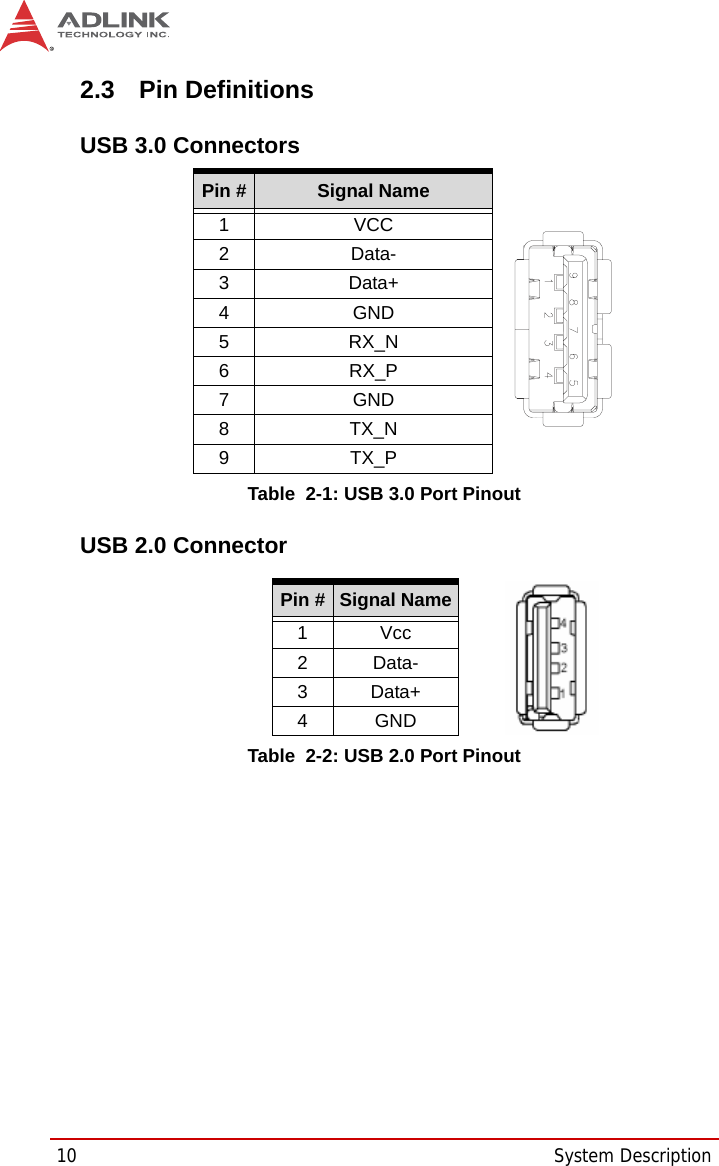
ADLINK TECHNOLOGY STC-1505 Smart Touch Computer User Manual STC 1005 1205 1505 Smart Touch Computer
ADLINK TECHNOLOGY INC. Smart Touch Computer STC 1005 1205 1505 Smart Touch Computer
UserManual.wiki
>
ADLINK TECHNOLOGY
>
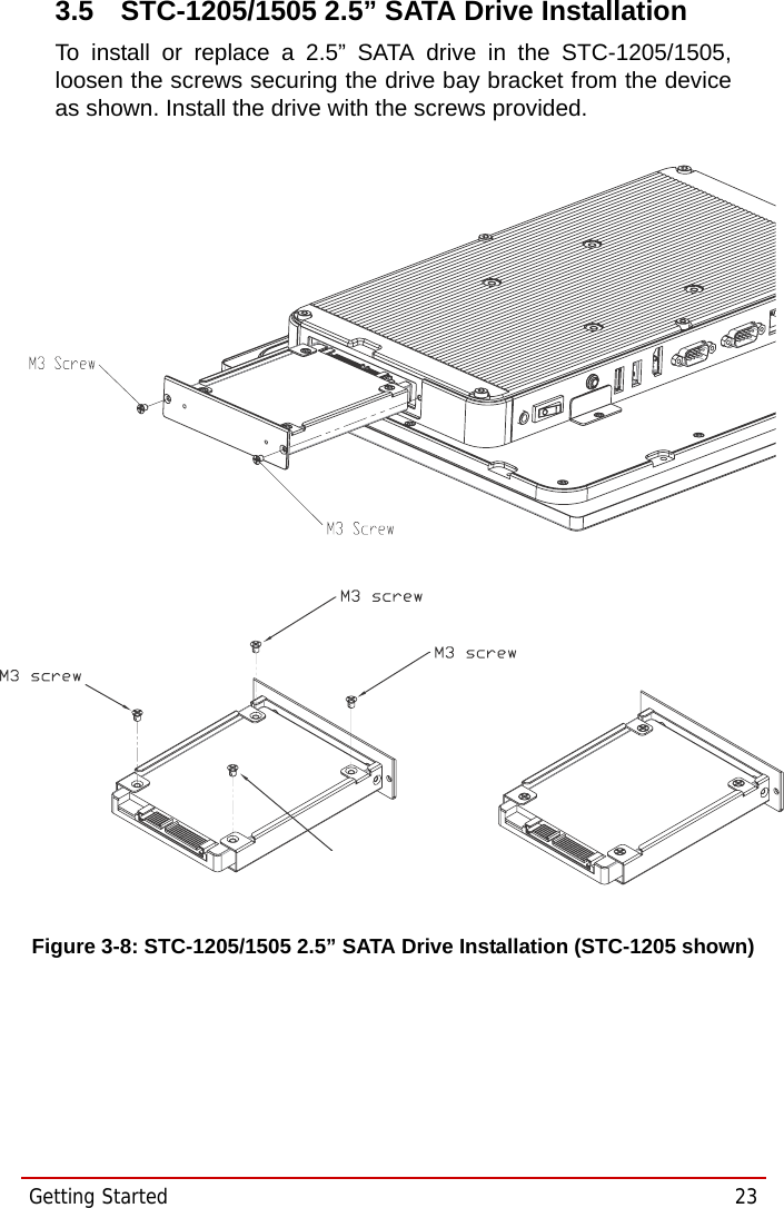
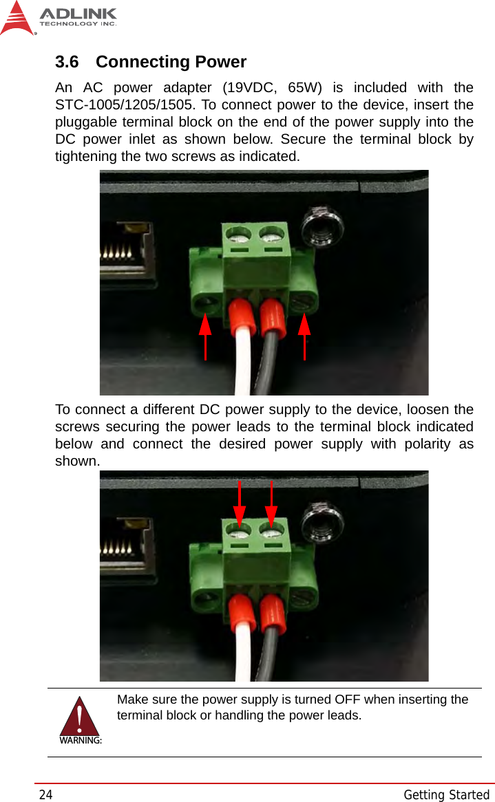
STC 1505 User Manual
User Manual
Navigation menu
Upload a User Manual
Namespaces
Wiki Guide
HTML
PDF
Info
Views
User Manual
Discussion / Help
Navigation