ADLINK TECHNOLOGY STC-1505 Smart Touch Computer User Manual STC 1005 1205 1505 Smart Touch Computer
ADLINK TECHNOLOGY INC. Smart Touch Computer STC 1005 1205 1505 Smart Touch Computer
User Manual

Advance Technologies; Automate the World.
Manual Rev.: 0.30
Revision Date: October 5, 2015
Part No: 50-1Z203-2000
67&
Smart Touch Computer
User’s Manual

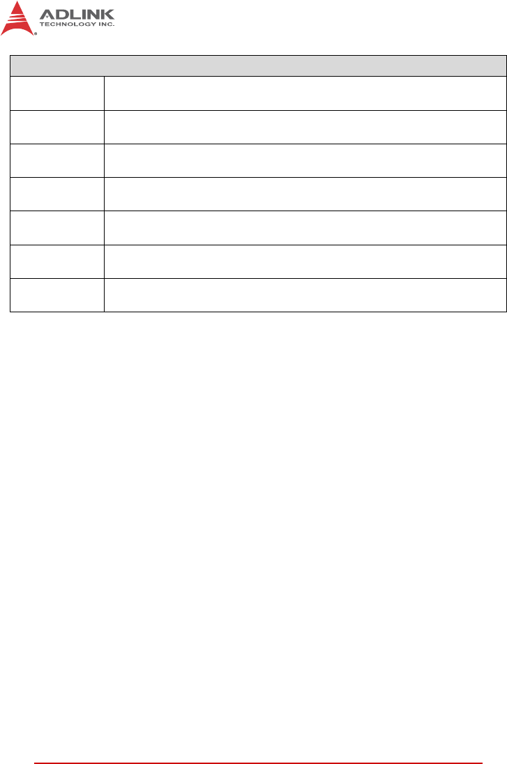
ii Revision History
Revision History
Revision Release Date Description of Change(s)
0.10 17/07/2015 Preliminary release
0.20 11/08/2015
Update COM1/2 specification; add OS support;
panel mount thickness support; power switch
description
0.30 05/10/2015 Add FCC statement

Preface iii
STC-105
Preface
Copyright 2015 ADLINK Technology Inc.
This document contains proprietary information protected by copy-
right. All rights are reserved. No part of this manual may be repro-
duced by any mechanical, electronic, or other means in any form
without prior written permission of the manufacturer.
Disclaimer
The information in this document is subject to change without prior
notice in order to improve reliability, design, and function and does
not represent a commitment on the part of the manufacturer.
In no event will the manufacturer be liable for direct, indirect, spe-
cial, incidental, or consequential damages arising out of the use or
inability to use the product or documentation, even if advised of
the possibility of such damages.
Environmental Responsibility
ADLINK is committed to fulfill its social responsibility to global
environmental preservation through compliance with the Euro-
pean Union's Restriction of Hazardous Substances (RoHS) direc-
tive and Waste Electrical and Electronic Equipment (WEEE)
directive. Environmental protection is a top priority for ADLINK.
We have enforced measures to ensure that our products, manu-
facturing processes, components, and raw materials have as little
impact on the environment as possible. When products are at their
end of life, our customers are encouraged to dispose of them in
accordance with the product disposal and/or recovery programs
prescribed by their nation or company.
Trademarks
Product names mentioned herein are used for identification pur-
poses only and may be trademarks and/or registered trademarks
of their respective companies.
iv Preface
Conventions
Take note of the following conventions used throughout this
manual to make sure that users perform certain tasks and
instructions properly.
NOTE:
NOTE:
Additional information, aids, and tips that help users perform
tasks.
CAUTION:
Information to prevent minor physical injury, component dam-
age, data loss, and/or program corruption when trying to com-
plete a task.
WARNING:
Information to prevent serious physical injury, component
damage, data loss, and/or program corruption when trying to
complete a specific task.

Preface v
STC-1005/1205/1505
Federal Communication Commission Interference Statement
This equipment has been tested and found to comply with the lim-
its for a Class B digital device, pursuant to Part 15 of the FCC
Rules. These limits are designed to provide reasonable protection
against harmful interference in a residential installation. This
equipment generates, uses and can radiate radio frequency
energy and, if not installed and used in accordance with the
instructions, may cause harmful interference to radio communica-
tions. However, there is no guarantee that interference will not
occur in a particular installation. If this equipment does cause
harmful interference to radio or television reception, which can be
determined by turning the equipment off and on, the user is
encouraged to try to correct the interference by one of the follow-
ing measures:
XReorient or relocate the receiving antenna.
XIncrease the separation between the equipment and
receiver.
XConnect the equipment into an outlet on a circuit different
from that to which the receiver is connected.
XConsult the dealer or an experienced radio/TV technician
for help.
This device complies with Part 15 of the FCC rules. Operation is
subject to the following two conditions: (1) this device may not
cause harmful interference, and (2) this device must accept any
interference received, including interference that may cause unde-
sired operation.
This device and its antenna(s) must not be co-located or operating
in conjunction with any other antenna or transmitter.
Any changes or modifications not expressly approved by the party
responsible for compliance could void the user's authority to oper-
ate this equipment.
NOTE:
NOTE:
FCC Radiation Exposure Statement
This equipment complies with FCC radiation exposure limits
set forth for an uncontrolled environment. This equipment
should be installed and operated with minimum distance 20cm
between the radiator and your body.

vi Preface
This page intentionally left blank.

Table of Contents vii
STC-1005/1205/1505
Table of Contents
Revision History...................................................................... ii
Preface.................................................................................... iii
List of Figures ........................................................................ ix
List of Tables.......................................................................... xi
1 Introduction ........................................................................ 1
1.1 Overview.............................................................................. 1
1.2 Features............................................................................... 1
1.3 Package Contents ............................................................... 2
1.4 Mechanical Dimensions....................................................... 3
2 System Description............................................................ 7
2.1 Specifications....................................................................... 7
2.2 I/O Panel Layout .................................................................. 9
2.3 Pin Definitions.................................................................... 10
3 Getting Started ................................................................. 15
3.1 Panel Mounting.................................................................. 15
3.2 SD Card Installation........................................................... 20
3.3 STC-1005 SATA Slim Drive Installation ............................ 21
3.4 STC-1205/1505 SATA Slim Drive Installation ................... 22
3.5 STC-1205/1505 2.5” SATA Drive Installation .................... 23
3.6 Connecting Power ............................................................. 24
Important Safety Instructions.............................................. 27
Getting Service...................................................................... 29

viii Table of Contents
This page intentionally left blank.

List of Figures ix
STC-1005/1205/1505
List of Figures
Figure 1-1: STC-1005 Dimensions..................................................... 3
Figure 1-2: STC-1205 Dimensions..................................................... 4
Figure 1-3: STC-1505 Dimensions..................................................... 5
Figure 2-1: STC-1005/1205/1505 Rear I/O Layout............................ 9
Figure 3-1: Panel Mount Installation ................................................ 16
Figure 3-2: STC-1005 Panel Mount Cutout Dimensions.................. 17
Figure 3-3: STC-1205 Panel Mount Cutout Dimensions.................. 18
Figure 3-4: STC-1505 Panel Mount Cutout Dimensions.................. 19
Figure 3-5: SD Card Installation (STC-1005 shown)........................ 20
Figure 3-6: STC-1005 SATA Slim Drive Installation ........................ 21
Figure 3-7: STC-1205/1505 SATA Slim Drive Installation ............... 22
Figure 3-8: STC-1205/1505 2.5” SATA Drive Installation ................ 23

xList of Figures
This page intentionally left blank.

List of Tables xi
STC-1005/1205/1505
List of Tables
Table 2-1: USB 3.0 Port Pinout....................................................... 10
Table 2-2: USB 2.0 Port Pinout....................................................... 10
Table 2-3: HDMI Port Pinout........................................................... 11
Table 2-4: COM1/2 Port Pinouts..................................................... 11
Table 2-5: RJ-45 GbE Pin Definitions............................................. 12
Table 2-6: LAN LED Status Definitions........................................... 12
Table 2-7: DC Power Input Pinout .................................................. 13

xii List of Tables
This page intentionally left blank.

Introduction 1
STC-1005/1205/1505
1 Introduction
1.1 Overview
The STC-1005/1205/1505 series of Smart Touch Computers is
designed for industrial automation and other applications in harsh
environments requiring an IP65 compliant front bezel with pro-
jected capacitive multi-touch display. Typical applications include
industrial control systems for the food and beverage industries;
automated buildings; transportation; hospitals; factories; and lei-
sure facilities.
1.2 Features
X10.4”/12.1”/15” 4:3 TFT-LCD display
X1024 x 768 resolution
X5-wire resistive touch sensor and optional projected capaci-
tive sensor
X400/500 nits (w/o touch screen attached)
XIntel® Atom™ Processor E3845, quad core, 1.91GHz
X2GB DDR3L soldered onboard
X1x USB 2.0, 2x GbE, 2x RS-232, 1x HDMI Port
XExternally accessible SD card slot & SATA drive bay
XSupports VESA and panel mounting
XIP65 rated front panel
X9-24V DC power input

2Introduction
1.3 Package Contents
Please check that your package contains the items below. If you
discover damaged or missing items, please contact your vendor.
XSTC-1005/1205/1505 Smart Touch Computer
X19 VDC power adapter (input: 100-240 VAC, 1.5A, 50-60Hz)
XPanel mount bracket kit
XSATA drive mounting screws
WARNING:
DO NOT install or apply power to equipment that is damaged
or if there is missing/incomplete equipment. Retain the ship-
ping carton and packing materials for inspection. Please con-
tact your ADLINK dealer/vendor immediately for assistance.
Obtain authorization from your dealer before returning any
product to ADLINK.
Introduction 3
STC-1005/1205/1505
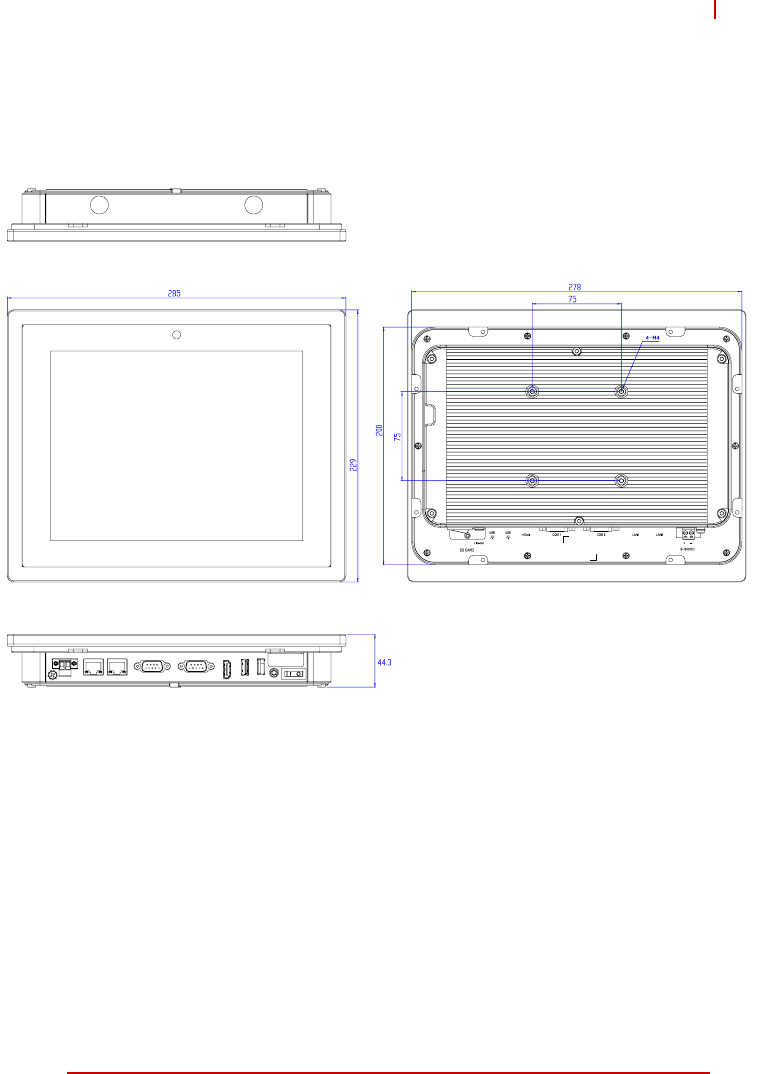
1.4 Mechanical Dimensions
Figure 1-1: STC-1005 Dimensions
Dimensions in mm
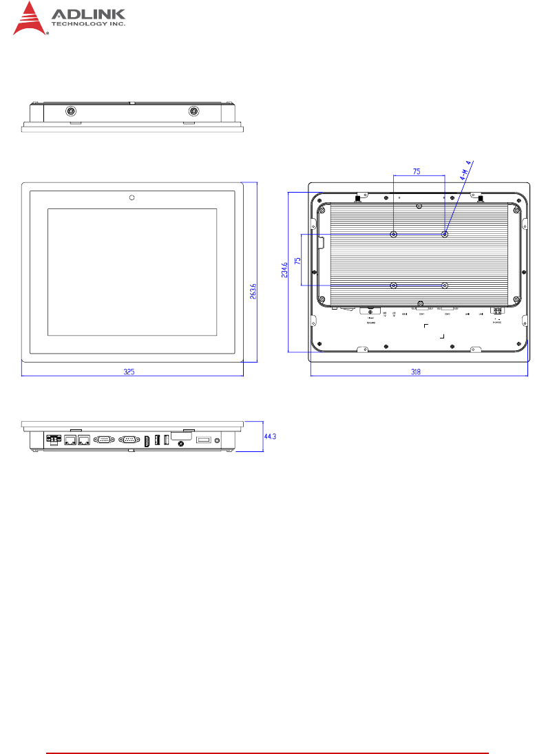
4Introduction
Figure 1-2: STC-1205 Dimensions
Dimensions in mm
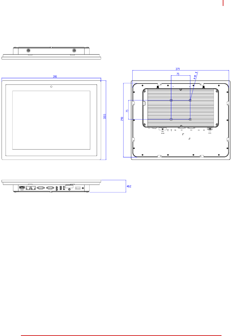
Introduction 5
STC-1005/1205/1505
Figure 1-3: STC-1505 Dimensions
Dimensions in mm

6Introduction
This page intentionally left blank.

System Description 7
STC-1005/1205/1505
2 System Description
2.1 Specifications
Display
Display Size 10.4" 12.1" 15"
Resolution 1024x 768 pixels
Brightness 500 nits (w/o touch) 400 nits (w/o touch)
Contrast
Ratio 1000:1 700:1
Touchscreen 5-wire resistive touch sensor / projective capacitive sensor (optional)
System Components
Processor Intel® Atom™ Processor E3845, quad core, 1.91GHz
Memory 2GB DDR3L soldered onboard
Storage 1x SATA Slim slot
1x SD card slot
1x SATA Slim slot or 2.5" SATA drive bay
1x SD card slot
I/O
1x USB 2.0, Type A
2x GbE, RJ45
2x RS-232 (TX/RX only)
1x HDMI Port
1x audio port (line out)
Webcam: 2.0M pixel
Wireless
Connectivity
802.11 b/g/n; Bluetooth 4.0
(STC-1005/1205 internal antenna,
STC-1505 external antenna)
Operating
System Windows Embedded Standard 7 Pre-Loaded
Windows Embedded 8.1 (optional)
Mechanical
Construction Aluminum front bezel and chassis
Weight 2.5kg 4.5kg 6.0kg
Dimensions
(HxWxD) 285 x 229 x 44.3 mm 325 x 263.6 x 44.6 mm 390 x 310.5 x 48.5 mm
Mounting VESA mount, MIS-D 75mm
Panel mount
Power
Input Voltage 9-24V DC power input
1x 2 Pin DC power input, terminal block
Power
Consumption 30W 32W 34W
8System Description
Environmental & Certifications
Operating
Temperature -20°C to 60°C
Storage
Temperature -20°C to 60°C
Relative
Humidity 10% to 90 % @ 40°C (non-condensing)
Vibration
Operating 1G random 5 to 500Hz
Shock
Operating 10G acceleration part to part, 11ms
Ingress
Rating IP65 rated front panel
Certifications
& Compliance CE, FCC, CB (IEC 60950-1)
System Description 9
STC-1005/1205/1505
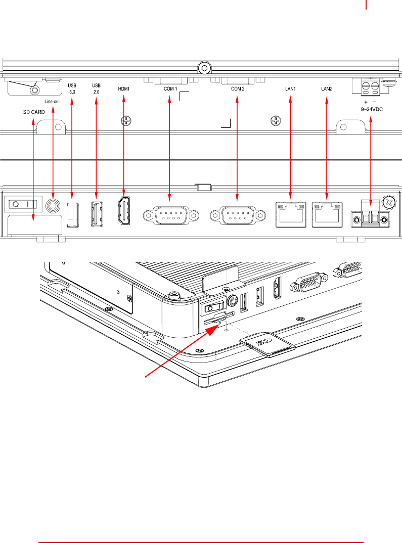
2.2 I/O Panel Layout
Figure 2-1: STC-1005/1205/1505 Rear I/O Layout
System Reset
10 System Description
2.3 Pin Definitions
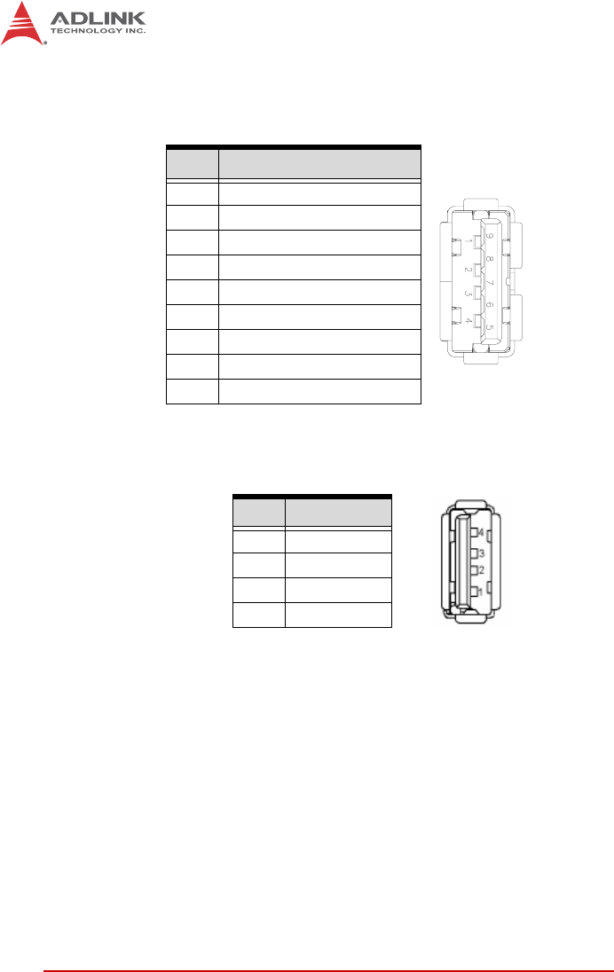
USB 3.0 Connectors
Table 2-1: USB 3.0 Port Pinout
USB 2.0 Connector
Table 2-2: USB 2.0 Port Pinout
Pin # Signal Name
1VCC
2 Data-
3 Data+
4GND
5RX_N
6RX_P
7GND
8TX_N
9TX_P
Pin # Signal Name
1Vcc
2 Data-
3Data+
4GND
System Description 11
STC-1005/1205/1505
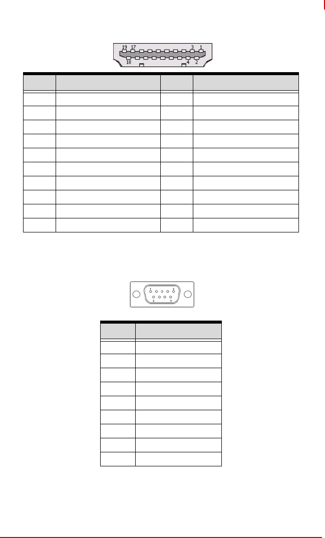
HDMI Connector
Table 2-3: HDMI Port Pinout
COM1/2 Ports (RS-232 TX/RX only)
Table 2-4: COM1/2 Port Pinouts
Pin # Signal Pin # Signal
1 TMDS Data2+ 2 TMDS Data2 Shield
3 TMDS Data2– 4 TMDS Data1+
5 TMDS Data1 Shield 6 TMDS Data1–
7 TMDS Data0+ 8 TMDS Data0 Shield
9 TMDS Data0– 10 TMDS Clock+
11 TMDS Clock Shield 12 TMDS Clock–
13 CEC 14 Reserved
15 SCL 16 SDA
17 DDC/CEC Ground 18 +5 V Power
19 Hot Plug Detect
Pin No RS-232
Pin1 -
Pin2 RX
Pin3 TX
Pin4 -
Pin5 GND
Pin6 -
Pin7 -
Pin8 -
Pin9 -
Pin 5
Pin 9
Pin 1
Pin 6
12 System Description
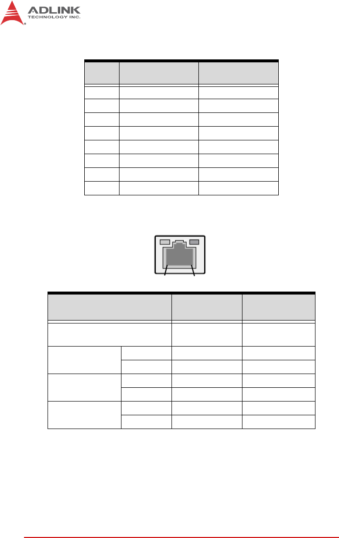
RJ-45 Gigabit Ethernet Connectors
Table 2-5: RJ-45 GbE Pin Definitions
Table 2-6: LAN LED Status Definitions
Pin # 10BASE-
T/100BASE-TX 1000BASE-T
1TX+ MDI0+
2TX- MDI0-
3RX+ MDI1+
4— MDI2+
5— MDI2-
6RX- MDI1-
7— MDI3+
8— MDI3-
Status Speed LED
(Green/Orange) Activity LED
(Yellow)
Network link is not established
or system powered off OFF OFF
10 Mbps Link OFF ON
Active OFF Blinking
100 Mbps Link Green ON
Active Green Blinking
1000 Mbps Link Orange ON
Active Orange Blinking
Activity
Speed
18

System Description 13
STC-1005/1205/1505
DC Power Input Connector
Table 2-7: DC Power Input Pinout

14 System Description
This page intentionally left blank.

Getting Started 15
STC-1005/1205/1505
3 Getting Started
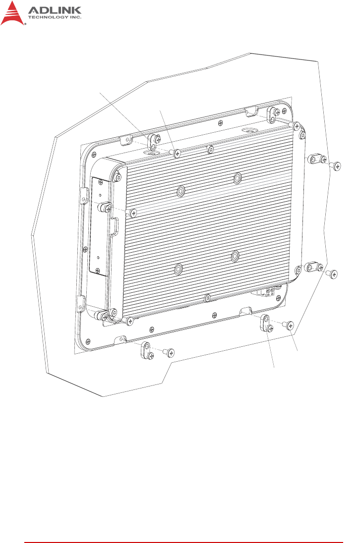
3.1 Panel Mounting
The STC-1005/1205/1505 can be panel mounted using the
8 brackets included with the device. Make sure there is adequate
space behind the panel for ventilation, and that the panel material
and thickness can support the weight of the device.
1. Cut the panel opening using the appropriate cutout
dimensions shown below.
2. Install the panel mount brackets onto the back of the
device as shown in Figure 3-1 below.
3. Attach I/O cables to the device before installing into the
panel if rear access will be limited after installation (see
“I/O Panel Layout” on page 9.).
4. Place the device into the panel cutout.
5. Hand-tighten the mounting brackets with a Phillips-head
screwdriver to secure it to the panel. Do not overtighten
the brackets to avoid damaging the device enclosure.
NOTE:
NOTE:
The mounting brackets can accommodate a maximum panel
thickness of 2 mm.
CAUTION:
Do not overtighten the brackets as this may damage the device
enclosure.Always tighten the mounting brackets BY HAND to
secure it to the panel.
16 Getting Started
Figure 3-1: Panel Mount Installation
Panel Mount Bracket
M4 Screw
Panel Mount Bracket
M4 Screw
Getting Started 17
STC-1005/1205/1505
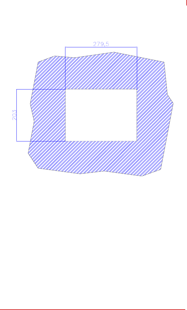
Panel Mount Cutout Dimensions
Figure 3-2: STC-1005 Panel Mount Cutout Dimensions
Dimensions in mm
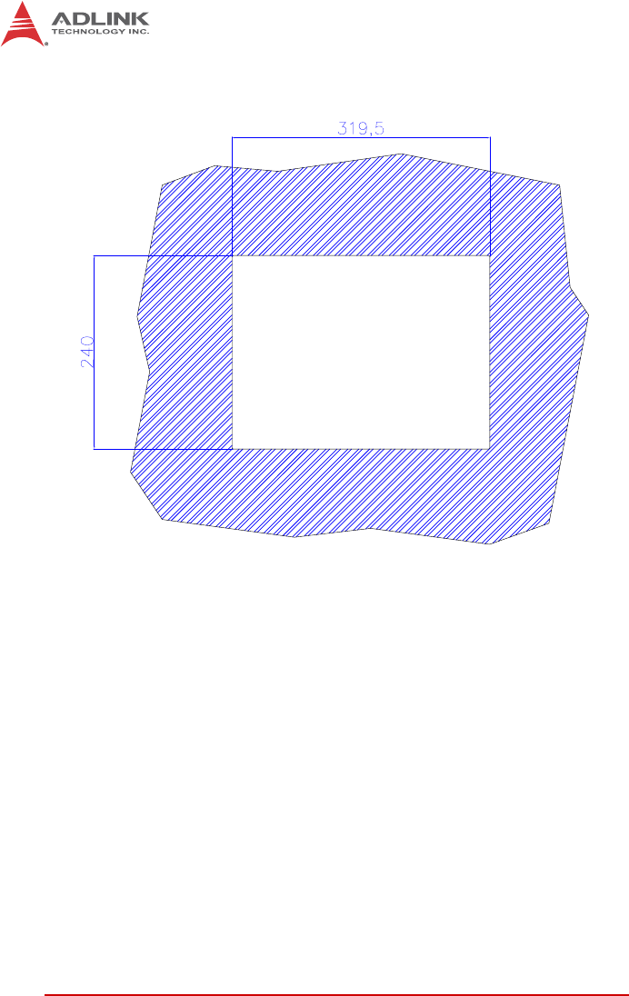
18 Getting Started
Figure 3-3: STC-1205 Panel Mount Cutout Dimensions
Dimensions in mm
Getting Started 19
STC-1005/1205/1505
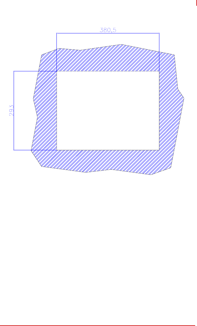
Figure 3-4: STC-1505 Panel Mount Cutout Dimensions
Dimensions in mm
20 Getting Started
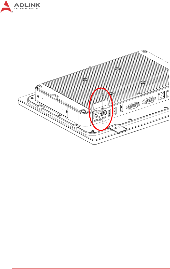
3.2 SD Card Installation
To install or remove the SD card, loosen the screw securing the
SD card slot cover. Insert or remove the SD card as required.
Figure 3-5: SD Card Installation (STC-1005 shown)
Replace the slot cover and tighten the scew.
Getting Started 21
STC-1005/1205/1505
3.3 STC-1005 SATA Slim Drive Installation
To install or replace a SATA Slim drive in the STC-1005, loosen
the screws securing the drive bay bracket from the device as
shown. Install the drive with the screws provided.
Figure 3-6: STC-1005 SATA Slim Drive Installation
22 Getting Started
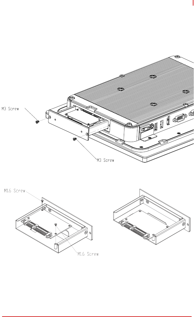
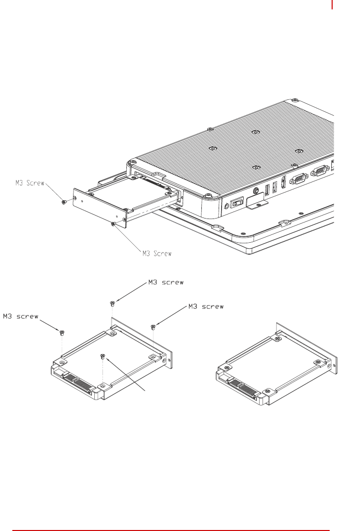
3.4 STC-1205/1505 SATA Slim Drive Installation
To install or replace a SATA Slim drive in the STC-1205/1505,
loosen the screws securing the drive bay bracket from the device
as shown. Install the drive with the screws provided.
Figure 3-7: STC-1205/1505 SATA Slim Drive Installation (STC-1205 shown)
Getting Started 23
STC-1005/1205/1505
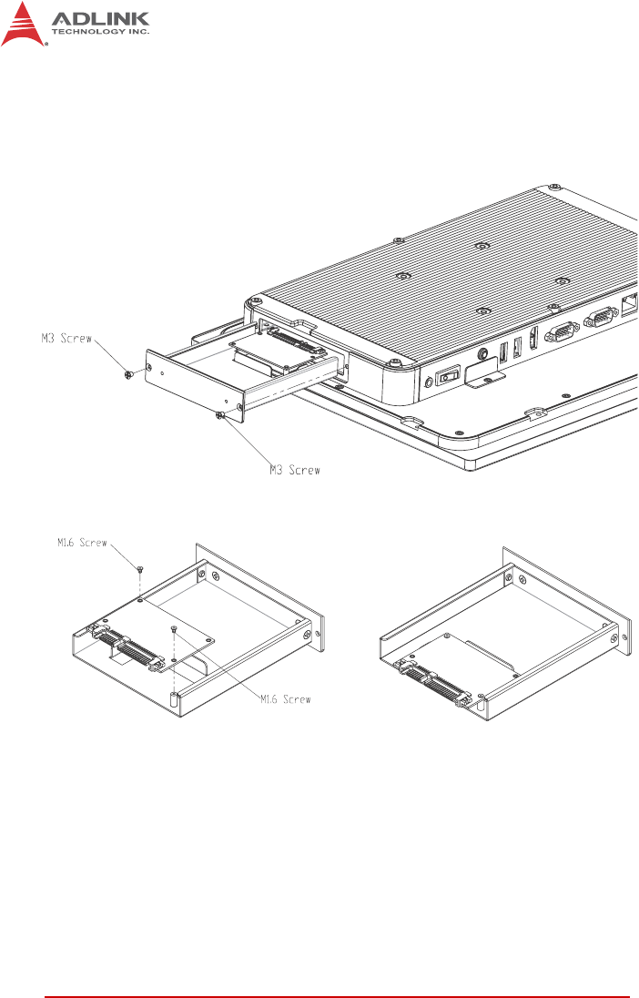
3.5 STC-1205/1505 2.5” SATA Drive Installation
To install or replace a 2.5” SATA drive in the STC-1205/1505,
loosen the screws securing the drive bay bracket from the device
as shown. Install the drive with the screws provided.
Figure 3-8: STC-1205/1505 2.5” SATA Drive Installation (STC-1205 shown)
24 Getting Started
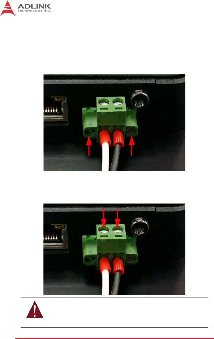
3.6 Connecting Power
An AC power adapter (19VDC, 65W) is included with the
STC-1005/1205/1505. To connect power to the device, insert the
pluggable terminal block on the end of the power supply into the
DC power inlet as shown below. Secure the terminal block by
tightening the two screws as indicated.
To connect a different DC power supply to the device, loosen the
screws securing the power leads to the terminal block indicated
below and connect the desired power supply with polarity as
shown.
WARNING:
Make sure the power supply is turned OFF when inserting the
terminal block or handling the power leads.

Getting Started 25
STC-1005/1205/1505
Powering Up the System
When DC power is turned on, the system will automatically boot
up. The power switch on the IO panel is an ATX switch.To shut
down the system, use the Windows shutdown procedure. To boot
the system after a soft shutdown, use the ATX switch or discon-
nect and reconnect DC power.

26 Getting Started
This page intentionally left blank.

Important Safety Instructions 27
STC-1005/1205/1505
Important Safety Instructions
For user safety, please read and follow all instructions,
WARNINGS, CAUTIONS, and NOTES marked in this manual and
on the associated equipment before handling/operating the
equipment.
XRead these safety instructions carefully.
XKeep this user’s manual for future reference.
XRead the specifications section of this manual for detailed
information on the operating environment of this equipment.
XWhen installing/mounting or uninstalling/removing
equipment:
ZTurn off power and unplug any power cords/cables.
XTo avoid electrical shock and/or damage to equipment:
ZKeep equipment away from water or liquid sources;
ZKeep equipment away from high heat or high humidity;
ZKeep equipment properly ventilated (do not block or
cover ventilation openings);
ZMake sure to use recommended voltage and power
source settings;
ZAlways install and operate equipment near an easily
accessible electrical socket-outlet;
ZSecure the power cord (do not place any object on/over
the power cord);
ZOnly install/attach and operate equipment on stable
surfaces and/or recommended mountings; and,
ZIf the equipment will not be used for long periods of time,
turn off and unplug the equipment from its power source.

28 Important Safety Instructions
A Lithium-type battery may be provided for backup power.
XNever attempt to fix the equipment. Equipment should only
be serviced by qualified personnel.
XEquipment must be serviced by authorized technicians
when:
ZThe power cord or plug is damaged;
ZLiquid has penetrated the equipment;
ZIt has been exposed to high humidity/moisture;
ZIt is not functioning or does not function according to the
user’s manual;
ZIt has been dropped and/or damaged; and/or,
ZIt has an obvious sign of breakage.
WARNING:
Risk of explosion if battery is replaced with one of an incorrect
type. Dispose of used batteries appropriately.

Getting Service 29
STC-1005/1205/1505
Getting Service
Contact us should you require any service or assistance.
ADLINK Technology, Inc.
Address: 9F, No.166 Jian Yi Road, Zhonghe District
New Taipei City 235, Taiwan
ᄅקؑխࡉ৬ԫሁ 166 ᇆ9ᑔ
Tel: +886-2-8226-5877
Fax: +886-2-8226-5717
Email: service@adlinktech.com
Ampro ADLINK Technology, Inc.
Address: 5215 Hellyer Avenue, #110
San Jose, CA 95138, USA
Tel: +1-408-360-0200
Toll Free: +1-800-966-5200 (USA only)
Fax: +1-408-360-0222
Email: info@adlinktech.com
ADLINK Technology (China) Co., Ltd.
Address: Ϟ⍋Ꮦ⌺ϰᮄऎᓴ∳催⾥ᡔುऎ㢇䏃 300 ো(201203)
300 Fang Chun Rd., Zhangjiang Hi-Tech Park
Pudong New Area, Shanghai, 201203 China
Tel: +86-21-5132-8988
Fax: +86-21-5132-3588
Email: market@adlinktech.com
ADLINK Technology Beijing
Address: ࣫ҀᏖ⍋⎔ऎϞഄϰ䏃 1োⲜ߯ࡼॺ Eᑻ801 ᅸ(100085)
Rm. 801, Power Creative E, No. 1 Shang Di East Rd.
Beijing, 100085 China
Tel: +86-10-5885-8666
Fax: +86-10-5885-8626
Email: market@adlinktech.com
ADLINK Technology Shenzhen
Address: ⏅ഇᏖफቅऎ⾥ᡔುफऎ催ᮄफϗ䘧᭄ᄫᡔᴃು
A1 ᷟ2ὐCऎ (518057)
2F, C Block, Bldg. A1, Cyber-Tech Zone, Gao Xin Ave. Sec. 7
High-Tech Industrial Park S., Shenzhen, 518054 China
Tel: +86-755-2643-4858
Fax: +86-755-2664-6353
Email: market@adlinktech.com
LiPPERT ADLINK Technology GmbH
Address: Hans-Thoma-Strasse 11, D-68163
Mannheim, Germany
Tel: +49-621-43214-0
Fax: +49-621 43214-30
Email: emea@adlinktech.com

30 Getting Service
ADLINK Technology, Inc. (French Liaison Office)
Address: 6 allée de Londres, Immeuble Ceylan
91940 Les Ulis, France
Tel: +33 (0) 1 60 12 35 66
Fax: +33 (0) 1 60 12 35 66
Email: france@adlinktech.com
ADLINK Technology Japan Corporation
Address: ͱ101-0045 ᵅҀ䛑गҷ⬄ऎ⼲⬄䤯ފ⬎ 3-7-4
⼲⬄ 374 ɛɳ 4F
KANDA374 Bldg. 4F, 3-7-4 Kanda Kajicho,
Chiyoda-ku, Tokyo 101-0045, Japan
Tel: +81-3-4455-3722
Fax: +81-3-5209-6013
Email: japan@adlinktech.com
ADLINK Technology, Inc. (Korean Liaison Office)
Address: 137-881 昢殾柢 昢爎割 昢爎堆嵢 326, 802 (昢爎壟,微汾瘶捒娯)
802, Mointer B/D, 326 Seocho-daero, Seocho-Gu,
Seoul 137-881, Korea
Tel: +82-2-2057-0565
Fax: +82-2-2057-0563
Email: korea@adlinktech.com
ADLINK Technology Singapore Pte. Ltd.
Address: 84 Genting Lane #07-02A, Cityneon Design Centre
Singapore 349584
Tel: +65-6844-2261
Fax: +65-6844-2263
Email: singapore@adlinktech.com
ADLINK Technology Singapore Pte. Ltd. (Indian Liaison Office)
Address: #50-56, First Floor, Spearhead Towers
Margosa Main Road (between 16th/17th Cross)
Malleswaram, Bangalore - 560 055, India
Tel: +91-80-65605817, +91-80-42246107
Fax: +91-80-23464606
Email: india@adlinktech.com
ADLINK Technology, Inc. (Israeli Liaison Office)
Address: 27 Maskit St., Corex Building
PO Box 12777
Herzliya 4673300, Israel
Tel: +972-54-632-5251
Fax: +972-77-208-0230
Email: israel@adlinktech.com
ADLINK Technology, Inc. (UK Liaison Office)
Tel: +44 774 010 59 65
Email: UK@adlinktech.com