ADRF KOREA ADX-R-A43M Remote Unite (Distribute Antenna System) User Manual ADX DAS HRU
ADRF KOREA, Inc. Remote Unite (Distribute Antenna System) ADX DAS HRU
UserManual.wiki
>
ADRF KOREA
>
ADX R A43M User Manual
User Manual
Navigation menu
Upload a User Manual
Namespaces
Wiki Guide
HTML
PDF
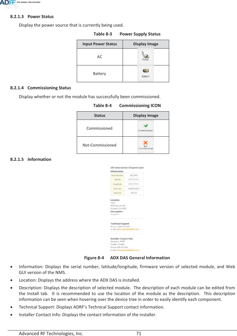
Info
Views
User Manual
Discussion / Help
Navigation

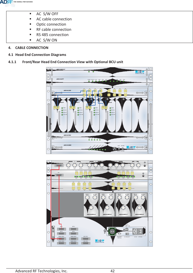
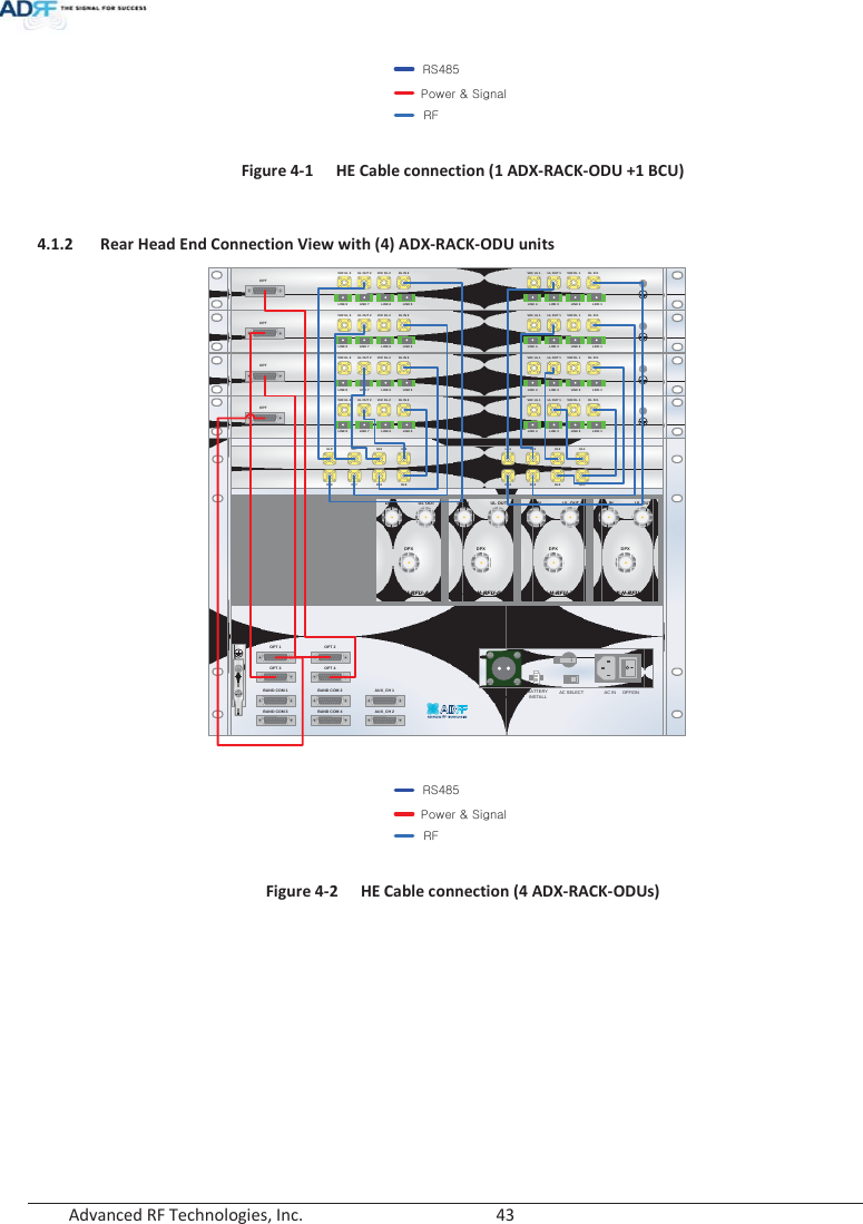
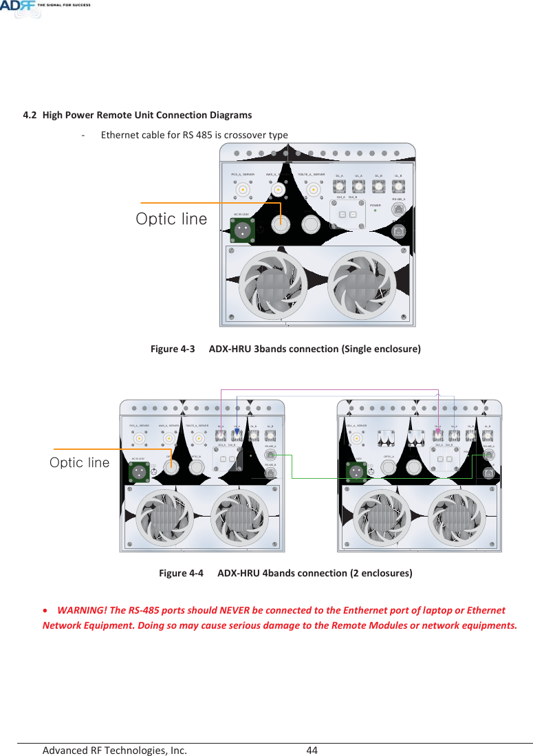
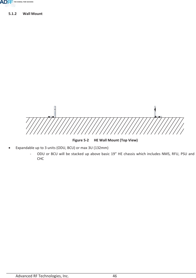
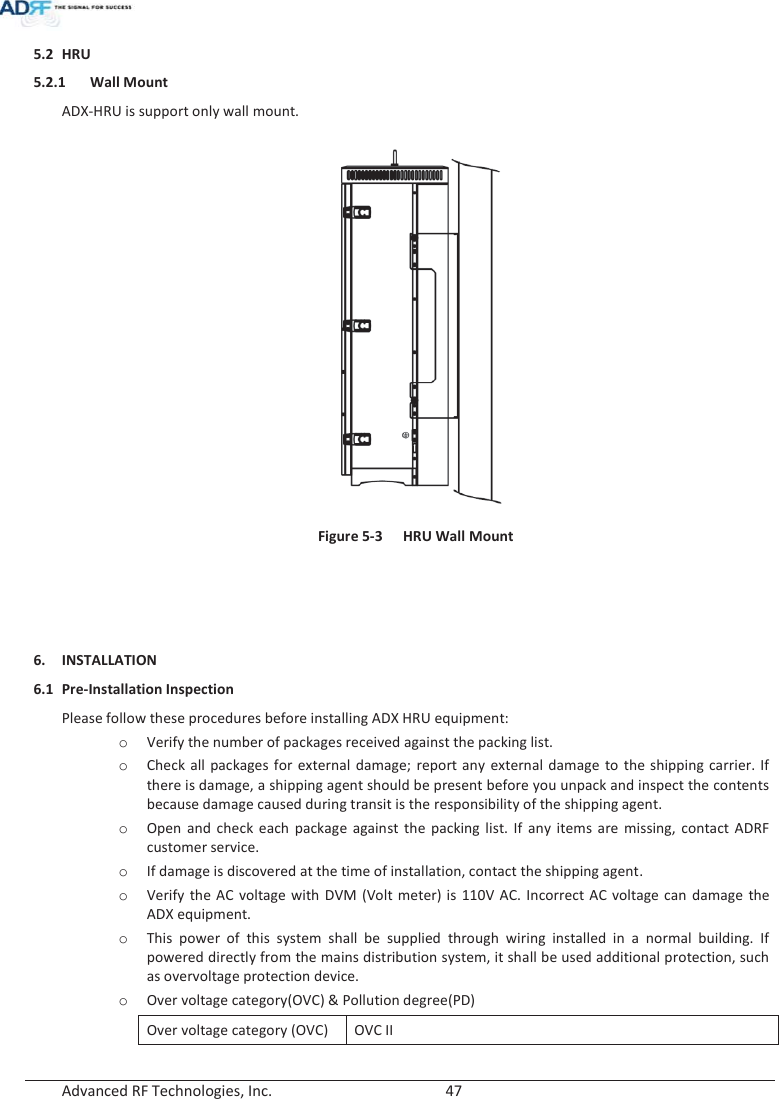
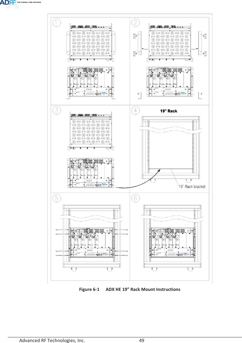
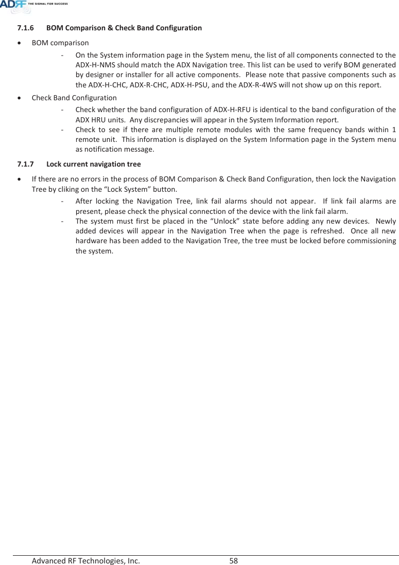
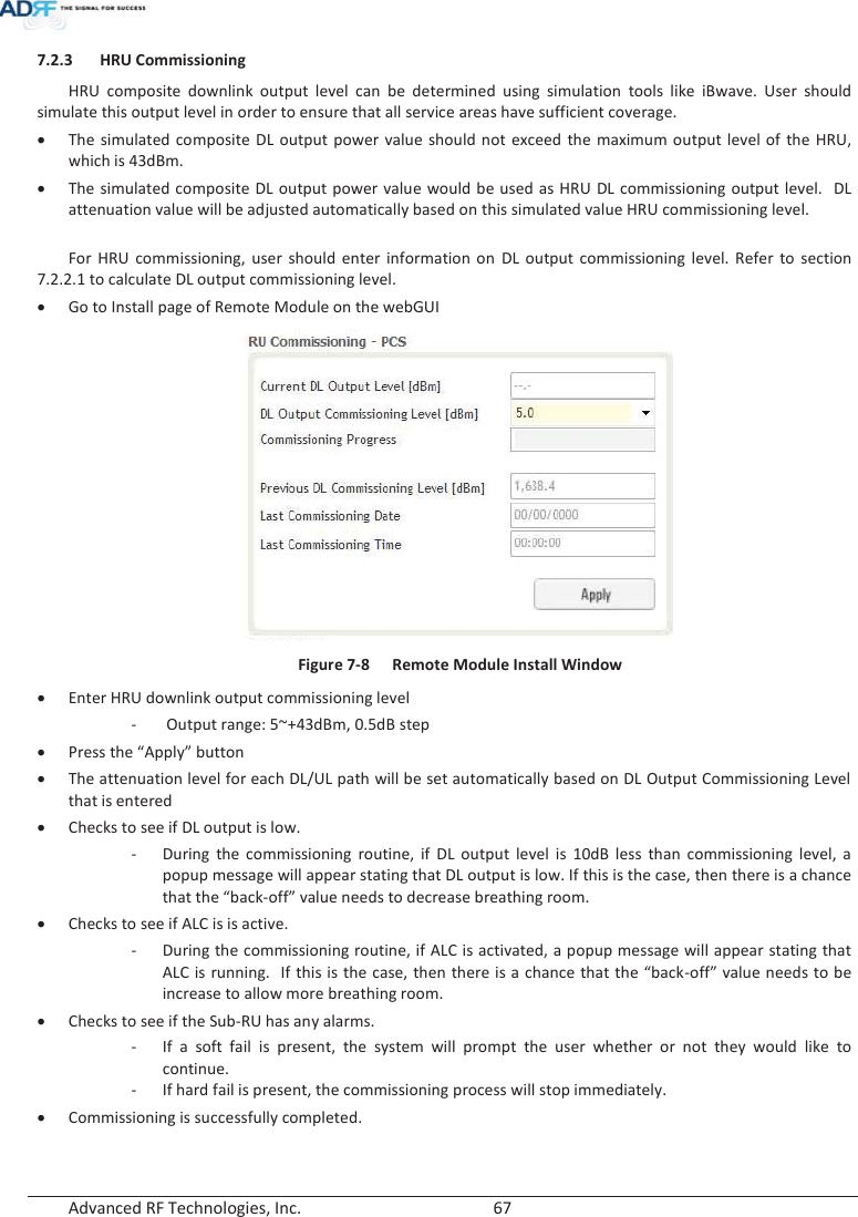
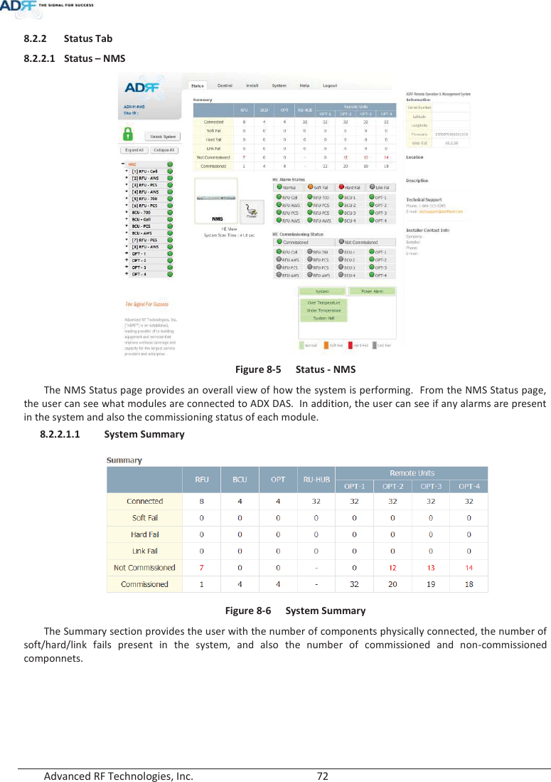
![Advanced RF Technologies, Inc. 22 1.5 Warnings and Hazards Opening or tampering the ADX DAS will void all warranties. WARRANTY Actual separation distance is determined upon gain of antenna used. Please maintain a minimum safe distance of at least 100cm while operating near the donor and the server antennas. Also, the donor antenna needs to be mounted outdoors on a permanent structure. RF EXPOSURE & ANTENNA PLACEMENT Guidelines Working with the ADX DAS while in operation, may expose the technician to RF electromagnetic fields that exceed FCC rules for human exposure. Visit the FCC website at www.fcc.gov/oet/rfsafety to learn more about the effects of exposure to RF electromagnetic fields. WARNING! EXPOSURE TO RF Opening the ADX DAS could result in electric shock and may cause severe injury. WARNING! ELECTRIC SHOCK ָ֦ [Y1]: ܹࢽ 50Æ100cm 2014/05/29](https://usermanual.wiki/ADRF-KOREA/ADX-R-A43M/User-Guide-2287108-Page-22.png)
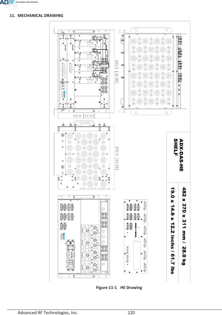
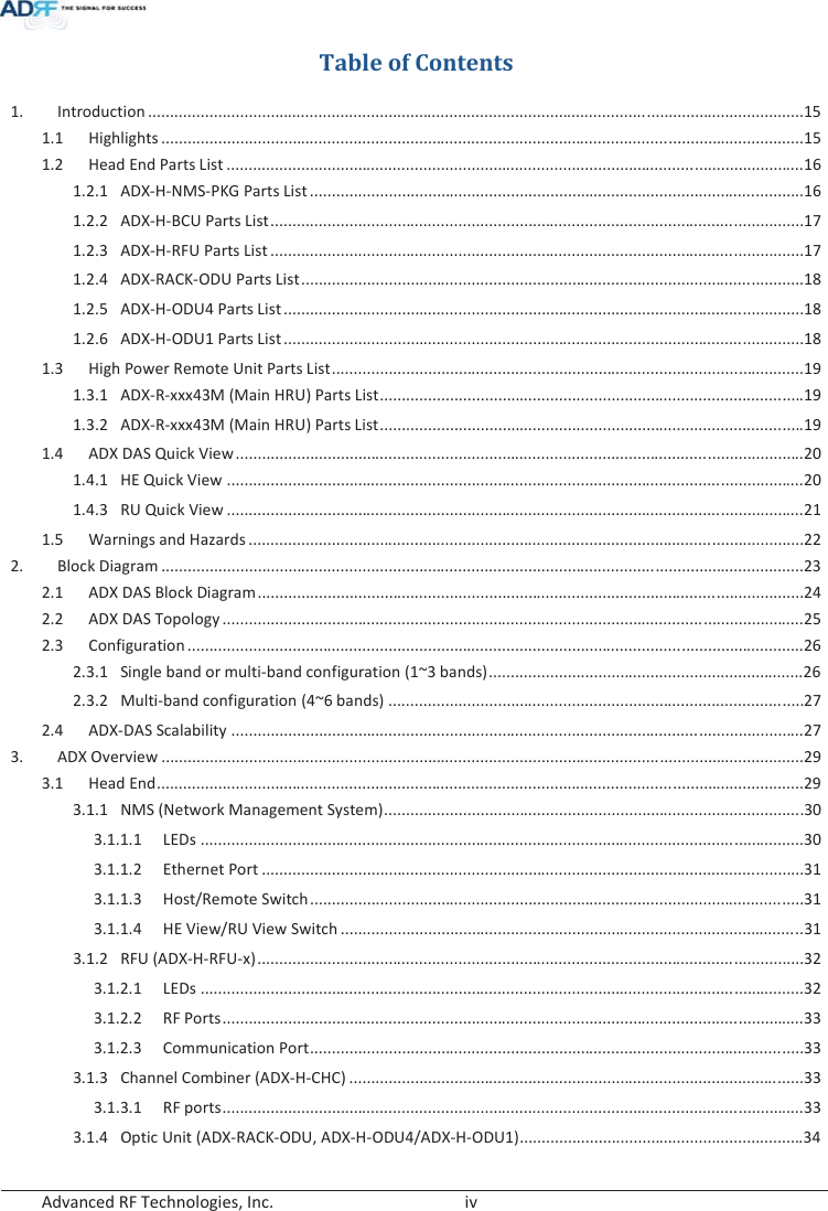
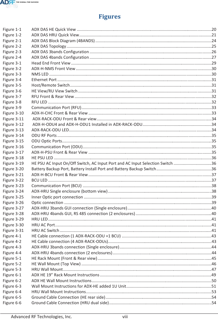
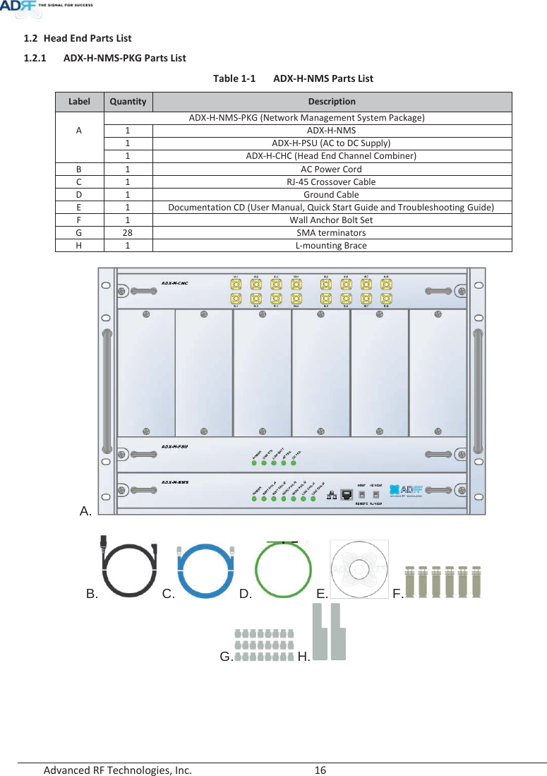
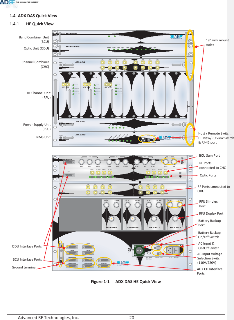
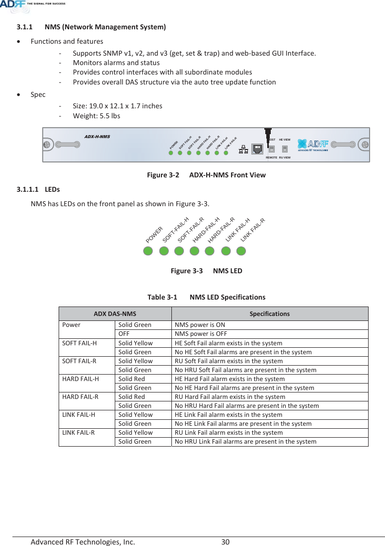
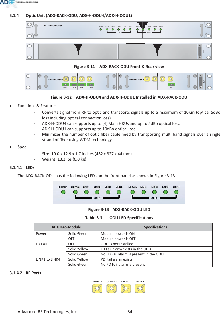
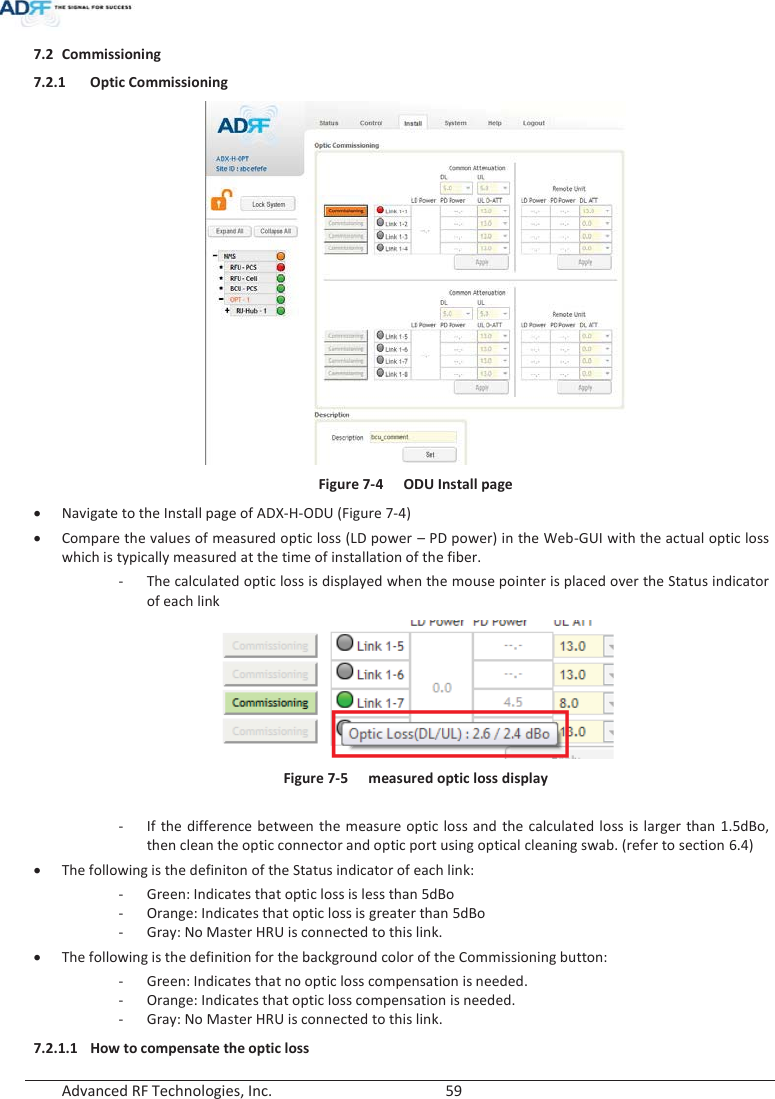
![Advanced RF Technologies, Inc. 29 3. ADX OVERVIEW 3.1 Head End Head end components include: ADX-H-NMS (Network Management System) ADX-H-CHC (Head End Channel Combiner) ADX-H-PSU (Head End Power Supply) Up to [4] ADX-H-BCU (Band Combiner Unit) Up to [8] ADX-H-RFU-x (RF Unit) Up to [4] ADX-RACK-ODU (Optical Unit) xSpecifications - Size: 19.0 x 14.6 x 12.2 inches (482 x 370 x 311 mm) - Weight: 83.7 lbs (38.0 Kg)@4 RFU, CHC-H, PSU and NMS - Power Consumption: 52W@4 RFU, 1 ADX-H-ODU4 and NMS, 28W@1 RFU, 1 ADX-H-ODU4 and NMS - Power Input: 110VAC or -48VDC(optional) - Supports the ADRF-BBU for external battery backup solution ADX-H-NMSPOWERSOFT FAIL-HSOFT FAIL-RHARD FAIL-HHARD FAIL-RLINK FAIL-HLINK FAIL-RHOST HE VIEWREMOTE RU VIEWADX-H-PSUPOWERCHG STSLOW BATTAC FAILDC FAILDL OUTUL INHARD FAILDL SIG LOWSOFT FAILPOWERADX-H-RFU-PDL OUTUL INHARD FAILDL SIG LOWSOFT FAILPOWERADX-H-RFU-7DL OUTUL INHARD FAILDL SIG LOWSOFT FAILPOWERADX-H-RFU-CDL OUTUL INHARD FAILDL SIG LOWSOFT FAILPOWERADX-H-RFU-AADX-H-CHCUL1 UL2 UL3 UL4DL1 DL2 DL3 DL4UL5 UL6 UL7 UL8DL5 DL6 DL7 DL8LD FAIL5-8 LINK5 LINK6 LINK7 LINK8LD FAIL1-4 LINK1 LINK2 LINK3 LINK4POWERADX-H-RACK-ODUSOFT FAILPOWERADX-H-BCU-P Figure 3-1 Head End Front View](https://usermanual.wiki/ADRF-KOREA/ADX-R-A43M/User-Guide-2287108-Page-29.png)
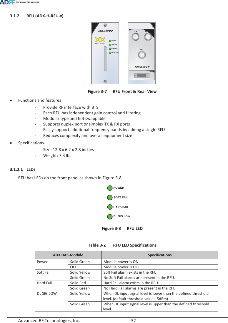
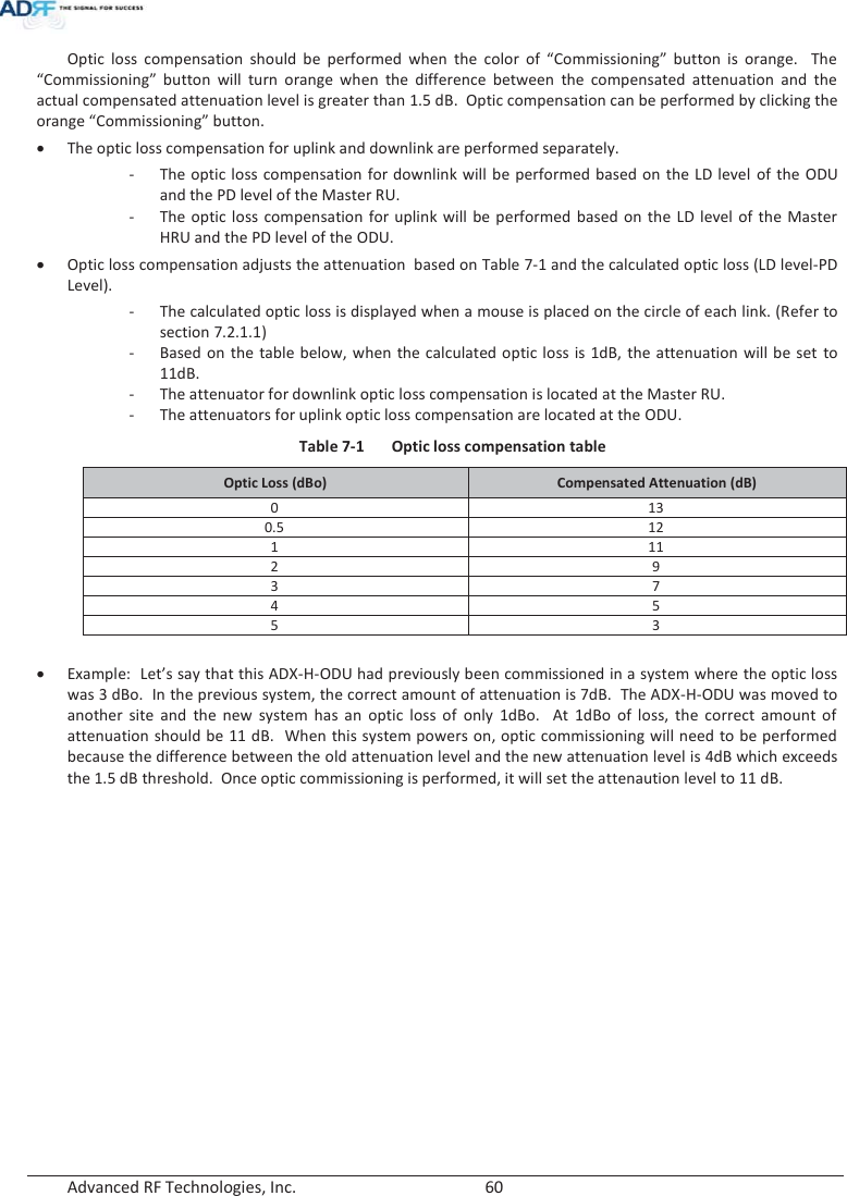
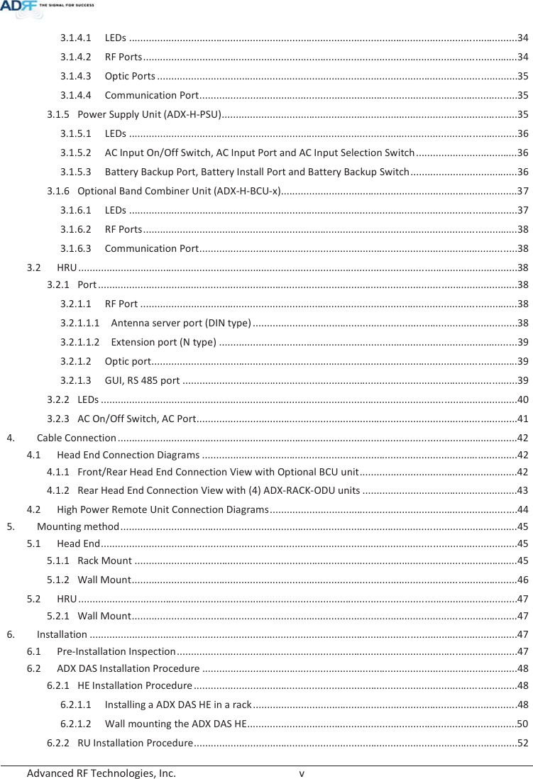
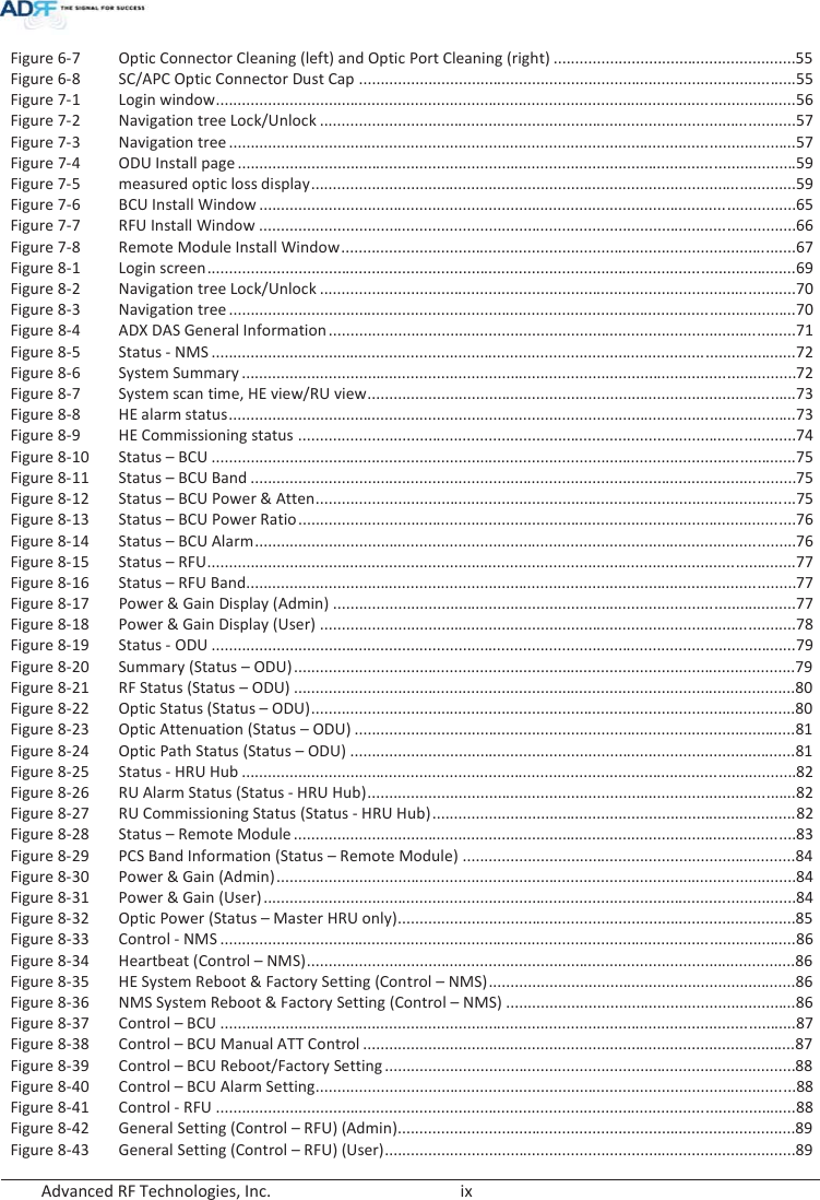
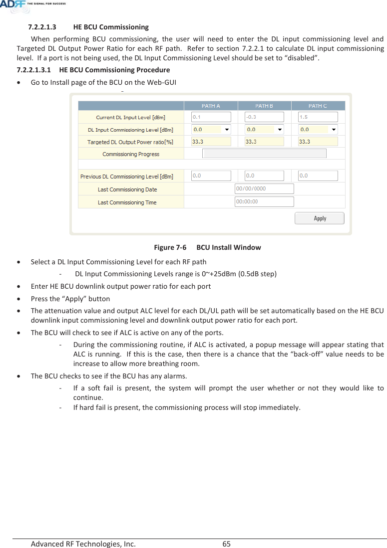
![Advanced RF Technologies, Inc. 64 - The attenuation and DL output ALC level for the other ports are set based on the formula below to keep the power ratio between BCU ports. !The maximum output power for the specified path = 10*log10[10^(Max_ALC/10)x(Pwr_Ratio)/ Max_Ratio] Max_ALC: DL output ALC level for the path with maximum power ratio = 5dBm Pwr_Ratio: Targeted DL output power ratio value for the specified path Max_Ratio: maximum power ratio value !The attenuation for the specified path = The targeted maximum input power for the specified path - The maximum output power for the specified path !DL output ALC level = The targeted maximum input power for the specified path - The attenuation for the specified path !The path for AT&T- CH2 The maximum output power = 10*log10[10^(5/10)x20%/50%] = 1.02dBm The ATT value = 18.0dBm-1.02dBm=16.98dB Î 16.5dB(the control step of used attenuator is 0.5dB) DL output ALC level = 18dBm – 16.5dB = 1.5dBm !The path for Sprint- CH1 The maximum output power = 10*log10[10^(5/10)x30%/50%] = 2.78dBm The ATT value = 9.0dBm-2.78dBm=6.22dB Î 6.0dB(the control step of used attenuator is 0.5dB) DL output ALC level = 9.0dBm – 6.0dB = 3.0dBm - The DL maximum output power of BCU is the sum of maximum output power for each port and this power becomes the HE RFU input commissioning level. - The maximum input level of HE RFU should be less than 10dBm (= 5dBm + 10*log10 (3)) because the maximum output of BCU per each path doesn’t exceed 5dBm by ALC function. Table 7-10 Maximum Output Power per carrier WSP Sprint AT&T VZW Targeted maximum input power 9.0dBm 18.0dBm 11.0dBm 19.2dBm Targeted DL Output Power Ratio set by user 30.0% 20.0% 50.0% DL maximum output power (ATT control step, 0.5dB is not considered) 2.78dBm 1.02dBm 5.0dBm ATT value 6.0dB 16.5dB 6.0dB DL output ALC level or DL Maximum output power (ATT control step, 0.5dB is considered) 3.0dBm 1.5dBm 5.0dBm 8.2dBm(RFU DL Input commissioning level) DL Output Power Ratio considering ATT control step 0.5dB 30.37% 21.50% 48.13%](https://usermanual.wiki/ADRF-KOREA/ADX-R-A43M/User-Guide-2287108-Page-64.png)
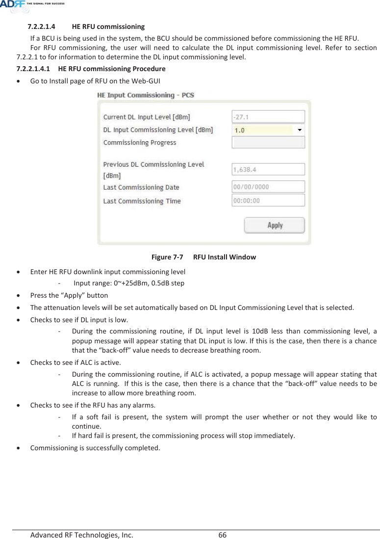
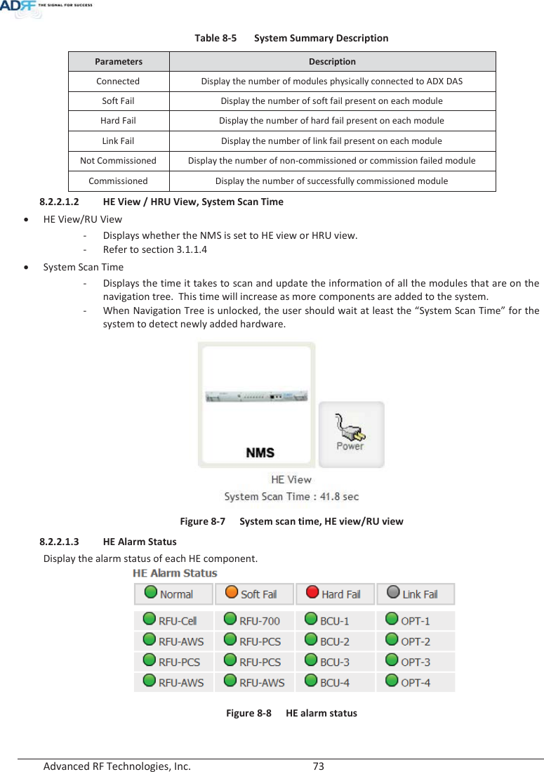
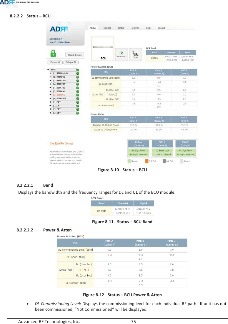
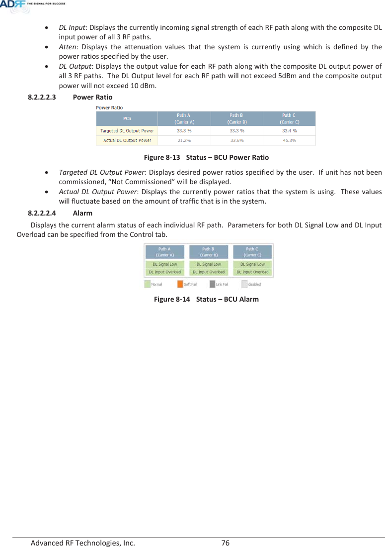
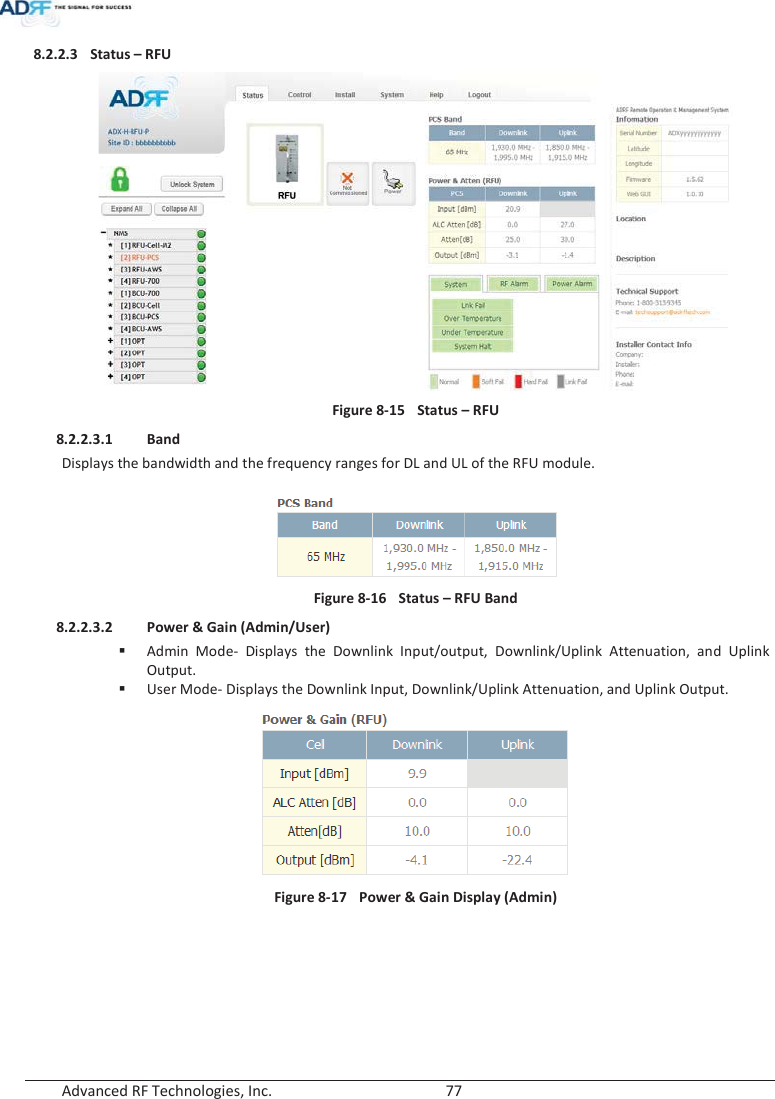
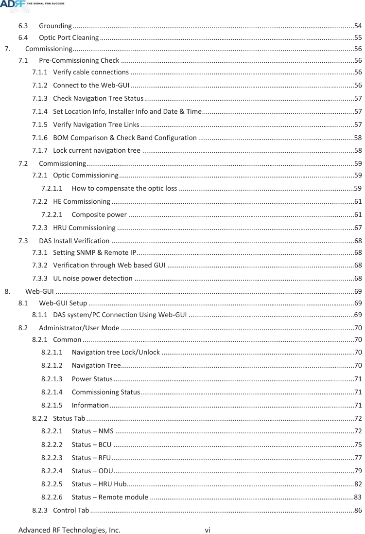
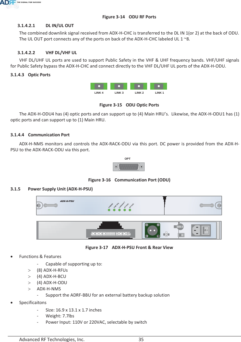
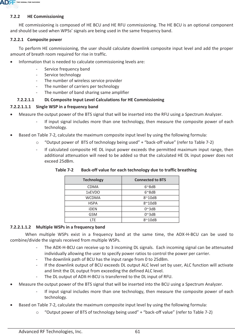
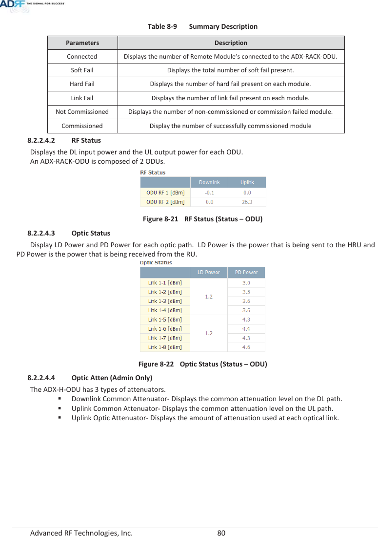
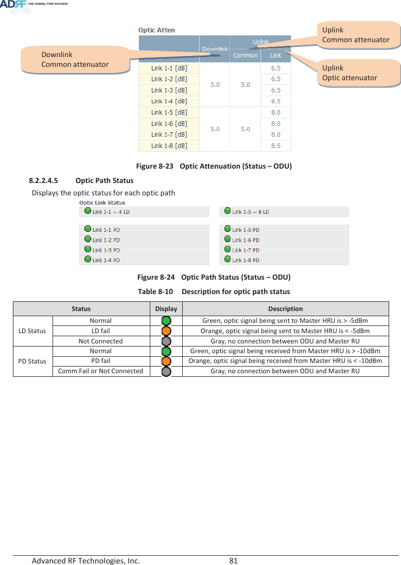
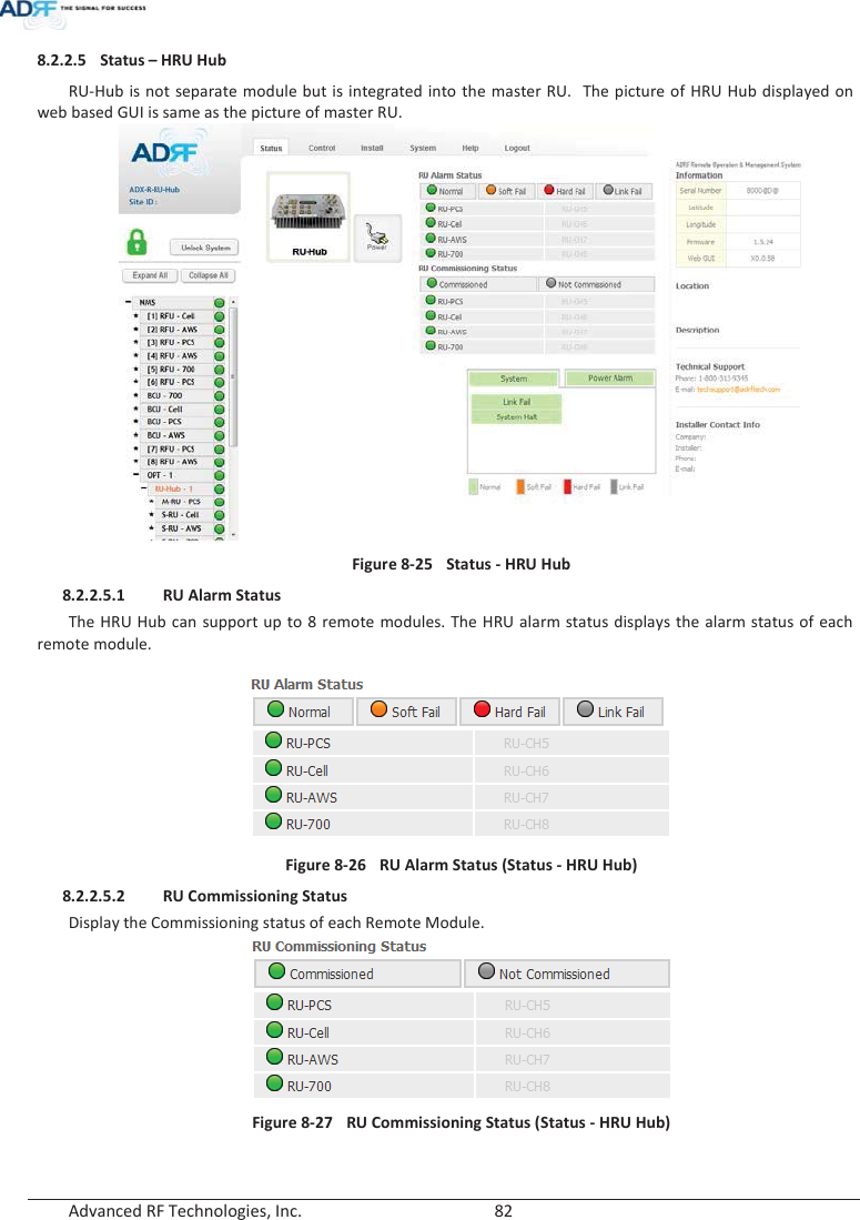
![Advanced RF Technologies, Inc. 78 Figure 8-18 Power & Gain Display (User) xInput [dBm]: Displays the Downlink RF input level which comes from the ADX-H-BCU or BTS. This value should be between 0 to 25 dBm. xALC Atten [dB]: The amount of attenuation that is being used by the system when ALC is active. xAtten [dB]: The amount of attenuation that has been set manually by the user. xOutput [dBm]: The downlink/uplink output power of the RFU and NOT the output power of the RU. 8.2.2.3.3 Alarm Displays System, RF, and Power Alarms. If an alarm is present in the system, then the color of the tab will change according to the type of failure. Table 8-8 RFU Alarm Status Alarm Severity Description System Link Fail Soft Fail A component is physically connected, but the NMS is unable to communicate with it. Over Temperature Hard Fail / Soft Fail The temperature of NMS is higher than the threshold level for over temperature alarm. Under Temperature Soft Fail The temperature of NMS is lower than the threshold level for under temperature alarm. System Halt Hard Fail System will go into a “System Halt” state when a hard fail alarm does not clear after 10 checks. System Halt can only be cleared with a power cycle, reboot, or factory settings. RF Alarm DL Signal not detected Soft Fail Downlink input signal is lower than the defined threshold by user. DL Signal Low Soft Fail Downlink input signal is lower than the defined threshold by user. Input Overload Hard Fail / Soft Fail Downlink input signal is higher than the defined threshold. Overpower Hard Fail / Soft Fail Uplink output signal is higher than the defined threshold by user. Power Alarm AC Fail Soft Fail AC power is not operating within parameters. DC Fail Soft Fail DC power is not operating within parameters. Over Current Hard Fail Total current of HE is higher than the threshold level for over current alarm. Battery Low Soft Fail Voltage of battery connected to HE PSU is lower than the defined threshold.](https://usermanual.wiki/ADRF-KOREA/ADX-R-A43M/User-Guide-2287108-Page-78.png)
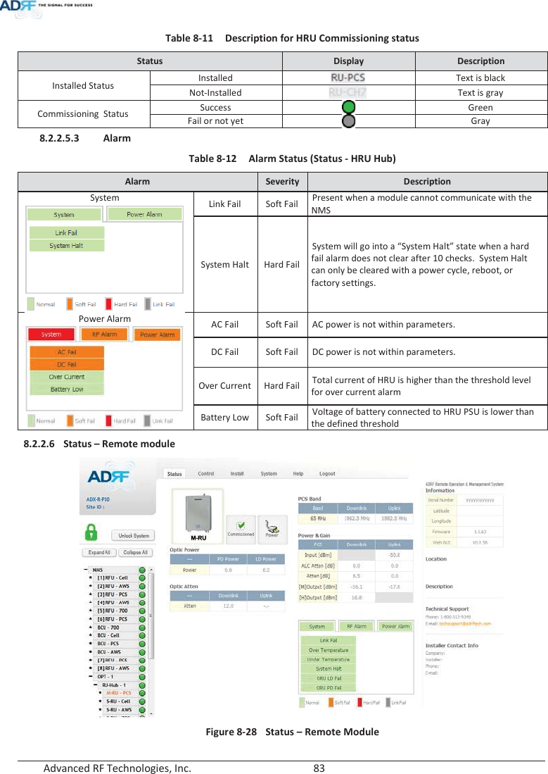
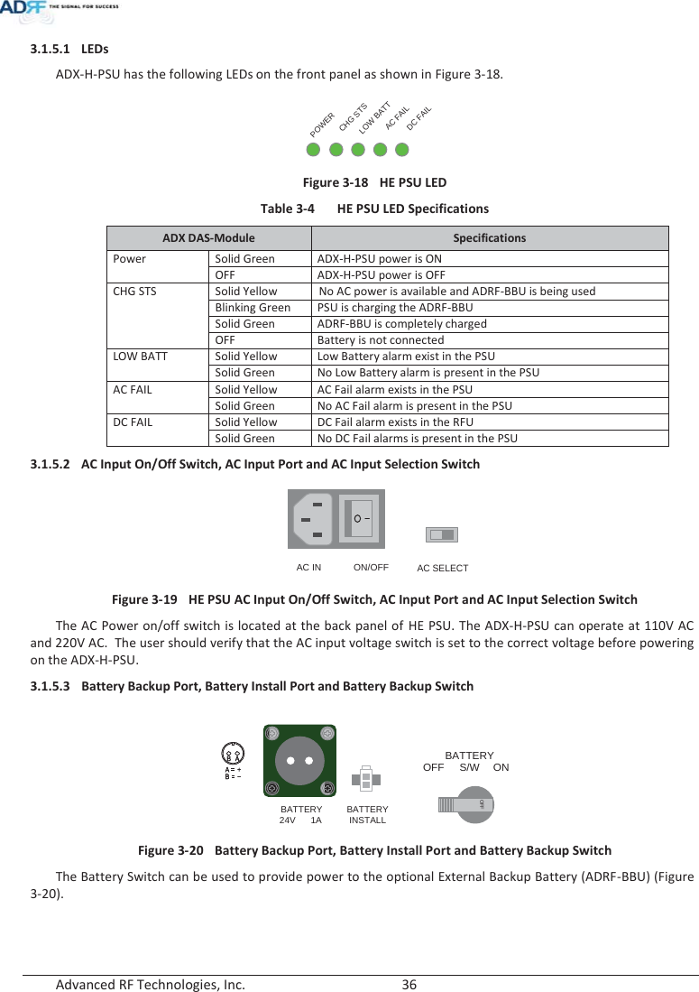
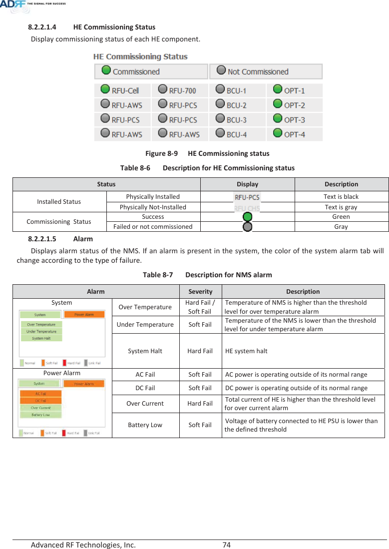
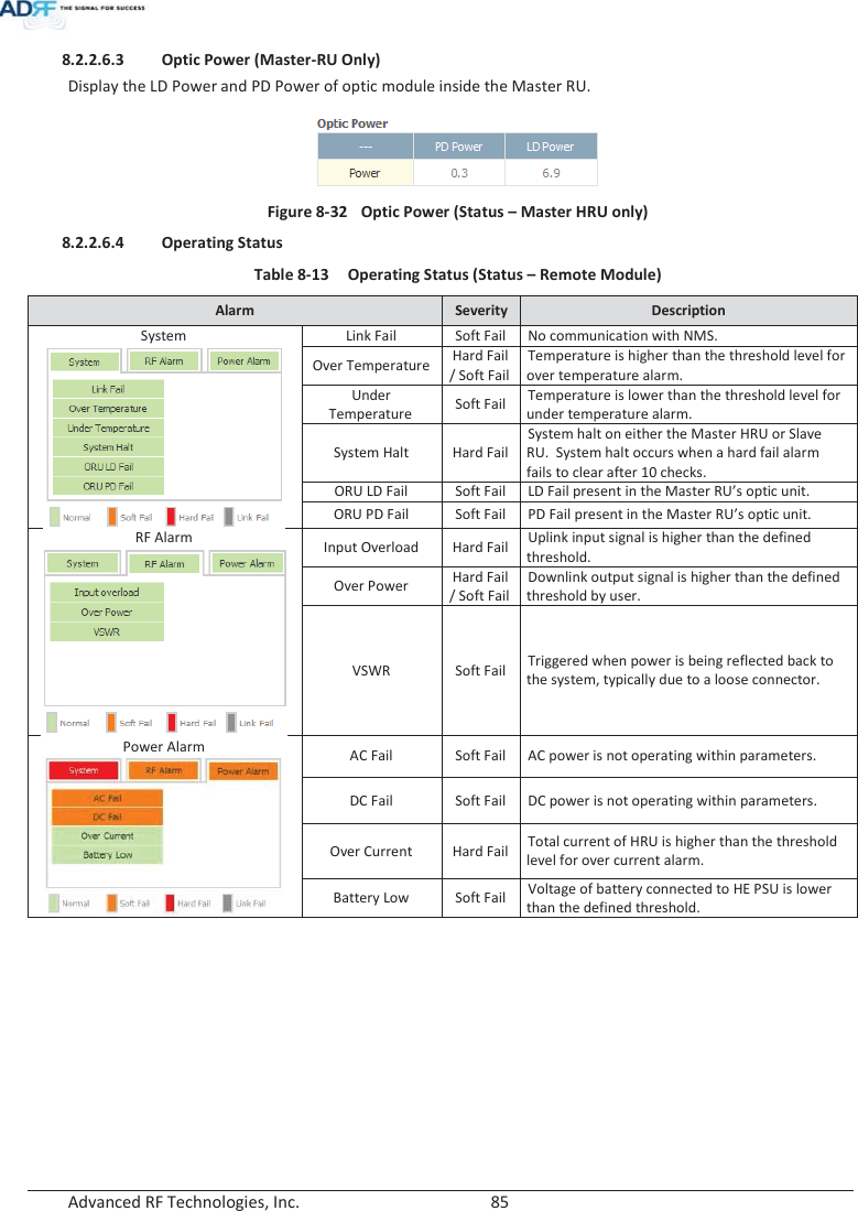
![Advanced RF Technologies, Inc. 84 8.2.2.6.1 Band Display the spectrum that is being used. The band column displays the bandwidth that has been used. The downlink column displays the center frequency of the used downlink band. The uplink column displays the center frequency of the used uplink band. Figure 8-29 PCS Band Information (Status – Remote Module) 8.2.2.6.2 Power & Gain (Admin/User) Display the Downlink output, Downlink/Uplink Attenuation, and Uplink Input/output. Figure 8-30 Power & Gain (Admin) Figure 8-31 Power & Gain (User) xAdmin oInput [dBm]: Displays the RF input level for Uplink only for the Remote Module. oALC Atten [dB]: The amount of attenuation used when ALC is activate. oAtten [dB]: The amount of attenuation manually set by the user. o[M]Output [dBm]: Output power of RF transceiver (1st stage amplification). o[H]Output [dBm]: Output power of downlink HPA (2nd stage amplification). xUser oInput [dBm]: Displays the RF input level for Uplink only for the Remote Module. oAtten [dB]: The amount of attenuation manually set by the user. oOutput [dBm]: Displays the total composite output power.](https://usermanual.wiki/ADRF-KOREA/ADX-R-A43M/User-Guide-2287108-Page-84.png)
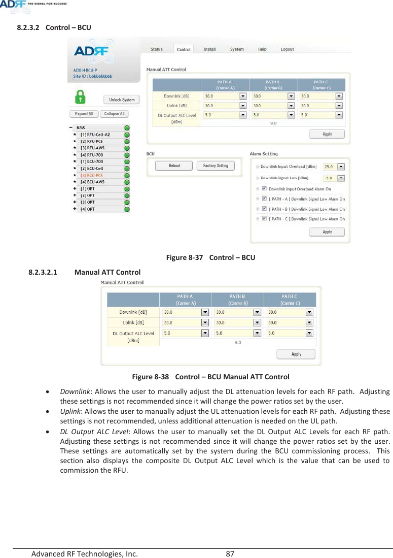
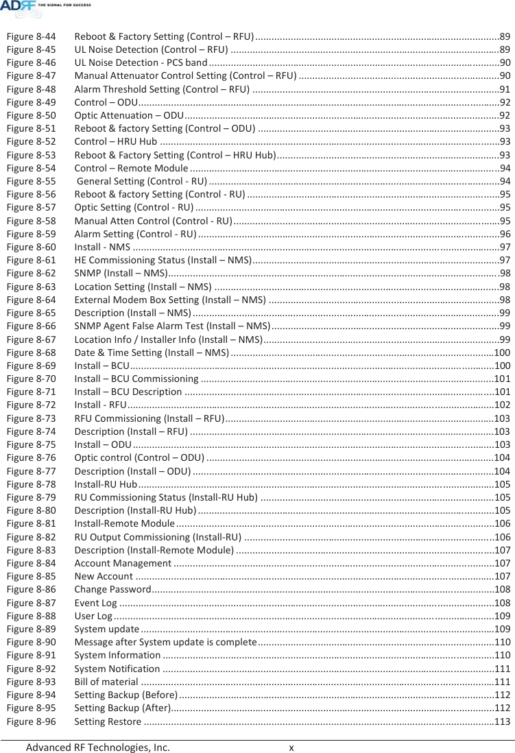
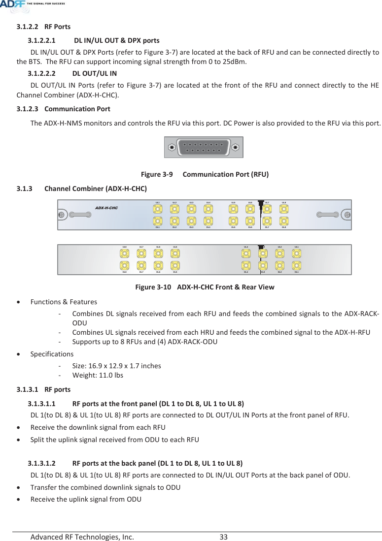
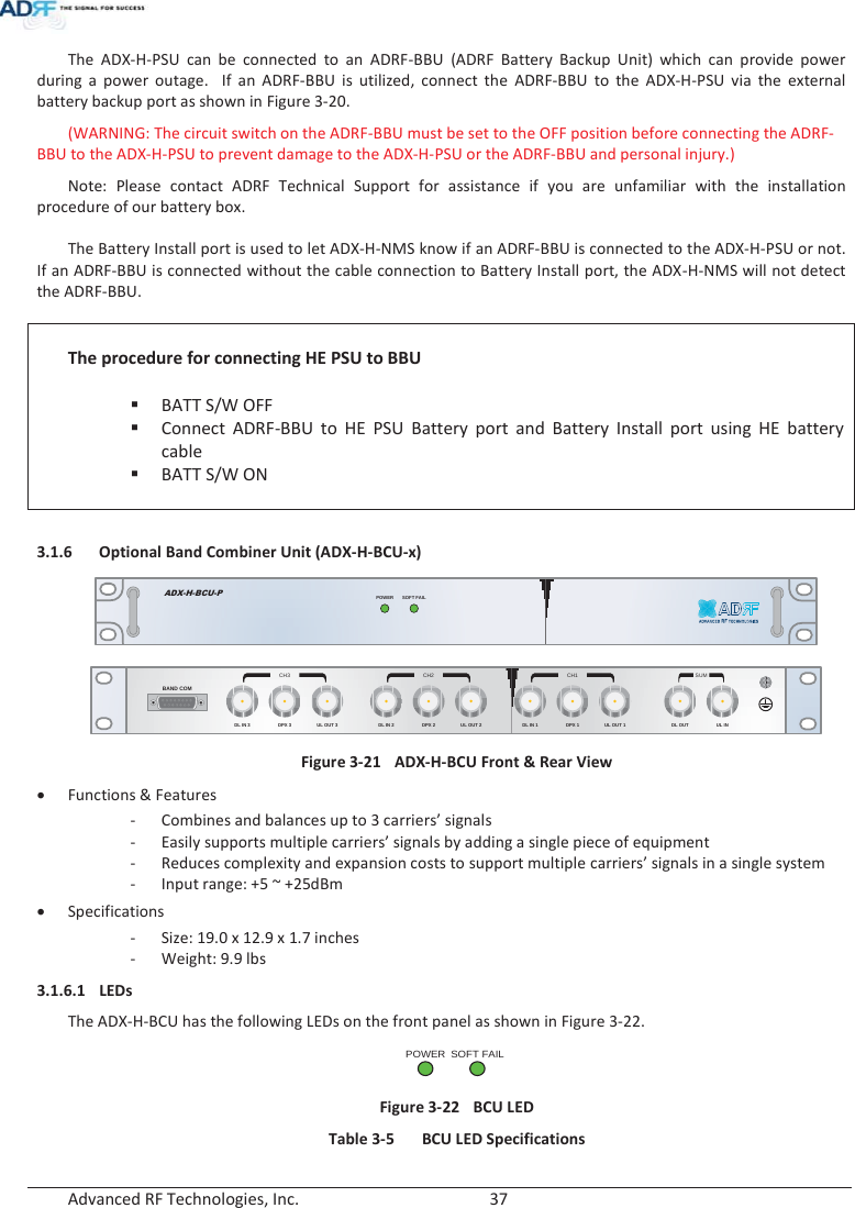
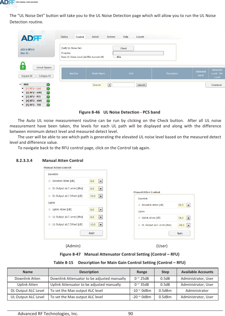
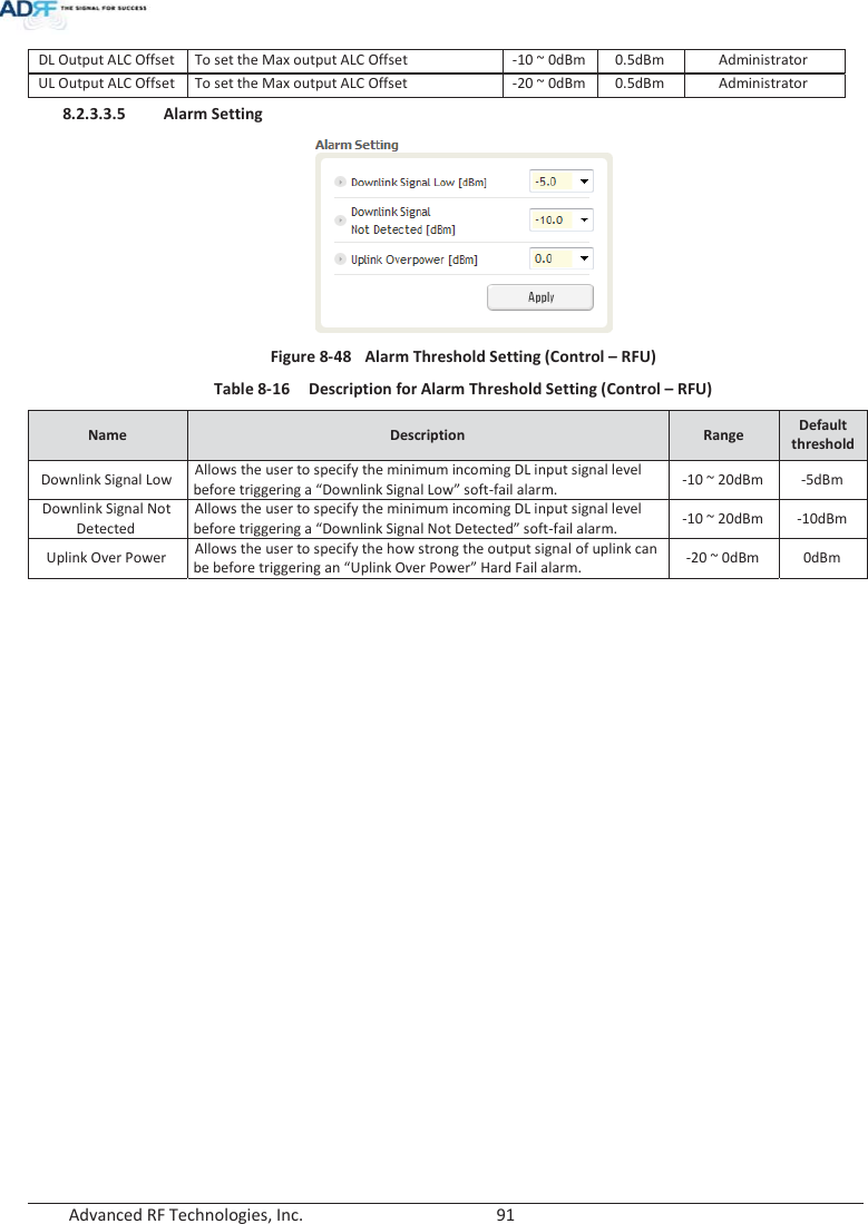
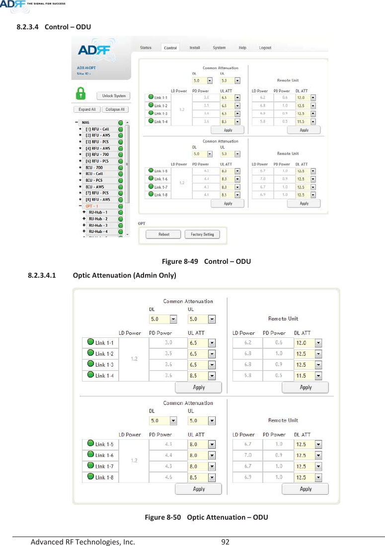
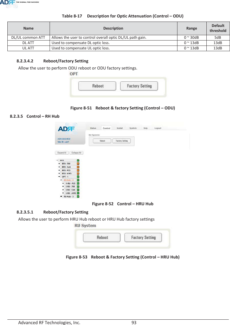
![Advanced RF Technologies, Inc. 88 8.2.3.2.2 Reboot / Factory Setting Allows the user reboot or restore factory settings of the BCU. Figure 8-39 Control – BCU Reboot/Factory Setting 8.2.3.2.3 Alarm Setting Figure 8-40 Control – BCU Alarm Setting xDownlink Input Overload: Allows the user to specify the level at which the DL Input Overload alarm is triggered. Values range from 0 dBm to +25 dBm. xDownlink Signal Low: Allows the user to specify the level at which the DL Signal Low alarm is triggered. Values range from -10 dBm to +20 dBm. xDownlink Input Overload Alarm On: Allows to user to enable or disable the Input Overload Alarm x[Path – A/B/C] Downlink Signal Low Alarm On: Allows the user to enable or disable the DL Signal Low alarm for each RF path. 8.2.3.3 Control – RFU Figure 8-41 Control - RFU](https://usermanual.wiki/ADRF-KOREA/ADX-R-A43M/User-Guide-2287108-Page-88.png)

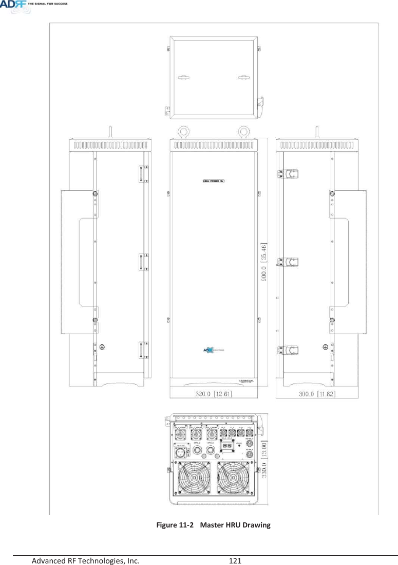
![Advanced RF Technologies, Inc. 116 9. SYSTEM-WIDE SPECIFICATION (TO BE CONNECTED TO HE VIA OPTIC LINE) 9.1 PCS band Item Specification Frequency Downlink 1930-1995MHz Uplink 1850-1915MHz DL Input Range at HE 0~25dBm Gain Range DL 18~43dB, 0.5dB step, ATT range: 0~25dB UL -5~30dB, 0.5dB step, ATT range: 0~35dB Accuracy 0~15dB: < ±0.5dB, 15~35dB: < ±1.0dB Gain Flatness < ±3.0dB Composite Maximum Output Power Downlink at HRU 43dBm±2dBUplink at HE -15dBm±2dB Noise Figure @max gain 7.0dBVSWR < 1:1.5 EVM < 8% Optical Loss0~5dBo(with ADX-H-ODU4)/0~10dBo(with ADX-H-ODU1) System Delay <2us @0dBo optic loss Spurious FCC, 3GPP TS 36.104, 3GPP2 C.S0010-C Operating Temperature -30-55qC Operating Humidity 5-90% Dimension (W x H x D) 12.6 x 35.5 x 11.8 in Weight 105.8 lbs.(without mounting bracket) Cooling Method Fan Mount Wall mount, Pole mount(optional) RF Connector DIN type female Weather Resistance IP56/NEMA 4X 9.2 AWS band Item Specification Frequency Downlink 2110-2155MHz ָ֦ [Y2]: Correction 14/05/08 ָ֦ [Y3]: Correction 14/05/08 ָ֦ [Y4]: Correction 14/05/08](https://usermanual.wiki/ADRF-KOREA/ADX-R-A43M/User-Guide-2287108-Page-116.png)
![Advanced RF Technologies, Inc. 117 Uplink 1710-1755MHz DL Input Range at HE 0~25dBm Gain Range DL 18~43dB, 0.5dB step, ATT range: 0~25dB UL -5~30dB, 0.5dB step, ATT range: 0~35dB Accuracy 0~15dB: < ±0.5dB, 15~35dB: < ±1.0dB Gain Flatness < ±3.0dB Composite Maximum Output Power Downlink at HRU 43dBm±2dB Uplink at HE -15dBm±2dB Noise Figure @max gain 7.0dBVSWR < 1:1.5 EVM < 8% Optical Loss0~5dBo(with ADX-H-ODU4)/0~10dBo(with ADX-H-ODU1) System Delay <2us @0dBo optic loss Spurious FCC, 3GPP TS 36.104, 3GPP2 C.S0010-C Operating Temperature -30-55qC Operating Humidity 5-90% Dimension (W x H x D) 12.6 x 35.5 x 11.8 in Weight 105.8 lbs.(without mounting bracket) Cooling Method Fan Mount Wall mount, Pole mount(optional) RF Connector DIN type female Weather Resistance IP56/NEMA 4X 9.3 Cellular band Item Specification Frequency Downlink 869-894MHz Uplink 824-849MHz DL Input Range at HE 0~25dBm ָ֦ [Y5]: Correction 14/05/08 ָ֦ [Y6]: Correction 14/05/08 ָ֦ [Y7]: Correction 14/05/08](https://usermanual.wiki/ADRF-KOREA/ADX-R-A43M/User-Guide-2287108-Page-117.png)
![Advanced RF Technologies, Inc. 118 Gain Range DL 18~43dB, 0.5dB step, ATT range: 0~25dB UL -5~30dB, 0.5dB step, ATT range: 0~35dB Accuracy 0~15dB: < ±0.5dB, 15~35dB: < ±1.0dB Gain Flatness < ±3.0dB Composite Maximum Output Power Downlink at HRU 43dBm±2dB Uplink at HE -15dBm±2dB Noise Figure @max gain 7.0dBVSWR < 1:1.5 EVM < 8% Optical Loss0~5dBo(with ADX-H-ODU4)/0~10dBo(with ADX-H-ODU1) System Delay <2us @0dBo optic loss Spurious FCC, 3GPP TS 36.104, 3GPP2 C.S0010-C Operating Temperature -30-55qC Operating Humidity 5-90% Dimension (W x H x D) 12.6 x 35.5 x 11.8 in Weight 105.8 lbs.(without mounting bracket) Cooling Method Fan Mount Wall mount, Pole mount(optional) RF Connector DIN type female Weather Resistance IP56/NEMA 4X 9.4 700 band Item Specification Frequency Downlink Lower ABC 728-746MHz Upper C 746-757MHz Uplink Lower ABC 698-716MHz Upper C 776-787MHz ָ֦ [Y8]: Correction 14/05/08 ָ֦ [Y9]: Correction 14/05/08 ָ֦ [Y10]: Correction 14/05/08](https://usermanual.wiki/ADRF-KOREA/ADX-R-A43M/User-Guide-2287108-Page-118.png)
![Advanced RF Technologies, Inc. 119 DL Input Range at HE 0~25dBm Gain Range DL 18~43dB, 0.5dB step, ATT range: 0~25dB UL -5~30dB, 0.5dB step, ATT range: 0~35dB Accuracy 0~15dB: < ±0.5dB, 15~35dB: < ±1.0dB Gain Flatness < ±3.0dB Composite Maximum Output Power Downlink at HRU 43dBm±2dB Uplink at HE -15dBm±2dB Noise Figure @max gain 7.0dBVSWR < 1:1.5 EVM < 8% Optical Loss0~5dBo(with ADX-H-ODU4)/0~10dBo(with ADX-H-ODU1) System Delay <2us @0dBo optic loss Spurious FCC, 3GPP TS 36.104, 3GPP2 C.S0010-C Operating Temperature -30-55qC Operating Humidity 5-90% Dimension (W x H x D) 12.6 x 35.5 x 11.8 in Weight 105.8 lbs.(without mounting bracket) Cooling Method Fan Mount Wall mount, Pole mount(optional) RF Connector DIN type female Weather Resistance IP56/NEMA 4X 10. ANTENNA SPECIFICATIONS 10.1 Omni Antenna Frequency 698-960MHz 1710-2690MHz Polarization Vertical Gain 2dBi 3dBi VSWR <1.7:1 <1.5:1 Impedance 50: Power Rating 50W ָ֦ [Y11]: Correction 14/05/08 ָ֦ [Y12]: Correction 14/05/08 ָ֦ [Y13]: Correction 14/05/08 ָ֦ [Y14]: Add Antenna Spec. 2014/05/29](https://usermanual.wiki/ADRF-KOREA/ADX-R-A43M/User-Guide-2287108-Page-119.png)