ADRF KOREA ADX-R-A43M Remote Unite (Distribute Antenna System) User Manual ADX DAS HRU
ADRF KOREA, Inc. Remote Unite (Distribute Antenna System) ADX DAS HRU
User Manual
Advanced RF Technologies, Inc.
i
ADX DAS HRU User Manual
Version 0.3
3116 West Vanowen St.
Burbank, CA 91505
Tel: 818-840-8131
Fax: 818-840-8138
www.adrftech.com

Advanced RF Technologies, Inc.
ii
Information in this document is subject to change without notice.
Advanced RF Technologies, Inc. 1996-2013.
All rights reserved.
xPlease send comments to:
E-Mail: info@adrftech.com
Phone: (818) 840-8131
(800) 313-9345
Fax: (818) 840-8138
xAddress:
Advanced RF Technologies, Inc.
Attention: Technical Publications Department
3116 Vanowen St.
Burbank, CA 91505
USA
www.adrftech.com
Advanced RF Technologies, Inc.
iii
Revision History
Change List
Version
Change list Contents
Version
Author Descriptions Date
0.1
YH Ko
Initial Release
10/02/13
0.2
YH Ko
Section 9 corrected
04/18/14

Advanced RF Technologies, Inc.
iv
Table of Contents
1.Introduction ...................................................................................................................................................... 15
1.1Highlights ................................................................................................................................................... 15
1.2Head End Parts List .................................................................................................................................... 16
1.2.1ADX-H-NMS-PKG Parts List ................................................................................................................. 16
1.2.2ADX-H-BCU Parts List .......................................................................................................................... 17
1.2.3ADX-H-RFU Parts List .......................................................................................................................... 17
1.2.4ADX-RACK-ODU Parts List ................................................................................................................... 18
1.2.5ADX-H-ODU4 Parts List ....................................................................................................................... 18
1.2.6ADX-H-ODU1 Parts List ....................................................................................................................... 18
1.3High Power Remote Unit Parts List ............................................................................................................ 19
1.3.1ADX-R-xxx43M (Main HRU) Parts List ................................................................................................. 19
1.3.2ADX-R-xxx43M (Main HRU) Parts List ................................................................................................. 19
1.4ADX DAS Quick View .................................................................................................................................. 20
1.4.1HE Quick View .................................................................................................................................... 20
1.4.3RU Quick View .................................................................................................................................... 21
1.5Warnings and Hazards ............................................................................................................................... 22
2.Block Diagram ................................................................................................................................................... 23
2.1ADX DAS Block Diagram ............................................................................................................................. 24
2.2ADX DAS Topology ..................................................................................................................................... 25
2.3Configuration ............................................................................................................................................. 26
2.3.1Single band or multi-band configuration (1~3 bands) ........................................................................ 26
2.3.2Multi-band configuration (4~6 bands) ............................................................................................... 27
2.4ADX-DAS Scalability ................................................................................................................................... 27
3.ADX Overview ................................................................................................................................................... 29
3.1Head End .................................................................................................................................................... 29
3.1.1NMS (Network Management System) ................................................................................................ 3 0
3.1.1.1LEDs .......................................................................................................................................... 30
3.1.1.2Ethernet Port ............................................................................................................................ 31
3.1.1.3Host/Remote Switch ................................................................................................................. 31
3.1.1.4HE View/RU View Switch .......................................................................................................... 31
3.1.2RFU (ADX-H-RFU-x) ............................................................................................................................. 32
3.1.2.1LEDs .......................................................................................................................................... 32
3.1.2.2RF Ports ..................................................................................................................................... 33
3.1.2.3Communication Port ................................................................................................................. 33
3.1.3Channel Combiner (ADX-H-CHC) ........................................................................................................ 33
3.1.3.1RF ports ..................................................................................................................................... 33
3.1.4Optic Unit (ADX-RACK-ODU, ADX-H-ODU4/ADX-H-ODU1) ................................................................. 34

Advanced RF Technologies, Inc.
v
3.1.4.1LEDs .......................................................................................................................................... 34
3.1.4.2RF Ports ..................................................................................................................................... 34
3.1.4.3Optic Ports ................................................................................................................................ 35
3.1.4.4Communication Port ................................................................................................................. 35
3.1.5Power Supply Unit (ADX-H-PSU) ......................................................................................................... 35
3.1.5.1LEDs .......................................................................................................................................... 36
3.1.5.2AC Input On/Off Switch, AC Input Port and AC Input Selection Switch .................................... 36
3.1.5.3Battery Backup Port, Battery Install Port and Battery Backup Switch ...................................... 36
3.1.6Optional Band Combiner Unit (ADX-H-BCU-x).................................................................................... 37
3.1.6.1LEDs .......................................................................................................................................... 37
3.1.6.2RF Ports ..................................................................................................................................... 38
3.1.6.3Communication Port ................................................................................................................. 38
3.2HRU ............................................................................................................................................................ 38
3.2.1Port .......................................................................................................................... ........................... 38
3.2.1.1RF Port ...................................................................................................................................... 38
3.2.1.1.1 Antenna server port (DIN type) ..............................................................................................38
3.2.1.1.2Extension port (N type) .......................................................................................................... 39
3.2.1.2Optic port .................................................................................................................................. 39
3.2.1.3GUI, RS 485 port ....................................................................................................................... 39
3.2.2LEDs .................................................................................................................................................... 40
3.2.3AC On/Off Switch, AC Port .................................................................................................................. 41
4.Cable Connection .............................................................................................................................................. 42
4.1Head End Connection Diagrams ................................................................................................................ 42
4.1.1Front/Rear Head End Connection View with Optional BCU unit ........................................................ 42
4.1.2Rear Head End Connection View with (4) ADX-RACK-ODU units ....................................................... 43
4.2High Power Remote Unit Connection Diagrams ........................................................................................ 44
5.Mounting method ............................................................................................................................................. 45
5.1Head End .................................................................................................................................................... 45
5.1.1Rack Mount ........................................................................................................................................ 45
5.1.2Wall Mount ......................................................................................................................................... 46
5.2HRU ............................................................................................................................................................ 47
5.2.1Wall Mount ......................................................................................................................................... 47
6.Installation ........................................................................................................................................................ 47
6.1Pre-Installation Inspection ......................................................................................................................... 47
6.2ADX DAS Installation Procedure ................................................................................................................ 48
6.2.1HE Installation Procedure ................................................................................................................... 48
6.2.1.1Installing a ADX DAS HE in a rack .............................................................................................. 48
6.2.1.2Wall mounting the ADX DAS HE................................................................................................ 50
6.2.2RU Installation Procedure ................................................................................................................... 52

Advanced RF Technologies, Inc.
vi
6.3Grounding .................................................................................................................................................. 54
6.4Optic Port Cleaning .................................................................................................................................... 55
7.Com missioning ................................................................................................................. ................................. 56
7.1Pre-Commissioning Check ......................................................................................................................... 56
7.1.1Verify cable connections .................................................................................................................... 56
7.1.2Connect to the Web-GUI .................................................................................................................... 56
7.1.3Check Navigation Tree Status ............................................................................................................. 57
7.1.4Set Location Info, Installer Info and Date & Time............................................................................... 5 7
7.1.5Verify Navigation Tree Links ............................................................................................................... 57
7.1.6BOM Comparison & Check Band Configuration ................................................................................. 58
7.1.7Lock current navigation tree .............................................................................................................. 58
7.2Commissioning ........................................................................................................................................... 59
7.2.1Optic Commissioning .......................................................................................................................... 59
7.2.1.1How to compensate the optic loss ........................................................................................... 59
7.2.2HE Commissioning .............................................................................................................................. 61
7.2.2.1Composite power ..................................................................................................................... 61
7.2.3HRU Commissioning ........................................................................................................................... 67
7.3DAS Install Verification .............................................................................................................................. 68
7.3.1Setting SNMP & Remote IP ................................................................................................................. 68
7.3.2Verification through Web based GUI ................................................................................................. 68
7.3.3UL noise power detection .................................................................................................................. 68
8.Web-GUI ........................................................................................................................................................... 69
8.1Web-GUI Setup .......................................................................................................................................... 69
8.1.1DAS system/PC Connection Using Web-GUI ...................................................................................... 69
8.2Administrator/User Mode ......................................................................................................................... 70
8.2.1Common ............................................................................................................................................. 70
8.2.1.1Navigation tree Lock/Unlock .................................................................................................... 70
8.2.1.2Navigation Tree......................................................................................................................... 70
8.2.1.3Power Status ............................................................................................................................. 71
8.2.1.4Commissioning Status ............................................................................................................... 71
8.2.1.5Information ................................................................................................................... ............ 71
8.2.2Status Tab ........................................................................................................................................... 72
8.2.2.1Status – NMS ............................................................................................................................ 72
8.2.2.2Status – BCU ............................................................................................................................. 75
8.2.2.3Status – RFU .............................................................................................................................. 77
8.2.2.4Status – ODU ............................................................................................................................. 79
8.2.2.5Status – HRU Hub...................................................................................................................... 82
8.2.2.6Status – Remote module .......................................................................................................... 83
8.2.3Control Tab ......................................................................................................................................... 86

Advanced RF Technologies, Inc.
vii
8.2.3.1Control – NMS .......................................................................................................................... 86
8.2.3.2Control – BCU ........................................................................................................................... 87
8.2.3.3Control – RFU ............................................................................................................................ 88
8.2.3.4Control – ODU ........................................................................................................................... 92
8.2.3.5Control – RH Hub ...................................................................................................................... 93
8.2.3.6Control – Remote Module (Master or Slave RU) ...................................................................... 94
8.2.4Install Tab ........................................................................................................................................... 97
8.2.4.1Install – NMS ............................................................................................................................. 97
8.2.4.2Install – BCU ............................................................................................................................ 100
8.2.4.3Install – RFU ............................................................................................................................ 101
8.2.4.4Install – ODU ........................................................................................................................... 103
8.2.4.5Install – HRU Hub .................................................................................................................... 104
8.2.4.6Install – Remote Module (Master or Slave RU) ...................................................................... 105
8.2.5System .............................................................................................................................................. 107
8.2.5.1System: Account ..................................................................................................................... 107
8.2.5.2System: Logs ........................................................................................................................... 108
8.2.5.3 System: Update.......................................................................................................................109
8.2.5.4System: System Information ................................................................................................... 110
8.2.5.5System: Backup/Restore ......................................................................................................... 111
8.2.5.6System: SNMP ......................................................................................................................... 113
8.2.5.7System: Closeout Package ...................................................................................................... 114
8.2.6Help .................................................................................................................................................. 115
8.2.7Logout ........................................................................................................................ ....................... 115
8.3Guest Mode ............................................................................................................................................. 115
9.System-Wide Specification (to be connected to HE via Optic line) ................................................................ 116
9.1PCS band .................................................................................................................................................. 116
9.2AWS band ................................................................................................................................................ 116
9.3Cellular band ............................................................................................................................................ 117
9.4700 band .................................................................................................................................................. 118
10.antenna specifications .................................................................................................................................... 119
10.1Omni Antenna .......................................................................................................................................... 119
11.Mechanical Drawing ....................................................................................................................................... 120

Advanced RF Technologies, Inc.
viii
Figures
Figure 1-1ADX DAS HE Quick View ..................................................................................................................... 20
Figure 1-2ADX DAS HRU Quick View ................................................................................................................... 21
Figure 2-1ADX DAS Block Diagram (4BANDS) ..................................................................................................... 24
Figure 2-2ADX DAS Topology .............................................................................................................................. 25
Figure 2-3ADX DAS 3bands Configuration .......................................................................................................... 26
Figure 2-4ADX DAS 4bands Configuration .......................................................................................................... 27
Figure 3-1Head End Front View .......................................................................................................................... 29
Figure 3-2ADX-H-NMS Front View ...................................................................................................................... 30
Figure 3-3NMS LED ............................................................................................................................................. 30
Figure 3-4Ethernet Port ...................................................................................................................................... 31
Figure 3-5Host/Remote Switch ........................................................................................................................... 31
Figure 3-6HE View/RU View Switch .................................................................................................................... 31
Figure 3-7RFU Front & Rear View ....................................................................................................................... 32
Figure 3-8RFU LED .............................................................................................................................................. 32
Figure 3-9Communication Port (RFU) ................................................................................................................. 33
Figure 3-10ADX-H-CHC Front & Rear View ........................................................................................................... 33
Figure 3-11 ADX-RACK-ODU Front & Rear view .................................................................................................... 34
Figure 3-12 ADX-H-ODU4 and ADX-H-ODU1 Installed in ADX-RACK-ODU ............................................................ 34
Figure 3-13ADX-RACK-ODU LED............................................................................................................................ 34
Figure 3-14ODU RF Ports ...................................................................................................................................... 35
Figure 3-15ODU Optic Ports.................................................................................................................................. 35
Figure 3-16Communication Port (ODU) ................................................................................................................ 35
Figure 3-17ADX-H-PSU Front & Rear View ........................................................................................................... 35
Figure 3-18HE PSU LED ......................................................................................................................................... 36
Figure 3-19HE PSU AC Input On/Off Switch, AC Input Port and AC Input Selection Switch ................................. 36
Figure 3-20Battery Backup Port, Battery Install Port and Battery Backup Switch ................................................ 36
Figure 3-21ADX-H-BCU Front & Rear View ........................................................................................................... 37
Figure 3-22BCU LED .............................................................................................................................................. 37
Figure 3-23Communication Port (BCU) ................................................................................................................ 38
Figure 3-24ADX-HRU Single enclosure (bottom view) .......................................................................................... 38
Figure 3-25Inner Optic port connection ............................................................................................................... 39
Figure 3-26Optic connection ................................................................................................................................ 39
Figure 3-27ADX-HRU 3bands GUI connection (Single enclosure) ......................................................................... 40
Figure 3-28ADX-HRU 4bands GUI, RS 485 connection (2 enclosures) .................................................................. 40
Figure 3-29HRU LED .............................................................................................................................................. 41
Figure 3-30HRU AC Port ........................................................................................................................................ 41
Figure 3-31HRU AC Switch .................................................................................................................................... 41
Figure 4-1HE Cable connection (1 ADX-RACK-ODU +1 BCU) .............................................................................. 43
Figure 4-2HE Cable connection (4 ADX-RACK-ODUs).......................................................................................... 43
Figure 4-3ADX-HRU 3bands connection (Single enclosure) ................................................................................ 44
Figure 4-4ADX-HRU 4bands connection (2 enclosures) ...................................................................................... 44
Figure 5-1HE Rack Mount (Front & Rear view) ................................................................................................... 45
Figure 5-2HE Wall Mount (Top View) ................................................................................................................. 46
Figure 5-3HRU Wall Mount ................................................................................................................................. 47
Figure 6-1ADX HE 19” Rack Mount Instructions ................................................................................................. 49
Figure 6-2ADX HE Wall Mount Instructions ........................................................................................................ 50
Figure 6-3Wall Mount Instructions for ADX-HE added 1U Unit .......................................................................... 51
Figure 6-4HRU Wall Mount Instructions ............................................................................................................. 53
Figure 6-5Ground Cable Connection (HE rear side) ............................................................................................ 54
Figure 6-6Ground Cable Connection (HRU dual side) ......................................................................................... 54

Advanced RF Technologies, Inc.
ix
Figure 6-7Optic Connector Cleaning (left) and Optic Port Cleaning (right) ........................................................ 55
Figure 6-8SC/APC Optic Connector Dust Cap ..................................................................................................... 55
Figure 7-1Login window ...................................................................................................................................... 56
Figure 7-2Navigation tree Lock/Unlock .............................................................................................................. 57
Figure 7-3Navigation tree ................................................................................................................................... 57
Figure 7-4ODU Install page ................................................................................................................................. 59
Figure 7-5measured optic loss display ................................................................................................................ 59
Figure 7-6BCU Install Window ............................................................................................................................ 65
Figure 7-7RFU Install Window ............................................................................................................................ 66
Figure 7-8Remote Module Install Window ......................................................................................................... 67
Figure 8-1Login screen ........................................................................................................................................ 69
Figure 8-2Navigation tree Lock/Unlock .............................................................................................................. 70
Figure 8-3Navigation tree ................................................................................................................................... 70
Figure 8-4ADX DAS General Information ............................................................................................................ 71
Figure 8-5Status - NMS ....................................................................................................................................... 72
Figure 8-6System Summary ................................................................................................................................ 72
Figure 8-7System scan time, HE view/RU view ................................................................................................... 73
Figure 8-8HE alarm status ................................................................................................................................... 73
Figure 8-9HE Commissioning status ................................................................................................................... 74
Figure 8-10Status – BCU ....................................................................................................................................... 75
Figure 8-11Status – BCU Band .............................................................................................................................. 75
Figure 8-12Status – BCU Power & Atten ............................................................................................................... 75
Figure 8-13Status – BCU Power Ratio................................................................................................................... 76
Figure 8-14Status – BCU Alarm ............................................................................................................................. 76
Figure 8-15Status – RFU ........................................................................................................................................ 77
Figure 8-16Status – RFU Band............................................................................................................................... 77
Figure 8-17 Power & Gain Display (Admin) ...........................................................................................................77
Figure 8-18Power & Gain Display (User) .............................................................................................................. 78
Figure 8-19Status - ODU ....................................................................................................................................... 79
Figure 8-20Summary (Status – ODU) .................................................................................................................... 79
Figure 8-21RF Status (Status – ODU) .................................................................................................................... 80
Figure 8-22Optic Status (Status – ODU) ................................................................................................................ 80
Figure 8-23Optic Attenuation (Status – ODU) ...................................................................................................... 81
Figure 8-24Optic Path Status (Status – ODU) ....................................................................................................... 81
Figure 8-25Status - HRU Hub ................................................................................................................................ 82
Figure 8-26RU Alarm Status (Status - HRU Hub) ................................................................................................... 82
Figure 8-27RU Commissioning Status (Status - HRU Hub) .................................................................................... 82
Figure 8-28Status – Remote Module .................................................................................................................... 83
Figure 8-29PCS Band Information (Status – Remote Module) ............................................................................. 84
Figure 8-30Power & Gain (Admin) ........................................................................................................................ 84
Figure 8-31Power & Gain (User) ........................................................................................................................... 84
Figure 8-32Optic Power (Status – Master HRU only) ............................................................................................ 85
Figure 8-33Control - NMS ..................................................................................................................................... 86
Figure 8-34Heartbeat (Control – NMS) ................................................................................................................. 86
Figure 8-35HE System Reboot & Factory Setting (Control – NMS) ....................................................................... 86
Figure 8-36NMS System Reboot & Factory Setting (Control – NMS) ................................................................... 86
Figure 8-37Control – BCU ..................................................................................................................................... 87
Figure 8-38Control – BCU Manual ATT Control .................................................................................................... 87
Figure 8-39Control – BCU Reboot/Factory Setting ............................................................................................... 88
Figure 8-40Control – BCU Alarm Setting ............................................................................................................... 88
Figure 8-41Control - RFU ...................................................................................................................................... 88
Figure 8-42General Setting (Control – RFU) (Admin)............................................................................................ 89
Figure 8-43General Setting (Control – RFU) (User) ............................................................................................... 89

Advanced RF Technologies, Inc.
x
Figure 8-44Reboot & Factory Setting (Control – RFU) .......................................................................................... 89
Figure 8-45UL Noise Detection (Control – RFU) ................................................................................................... 89
Figure 8-46UL Noise Detection - PCS band ........................................................................................................... 90
Figure 8-47Manual Attenuator Control Setting (Control – RFU) .......................................................................... 90
Figure 8-48Alarm Threshold Setting (Control – RFU) ........................................................................................... 91
Figure 8-49Control – ODU ..................................................................................................................................... 92
Figure 8-50Optic Attenuation – ODU .................................................................................................................... 92
Figure 8-51Reboot & factory Setting (Control – ODU) ......................................................................................... 93
Figure 8-52Control – HRU Hub ............................................................................................................................. 93
Figure 8-53Reboot & Factory Setting (Control – HRU Hub) .................................................................................. 93
Figure 8-54Control – Remote Module .................................................................................................................. 94
Figure 8-55 General Setting (Control - RU) ........................................................................................................... 94
Figure 8-56Reboot & factory Setting (Control - RU) ............................................................................................. 95
Figure 8-57Optic Setting (Control - RU) ................................................................................................................ 95
Figure 8-58Manual Atten Control (Control - RU) .................................................................................................. 95
Figure 8-59Alarm Setting (Control - RU) ............................................................................................................... 96
Figure 8-60Install - NMS ....................................................................................................................................... 97
Figure 8-61HE Commissioning Status (Install – NMS) ........................................................................................... 97
Figure 8-62SNMP (Install – NMS) .......................................................................................................................... 9 8
Figure 8-63Location Setting (Install – NMS) ......................................................................................................... 98
Figure 8-64External Modem Box Setting (Install – NMS) ..................................................................................... 98
Figure 8-65Description (Install – NMS) ................................................................................................................. 99
Figure 8-66SNMP Agent False Alarm Test (Install – NMS) .................................................................................... 99
Figure 8-67 Location Info / Installer Info (Install – NMS) ....................................................................................... 99
Figure 8-68Date & Time Setting (Install – NMS) ................................................................................................. 100
Figure 8-69Install – BCU ...................................................................................................................................... 100
Figure 8-70 Install –BCU Commissioning ............................................................................................................101
Figure 8-71Install – BCU Description .................................................................................................................. 101
Figure 8-72Install - RFU ....................................................................................................................................... 102
Figure 8-73RFU Commissioning (Install – RFU) ................................................................................................... 103
Figure 8-74Description (Install – RFU) ................................................................................................................ 103
Figure 8-75Install – ODU ..................................................................................................................................... 103
Figure 8-76Optic control (Control – ODU) .......................................................................................................... 104
Figure 8-77Description (Install – ODU) ............................................................................................................... 104
Figure 8-78Install-RU Hub ................................................................................................................................... 105
Figure 8-79RU Commissioning Status (Install-RU Hub) ...................................................................................... 105
Figure 8-80Description (Install-RU Hub) ............................................................................................................. 105
Figure 8-81Install-Remote Module ..................................................................................................................... 106
Figure 8-82RU Output Commissioning (Install-RU) ............................................................................................ 106
Figure 8-83Description (Install-Remote Module) ............................................................................................... 107
Figure 8-84Account Management ...................................................................................................................... 107
Figure 8-85New Account .................................................................................................................................... 107
Figure 8-86Change Password .............................................................................................................................. 108
Figure 8-87Event Log .......................................................................................................................................... 108
Figure 8-88User Log ............................................................................................................................................ 109
Figure 8-89System update .................................................................................................................................. 109
Figure 8-90Message after System update is complete ....................................................................................... 110
Figure 8-91System Information .......................................................................................................................... 110
Figure 8-92System Notification .......................................................................................................................... 111
Figure 8-93Bill of material .................................................................................................................................. 111
Figure 8-94Setting Backup (Before) .................................................................................................................... 112
Figure 8-95 Setting Backup (After)....................................................................................................................... 112
Figure 8-96Setting Restore ................................................................................................................................. 113

Advanced RF Technologies, Inc.
xi
Figure 8-97SNMP V1/V2 ..................................................................................................................................... 113
Figure 8-98SNMP V3 ........................................................................................................................................... 114
Figure 8-99System- Closeout Package ................................................................................................................ 114
Figure 8-100System- Closeout Package after the file upload ............................................................................... 114
Figure 8-101Help................................................................................................................................................... 115
Figure 10-1HE Drawing ....................................................................................................................................... 120
Figure 10-2Master HRU Drawing ........................................................................................................................ 121

Advanced RF Technologies, Inc.
xii
Tables
Table 1-1ADX-H-NMS Parts List ......................................................................................................................... 16
Table 1-2ADX-H-BCU Parts List .......................................................................................................................... 17
Table 1-3ADX-H-RFU Parts List .......................................................................................................................... 17
Table 1-4ADX-RACK-ODU Parts List ................................................................................................................... 18
Table 1-5ADX-H-ODU4 Parts List ....................................................................................................................... 18
Table 1-6ADX-H-ODU1 Parts List ....................................................................................................................... 18
Table 1-7Main HRU Parts List ............................................................................................................................ 19
Table 1-8Extended HRU Parts List ..................................................................................................................... 19
Table 2-1ADX-DAS Scalability ............................................................................................................................ 27
Table 3-1NMS LED Specifications ...................................................................................................................... 30
Table 3-2RFU LED Specifications ....................................................................................................................... 32
Table 3-3ODU LED Specifications ...................................................................................................................... 34
Table 3-4HE PSU LED Specifications .................................................................................................................. 36
Table 3-5BCU LED Specifications ....................................................................................................................... 37
Table 3-6Master HRU LED Specifications .......................................................................................................... 41
Table 7-1Optic loss compensation table ........................................................................................................... 60
Table 7-2Back-off value for each technology due to traffic breathing .............................................................. 61
Table 7-3Input signal conditions @HE RFU downlink input .............................................................................. 62
Table 7-4HE maximum downlink input level without 10dB attenuator ............................................................ 62
Table 7-5HE downlink input signal conditions after adding 10dB attenuator to HE downlink input port ........ 62
Table 7-6HE maximum downlink input level after adding 10dB attenuator to HE downlink input port .......... 63
Table 7-7Input signal conditions @HE BCU downlink input .............................................................................. 63
Table 7-8HE maximum downlink input level ..................................................................................................... 63
Table 7-9Targeted maximum input power ........................................................................................................ 63
Table 7-10Maximum Output Power per carrier .................................................................................................. 64
Table 8-1Account Information for Login ........................................................................................................... 69
Table 8-2Navigation tree ................................................................................................................................... 70
Table 8-3Power Supply Status ........................................................................................................................... 71
Table 8-4Commissioning ICON .......................................................................................................................... 71
Table 8-5System Summary Description ............................................................................................................. 73
Table 8-6Description for HE Commissioning status ........................................................................................... 74
Table 8-7Description for NMS alarm ................................................................................................................. 74
Table 8-8RFU Alarm Status ................................................................................................................................ 78
Table 8-9Summary Description ......................................................................................................................... 80
Table 8-10Description for optic path status ........................................................................................................ 81
Table 8-11Description for HRU Commissioning status ........................................................................................ 83
Table 8-12Alarm Status (Status - HRU Hub) ........................................................................................................ 83
Table 8-13Operating Status (Status – Remote Module) ...................................................................................... 85
Table 8-14Description for General Setting .......................................................................................................... 89
Table 8-15Description for Main Gain Control Setting (Control – RFU) ................................................................ 90
Table 8-16Description for Alarm Threshold Setting (Control – RFU) ................................................................... 91
Table 8-17Description for Optic Attenuation (Control – ODU) ........................................................................... 93
Table 8-18Description for General Setting (Control - RU) ................................................................................... 94
Table 8-19Description for Optic Setting (Control - RU) ....................................................................................... 95
Table 8-20Description for Manual Atten Control (Control - RU) ......................................................................... 96
Table 8-21Description for HE Commissioning Status (Install – NMS) .................................................................. 97
Table 8-22Description for Optic control (Control – ODU) ................................................................................. 104
Table 8-23Description for HRU Commissioning status ...................................................................................... 105

Advanced RF Technologies, Inc.
xiii

Advanced RF Technologies, Inc.
14
Terms and Abbreviations
The following is a list of abbreviations and terms used throughout this document.
Abbreviation/Term Definition
AGC Automatic Gain Control
ALC Automatic Level Control
AROMS ADRF’ Repeater Operation and Management System
BCU Band Combiner Unit
BTS Base Transceiver Station
CDMA Code Division Multiple Access
CHC Channel combiner
CW Continuous Wave (un-modulated signal)
DAS Distributed Antenna System
DL Downlink
Downlink The path covered from the Base Transceiver Station (BTS) to the subscribers’ service
area via the repeater
HE Head End
HPA High Power Amplifier
HW Hardware
IF Intermediate Frequency
LNA Low Noise Amplifier
LTE Long Term Evolution
MS Mobile Station
NMS Network Management System
ODU Optic Distribution Unit which is located in ADX-RACK-ODU. An ADX-RACK-ODU has two
ODUs.
OEU Optic Expansion Unit
PLL Phased Locked Loop
PSU Power Supply Unit
RF Radio Frequency
RFU RF Channel Unit
RU Remote Unit which is composed of master HRU and multiple slaves RU
HRU High Power RU
Remote Module generic term for master HRU and Master RU, slave RU
SW Software
UL Uplink
Uplink The path covered from the subscribers’ service area to the Base Transceiver Station (BTS)
via the repeater
VSWR Voltage Standing Wave Ratio

Advanced RF Technologies, Inc.
15
1. INTRODUCTION
Up to (8) frequency bands in one body: Currently the ADX supports 700 MHz (Lower A, Lower B, Lower C, and
Upper C), 700MHz Public Safety w/ Upper D support, Cellular, PCS, SMR800/SMR900, and AWS bands.
1.1 Highlights
xModular Structure (HE)
- Supports multi bands service (700MHz, 700MHz PS, Cell, PCS, AWS, SMR800/SMR900 etc.) in one
body
- Supports up to 8 RF units
xSupports optional combining/balancing of multiple carriers’ signals via BCU (Band Combiner Unit)
xSupports up to a of maximum of 32 Remote Units
xTri band per HRU enclosure
x43dBm of downlink composite output power
xRequires only single strand of fiber per remote unit
xOperates with up to 5dBo optical loss (with ADX-H-ODU4, single mode), up to 10dBo optical loss possible(with
ADX-H-ODU1, single mode)
xSupports SNMP v1, v2, v3 (get, set & traps)
xWeb-based GUI Interface; No 3rd party GUI software required
xWeb-GUI connectivity via DHCP in host mode
xVersatility and Usability: ADX gives total control to the user. Control parameters such as gain, output power,
and alarm threshold can be changed using Web-GUI interface allowing the user to fine tune the system to the
given RF environment.
xUplink noise measurement routine
xSupport RU View mode, refer to section 3.1.1.4
xIncremental Automatic Shutdown/Resume Time: ADX gradually increases the time span between automatic
shutdown and resume period before it permanently shuts itself down
xSupport ALC function to prevent ADX DAS from input overload or output overpower
Advanced RF Technologies, Inc.
16
1.2 Head End Parts List
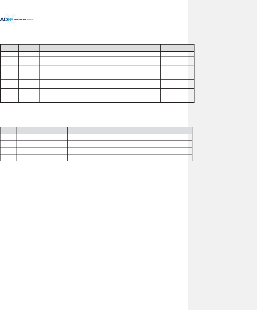
1.2.1 ADX-H-NMS-PKG Parts List
Table 1-1 ADX-H-NMS Parts List
Label
Quantity
Description
A
ADX-H-NMS-PKG (Network Management System Package)
1
ADX-H-NMS
1
ADX-H-PSU (AC to DC Supply)
1
ADX-H-CHC (Head End Channel Combiner)
B
1
AC Power Cord
C
1
RJ-45 Crossover Cable
D
1
Ground Cable
E
1
Documentation CD (User Manual, Quick Start Guide and Troubleshooting Guide)
F
1
Wall Anchor Bolt Set
G
28
SMA terminators
H
1
L-mounting Brace
A.
B. C. D. E. F.
G. H.
Advanced RF Technologies, Inc.
17
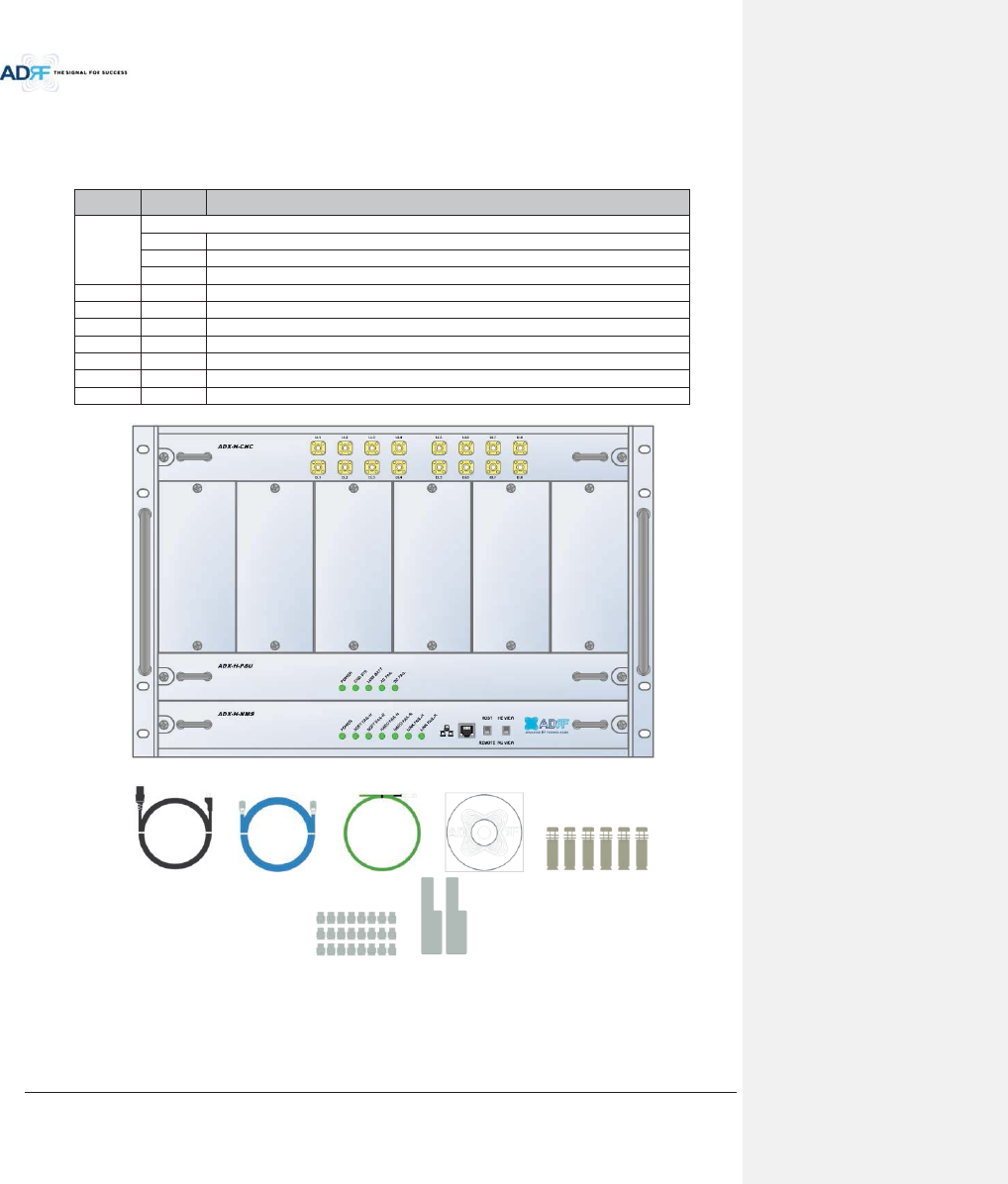
1.2.2 ADX-H-BCU Parts List
Table 1-2 ADX-H-BCU Parts List
Label
Quantity
Description
A
1
ADX-H-BCU (Band Combiner Unit)
B
6
N-Type terminators
C
2
NM to NM RF Jumper Cables (3ft)
D
1
Data/Power Cable
E
2
Chassis mounting brace
A.
B. C. D. E.
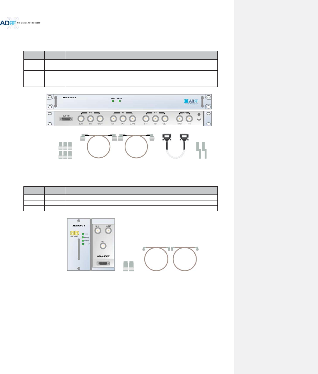
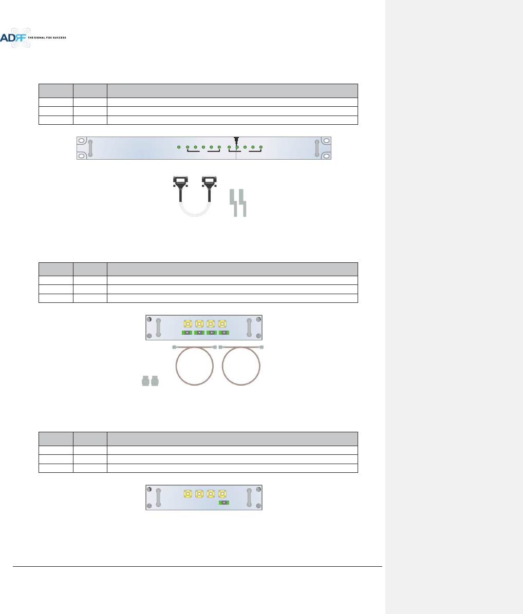
1.2.3 ADX-H-RFU Parts List
Table 1-3 ADX-H-RFU Parts List
Label
Quantity
Description
A
1
ADX-H-RFU (RF Unit)
B
2
N-Type Terminators
C
2
SMA Male RF Jumper Cables
A. B. C.
Advanced RF Technologies, Inc.
18
1.2.4 ADX-RACK-ODU Parts List
Table 1-4 ADX-RACK-ODU Parts List
Label
Quantity
Description
A
1
ADX-RACK-ODU
B
1
Data/Power Cable
C
1
Chassis Mounting Brace
A.
B. C.
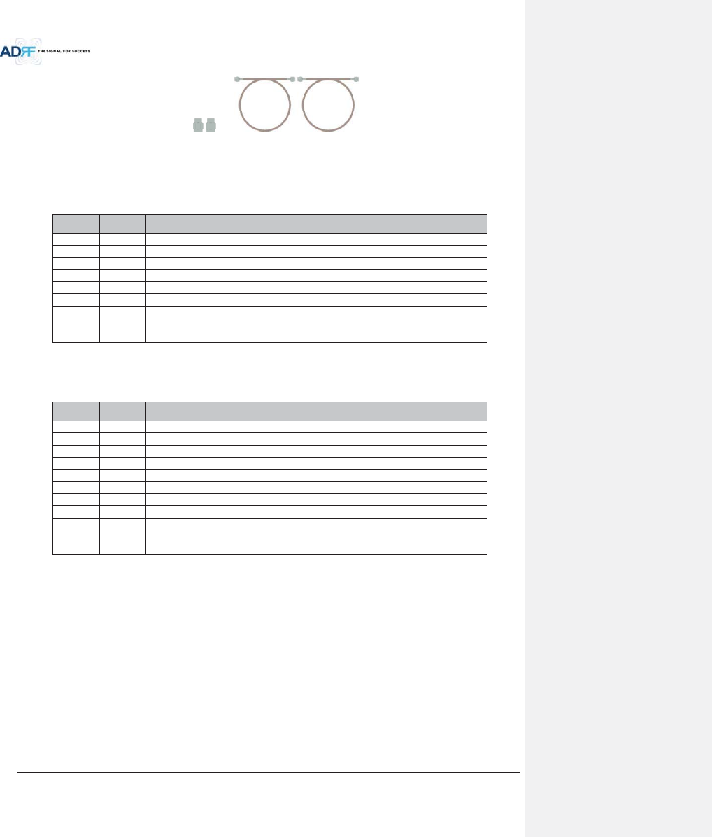
1.2.5 ADX-H-ODU4 Parts List
Table 1-5 ADX-H-ODU4 Parts List
Label
Quantity
Description
A
1
ADX-H-ODU4 (4-port Optical Unit)
B
2
SMA-M Terminators
C
2
SMA-M to SMA-M RF Jumper Cable (3ft)
A.
B. C.
1.2.6 ADX-H-ODU1 Parts List
Table 1-6 ADX-H-ODU1 Parts List
Label
Quantity
Description
A
1
ADX-H-ODU1 (1-port Optical Unit)
B
2
SMA-M Terminators
C
2
SMA-M to SMA-M RF Jumper Cable (3ft)
A.
LD FAIL LINK1 LINK2 LINK3 LINK4POWER
ADX-RACK-ODU
LD FAIL LINK1 LINK2 LINK3 LINK4
ODU2ODU1
VHF UL UL OUT VHF DL DL IN
LINK 4 LINK 3 LINK 2 LINK 1
ADX-H-ODU-4
VHF UL UL OUT VHF DL DL IN
LINK 1
ADX-H-ODU-1
Advanced RF Technologies, Inc.
19
B. C.
1.3 High Power Remote Unit Parts List
1.3.1 ADX-R-xxx43M (Main HRU) Parts List
Table 1-7 Main HRU Parts List
Label
Quantity
Description
A
1
ADX-R-xxx43M (Main HRU)
B
4
N type-M terminators
C
1
USB Cable
D
1
AC cable
E
1
Ground cable
F
4
Anchor Bolt
G
1
Manual CD
H
1
Install guide
I
1
Wall mount template
1.3.2 ADX-R-xxx43M (Main HRU) Parts List
Table 1-8 Extended HRU Parts List
Label
Quantity
Description
A
1
ADX-R-xxx43E (Extended HRU)
B
4
N type-M terminators
C
2
RF cable 6ft
D
1
USB cable
E
1
Crossover Ethernet cable 6ft
F
1
AC cable
G
1
Ground cable
H
4
Anchor Bolt
I
1
Manual CD
J
1
Install guide
K
1
Wall mount template
Advanced RF Technologies, Inc.
20
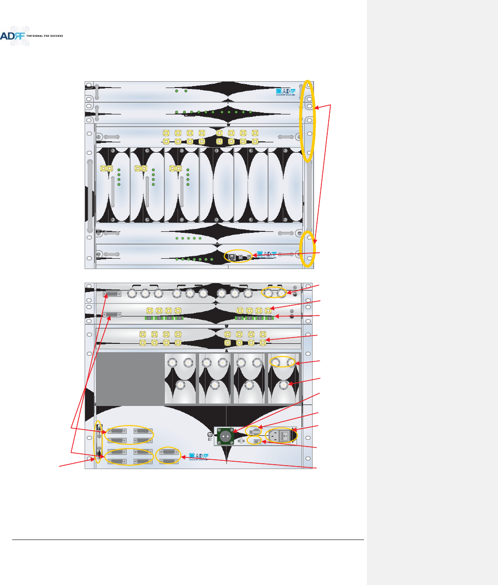
1.4 ADX DAS Quick View
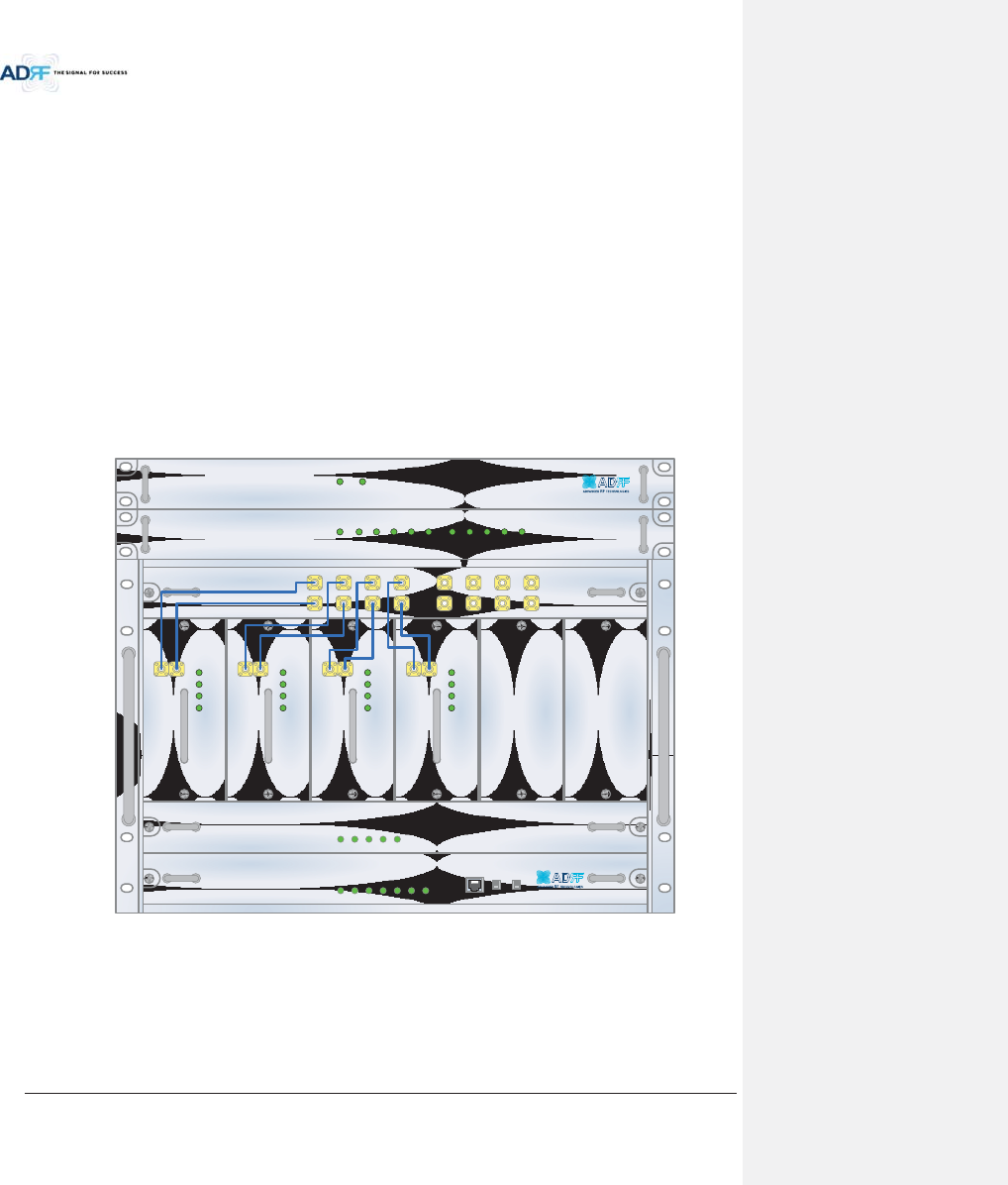
1.4.1 HE Quick View
1.4.2
ADX-H-NMS
POWER
SOFT FAIL-H
SOFT FAIL-R
HARD FAIL-H
HARD FAIL-R
LINK FAIL-H
LINK FAIL-R
HOST HE VIEW
REMOTE RU VIEW
DL OUTUL IN
HARD FAIL
DL SIG LOW
SOFT FAIL
POWER
ADX-H-RFU-P
DL OUTUL IN
HARD FAIL
DL SIG LOW
SOFT FAIL
POWER
ADX-H-RFU-7
ADX-H-CHC
UL1 UL2 UL3 UL4
DL1 DL2 DL3 DL4
UL5 UL6 UL7 UL8
DL5 DL6 DL7 DL8
ADX-H-PSU
POWER
CHG STS
LOW BATT
AC FAIL
DC FAIL
LD FAIL LINK1 LINK2 LINK3 LINK4POWER
ADX-RACK-ODU
LD FAIL LINK1 LINK2 LINK3 LINK4
ODU2ODU1
DL OUTUL IN
HARD FAIL
DL SIG LOW
SOFT FAIL
POWER
ADX-H-RFU-A
SOFT FAILPOWER
ADX-H-BCU-X
VHF UL 2 UL OUT 2 VHF DL 2 DL IN 2
LINK 8 LINK 7 LINK 6 LINK 5
VHF UL 1 UL OUT 1 VHF DL 1 DL IN 1
LINK 4 LINK 3 LINK 2 LINK 1
OPT
DL IN UL OUT
DPX
ADX-H-RFU-P
DL IN UL OUT
DPX
ADX-H-RFU-7
DL IN UL OUT
DPX
ADX-H-RFU-C
DL IN UL OUT
DPX
ADX-H-RFU-A
UL5UL6UL7UL8
DL5DL6DL7DL8
UL1UL2UL3UL4
DL1DL2DL3DL4
OPT 1 OPT 2
OPT 3 OPT 4
BAND COM 1 BAND COM 2
BAND COM 3 BAND COM 4
AUX_CH 1
AUX_CH 2
DL IN 3
BAND COM
CH3 CH2 CH1 SUM
DPX 3 UL OUT 3 DL IN 2 DPX 2 UL OUT 2 DL IN 1 DPX 1 UL OUT 1 DL OUT UL IN
BATTERY
INSTALL
BATTERY
BATTERY
AC SELECT OFF/ONAC IN
OFF
S/WOFF ON
24V 1A
19” rack mount
Holes
Host / Remote Switch,
HE view/RU view Switch
& RJ-45 port
Optic Ports
Battery Backup
Port
RFU Duplex Port
AC Input &
On/Off Switch
BCU Interface Ports
Band Combiner Unit
(BCU)
Optic Unit (ODU)
Channel Combiner
(CHC)
RF Channel Unit
(RFU)
Power Supply Unit
(PSU)
NMS Unit
Battery Backup
On/Off Switch
AC Input Voltage
Selection Switch
(110V/220V)
RFU Simplex
Port
ODU Interface Ports
AUX CH Interface
Ports
RF Ports connected to
ODU
RF Ports
connected to CHC
BCU Sum Port
Figure 1-1 ADX DAS HE Quick View
Ground terminal
Advanced RF Technologies, Inc.
21
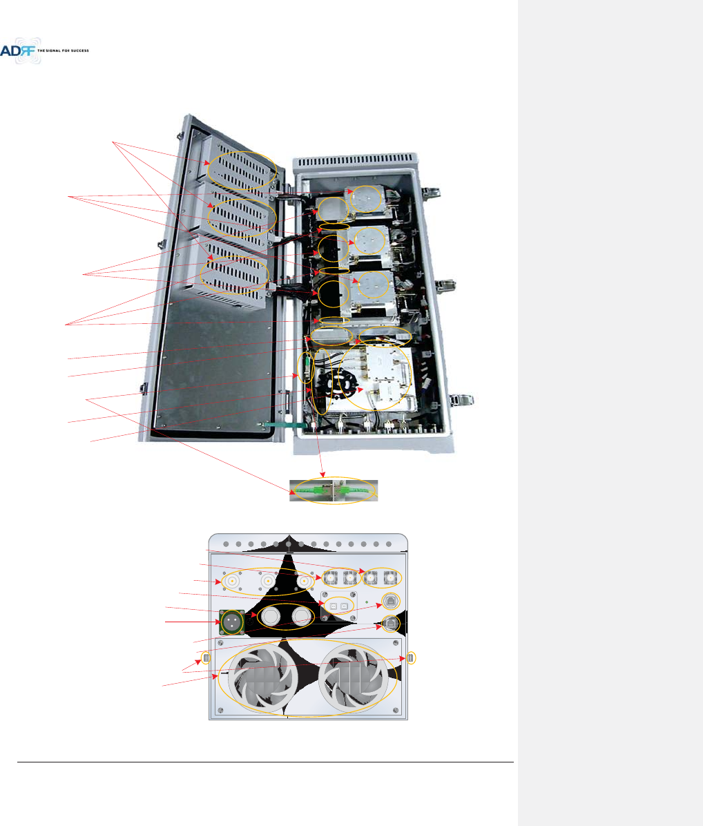
1.4.3 RU Quick View
Figure 1-2 ADX DAS HRU Quick View
Controller per band
RAU
Duplexer
HPA
ORU
RCU
Optic port
PSU
Splitter Unit
PCS_A_ SERVER AWS_A_ SERVER 700LTE_A_ SERVER
AC IN 110V
h
i
j
hGdGhjs
iGdGhju
jGdGmUn
OPTIC_A OPTIC_B
GUI_A GUI_B
DL_A UL_A DL_B UL_B
POWER
RS-485_A
RS-485_B
Server antenna port
AC port
Optic port
RF extension port for
additional band
Local GUI port
RS-485 port for
additional band
Fan unit
reserve port
RS-485 port for reserve
Ground terminal
Advanced RF Technologies, Inc.
22
1.5 Warnings and Hazards
Opening or tampering the ADX DAS will void all warranties.
WARRANTY
Actual separation distance is determined upon gain of antenna used.
Please maintain a minimum safe distance of at least 100
cm while operating near the donor and the server antennas.
Also, the donor antenna needs to be mounted outdoors on a permanent structure.
RF EXPOSURE & ANTENNA PLACEMENT Guidelines
Working with the ADX DAS
while in operation, may expose the technician to RF
electromagnetic fields that exceed FCC rules for human exposure. Visit the FCC website at
www.fcc.gov/oet/rfsafety
to learn more about the effects of exposure to RF electromagnetic
fields.
WARNING! EXPOSURE TO RF
Opening the ADX DAS
could result in electric shock and may cause
severe injury.
WARNING! ELECTRIC SHOCK
ָ֦ [Y1]:
ܹࢽ 50Æ100cm
2014/05/29
Advanced RF Technologies, Inc.
23
2. BLOCK DIAGRAM
Do not remove the protective covers on the fiber optic connectors until a connection is ready to be
made. Do not leave connectors uncovered when not connected.
The tip of the fiber optic connectors should not come into contact with any object or dust.
Refer to the cleaning procedure for information on the cleaning of the fiber tip.
Care of Fiber Optic Connectors
Fiber optic ports of the ADX DAS emit invisible laser radiation at the 1310, 1550nm wavelength
window.
To avoid eye injury never look directly into the optical ports, patch cords or optical cables. Do
not stare
into beam or view directly with optical instruments. Always assume optical output is on.
Only technicians familiar with fiber optic safety practices and procedures should perform optical
fiber connections and disconnections of the ADX DAS and the associat
ed cables.
The ADX DAS complies with 21 CFR 1040.10 and 1040.11 except for deviations pursuant to laser
notice No.50 (July26. 2001)@IEC 60825
-1, Amendment2 (Jan. 2001).
Laser Safety
NOTE: This equipment has been tested and found to comply with the limits for a Class A
digital device, pursuant to part 15 of the FCC Rules. These limits are designed to provide
reasonable protection against harmf
ul interference when the equipment is operated in a
commercial environment. This equipment generates, uses, and can radiate radio frequency
energy and, if not installed and used in accordance with the instruction manual, may cause
harmful interference to r
adio communications. Operation of this equipment in a residential area
is likely to cause harmful interference in which case the user will be required to correct the
interference at their own expense.
FCC Part 15 Class A
Advanced RF Technologies, Inc.
24
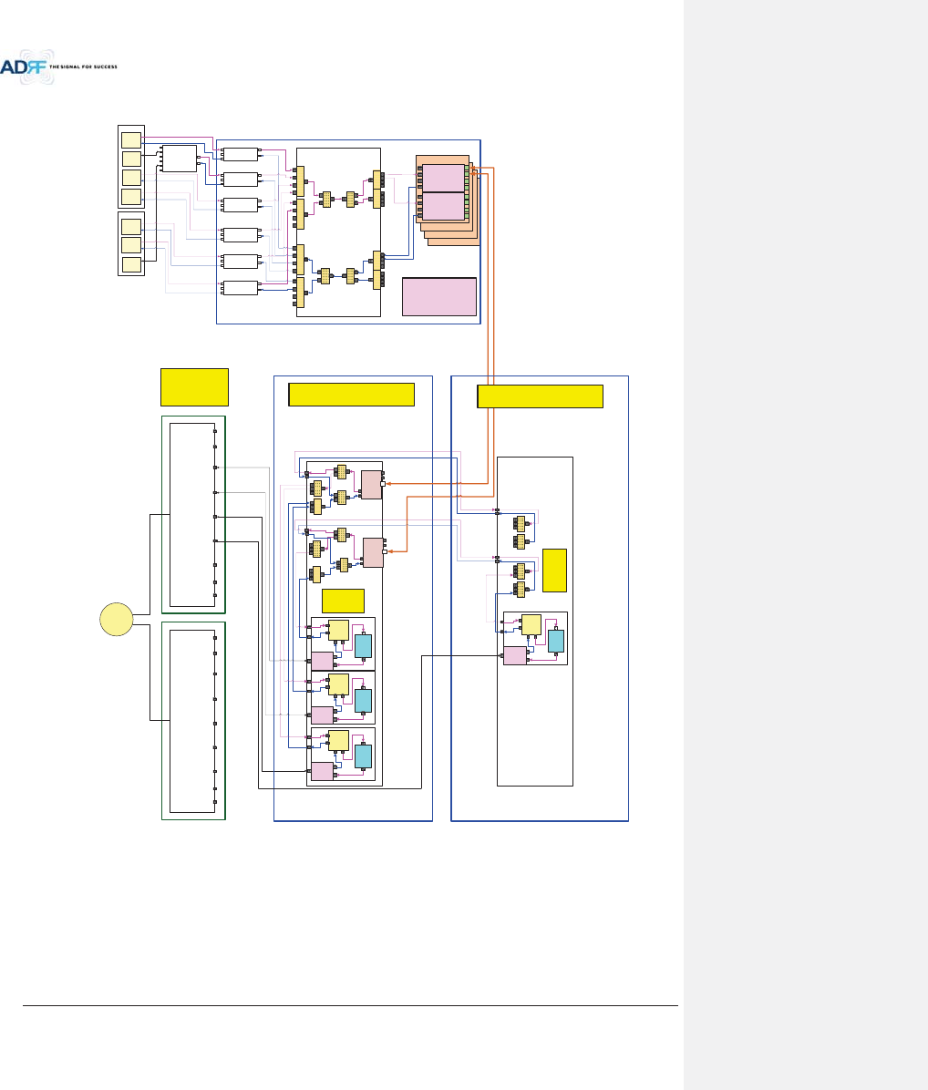
2.1 ADX DAS Block Diagram
Figure 2-1 ADX DAS Block Diagram (4BANDS)
vTo
vTo
jGj
AWS BTS
PCS BTS
CELL
BTS
700M
BTS
COM
PCS
CELL
AWS
700M
Reserved
WI-FI
tptvG
hu{
4:1
AWS
RFU
{
j
y
ks
|s
700M
RFU
{
j
y
ks
|s
SMR800
BTS
PCS BTS
PCS
Combiner
{
j
y ks
|s
{
j
y
SMR900
BTS
4:1
vTo
vTo
vk|JX
DL IN
V/UHF(136~512)
DL IN
(698~2690)
UL OUT
V/UHF(136~512)
UL OUT
(698~2690)
vk|JY
DL IN
V/UHF(136~512)
DL IN
(698~2690)
UL OUT
V/UHF(136~512)
UL OUT
(698~2690)
2:1 2:1
4:1 4:1 4:1 4:1
HPA
Duplexer
RAU
HPA
Duplexer
RAU
vy|
SMR800
RFU
{
j
y
ks
|s
SMR900
RFU
{
j
y
ks
|s
PCS
RFU
{
j
y
ks
|s
Cellular
RFU
{
j
y
ks
|s
4:1 4:1
2:1
2:1
2W
2W
BRS
SMR
wz|
4W 4W
HPA
Duplexer
RAU
Reserved
0$,1B+58
wz|
HPA
Duplexer
RAU
4W4W
#4 HRU
(CELL)
vy|
2W2W
4W 4W
#3 HRU
(700)
#2 HRU
(AWS)
#1 HRU
(PCS)
4W4W
(;7(16,21B+58
COM
PCS
CELL
AWS
700M
Reserved
WI-FI
BRS
SMR
Reserved
2SWLRQDO
&RPELQHU
+(
Advanced RF Technologies, Inc.
25
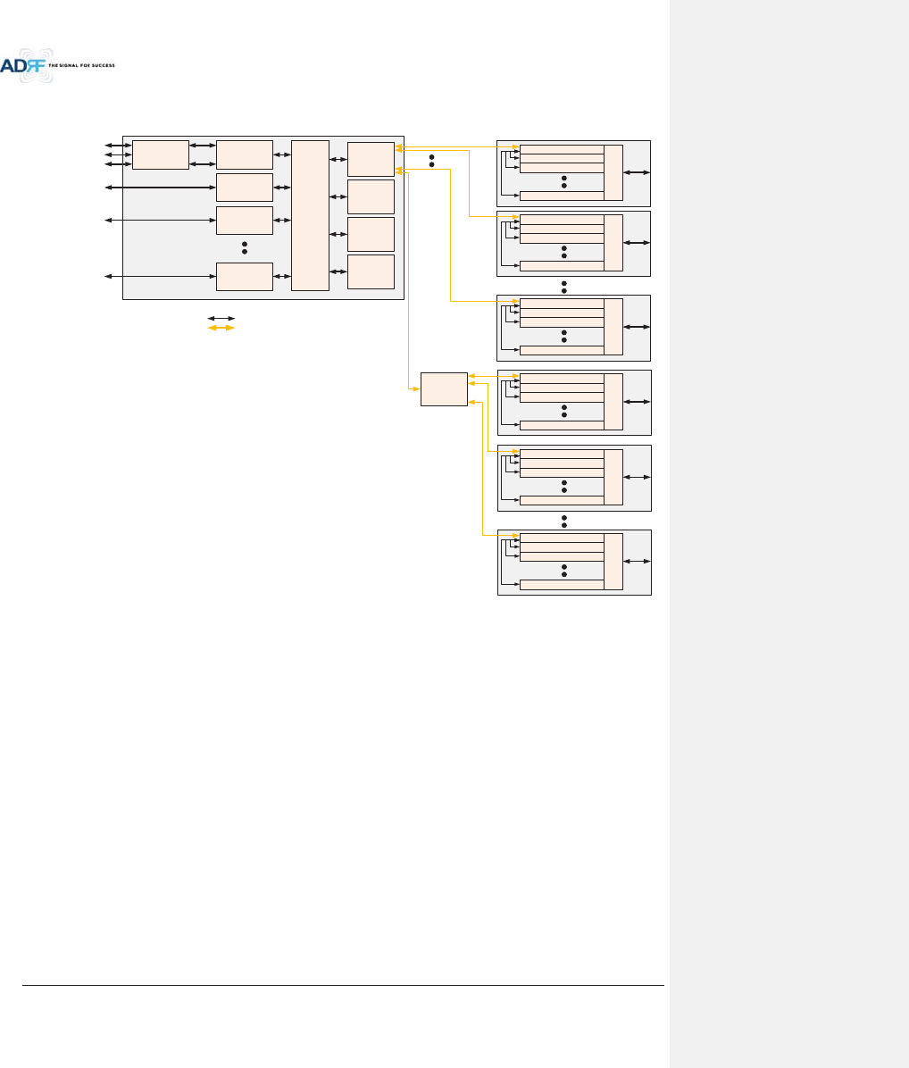
2.2 ADX DAS Topology
HE
(
Head End Unit
)
RU(Remote Unit)
Optic
RF
PCS RFU
(RF Interface Unit
with BTS or BDA)
Cellular RFU
(RF Interface Unit
with BTS or BDA)
AWS RFU
(RF Interface Unit
with BTS or BDA)
BCU(optional)
(Band Combiner Unit
with BTS or BDA)
Service Carrier #1
Service Carrier #2
Service Carrier #3
Service Carrier #1
Service Carrier #2
CHC-H
(HE Channel
Combiner)
700M RFU
(RF Interface Unit
with BTS or BDA)
Service Carrier #2
OPT-H
(RF to Optical)
OPT-H
(RF to Optical)
OPT-H
(RF to Optical)
OPT-H
(RF to Optical)
PCS Master RU
Combiner
Cellular Slave RU
AWS Slave RU
700M Slave RU
PCS Master RU
Combiner
Cellular Slave RU
AWS Slave RU
700M Slave RU
PCS Master RU
Combiner
Cellular Slave RU
AWS Slave RU
700M Slave RU
PCS Master RU
Combiner
Cellular Slave RU
AWS Slave RU
700M Slave RU
OEU
(Optic Expansion
Unit)
PCS Master RU
Combiner
Cellular Slave RU
AWS Slave RU
700M Slave RU
PCS Master RU
Combiner
Cellular Slave RU
AWS Slave RU
700M Slave RU
Figure 2-2 ADX DAS Topology

Advanced RF Technologies, Inc.
26
2.3 Configuration
2.3.1 Single band or multi-band configuration (1~3 bands)
Figure 2-3 ADX DAS 3bands Configuration
- HRU is composed of only Main HRU for 1~3 bands configuration
- In this case, Main HRU has single ORU.

Advanced RF Technologies, Inc.
27
2.3.2 Multi-band configuration (4~6 bands)
Figure 2-4 ADX DAS 4bands Configuration
- HRU is composed of Main HRU and Extended HRU for 4~6 bands
- In this case, Main HRU has single ORU.
- 2 RF cables needed between Main HRU and Extended HRU
- 1 communication cable needed between Main HRU and Extended HRU
2.4 ADX-DAS Scalability
Table 2-1 ADX-DAS Scalability
Unit Scalability Remarks
Supported band
700M, Cellular, AWS 1W/2W, PCS
1W/2W, SMR800/900, PS700
HE
RFU Up to 8
up to 6: card type
7
th
& 8
th
RFU: 19” rack type
NMS
1
Channel Combiner 1
Optic Unit Up to 4
Band Combiner Unit
Up to 4
To support multiple carriers
Power Supply Unit
(AC or DC)
1
Capable of supplying power to 8 RFUs, 4
BCUs, 4 ODU racks and NMS.
RU or HRU
RU or HRU
Up to 60
OEU Up to 4
PSU
(RU)
Adaptor type
1 per remote module
19” rack mount
1
Capable of supplying power to 8 Remote

Advanced RF Technologies, Inc.
28
(AC or DC)
Modules
Advanced RF Technologies, Inc.
29
3. ADX OVERVIEW
3.1 Head End
Head end components include:
ADX-H-NMS (Network Management System)
ADX-H-CHC (Head End Channel Combiner)
ADX-H-PSU (Head End Power Supply)
Up to [4] ADX-H-BCU (Band Combiner Unit)
Up to [8] ADX-H-RFU-x (RF Unit)
Up to [4] ADX-RACK-ODU (Optical Unit)
xSpecifications
- Size: 19.0 x 14.6 x 12.2 inches (482 x 370 x 311 mm)
- Weight: 83.7 lbs (38.0 Kg)@4 RFU, CHC-H, PSU and NMS
- Power Consumption: 52W@4 RFU, 1 ADX-H-ODU4 and NMS, 28W@1 RFU, 1 ADX-H-ODU4 and
NMS
- Power Input: 110VAC or -48VDC(optional)
- Supports the ADRF-BBU for external battery backup solution
ADX-H-NMS
POWER
SOFT FAIL-H
SOFT FAIL-R
HARD FAIL-H
HARD FAIL-R
LINK FAIL-H
LINK FAIL-R
HOST HE VIEW
REMOTE RU VIEW
ADX-H-PSU
POWER
CHG STS
LOW BATT
AC FAIL
DC FAIL
DL OUTUL IN
HARD FAIL
DL SIG LOW
SOFT FAIL
POWER
ADX-H-RFU-P
DL OUTUL IN
HARD FAIL
DL SIG LOW
SOFT FAIL
POWER
ADX-H-RFU-7
DL OUTUL IN
HARD FAIL
DL SIG LOW
SOFT FAIL
POWER
ADX-H-RFU-C
DL OUTUL IN
HARD FAIL
DL SIG LOW
SOFT FAIL
POWER
ADX-H-RFU-A
ADX-H-CHC
UL1 UL2 UL3 UL4
DL1 DL2 DL3 DL4
UL5 UL6 UL7 UL8
DL5 DL6 DL7 DL8
LD FAIL5-8 LINK5 LINK6 LINK7 LINK8LD FAIL1-4 LINK1 LINK2 LINK3 LINK4POWER
ADX-H-RACK-ODU
SOFT FAILPOWER
ADX-H-BCU-P
Figure 3-1 Head End Front View
Advanced RF Technologies, Inc.
30
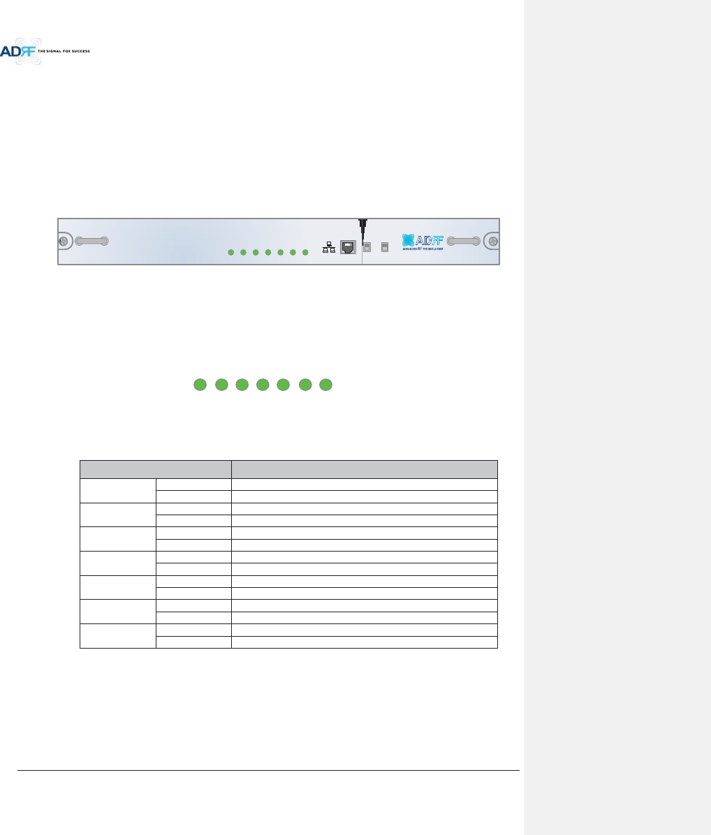
3.1.1 NMS (Network Management System)
xFunctions and features
- Supports SNMP v1, v2, and v3 (get, set & trap) and web-based GUI Interface.
- Monitors alarms and status
- Provides control interfaces with all subordinate modules
- Provides overall DAS structure via the auto tree update function
xSpec
- Size: 19.0 x 12.1 x 1.7 inches
-Weight: 5.5 lbs
ADX-H-NMS
POWER
SOFT FAIL-H
SOFT FAIL-R
HARD FAIL-H
HARD FAIL-R
LINK FAIL-H
LINK FAIL-R
HOST HE VIEW
REMOTE RU VIEW
Figure 3-2 ADX-H-NMS Front View
3.1.1.1 LEDs
NMS has LEDs on the front panel as shown in Figure 3-3.
POWER
SOFT-FAIL-H
SOFT-FAIL-R
HARD-FAIL-
H
HARD-FAIL-
R
LINK FAIL-H
LINK FAIL-R
Figure 3-3 NMS LED
Table 3-1 NMS LED Specifications
ADX DAS-NMS Specifications
Power
Solid Green
NMS power is ON
OFF
NMS power is OFF
SOFT FAIL-H
Solid Yellow
HE Soft Fail alarm exists in the system
Solid Green
No HE Soft Fail alarms are present in the system
SOFT FAIL-R
Solid Yellow
RU Soft Fail alarm exists in the system
Solid Green
No HRU Soft Fail alarms are present in the system
HARD FAIL-H
Solid Red
HE Hard Fail alarm exists in the system
Solid Green
No HE Hard Fail alarms are present in the system
HARD FAIL-R
Solid Red
RU Hard Fail alarm exists in the system
Solid Green
No HRU Hard Fail alarms are present in the system
LINK FAIL-H
Solid Yellow
HE Link Fail alarm exists in the system
Solid Green
No HE Link Fail alarms are present in the system
LINK FAIL-R
Solid Yellow
RU Link Fail alarm exists in the system
Solid Green
No HRU Link Fail alarms are present in the system

Advanced RF Technologies, Inc.
31
3.1.1.2 Ethernet Port
The Ethernet port can be used to communicate directly with the ADX DAS using a RJ-45 crossover cable or can
also be used to connect the ADX DAS to an external modem box.
H
OS
THE VIE
W
REMOTE RU VIE
W
Figure 3-4 Ethernet Port
3.1.1.3 Host/Remote Switch
The Host/Remote Switch allows the user to switch the default Repeater IP, Subnet Mask, and Gateway of the
repeater to an alternative setup. These settings can be adjusted by logging into the ADX DAS in HOST mode and
configuring the settings under the Modem Box Setting section under the Install Page of NMS.
Once the settings are set, flipping the switch to the REMOTE position will reboot NMS module with the new
alternate settings. Please note that when the NMS is set to the REMOTE position, DHCP is disabled and the NMS
will not automatically assign an IP address to any device that connects directly to the NMS.
H
OS
T HE VIE
W
REMOTE RU VIE
W
Figure 3-5 Host/Remote Switch
xHost IP: 192.168.63.1 (Fixed IP, unable to modify this IP address)
xRemote IP: 192.168.63.5 (Default IP, but can be modified in Host mode)
3.1.1.4 HE View/RU View Switch
The HE View/RU View Switch allows the user to disable the periodic monitoring performed by the NMS. In the
HE view mode, the NMS monitors the status of all subordinate units connected to NMS but when switched to HRU
view the NMS does not monitor the subordinate units. HRU View mode will allow the user to go to a HRU and
monitor/control the HE. If the NMS is set to the HE View mode and tries to connect to a HRU to monitor the HE,
data collisions between the NMS and HRU may prevent the user from properly monitoring or configuring the HE
when at the RU.
H
OS
T HE VIE
W
REMOTE RU VIE
W
Figure 3-6 HE View/RU View Switch
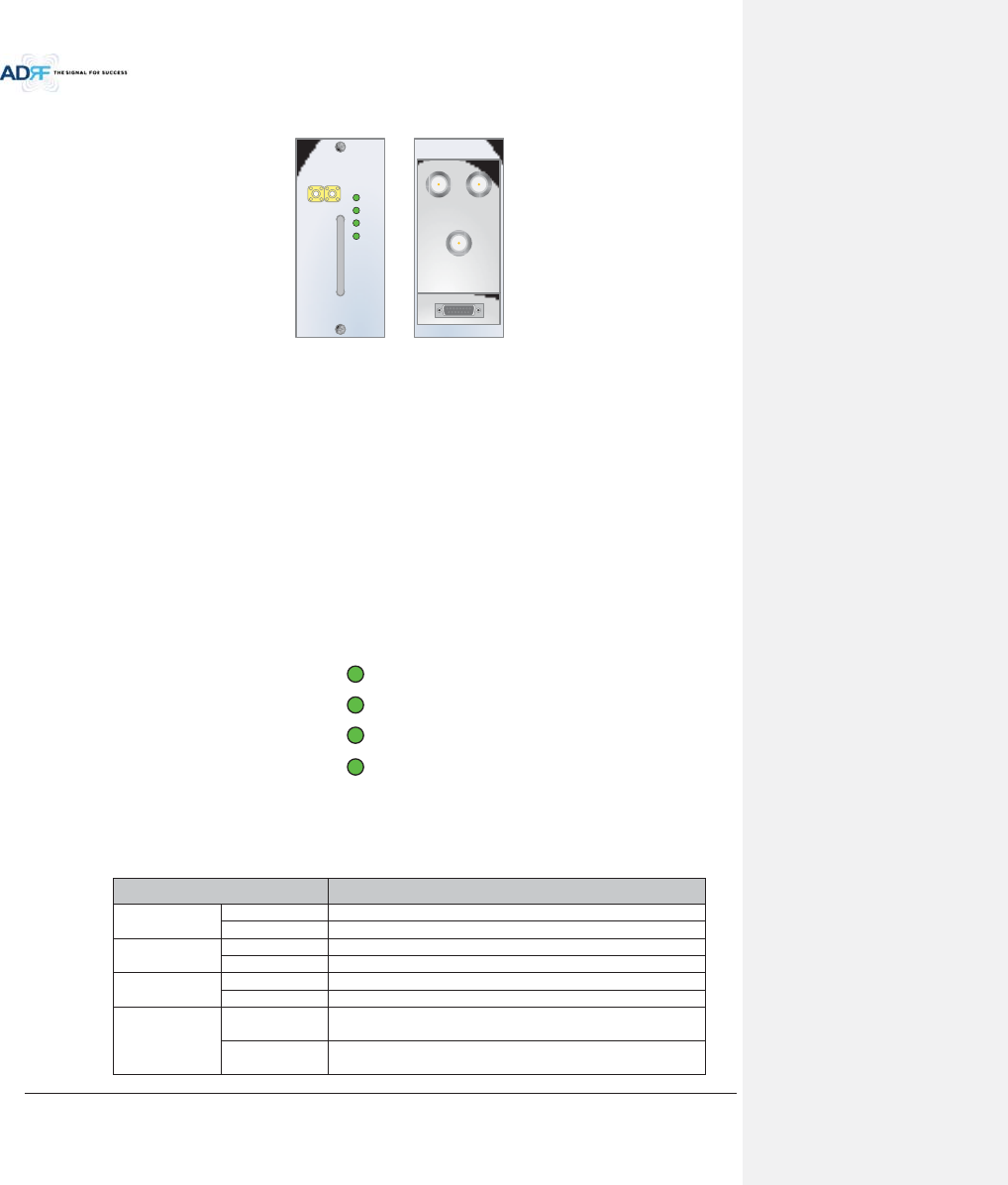
Advanced RF Technologies, Inc.
32
3.1.2 RFU (ADX-H-RFU-x)
DL OUTUL IN
HARD FAIL
DL SIG LOW
SOFT FAIL
POWER
ADX-H-RFU-P
ksGpu |sGv|{
kw
ADX-H-RFU-P
Figure 3-7 RFU Front & Rear View
xFunctions and features
-Provide RF interface with BTS
- Each RFU has independent gain control and filtering
- Modular type and hot swappable
- Supports duplex port or simplex TX & RX ports
- Easily support additional frequency bands by adding a single RFU
- Reduces complexity and overall equipment size
xSpecifications
- Size: 12.8 x 6.2 x 2.8 inches
-Weight: 7.3 lbs
3.1.2.1 LEDs
RFU has LEDs on the front panel as shown in Figure 3-8.
HARD FAIL
DL SIG LO
W
SOFT FAIL
POWER
Figure 3-8 RFU LED
Table 3-2 RFU LED Specifications
ADX DAS-Module Specifications
Power
Solid Green
Module power is ON.
OFF
Module power is OFF.
Soft Fail
Solid Yellow
Soft Fail alarm exists in the RFU.
Solid Green
No Soft Fail alarms are present in the RFU.
Hard Fail
Solid Red
Hard Fail alarm exists in the RFU.
Solid Green
No Hard Fail alarms are present in the RFU.
DL SIG LOW
Solid Yellow
When DL input signal level is lower than the defined threshold
level. (default threshold value: -5dBm)
Solid Green
When DL input signal level is upper than the defined threshold
level.
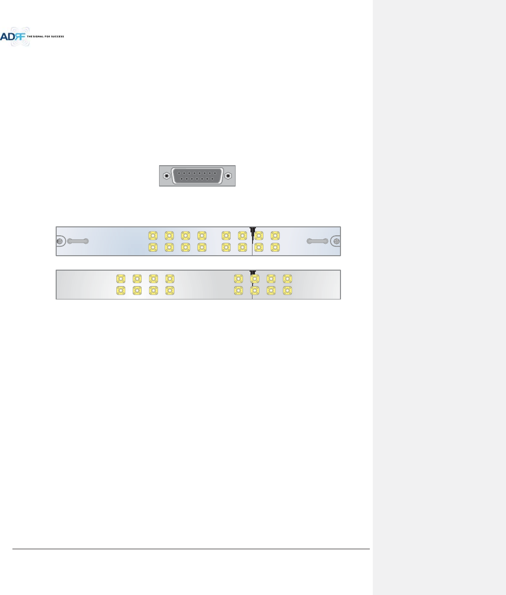
Advanced RF Technologies, Inc.
33
3.1.2.2 RF Ports
3.1.2.2.1 DL IN/UL OUT & DPX ports
DL IN/UL OUT & DPX Ports (refer to Figure 3-7) are located at the back of RFU and can be connected directly to
the BTS. The RFU can support incoming signal strength from 0 to 25dBm.
3.1.2.2.2 DL OUT/UL IN
DL OUT/UL IN Ports (refer to Figure 3-7) are located at the front of the RFU and connect directly to the HE
Channel Combiner (ADX-H-CHC).
3.1.2.3 Communication Port
The ADX-H-NMS monitors and controls the RFU via this port. DC Power is also provided to the RFU via this port.
Figure 3-9 Communication Port (RFU)
3.1.3 Channel Combiner (ADX-H-CHC)
ADX-H-CHC
UL1 UL2 UL3 UL4
DL1 DL2 DL3 DL4
UL5 UL6 UL7 UL8
DL5 DL6 DL7 DL8
UL5UL6UL7UL8
DL5DL6DL7DL8
UL1UL2UL3UL4
DL1DL2DL3DL4
Figure 3-10 ADX-H-CHC Front & Rear View
xFunctions & Features
- Combines DL signals received from each RFU and feeds the combined signals to the ADX-RACK-
ODU
- Combines UL signals received from each HRU and feeds the combined signal to the ADX-H-RFU
- Supports up to 8 RFUs and (4) ADX-RACK-ODU
xSpecifications
- Size: 16.9 x 12.9 x 1.7 inches
-Weight: 11.0 lbs
3.1.3.1 RF ports
3.1.3.1.1 RF ports at the front panel (DL 1 to DL 8, UL 1 to UL 8)
DL 1(to DL 8) & UL 1(to UL 8) RF ports are connected to DL OUT/UL IN Ports at the front panel of RFU.
xReceive the downlink signal from each RFU
xSplit the uplink signal received from ODU to each RFU
3.1.3.1.2 RF ports at the back panel (DL 1 to DL 8, UL 1 to UL 8)
DL 1(to DL 8) & UL 1(to UL 8) RF ports are connected to DL IN/UL OUT Ports at the back panel of ODU.
xTransfer the combined downlink signals to ODU
xReceive the uplink signal from ODU
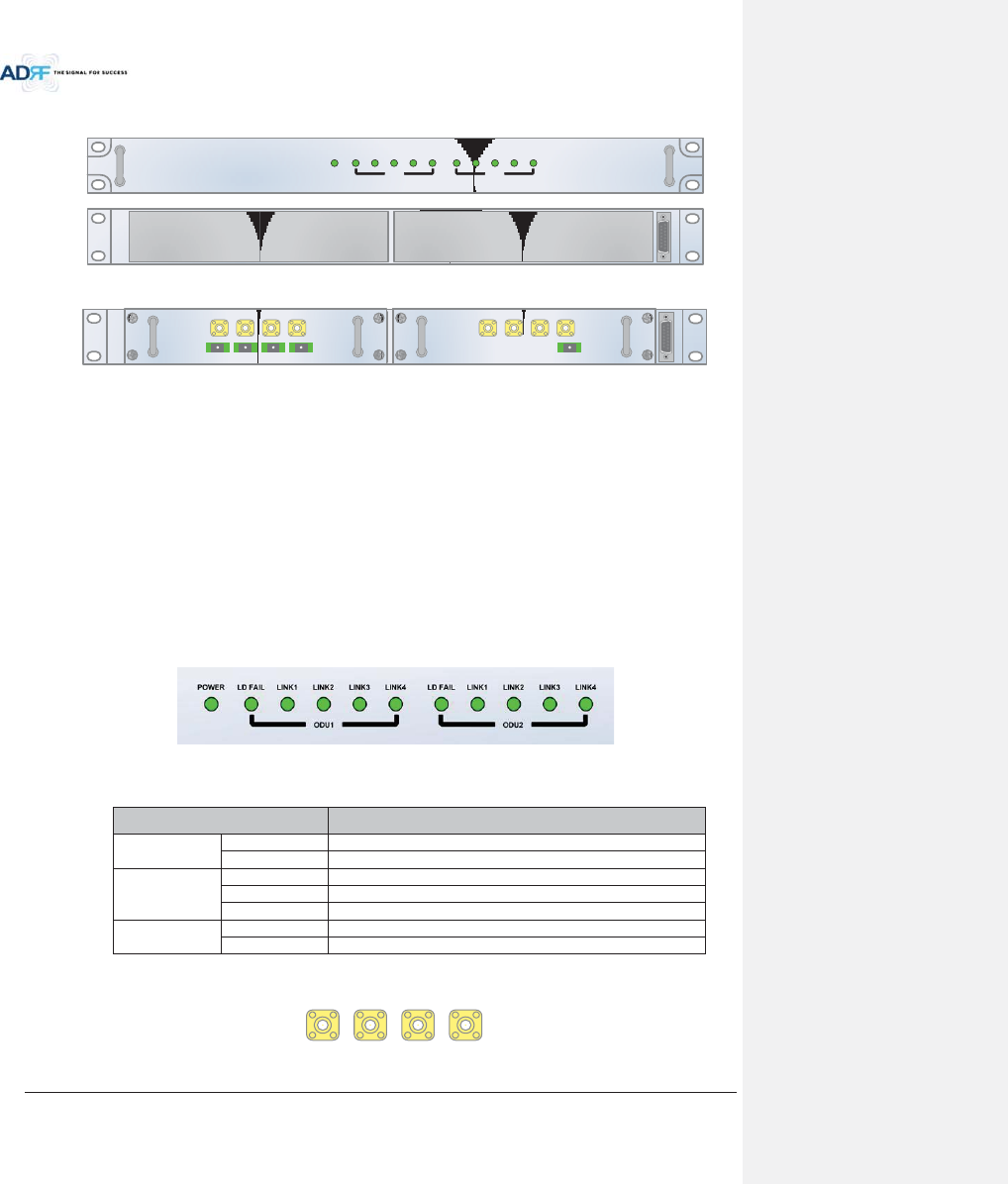
Advanced RF Technologies, Inc.
34
3.1.4 Optic Unit (ADX-RACK-ODU, ADX-H-ODU4/ADX-H-ODU1)
Figure 3-11 ADX-RACK-ODU Front & Rear view
Figure 3-12 ADX-H-ODU4 and ADX-H-ODU1 Installed in ADX-RACK-ODU
xFunctions & Features
- Converts signal from RF to optic and transports signals up to a maximum of 10Km (optical 5dBo
loss including optical connection loss).
- ADX-H-ODU4 can supports up to (4) Main HRUs and up to 5dBo optical loss.
- ADX-H-ODU1 can supports up to 10dBo optical loss.
- Minimizes the number of optic fiber cable need by transporting multi band signals over a single
strand of fiber using WDM technology.
xSpec
- Size: 19.0 x 12.9 x 1.7 inches (482 x 327 x 44 mm)
- Weight: 13.2 lbs (6.0 kg)
3.1.4.1 LEDs
The ADX-RACK-ODU has the following LEDs on the front panel as shown in Figure 3-13.
Figure 3-13 ADX-RACK-ODU LED
Table 3-3 ODU LED Specifications
ADX DAS-Module Specifications
Power
Solid Green
Module power is ON
OFF
Module power is OFF
LD FAIL
OFF
ODU is not installed
Solid Yellow
LD Fail alarm exists in the ODU
Solid Green
No LD Fail alarm is present in the ODU
LINK1 to LINK4
Solid Yellow
PD Fail alarm exists
Solid Green
No PD Fail alarm is present
3.1.4.2 RF Ports
VHF UL
1
UL
O
UT
1
VHF DL
1
DL IN
1
OPT
LD FAIL LINK1 LINK2 LINK3 LINK4POWER
ADX-RACK-ODU
LD FAIL LINK1 LINK2 LINK3 LINK4
ODU2ODU1
OPT
VHF UL UL OUT VHF DL DL IN
LINK 4 LINK 3 LINK 2 LINK 1
ADX-H-ODU-4
VHF UL UL OUT VHF DL DL IN
LINK 4 LINK 3 LINK 2 LINK 1
ADX-H-ODU-4
VHF UL UL OUT VHF DL DL IN
LINK 1
ADX-H-ODU-1
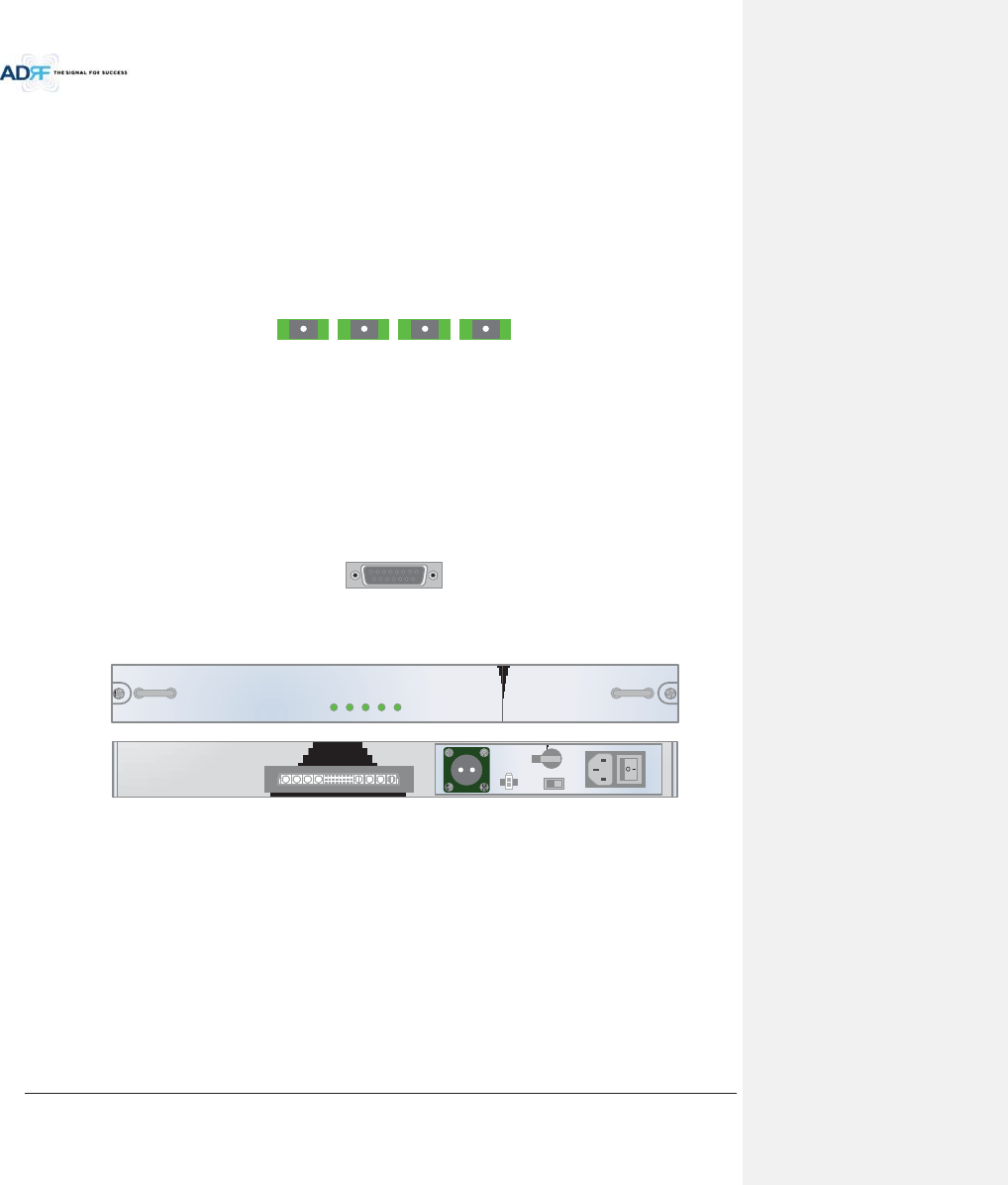
Advanced RF Technologies, Inc.
35
Figure 3-14 ODU RF Ports
3.1.4.2.1 DL IN/UL OUT
The combined downlink signal received from ADX-H-CHC is transferred to the DL IN 1(or 2) at the back of ODU.
The UL OUT port connects any of the ports on back of the ADX-H-CHC labeled UL 1 ~8.
3.1.4.2.2 VHF DL/VHF UL
VHF DL/UHF UL ports are used to support Public Safety in the VHF & UHF frequency bands. VHF/UHF signals
for Public Safety bypass the ADX-H-CHC and connect directly to the VHF DL/UHF UL ports of the ADX-H-ODU.
3.1.4.3 Optic Ports
LINK 4 LINK 3 LINK 2 LINK 1
Figure 3-15 ODU Optic Ports
The ADX-H-ODU4 has (4) optic ports and can support up to (4) Main HRU’s. Likewise, the ADX-H-ODU1 has (1)
optic ports and can support up to (1) Main HRU.
3.1.4.4 Communication Port
ADX-H-NMS monitors and controls the ADX-RACK-ODU via this port. DC power is provided from the ADX-H-
PSU to the ADX-RACK-ODU via this port.
O
PT
Figure 3-16 Communication Port (ODU)
3.1.5 Power Supply Unit (ADX-H-PSU)
ADX-H-PSU
POWER
CHG STS
LOW BATT
AC FAIL
DC FAIL
OFF
Figure 3-17 ADX-H-PSU Front & Rear View
xFunctions & Features
- Capable of supporting up to:
!(8) ADX-H-RFUs
!(4) ADX-H-BCU
!(4) ADX-H-ODU
!ADX-H-NMS
- Support the ADRF-BBU for an external battery backup solution
xSpecificaitons
- Size: 16.9 x 13.1 x 1.7 inches
- Weight: 7.7lbs
- Power Input: 110V or 220VAC, selectable by switch
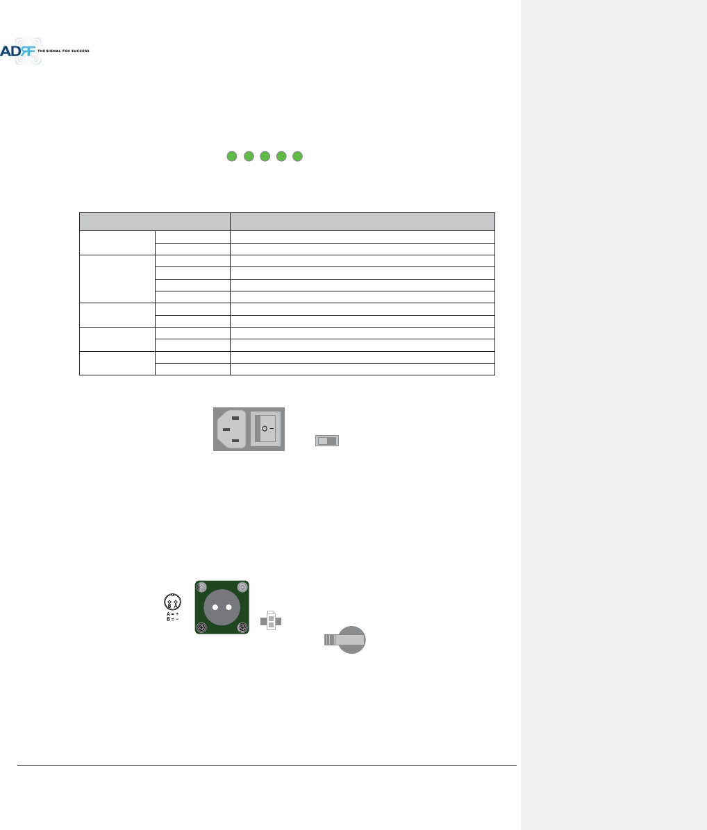
Advanced RF Technologies, Inc.
36
3.1.5.1 LEDs
ADX-H-PSU has the following LEDs on the front panel as shown in Figure 3-18.
POWER
CHG STS
LOW BAT
T
AC FAIL
DC FAIL
Figure 3-18 HE PSU LED
Table 3-4 HE PSU LED Specifications
ADX DAS-Module Specifications
Power
Solid Green
ADX-H-PSU power is ON
OFF
ADX-H-PSU power is OFF
CHG STS
Solid Yellow
No AC power is available and ADRF-BBU is being used
Blinking Green
PSU is charging the ADRF-BBU
Solid Green
ADRF-BBU is completely charged
OFF
Battery is not connected
LOW BATT
Solid Yellow
Low Battery alarm exist in the PSU
Solid Green
No Low Battery alarm is present in the PSU
AC FAIL
Solid Yellow
AC Fail alarm exists in the PSU
Solid Green
No AC Fail alarm is present in the PSU
DC FAIL
Solid Yellow
DC Fail alarm exists in the RFU
Solid Green
No DC Fail alarms is present in the PSU
3.1.5.2 AC Input On/Off Switch, AC Input Port and AC Input Selection Switch
ON/OFFAC IN
A
C SELEC
T
Figure 3-19 HE PSU AC Input On/Off Switch, AC Input Port and AC Input Selection Switch
The AC Power on/off switch is located at the back panel of HE PSU. The ADX-H-PSU can operate at 110V AC
and 220V AC. The user should verify that the AC input voltage switch is set to the correct voltage before powering
on the ADX-H-PSU.
3.1.5.3 Battery Backup Port, Battery Install Port and Battery Backup Switch
BATTERY
INSTALL
BATTERY
24V 1A
BATTERY
OFF
S/WOFF ON
Figure 3-20 Battery Backup Port, Battery Install Port and Battery Backup Switch
The Battery Switch can be used to provide power to the optional External Backup Battery (ADRF-BBU) (Figure
3-20).
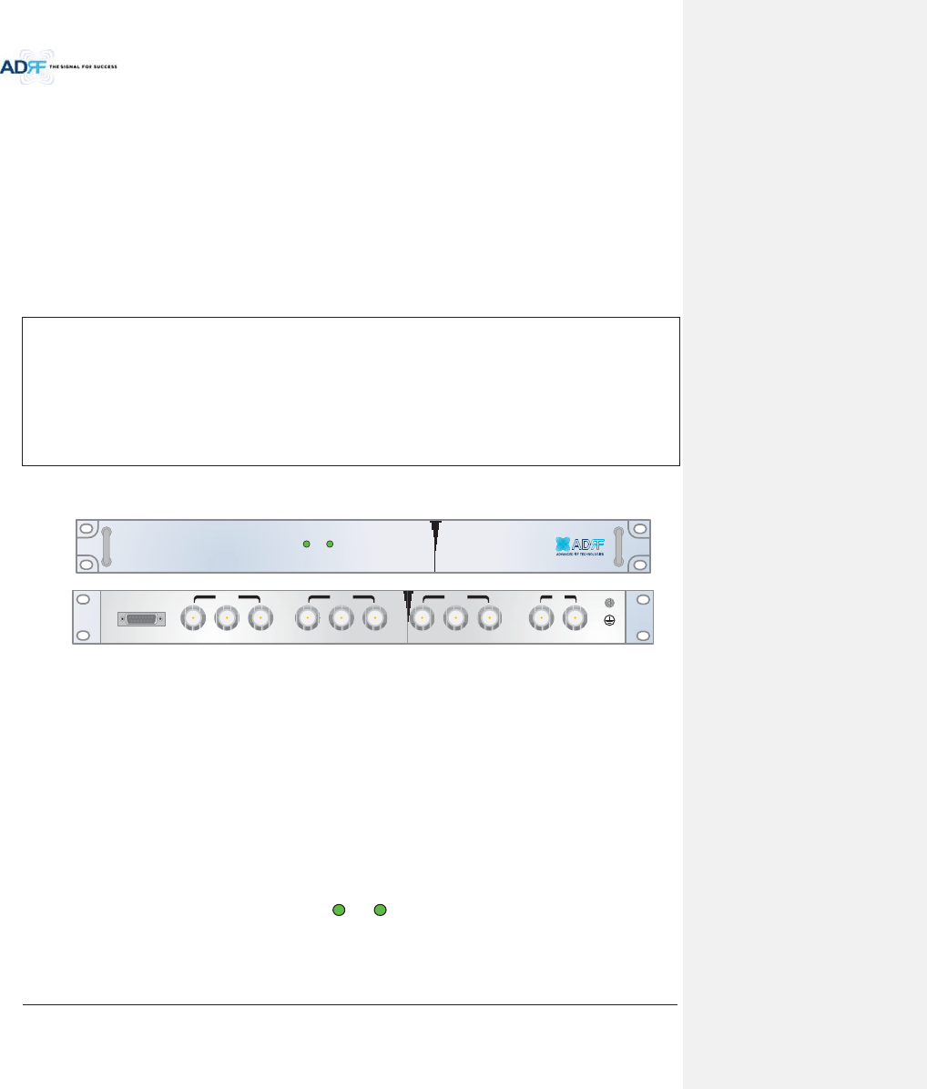
Advanced RF Technologies, Inc.
37
The ADX-H-PSU can be connected to an ADRF-BBU (ADRF Battery Backup Unit) which can provide power
during a power outage. If an ADRF-BBU is utilized, connect the ADRF-BBU to the ADX-H-PSU via the external
battery backup port as shown in Figure 3-20.
(WARNING: The circuit switch on the ADRF-BBU must be set to the OFF position before connecting the ADRF-
BBU to the ADX-H-PSU to prevent damage to the ADX-H-PSU or the ADRF-BBU and personal injury.)
Note: Please contact ADRF Technical Support for assistance if you are unfamiliar with the installation
procedure of our battery box.
The Battery Install port is used to let ADX-H-NMS know if an ADRF-BBU is connected to the ADX-H-PSU or not.
If an ADRF-BBU is connected without the cable connection to Battery Install port, the ADX-H-NMS will not detect
the ADRF-BBU.
The procedure for connecting HE PSU to BBU
BATT S/W OFF
Connect ADRF-
BBU to HE PSU Battery port and Battery Install port using HE battery
cable
BATT S/W ON
3.1.6 Optional Band Combiner Unit (ADX-H-BCU-x)
SOFT FAILPOWER
ADX-H-BCU-P
DL IN 3
BAND COM
CH3 CH2 CH1 SUM
DPX 3 UL OUT 3 DL IN 2 DPX 2 UL OUT 2 DL IN 1 DPX 1 UL OUT 1 DL OUT UL IN
Figure 3-21 ADX-H-BCU Front & Rear View
xFunctions & Features
-Combines and balances up to 3 carriers’ signals
-Easily supports multiple carriers’ signals by adding a single piece of equipment
- Reduces complexity and expansion costs to support multiple carriers’ signals in a single system
- Input range: +5 ~ +25dBm
xSpecifications
- Size: 19.0 x 12.9 x 1.7 inches
-Weight: 9.9 lbs
3.1.6.1 LEDs
The ADX-H-BCU has the following LEDs on the front panel as shown in Figure 3-22.
P
O
WER
SO
FT FAI
L
Figure 3-22 BCU LED
Table 3-5 BCU LED Specifications
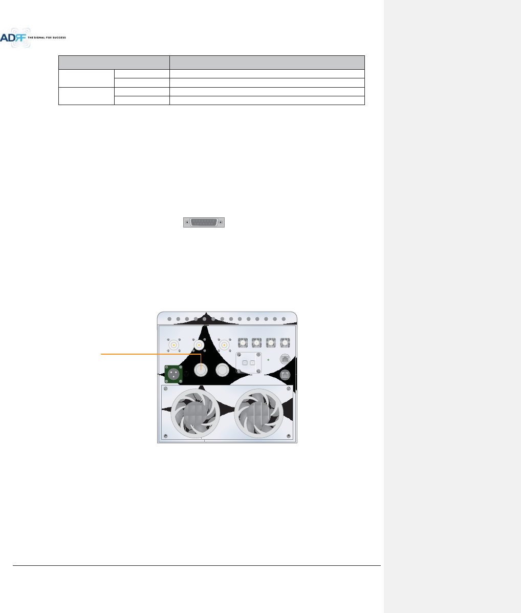
Advanced RF Technologies, Inc.
38
ADX DAS-Module Specifications
Power
Solid Green
Module power is ON
OFF
Module power is OFF
Soft Fail
Solid Yellow
Soft Fail alarm exist in the RFU
Solid Green
No Soft Fail alarms are present in the RFU
3.1.6.2 RF Ports
3.1.6.2.1 DL IN/UL OUT & DPX ports
DL IN/UL OUT & DPX Ports are located at the back of BCU and connect directly to a BTS.
3.1.6.2.2 DL OUT/UL IN
DL OUT/UL IN Ports are located on the back of ADX-H-BCU and connect directly to the ADX-H-RFU.
3.1.6.3 Communication Port
ADX-H-NMS monitors and controls the ADX-H-BCU via this port. DC Power is provided from ADX-H-PSU to the
ADX-H-BCU via this port.
BAND
CO
M
Figure 3-23 Communication Port (BCU)
3.2 HRU
- The High power remote unit is composed of a (1) Main HRU and up to (1) Extended HRU.
- Main HRU and Extended HRU use same enclosure.
Figure 3-24 ADX-HRU Single enclosure (bottom view)
3.2.1 Port
3.2.1.1 RF Port
3.2.1.1.1 Antenna server port (DIN type)
PCS_A_ SERVER AWS_A_ SERVER 700LTE_A_ SERVER
AC IN 110V
h
i
j
hGdGhjs
iGdGhju
jGdGmUn
OPTIC_A OPTIC_B
GUI_A GUI_B
DL_A UL_A DL_B UL_B
POWER
RS-485_A
RS-485_B
vG
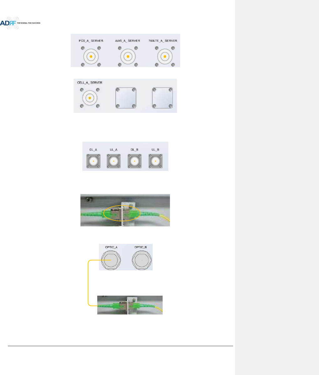
Advanced RF Technologies, Inc.
39
- Non-use port is masked with blank cover.
3.2.1.1.2 Extension port (N type)
- DL_A, UL_A : extension of additional band
- DL_B, UL_B : reserved port
3.2.1.2 Optic port
Figure 3-25 Inner Optic port connection
Figure 3-26 Optic connection
3.2.1.3 GUI, RS 485 port
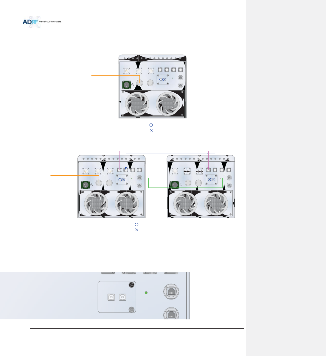
Advanced RF Technologies, Inc.
40
- GUI_A, RS 485_A is for additional band
- GUI_B, RS 485_B is for reserve
- GUI connectivity is along with optic line position (See the pictures below of various combinations)
Figure 3-27 ADX-HRU 3bands GUI connection (Single enclosure)
Figure 3-28 ADX-HRU 4bands GUI, RS 485 connection (2 enclosures)
3.2.2 LEDs
HRU has the following LEDs on the front panel as shown in Figure 3-29.
PCS_A_ SERVER AWS_A_ SERVER 700LTE_A_ SERVER
AC IN 110V
h
i
j
hGdGhjs
iGdGhju
jGdGmUn
OPTIC_A OPTIC_B
GUI_A GUI_B
DL_A UL_A DL_B UL_B
POWER
RS-485_A
RS-485_B
vG
|Gn|pG
|Gn|pG
PCS_A_ SERVER AWS_A_ SERVER 700LTE_A_ SERVER
AC IN 110V
h
i
j
hGdGhjs
iGdGhju
jGdGmUn
OPTIC_A OPTIC_B
GUI_A GUI_B
DL_A UL_A DL_B UL_B
POWER
CELL_A_ SERVER
AC IN 110V
h
i
j
hGdGhjs
iGdGhju
jGdGmUn
OPTIC_A OPTIC_B
GUI_A GUI_B
DL_A UL_A DL_B UL_B
POWER
RS-485_A
RS-485_B
RS-485_A
RS-485_B
vG
|Gn|pG
|Gn|pG
IN 110V
h
i
j
hGdGhjs
iGdGhju
jGdGmUn
OPTIC_A OPTIC_B
GUI_A GUI_B
POWER
RS-485_A
RS-485_B
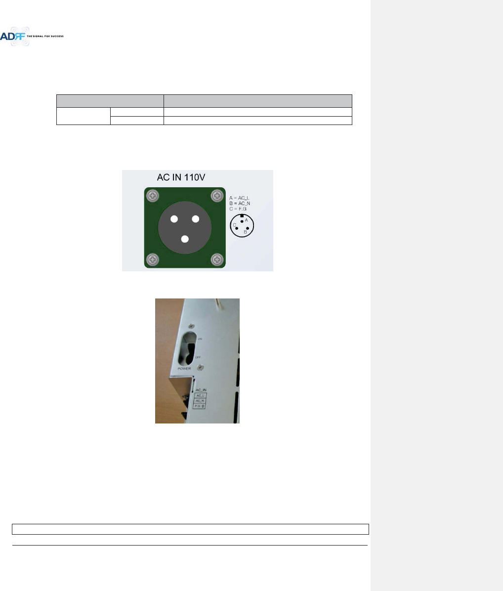
Advanced RF Technologies, Inc.
41
Figure 3-29 HRU LED
Table 3-6 Master HRU LED Specifications
ADX DAS-Module Specifications
Power
Solid Green
Module power is ON
OFF
Module power is OFF
3.2.3 AC On/Off Switch, AC Port
Figure 3-30 HRU AC Port
Figure 3-31 HRU AC Switch
The AC Power on/off switch is located on PSU in the enclosure of each ADX-HRU.
The ADX-HRU is operated at the only 110V AC.
The socket-outlet shall be installed near the equipment and shall be easily accessible
(WARNING: The AC switch must be set to OFF before cable connection to avoid equipment damage and
personal injury.)
(WARNING: To avoid damage, be sure 110V AC for operation of ADX-HRU.)
(CAUTION: DOUBLE POLE/NEUTRAL FUSING.)
The procedure for connecting HRU
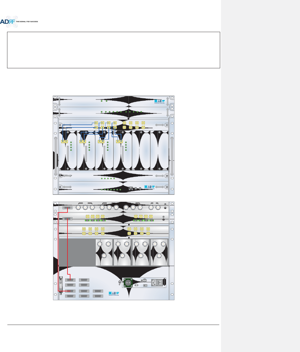
Advanced RF Technologies, Inc.
42
AC S/W OFF
AC cable connection
Optic connection
RF cable connection
RS 485 connection
AC S/W ON
4. CABLE CONNECTION
4.1 Head End Connection Diagrams
4.1.1 Front/Rear Head End Connection View with Optional BCU unit
ADX-H-NMS
POWER
SOFT FAIL-H
SOFT FAIL-R
HARD FAIL-H
HARD FAIL-R
LINK FAIL-H
LINK FAIL-R
HOST HE VIEW
REMOTE RU VIEW
ADX-H-PSU
POWER
CHG STS
LOW BATT
AC FAIL
DC FAIL
DL OUTUL IN
HARD FAIL
DL SIG LOW
SOFT FAIL
POWER
ADX-H-RFU-P
DL OUTUL IN
HARD FAIL
DL SIG LOW
SOFT FAIL
POWER
ADX-H-RFU-7
DL OUTUL IN
HARD FAIL
DL SIG LOW
SOFT FAIL
POWER
ADX-H-RFU-C
DL OUTUL IN
HARD FAIL
DL SIG LOW
SOFT FAIL
POWER
ADX-H-RFU-A
ADX-H-CHC
UL1 UL2 UL3 UL4
DL1 DL2 DL3 DL4
UL5 UL6 UL7 UL8
DL5 DL6 DL7 DL8
LD FAIL5-8 LINK5 LINK6 LINK7 LINK8LD FAIL1-4 LINK1 LINK2 LINK3 LINK4POWER
ADX-H-OPT
SOFT FAILPOWER
ADX-H-BCU-P
VHF UL 2 UL OUT 2 VHF DL 2 DL IN 2
LINK 8 LINK 7 LINK 6 LINK 5
VHF UL 1 UL OUT 1 VHF DL 1 DL IN 1
LINK 4 LINK 3 LINK 2 LINK 1
OPT
DL IN UL OUT
DPX
ADX-H-RFU-P
DL IN UL OUT
DPX
ADX-H-RFU-7
DL IN UL OUT
DPX
ADX-H-RFU-C
DL IN UL OUT
DPX
ADX-H-RFU-A
UL5UL6UL7UL8
DL5DL6DL7DL8
UL1UL2UL3UL4
DL1DL2DL3DL4
OPT 1 OPT 2
OPT 3 OPT 4
BAND COM 1 BAND COM 2
BAND COM 3 BAND COM 4
AUX_CH 1
AUX_CH 2
DL IN 3
BAND COM
CH3 CH2 CH1 SUM
DPX 3 UL OUT 3 DL IN 2 DPX 2 UL OUT 2 DL IN 1 DPX 1 UL OUT 1 DL OUT UL IN
BATTERY
INSTALL
BATTERY
BATTERY
AC SELECT OFF/ONAC IN
OFF
S/WOFF ON
24V 1A
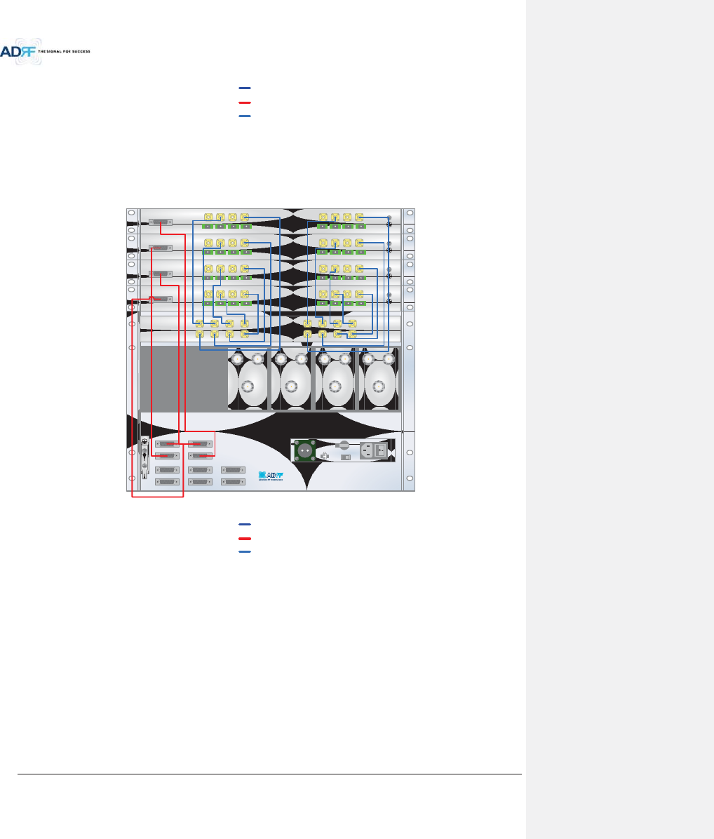
Advanced RF Technologies, Inc.
43
Figure 4-1 HE Cable connection (1 ADX-RACK-ODU +1 BCU)
4.1.2 Rear Head End Connection View with (4) ADX-RACK-ODU units
Figure 4-2 HE Cable connection (4 ADX-RACK-ODUs)
yz[_\
wGMGz
ym
DL IN UL OUT
DPX
ADX-H-RFU-P
DL IN UL OUT
DPX
ADX-H-RFU-7
DL IN UL OUT
DPX
ADX-H-RFU-C
DL IN UL OUT
DPX
ADX-H-RFU-A
UL5UL6UL7UL8
DL5DL6DL7DL8
UL1UL2UL3UL4
DL1DL2DL3DL4
OPT 1 OPT 2
OPT 3 OPT 4
BAND COM 1 BAND COM 2
BAND COM 3 BAND COM 4
AUX_CH 1
AUX_CH 2
VHF UL 2 UL OUT 2 VHF DL 2 DL IN 2
LINK 8 LINK 7 LINK 6 LINK 5
VHF UL 1 UL OUT 1 VHF DL 1 DL IN 1
LINK 4 LINK 3 LINK 2 LINK 1
OPT
VHF UL 2 UL OUT 2 VHF DL 2 DL IN 2
LINK 8 LINK 7 LINK 6 LINK 5
VHF UL 1 UL OUT 1 VHF DL 1 DL IN 1
LINK 4 LINK 3 LINK 2 LINK 1
OPT
VHF UL 2 UL OUT 2 VHF DL 2 DL IN 2
LINK 8 LINK 7 LINK 6 LINK 5
VHF UL 1 UL OUT 1 VHF DL 1 DL IN 1
LINK 4 LINK 3 LINK 2 LINK 1
OPT
VHF UL 2 UL OUT 2 VHF DL 2 DL IN 2
LINK 8 LINK 7 LINK 6 LINK 5
VHF UL 1 UL OUT 1 VHF DL 1 DL IN 1
LINK 4 LINK 3 LINK 2 LINK 1
OPT
OFF
BATTERY
INSTALL
BATTERY
BATTERY
AC SELECT OFF/ONAC IN
S/WOFF ON
24V 1A
yz[_\
wGMGz
ym
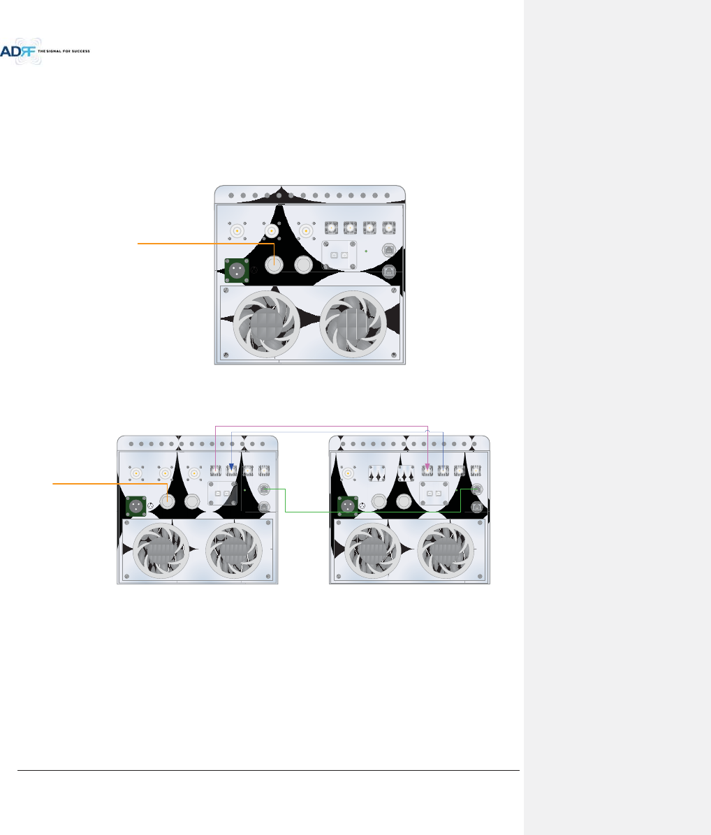
Advanced RF Technologies, Inc.
44
4.2 High Power Remote Unit Connection Diagrams
- Ethernet cable for RS 485 is crossover type
Figure 4-3 ADX-HRU 3bands connection (Single enclosure)
Figure 4-4 ADX-HRU 4bands connection (2 enclosures)
xWARNING! The RS-485 ports should NEVER be connected to the Enthernet port of laptop or Ethernet
Network Equipment. Doing so may cause serious damage to the Remote Modules or network equipments.
PCS_A_ SERVER AWS_A_ SERVER 700LTE_A_ SERVER
AC IN 110V
h
i
j
hGdGhjs
iGdGhju
jGdGmUn
OPTIC_A OPTIC_B
GUI_A GUI_B
DL_A UL_A DL_B UL_B
POWER
RS-485_A
RS-485_B
vG
PCS_A_ SERVER AWS_A_ SERVER 700LTE_A_ SERVER
AC IN 110V
h
i
j
hGdGhjs
iGdGhju
jGdGmUn
OPTIC_A OPTIC_B
GUI_A GUI_B
DL_A UL_A DL_B UL_B
POWER
CELL_A_ SERVER
AC IN 110V
h
i
j
hGdGhjs
iGdGhju
jGdGmUn
OPTIC_A OPTIC_B
GUI_A GUI_B
DL_A UL_A DL_B UL_B
POWER
RS-485_A
RS-485_B
RS-485_A
RS-485_B
vG

Advanced RF Technologies, Inc.
45
5. MOUNTING METHOD
5.1 Head End
5.1.1 Rack Mount
Figure 5-1 HE Rack Mount (Front & Rear view)
xExpandable up to 4 ADX-RACK-ODUs, 4 BCUs and 2 AUX CHs
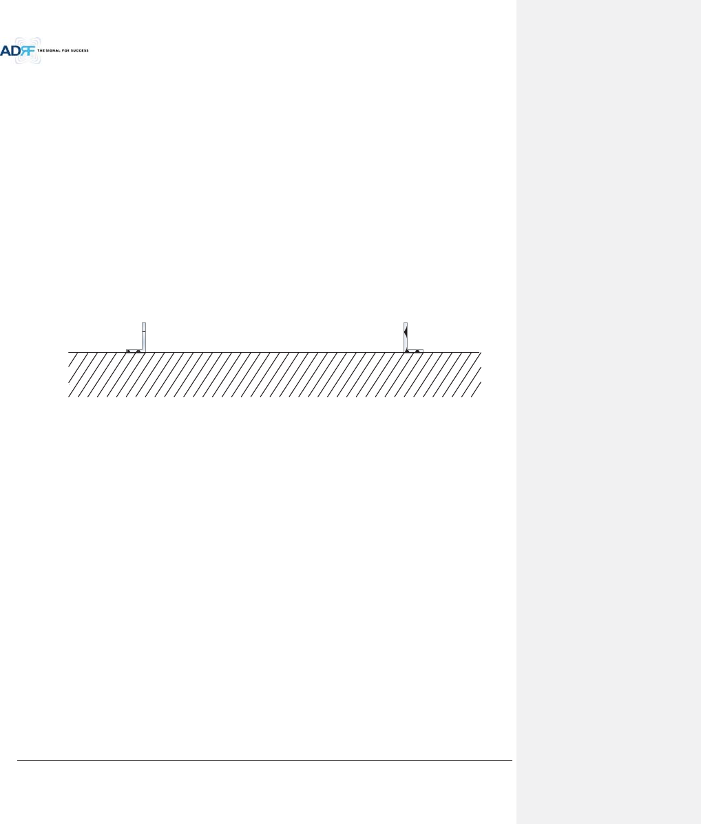
Advanced RF Technologies, Inc.
46
5.1.2 Wall Mount
Figure 5-2 HE Wall Mount (Top View)
xExpandable up to 3 units (ODU, BCU) or max 3U (132mm)
- ODU or BCU will be stacked up above basic 19” HE chassis which includes NMS, RFU, PSU and
CHC
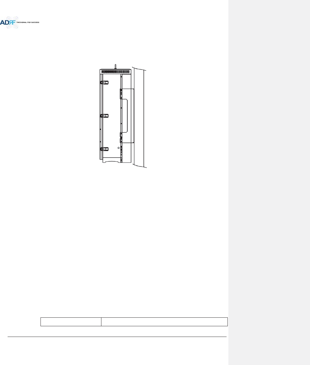
Advanced RF Technologies, Inc.
47
5.2 HRU
5.2.1 Wall Mount
ADX-HRU is support only wall mount.
Figure 5-3 HRU Wall Mount
6. INSTALLATION
6.1 Pre-Installation Inspection
Please follow these procedures before installing ADX HRU equipment:
oVerify the number of packages received against the packing list.
oCheck all packages for external damage; report any external damage to the shipping carrier. If
there is damage, a shipping agent should be present before you unpack and inspect the contents
because damage caused during transit is the responsibility of the shipping agent.
oOpen and check each package against the packing list. If any items are missing, contact ADRF
customer service.
oIf damage is discovered at the time of installation, contact the shipping agent.
oVerify the AC voltage with DVM (Volt meter) is 110V AC. Incorrect AC voltage can damage the
ADX equipment.
oThis power of this system shall be supplied through wiring installed in a normal building. If
powered directly from the mains distribution system, it shall be used additional protection, such
as overvoltage protection device.
oOver voltage category(OVC) & Pollution degree(PD)
Over voltage category (OVC)
OVC II

Advanced RF Technologies, Inc.
48
Pollution degree (PD)
PD2
6.2 ADX DAS Installation Procedure
6.2.1 HE Installation Procedure
CAUTION: ADX DAS HE should be installed inside building only.
6.2.1.1 Installing a ADX DAS HE in a rack
The ADX HE chassis mounts in a standard 19” (483mm) equipment rack. Allow clearance of 3” (76mm) at the
front and rear, and 2” (51mm) on both sides for air circulation. No top or bottom clearance is required.
xConsideration:
-Eight mounting holes are located on 4 corners of ADX HE to attach it to the 19” rack. The ADX HE
must be securely attached to a rack that can support the weight of the ADX.
xMount procedure
- The following steps should be followed while mounting the ADX HE
!Detach the wall mount bracket assembled located at the base of the ADX-HE chassis
!Verify that the HE and Mounting holes are in good condition
!Set the ADX DAS HE against the 19”rack and secure the unit with screws
!Verify that ADX HE is securely attached
!Connect the GND cable
!Connect the RF cable
!Connect the Power
!Connect the Optic cable
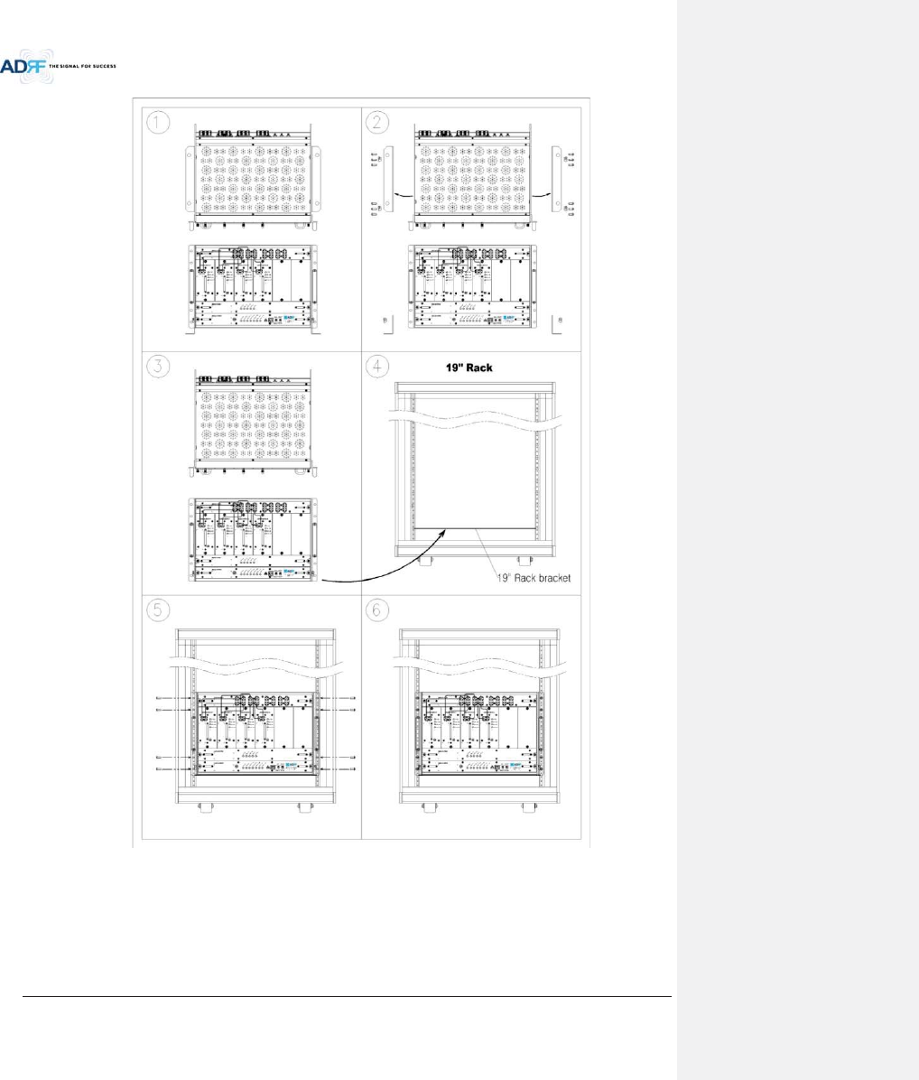
Advanced RF Technologies, Inc.
49
Figure 6-1 ADX HE 19” Rack Mount Instructions
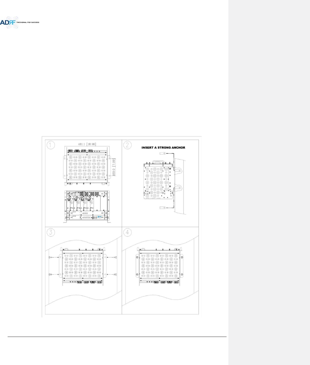
Advanced RF Technologies, Inc.
50
6.2.1.2 Wall mounting the ADX DAS HE
If the ADX HE chassis is being mounted to a wall, then allow clearance of at least 17” (430mm) on the top
(front side of HE) and 2” (51mm) on the bottom (rear side of HE) and 2” (51mm) on both sides and front for air
circulation.
xMount procedure
- The following steps should be followed when wall mounting the ADX HE
!Verify that the HE and Mounting hole are in good condition
!Place the ADX HE against the wall and mark of the mounting holes
!Drill holes(4holes, 18Żmm, 50mm depth) in the installation surface and insert the anchor bolts
!Bolt the ADX HE to the wall
!Make sure the ADX HE is securely attached
!Connect the GND cable
!Connect the RF cable
!Connect the Power
!Connect the Optic cable
Figure 6-2 ADX HE Wall Mount Instructions
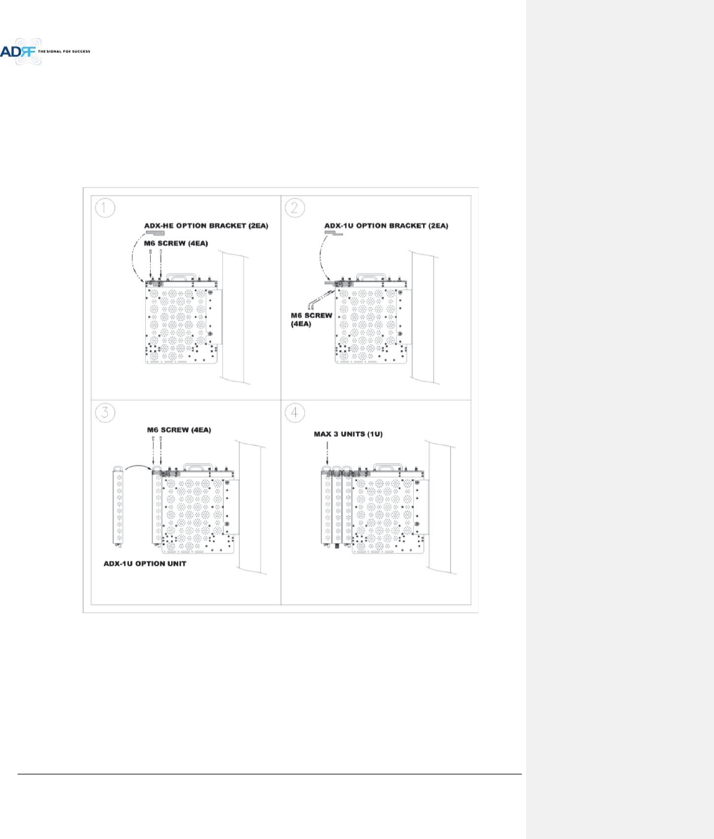
Advanced RF Technologies, Inc.
51
6.2.1.2.1 Installing added rack type modules into basic HE chassis
Additional modules such as the ADX-RACK-ODU and ADX-H-BCU can be mounted to the Chassis (ADX-H-CHA)
using the included mounting brackets that come with the add-on modules.
xA maximum of up to 3 addon modules (ODU, BCU) can be mounted to the chassis
- ODU or BCU will be stacked up above basic 19” HE chassis which includes NMS, RFU, PSU and
CHC
Figure 6-3 Wall Mount Instructions for ADX-HE added 1U Unit

Advanced RF Technologies, Inc.
52
6.2.2 RU Installation Procedure
Wall mounting the ADX HRU
xMount procedure
- The following steps should be followed while mounting the Remote Module
!Verify that the HRU and Mounting hole are in good condition
!Separate the wall mount bracket from the HRU
!Placed the wall mount bracket against the wall and mark off the mounting holes
!Drill holes(4holes, 18Żmm) in the installation surface then insert the enclosed anchor bolts
!Bolt the mounting bracket to the wall
!Install the HRU to the mounting bracket
!Fasten the HRU to the mounting bracket using the included screws
!Verify that the HRU is securely attached
!Connect the Antenna cable
!Connect the Power
!Connect the Optic cable (if applicable)
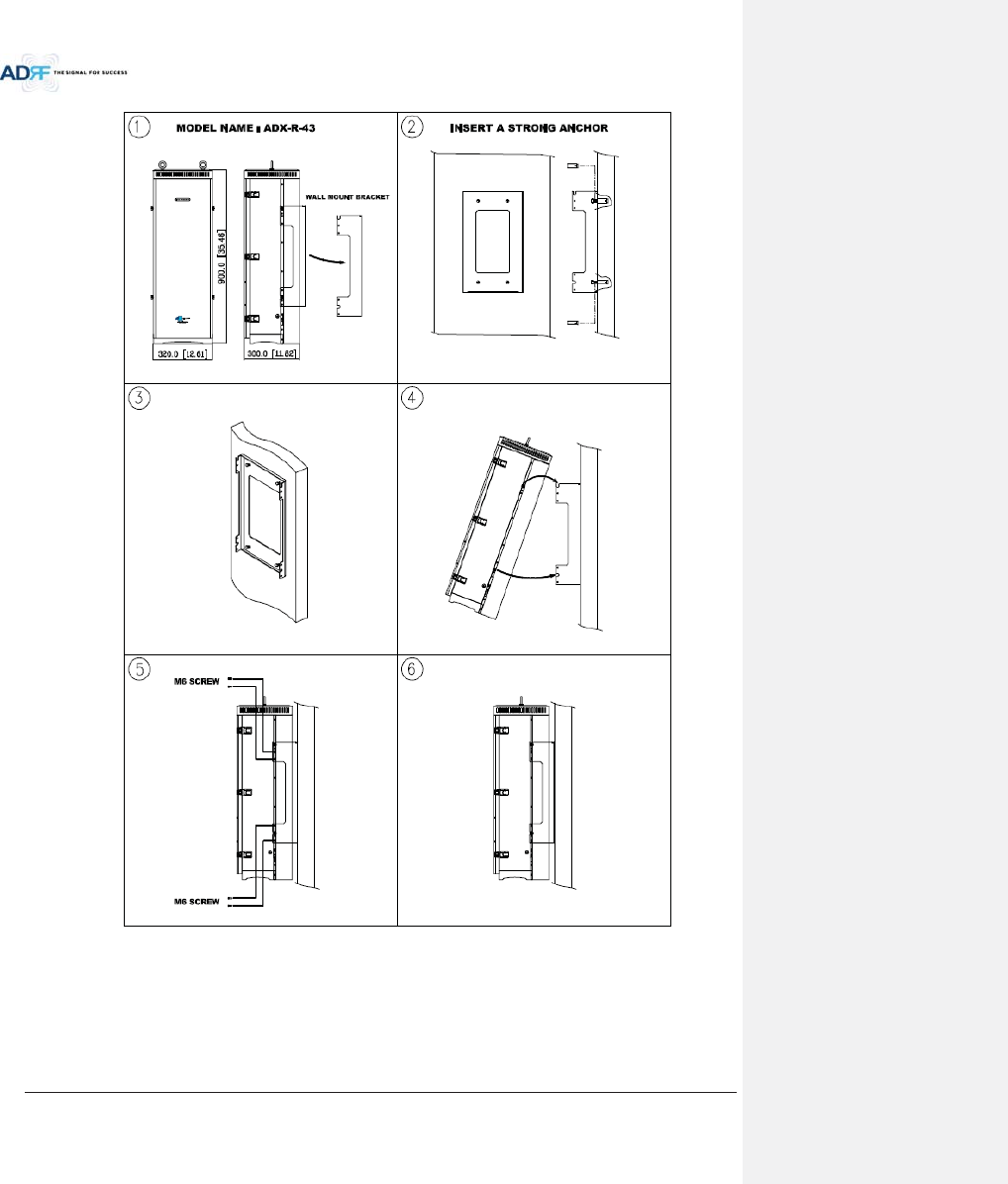
Advanced RF Technologies, Inc.
53
Figure 6-4 HRU Wall Mount Instructions
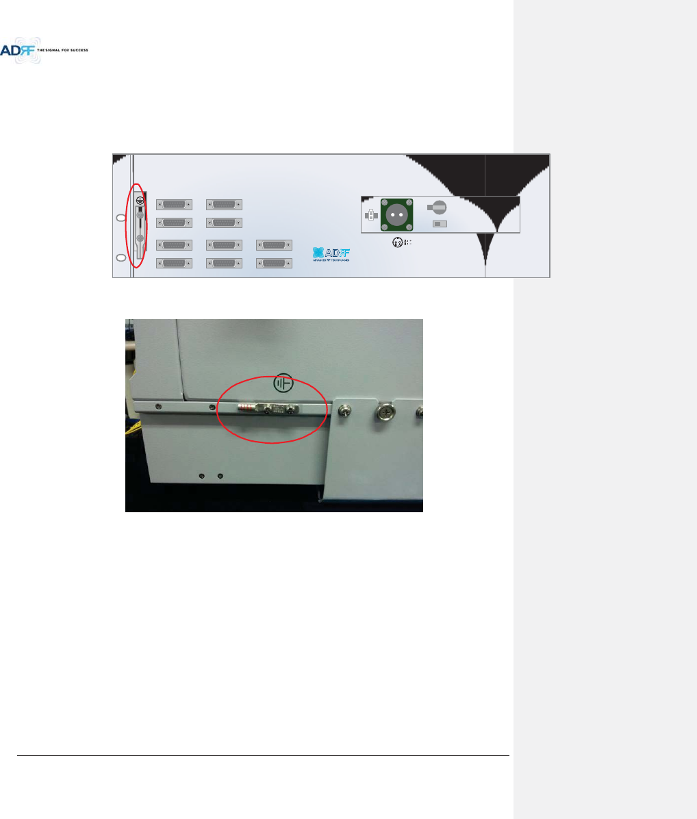
Advanced RF Technologies, Inc.
54
6.3 Grounding
A ground cable is included in the box. The grounding terminals are located at the rear of the ADX HE and RU.
The grounding cable should be properly connected before powering on the equipment.
Figure 6-5 Ground Cable Connection (HE rear side)
Figure 6-6 Ground Cable Connection (HRU dual side)
Round terminals located on the side of a 1.25mmŒ(16AWG)or more wires Using permanently connected to
earth.
OPT 1 OPT 2
OPT 3 OPT 4
BAND COM 1 BAND COM 2
BAND COM 3 BAND COM 4
AUX_CH 1
AUX_CH 2
BATTERY
INSTALL
BATTERY 24V BATT S/W
AC SELECT ON/OFF AC IN
OFF
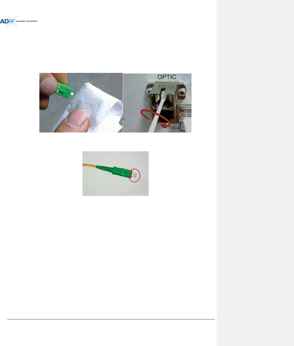
Advanced RF Technologies, Inc.
55
6.4 Optic Port Cleaning
xWe recommend cleaning optic connector using a dry optical cleaning swab or tissue in a dry environment as
needed. We recommend cleaning the optic connectors only if the expected optic loss is higher than the loss
reported in the Web-GUI by 1.5dBo. (Figure 6-7)
xWhen optic connector are not in use, the port should be covered with a protective dust cap. (Figure 6-8)
Figure 6-7 Optic Connector Cleaning (left) and Optic Port Cleaning (right)
Figure 6-8 SC/APC Optic Connector Dust Cap

Advanced RF Technologies, Inc.
56
7. COMMISSIONING
The commissioning process is composed of the following:
- Pre-Commissioning Check (refer to section 7.1)
- Optic Commissioning (Optic loss compensation) (refer to section 7.2.1)
- HE commissioning (refer to section 7.2.2)
- RU commissioning (refer to section 0)
- Commissioning verification (refer to section 0)
7.1 Pre-Commissioning Check
7.1.1 Verify cable connections
xBefore powering up units, check all RF cables, fiber cables, and power cables connections.
xAll power LEDs should be lit 1 minute after the components have been turned on.
xCheck whether LD & PD LEDs of HE ODU modules are solid GREEN. (PD LED will be lit green when connected to
a Master RU).
- If the PD LED for the link with a connection with to a HRU is OFF, then check the optic cable
connection.
- If the optic cable is good and the PD LED is not lit green, the try another optic port on the ADX-
RACK-ODU to see if the other port lights up green.
7.1.2 Connect to the Web-GUI
xConfirm that the NMS Host/Remote switch is set to the Host position
xConfirm that the HE View/RU View switch is set to the HE View position
xConnect the RJ-45 crossover cable from the Ethernet port of NMS to the Ethernet port of laptop
xLaunch a standard Internet browser like IE or Google Chrome and type the System Controller’s IP address
(192.168.63.1) into the addess bar
xOn the login screen use the following default login/password to gain access:
- Username: adrf
- Password: adrf
Figure 7-1 Login window
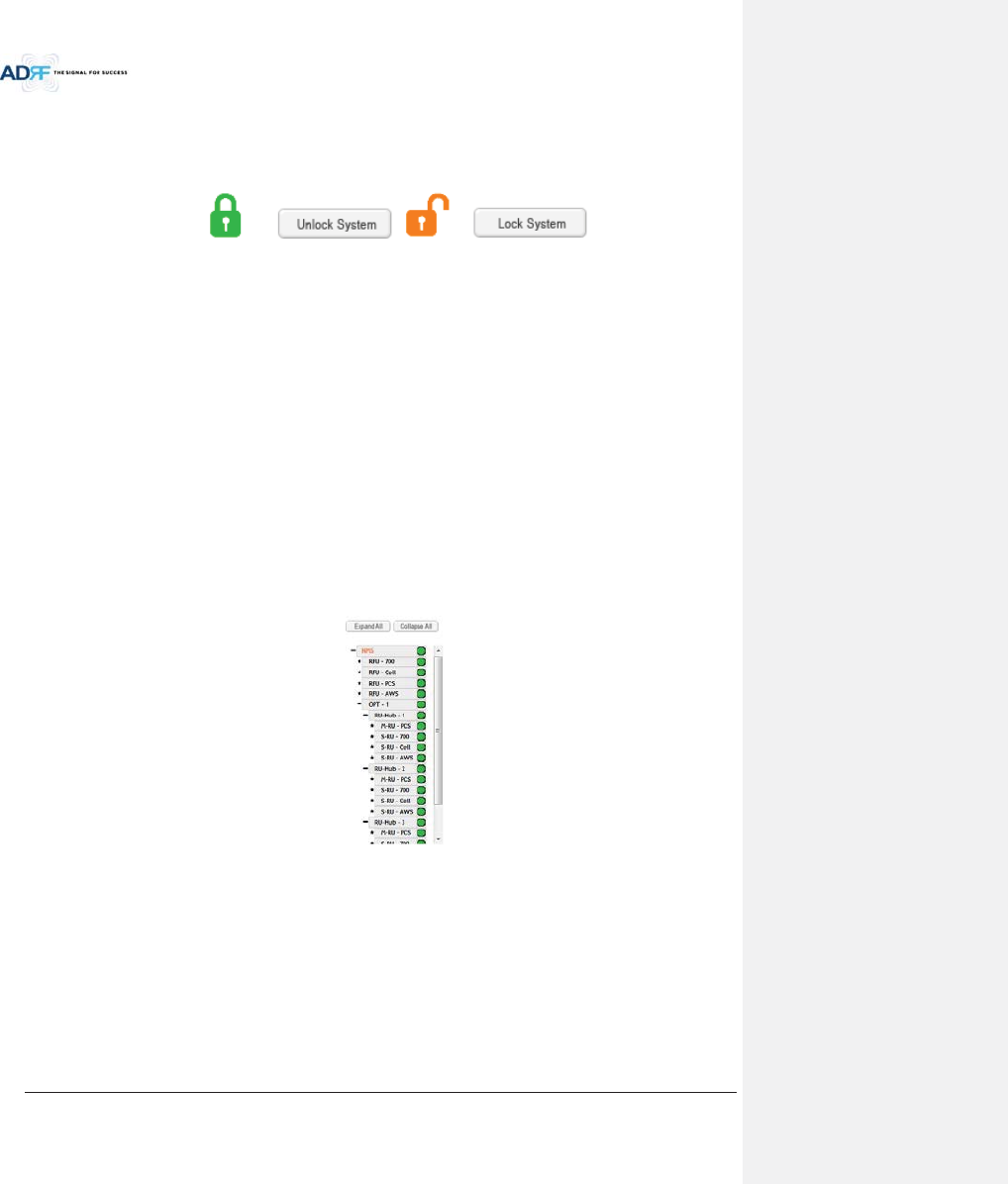
Advanced RF Technologies, Inc.
57
7.1.3 Check Navigation Tree Status
xCheck whether the status of navigation tree is Lock or Unlock.
xThe navigation tree should be in the “Unlock” state in when adding or removing active ADX components.
Figure 7-2 Navigation tree Lock/Unlock
When the system is locked:
Unable to detect any hardware that is added
Able to detect any link fails (communication errors between NMS and components)
System should be locked after final commissioning
When the system is unlocked:
Unable to perform BCU, RFU, or HRU commissioning
System is continually scanning for new hardware
7.1.4 Set Location Info, Installer Info and Date & Time
xGo to the Install page of NMS
xEnter Location & installer information
xSet current Date & Time
7.1.5 Verify Navigation Tree Links
xCheck whether all units connected to HE & HRU are being displayed in the navigation tree.
- Navigation tree is located on the left side of Web-GUI (Figure 7-3 )
Figure 7-3 Navigation tree
xCheck whether link fails exist. Link fails status can be seen on the front panel of NMS module via the Link Fail-
H and Link Fail-R LED lights.
- If LINK-H fail exists, power cycle the HE PSU and check if LINK-H fail is still present and repeat this
step up to 3 times or until the alarm clears. If LINK-H fail still exists after 3 power cycles, then
contact ADRF Technical support.
- If LINK-R fail exists, power cycle the ADX-H-ODU module which is connected to the Master HRU
with link fail and check to see if the LINK-R fail is still present and repeat this step up to 3 times or
until the alarm clears. If LINK-R fail still exists after 3 power cycles, contact ADRF Technical
support.

Advanced RF Technologies, Inc.
58
7.1.6 BOM Comparison & Check Band Configuration
xBOM comparison
- On the System information page in the System menu, the list of all components connected to the
ADX-H-NMS should match the ADX Navigation tree. This list can be used to verify BOM generated
by designer or installer for all active components. Please note that passive components such as
the ADX-H-CHC, ADX-R-CHC, ADX-H-PSU, and the ADX-R-4WS will not show up on this report.
xCheck Band Configuration
- Check whether the band configuration of ADX-H-RFU is identical to the band configuration of the
ADX HRU units. Any discrepancies will appear in the System Information report.
- Check to see if there are multiple remote modules with the same frequency bands within 1
remote unit. This information is displayed on the System Information page in the System menu
as notification message.
7.1.7 Lock current navigation tree
xIf there are no errors in the process of BOM Comparison & Check Band Configuration, then lock the Navigation
Tree by cliking on the “Lock System” button.
- After locking the Navigation Tree, link fail alarms should not appear. If link fail alarms are
present, please check the physical connection of the device with the link fail alarm.
-The system must first be placed in the “Unlock” state before adding any new devices. Newly
added devices will appear in the Navigation Tree when the page is refreshed. Once all new
hardware has been added to the Navigation Tree, the tree must be locked before commissioning
the system.
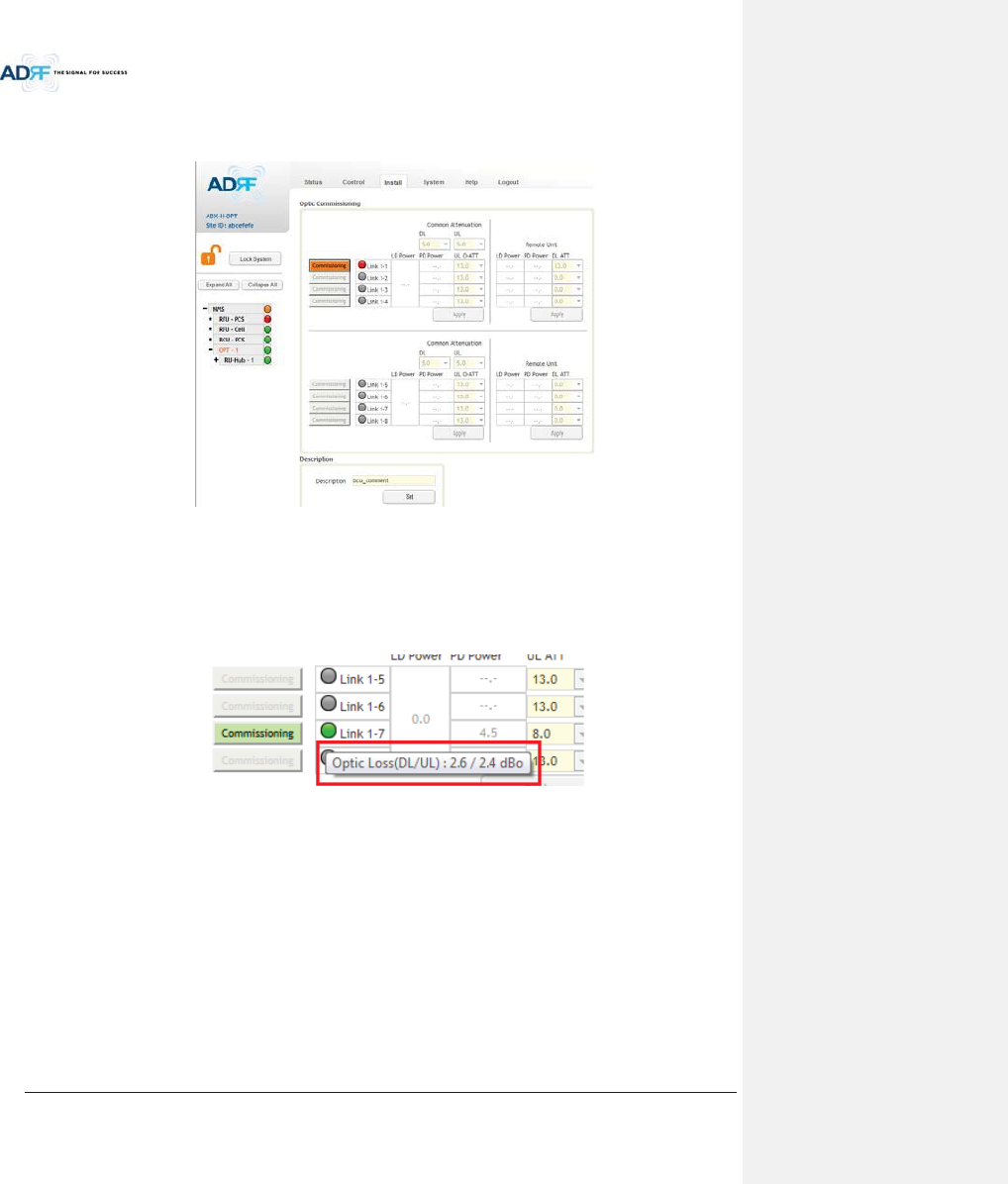
Advanced RF Technologies, Inc.
59
7.2 Commissioning
7.2.1 Optic Commissioning
Figure 7-4 ODU Install page
xNavigate to the Install page of ADX-H-ODU (Figure 7-4)
xCompare the values of measured optic loss (LD power – PD power) in the Web-GUI with the actual optic loss
which is typically measured at the time of installation of the fiber.
- The calculated optic loss is displayed when the mouse pointer is placed over the Status indicator
of each link
Figure 7-5 measured optic loss display
- If the difference between the measure optic loss and the calculated loss is larger than 1.5dBo,
then clean the optic connector and optic port using optical cleaning swab. (refer to section 6.4)
xThe following is the definiton of the Status indicator of each link:
- Green: Indicates that optic loss is less than 5dBo
- Orange: Indicates that optic loss is greater than 5dBo
- Gray: No Master HRU is connected to this link.
xThe following is the definition for the background color of the Commissioning button:
- Green: Indicates that no optic loss compensation is needed.
- Orange: Indicates that optic loss compensation is needed.
- Gray: No Master HRU is connected to this link.
7.2.1.1 How to compensate the optic loss

Advanced RF Technologies, Inc.
60
Optic loss compensation should be performed when the color of “Commissioning” button is orange. The
“Commissioning” button will turn orange when the difference between the compensated attenuation and the
actual compensated attenuation level is greater than 1.5 dB. Optic compensation can be performed by clicking the
orange “Commissioning” button.
xThe optic loss compensation for uplink and downlink are performed separately.
- The optic loss compensation for downlink will be performed based on the LD level of the ODU
and the PD level of the Master RU.
- The optic loss compensation for uplink will be performed based on the LD level of the Master
HRU and the PD level of the ODU.
xOptic loss compensation adjusts the attenuation based on Table 7-1 and the calculated optic loss (LD level-PD
Level).
- The calculated optic loss is displayed when a mouse is placed on the circle of each link. (Refer to
section 7.2.1.1)
- Based on the table below, when the calculated optic loss is 1dB, the attenuation will be set to
11dB.
- The attenuator for downlink optic loss compensation is located at the Master RU.
- The attenuators for uplink optic loss compensation are located at the ODU.
Table 7-1 Optic loss compensation table
Optic Loss (dBo) Compensated Attenuation (dB)
0
13
0.5
12
1
11
2
9
3
7
4
5
5
3
xExample: Let’s say that this ADX-H-ODU had previously been commissioned in a system where the optic loss
was 3 dBo. In the previous system, the correct amount of attenuation is 7dB. The ADX-H-ODU was moved to
another site and the new system has an optic loss of only 1dBo. At 1dBo of loss, the correct amount of
attenuation should be 11 dB. When this system powers on, optic commissioning will need to be performed
because the difference between the old attenuation level and the new attenuation level is 4dB which exceeds
the 1.5 dB threshold. Once optic commissioning is performed, it will set the attenaution level to 11 dB.

Advanced RF Technologies, Inc.
61
7.2.2 HE Commissioning
HE commissioning is composed of HE BCU and HE RFU commissioning. The HE BCU is an optional component
and should be used when WPSs’ signals are being used in the same frequency band.
7.2.2.1 Composite power
To perform HE commissioning, the user should calculate downlink composite input level and add the proper
amount of breath room required for rise in traffic.
xInformation that is needed to calculate commissioning levels are:
- Service frequency band
-Service technology
- The number of wireless service provider
- The number of carriers per technology
- The number of band sharing same amplifier
7.2.2.1.1 DL Composite Input Level Calculations for HE Commissioning
7.2.2.1.1.1 Single WSP in a frequency band
xMeasure the output power of the BTS signal that will be inserted into the RFU using a Spectrum Analyzer.
- If input signal includes more than one technology, then measure the composite power of each
technology.
xBased on Table 7-2, calculate the maximum composite input level by using the following formula:
o“Output power of BTS of technology being used” + “back-off value” (refer to Table 7-2)
- If calculated composite HE DL input power exceeds the permitted maximum input range, then
additional attenuation will need to be added so that the calculated HE DL input power does not
exceed 25dBm.
Table 7-2 Back-off value for each technology due to traffic breathing
Technology Connected to BTS
CDMA
6~8dB
1xEVDO
6~8dB
WCDMA
8~10dB
HSPA
8~10dB
iDEN
0~3dB
GSM
0~3dB
LTE
8~10dB
7.2.2.1.1.2 Multiple WSPs in a frequency band
When multiple WSPs exist in a frequency band at the same time, the ADX-H-BCU can be used to
combine/divide the signals received from multiple WSPs.
- The ADX-H-BCU can receive up to 3 incoming DL signals. Each incoming signal can be attenuated
individually allowing the user to specify power ratios to control the power per carrier.
- The downlink path of BCU has the input range from 0 to 25dBm.
- If the downlink output of BCU exceeds DL output ALC level set by user, ALC function will activate
and limit the DL output from exceeding the defined ALC level.
- The DL output of ADX-H-BCU is transferred to the DL input of RFU.
xMeasure the output power of the BTS signal that will be inserted into the BCU using a Spectrum Analyzer.
- If input signal includes more than one technology, then measure the composite power of each
technology.
xBased on Table 7-2, calculate the maximum composite input level by using the following formula:
o“Output power of BTS of technology being used” + “back-off value” (refer to Table 7-2)
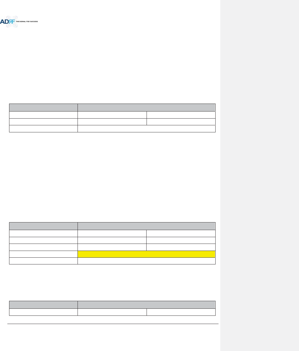
Advanced RF Technologies, Inc.
62
- If calculated composite HE DL input power exceeds the permitted maximum input range, then
additional attenuation will need to be added to the BCU input port so that the calculated HE DL
input power does not exceed 25dBm.
xThe RFU DL input commission level is the combined DL Output ALC Level of the ADX-H-BCU which can be
obtained from the Control page of the ADX-H-BCU.
- The maximum input level of HE RFU will not exceed 10dBm (= 5dBm + 10*log10 (3)) because the
maximum output of BCU each path is limited to 5dBm by the ALC function.
7.2.2.1.2 Example of commissioning value calculation
7.2.2.1.2.1 AT&T signal in the PCS band with multiple technologies (without attenuation)
Table 7-3 shows 2 technologies being used by AT&T within the same band which are inputted into the HE RFU.
Table 7-3 Input signal conditions @HE RFU downlink input
WSP AT&T
Technology
GSM
WCDMA
Total input per band
20.0dBm
20.0dBm
HE Total Input 23.0dBm
xThe downlink input level for each technology should be measured because two technologies (GSM & WCDMA)
are being used by AT&T in the PCS band.
- Total measured input power for GSM is 20dBm and for WCDM is 20dBm.
xThe HE DL maximum input level for each technology can be calculated by adding the back-off value per
technology due to traffic load change (breathing).
xEstimated Total Max Input per band = Total input per band + back-off value per band for breathing.
xHE DL maximum input level becomes the sum of HE DL maximum input level for each technology.
- The sum of HE DL maximum input level for each technology is 28dBm (25.0dBm for GSM +
25.0dBm for WCDMA = 28.0dBm) and this value is 3dB (28dBm – 25dBm) larger than the
maximum DL input of HE RFU.
- If the calculated HE downlink commissioning value exceeds the maximum DL input of HE RFU,
attenuation will need to be added have the calculated HE downlink commissioning level not
exceed 25dBm.
Table 7-4 HE maximum downlink input level without 10dB attenuator
WSP AT&T
Total input per band 20.0dBm 20.0dBm
Back off per band for breathing 5.0dB 5.0dB
Estimated Total Max Input per band
25.0dBm
25.0dBm
Estimated Total Max Input
28.0dBm
Available Max Input
25.0dBm
7.2.2.1.2.2 AT&T signals in the PCS band with multiple technologies (with 10dB of attenuation)
After adding 10dB of attenuation to the system, the input levels per band and HE Total Input can be seen
below:
Table 7-5 HE downlink input signal conditions after adding 10dB attenuator to HE downlink input port
WSP AT&T
Technology
GSM
WCDMA
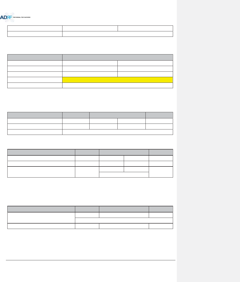
Advanced RF Technologies, Inc.
63
Total input per band
10.0dBm
10.0dBm
HE Total Input
13.0dBm
The RFU can now be commissioned with the 10dB of attenuation by using a DL input commission level of
18dBm.
Table 7-6 HE maximum downlink input level after adding 10dB attenuator to HE downlink input port
WSP AT&T
Total input per band 10.0dBm 10.0dBm
Back off per band for breathing 5.0dB 5.0dB
Estimated Total Max Input per band
15.0dBm
15.0dBm
Estimated Total Max Input
18.0dBm
Available Max Input
25.0dBm
7.2.2.1.2.3 Multiple WSPs’ signals exist in the PCS band (with power ratio)
Table 7-7 displays all the various incoming DL signals that are entering into the HE PCS BCU. The ADX-H-BCU
has total 3 input ports and in the example below each port has been assigned to Sprint, AT&T, and VzW.
Table 7-7 Input signal conditions @HE BCU downlink input
WSP Sprint- CH1 AT&T- CH2 VzW- CH3
Technology
CDMA
GSM
WCDMA
CDMA
Total input per band
5.0dBm
10.0dBm
10.0dBm
7.0dBm
BCU Total Input 14.5dBm
xCalculate maximum DL input level for each WSP factoring in the back-off values.
Table 7-8 HE maximum downlink input level
WSP Sprint- CH1
AT&T- CH2 VZW- CH3
Total input per carrier
5.0dBm
10.0dBm
10.0dBm
7.0dBm
Back off per band for breathing 4.0dB 5.0dB 5.0dB 4.0dB
Estimated Total Max Input per carrier 9.0dBm
15.0dBm
15.0dBm
11.0dBm
18.0dBm
xBased on the calculated maximum DL input level for each port, the user should decide on a target maximum
Input power for each BCU port.
- Targeted maximum Input power for each BCU port should not be less than the calculated
maximum DL input level for each port and should not exceed the maximum input level, 25dBm.
Table 7-9 Targeted maximum input power
WSP Sprint- CH1
AT&T- CH2 VZW- CH3
Targeted maximum input power
9.0dBm
18.0dBm
11.0dBm
19.2dBm
Targeted DL Output Power Ratio set by user
30.0%
20.0%
50.0%
xCalculate the DL maximum output power of BCU based on targeted maximum Input power for each BCU port.
- The highest power ratio that has been set is VZW- CH3 @ 50%. The ADX-H-BCU will apply
attenuation to this port to set the maximum output power to 5dBm, therefore 6dB of
attenuation will be applied to this port.
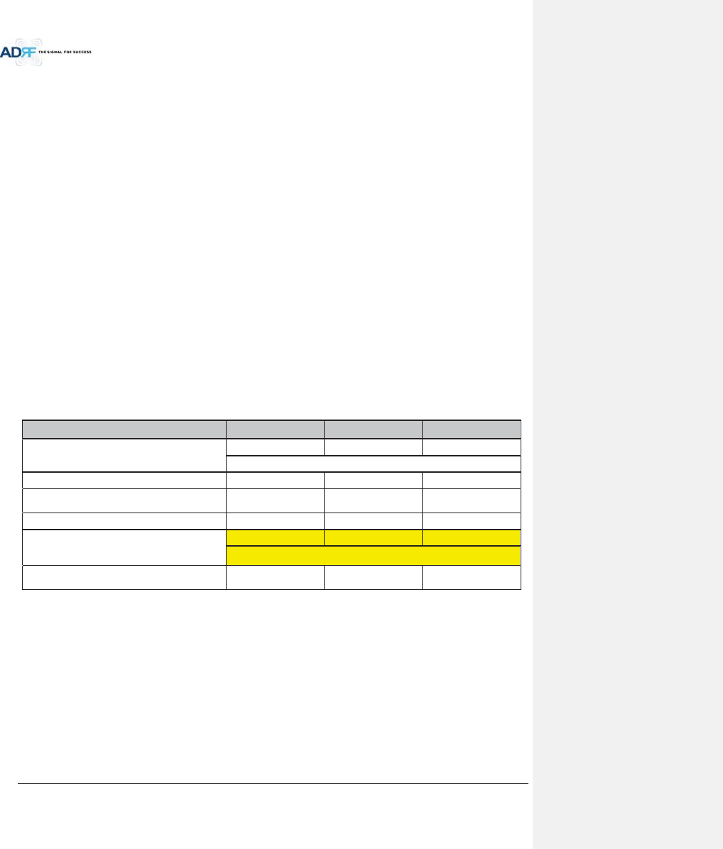
Advanced RF Technologies, Inc.
64
- The attenuation and DL output ALC level for the other ports are set based on the formula below
to keep the power ratio between BCU ports.
!The maximum output power for the specified path = 10*log10[10^(Max_ALC/10)x(Pwr_Ratio)/
Max_Ratio]
Max_ALC: DL output ALC level for the path with maximum power ratio = 5dBm
Pwr_Ratio: Targeted DL output power ratio value for the specified path
Max_Ratio: maximum power ratio value
!The attenuation for the specified path = The targeted maximum input power for the specified path -
The maximum output power for the specified path
!DL output ALC level = The targeted maximum input power for the specified path - The attenuation
for the specified path
!The path for AT&T- CH2
The maximum output power = 10*log10[10^(5/10)x20%/50%] = 1.02dBm
The ATT value = 18.0dBm-1.02dBm=16.98dB Î 16.5dB(the control step of used attenuator is
0.5dB)
DL output ALC level = 18dBm – 16.5dB = 1.5dBm
!The path for Sprint- CH1
The maximum output power = 10*log10[10^(5/10)x30%/50%] = 2.78dBm
The ATT value = 9.0dBm-2.78dBm=6.22dB Î 6.0dB(the control step of used attenuator is 0.5dB)
DL output ALC level = 9.0dBm – 6.0dB = 3.0dBm
- The DL maximum output power of BCU is the sum of maximum output power for each port and
this power becomes the HE RFU input commissioning level.
- The maximum input level of HE RFU should be less than 10dBm (= 5dBm + 10*log10 (3)) because
the maximum output of BCU per each path doesn’t exceed 5dBm by ALC function.
Table 7-10 Maximum Output Power per carrier
WSP Sprint AT&T VZW
Targeted maximum input power
9.0dBm
18.0dBm
11.0dBm
19.2dBm
Targeted DL Output Power Ratio set by user 30.0% 20.0% 50.0%
DL maximum output power
(ATT control step, 0.5dB is not considered)
2.78dBm 1.02dBm 5.0dBm
ATT value
6.0dB
16.5dB
6.0dB
DL output ALC level or
DL Maximum output power
(ATT control step, 0.5dB is considered)
3.0dBm
1.5dBm
5.0dBm
8.2dBm(RFU DL Input commissioning level)
DL Output Power Ratio
considering ATT control step 0.5dB
30.37% 21.50% 48.13%
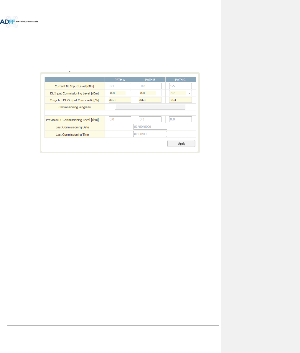
Advanced RF Technologies, Inc.
65
7.2.2.1.3 HE BCU Commissioning
When performing BCU commissioning, the user will need to enter the DL input commissioning level and
Targeted DL Output Power Ratio for each RF path. Refer to section 7.2.2.1 to calculate DL input commissioning
level. If a port is not being used, the DL Input Commissioning Level should be set to “disabled”.
7.2.2.1.3.1 HE BCU Commissioning Procedure
xGo to Install page of the BCU on the Web-GUI
Figure 7-6 BCU Install Window
xSelect a DL Input Commissioning Level for each RF path
- DL Input Commissioning Levels range is 0~+25dBm (0.5dB step)
xEnter HE BCU downlink output power ratio for each port
xPress the “Apply” button
xThe attenuation value and output ALC level for each DL/UL path will be set automatically based on the HE BCU
downlink input commissioning level and downlink output power ratio for each port.
xThe BCU will check to see if ALC is active on any of the ports.
- During the commissioning routine, if ALC is activated, a popup message will appear stating that
ALC is running. If this is the case, then there is a chance that the “back-off” value needs to be
increase to allow more breathing room.
xThe BCU checks to see if the BCU has any alarms.
- If a soft fail is present, the system will prompt the user whether or not they would like to
continue.
- If hard fail is present, the commissioning process will stop immediately.
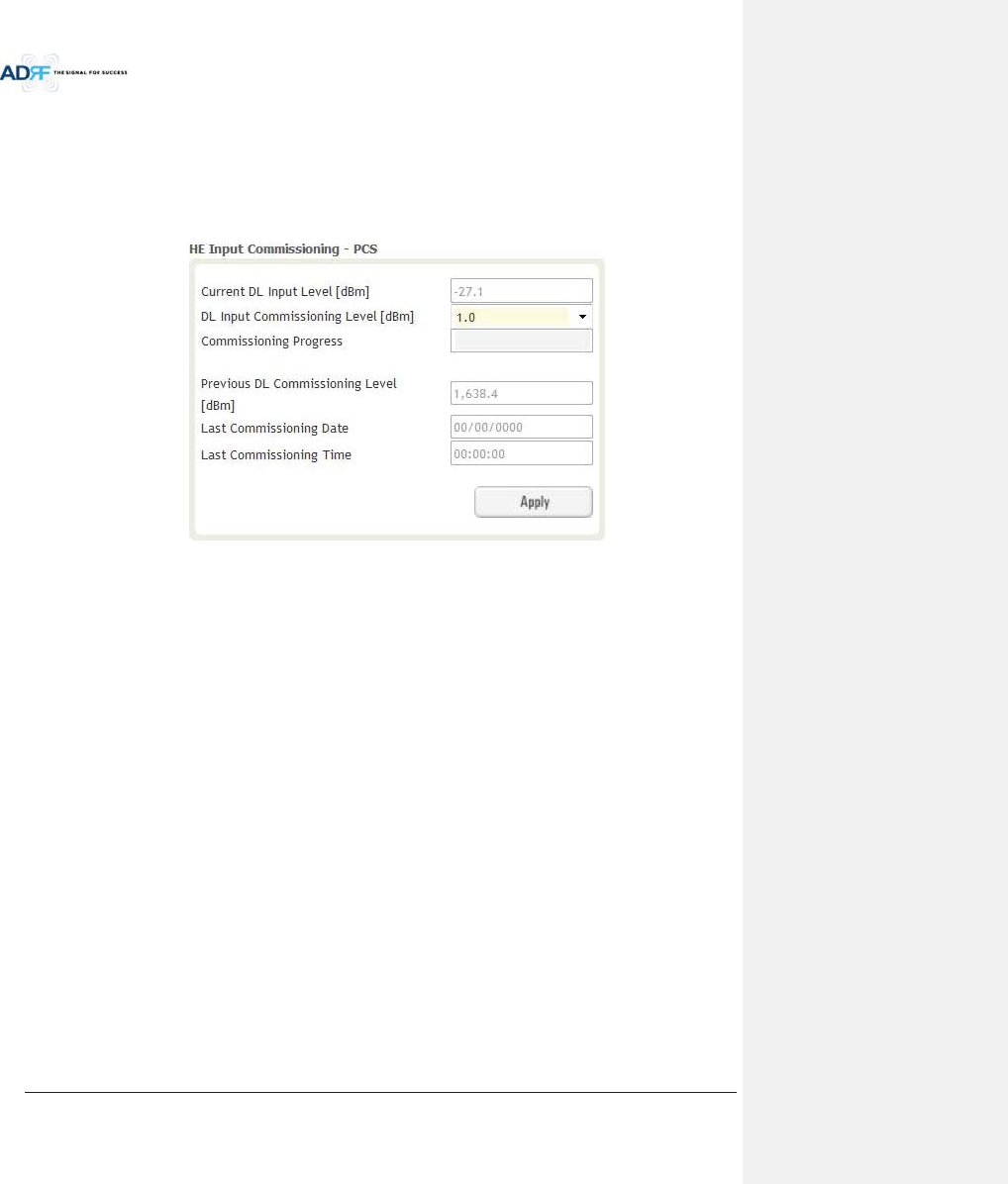
Advanced RF Technologies, Inc.
66
7.2.2.1.4 HE RFU commissioning
If a BCU is being used in the system, the BCU should be commissioned before commissioning the HE RFU.
For RFU commissioning, the user will need to calculate the DL input commissioning level. Refer to section
7.2.2.1 to for information to determine the DL input commissioning level.
7.2.2.1.4.1 HE RFU commissioning Procedure
xGo to Install page of RFU on the Web-GUI
Figure 7-7 RFU Install Window
xEnter HE RFU downlink input commissioning level
- Input range: 0~+25dBm, 0.5dB step
xPress the “Apply” button
xThe attenuation levels will be set automatically based on DL Input Commissioning Level that is selected.
xChecks to see if DL input is low.
- During the commissioning routine, if DL input level is 10dB less than commissioning level, a
popup message will appear stating that DL input is low. If this is the case, then there is a chance
that the “back-off” value needs to decrease breathing room.
xChecks to see if ALC is active.
- During the commissioning routine, if ALC is activated, a popup message will appear stating that
ALC is running. If this is the case, then there is a chance that the “back-off” value needs to be
increase to allow more breathing room.
xChecks to see if the RFU has any alarms.
- If a soft fail is present, the system will prompt the user whether or not they would like to
continue.
- If hard fail is present, the commissioning process will stop immediately.
xCommissioning is successfully completed.
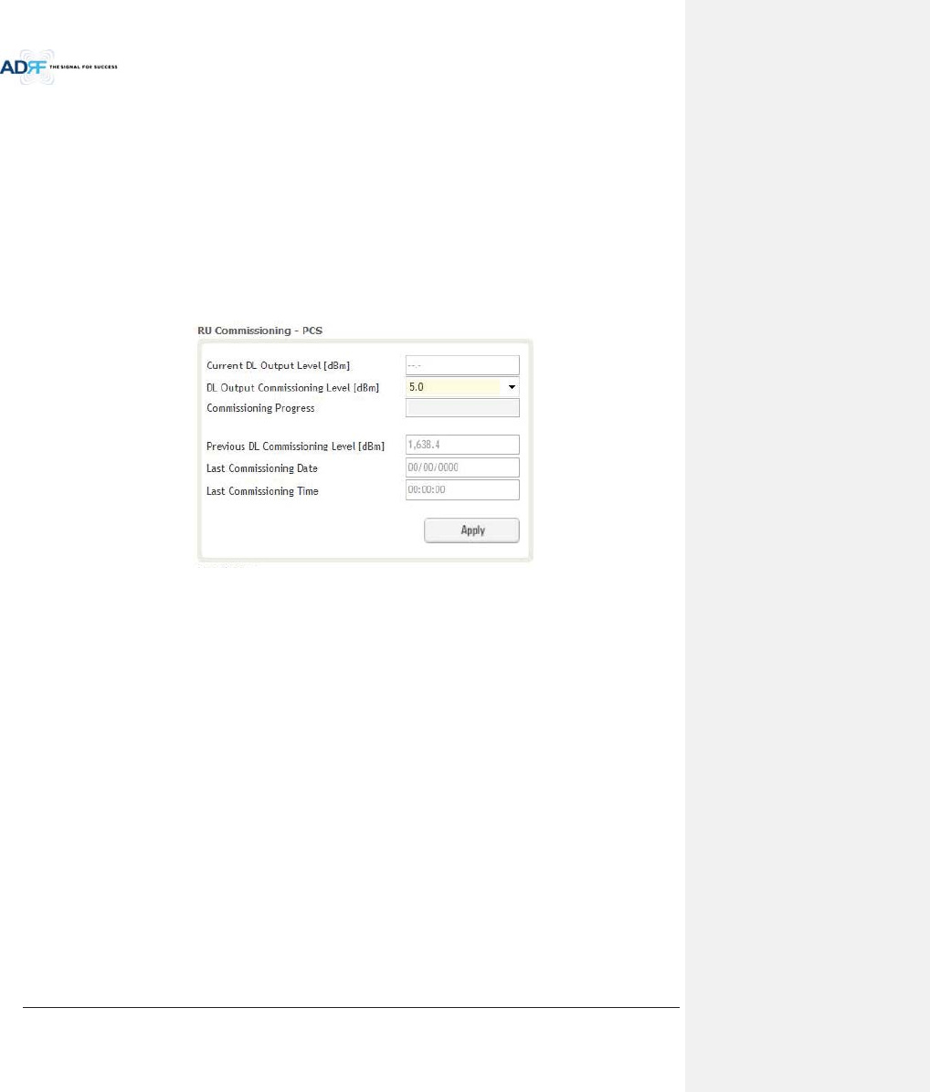
Advanced RF Technologies, Inc.
67
7.2.3 HRU Commissioning
HRU composite downlink output level can be determined using simulation tools like iBwave. User should
simulate this output level in order to ensure that all service areas have sufficient coverage.
xThe simulated composite DL output power value should not exceed the maximum output level of the HRU,
which is 43dBm.
xThe simulated composite DL output power value would be used as HRU DL commissioning output level. DL
attenuation value will be adjusted automatically based on this simulated value HRU commissioning level.
For HRU commissioning, user should enter information on DL output commissioning level. Refer to section
7.2.2.1 to calculate DL output commissioning level.
xGo to Install page of Remote Module on the webGUI
Figure 7-8 Remote Module Install Window
xEnter HRU downlink output commissioning level
- Output range: 5~+43dBm, 0.5dB step
xPress the “Apply” button
xThe attenuation level for each DL/UL path will be set automatically based on DL Output Commissioning Level
that is entered
xChecks to see if DL output is low.
- During the commissioning routine, if DL output level is 10dB less than commissioning level, a
popup message will appear stating that DL output is low. If this is the case, then there is a chance
that the “back-off” value needs to decrease breathing room.
xChecks to see if ALC is is active.
- During the commissioning routine, if ALC is activated, a popup message will appear stating that
ALC is running. If this is the case, then there is a chance that the “back-off” value needs to be
increase to allow more breathing room.
xChecks to see if the Sub-RU has any alarms.
- If a soft fail is present, the system will prompt the user whether or not they would like to
continue.
- If hard fail is present, the commissioning process will stop immediately.
xCommissioning is successfully completed.

Advanced RF Technologies, Inc.
68
7.3 DAS Install Verification
7.3.1 Setting SNMP & Remote IP
xGo to Install page of NMS (refer to section 8.2.4.1.4)
xWhen external modem box is connected, user should set SNMP & Remote IP information.
7.3.2 Verification through Web based GUI
xGo to System information page of System (refer to section 8.2.5.4.1)
- Check if Remote Module with same frequency band exist more than one within one HRU.
- Check if there are any noncommissioned modules in HE or RU.
- Check if any critical alarms are present.
7.3.3 UL noise power detection
When the UL noise levels is larger than the expected value, ADX DAS has a function that will measure the
uplink noise for each HRU and will generates a report with the UL noise levels. This will help the user determine
which HRU might be the cause of the elevated UL noise.
xUL noise power measurement can be performed for only one frequency band at a time.
xFor more information, refer to section 8.2.3.3.3.
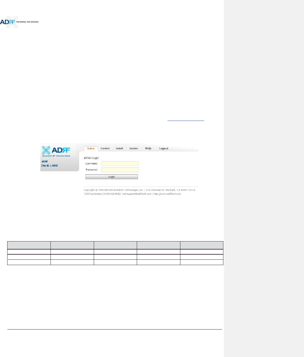
Advanced RF Technologies, Inc.
69
8. WEB-GUI
8.1 Web-GUI Setup
The Web-GUI allows the user to communicate with the DAS system either locally or remotely. To connect to
the DAS system locally, you will need a laptop with an Ethernet port and a RJ-45 crossover cable. To connect to
the DAS system remotely, you will need to have an active internet connection and the ADX system must have and
external modem box connected to the ADX.
8.1.1 DAS system/PC Connection Using Web-GUI
xVerify that your Local Area Connection is set to Obtain an IP address automatically under the Internet Protocol
(TCP/IP) properties
- If you are connecting to the unit remotely (use of a modem), then skip this and next step.
xConnect the RJ-45 crossover cable between the laptop’s Ethernet port and the repeater’s Ethernet port
xLaunch an Internet Browser
xType the following IP address into the address bar of Microsoft Internet Explorer: http://192.168.63.1
- If you are connecting to the unit remotely, then type the IP address of the modem to connect to
the unit
xThe following login screen will appear:
Figure 8-1 Login screen
If you are not the Administrator, please type in your assigned username & password which you should have
received from the Administrator.
Table 8-1 Account Information for Login
Account type Show items Control Items Default ID Default Password
Administrator
all Items
all items
admin
admin
User
restricted items
restricted items
adrf
adrf
Guest
restricted items
read-only
guest
guest
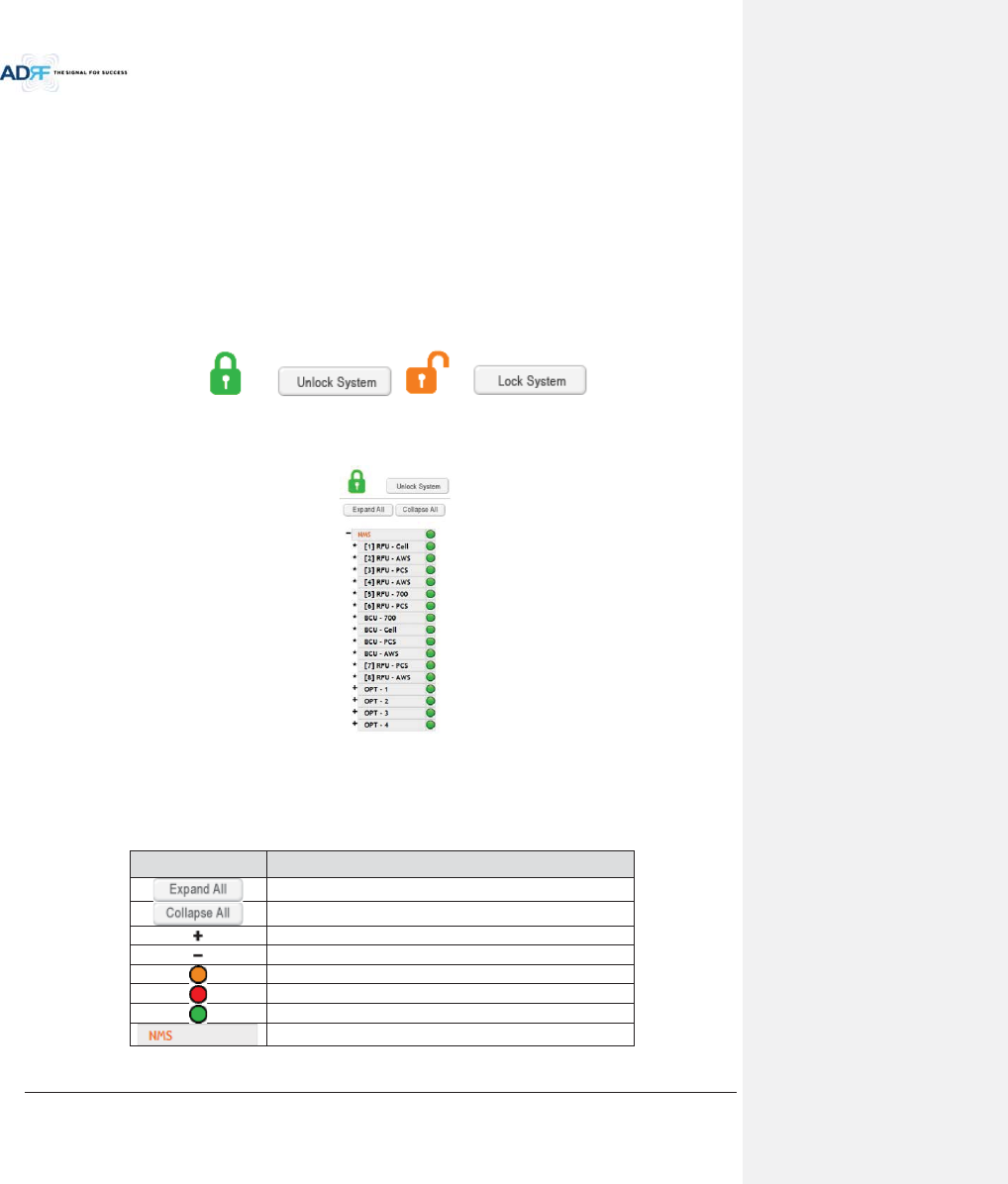
Advanced RF Technologies, Inc.
70
8.2 Administrator/User Mode
8.2.1 Common
8.2.1.1 Navigation tree Lock/Unlock
When the system is “Locked”, a green lock icon will appear above the navigation tree. When the system is
locked, new devices cannot be added. Any devices added to the system when the system is “Locked” will not be
detected by the NMS. After a system has been commissioned properly, the system should be left in the “Locked”
position. To unlock the system, click on the “Unlock System” button to the right of the icon.
When the system is “Unlocked”, an orange icon will appear above the navigation tree. When the system is
unlocked, new devices added to the system will be automatically detected. Once the new hardware appears in the
system tree, then the system can be locked. To lock the system, click on the “Lock System” button to the right of
the icon.
Figure 8-2 Navigation tree Lock/Unlock
8.2.1.2 Navigation Tree
Figure 8-3 Navigation tree
The navigation tree located on the left hand side of the Web-GUI allows the user to switch between the
various modules that are connected to the system.
Table 8-2 Navigation tree
Parameters Description
Expands the entire navigation tree
Collapses the entire navigation tree
The module has the expandable subordinate modules
The branch is currently expanded
The module has soft fail alarm
The module has hard fail alarm
The module has no alarms (normal)
The selected module will have orange colored text
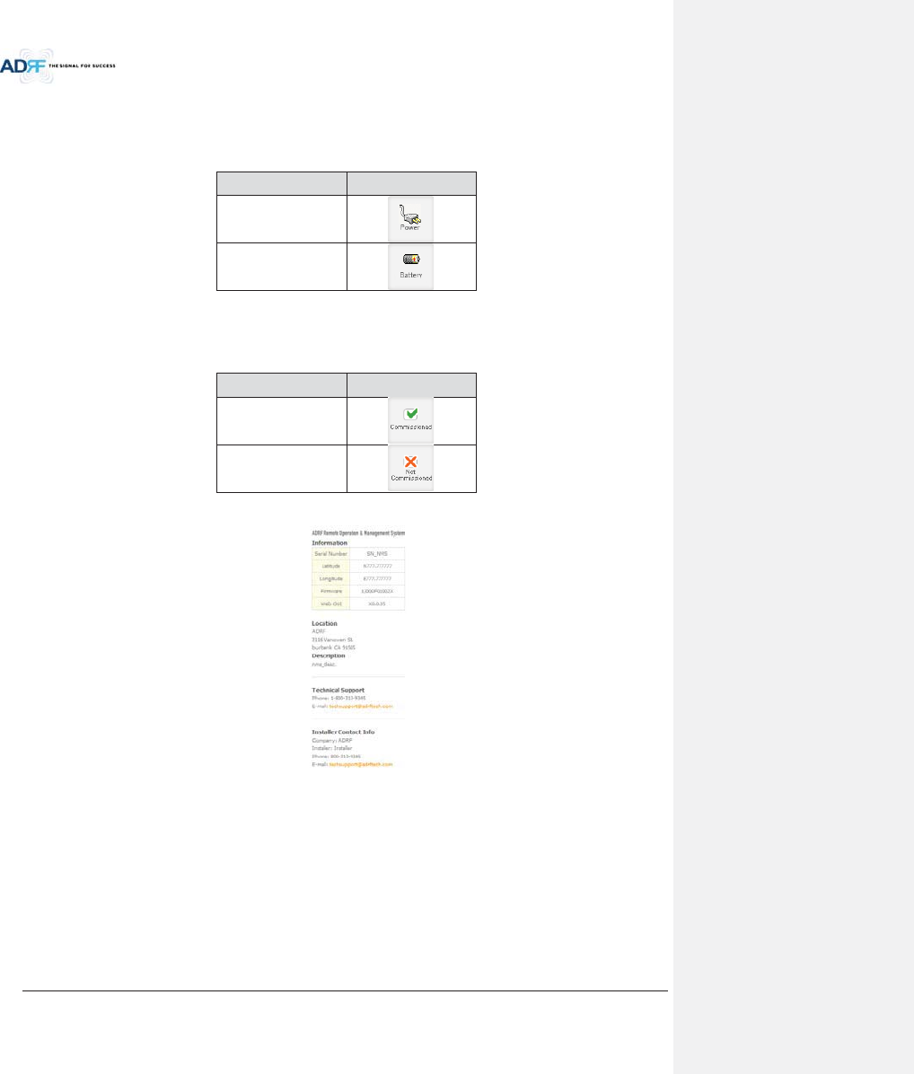
Advanced RF Technologies, Inc.
71
8.2.1.3 Power Status
Display the power source that is currently being used.
Table 8-3 Power Supply Status
Input Power Status
Display Image
AC
Battery
8.2.1.4 Commissioning Status
Display whether or not the module has successfully been commissioned.
Table 8-4 Commissioning ICON
Status Display Image
Commissioned
Not-Commissioned
8.2.1.5 Information
Figure 8-4 ADX DAS General Information
xInformation: Displays the serial number, latitude/longitude, firmware version of selected module, and Web
GUI version of the NMS.
xLocation: Displays the address where the ADX DAS is installed.
xDescription: Displays the description of selected module. The description of each module can be edited from
the Install tab. It is recommended to use the location of the module as the description. This description
information can be seen when hovering over the device tree in order to easily identify each component.
xTechnical Support: Displays ADRF’s Technical Support contact information.
xInstaller Contact Info: Displays the contact information of the installer.
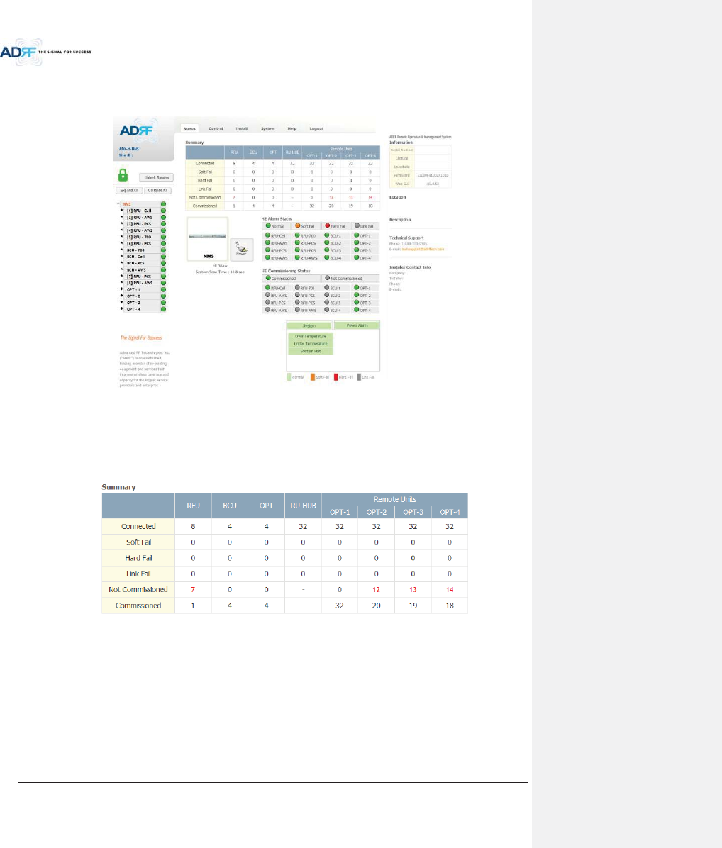
Advanced RF Technologies, Inc.
72
8.2.2 Status Tab
8.2.2.1 Status – NMS
Figure 8-5 Status - NMS
The NMS Status page provides an overall view of how the system is performing. From the NMS Status page,
the user can see what modules are connected to ADX DAS. In addition, the user can see if any alarms are present
in the system and also the commissioning status of each module.
8.2.2.1.1 System Summary
Figure 8-6 System Summary
The Summary section provides the user with the number of components physically connected, the number of
soft/hard/link fails present in the system, and also the number of commissioned and non-commissioned
componnets.
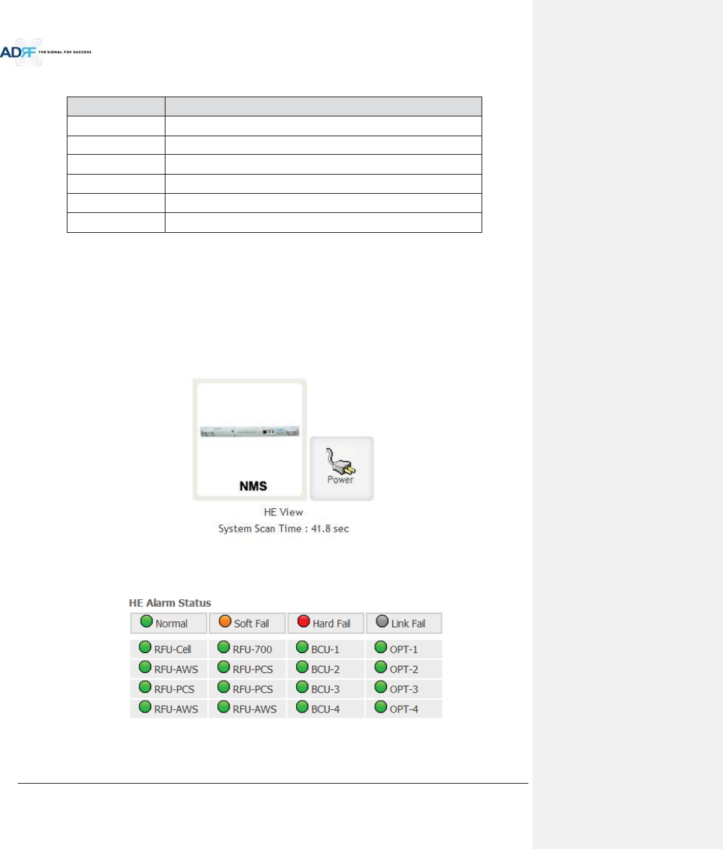
Advanced RF Technologies, Inc.
73
Table 8-5 System Summary Description
Parameters Description
Connected Display the number of modules physically connected to ADX DAS
Soft Fail Display the number of soft fail present on each module
Hard Fail Display the number of hard fail present on each module
Link Fail Display the number of link fail present on each module
Not Commissioned
Display the number of non-commissioned or commission failed module
Commissioned Display the number of successfully commissioned module
8.2.2.1.2 HE View / HRU View, System Scan Time
xHE View/RU View
- Displays whether the NMS is set to HE view or HRU view.
- Refer to section 3.1.1.4
xSystem Scan Time
- Displays the time it takes to scan and update the information of all the modules that are on the
navigation tree. This time will increase as more components are added to the system.
-When Navigation Tree is unlocked, the user should wait at least the “System Scan Time” for the
system to detect newly added hardware.
Figure 8-7 System scan time, HE view/RU view
8.2.2.1.3 HE Alarm Status
Display the alarm status of each HE component.
Figure 8-8 HE alarm status
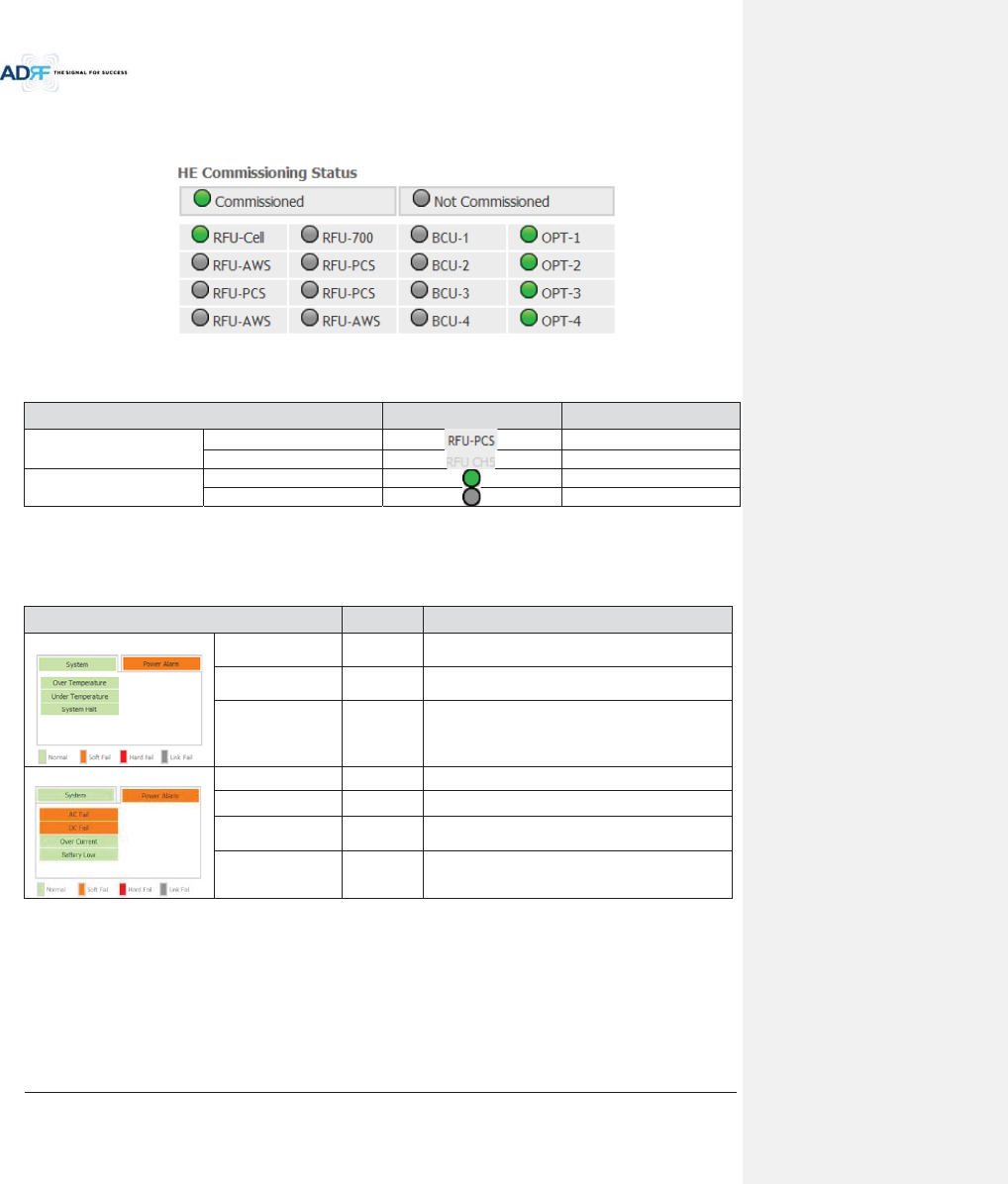
Advanced RF Technologies, Inc.
74
8.2.2.1.4 HE Commissioning Status
Display commissioning status of each HE component.
Figure 8-9 HE Commissioning status
Table 8-6 Description for HE Commissioning status
Status Display Description
Installed Status
Physically Installed
Text is black
Physically Not-Installed
Text is gray
Commissioning Status
Success
Green
Failed or not commissioned
Gray
8.2.2.1.5 Alarm
Displays alarm status of the NMS. If an alarm is present in the system, the color of the system alarm tab will
change according to the type of failure.
Table 8-7 Description for NMS alarm
Alarm Severity
Description
System
Over Temperature
Hard Fail /
Soft Fail
Temperature of NMS is higher than the threshold
level for over temperature alarm
Under Temperature
Soft Fail
Temperature of the NMS is lower than the threshold
level for under temperature alarm
System Halt
Hard Fail
HE system halt
Power Alarm
AC Fail Soft Fail
AC power is operating outside of its normal range
DC Fail Soft Fail
DC power is operating outside of its normal range
Over Current
Hard Fail
Total current of HE is higher than the threshold level
for over current alarm
Battery Low Soft Fail
Voltage of battery connected to HE PSU is lower than
the defined threshold
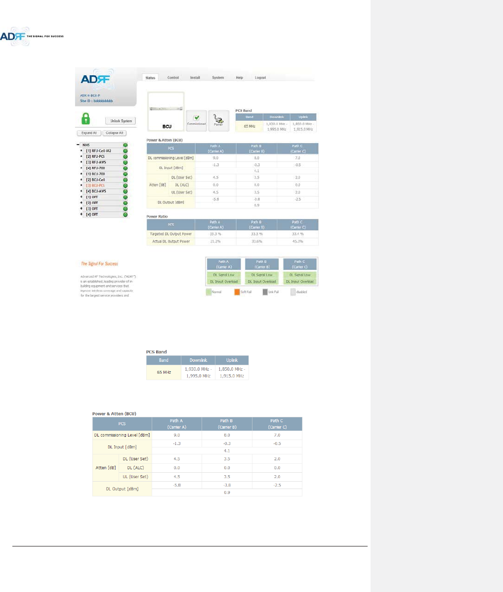
Advanced RF Technologies, Inc.
75
8.2.2.2 Status – BCU
Figure 8-10 Status – BCU
8.2.2.2.1 Band
Displays the bandwidth and the frequency ranges for DL and UL of the BCU module.
Figure 8-11 Status – BCU Band
8.2.2.2.2 Power & Atten
Figure 8-12 Status – BCU Power & Atten
xDL Commissioning Level: Displays the commissioning level for each individual RF path. If unit has not
been commissioned, “Not Commissioned” will be displayed.
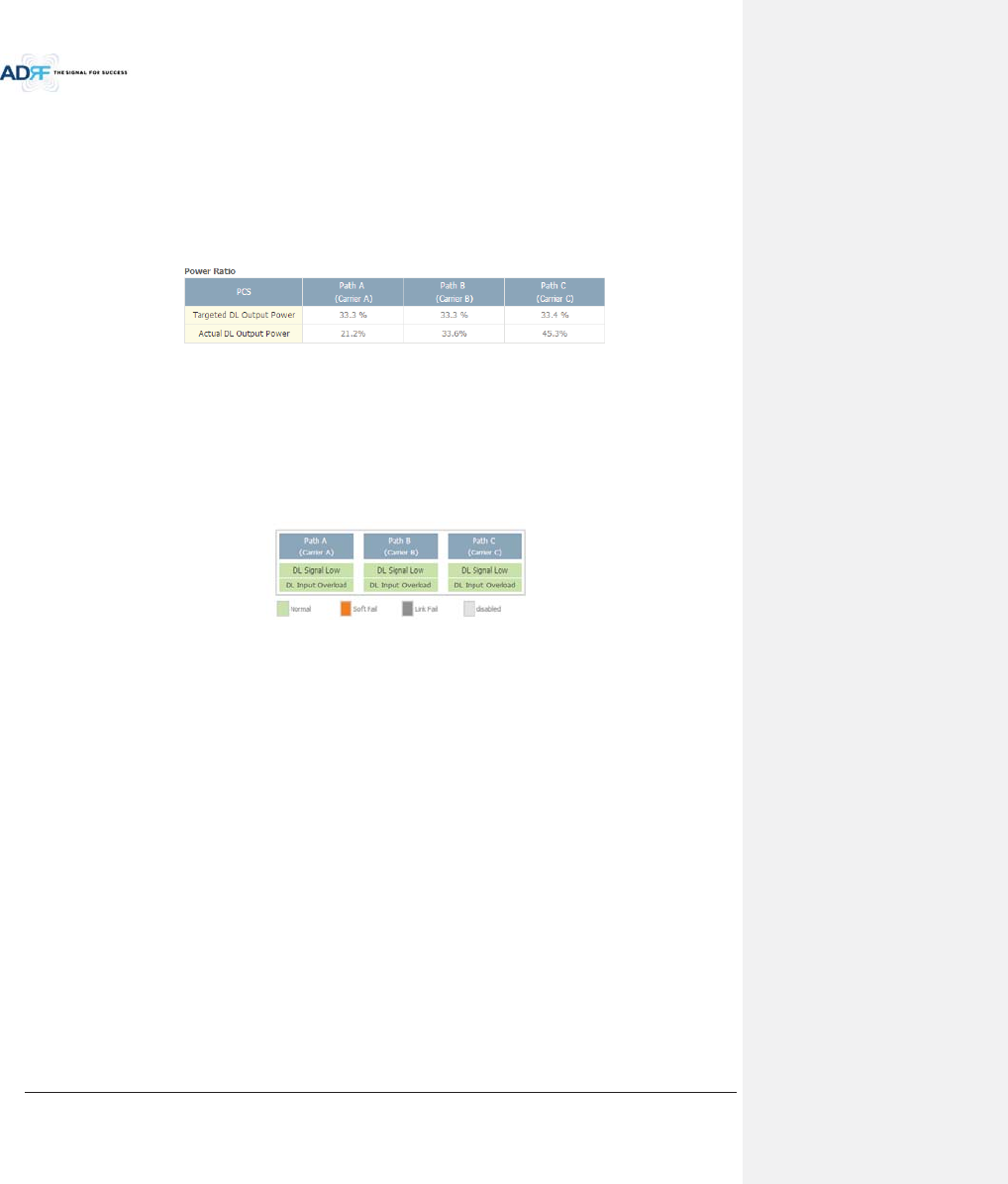
Advanced RF Technologies, Inc.
76
xDL Input: Displays the currently incoming signal strength of each RF path along with the composite DL
input power of all 3 RF paths.
xAtten: Displays the attenuation values that the system is currently using which is defined by the
power ratios specified by the user.
xDL Output: Displays the output value for each RF path along with the composite DL output power of
all 3 RF paths. The DL Output level for each RF path will not exceed 5dBm and the composite output
power will not exceed 10 dBm.
8.2.2.2.3 Power Ratio
Figure 8-13 Status – BCU Power Ratio
xTargeted DL Output Power: Displays desired power ratios specified by the user. If unit has not been
commissioned, “Not Commissioned” will be displayed.
xActual DL Output Power: Displays the currently power ratios that the system is using. These values
will fluctuate based on the amount of traffic that is in the system.
8.2.2.2.4 Alarm
Displays the current alarm status of each individual RF path. Parameters for both DL Signal Low and DL Input
Overload can be specified from the Control tab.
Figure 8-14 Status – BCU Alarm
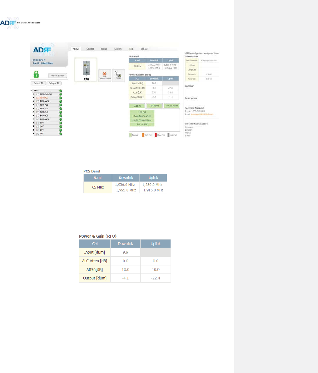
Advanced RF Technologies, Inc.
77
8.2.2.3 Status – RFU
Figure 8-15 Status – RFU
8.2.2.3.1 Band
Displays the bandwidth and the frequency ranges for DL and UL of the RFU module.
Figure 8-16 Status – RFU Band
8.2.2.3.2 Power & Gain (Admin/User)
Admin Mode- Displays the Downlink Input/output, Downlink/Uplink Attenuation, and Uplink
Output.
User Mode- Displays the Downlink Input, Downlink/Uplink Attenuation, and Uplink Output.
Figure 8-17 Power & Gain Display (Admin)
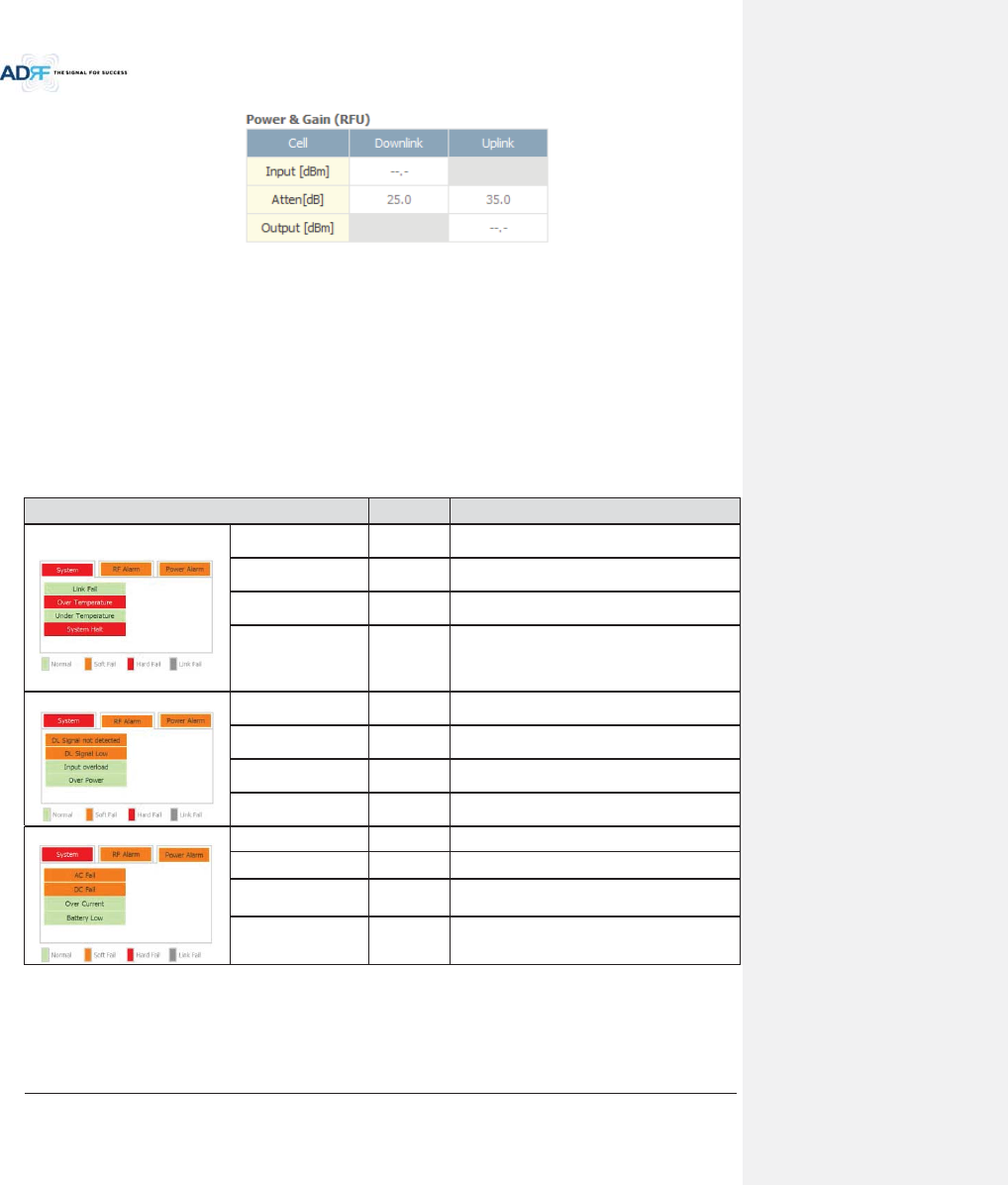
Advanced RF Technologies, Inc.
78
Figure 8-18 Power & Gain Display (User)
xInput [dBm]: Displays the Downlink RF input level which comes from the ADX-H-BCU or BTS. This value should
be between 0 to 25 dBm.
xALC Atten [dB]: The amount of attenuation that is being used by the system when ALC is active.
xAtten [dB]: The amount of attenuation that has been set manually by the user.
xOutput [dBm]: The downlink/uplink output power of the RFU and NOT the output power of the RU.
8.2.2.3.3 Alarm
Displays System, RF, and Power Alarms. If an alarm is present in the system, then the color of the tab will
change according to the type of failure.
Table 8-8 RFU Alarm Status
Alarm Severity
Description
System
Link Fail Soft Fail
A component is physically connected, but the
NMS is unable to communicate with it.
Over Temperature
Hard Fail /
Soft Fail
The temperature of NMS is higher than the
threshold level for over temperature alarm.
Under Temperature
Soft Fail
The temperature of NMS is lower than the
threshold level for under temperature alarm.
System Halt
Hard Fail
System will go into a “System Halt” state when a
hard fail alarm does not clear after 10 checks.
System Halt can only be cleared with a power
cycle, reboot, or factory settings.
RF Alarm
DL Signal not detected
Soft Fail
Downlink input signal is lower than the defined
threshold by user.
DL Signal Low Soft Fail
Downlink input signal is lower than the defined
threshold by user.
Input Overload
Hard Fail /
Soft Fail
Downlink input signal is higher than the defined
threshold.
Overpower
Hard Fail /
Soft Fail
Uplink output signal is higher than the defined
threshold by user.
Power Alarm
AC Fail Soft Fail
AC power is not operating within parameters.
DC Fail Soft Fail
DC power is not operating within parameters.
Over Current
Hard Fail
Total current of HE is higher than the threshold
level for over current alarm.
Battery Low Soft Fail
Voltage
of battery connected to HE PSU is lower
than the defined threshold.
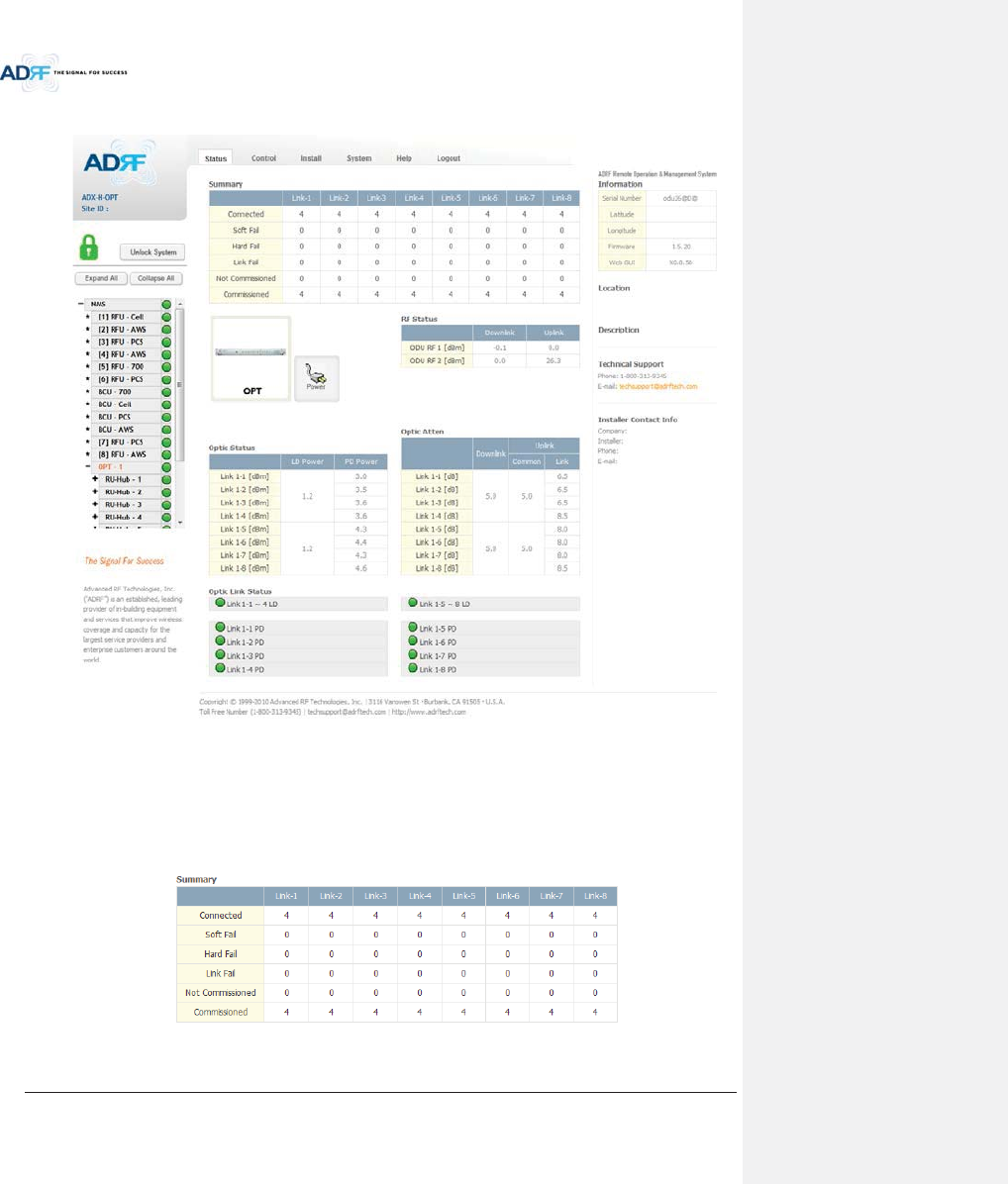
Advanced RF Technologies, Inc.
79
8.2.2.4 Status – ODU
Figure 8-19 Status - ODU
8.2.2.4.1 Summary
The Summary section displays the number of remote modules that are physically connected, the number of
soft/hard/link fail alarms, and the number of Remote Module that have been commissioned and the number of
Remote Module that need to be commissioned.
Figure 8-20 Summary (Status – ODU)
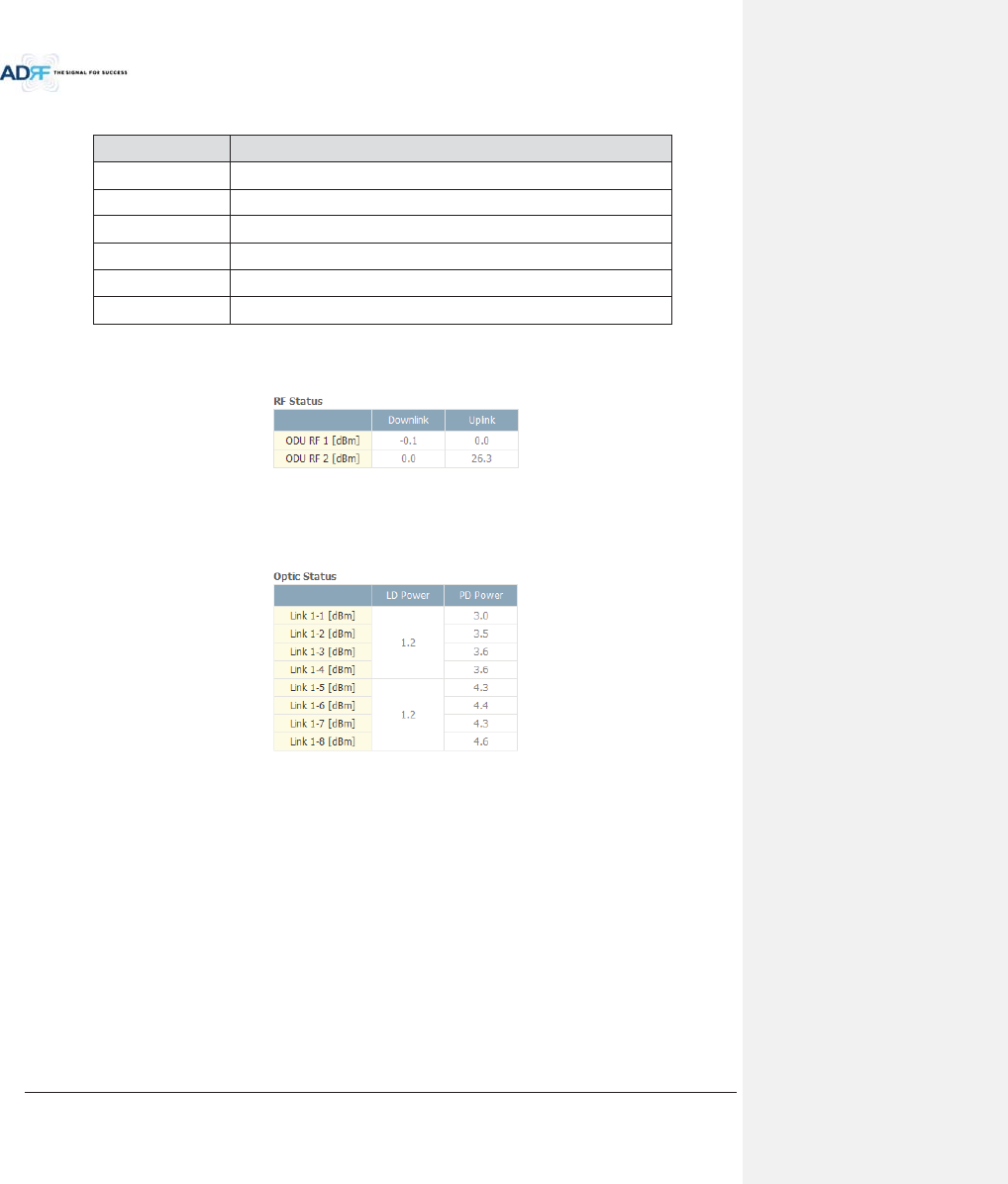
Advanced RF Technologies, Inc.
80
Table 8-9 Summary Description
Parameters Description
Connected Displays the number of Remote Module’s connected to the ADX-RACK-ODU
.
Soft Fail Displays the total number of soft fail present.
Hard Fail Displays the number of hard fail present on each module.
Link Fail Displays the number of link fail present on each module.
Not Commissioned
Displays the number of non-commissioned or commission failed module.
Commissioned Display the number of successfully commissioned module
8.2.2.4.2 RF Status
Displays the DL input power and the UL output power for each ODU.
An ADX-RACK-ODU is composed of 2 ODUs.
Figure 8-21 RF Status (Status – ODU)
8.2.2.4.3 Optic Status
Display LD Power and PD Power for each optic path. LD Power is the power that is being sent to the HRU and
PD Power is the power that is being received from the RU.
Figure 8-22 Optic Status (Status – ODU)
8.2.2.4.4 Optic Atten (Admin Only)
The ADX-H-ODU has 3 types of attenuators.
Downlink Common Attenuator- Displays the common attenuation level on the DL path.
Uplink Common Attenuator- Displays the common attenuation level on the UL path.
Uplink Optic Attenuator- Displays the amount of attenuation used at each optical link.
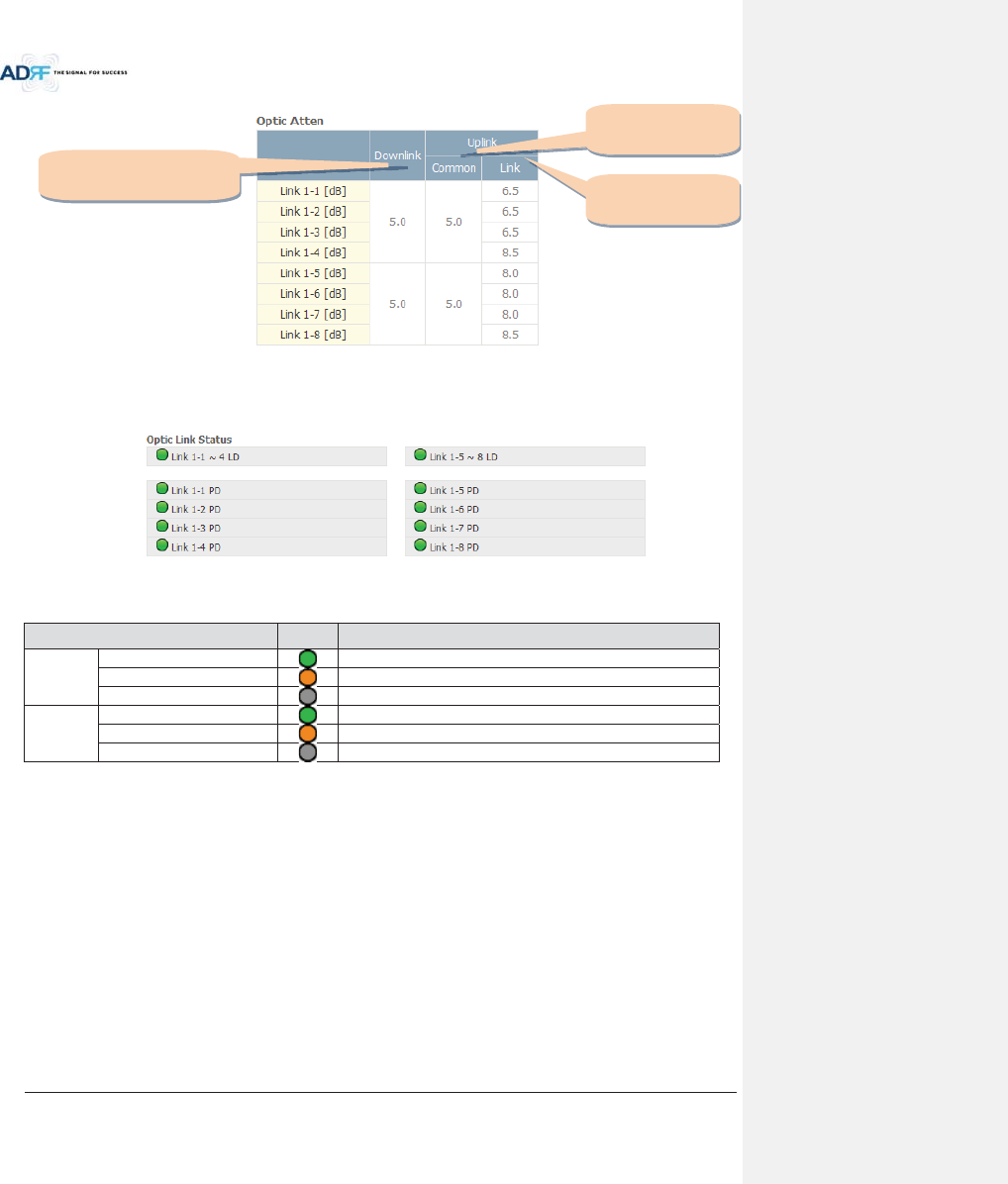
Advanced RF Technologies, Inc.
81
Figure 8-23 Optic Attenuation (Status – ODU)
8.2.2.4.5 Optic Path Status
Displays the optic status for each optic path
Figure 8-24 Optic Path Status (Status – ODU)
Table 8-10 Description for optic path status
Status
Display
Description
LD Status
Normal
Green, optic signal being sent to Master HRU is > -5dBm
LD fail
Orange, optic signal being sent to Master HRU is < -5dBm
Not Connected
Gray, no connection between ODU and Master RU
PD Status
Normal
Green, optic signal being received from Master HRU is > -10dBm
PD fail
Orange, optic signal being received from Master HRU is < -10dBm
Comm Fail or Not Connected
Gray, no connection between ODU and Master RU
Downlink
Common attenuator
Uplink
Common attenuator
Uplink
Optic attenuator
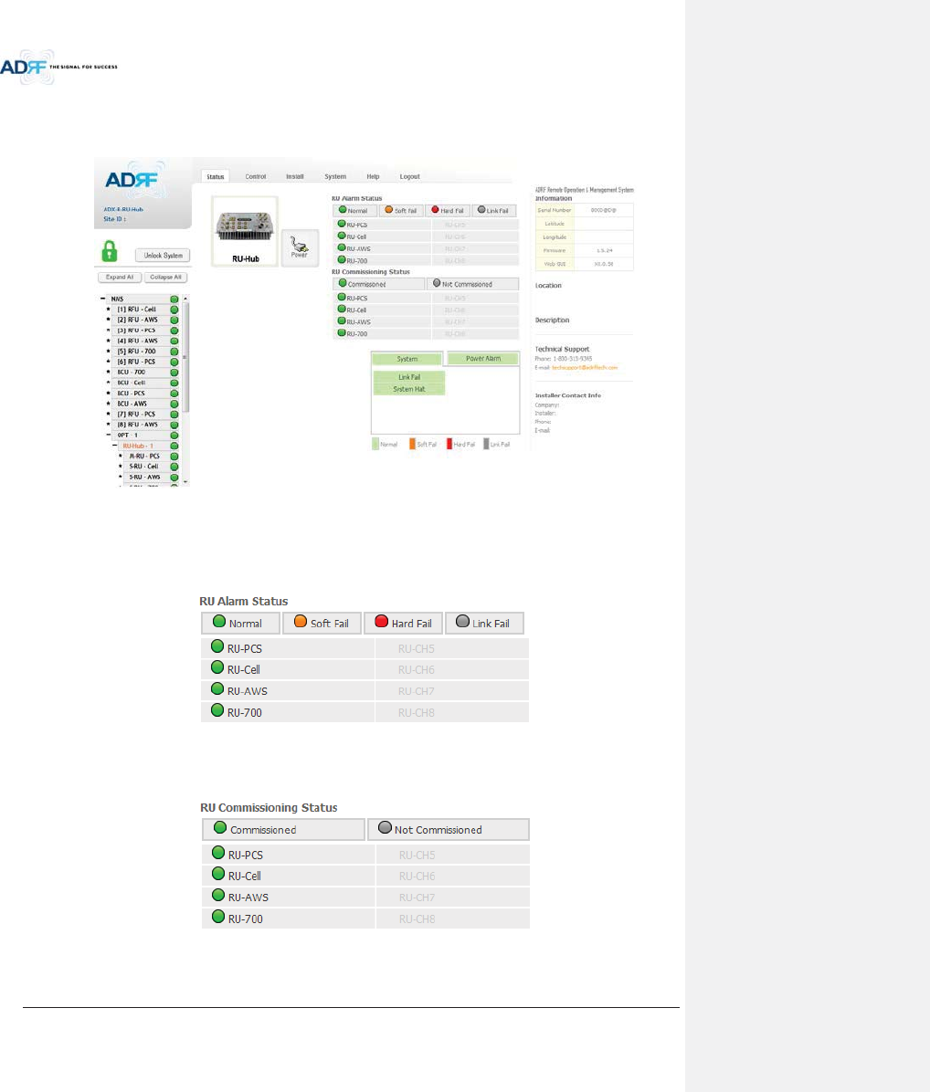
Advanced RF Technologies, Inc.
82
8.2.2.5 Status – HRU Hub
RU-Hub is not separate module but is integrated into the master RU. The picture of HRU Hub displayed on
web based GUI is same as the picture of master RU.
Figure 8-25 Status - HRU Hub
8.2.2.5.1 RU Alarm Status
The HRU Hub can support up to 8 remote modules. The HRU alarm status displays the alarm status of each
remote module.
Figure 8-26 RU Alarm Status (Status - HRU Hub)
8.2.2.5.2 RU Commissioning Status
Display the Commissioning status of each Remote Module.
Figure 8-27 RU Commissioning Status (Status - HRU Hub)
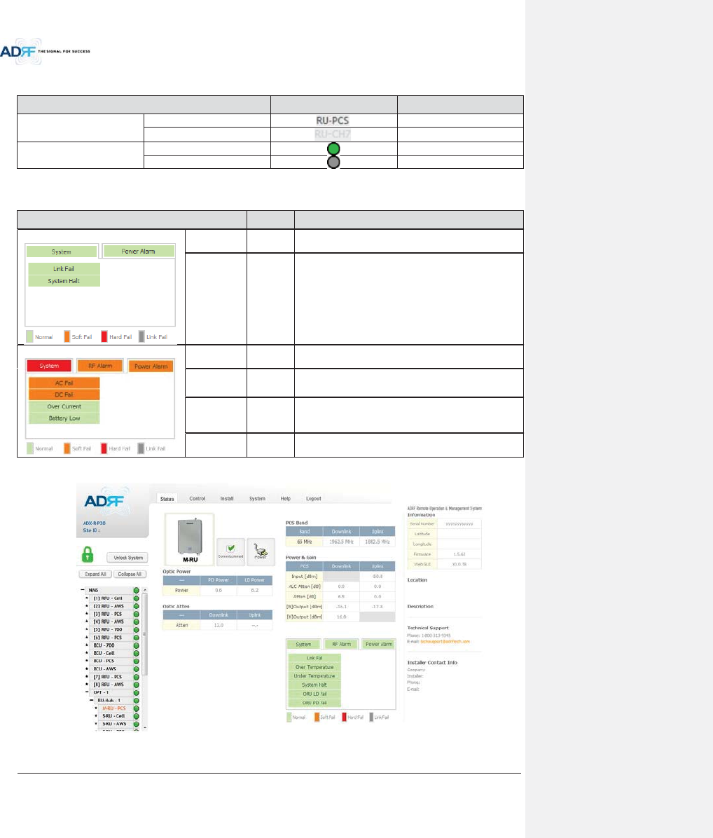
Advanced RF Technologies, Inc.
83
Table 8-11 Description for HRU Commissioning status
Status Display Description
Installed Status
Installed
Text is black
Not-Installed
Text is gray
Commissioning Status
Success
Green
Fail or not yet
Gray
8.2.2.5.3 Alarm
Table 8-12 Alarm Status (Status - HRU Hub)
Alarm
Severity
Description
System
Link Fail
Soft Fail
Present when a module cannot communicate with the
NMS
System Halt
Hard Fail
System will go into a “System Halt” state when a hard
fail alarm does not clear after 10 checks.
System Halt
can only be cleared with a power cycle, reboot, or
factory settings.
Power Alarm
AC Fail
Soft Fail
AC power is not within parameters.
DC Fail
Soft Fail
DC power is not within parameters.
Over Current
Hard Fail
Total current of HRU is
higher than the threshold level
for over current alarm
Battery Low
Soft Fail
Voltage of battery connected to HRU PSU is lower than
the defined threshold
8.2.2.6 Status – Remote module
Figure 8-28 Status – Remote Module
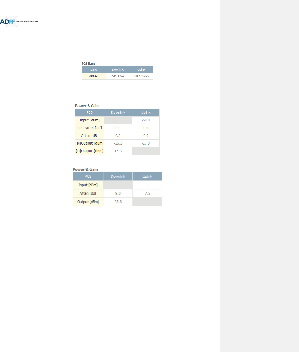
Advanced RF Technologies, Inc.
84
8.2.2.6.1 Band
Display the spectrum that is being used. The band column displays the bandwidth that has been used. The
downlink column displays the center frequency of the used downlink band. The uplink column displays the center
frequency of the used uplink band.
Figure 8-29 PCS Band Information (Status – Remote Module)
8.2.2.6.2 Power & Gain (Admin/User)
Display the Downlink output, Downlink/Uplink Attenuation, and Uplink Input/output.
Figure 8-30 Power & Gain (Admin)
Figure 8-31 Power & Gain (User)
xAdmin
oInput [dBm]: Displays the RF input level for Uplink only for the Remote Module.
oALC Atten [dB]: The amount of attenuation used when ALC is activate.
oAtten [dB]: The amount of attenuation manually set by the user.
o[M]Output [dBm]: Output power of RF transceiver (1st stage amplification).
o[H]Output [dBm]: Output power of downlink HPA (2nd stage amplification).
xUser
oInput [dBm]: Displays the RF input level for Uplink only for the Remote Module.
oAtten [dB]: The amount of attenuation manually set by the user.
oOutput [dBm]: Displays the total composite output power.
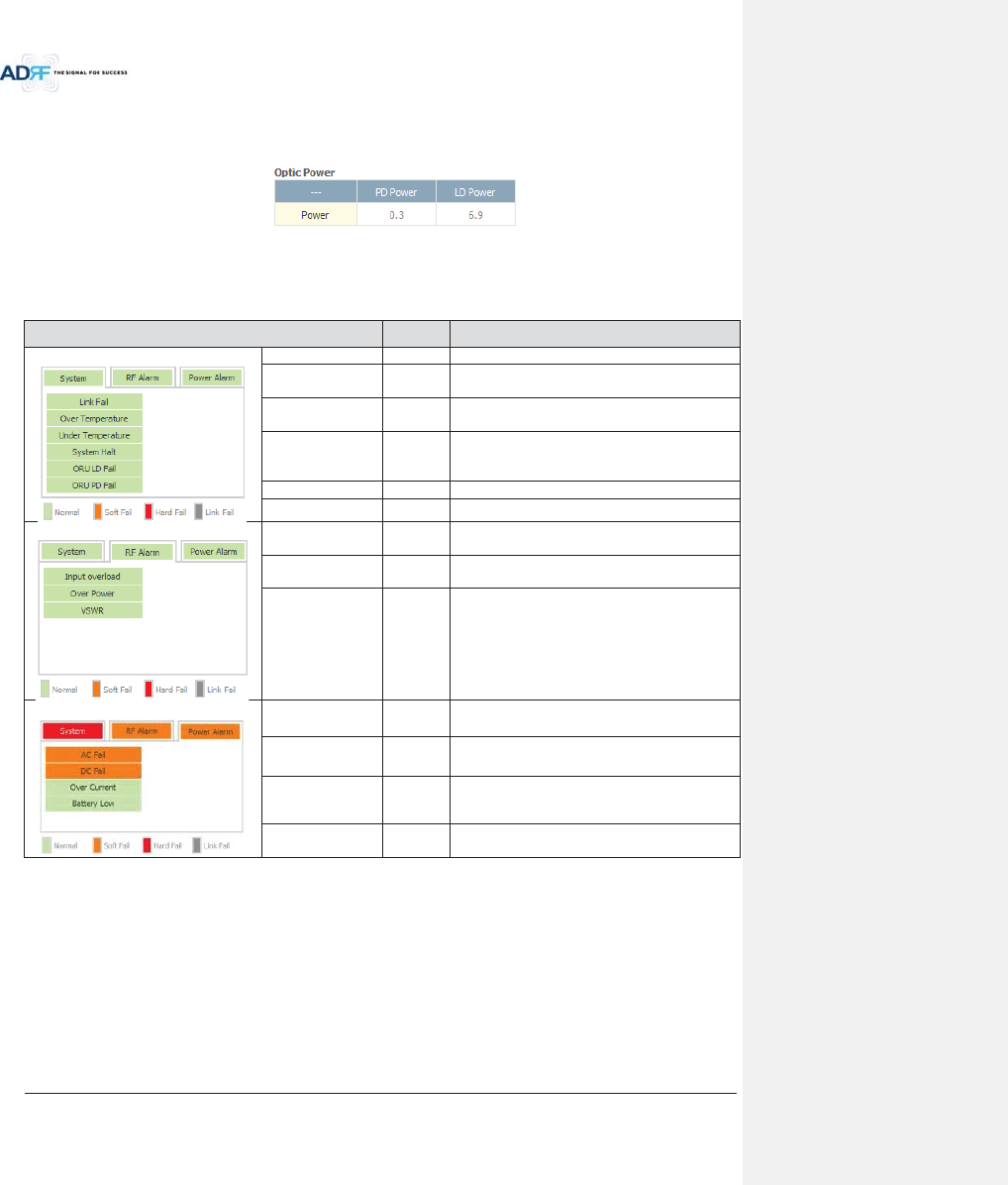
Advanced RF Technologies, Inc.
85
8.2.2.6.3 Optic Power (Master-RU Only)
Display the LD Power and PD Power of optic module inside the Master RU.
Figure 8-32 Optic Power (Status – Master HRU only)
8.2.2.6.4 Operating Status
Table 8-13 Operating Status (Status – Remote Module)
Alarm
Severity
Description
System
Link Fail
Soft Fail
No communication with NMS.
Over Temperature
Hard Fail
/ Soft Fail
Temperature is higher than the threshold level for
over temperature alarm.
Under
Temperature
Soft Fail
Temperature is lower than the threshold level for
under temperature alarm.
System Halt
Hard Fail
System halt on either the Master HRU or Slave
RU. System halt occurs when a hard fail alarm
fails to clear after 10 checks.
ORU LD Fail
Soft Fail
LD Fail present in the Master RU’s optic unit.
ORU PD Fail
Soft Fail
PD Fail present in the Master RU’s optic unit.
RF Alarm
Input Overload
Hard Fail
Uplink input signal is higher than the defined
threshold.
Over Power
Hard Fail
/ Soft Fail
Downlink output signal is higher than the defined
threshold by user.
VSWR
Soft Fail
Triggered when power is being reflected back to
the system, typically due to a loose connector.
Power Alarm
AC Fail
Soft Fail
AC power is not operating within parameters.
DC Fail
Soft Fail
DC power is not operating within parameters.
Over Current
Hard Fail
Total current of HRU is higher than the threshold
level for over current alarm.
Battery Low
Soft Fail
Voltage of battery connected to HE PSU is lower
than the defined threshold.
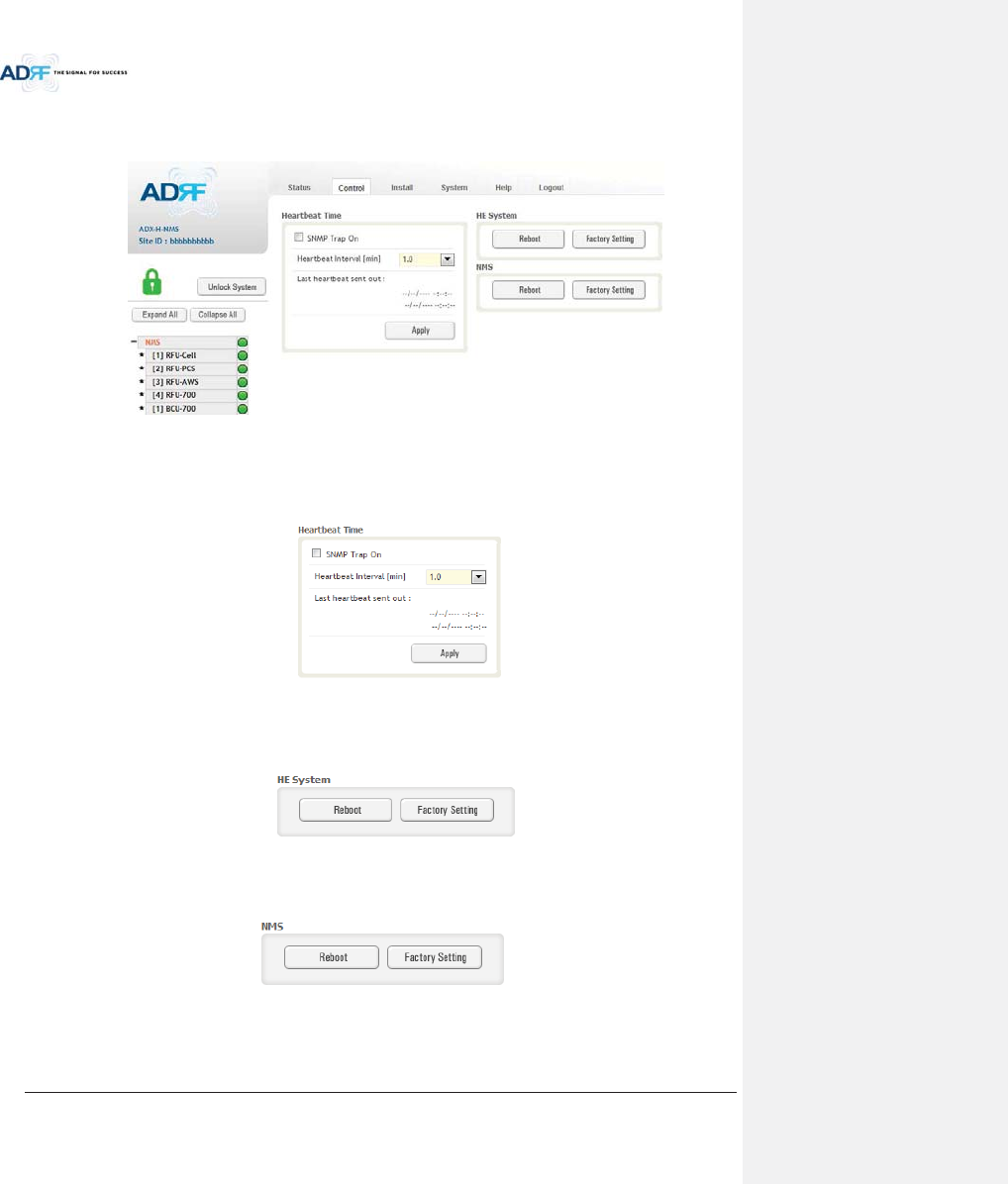
Advanced RF Technologies, Inc.
86
8.2.3 Control Tab
8.2.3.1 Control – NMS
Figure 8-33 Control - NMS
8.2.3.1.1 Heartbeat Time
Allows the user to enable or disable SNMP traps from being sent out and also specify the Heartbeat interval.
Time and date stamps of the last 2 heartbeats will be displayed in the “Last heartbeat sent out” section.
Figure 8-34 Heartbeat (Control – NMS)
8.2.3.1.2 HE System
Allows the user to perform a HE system reboot or HE full system factory settings
Figure 8-35 HE System Reboot & Factory Setting (Control – NMS)
8.2.3.1.3 NMS System
Allows the user to perform a NMS Unit reboot or NMS factory settings
Figure 8-36 NMS System Reboot & Factory Setting (Control – NMS)
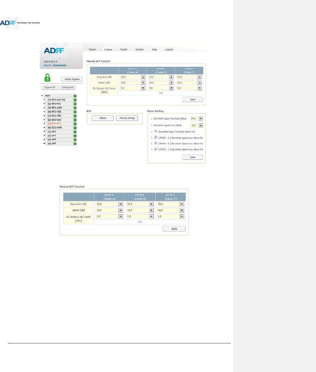
Advanced RF Technologies, Inc.
87
8.2.3.2 Control – BCU
Figure 8-37 Control – BCU
8.2.3.2.1 Manual ATT Control
Figure 8-38 Control – BCU Manual ATT Control
xDownlink: Allows the user to manually adjust the DL attenuation levels for each RF path. Adjusting
these settings is not recommended since it will change the power ratios set by the user.
xUplink: Allows the user to manually adjust the UL attenuation levels for each RF path. Adjusting these
settings is not recommended, unless additional attenuation is needed on the UL path.
xDL Output ALC Level: Allows the user to manually set the DL Output ALC Levels for each RF path.
Adjusting these settings is not recommended since it will change the power ratios set by the user.
These settings are automatically set by the system during the BCU commissioning process. This
section also displays the composite DL Output ALC Level which is the value that can be used to
commission the RFU.
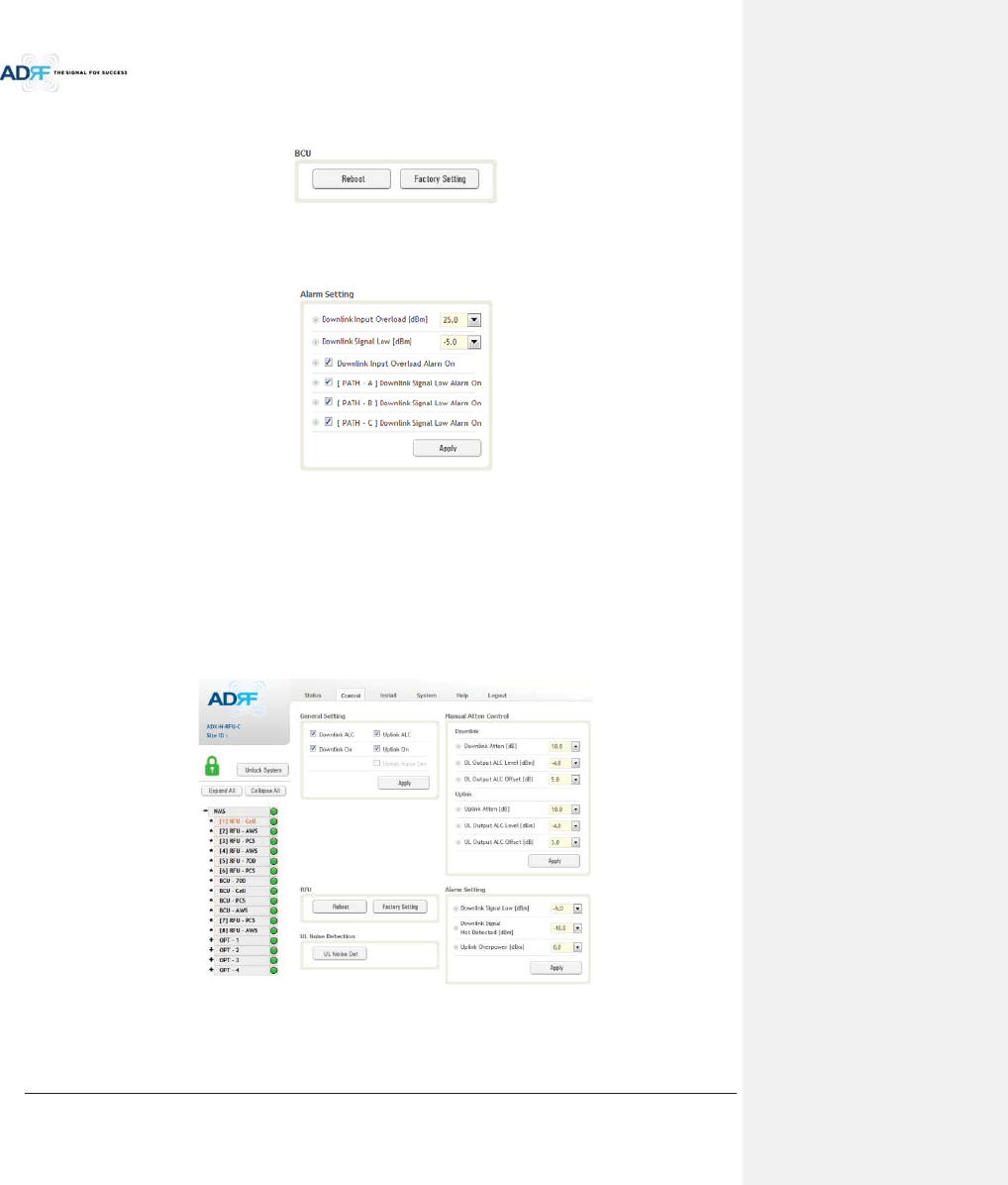
Advanced RF Technologies, Inc.
88
8.2.3.2.2 Reboot / Factory Setting
Allows the user reboot or restore factory settings of the BCU.
Figure 8-39 Control – BCU Reboot/Factory Setting
8.2.3.2.3 Alarm Setting
Figure 8-40 Control – BCU Alarm Setting
xDownlink Input Overload: Allows the user to specify the level at which the DL Input Overload alarm is
triggered. Values range from 0 dBm to +25 dBm.
xDownlink Signal Low: Allows the user to specify the level at which the DL Signal Low alarm is triggered.
Values range from -10 dBm to +20 dBm.
xDownlink Input Overload Alarm On: Allows to user to enable or disable the Input Overload Alarm
x[Path – A/B/C] Downlink Signal Low Alarm On: Allows the user to enable or disable the DL Signal Low
alarm for each RF path.
8.2.3.3 Control – RFU
Figure 8-41 Control - RFU
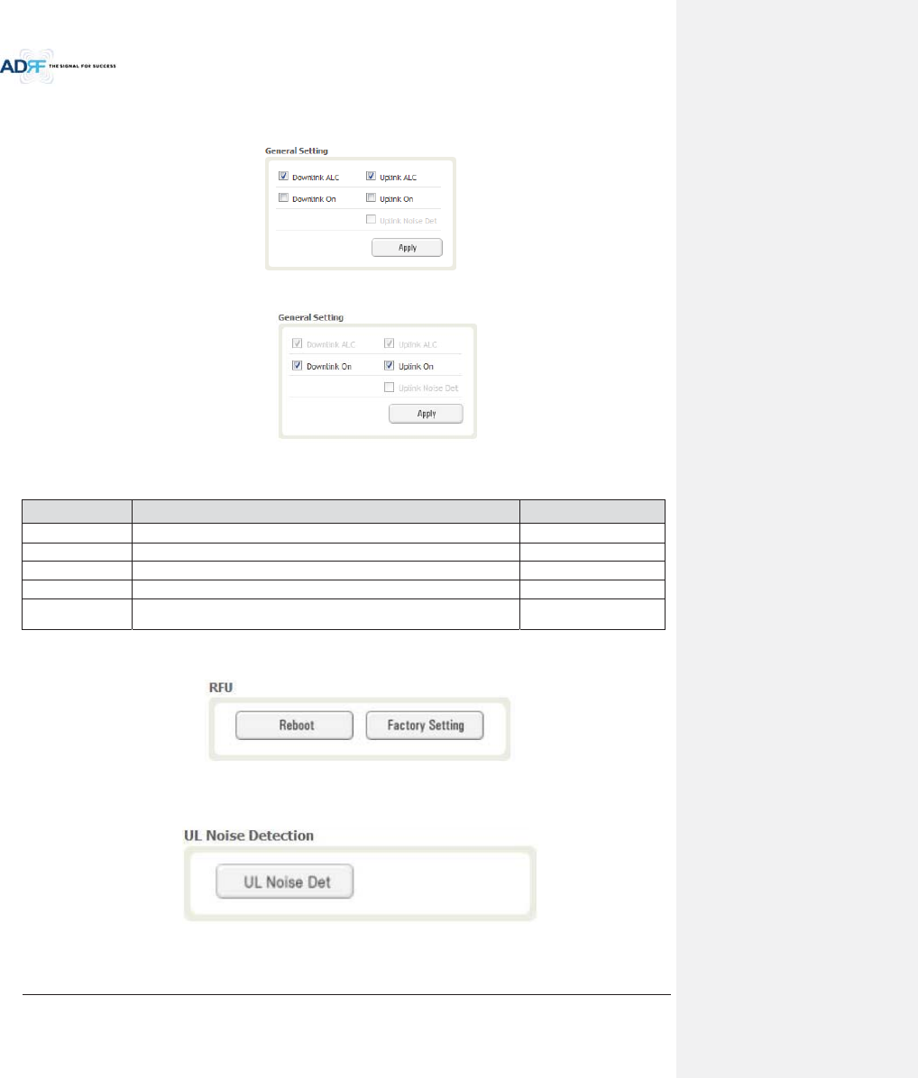
Advanced RF Technologies, Inc.
89
8.2.3.3.1 General Setting
To enable any of the settings, click on the checkbox and click the Apply button.
Figure 8-42 General Setting (Control – RFU) (Admin)
Figure 8-43 General Setting (Control – RFU) (User)
Table 8-14 Description for General Setting
Name Description Available Accounts
Downlink ALC
Enables or disables Downlink ALC
Administrator
Uplink ALC
Enables or disables Uplink ALC
Administrator
Downlink ON
Enables or disables the RFU Downlink path
Administrator, User
Uplink ON
Enables or disables the RFU Uplink path
Administrator, User
Uplink Noise Det
Displays if the module is turned on or off due to the UL Noise Detection
Routine
Administrator
8.2.3.3.2 Reboot / Factory Setting
Allows the user reboot or restore factory settings of the RFU.
Figure 8-44 Reboot & Factory Setting (Control – RFU)
8.2.3.3.3 Uplink Noise Detection (Admin Only)
Figure 8-45 UL Noise Detection (Control – RFU)
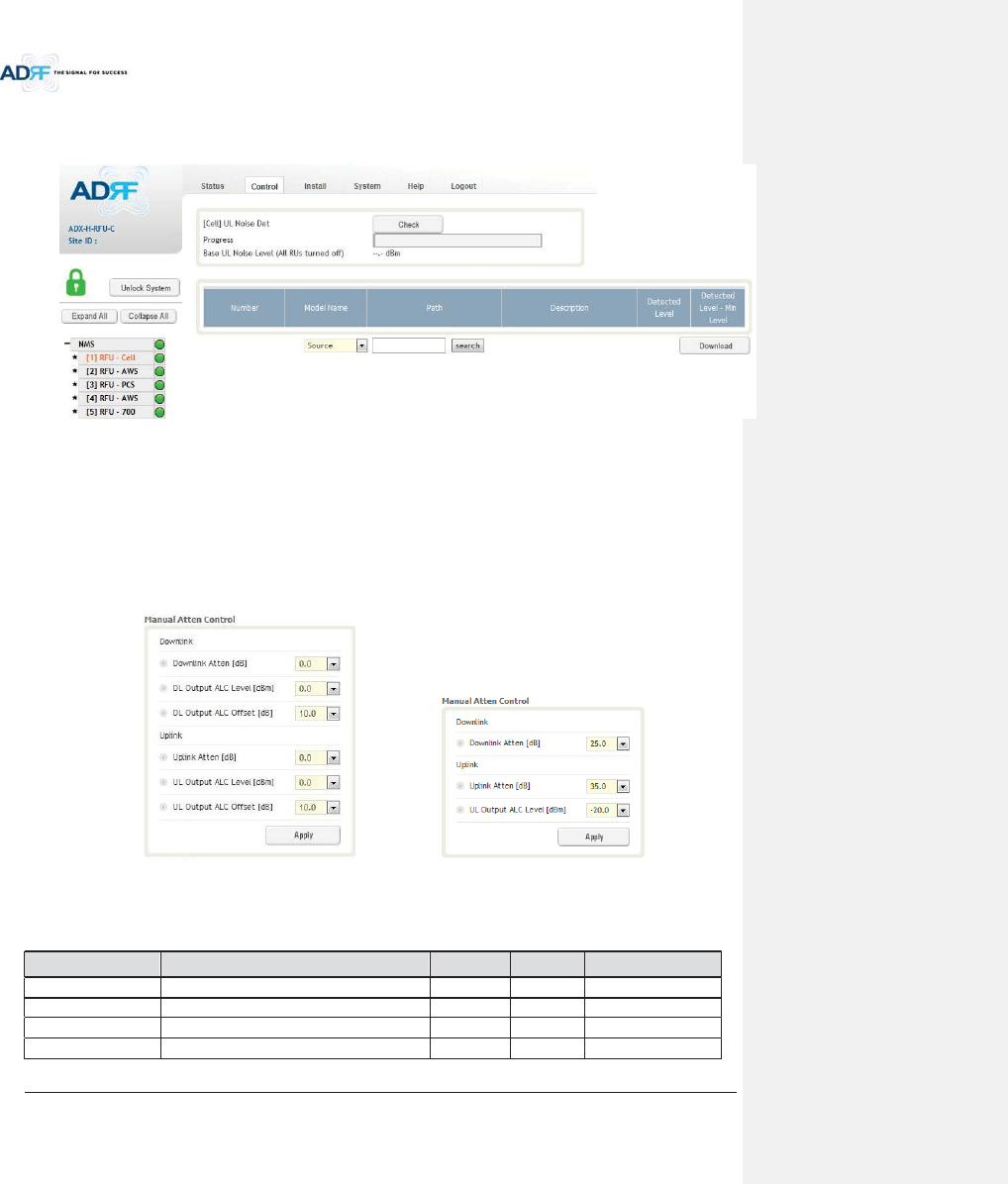
Advanced RF Technologies, Inc.
90
The “UL Noise Det” button will take you to the UL Noise Detection page which will allow you to run the UL Noise
Detection routine.
Figure 8-46 UL Noise Detection - PCS band
The Auto UL noise measurement routine can be run by clicking on the Check button. After all UL noise
measurement have been taken, the levels for each UL path will be displayed and along with the difference
between minimum detect level and measured detect level.
The user will be able to see which path is generating the elevated UL noise level based on the measured detect
level and difference value.
To navigate back to the RFU control page, click on the Control tab again.
8.2.3.3.4 Manual Atten Control
(Admin) (User)
Figure 8-47 Manual Attenuator Control Setting (Control – RFU)
Table 8-15 Description for Main Gain Control Setting (Control – RFU)
Name Description Range Step Available Accounts
Downlink Atten
Downlink Attenuator to be adjusted manually
0 ~ 25dB
0.5dB
Administrator, User
Uplink Atten
Uplink Attenuator to be adjusted manually
0 ~ 35dB
0.5dB
Administrator, User
DL Output ALC Level
To set the Max output ALC level
-10 ~ 0dBm
0.5dBm
Administrator
UL Output ALC Level
To set the Max output ALC level
-20 ~ 0dBm
0.5dBm
Administrator, User
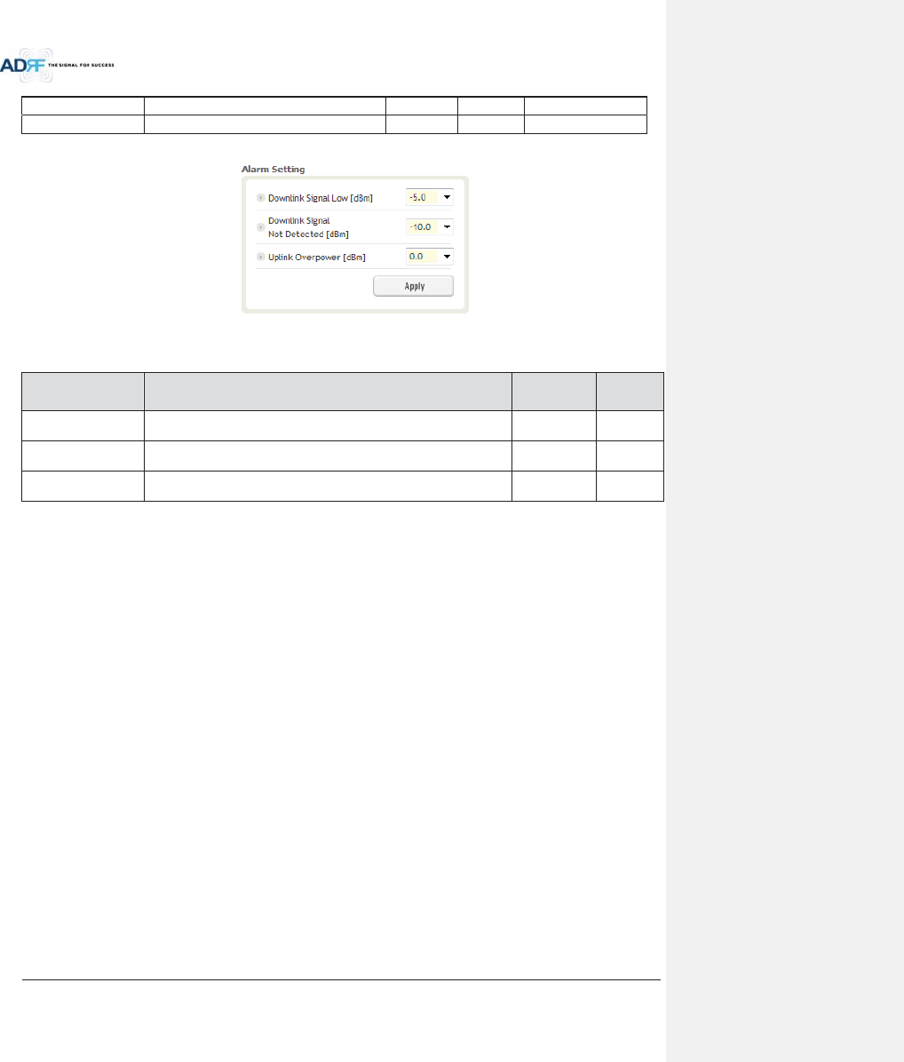
Advanced RF Technologies, Inc.
91
DL Output ALC Offset
To set the Max output ALC Offset
-10 ~ 0dBm
0.5dBm
Administrator
UL Output ALC Offset
To set the Max output ALC Offset
-20 ~ 0dBm
0.5dBm
Administrator
8.2.3.3.5 Alarm Setting
Figure 8-48 Alarm Threshold Setting (Control – RFU)
Table 8-16 Description for Alarm Threshold Setting (Control – RFU)
Name Description Range
Default
threshold
Downlink Signal Low
Allows the user to specify the minimum incoming DL input signal level
before triggering a “Downlink Signal Low” soft-fail alarm.
-10 ~ 20dBm
-5dBm
Downlink Signal Not
Detected
Allows the user to specify the minimum incoming DL input signal level
before triggering a “Downlink Signal Not Detected” soft-fail alarm.
-10 ~ 20dBm
-10dBm
Uplink Over Power
Allows the user to specify the how strong the output signal of uplink can
be before triggering an “Uplink Over Power” Hard Fail alarm.
-20 ~ 0dBm
0dBm
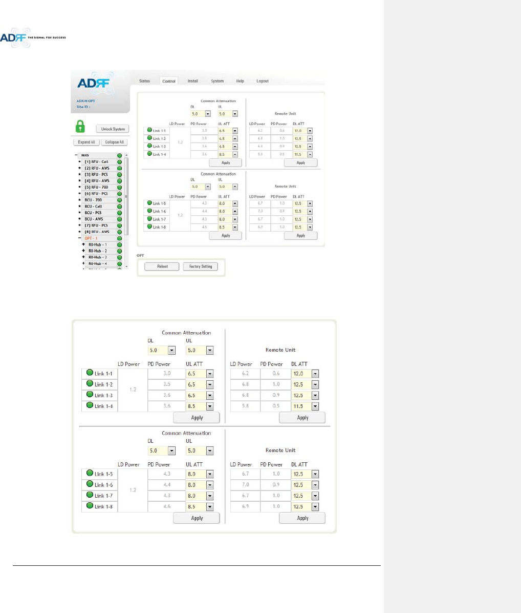
Advanced RF Technologies, Inc.
92
8.2.3.4 Control – ODU
Figure 8-49 Control – ODU
8.2.3.4.1 Optic Attenuation (Admin Only)
Figure 8-50 Optic Attenuation – ODU
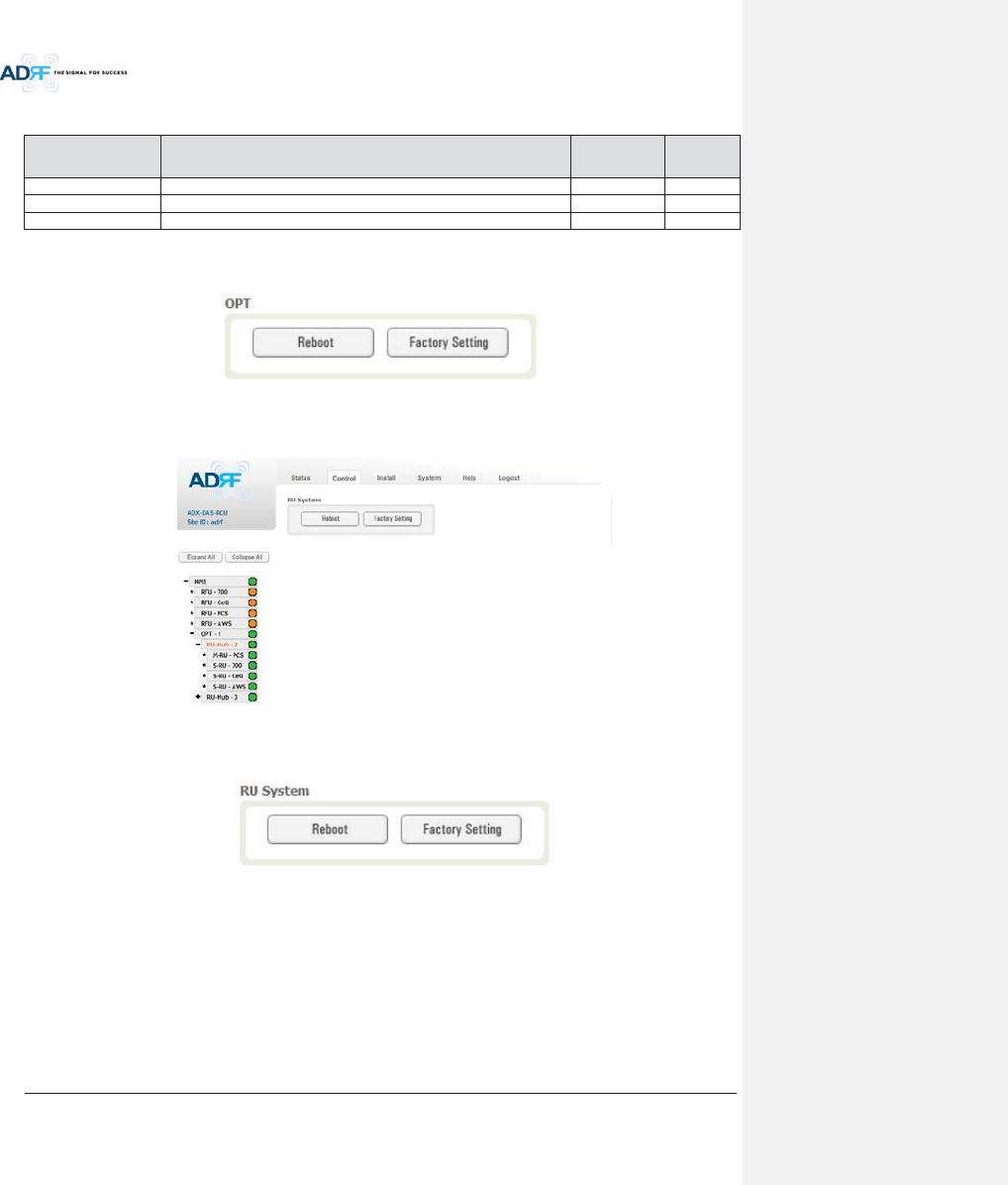
Advanced RF Technologies, Inc.
93
Table 8-17 Description for Optic Attenuation (Control – ODU)
Name Description Range
Default
threshold
DL/UL common ATT
Allows the user to control overall optic DL/UL path gain.
0 ~ 30dB
5dB
DL ATT
Used to compensate DL optic loss.
0 ~ 13dB
13dB
UL ATT
Used to compensate UL optic loss.
0 ~ 13dB
13dB
8.2.3.4.2 Reboot/Factory Setting
Allow the user to perform ODU reboot or ODU factory settings.
Figure 8-51 Reboot & factory Setting (Control – ODU)
8.2.3.5 Control – RH Hub
Figure 8-52 Control – HRU Hub
8.2.3.5.1 Reboot/Factory Setting
Allows the user to perform HRU Hub reboot or HRU Hub factory settings
Figure 8-53 Reboot & Factory Setting (Control – HRU Hub)
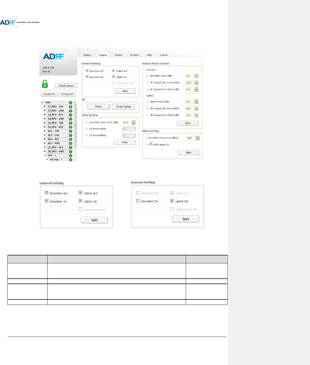
Advanced RF Technologies, Inc.
94
8.2.3.6 Control – Remote Module (Master or Slave RU)
Figure 8-54 Control – Remote Module
8.2.3.6.1 General Setting (Admin/User)
(Admin) (User)
Figure 8-55 General Setting (Control - RU)
Table 8-18 Description for General Setting (Control - RU)
Name Description Available Accounts
Downlink ALC
This setting allows you to enable or disable the downlink ALC function. When
ALC is enabled, the downlink output power will not exceed the Downlink
Output Level specified in the Manual Atten Control section.
Administrator
Downlink On
This setting allows you to enable or disable the Downlink path.
Administrator, User
Uplink ALC
This setting allows you to enable or disable the uplink ALC function. When ALC
is enabled, the Uplink output power will not exceed the Uplink Output Level
specified in the Manual Atten Control section.
Administrator
Uplink On
This setting allows you to enable or disable the Uplink path.
Administrator, User
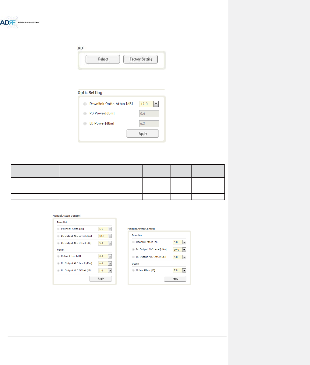
Advanced RF Technologies, Inc.
95
8.2.3.6.2 Reboot/Factory Setting
Allows the user to Reboot or restore Factory Settings on the remote module.
Figure 8-56 Reboot & factory Setting (Control - RU)
8.2.3.6.3 Optic Setting (Only Master RU) (Admin Only)
Figure 8-57 Optic Setting (Control - RU)
Table 8-19 Description for Optic Setting (Control - RU)
Name Description Range Step Available
Accounts
Downlink Optic Atten
RF attenuator to compensate the optic loss of
downlink
0~ 13.0 dB
0.5 dB
Administrator
PD Power
Incoming power level from the ODU
Administrator
LD Power
Outgoing power level to the ODU
Administrator
8.2.3.6.4 Manual Attenuator Control
(Admin) (User)
Figure 8-58 Manual Atten Control (Control - RU)
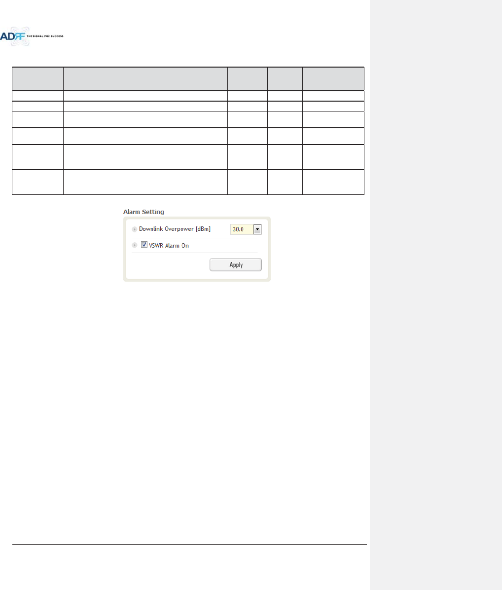
Advanced RF Technologies, Inc.
96
Table 8-20 Description for Manual Atten Control (Control - RU)
Name Description Range
Default
threshold
Available Accounts
Downlink Atten
Allows the user to specify how much attenuation to use.
0 ~ 30dB
30dB
Administrator, User
Uplink Atten
Allows the user to specify how much attenuation to use.
0 ~ 25dB
25dB
Administrator, User
DL Output ALC
Level
The remote module will prevent the downlink output
power from exceeding the specified value.
5~43dBm
43dBm
Administrator, User
UL Output ALC
Level
The system will prevent the output power to exceed the
specified value.
0 ~ 10dBm
5 or
6dBm
Administrator
DL Output ALC
Offset
When the incoming signal level increases, the system will
not adjust the gain levels until it reaches the ALC Offset
Level.
0 ~ 10dB
5dB
Administrator, User
UL Output ALC
Offset
When the incoming signal level increases, the system will
not adjust the gain levels until it reaches the ALC Offset
Level.
0 ~ 10dB
3dB Administrator
8.2.3.6.5 Alarm Setting
Figure 8-59 Alarm Setting (Control - RU)
xDL Over Power Limit: The overpower alarm threshold can be adjusted from 5~43dBm. +2dB from the DL
overpower limit will trigger a soft fail and >2dB will trigger a hard fail alarm
xVSWR Alarm ON : Enable or disables the VSWR Alarm.
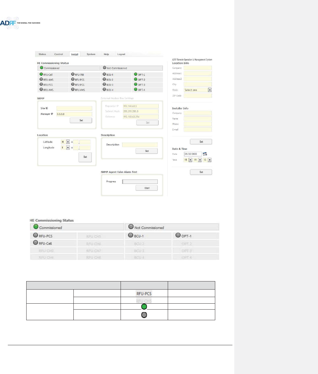
Advanced RF Technologies, Inc.
97
8.2.4 Install Tab
8.2.4.1 Install – NMS
Figure 8-60 Install - NMS
8.2.4.1.1 HE Commissioning Status
Figure 8-61 HE Commissioning Status (Install – NMS)
Table 8-21 Description for HE Commissioning Status (Install – NMS)
Status Display Description
Installed Status Physically Installed
Text is black
Physically Not-Installed
Text is gray
Commissioning Status
Success
Green
Fail or not
commissioned
Gray
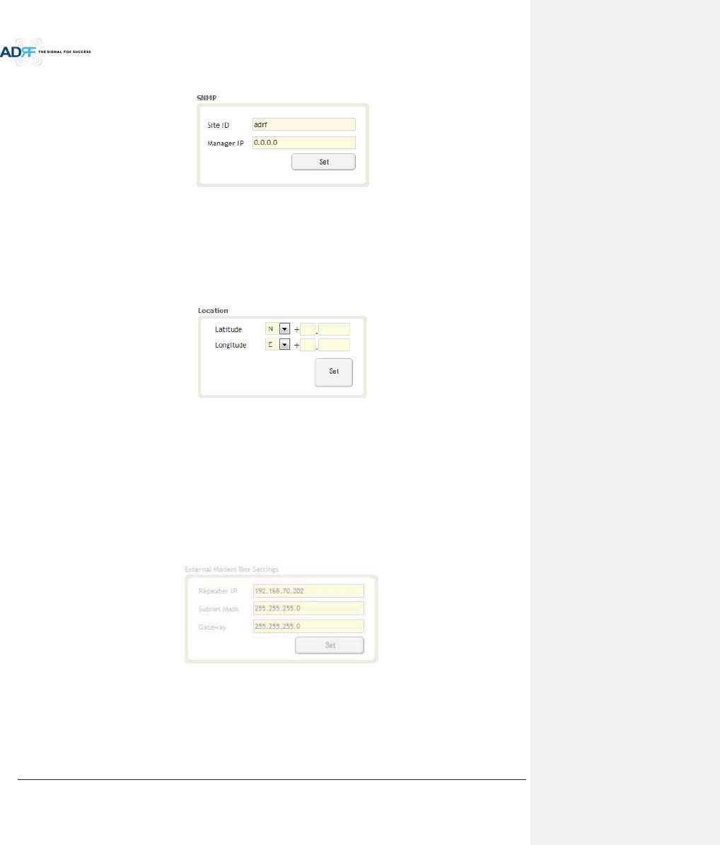
Advanced RF Technologies, Inc.
98
8.2.4.1.2 SNMP
Figure 8-62 SNMP (Install – NMS)
The SNMP section allows you to specify the Site ID and Manager IP. The Site-ID is the code that is used to
identify a particular module. The Manager IP field is where the user inputs the IP address of the NOC system that
is being used to monitor the SNMP traps.
8.2.4.1.3 Location
This section allows the user to input the latitude and the longitude of the repeater.
Figure 8-63 Location Setting (Install – NMS)
xSelect N or S from the dropdown menu for Latitude
xSelect E or W from the dropdown menu for Longitude
xInput the first 3 numbers of the latitude/longitude in the text area after the “+” and before the “.”
xInput the last 6 numbers of the latitude/longitude in the text area after the “.”
8.2.4.1.4 External Modem Box Settings
This section allows the user to specify an alternative IP, Subnet Mask, and Gateway settings. These settings
are enabled when the Host/Remote switch is set to the Remote position.
Figure 8-64 External Modem Box Setting (Install – NMS)
8.2.4.1.5 Description
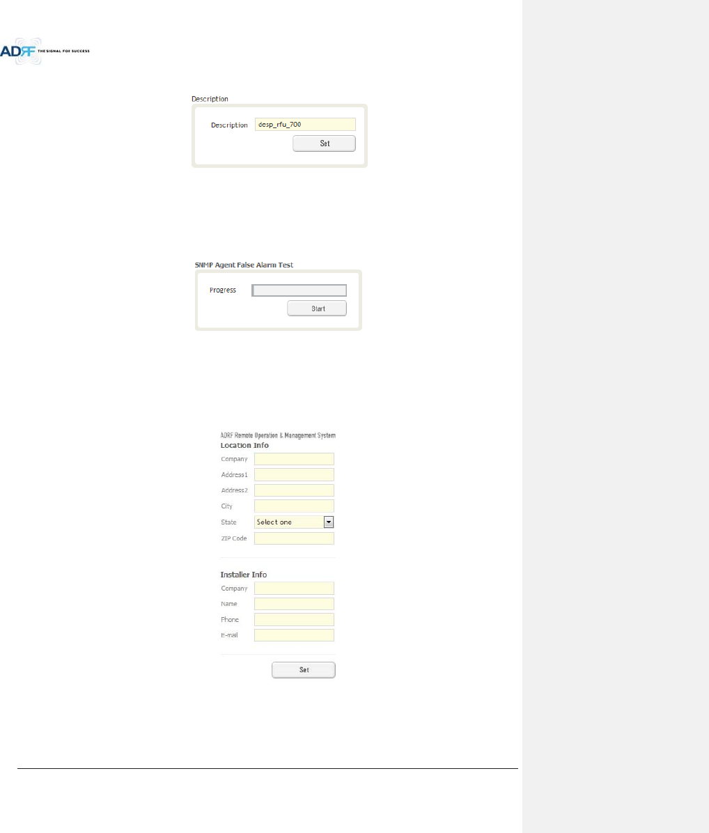
Advanced RF Technologies, Inc.
99
This section allows the user to save the description of NMS.
Figure 8-65 Description (Install – NMS)
8.2.4.1.6 SNMP Agent False Alarm Test
This section allows the user to generate both soft and hard fail alarms. After alarms are generated, the NOC
can poll the ADX to see if alarms are present. All alarms generated during this test are false alarms.
Figure 8-66 SNMP Agent False Alarm Test (Install – NMS)
8.2.4.1.7 Location Info / Installer Info
This section allows the user to specify the address of the repeater and also the information of the installer.
Figure 8-67 Location Info / Installer Info (Install – NMS)
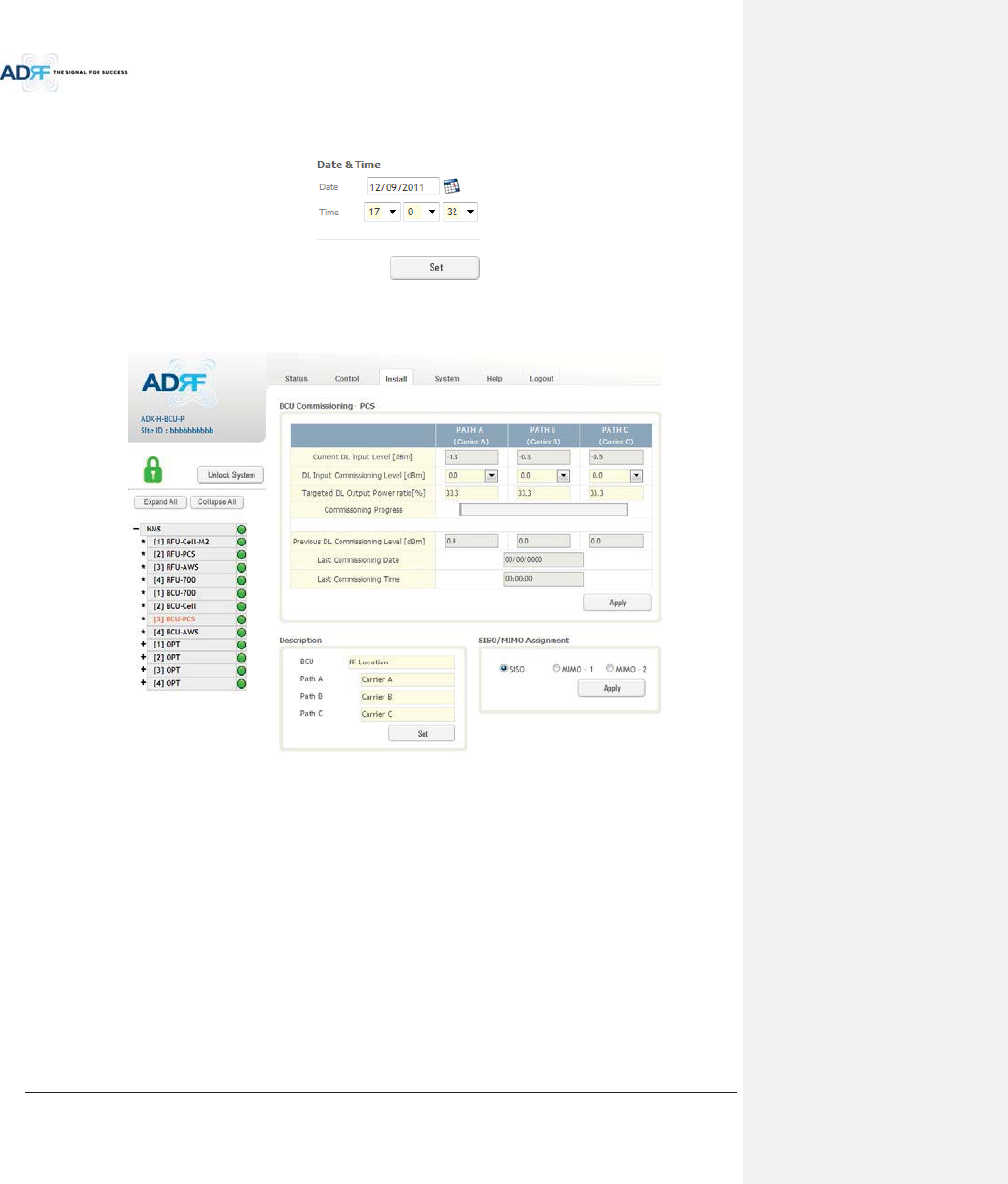
Advanced RF Technologies, Inc.
100
8.2.4.1.8 Date & Time
This section allows the user to specify the current date and time.
Figure 8-68 Date & Time Setting (Install – NMS)
8.2.4.2 Install – BCU
Figure 8-69 Install – BCU
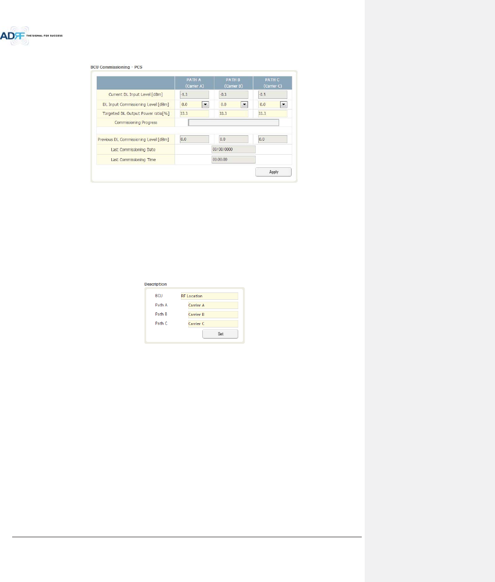
Advanced RF Technologies, Inc.
101
8.2.4.2.1 BCU Commissioning
Figure 8-70 Install – BCU Commissioning
xCurrent DL Input Level:
xDL Input Commissioning Level:
xTargeted DL Output Power Ratio:
xCommissioning Progress:
xPrevious DL Commissioning Level:
xLast Commissioning Date:
xLast Commissioning Time:
8.2.4.2.2 Description
Figure 8-71 Install – BCU Description
xBCU: This section allows the user to set the description of BCU.
xPath A/B/C: Allows the user to specify a name for each RF path. The names of each RF path will
appear in the column headers.
8.2.4.3 Install – RFU
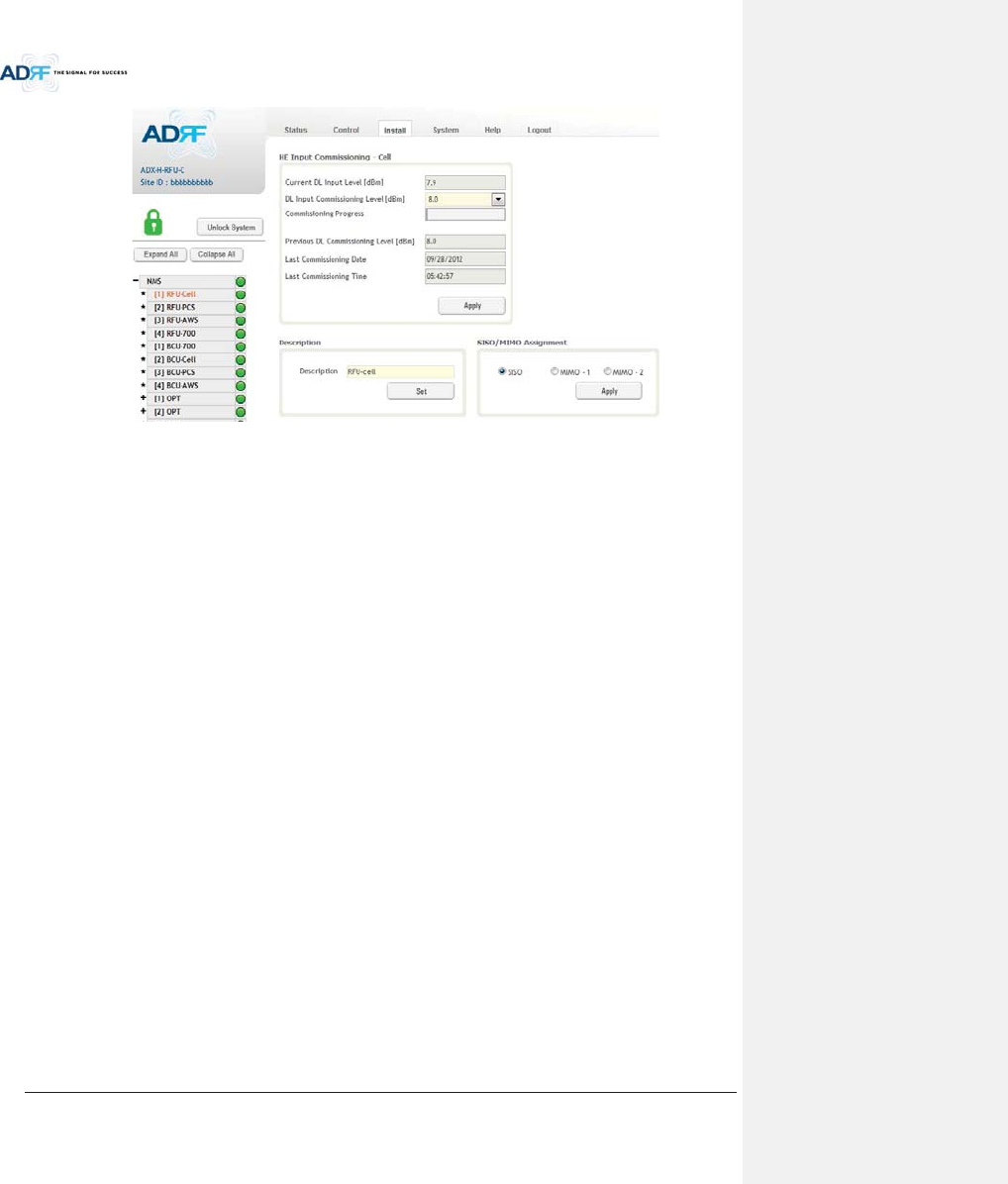
Advanced RF Technologies, Inc.
102
Figure 8-72 Install - RFU
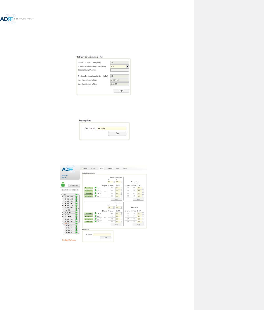
Advanced RF Technologies, Inc.
103
8.2.4.3.1 RFU Commissioning
This section allows the user to perform RFU commission. To perform RFU commissioning, select a DL Input
Commissioning Level from the dropdown menu and click Apply. The commissioning progress is displayed on the
Commissioning Progress bar. Any errors, warnings, and messages will appear via a popup window. Please refer to
the ADX Installation Guide to determine the proper RFU commissioning levels.
Figure 8-73 RFU Commissioning (Install – RFU)
8.2.4.3.2 Description
This section allows the user to set the description of RFU.
Figure 8-74 Description (Install – RFU)
8.2.4.4 Install – ODU
Figure 8-75 Install – ODU
8.2.4.4.1 Optic Commissioning
This section will allow the user to perform any optic compensation if it is necessary. The Commissioning
button will turn orange if optic compensation is needed.
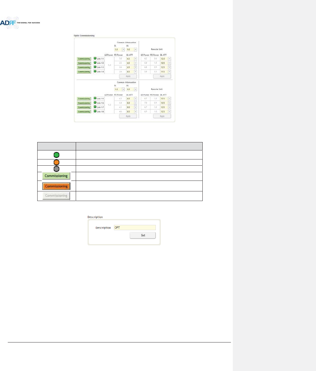
Advanced RF Technologies, Inc.
104
Figure 8-76 Optic control (Control – ODU)
Table 8-22 Description for Optic control (Control – ODU)
Display & Control
Description
Optic loss is less than 5dBo
Optic loss is more than 5dBo
Not connected to a RU
No optic loss compensation
is needed.
Optic loss compensation is needed.
Not connected to a RU
8.2.4.4.2 Description
This section allows the user to save the description of ODU.
Figure 8-77 Description (Install – ODU)
8.2.4.5 Install – HRU Hub
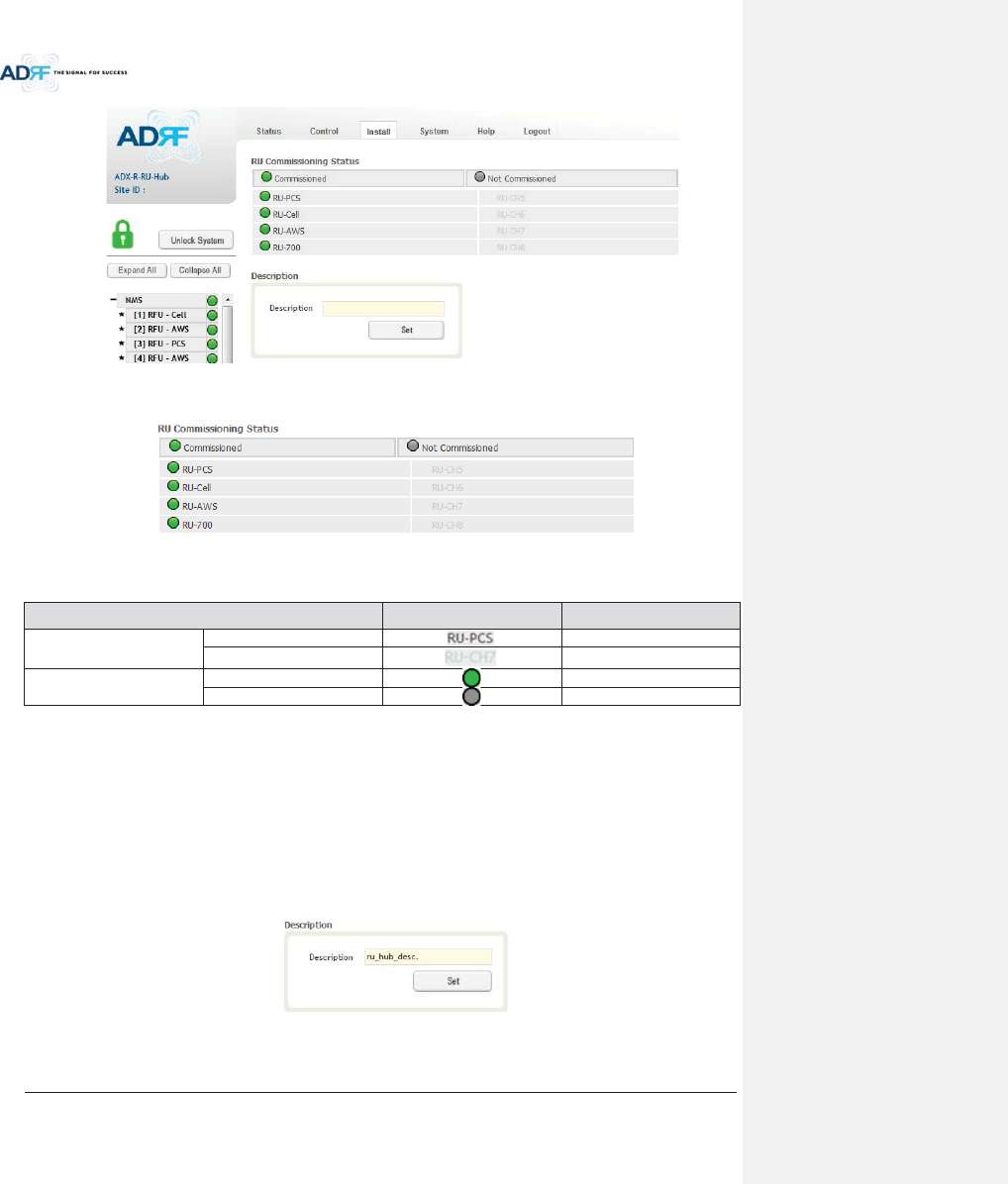
Advanced RF Technologies, Inc.
105
Figure 8-78 Install-RU Hub
8.2.4.5.1 RU Commissioning Status
Figure 8-79 RU Commissioning Status (Install-RU Hub)
Table 8-23 Description for HRU Commissioning status
Status Display Description
Installed Status
Physically Installed
Text is black
Physically Not-Installed
Text is gray
Commissioning Status
Success
Green
Fail or not commissioned
Gray
8.2.4.5.2 Description
This section allows the user to save the description of HRU Hub.
Figure 8-80 Description (Install-RU Hub)
8.2.4.6 Install – Remote Module (Master or Slave RU)
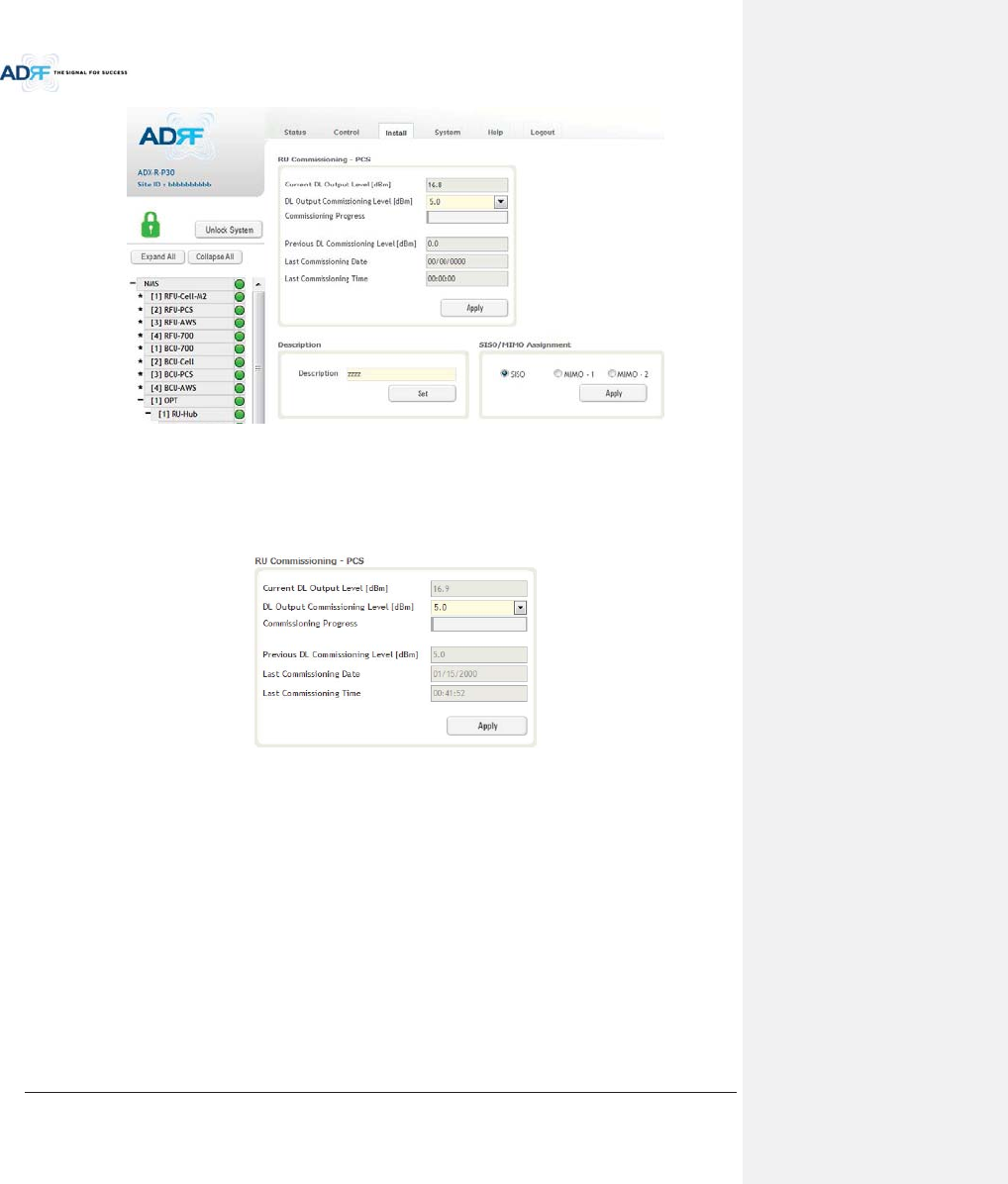
Advanced RF Technologies, Inc.
106
Figure 8-81 Install-Remote Module
8.2.4.6.1 RU Output Commissioning
This section allows the user to perform HRU commission. To perform HRU commission, select a DL Output
Commissioning Level from the dropdown menu and then click Apply. The commissioning progress is displayed on
the Commissioning Progress bar. Any errors, warnings, and messages will appear via a popup window.
Figure 8-82 RU Output Commissioning (Install-RU)
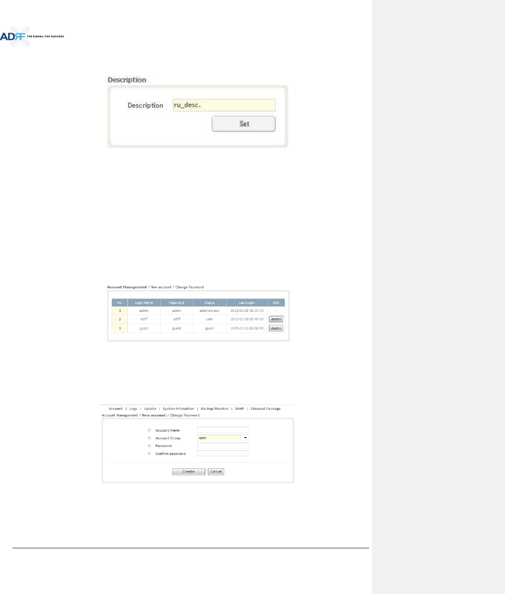
Advanced RF Technologies, Inc.
107
8.2.4.6.2 Description
This section allows the user to save the description of remote module.
Figure 8-83 Description (Install-Remote Module)
8.2.5 System
The System tab allows the user to perform firmware updates, upload closeout packages, view any changes to
the system, backup existing configuration, and add/remove user accounts, and change the login credentials of the
Administrator.
8.2.5.1 System: Account
8.2.5.1.1 System: Account - Account Management (Admin Only)
The Account Management section allows the Administrator to delete any user/guest account. Please note
that the Account Management section is only available if you are logged into the system as the Administrator. To
delete a user/guest account click on the Account Management link and under the Delete column, click on the
delete button.
Figure 8-84 Account Management
8.2.5.1.2 System: Account - New Account (Admin Only)
The New account section allows the Administrator to create a new user/guest account. Please note that the
new account section is only available if you are logged into the system as the Administrator. To create a new
user/guest account click on the new account link and fill in the fields highlighted in yellow as shown below.
Figure 8-85 New Account
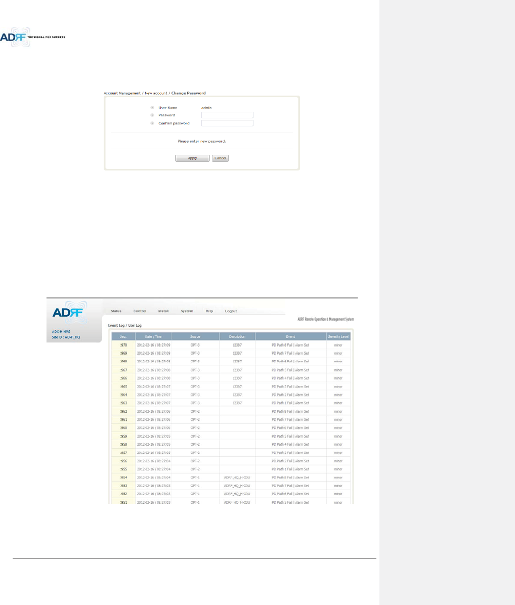
Advanced RF Technologies, Inc.
108
8.2.5.1.3 System: Account - Change Password
The Change Password section allows the current user who is logged into the system to change their login
credentials.
Figure 8-86 Change Password
8.2.5.2 System: Logs
8.2.5.2.1 System: Logs - Event Log
This section displays system events that have taken place. The Event Log displays who has made the changes,
the time and date of when the event took place, and what changes were made to the system. The System Log
tracks the following events:
xSystem Initiation
xAlarm Set
xAlarm Clear
Figure 8-87 Event Log
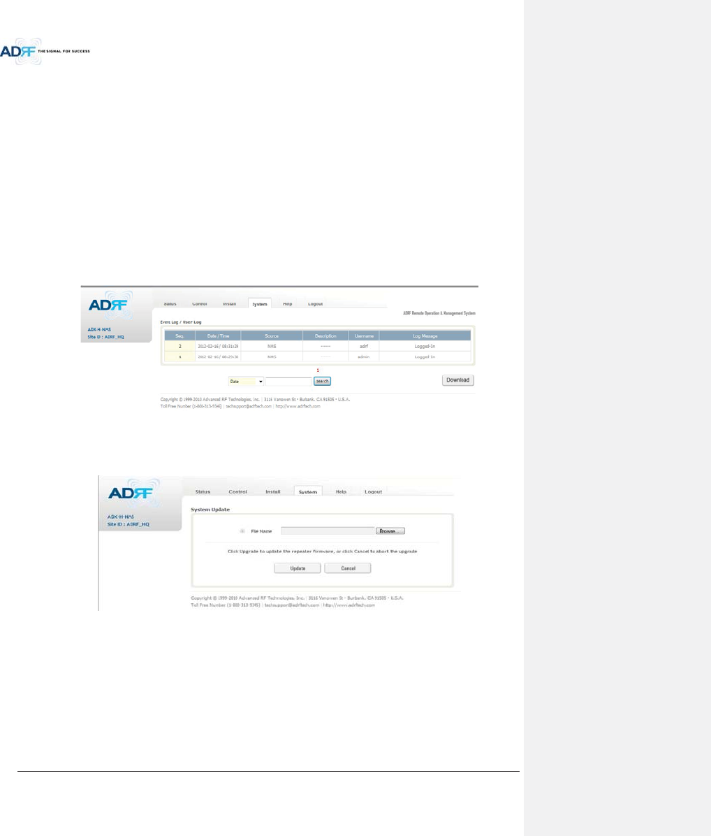
Advanced RF Technologies, Inc.
109
8.2.5.2.2 System: Logs - User Log
This section tracks user activity within the system. The User Log displays who has made the changes, the time
and date of when the event took place, and what changes were made to the system. The User Log tracks the
following items:
xLog in / Log out activity
xChanges to gain/attenuation/output values
xSystem event generated by user(firmware update, backup/resote, create/delete account)
xDAS Navigation Tree Lock/Unlock
xDescription change
xRepeater/installer information change
xSetting date/time
Figure 8-88 User Log
8.2.5.3 System: Update
xTo perform a firmware update, click on the System:Update tab and the following screen will show up.
Figure 8-89 System update
xClick on the ‘Browse’ button and locate the firmware file.
xClick on the Update button to perform the firmware update.
xOnce the firmware update is complete, the following message will appear.
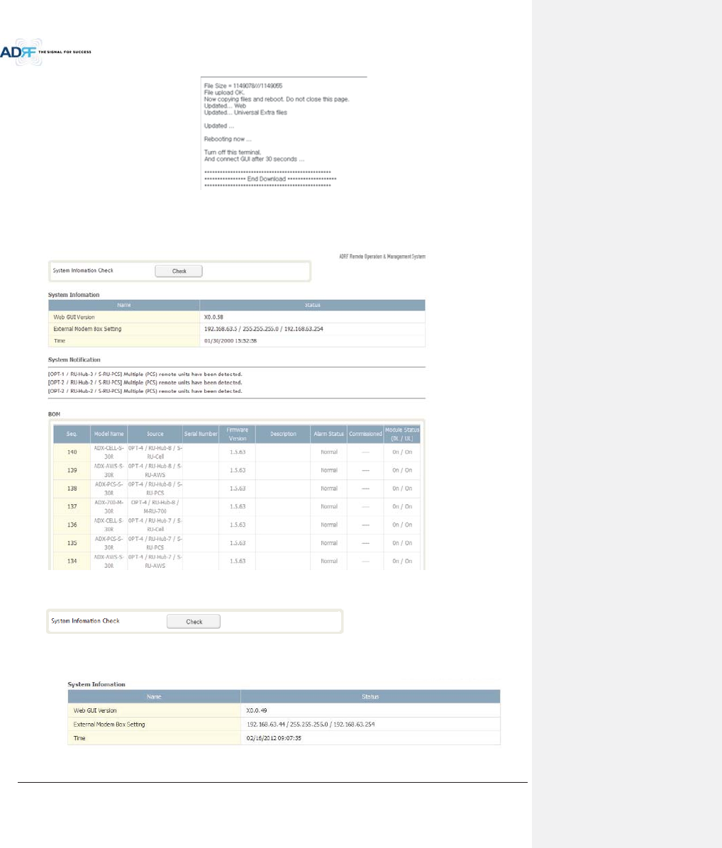
Advanced RF Technologies, Inc.
110
Figure 8-90 Message after System update is complete
8.2.5.4 System: System Information
8.2.5.4.1 System: System Information
xSystem Information Check
The System Information Check button will check the ADX configuation and report possible discrepancies.
xSystem Information
This section displays the general system information of the ADX DAS.
Figure 8-91 System Information
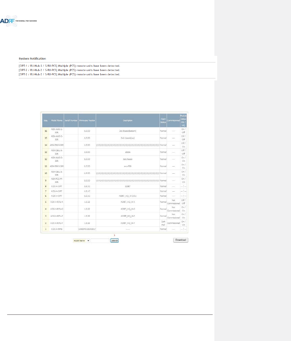
Advanced RF Technologies, Inc.
111
xSystem Notification
This section is displayed only when the following conditions are present:
- When multiple remote modules with same frequency band exist in a RU.
- When the remote module does not match with the RFU being used.
Figure 8-92 System Notification
xBOM
BOM displays all parts that are connected to the ADX-H-NMS.
The BOM can be downloaded as a CSV file by clicking the ‘Download’ button at the bottom right.
Figure 8-93 Bill of material
8.2.5.5 System: Backup/Restore
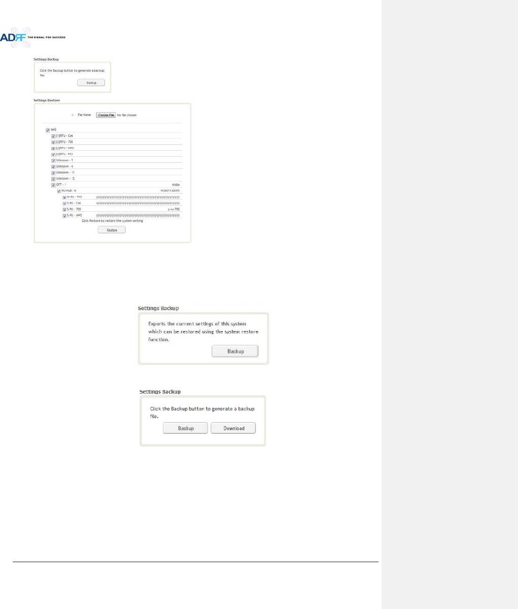
Advanced RF Technologies, Inc.
112
xSettings Backup
Clicking the Backup will create a temporary backup file stored inside of the ADX. Once the file is created, it will
need to be downloaded to a computer. A download button will appear after the backup file has been created. If
the ADX is power cycled or rebooted, then the temporary backup file will be lost. We recommend downloading
the backup file immediately after it has been created. Click on the Download button to download the backup file.
Figure 8-94 Setting Backup (Before)
Figure 8-95 Setting Backup (After)
xSetting Restore
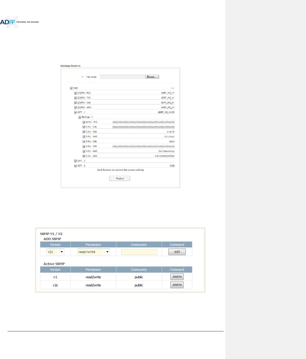
Advanced RF Technologies, Inc.
113
Restore function can be used to restore the saved settings from the backup file. Once the backup file is loaded,
the tree in the figure below will appear. Check the boxes of the modules that you would like to restore and then
click the “Restore” button at the bottom on this section.
We recommend creating a new backup file if adding or removing modules from the ADX. Discrepancies
between the backup file and the existing tree could cause restore errors.
Figure 8-96 Setting Restore
8.2.5.6 System: SNMP
xSNMP V1/V2
This section allows you to add community strings for SNMP v1 and v2.
Figure 8-97 SNMP V1/V2

Advanced RF Technologies, Inc.
114
xSNMP V3
This section allows the user to add accounts for SNMP v3.
Figure 8-98 SNMP V3
8.2.5.7 System: Closeout Package
The closeout package section will allow the user to upload documents to the ADX-H-NMS. The maximum file
size for each upload is limited to 10 MB. The total amount of space available for uploading document is 100 MB.
Please do not use this section as the primary storage location of your documents. Documents may become
unavailable if the system goes down.
Figure 8-99 System- Closeout Package
To upload documents to the module, click on the “Browse” button and locate the file that you would like to
upload, then enter in a Description of the file being uploaded. Afterwards, click on the “Add File” button to upload
the file. Below is what you will see after the file upload. To delete the file, click on the delete button located in the
last column.
Figure 8-100 System- Closeout Package after the file upload

Advanced RF Technologies, Inc.
115
8.2.6 Help
If an internet connection is available, clicking on the Help Tab will redirect the user to our Technical Support
page.
Figure 8-101 Help
8.2.7 Logout
Clicking the Logout button will log the current user off the system.
8.3 Guest Mode
When logging into the system as a guest, the guest will only have read-only privileges and will not be able to
make any changes to the system.
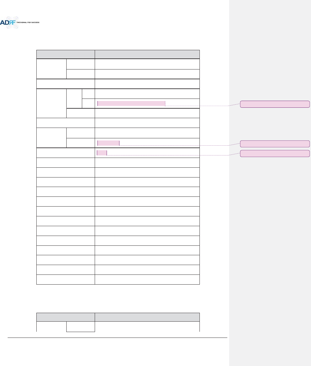
Advanced RF Technologies, Inc.
116
9. SYSTEM-WIDE SPECIFICATION (TO BE CONNECTED TO HE VIA OPTIC LINE)
9.1 PCS band
Item
Specification
Frequency
Downlink
1930
-1995MHz
Uplink
1850
-1915MHz
DL Input Range
at HE
0~25dBm
Gain
Range
DL
1
8~43dB, 0.5dB step, ATT range: 0~25dB
UL
-
5~30dB, 0.5dB step, ATT range: 0~35dB
Accuracy
0~15dB: < ±0.5dB, 15~
35dB: < ±1.0dB
Gain Flatness
< ±3.0dB
Composite
Maximum
Output Power
Downlink at
HRU
43dBm±2dB
Uplink
at HE
-
15dBm±2dB
Noise Figure @max gain
7.0
dB
VSWR
< 1:1.5
EVM
< 8%
Optical Loss
0~5dBo(with ADX
-H-ODU4)/0~10dBo(with ADX-H-ODU1)
System Delay
<2us @0dBo optic loss
Spurious
FCC, 3GPP TS 36.104, 3GPP2 C.S0010
-C
Operating Temperature
-
30-55qC
Operating Humidity
5
-90%
Dimension (W x H x D)
12.6 x 35.5 x 11.8 in
Weight
105.8 lbs.(without mounting bracket)
Cooling Method
Fan
Mount
Wall mount, Pole mount(optional)
RF Connector
DIN type female
Weather Resistance
IP
56/NEMA 4X
9.2 AWS band
Item Specification
Frequency
Downlink
2110
-2155MHz
ָ֦ [Y2]: Correction 14/05/08
ָ֦ [Y3]: Correction 14/05/08
ָ֦ [Y4]: Correction 14/05/08
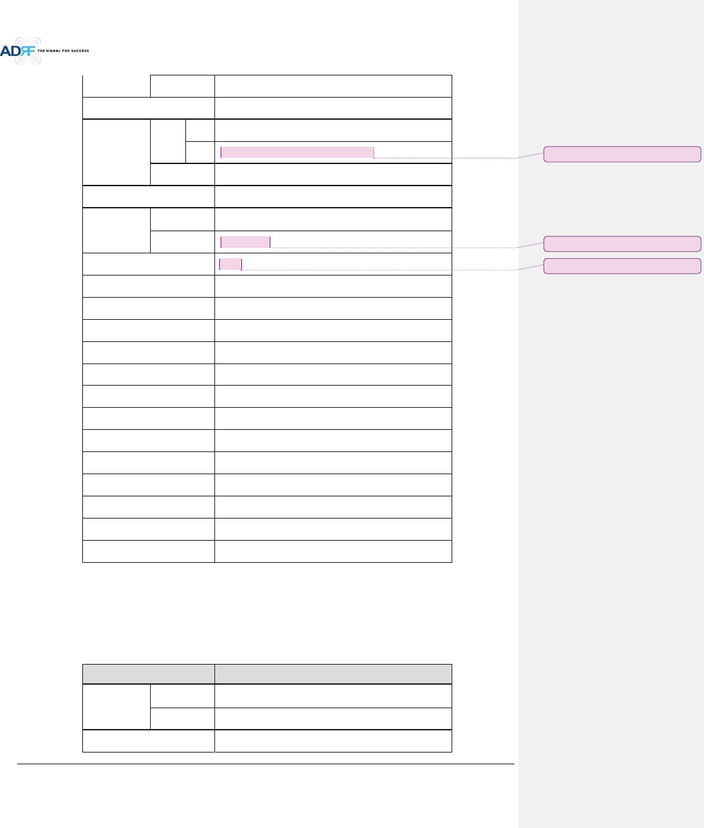
Advanced RF Technologies, Inc.
117
Uplink
1710
-1755MHz
DL Input
Range at HE
0~25dBm
Gain
Range
DL
1
8~43dB, 0.5dB step, ATT range: 0~25dB
UL
-
5~30dB, 0.5dB step, ATT range: 0~35dB
Accuracy
0~15dB: < ±0.5dB, 15~
35dB: < ±1.0dB
Gain Flatness
< ±3.0dB
Composite
Maximum
Output Power
Downlink at
HRU
43dBm±2dB
Uplink
at HE
-
15dBm±2dB
Noise Figure @max gain
7.0
dB
VSWR
< 1:1.5
EVM
< 8%
Optical Loss
0~5dBo(with ADX
-H-ODU4)/0~10dBo(with ADX-H-ODU1)
System Delay
<2us @0dBo optic loss
Spurious
FCC, 3GPP TS 36.104, 3GPP2 C.S0010
-C
Operating Temperature
-
30-55qC
Operating Humidity
5
-90%
Dimension (W x H x D)
12.6 x 35.5 x 11.8 in
Weight
105.8 lbs.(without mounting bracket)
Cooling Method
Fan
Mount
Wall mount, Pole mount(optional)
RF Connector
DIN type female
Weather Resistance
IP
56/NEMA 4X
9.3 Cellular band
Item Specification
Frequency
Downlink
869
-894MHz
Uplink
824
-849MHz
DL Input Range
at HE
0~25dBm
ָ֦ [Y5]: Correction 14/05/08
ָ֦ [Y6]: Correction 14/05/08
ָ֦ [Y7]: Correction 14/05/08
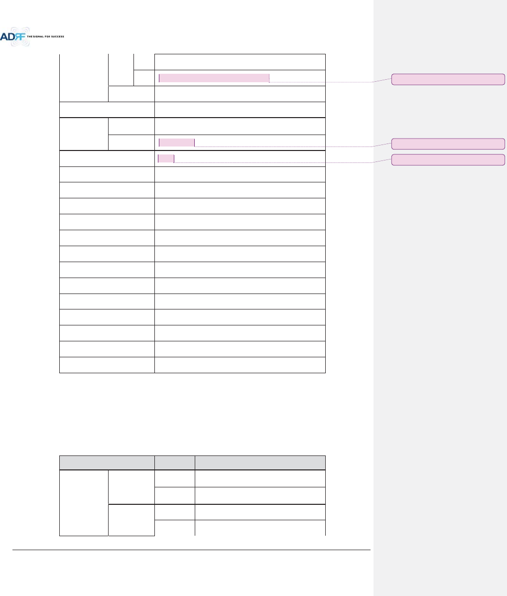
Advanced RF Technologies, Inc.
118
Gain
Range
DL
1
8~43dB, 0.5dB step, ATT range: 0~25dB
UL
-
5~30dB, 0.5dB step, ATT range: 0~35dB
Accuracy
0~15dB: < ±0.5dB, 15~
35dB: < ±1.0dB
Gain Flatness
< ±3.0dB
Composite
Maximum
Output Power
Downlink at
HRU
43dBm±2dB
Uplink
at HE
-
15dBm±2dB
Noise Figure @max gain
7.0
dB
VSWR
< 1:1.5
EVM
< 8%
Optical Loss
0~5dBo(with ADX
-H-ODU4)/0~10dBo(with ADX-H-ODU1)
System Delay
<
2us @0dBo optic loss
Spurious
FCC, 3GPP TS 36.104, 3GPP2 C.S0010
-C
Operating Temperature
-
30-55qC
Operating Humidity
5
-90%
Dimension (W x H x D)
12.6 x 35.5 x 11.8 in
Weight
105.8 lbs.(without mounting bracket)
Cooling Method
Fan
Mount
Wall mount,
Pole mount(optional)
RF Connector
DIN type female
Weather Resistance
IP
56/NEMA 4X
9.4 700 band
Item Specification
Frequency
Downlink
Lower ABC
728
-746MHz
Upper C
746
-757MHz
Uplink
Lower ABC
698
-716MHz
Upper C
776
-787MHz
ָ֦ [Y8]: Correction 14/05/08
ָ֦ [Y9]: Correction 14/05/08
ָ֦ [Y10]: Correction 14/05/08
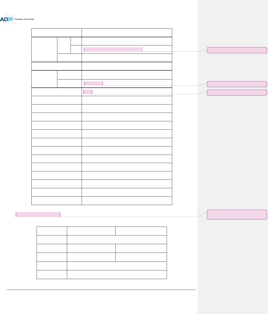
Advanced RF Technologies, Inc.
119
DL Input Range
at HE
0~25dBm
Gain
Range
DL
1
8~43dB, 0.5dB step, ATT range: 0~25dB
UL
-
5~30dB, 0.5dB step, ATT range: 0~35dB
Accuracy
0~15dB: < ±0.5dB, 15~
35dB: < ±1.0dB
Gain Flatness
< ±3.0dB
Composite
Maximum
Output Power
Downlink at
HRU
43dBm±2dB
Uplink
at HE
-
15dBm±2dB
Noise Figure @max gain
7.0
dB
VSWR
< 1:1.5
EVM
< 8%
Optical Loss
0~5dBo(with ADX
-H-ODU4)/0~10dBo(with ADX-H-ODU1)
System Delay
<2us @0dBo optic loss
Spurious
FCC, 3GPP TS 36.104, 3GPP2 C.S0010
-C
Operating Temperature
-
30-55qC
Operating Humidity
5
-90%
Dimension (W x H x D)
12.6 x 35.5 x 11.8 in
Weight
105.8 lbs.(without mounting bracket)
Cooling Method
Fan
Mount
Wall mount, Pole mount(optional)
RF Connector
DIN type female
Weather Resistance
IP
56/NEMA 4X
10. ANTENNA SPECIFICATIONS
10.1 Omni Antenna
Frequency
698
-960MHz
1710
-2690MHz
Polarization
Vertical
Gain
2dBi
3dBi
VSWR
<1.7:1
<1.5:1
Impedance
50:
Power Rating
50W
ָ֦ [Y11]: Correction 14/05/08
ָ֦ [Y12]: Correction 14/05/08
ָ֦ [Y13]: Correction 14/05/08
ָ֦ [Y14]: Add Antenna Spec.
2014/05/29
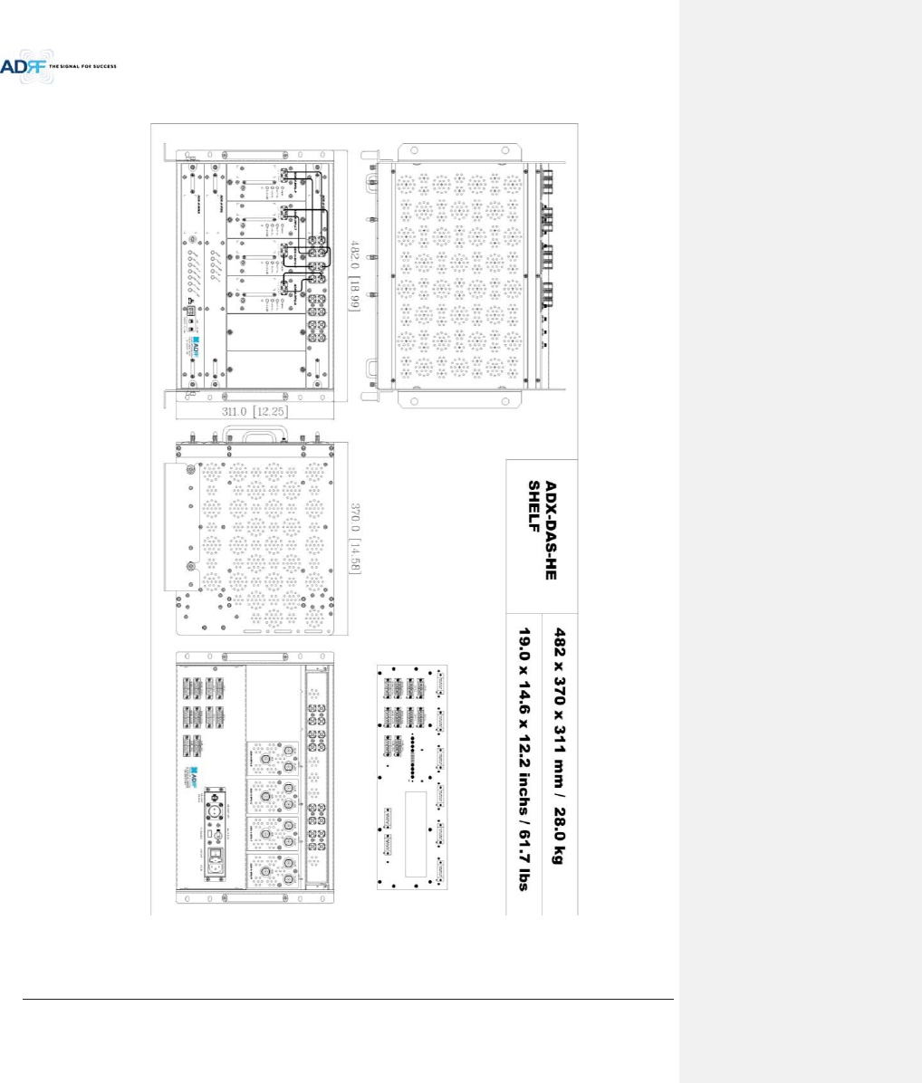
Advanced RF Technologies, Inc.
120
11. MECHANICAL DRAWING
Figure 11-1 HE Drawing
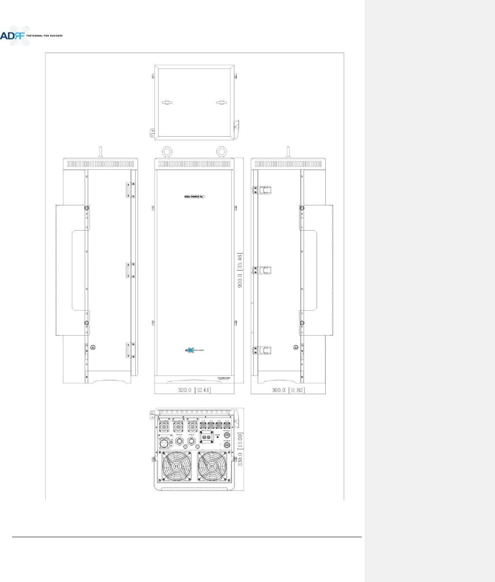
Advanced RF Technologies, Inc.
121
Figure 11-2 Master HRU Drawing