ADRF KOREA ADXV-HPR DAS (Distributed Antenna System) User Manual ADXV DAS
ADRF KOREA, Inc. DAS (Distributed Antenna System) ADXV DAS
UserManual.wiki
>
ADRF KOREA
>
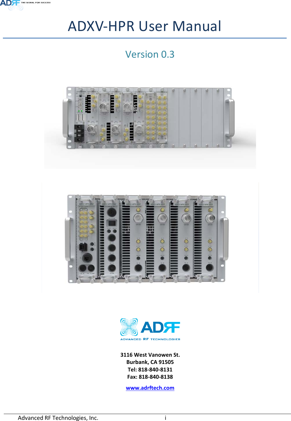
ADXV HPR User Manual
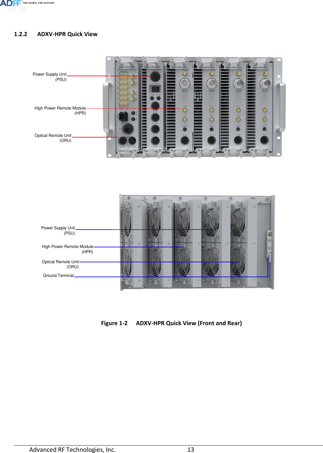
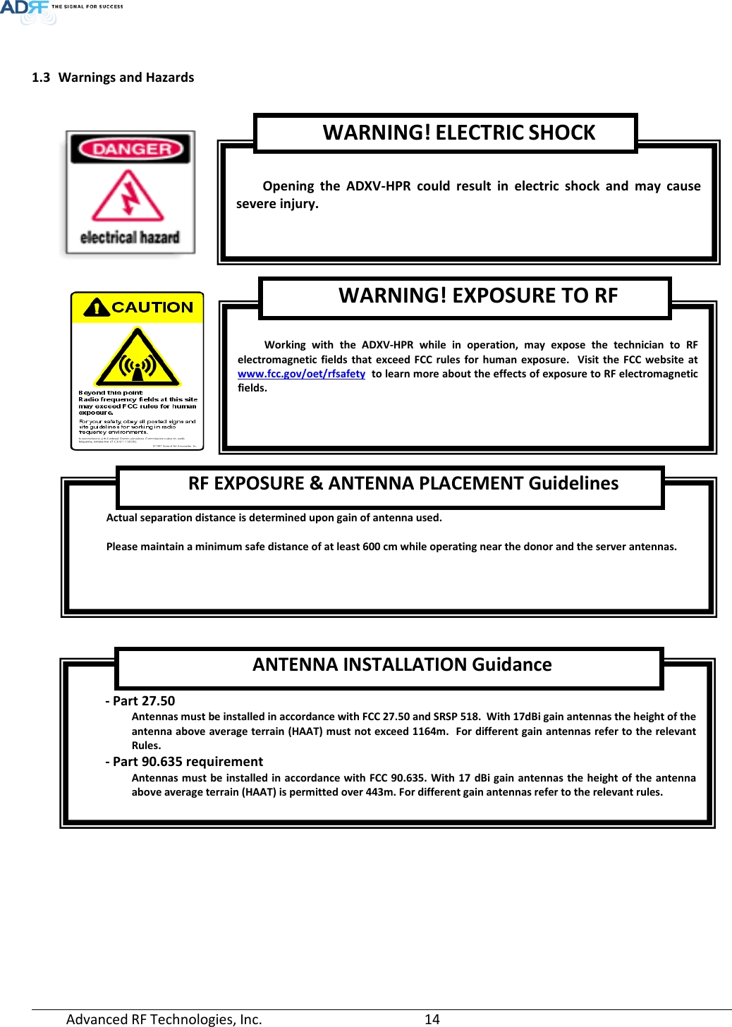
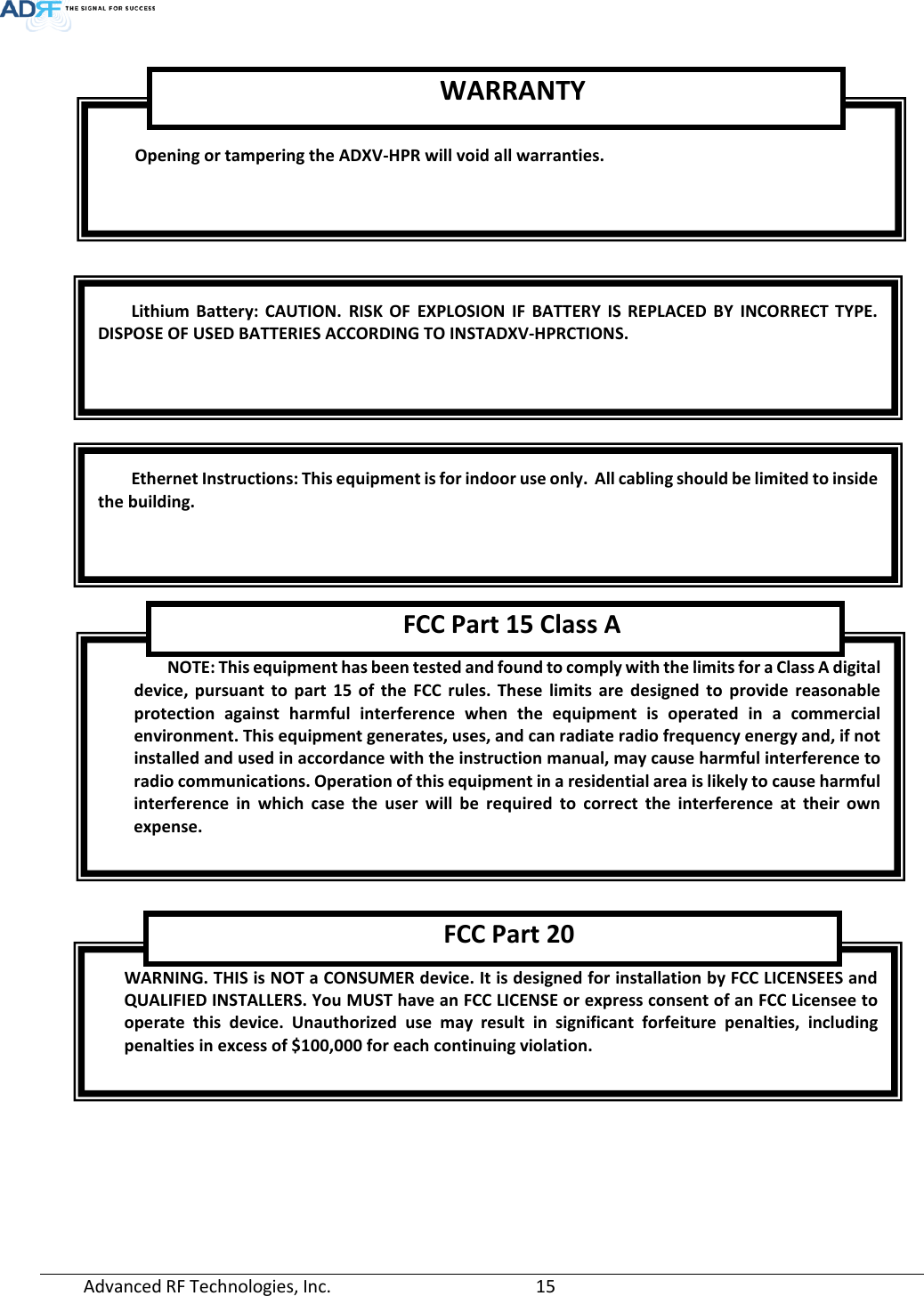
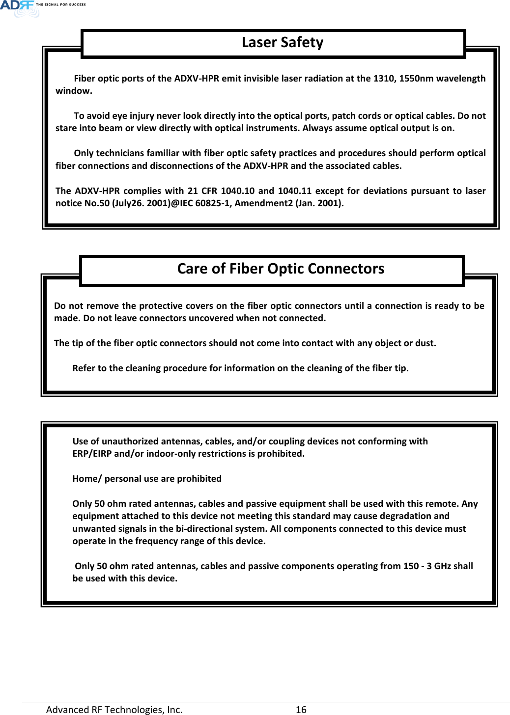
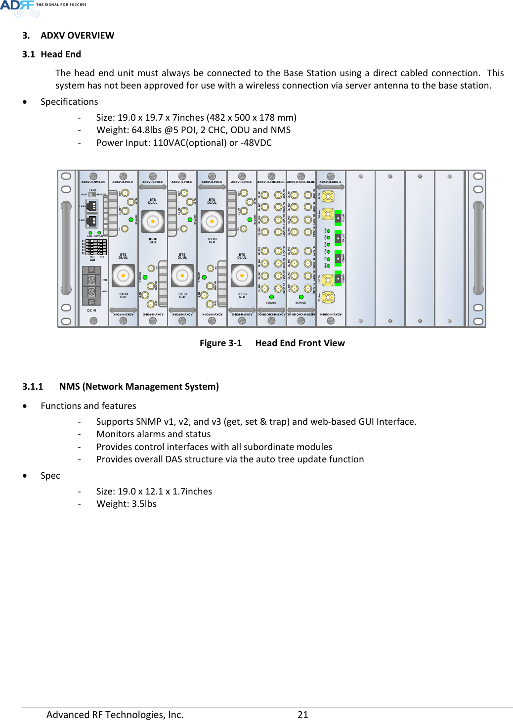
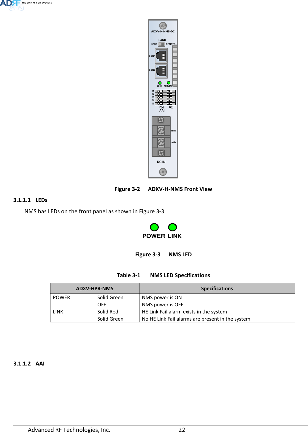
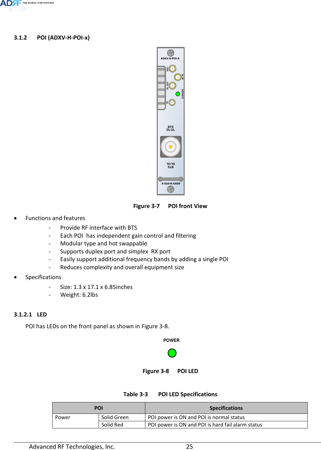
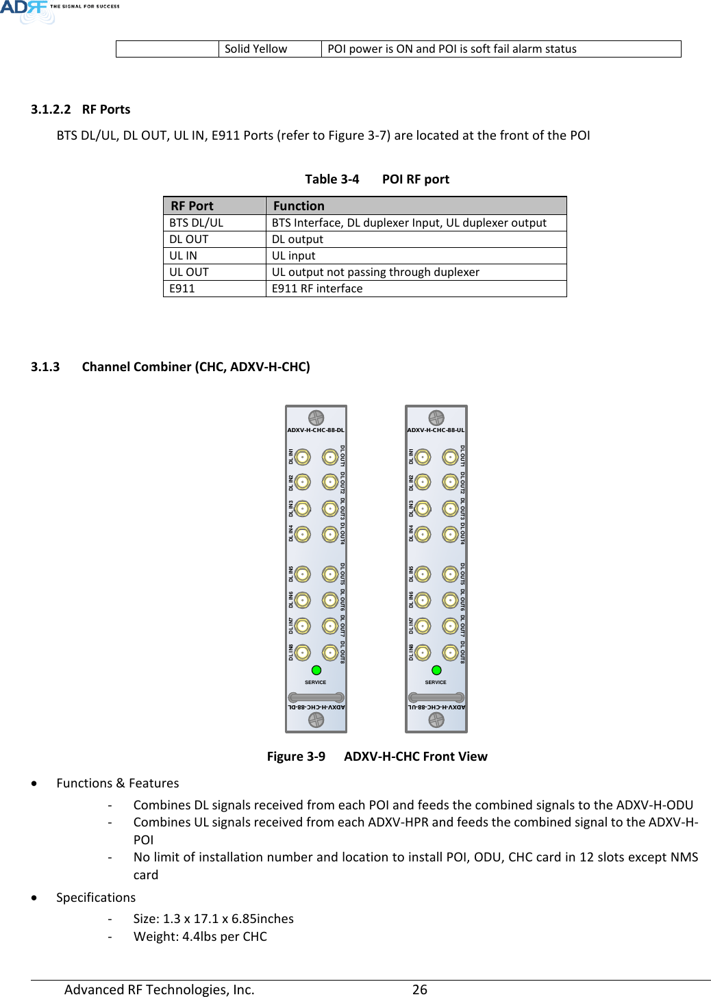
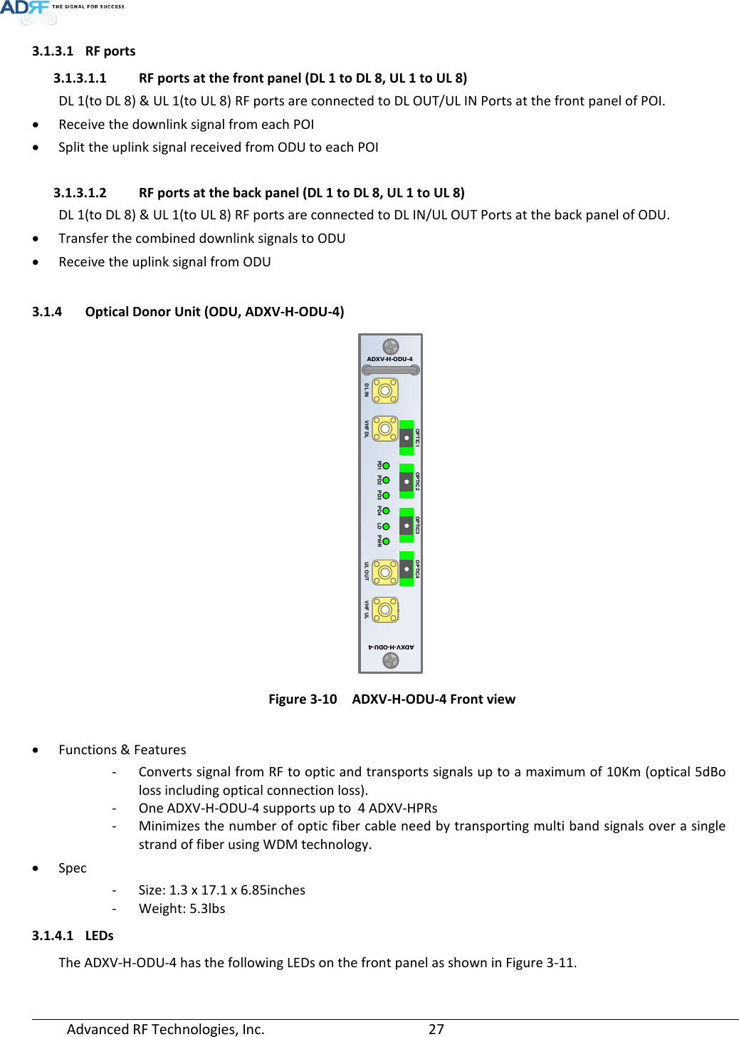
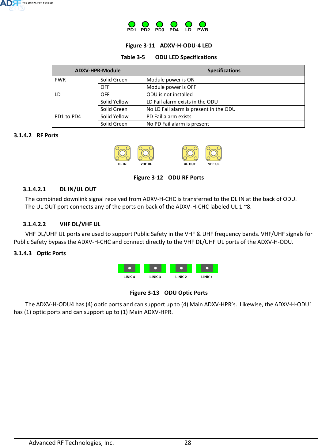
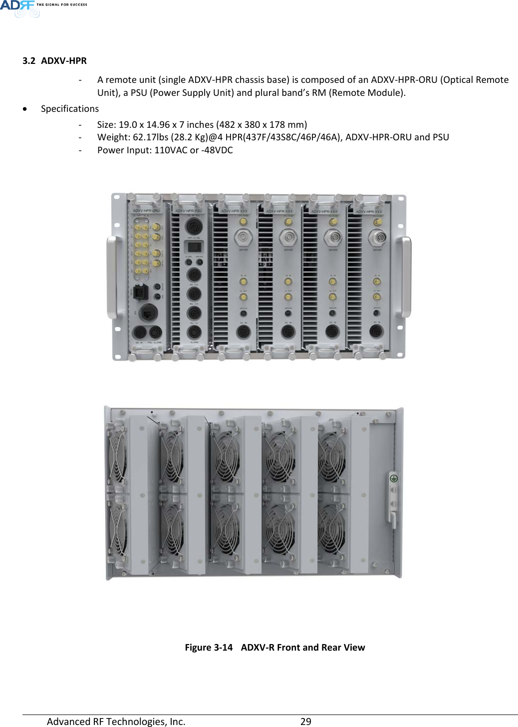
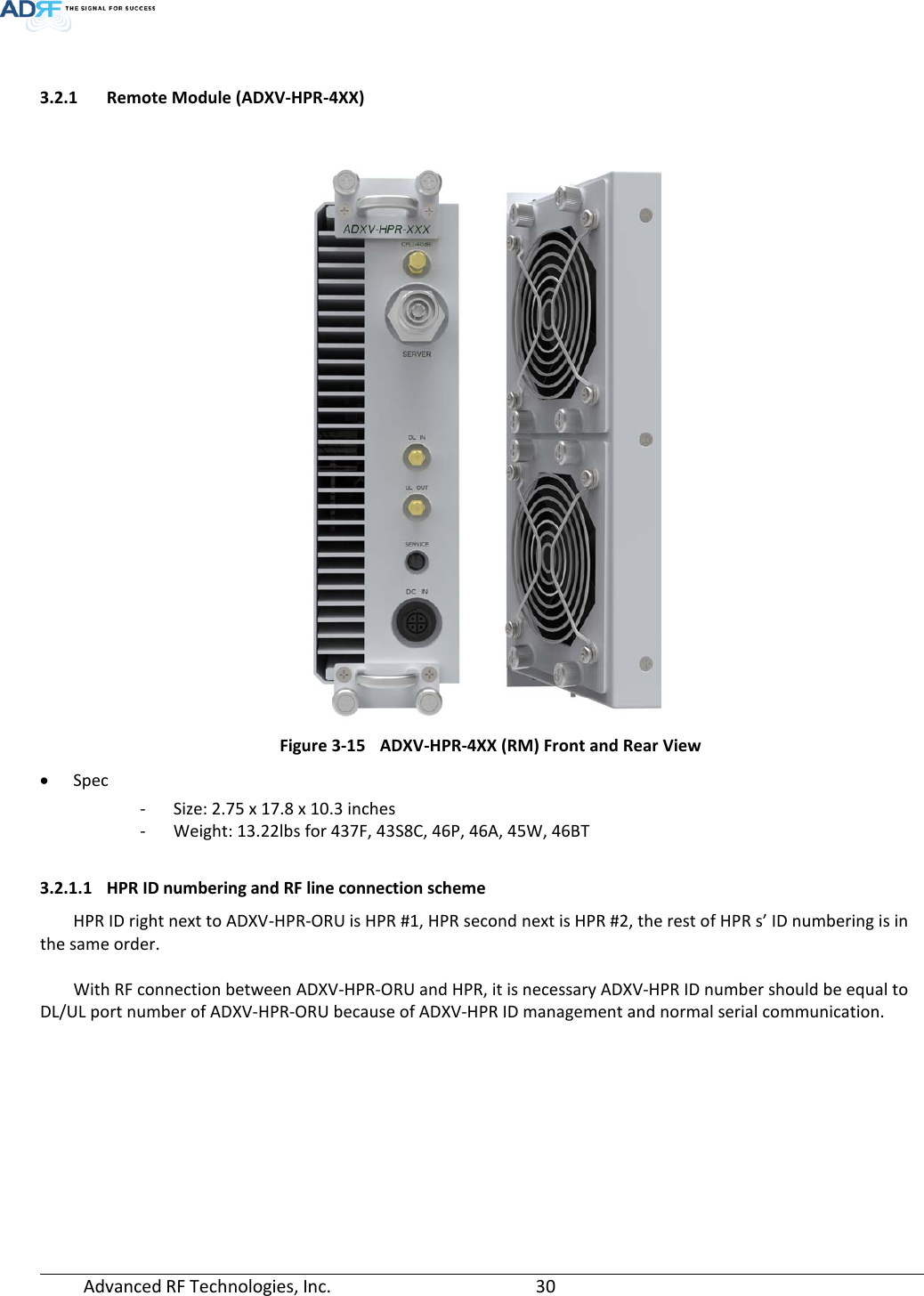
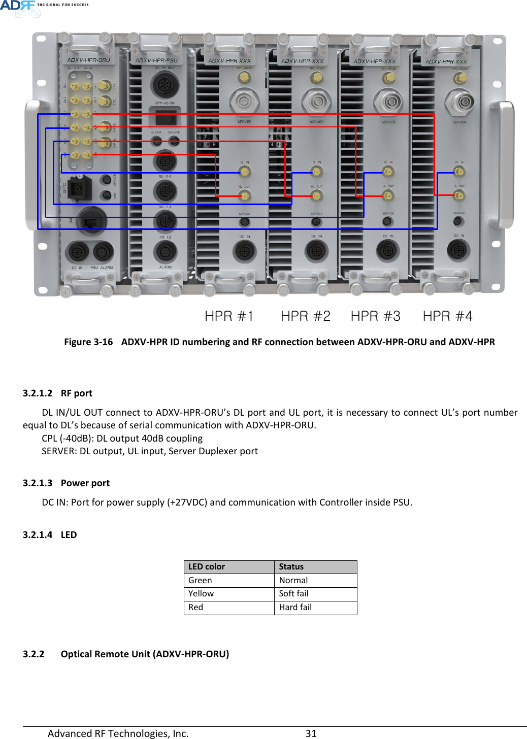
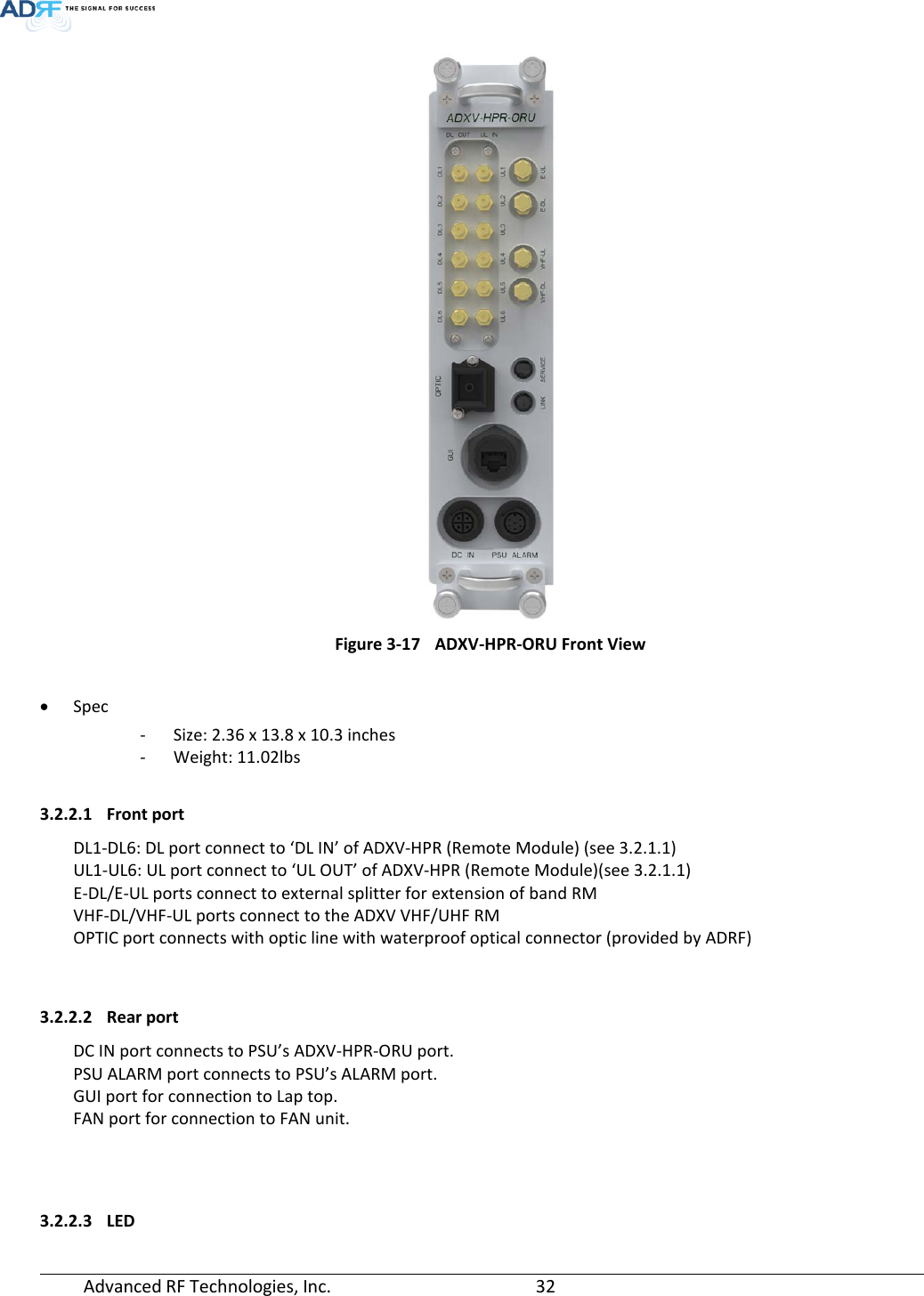
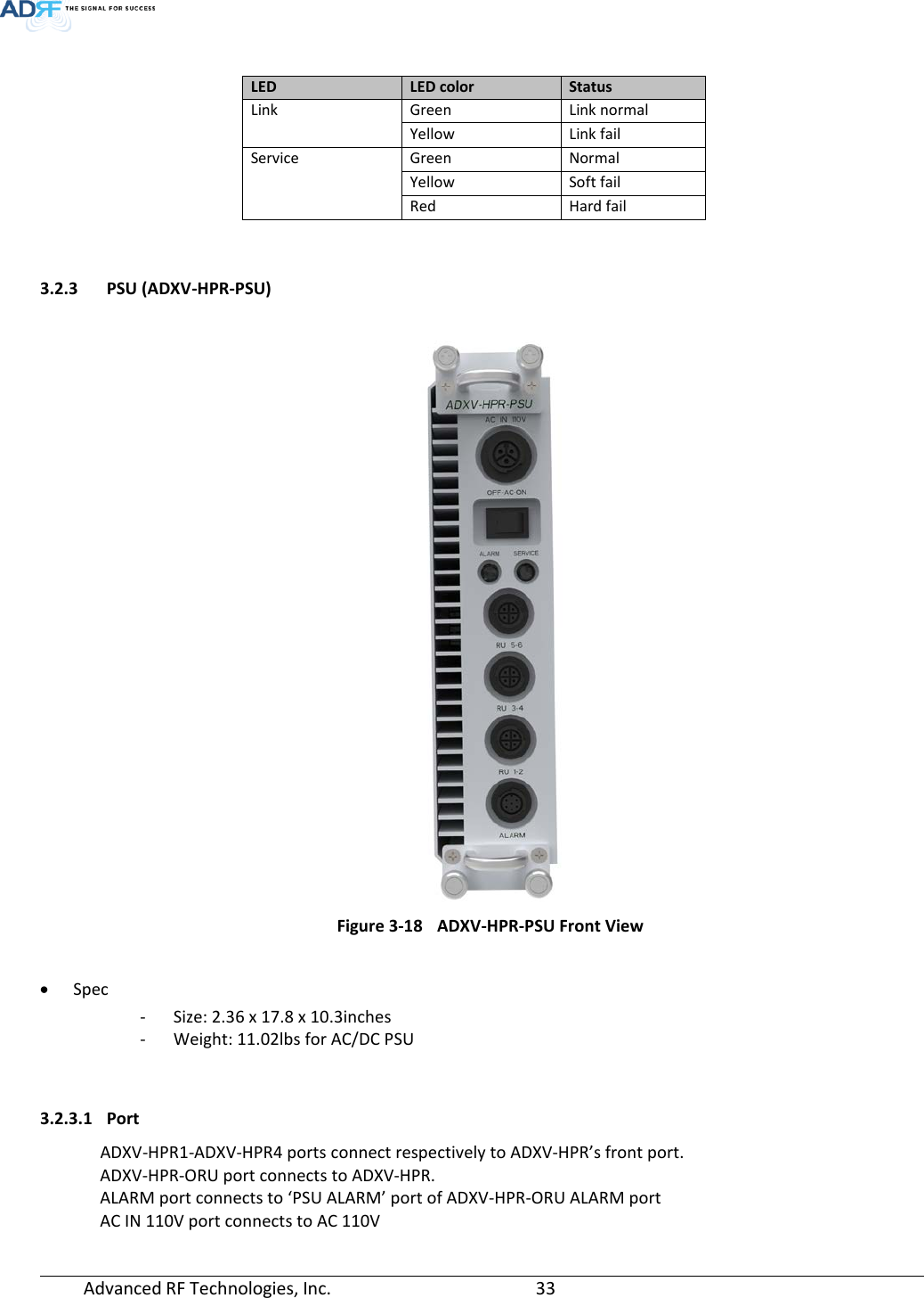
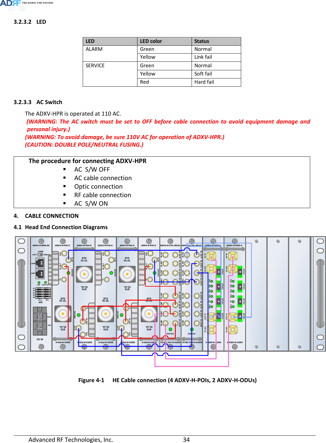
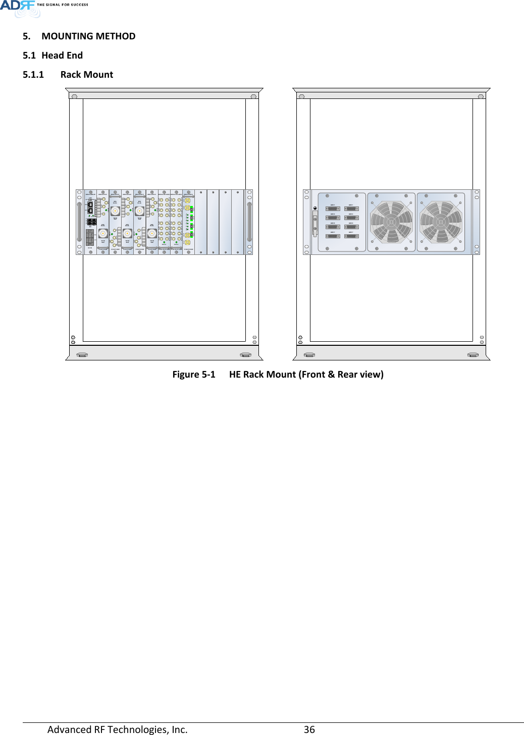
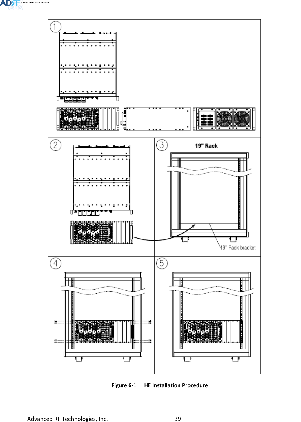
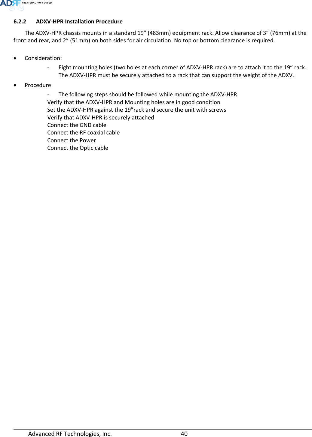
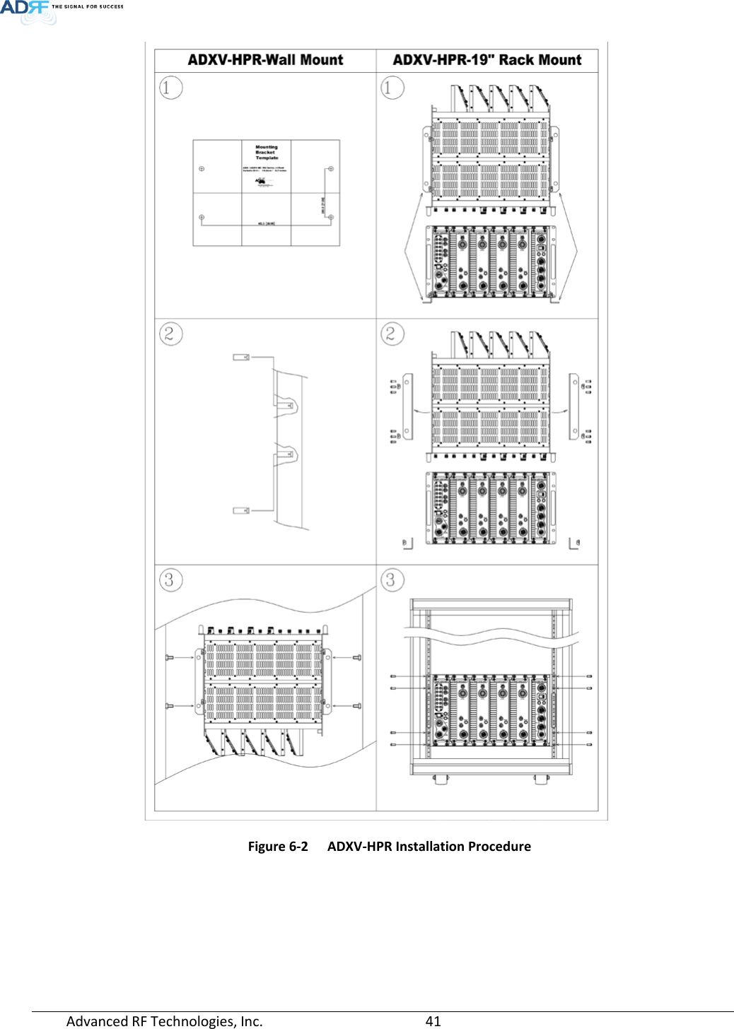
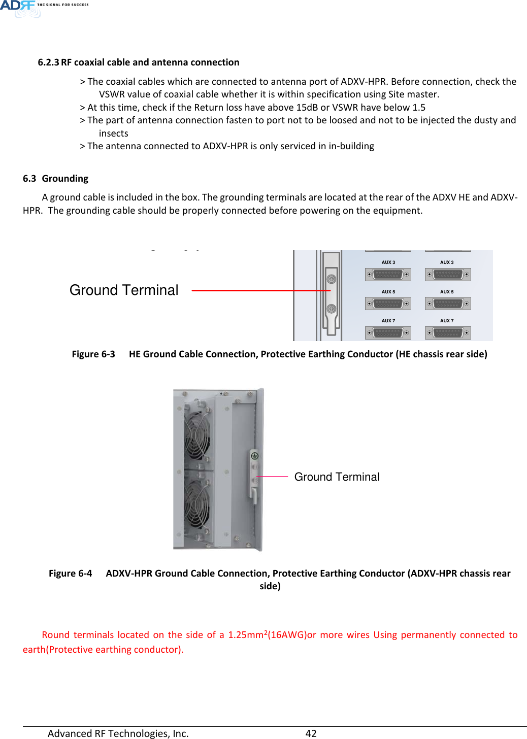
ADXV-HPR_User Manual_V0.3
Navigation menu
Upload a User Manual
Namespaces
Wiki Guide
HTML
PDF
Info
Views
User Manual
Discussion / Help
Navigation