ADRF KOREA ADXV-HPR DAS (Distributed Antenna System) User Manual ADXV DAS
ADRF KOREA, Inc. DAS (Distributed Antenna System) ADXV DAS
ADXV-HPR_User Manual_V0.3

Advanced RF Technologies, Inc.
ii
Information in this document is subject to change without notice.
Advanced RF Technologies, Inc. 1996-2015.
All rights reserved.
• Please send comments to:
E-Mail: info@adrftech.com
Phone: (818) 840-8131
(800) 313-9345
Fax: (818) 840-8138
• Address:
Advanced RF Technologies, Inc.
Attention: Technical Publications Department
3116 Vanowen St.
Burbank, CA 91505
USA
www.adrftech.com
Advanced RF Technologies, Inc.
iii
Revision History
Change List
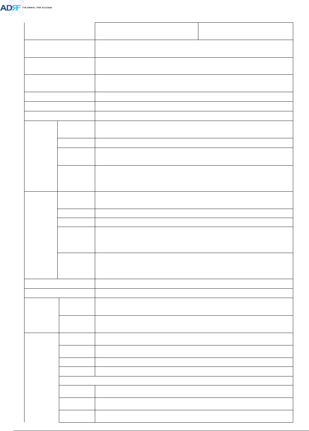
Version Change list Contents
Version Author Descriptions Date
0.1
CK Jo
Initial Release
05/08/2017
0.2
CK Jo
Update
07/07/2017
0.3
CK Jo
Update
07/27/2017

Advanced RF Technologies, Inc.
iv
Table of Contents
1. Introduction ...................................................................................................................................................... 11
1.1 Highlights ................................................................................................................................................... 11
1.2 ADXV-DAS/ADXV-HPR Quick View ............................................................................................................. 12
1.2.1 HE Quick View .................................................................................................................................... 12
1.2.2 ADXV-HPR Quick View ........................................................................................................................ 13
1.3 Warnings and Hazards ............................................................................................................................... 14
2. Block Diagram ................................................................................................................................................... 19
2.1 ADXV Block Diagram .................................................................................................................................. 19
2.2 ADXV Scalability ......................................................................................................................................... 20
3. ADXv Overview ................................................................................................................................................. 21
3.1 Head End .................................................................................................................................................... 21
3.1.1 NMS (Network Management System) ................................................................................................ 21
3.1.1.1 LEDs .......................................................................................................................................... 22
3.1.1.2 AAI ............................................................................................................................................ 22
3.1.1.3 Ethernet Port ............................................................................................................................ 23
3.1.1.4 Host/Remote Switch ................................................................................................................. 23
3.1.1.5 Power Connection (for DC -48V)............................................................................................... 24
3.1.1.6 Power Connection (for AC 110V) .............................................................................................. 24
3.1.2 POI (ADXV-H-POI-x) ............................................................................................................................ 25
3.1.2.1 LED ............................................................................................................................................ 25
3.1.2.2 RF Ports ..................................................................................................................................... 26
3.1.3 Channel Combiner (CHC, ADXV-H-CHC) ............................................................................................. 26
3.1.3.1 RF ports ..................................................................................................................................... 27
3.1.4 Optical Donor Unit (ODU, ADXV-H-ODU-4) ........................................................................................ 27
3.1.4.1 LEDs .......................................................................................................................................... 27
3.1.4.2 RF Ports ..................................................................................................................................... 28
3.1.4.3 Optic Ports ................................................................................................................................ 28
3.2 Remote Unit (ADXV-HPR) .......................................................................................................................... 29
3.2.1 Remote Module (ADXV-HPR-4XX) ...................................................................................................... 30
3.2.1.1 HPR ID numbering and RF line connection scheme .................................................................. 30
3.2.1.2 RF port ...................................................................................................................................... 31
3.2.1.3 Power port ................................................................................................................................ 31
3.2.1.4 LED ............................................................................................................................................ 31
3.2.2 Optical Remote Unit (ADXV-HPR-ORU) .............................................................................................. 31
3.2.2.1 Front port.................................................................................................................................. 32
3.2.2.2 Rear port ................................................................................................................................... 32
3.2.2.3 LED ............................................................................................................................................ 32

Advanced RF Technologies, Inc.
v
3.2.3 PSU (ADXV-HPR-PSU).......................................................................................................................... 33
3.2.3.1 Port ........................................................................................................................................... 33
3.2.3.2 LED ............................................................................................................................................ 34
3.2.3.3 AC Switch .................................................................................................................................. 34
4. Cable Connection .............................................................................................................................................. 34
4.1 Head End Connection Diagrams ................................................................................................................ 34
4.2 Remote Unit Connection Diagrams ........................................................................................................... 35
5. Mounting method ............................................................................................................................................. 36
5.1 Head End .................................................................................................................................................... 36
5.1.1 Rack Mount ........................................................................................................................................ 36
5.2 ADXV-HPR .................................................................................................................................................. 37
5.2.1 Rack Mount ........................................................................................................................................ 37
6. Installation ........................................................................................................................................................ 37
6.1 Pre-Installation Inspection ......................................................................................................................... 37
6.2 ADXV Installation Procedure...................................................................................................................... 38
6.2.1 HE Installation Procedure ................................................................................................................... 38
6.2.1.1 Installing a ADXV- HE in a rack .................................................................................................. 38
6.2.2 ADXV-HPR Installation Procedure ...................................................................................................... 40
6.2.3 RF coaxial cable and antenna connection .......................................................................................... 42
6.3 Grounding .................................................................................................................................................. 42
6.4 Optic Port Cleaning .................................................................................................................................... 43
7. Web-GUI ........................................................................................................................................................... 44
7.1 Web-GUI Setup .......................................................................................................................................... 44
7.1.1 DAS system/PC Connection Using Web-GUI ...................................................................................... 44
7.2 Administrator/User Mode ......................................................................................................................... 45
7.2.1 Common ............................................................................................................................................. 45
7.2.1.1 Navigation Tree......................................................................................................................... 45
7.2.1.2 Power Status ............................................................................................................................. 45
7.2.1.3 Commissioning Status ............................................................................................................... 45
7.2.1.4 Information ............................................................................................................................... 45
7.2.2 Status Tab ........................................................................................................................................... 47
7.2.2.1 Status – NMS ............................................................................................................................ 47
7.2.3 System ................................................................................................................................................ 50
7.2.3.1 System: Account ....................................................................................................................... 50
7.2.3.2 System: Logs ............................................................................................................................. 52
7.2.3.3 System: Update......................................................................................................................... 53
7.2.4 Help .................................................................................................................................................... 53
7.2.5 Logout ................................................................................................................................................. 54
7.3 Guest Mode ............................................................................................................................................... 54

Advanced RF Technologies, Inc.
vi
8. ADXV-System-Wide Specification ..................................................................................................................... 55
9. Mechanical Drawing ......................................................................................................................................... 59
9.1 HE ............................................................................................................................................................... 59
9.2 ADXV-HPR .................................................................................................................................................. 60

Advanced RF Technologies, Inc.
vii
Figures
Figure 1-1 ADXV-HPR HE Quick View (Front and Rear) ....................................................................................... 12
Figure 1-2 ADXV-HPR ADXV-HPR Quick View (Front and Rear) ........................................................................... 13
Figure 2-1 ADXV-HPR Block Diagram ................................................................................................................... 19
Figure 3-1 Head End Front View .......................................................................................................................... 21
Figure 3-2 ADXV-H-NMS Front View .................................................................................................................... 22
Figure 3-3 NMS LED ............................................................................................................................................. 22
Figure 3-4 NMS AAI .............................................................................................................................................. 23
Figure 3-5 Ethernet Port ...................................................................................................................................... 23
Figure 3-6 Host/Remote Switch ........................................................................................................................... 24
Figure 3-7 POI front View .................................................................................................................................... 25
Figure 3-8 POI LED ............................................................................................................................................... 25
Figure 3-9 ADXV-H-CHC Front View ..................................................................................................................... 26
Figure 3-10 ADXV-H-ODU-4 Front view ................................................................................................................ 27
Figure 3-11 ADXV-H-ODU-4 LED ............................................................................................................................ 28
Figure 3-12 ODU RF Ports ...................................................................................................................................... 28
Figure 3-13 ODU Optic Ports.................................................................................................................................. 28
Figure 3-14 ADXV-R Front and Rear (without FAN and with FAN) View ................................................................ 29
Figure 3-15 ADXV-R-4XX (RM) Front and Rear View .............................................................................................. 30
Figure 3-16 RM ID numbering and RF connection between OADXV-HPR and RM ................................................ 31
Figure 3-17 ADXV-R-OADXV-HPR Front View ........................................................................................................ 32
Figure 3-18 ADXV-R-PSU Front View ..................................................................................................................... 33
Figure 4-1 HE Cable connection (4 ADXV-H-POIs, 2 ADXV-H-ODUs) ................................................................... 34
Figure 4-2 ADXV-HPR 4ands connection .............................................................................................................. 35
Figure 5-1 HE Rack Mount (Front & Rear view) ................................................................................................... 36
Figure 5-2 ADXV-HPR Rack Mount Front and Rear View ..................................................................................... 37
Figure 6-1 HE Installation Procedure ................................................................................................................... 39
Figure 6-2 ADXV-HPR Installation Procedure....................................................................................................... 41
Figure 6-3 HE Ground Cable Connection, Protective Earthing Conductor (HE chassis rear side) ........................ 42
Figure 6-4 ADXV-HPR Ground Cable Connection, Protective Earthing Conductor (ADXV-HPR chassis rear side)
42
Figure 6-5 Optic Connector Cleaning (left) and Optic Port Cleaning (right) ........................................................ 43
Figure 6-6 SC/APC Optic Connector Dust Cap ..................................................................................................... 43
Figure 7-1 Login screen ........................................................................................................................................ 44
Figure 7-2 ADXV-HPR General Information ......................................................................................................... 46
Figure 7-3 SNMP (Install – NMS) .......................................................................................................................... 47
Figure 7-4 Location Setting (Install – NMS) ......................................................................................................... 48
Figure 7-5 External Modem Box Setting (Install – NMS) ..................................................................................... 48
Figure 7-6 Description (Install – NMS) ................................................................................................................. 48
Figure 7-7 SNMP Agent False Alarm Test (Install – NMS) .................................................................................... 49
Figure 7-8 Location Info / Installer Info (Install – NMS) ....................................................................................... 49
Figure 7-9 Date & Time Setting (Install – NMS) ................................................................................................... 50
Figure 7-10 Description (Install-Remote Module) ................................................................................................. 50
Figure 7-11 Account Management ........................................................................................................................ 50
Figure 7-12 New Account ...................................................................................................................................... 51
Figure 7-13 Change Password ................................................................................................................................ 52
Figure 7-14 User Log .............................................................................................................................................. 52
Figure 7-15 System update .................................................................................................................................... 53
Figure 7-16 Message after System update is complete ......................................................................................... 53
Figure 7-17 Help..................................................................................................................................................... 54
Figure 9-1 HE Drawing ......................................................................................................................................... 59


Advanced RF Technologies, Inc.
ix
Tables
Table 2-1 ADXV-HPR Scalability .......................................................................................................................... 20
Table 3-1 NMS LED Specifications ...................................................................................................................... 22
Table 3-2 NMS AAI Specifications ....................................................................................................................... 23
Table 3-3 POI LED Specifications ........................................................................................................................ 25
Table 3-4 POI RF port .......................................................................................................................................... 26
Table 3-5 ODU LED Specifications ...................................................................................................................... 28
Table 7-1 Account Information for Login ........................................................................................................... 44
Table 7-2 Navigation tree ................................................................................................................................... 45
Table 7-3 Power Supply Status ........................................................................................................................... 45
Table 7-4 Commissioning ICON .......................................................................................................................... 45
Table 7-5 System Summary Description ............................................................................................................. 47
Terms and Abbreviations
The following is a list of abbreviations and terms used throughout this document.
Abbreviation/Term Definition
AGC Automatic Gain Control
ALC Automatic Level Control
AROMS ADRF’ Repeater Operation and Management System
BCU Band Combiner Unit
BTS Base Transceiver Station
CDMA Code Division Multiple Access
CHC Channel combiner
CW Continuous Wave (un-modulated signal)
DAS Distributed Antenna System
DL Downlink
Downlink The path covered from the Base Transceiver Station (BTS) to the subscribers’ service area
via the repeater
HE Head End
HPA High Power Amplifier
HW Hardware
IF Intermediate Frequency
LNA Low Noise Amplifier
LTE Long Term Evolution
MS Mobile Station
NMS Network Management System
ODU Optical Donor Unit which is located in ADXV-HE.
OEU Optic Expansion Unit
PLL Phased Locked Loop
POI Point Of Interface
PSU Power Supply Unit
RF Radio Frequency
ADXV-HPR Remote Unit
RM Remote Module
SW Software

Advanced RF Technologies, Inc.
10
UL Uplink
Uplink The path covered from the subscribers’ service area to the Base Transceiver Station (BTS)
via the repeater
VSWR Voltage Standing Wave Ratio

Advanced RF Technologies, Inc.
11
1. INTRODUCTION
Currently the ADXV-HPR supports 700 MHz (Lower A, Lower B, Lower C, and Upper C), SMR800/Cellular, PCS,
AWS, WCS, BRS TD-LTE bands.
ADXV-HPR-437F, ADXV-HPR-43S8C, ADXV-HPR-46P, ADXV-HPR-46A, ADXV-HPR-45W, ADXV-HPR-46BT
1.1 Highlights
• Modular Structure (HE)
- Supports multi bands service in one body
- Supports up to 12 slot available for POI, ODU, CHC card, etc.
• Supports up to a of maximum of 96 Remote Units(using Optical Expansion Unit)
• 43/45/46dBm of downlink composite output power
• Requires only single strand of fiber per remote unit
• Operates with up to 5dBo optical loss
• Supports SNMP v1, v2, v3 (get, set & traps)
• Web-based GUI Interface; No 3rd party GUI software required
• Web-GUI connectivity via DHCP in host mode
• Versatility and Usability: ADXV-DAS gives total control to the user. Control parameters such as gain, output
power, and alarm threshold can be changed using Web-GUI interface allowing the user to fine tune the system
to the given RF environment.
Advanced RF Technologies, Inc.
12
1.2 ADXV-DAS/ADXV-HPR Quick View
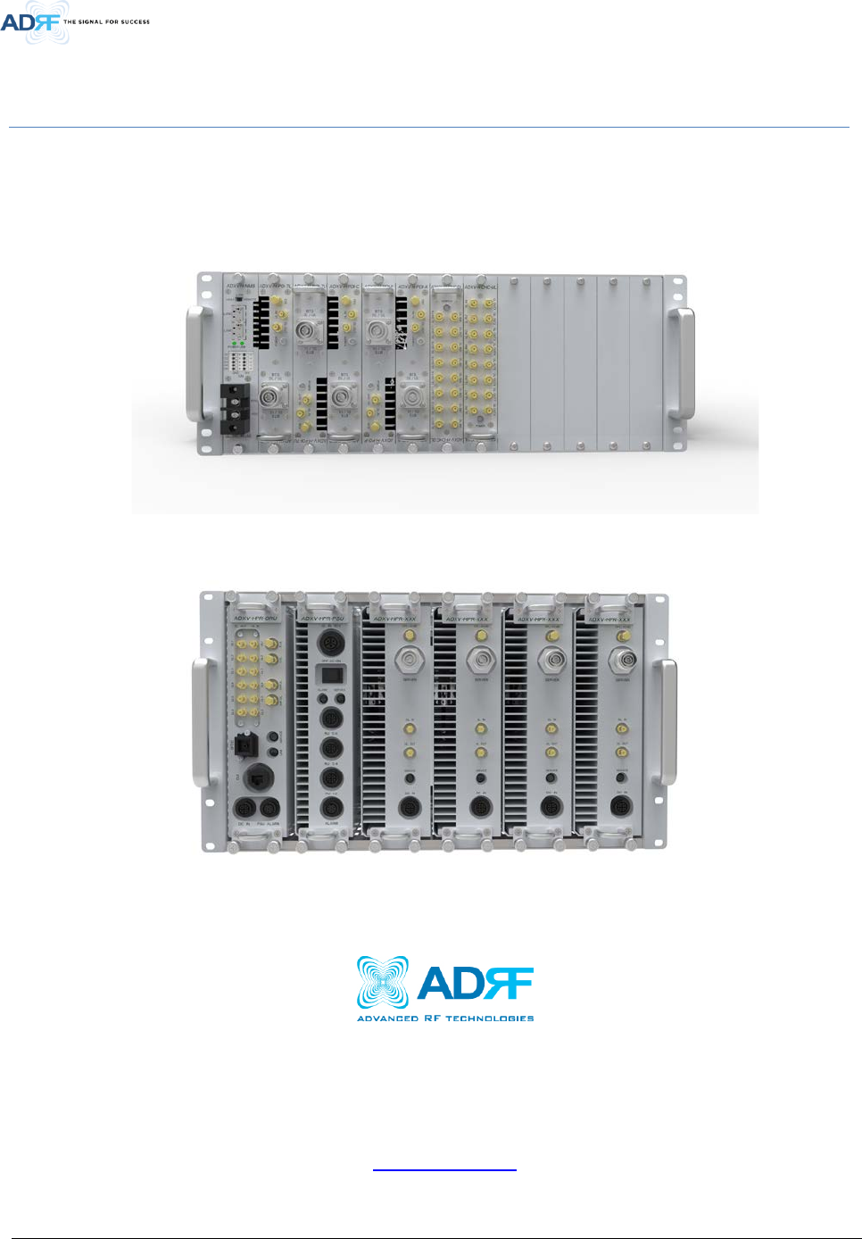
1.2.1 HE Quick View
Figure 1-1 ADXV-DAS HE Quick View (Front and Rear)
AUX 1
AUX 3
AUX 5
AUX 7
AUX 1
AUX 3
AUX 5
AUX 7
AUX Port
Fan Unit
Ground Terminal
AAI
SERVICE
HOST
ADXV-H-NMS-DC
LAN1
LAN0
LAN0
RTN
-48V
DC IN
REMOTE
01
02
03
04
05
P(+)
LINK
N(-)
UL IN
DL OUT
SERVICE
E911
DL/UL
ADXV-H-POI-X
ADXV-H-POI-X
UL
DL/UL
BTS
BTS
UL IN
DL OUT
SERVICE
E911
DL/UL
ADXV-H-POI-X
ADXV-H-POI-X
UL
DL/UL
BTS
BTS
UL IN
DL OUT
SERVICE
E911
DL/UL
ADXV-H-POI-X
ADXV-H-POI-X
UL
DL/UL
BTS
BTS
UL IN
DL OUT
SERVICE
E911
DL/UL
ADXV-H-POI-X
ADXV-H-POI-X
UL
DL/UL
BTS
BTS
UL IN
DL OUT
SERVICE
E911
DL/UL
ADXV-H-POI-X
ADXV-H-POI-X
UL
DL/UL
BTS
BTS
DL IN 1
SERVICE
ADXV-H-CHC-88-DL
DL IN7 DL IN6 DL IN5 DL IN4 DL IN3 DL IN2 DL IN1DL IN8
DL OUT7DL OUT6
DL OUT5DL OUT4DL OUT3
DL OUT2DL OUT1 DL OUT8
ADXV-H-CHC-88-DL
DL IN 1
SERVICE
ADXV-H-CHC-88-UL
DL IN7 DL IN6 DL IN5 DL IN4 DL IN3 DL IN2 DL IN1
DL IN8
DL OUT7DL OUT6DL OUT5DL OUT4
DL OUT3DL OUT2DL OUT1 DL OUT8
ADXV-H-CHC-88-UL
VHF UL
ADXV-H-ODU-4
ADXV-H-ODU-4
UL OUT
DL IN VHF UL
PWRLD
PD4PD3
PD2PD1
VHF DL
OPTIC1 OPTIC2 OPTIC3 OPTIC4
Network Management System
(NMS)
Point Of Interface (POI)
DL Channel Combiner
(CHC)
Optical Donor Unit (ODU)
UL Channel Combiner
(CHC)
Advanced RF Technologies, Inc.
13
1.2.2 ADXV-HPR Quick View
Optical Remote Unit
(ORU)
High Power Remote Module
(HPR)
Power Supply Unit
(PSU)
High Power Remote Module
(HPR)
Power Supply Unit
(PSU)
Optical Remote Unit
(ORU)
Ground Terminal
Figure 1-2 ADXV-HPR Quick View (Front and Rear)
Advanced RF Technologies, Inc.
14
1.3 Warnings and Hazards
Opening the ADXV-HPR could result in electric shock and may cause
severe injury.
WARNING!
ELECTRIC
SHOCK
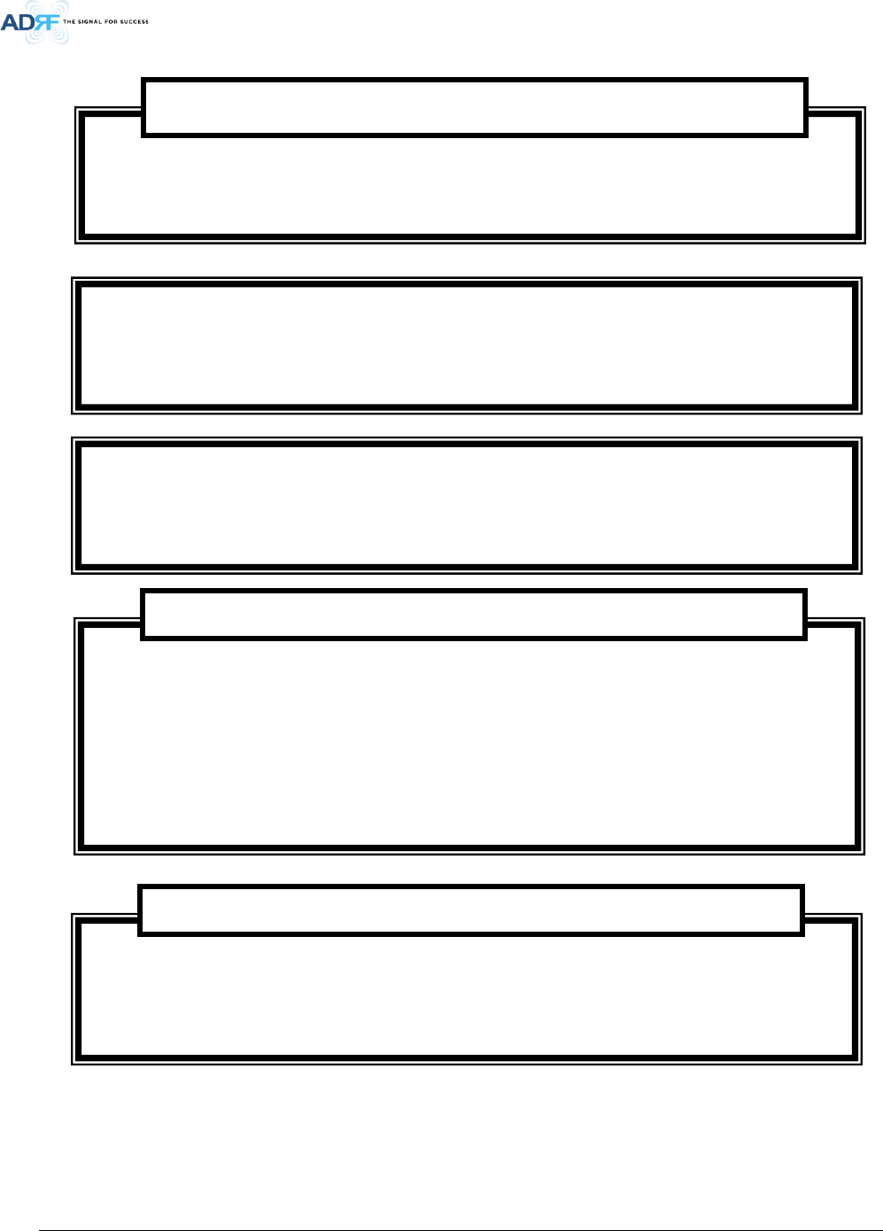
Working with the ADXV-HPR while in operation, may expose the technician to RF
electromagnetic fields that exceed FCC rules for human exposure. Visit the FCC website at
www.fcc.gov/oet/rfsafety to learn more about the effects of exposure to RF electromagnetic
fields.
WARNING! EXPOSURE TO RF
Actual separation distance is determined upon gain of antenna used.
Please maintain a minimum safe distance of at least 600 cm while operating near the donor and the server antennas.
RF EXPOSURE & ANTENNA PLACEMENT Guidelines
- Part 27.50
Antennas must be installed in accordance with FCC 27.50 and SRSP 518. With 17dBi gain antennas the height of the
antenna above average terrain (HAAT) must not exceed 1164m. For different gain antennas refer to the relevant
Rules.
- Part 90.635 requirement
Antennas must be installed in accordance with FCC 90.635. With 17 dBi gain antennas the height of the antenna
above average terrain (HAAT) is permitted over 443m. For different gain antennas refer to the relevant rules.
ANTENNA INSTALLATION Guidance
Advanced RF Technologies, Inc.
15
Opening or tampering the ADXV-HPR will void all warranties.
WARRANTY
Lithium Battery: CAUTION. RISK OF EXPLOSION IF BATTERY IS REPLACED BY INCORRECT TYPE.
DISPOSE OF USED BATTERIES ACCORDING TO INSTADXV-HPRCTIONS.
Ethernet Instructions: This equipment is for indoor use only. All cabling should be limited to inside
the building.
NOTE: This equipment has been tested and found to comply with the limits for a Class A digital
device, pursuant to part 15 of the FCC rules. These limits are designed to provide reasonable
protection against harmful interference when the equipment is operated in a commercial
environment. This equipment generates, uses, and can radiate radio frequency energy and, if not
installed and used in accordance with the instruction manual, may cause harmful interference to
radio communications. Operation of this equipment in a residential area is likely to cause harmful
interference in which case the user will be required to correct the interference at their own
expense.
FCC Part 15 Class A
WARNING. THIS is NOT a CONSUMER device. It is designed for installation by FCC LICENSEES and
QUALIFIED INSTALLERS. You MUST have an FCC LICENSE or express consent of an FCC Licensee to
operate this device. Unauthorized use may result in significant forfeiture penalties, including
penalties in excess of $100,000 for each continuing violation.
FCC Part 20
Advanced RF Technologies, Inc.
16
Fiber optic ports of the ADXV-HPR emit invisible laser radiation at the 1310, 1550nm wavelength
window.
To avoid eye injury never look directly into the optical ports, patch cords or optical cables. Do not
stare into beam or view directly with optical instruments. Always assume optical output is on.
Only technicians familiar with fiber optic safety practices and procedures should perform optical
fiber connections and disconnections of the ADXV-HPR and the associated cables.
The ADXV-HPR complies with 21 CFR 1040.10 and 1040.11 except for deviations pursuant to laser
notice No.50 (July26. 2001)@IEC 60825-1, Amendment2 (Jan. 2001).
Laser Safety
Do not remove the protective covers on the fiber optic connectors until a connection is ready to be
made. Do not leave connectors uncovered when not connected.
The tip of the fiber optic connectors should not come into contact with any object or dust.
Refer to the cleaning procedure for information on the cleaning of the fiber tip.
Care of Fiber Optic Connectors
Use of unauthorized antennas, cables, and/or coupling devices not conforming with
ERP/EIRP and/or indoor-only restrictions is prohibited.
Home/ personal use are prohibited
Only 50 ohm rated antennas, cables and passive equipment shall be used with this remote. Any
equipment attached to this device not meeting this standard may cause degradation and
unwanted signals in the bi-directional system. All components connected to this device must
operate in the frequency range of this device.
Only 50 ohm rated antennas, cables and passive components operating from 150 - 3 GHz shall
be used with this device.
Advanced RF Technologies, Inc.
17
RSS-GEN, Sec. 7.1.2 – (transmitters)
Under Industry Canada regulations, this radio transmitter may only operate using an antenna of a type and
maximum (or lesser) gain approved for the transmitter by Industry Canada. To reduce potential radio
interference to other users, the antenna type and its gain should be so chosen that the equivalent
isotropically radiated power (e.i.r.p.) is not more than that necessary for successful communication.
Conformément à la réglementation d’Industrie Canada, le présent émetteur radio peut fonctionneravec
une antenne d’un type et d’un gain maximal (ou inférieur) approuvé pour l’émetteur par Industrie Canada.
Dans le but de réduire les risques de brouillage radioélectrique à l’intention desautres utilisateurs,
il faut choisir le type d’antenne et son gain de sorte que la puissance isotroperayonnée quivalente (p.i.r.e.)
ne dépassepas l’intensité nécessaire à l’établissement d’une communication satisfaisante.
RSS-GEN, Sec. 7.1.2 – (detachable antennas)
This radio transmitter (identify the device by certification number, or model number if Category II)has been
approved by Industry Canada to operate with the antenna types listed below with the maximum permissible
gain and required antenna impedance for each antenna type indicated. Antenna types not included in this list,
having a gain greater than the maximum gain indicated for that type, are strictly prohibited for use with this
device.
Le présent émetteur radio (identifier le dispositif par son numéro de certification ou son numéro de
modèle s’il fait partie du matériel de catégorie I) a été approuvé par Industrie Canada pour fonctionner
avec les types d’antenne énumérés ci-dessous et ayant un gain admissible maximal et l’impédance requise
pour chaque type d’antenne. Les types d’antenne non inclus dans cette liste,ou dont le gain est supérieur
au gain maximal indiqué, sont strictement interdits pour l’exploitation de l’émetteur.
Double Pole/Neutral Fusing.
CAUTION
for PERMANENTLY CONNECTED EQUIPMENT, a readily accessible disconnect device shall be
incorporated external to the equipment;
Permanent earthing
WARNING: This is NOT a CONSUMER device. It is designed for installation by an installer approved
by an ISED licensee. You MUST have an ISED LICENCE or the express consent of an ISED licensee to
operate this device.

Advanced RF Technologies, Inc.
18
RF Radiation Exposure
This equipment complies with RF radiation exposure limits set forth for an uncontrolled environment.
This equipment should be installed and operated with a minimum distance of 600 cm between the radiator
and your body. This transmitter must not be co-located or operating in conjunction with any other antenna or
transmitter. RF exposure will be addressed at time of installation and the use of higher gain antennas
require larger separation distances.
RSS-102 RF Exposure
L’antenne (ou les antennes) doit être installée de façon à maintenir à tout instant une distance
minimum de au moins 600 cm entre la source de radiation (l’antenne) et toute personne physique.
Cet appareil ne doit pas être installé ou utilisé en conjonction avec une autre antenne ou émetteur.
Advanced RF Technologies, Inc.
19
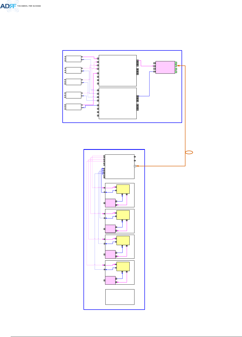
2. BLOCK DIAGRAM
2.1 ADXV Block Diagram
Figure 2-1 ADXV Block Diagram
AWS
POI
TX
Common
RX
DL
UL
700L
POI
TX
Common
RX
DL
UL
ODU#1
DL IN
V/UHF(136~512)
DL IN
(698~2690)
UL OUT
V/UHF(136~512)
UL OUT
(698~2690)
PCS
POI
TX
Common
RX
DL
UL
S8C
POI
TX
Common
RX
DL
UL
PSU
Duplexer
7F
RM
700U
POI
TX
Common
RX
DL
UL
ORU
RU
HE
CHC
RF
CHC
Duplexer
S8C
RM
RF
Duplexer
PCS
RM
RF
Duplexer
AWS
RM
RF
Advanced RF Technologies, Inc.
20
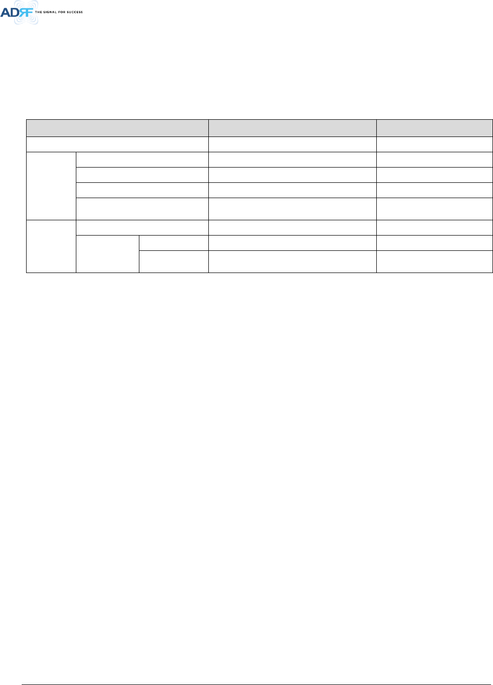
2.2 ADXV Scalability
Table 2-1 ADXV Scalability
Unit Scalability Remarks
Supported band 700F, S8C, AWS, PCS, WCS, BRS TD-LTE
HE
POI No limitation in 12 slots except NMS
NMS 1
CHC No limitation in 12 slots except NMS
Optic Unit
No limitation in 12 slots except NMS
In case of Aux, No limit in 8 Aux ports
ADXV-HPR
ADXV-HPR 64
PSU
(ADXV-HPR)
Adaptor type 1 per Remote Module(RM)
19” rack mount
(AC or DC)
1
Capable of supplying power
to 4 Remote Modules
Advanced RF Technologies, Inc.
21
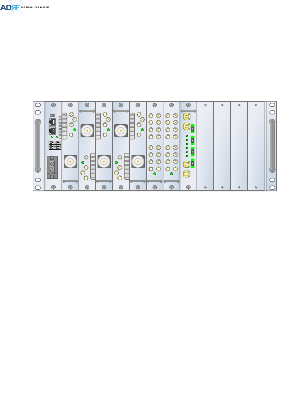
3. ADXV OVERVIEW
3.1 Head End
The head end unit must always be connected to the Base Station using a direct cabled connection. This
system has not been approved for use with a wireless connection via server antenna to the base station.
• Specifications
- Size: 19.0 x 19.7 x 7inches (482 x 500 x 178 mm)
- Weight: 64.8lbs @5 POI, 2 CHC, ODU and NMS
- Power Input: 110VAC(optional) or -48VDC
Figure 3-1 Head End Front View
3.1.1 NMS (Network Management System)
• Functions and features
- Supports SNMP v1, v2, and v3 (get, set & trap) and web-based GUI Interface.
- Monitors alarms and status
- Provides control interfaces with all subordinate modules
- Provides overall DAS structure via the auto tree update function
• Spec
- Size: 19.0 x 12.1 x 1.7inches
- Weight: 3.5lbs
AAI
SERVICE
HOST
ADXV-H-NMS-DC
LAN1
LAN0
LAN0
RTN
-48V
DC IN
REMOTE
01
02
03
04
05
P(+)
LINK
N(-)
UL IN
DL OUT
SERVICE
E911
DL/UL
ADXV-H-POI-X
ADXV-H-POI-X
UL
DL/UL
BTS
BTS
UL IN
DL OUT
SERVICE
E911
DL/UL
ADXV-H-POI-X
ADXV-H-POI-X
UL
DL/UL
BTS
BTS
UL IN
DL OUT
SERVICE
E911
DL/UL
ADXV-H-POI-X
ADXV-H-POI-X
UL
DL/UL
BTS
BTS
UL IN
DL OUT
SERVICE
E911
DL/UL
ADXV-H-POI-X
ADXV-H-POI-X
UL
DL/UL
BTS
BTS
UL IN
DL OUT
SERVICE
E911
DL/UL
ADXV-H-POI-X
ADXV-H-POI-X
UL
DL/UL
BTS
BTS
DL IN 1
SERVICE
ADXV-H-CHC-88-DL
DL IN7 DL IN6 DL IN5 DL IN4DL IN3DL IN2 DL IN1DL IN8
DL OUT7
DL OUT6
DL OUT5
DL OUT4DL OUT3DL OUT2
DL OUT1 DL OUT8
ADXV-H-CHC-88-DL
DL IN 1
SERVICE
ADXV-H-CHC-88-UL
DL IN7 DL IN6 DL IN5 DL IN4 DL IN3 DL IN2 DL IN1
DL IN8
DL OUT7DL OUT6DL OUT5
DL OUT4
DL OUT3
DL OUT2
DL OUT1 DL OUT8
ADXV-H-CHC-88-UL
VHF UL
ADXV-H-ODU-4
ADXV-H-ODU-4
UL OUT
DL IN VHF UL
PWRLD
PD4
PD3
PD2
PD1
VHF DL
OPTIC1 OPTIC2 OPTIC3OPTIC4
Advanced RF Technologies, Inc.
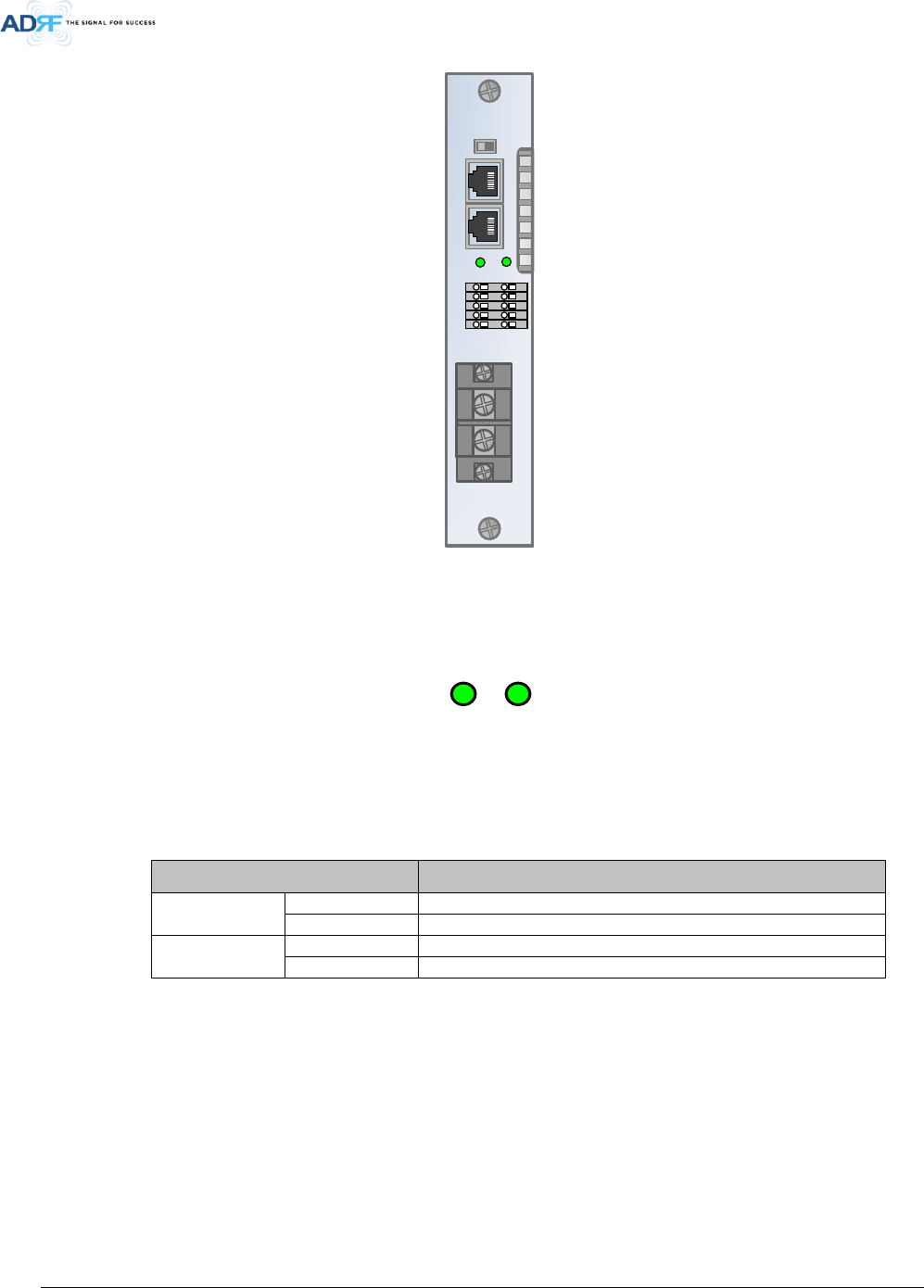
22
Figure 3-2 ADXV-H-NMS Front View
3.1.1.1 LEDs
NMS has LEDs on the front panel as shown in Figure 3-3.
Figure 3-3 NMS LED
Table 3-1 NMS LED Specifications
ADXV-HPR-NMS Specifications
POWER
Solid Green
NMS power is ON
OFF
NMS power is OFF
LINK
Solid Red
HE Link Fail alarm exists in the system
Solid Green
No HE Link Fail alarms are present in the system
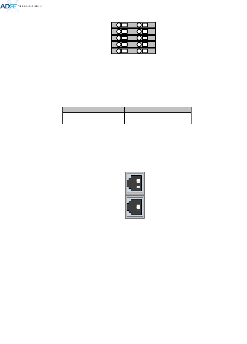
3.1.1.2 AAI
AAI
SERVICE
HOST
ADXV-H-NMS-DC
LAN1
LAN0
LAN0
RTN
-48V
DC IN
REMOTE
01
02
03
04
05
P(+)
LINK
N(-)
LINKPOWER
Advanced RF Technologies, Inc.
23
Figure 3-4 NMS AAI
NMS has 5 external alarms out interface pins on the front panel.
Table 3-2 NMS AAI Specifications
AAI Alarm Status
Output
Normal
High Impedance (Open)
Alarm
Low Impedance (Short)
3.1.1.3 Ethernet Port
The Ethernet port can be used to communicate directly with the ADXV-HPR using a RJ-45 crossover cable or can
also be used to connect the ADXV-HPR to an external modem box.
Figure 3-5 Ethernet Port
3.1.1.4 Host/Remote Switch
The Host/Remote Switch allows the user to switch the default Repeater IP, Subnet Mask, and Gateway of the
repeater to an alternative setup. These settings can be adjusted by logging into the ADXV-HPR in HOST mode and
configuring the settings under the Modem Box Setting section under the Install Page of NMS.
Once the settings are set, flipping the switch to the REMOTE position will reboot NMS module with the new
alternate settings. Please note that when the NMS is set to the REMOTE position, DHCP is disabled and the NMS will
not automatically assign an IP address to any device that connects directly to the NMS.
01
02
03
04
05
P(+) N(-)
LAN1
LAN0
Advanced RF Technologies, Inc.
24
Figure 3-6 Host/Remote Switch
• Host IP: 192.168.63.1 (Fixed IP, unable to modify this IP address)
• Remote IP: 192.168.63.5 (Default IP, but can be modified in Host mode)
3.1.1.5 Power Connection (for DC -48V)
NMS has terminal block for DC power connection on the front panel.
You should verify power polarity of each power line and should turn on the power after power connection
necessarily.
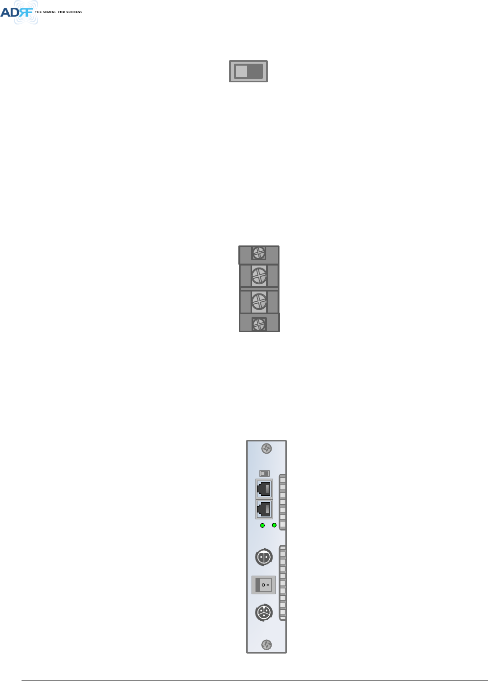
3.1.1.6 Power Connection (for AC 110V)
NMS has Chogori connectors for AC power feeding and battery backup on the front panel.
You should verify power polarity of each power line and should turn on the power after power connection
necessarily.
HOST
LAN0
REMOTE
RTN
-48V
DC IN
SERVICE
HOST
ADXV-H-NMS-AC
LAN1
LAN0
LAN0
AC IN 110V
REMOTE
LINK
OFF - AC - ON
BATTERY
Advanced RF Technologies, Inc.
25
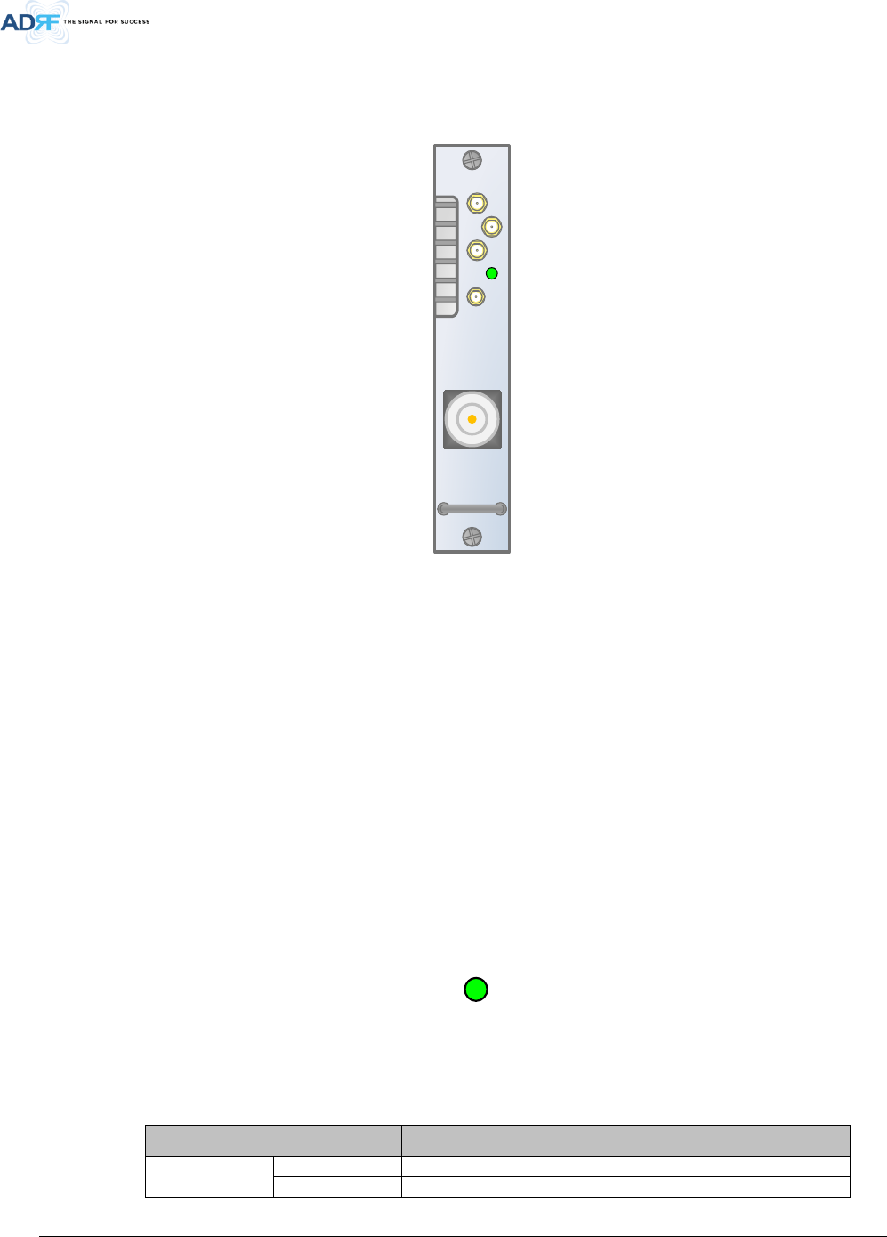
3.1.2 POI (ADXV-H-POI-x)
Figure 3-7 POI front View
• Functions and features
- Provide RF interface with BTS
- Each POI has independent gain control and filtering
- Modular type and hot swappable
- Supports duplex port and simplex RX port
- Easily support additional frequency bands by adding a single POI
- Reduces complexity and overall equipment size
• Specifications
- Size: 1.3 x 17.1 x 6.85inches
- Weight: 6.2lbs
3.1.2.1 LED
POI has LEDs on the front panel as shown in Figure 3-8.
Figure 3-8 POI LED
Table 3-3 POI LED Specifications
POI Specifications
Power
Solid Green
POI power is ON and POI is normal status
Solid Red
POI power is ON and POI is hard fail alarm status
UL IN
DL OUT
SERVICE
E911
DL/UL
ADXV-H-POI-X
ADXV-H-POI-X
UL
DL/UL
BTS
BTS
POWER
Advanced RF Technologies, Inc.
26
Solid Yellow
POI power is ON and POI is soft fail alarm status
3.1.2.2 RF Ports
BTS DL/UL, DL OUT, UL IN, E911 Ports (refer to Figure 3-7) are located at the front of the POI
Table 3-4 POI RF port
RF Port
Function
BTS DL/UL
BTS Interface, DL duplexer Input, UL duplexer output
DL OUT
DL output
UL IN
UL input
UL OUT
UL output not passing through duplexer
E911
E911 RF interface
3.1.3 Channel Combiner (CHC, ADXV-H-CHC)
Figure 3-9 ADXV-H-CHC Front View
• Functions & Features
- Combines DL signals received from each POI and feeds the combined signals to the ADXV-H-ODU
- Combines UL signals received from each ADXV-HPR and feeds the combined signal to the ADXV-H-
POI
- No limit of installation number and location to install POI, ODU, CHC card in 12 slots except NMS
card
• Specifications
- Size: 1.3 x 17.1 x 6.85inches
- Weight: 4.4lbs per CHC
DL IN 1
SERVICE
ADXV-H-CHC-88-DL
DL IN7 DL IN6 DL IN5 DL IN4 DL IN3 DL IN2 DL IN1DL IN8
DL OUT7DL OUT6DL OUT5DL OUT4DL OUT3DL OUT2DL OUT1 DL OUT8
ADXV-H-CHC-88-DL
DL IN 1
SERVICE
ADXV-H-CHC-88-UL
DL IN7 DL IN6 DL IN5 DL IN4 DL IN3 DL IN2 DL IN1DL IN8
DL OUT7DL OUT6DL OUT5DL OUT4DL OUT3DL OUT2DL OUT1 DL OUT8
ADXV-H-CHC-88-UL
Advanced RF Technologies, Inc.
27
3.1.3.1 RF ports
3.1.3.1.1 RF ports at the front panel (DL 1 to DL 8, UL 1 to UL 8)
DL 1(to DL 8) & UL 1(to UL 8) RF ports are connected to DL OUT/UL IN Ports at the front panel of POI.
• Receive the downlink signal from each POI
• Split the uplink signal received from ODU to each POI
3.1.3.1.2 RF ports at the back panel (DL 1 to DL 8, UL 1 to UL 8)
DL 1(to DL 8) & UL 1(to UL 8) RF ports are connected to DL IN/UL OUT Ports at the back panel of ODU.
• Transfer the combined downlink signals to ODU
• Receive the uplink signal from ODU
3.1.4 Optical Donor Unit (ODU, ADXV-H-ODU-4)
Figure 3-10 ADXV-H-ODU-4 Front view
• Functions & Features
- Converts signal from RF to optic and transports signals up to a maximum of 10Km (optical 5dBo
loss including optical connection loss).
- One ADXV-H-ODU-4 supports up to 4 ADXV-HPRs
- Minimizes the number of optic fiber cable need by transporting multi band signals over a single
strand of fiber using WDM technology.
• Spec
- Size: 1.3 x 17.1 x 6.85inches
- Weight: 5.3lbs
3.1.4.1 LEDs
The ADXV-H-ODU-4 has the following LEDs on the front panel as shown in Figure 3-11.
VHF UL
ADXV-H-ODU-4
ADXV-H-ODU-4
UL OUT
DL IN VHF UL
PWRLD
PD4
PD3PD2PD1
VHF DL
OPTIC1 OPTIC2 OPTIC3 OPTIC4
Advanced RF Technologies, Inc.
28
Figure 3-11 ADXV-H-ODU-4 LED
Table 3-5 ODU LED Specifications
ADXV-HPR-Module Specifications
PWR
Solid Green
Module power is ON
OFF
Module power is OFF
LD
OFF
ODU is not installed
Solid Yellow
LD Fail alarm exists in the ODU
Solid Green
No LD Fail alarm is present in the ODU
PD1 to PD4
Solid Yellow
PD Fail alarm exists
Solid Green
No PD Fail alarm is present
3.1.4.2 RF Ports
Figure 3-12 ODU RF Ports
3.1.4.2.1 DL IN/UL OUT
The combined downlink signal received from ADXV-H-CHC is transferred to the DL IN at the back of ODU.
The UL OUT port connects any of the ports on back of the ADXV-H-CHC labeled UL 1 ~8.
3.1.4.2.2 VHF DL/VHF UL
VHF DL/UHF UL ports are used to support Public Safety in the VHF & UHF frequency bands. VHF/UHF signals for
Public Safety bypass the ADXV-H-CHC and connect directly to the VHF DL/UHF UL ports of the ADXV-H-ODU.
3.1.4.3 Optic Ports
LINK 4 LINK 3 LINK 2 LINK 1
Figure 3-13 ODU Optic Ports
The ADXV-H-ODU4 has (4) optic ports and can support up to (4) Main ADXV-HPR’s. Likewise, the ADXV-H-ODU1
has (1) optic ports and can support up to (1) Main ADXV-HPR.
PWRLDPD4PD3PD2PD1
UL OUT
DL IN VHF ULVHF DL
Advanced RF Technologies, Inc.
29
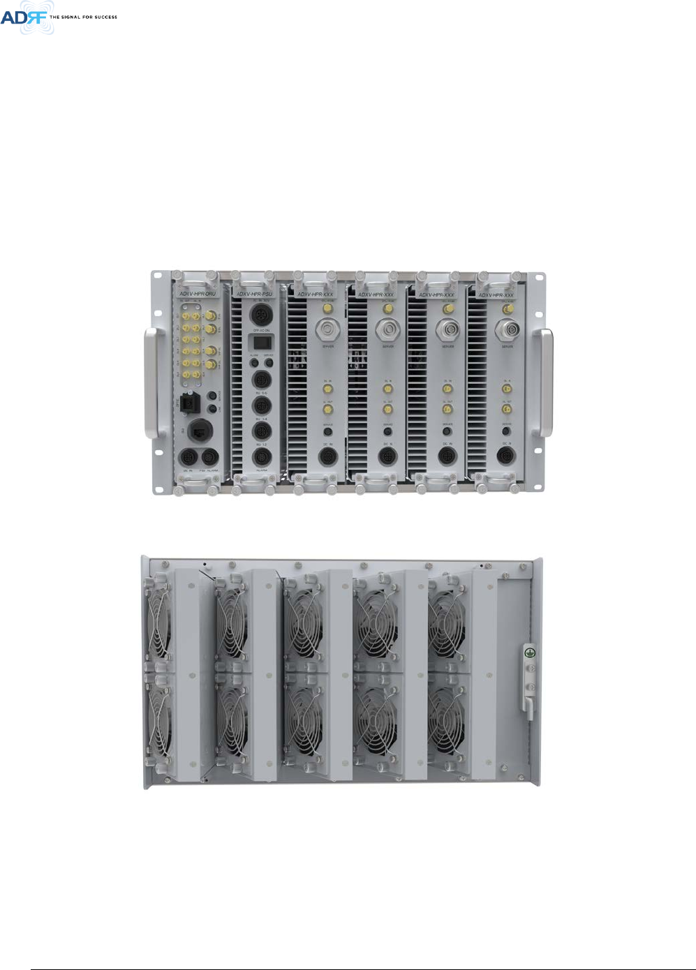
3.2 ADXV-HPR
- A remote unit (single ADXV-HPR chassis base) is composed of an ADXV-HPR-ORU (Optical Remote
Unit), a PSU (Power Supply Unit) and plural band’s RM (Remote Module).
• Specifications
- Size: 19.0 x 14.96 x 7 inches (482 x 380 x 178 mm)
- Weight: 62.17lbs (28.2 Kg)@4 HPR(437F/43S8C/46P/46A), ADXV-HPR-ORU and PSU
- Power Input: 110VAC or -48VDC
Figure 3-14 ADXV-R Front and Rear View
Advanced RF Technologies, Inc.
30
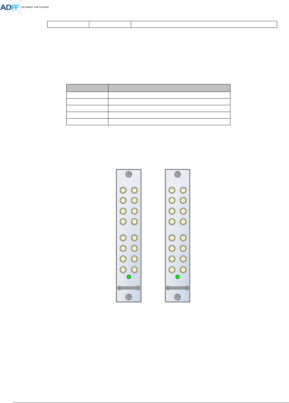
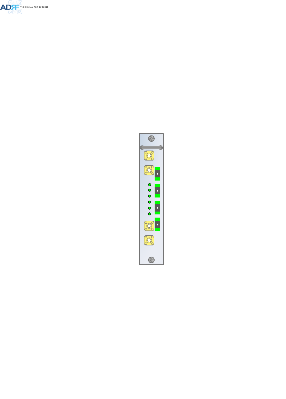
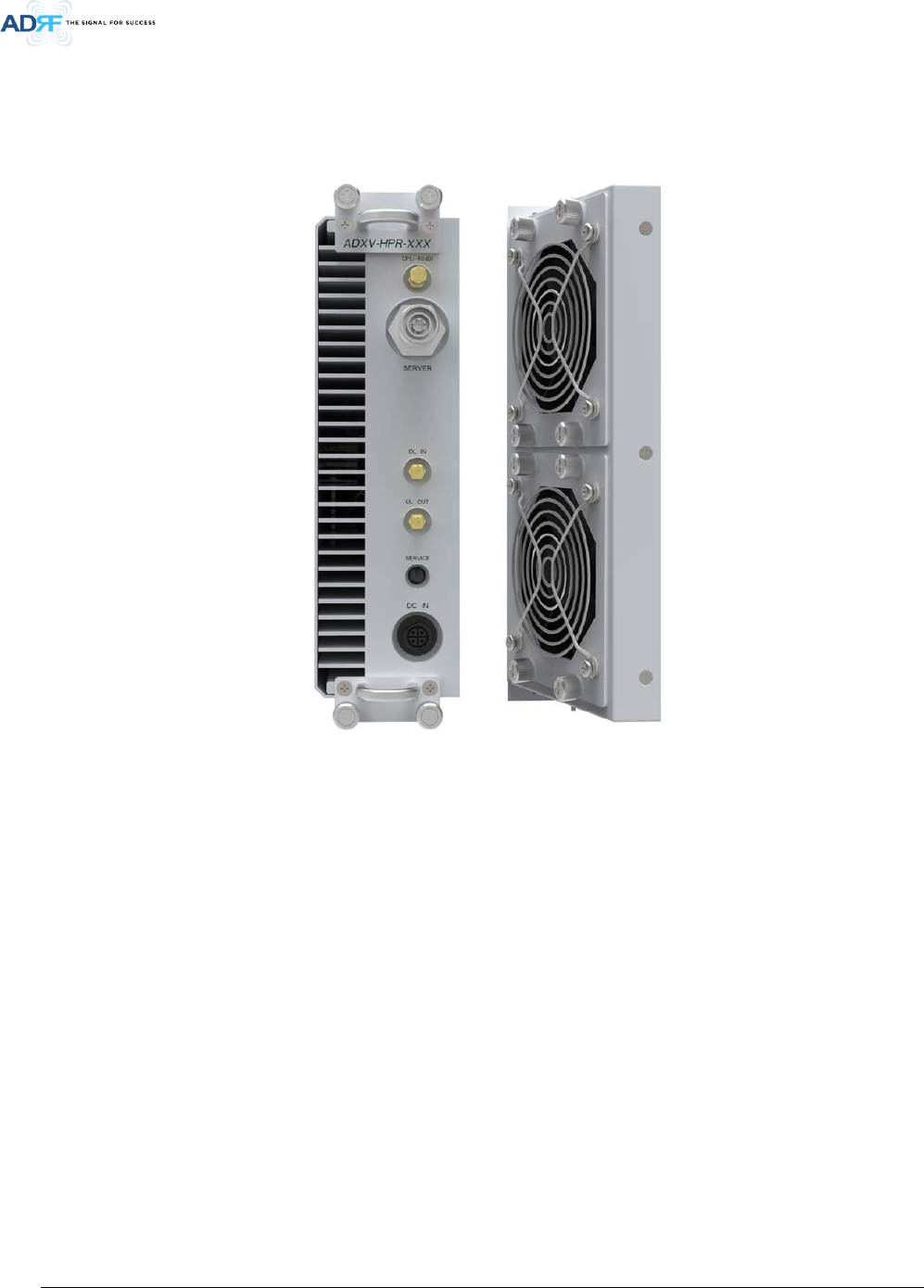
3.2.1 Remote Module (ADXV-HPR-4XX)
Figure 3-15 ADXV-HPR-4XX (RM) Front and Rear View
• Spec
- Size: 2.75 x 17.8 x 10.3 inches
- Weight: 13.22lbs for 437F, 43S8C, 46P, 46A, 45W, 46BT
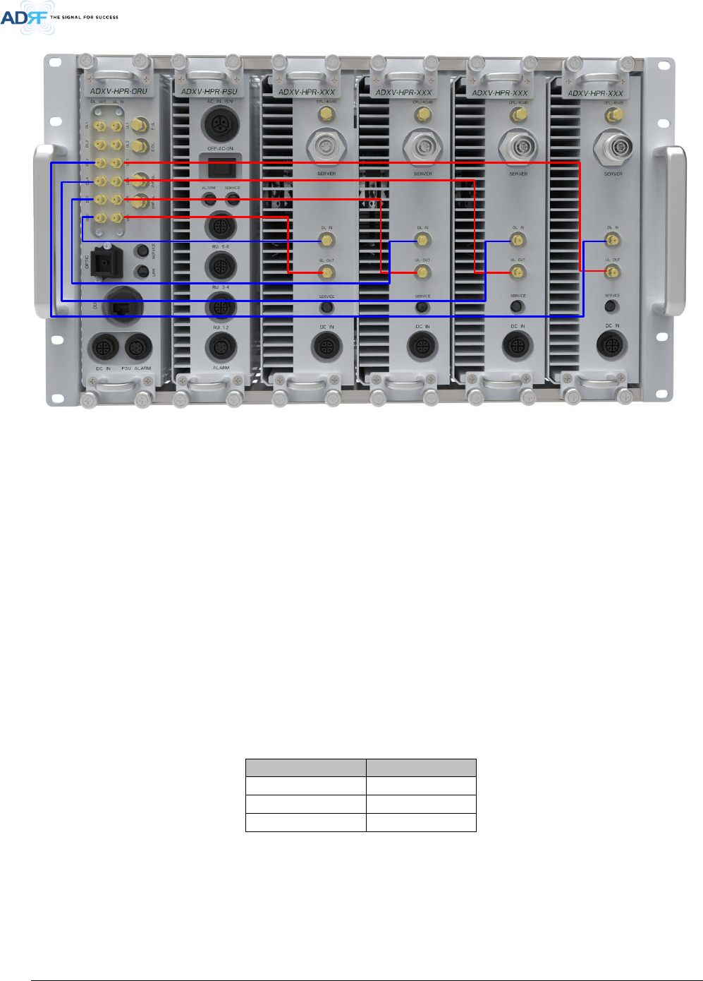
3.2.1.1 HPR ID numbering and RF line connection scheme
HPR ID right next to ADXV-HPR-ORU is HPR #1, HPR second next is HPR #2, the rest of HPR s’ ID numbering is in
the same order.
With RF connection between ADXV-HPR-ORU and HPR, it is necessary ADXV-HPR ID number should be equal to
DL/UL port number of ADXV-HPR-ORU because of ADXV-HPR ID management and normal serial communication.
Advanced RF Technologies, Inc.
31
HPR #1 HPR #2 HPR #3 HPR #4
Figure 3-16 ADXV-HPR ID numbering and RF connection between ADXV-HPR-ORU and ADXV-HPR
3.2.1.2 RF port
DL IN/UL OUT connect to ADXV-HPR-ORU’s DL port and UL port, it is necessary to connect UL’s port number
equal to DL’s because of serial communication with ADXV-HPR-ORU.
CPL (-40dB): DL output 40dB coupling
SERVER: DL output, UL input, Server Duplexer port
3.2.1.3 Power port
DC IN: Port for power supply (+27VDC) and communication with Controller inside PSU.
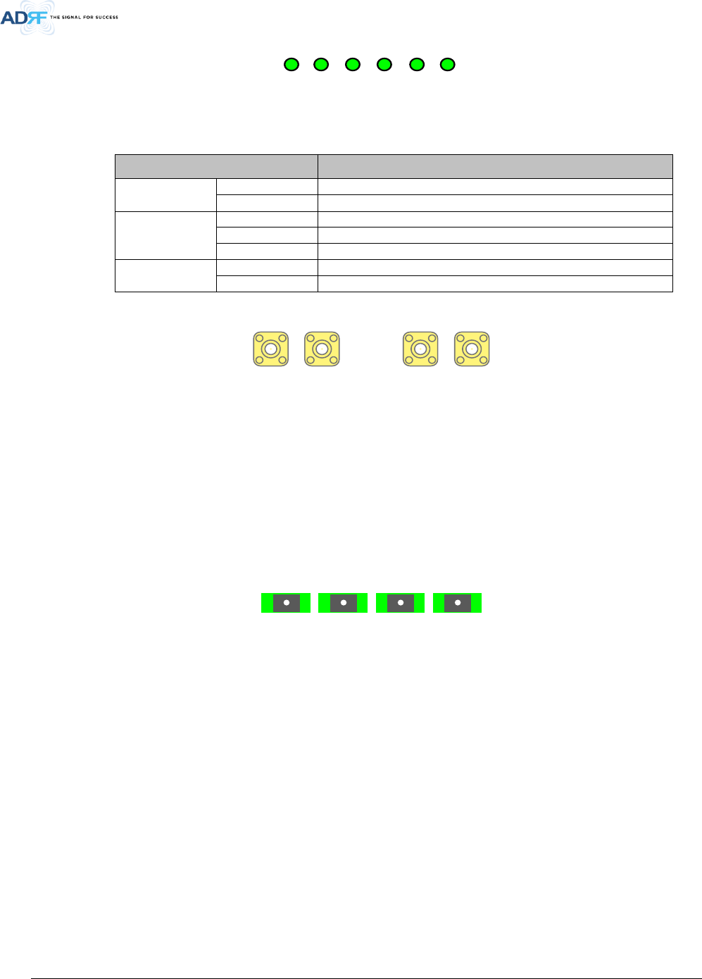
3.2.1.4 LED
LED color
Status
Green
Normal
Yellow
Soft fail
Red
Hard fail
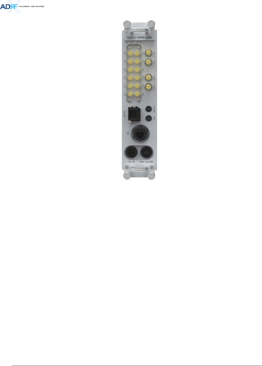
3.2.2 Optical Remote Unit (ADXV-HPR-ORU)
Advanced RF Technologies, Inc.
32
Figure 3-17 ADXV-HPR-ORU Front View
• Spec
- Size: 2.36 x 13.8 x 10.3 inches
- Weight: 11.02lbs
3.2.2.1 Front port
DL1-DL6: DL port connect to ‘DL IN’ of ADXV-HPR (Remote Module) (see 3.2.1.1)
UL1-UL6: UL port connect to ‘UL OUT’ of ADXV-HPR (Remote Module)(see 3.2.1.1)
E-DL/E-UL ports connect to external splitter for extension of band RM
VHF-DL/VHF-UL ports connect to the ADXV VHF/UHF RM
OPTIC port connects with optic line with waterproof optical connector (provided by ADRF)
3.2.2.2 Rear port
DC IN port connects to PSU’s ADXV-HPR-ORU port.
PSU ALARM port connects to PSU’s ALARM port.
GUI port for connection to Lap top.
FAN port for connection to FAN unit.
3.2.2.3 LED
Advanced RF Technologies, Inc.
33
LED
LED color
Status
Link
Green
Link normal
Yellow
Link fail
Service
Green
Normal
Yellow
Soft fail
Red
Hard fail
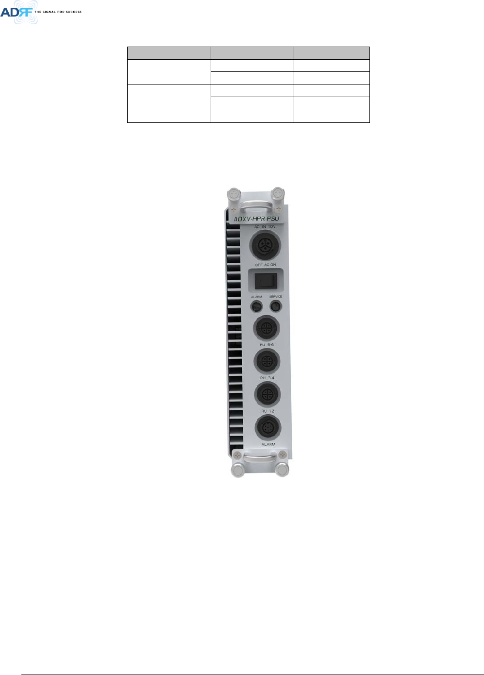
3.2.3 PSU (ADXV-HPR-PSU)
Figure 3-18 ADXV-HPR-PSU Front View
• Spec
- Size: 2.36 x 17.8 x 10.3inches
- Weight: 11.02lbs for AC/DC PSU
3.2.3.1 Port
ADXV-HPR1-ADXV-HPR4 ports connect respectively to ADXV-HPR’s front port.
ADXV-HPR-ORU port connects to ADXV-HPR.
ALARM port connects to ‘PSU ALARM’ port of ADXV-HPR-ORU ALARM port
AC IN 110V port connects to AC 110V
Advanced RF Technologies, Inc.
34
3.2.3.2 LED
LED
LED color
Status
ALARM
Green
Normal
Yellow
Link fail
SERVICE
Green
Normal
Yellow
Soft fail
Red
Hard fail
3.2.3.3 AC Switch
The ADXV-HPR is operated at 110 AC.
(WARNING: The AC switch must be set to OFF before cable connection to avoid equipment damage and
personal injury.)
(WARNING: To avoid damage, be sure 110V AC for operation of ADXV-HPR.)
(CAUTION: DOUBLE POLE/NEUTRAL FUSING.)
The procedure for connecting ADXV-HPR
AC S/W OFF
AC cable connection
Optic connection
RF cable connection
AC S/W ON
4. CABLE CONNECTION
4.1 Head End Connection Diagrams
Figure 4-1 HE Cable connection (4 ADXV-H-POIs, 2 ADXV-H-ODUs)
AAI
SERVICE
HOST
ADXV-H-NMS-DC
LAN1
LAN0
LAN0
RTN
-48V
DC IN
REMOTE
01
02
03
04
05
P(+)
LINK
N(-)
UL IN
DL OUT
SERVICE
E911
DL/UL
ADXV-H-POI-X
ADXV-H-POI-X
UL
DL/UL
BTS
BTS
UL IN
DL OUT
SERVICE
E911
DL/UL
ADXV-H-POI-X
ADXV-H-POI-X
UL
DL/UL
BTS
BTS
UL IN
DL OUT
SERVICE
E911
DL/UL
ADXV-H-POI-X
ADXV-H-POI-X
UL
DL/UL
BTS
BTS
UL IN
DL OUT
SERVICE
E911
DL/UL
ADXV-H-POI-X
ADXV-H-POI-X
UL
DL/UL
BTS
BTS
UL IN
DL OUT
SERVICE
E911
DL/UL
ADXV-H-POI-X
ADXV-H-POI-X
UL
DL/UL
BTS
BTS
DL IN 1
SERVICE
ADXV-H-CHC-88-DL
DL IN7 DL IN6 DL IN5 DL IN4 DL IN3 DL IN2 DL IN1DL IN8
DL OUT7DL OUT6DL OUT5DL OUT4DL OUT3DL OUT2DL OUT1 DL OUT8
ADXV-H-CHC-88-DL
DL IN 1
SERVICE
ADXV-H-CHC-88-UL
DL IN7 DL IN6 DL IN5 DL IN4 DL IN3 DL IN2 DL IN1
DL IN8
DL OUT7DL OUT6DL OUT5DL OUT4
DL OUT3DL OUT2DL OUT1 DL OUT8
ADXV-H-CHC-88-UL
VHF UL
ADXV-H-ODU-4
ADXV-H-ODU-4
UL OUT
DL IN VHF UL
PWRLD
PD4PD3PD2PD1
VHF DL
OPTIC1 OPTIC2 OPTIC3 OPTIC4
VHF UL
ADXV-H-ODU-4
ADXV-H-ODU-4
UL OUT
DL IN VHF UL
PWRLD
PD4PD3PD2PD1
VHF DL
OPTIC1 OPTIC2 OPTIC3 OPTIC4
Advanced RF Technologies, Inc.
35
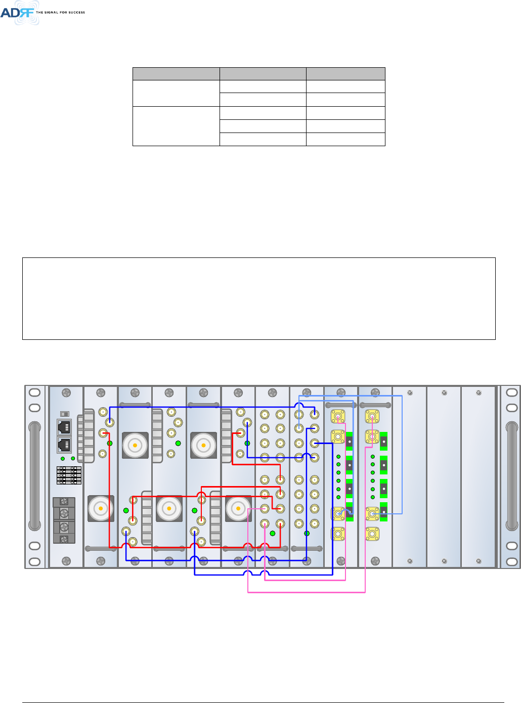
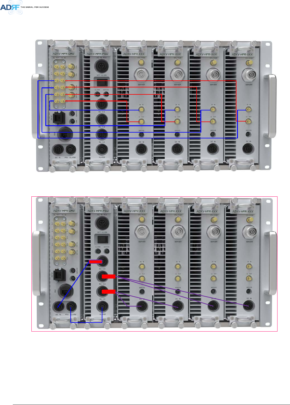
4.2 Remote Unit Connection Diagrams
HPR #1 HPR #2 HPR #3 HPR #4
HPR #1 HPR #2 HPR #3 HPR #4
PSUORU
PSUORU
Figure 4-2 ADXV-HPR 4ands connection
Advanced RF Technologies, Inc.
36
5. MOUNTING METHOD
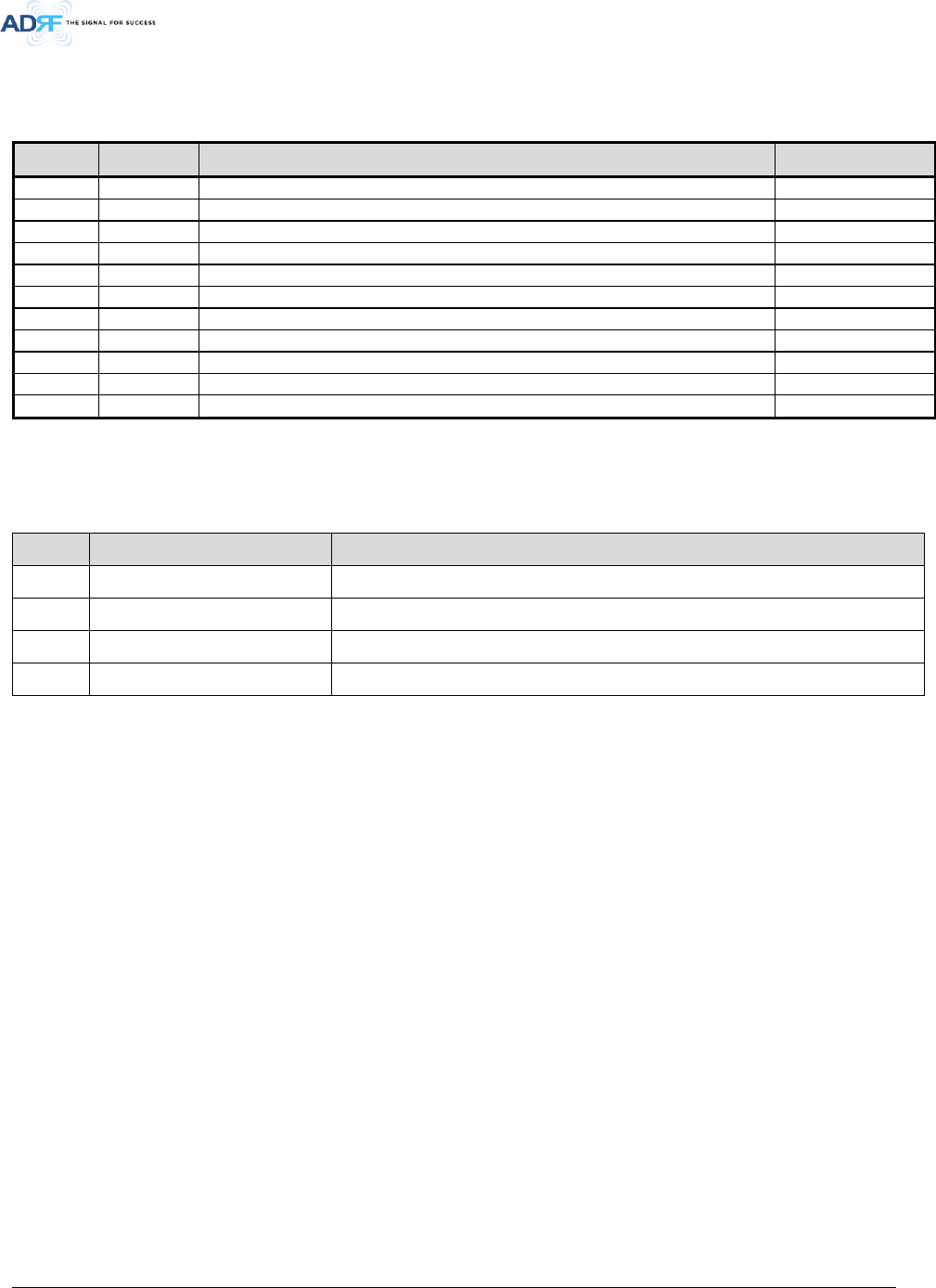
5.1 Head End
5.1.1 Rack Mount
Figure 5-1 HE Rack Mount (Front & Rear view)
SD SD
AUX 1
AUX 3
AUX 5
AUX 7
AUX 1
AUX 3
AUX 5
AUX 7
AAI
SERVICE
HOST
ADXV-H-NMS-DC
LAN1
LAN0
LAN0
RTN
-48V
DC IN
REMOTE
01
02
03
04
05
P(+)
LINK
N(-)
UL IN
DL OUT
SERVICE
E911
DL/UL
ADXV-H-POI-X
ADXV-H-POI-X
UL
DL/UL
BTS
BTS
UL IN
DL OUT
SERVICE
E911
DL/UL
ADXV-H-POI-X
ADXV-H-POI-X
UL
DL/UL
BTS
BTS
UL IN
DL OUT
SERVICE
E911
DL/UL
ADXV-H-POI-X
ADXV-H-POI-X
UL
DL/UL
BTS
BTS
UL IN
DL OUT
SERVICE
E911
DL/UL
ADXV-H-POI-X
ADXV-H-POI-X
UL
DL/UL
BTS
BTS
UL IN
DL OUT
SERVICE
E911
DL/UL
ADXV-H-POI-X
ADXV-H-POI-X
UL
DL/UL
BTS
BTS
DL IN 1
SERVICE
ADXV-H-CHC-88-DL
DL IN7 DL IN6 DL IN5 DL IN4 DL IN3 DL IN2 DL IN1DL IN8
DL OUT7DL OUT6DL OUT5DL OUT4DL OUT3DL OUT2DL OUT1 DL OUT8
ADXV-H-CHC-88-DL
DL IN 1
SERVICE
ADXV-H-CHC-88-UL
DL IN7 DL IN6 DL IN5 DL IN4 DL IN3 DL IN2 DL IN1DL IN8
DL OUT7DL OUT6DL OUT5DL OUT4DL OUT3DL OUT2DL OUT1 DL OUT8
ADXV-H-CHC-88-UL
VHF UL
ADXV-H-ODU-4
ADXV-H-ODU-4
UL OUT
DL IN VHF UL
PWRLDPD4
PD3PD2PD1
VHF DL
OPTIC1 OPTIC2 OPTIC3 OPTIC4
Advanced RF Technologies, Inc.
37
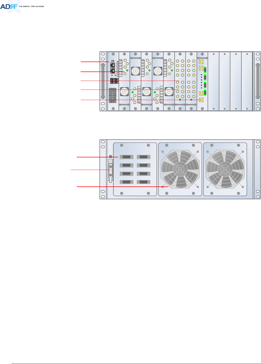
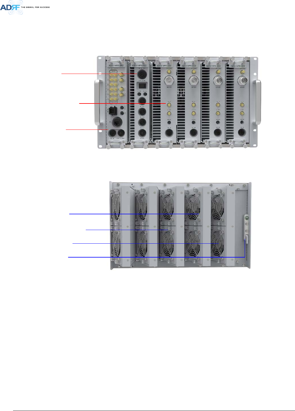
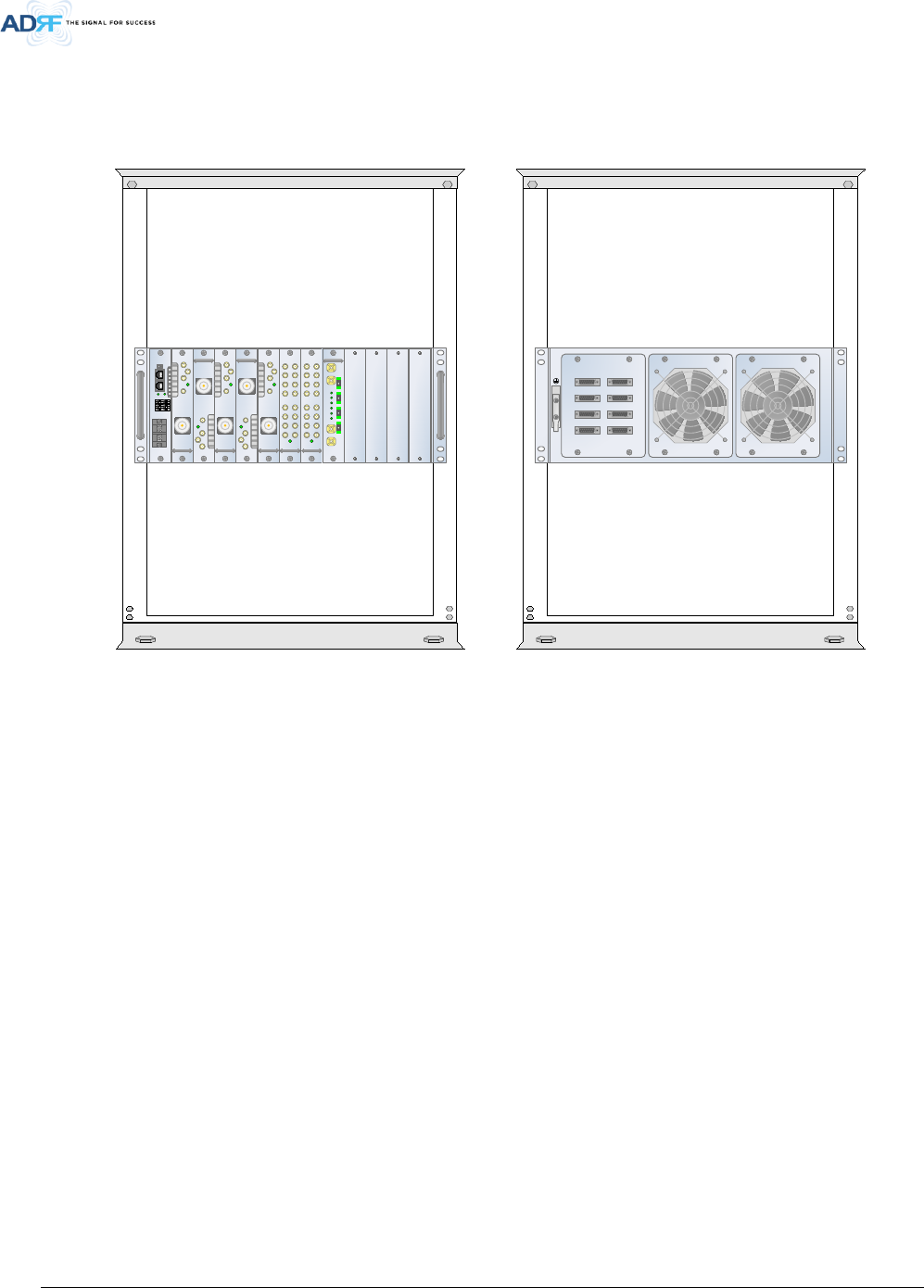
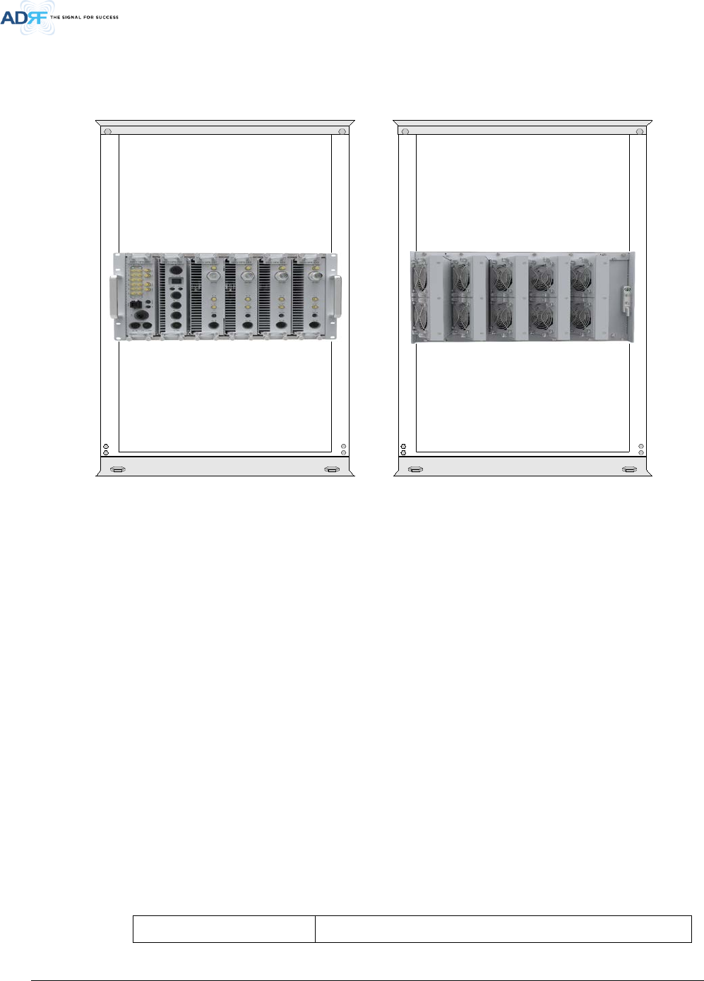
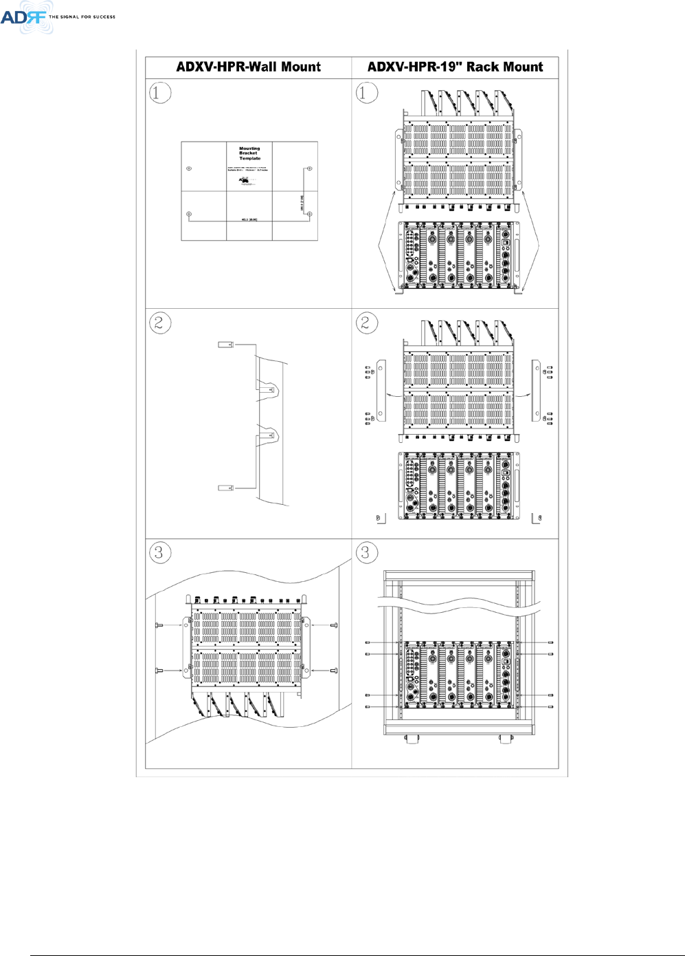
5.2 ADXV-HPR
5.2.1 Rack Mount
SD SD
Figure 5-2 ADXV-HPR Rack Mount Front and Rear View
6. INSTALLATION
6.1 Pre-Installation Inspection
Please follow these procedures before installing ADXV equipment:
o Verify the number of packages received against the packing list.
o Check all packages for external damage; report any external damage to the shipping carrier. If
there is damage, a shipping agent should be present before you unpack and inspect the contents
because damage caused during transit is the responsibility of the shipping agent.
o Open and check each package against the packing list. If any items are missing, contact ADRF
customer service.
o If damage is discovered at the time of installation, contact the shipping agent.
o Verify the AC voltage with DVM (Volt meter) is 110V AC. Incorrect AC voltage can damage the ADXV
equipment.
o This power of this system shall be supplied through wiring installed in a normal building. If powered
directly from the mains distribution system, it shall be used additional protection, such as
overvoltage protection device.
o Over voltage category(OVC) & Pollution degree(PD)
Over voltage category (OVC) OVC II

Advanced RF Technologies, Inc.
38
Pollution degree (PD) PD2
6.2 ADXV Installation Procedure
6.2.1 HE Installation Procedure
CAUTION: ADXV- HE should be installed inside building only.
6.2.1.1 Installing a ADXV- HE in a rack
The ADXV HE chassis mounts in a standard 19” (483mm) equipment rack. Allow clearance of 3” (76mm) at the
front and rear, and 2” (51mm) on both sides for air circulation. No top or bottom clearance is required.
• Consideration:
- Eight mounting holes (two holes at each corner of ADXV-HE rack) are to attach it to the 19” rack.
The ADXV HE must be securely attached to a rack that can support the weight of the ADX.
• Mount procedure
- The following steps should be followed while mounting the ADXV HE
Verify that the HE and Mounting holes are in good condition
Set the ADXV HE against the 19”rack and secure the unit with screws
Verify that ADXV HE is securely attached
Connect the GND cable
Connect the RF cable
Connect the Power
Connect the Optic cable
Advanced RF Technologies, Inc.
39
Figure 6-1 HE Installation Procedure

Advanced RF Technologies, Inc.
40
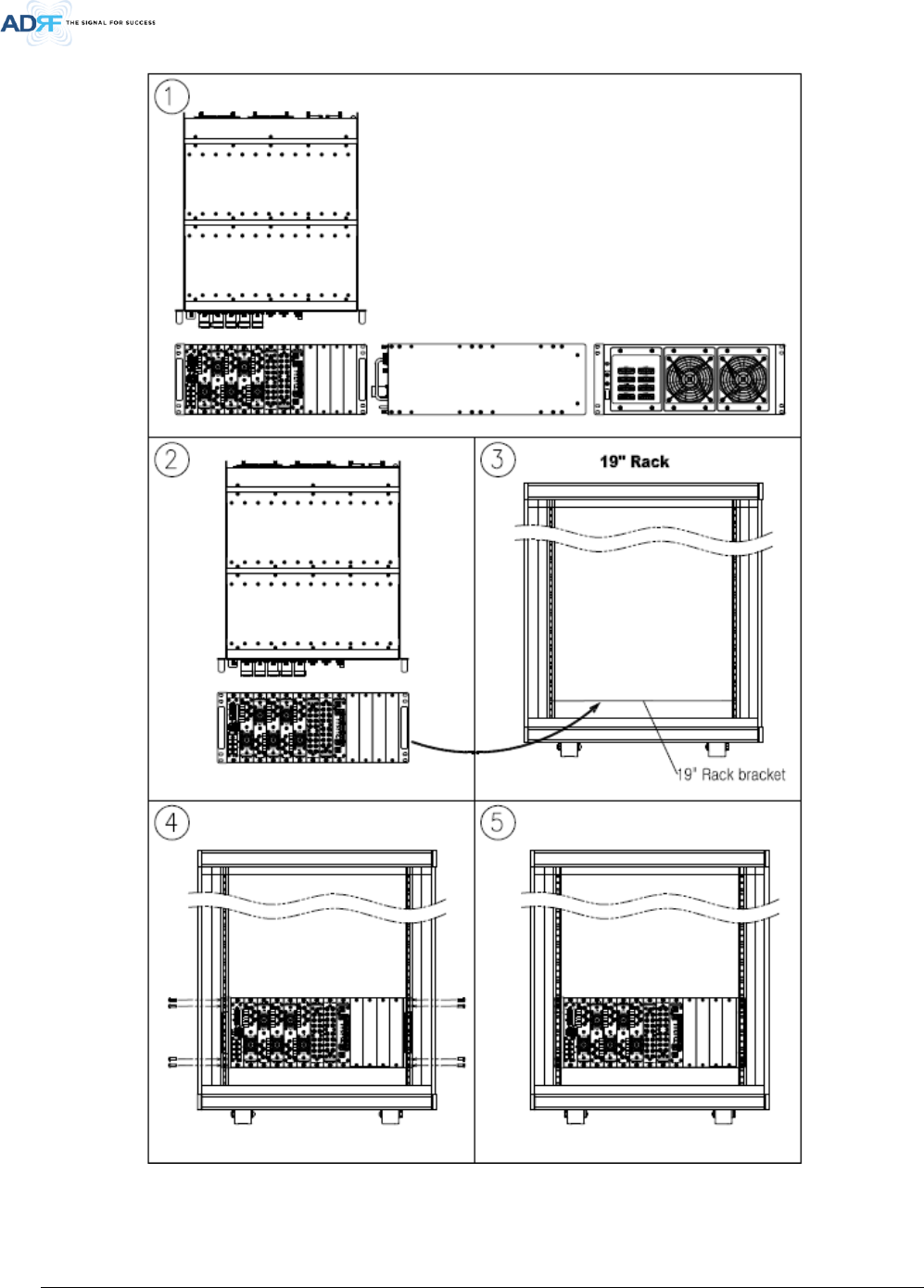
6.2.2 ADXV-HPR Installation Procedure
The ADXV-HPR chassis mounts in a standard 19” (483mm) equipment rack. Allow clearance of 3” (76mm) at the
front and rear, and 2” (51mm) on both sides for air circulation. No top or bottom clearance is required.
• Consideration:
- Eight mounting holes (two holes at each corner of ADXV-HPR rack) are to attach it to the 19” rack.
The ADXV-HPR must be securely attached to a rack that can support the weight of the ADXV.
• Procedure
- The following steps should be followed while mounting the ADXV-HPR
Verify that the ADXV-HPR and Mounting holes are in good condition
Set the ADXV-HPR against the 19”rack and secure the unit with screws
Verify that ADXV-HPR is securely attached
Connect the GND cable
Connect the RF coaxial cable
Connect the Power
Connect the Optic cable
Advanced RF Technologies, Inc.
41
Figure 6-2 ADXV-HPR Installation Procedure
Advanced RF Technologies, Inc.
42
6.2.3 RF coaxial cable and antenna connection
> The coaxial cables which are connected to antenna port of ADXV-HPR. Before connection, check the
VSWR value of coaxial cable whether it is within specification using Site master.
> At this time, check if the Return loss have above 15dB or VSWR have below 1.5
> The part of antenna connection fasten to port not to be loosed and not to be injected the dusty and
insects
> The antenna connected to ADXV-HPR is only serviced in in-building
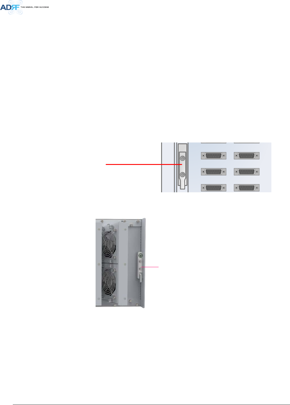
6.3 Grounding
A ground cable is included in the box. The grounding terminals are located at the rear of the ADXV HE and ADXV-
HPR. The grounding cable should be properly connected before powering on the equipment.
Figure 6-3 HE Ground Cable Connection, Protective Earthing Conductor (HE chassis rear side)
Ground Terminal
Figure 6-4 ADXV-HPR Ground Cable Connection, Protective Earthing Conductor (ADXV-HPR chassis rear
side)
Round terminals located on the side of a 1.25mm²(16AWG)or more wires Using permanently connected to
earth(Protective earthing conductor).
U
AUX 3
AUX 5
AUX 7
U
AUX 3
AUX 5
AUX 7
U ot
Fan Unit
Ground Terminal

Advanced RF Technologies, Inc.
43
6.4 Optic Port Cleaning
• We recommend cleaning optic connector using a dry optical cleaning swab or tissue in a dry environment as
needed. We recommend cleaning the optic connectors only if the expected optic loss is higher than the loss
reported in the Web-GUI by 1.5dBo. (Figure 6-5)
• When optic connector are not in use, the port should be covered with a protective dust cap. (Figure 6-6)
Figure 6-5 Optic Connector Cleaning (left) and Optic Port Cleaning (right)
Figure 6-6 SC/APC Optic Connector Dust Cap
Advanced RF Technologies, Inc.
44
7. WEB-GUI
7.1 Web-GUI Setup
The Web-GUI allows the user to communicate with the DAS system either locally or remotely. To connect to
the DAS system locally, you will need a laptop with an Ethernet port and a RJ-45 crossover cable. To connect to the
DAS system remotely, you will need to have an active internet connection and the ADXV system must have and
external modem box connected to the ADXV.
7.1.1 DAS system/PC Connection Using Web-GUI
• Verify that your Local Area Connection is set to Obtain an IP address automatically under the Internet Protocol
(TCP/IP) properties
- If you are connecting to the unit remotely (use of a modem), then skip this and next step.
• Connect the RJ-45 crossover cable between the laptop’s Ethernet port and the repeater’s Ethernet port
• Launch an Internet Browser
• Type the following IP address into the address bar of Microsoft Internet Explorer: http://192.168.63.1
- If you are connecting to the unit remotely, then type the IP address of the modem to connect to
the unit
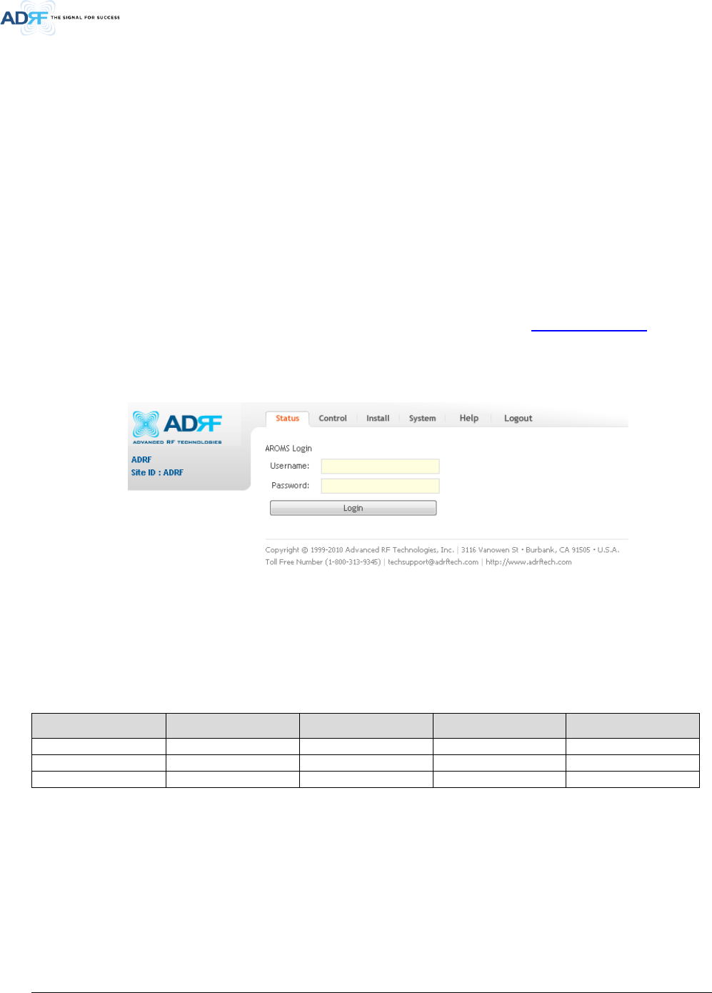
• The following login screen will appear:
Figure 7-1 Login screen
If you are not the Administrator, please type in your assigned username & password which you should have
received from the Administrator.
Table 7-1 Account Information for Login
Account type Show items Control Items Default ID Default Password
Administrator
all Items
all items
admin
admin
User
restricted items
restricted items
adrf
adrf
Guest
restricted items
read-only
guest
guest
Advanced RF Technologies, Inc.
45
7.2 Administrator/User Mode
7.2.1 Common
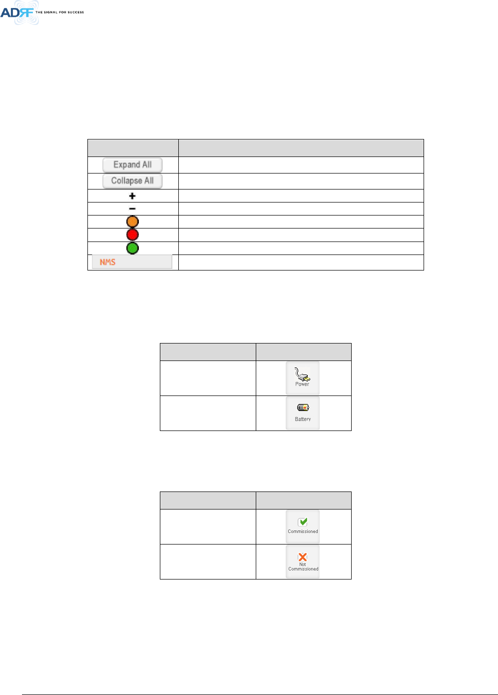
7.2.1.1 Navigation Tree
The navigation tree located on the left hand side of the Web-GUI allows the user to switch between the
various modules that are connected to the system.
Table 7-2 Navigation tree
Parameters Description
Expands the entire navigation tree
Collapses the entire navigation tree
The module has the expandable subordinate modules
The branch is currently expanded
The module has soft fail alarm
The module has hard fail alarm
The module has no alarms (normal)
The selected module will have orange colored text
7.2.1.2 Power Status
Display the power source that is currently being used.
Table 7-3 Power Supply Status
Input Power Status Display Image
AC
Battery
7.2.1.3 Commissioning Status
Display whether or not the module has successfully been commissioned.
Table 7-4 Commissioning ICON
Status Display Image
Commissioned
Not-Commissioned
7.2.1.4 Information

Advanced RF Technologies, Inc.
46
Figure 7-2 ADXV General Information
• Information: Displays the serial number, latitude/longitude, firmware version of selected module, and Web GUI
version of the NMS.
• Location: Displays the address where the ADXV is installed.
• Description: Displays the description of selected module. The description of each module can be edited from
the Install tab. It is recommended to use the location of the module as the description. This description
information can be seen when hovering over the device tree in order to easily identify each component.
• Technical Support: Displays ADRF’s Technical Support contact information.
• Installer Contact Info: Displays the contact information of the installer.
Advanced RF Technologies, Inc.
47
7.2.2 Status Tab
7.2.2.1 Status – NMS
The NMS Status page provides an overall view of how the system is performing. From the NMS Status page, the
user can see what modules are connected to ADXV-HPR. In addition, the user can see if any alarms are present in
the system and also the commissioning status of each module.
7.2.2.1.1 System Summary
The Summary section provides the user with the number of components physically connected, the number of
soft/hard/link fails present in the system, and also the number of commissioned and non-commissioned componnets.
Table 7-5 System Summary Description
Parameters Description
Connected Display the number of modules physically connected to ADXV-HPR
Soft Fail Display the number of soft fail present on each module
Hard Fail Display the number of hard fail present on each module
Link Fail Display the number of link fail present on each module
Not Commissioned Display the number of non-commissioned or commission failed module
Commissioned Display the number of successfully commissioned module
7.2.2.1.2 HE Alarm Status
Display the alarm status of each HE component.
7.2.2.1.3 HE Commissioning Status
Display commissioning status of each HE component.
7.2.2.1.4 Alarm
Displays alarm status of the NMS. If an alarm is present in the system, the color of the system alarm tab will
change according to the type of failure.
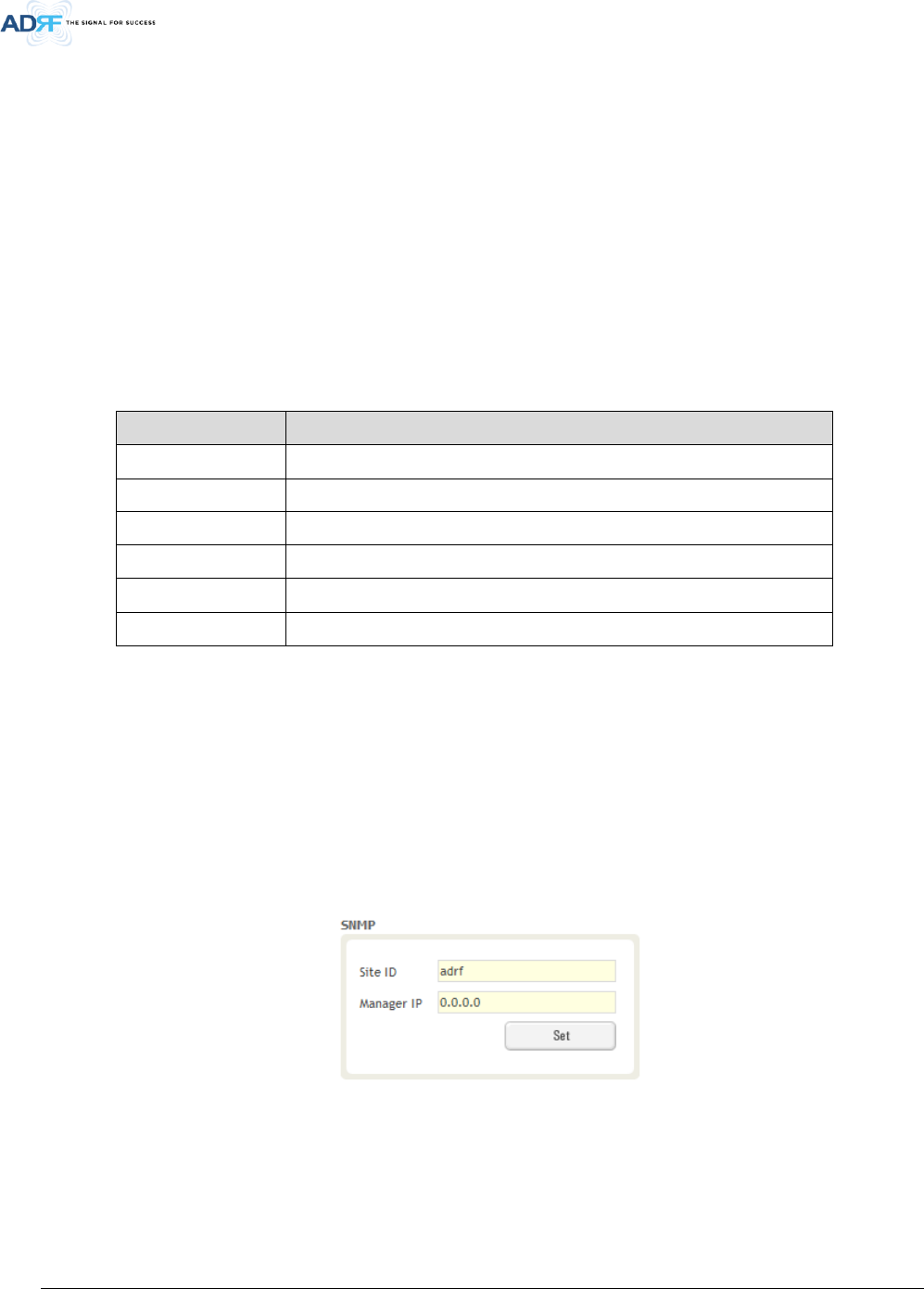
7.2.2.1.5 SNMP
Figure 7-3 SNMP (Install – NMS)
The SNMP section allows you to specify the Site ID and Manager IP. The Site-ID is the code that is used to
identify a particular module. The Manager IP field is where the user inputs the IP address of the NOC system that is
being used to monitor the SNMP traps.
7.2.2.1.6 Location
Advanced RF Technologies, Inc.
48
This section allows the user to input the latitude and the longitude of the repeater.
Figure 7-4 Location Setting (Install – NMS)
• Select N or S from the dropdown menu for Latitude
• Select E or W from the dropdown menu for Longitude
• Input the first 3 numbers of the latitude/longitude in the text area after the “+” and before the “.”
• Input the last 6 numbers of the latitude/longitude in the text area after the “.”
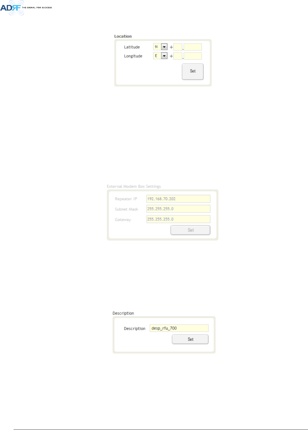
7.2.2.1.7 External Modem Box Settings
This section allows the user to specify an alternative IP, Subnet Mask, and Gateway settings. These settings are
enabled when the Host/Remote switch is set to the Remote position.
Figure 7-5 External Modem Box Setting (Install – NMS)
7.2.2.1.8 Description
This section allows the user to save the description of NMS.
Figure 7-6 Description (Install – NMS)
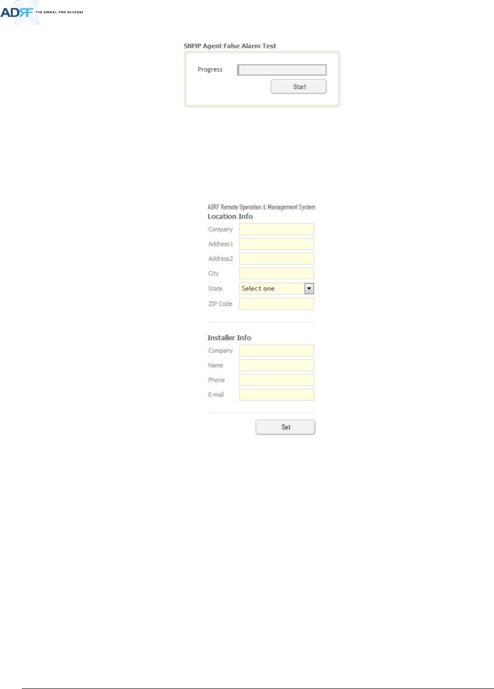
7.2.2.1.9 SNMP Agent False Alarm Test
This section allows the user to generate both soft and hard fail alarms. After alarms are generated, the NOC can
poll the ADXV to see if alarms are present. All alarms generated during this test are false alarms.
Advanced RF Technologies, Inc.
49
Figure 7-7 SNMP Agent False Alarm Test (Install – NMS)
7.2.2.1.10 Location Info / Installer Info
This section allows the user to specify the address of the repeater and also the information of the installer.
Figure 7-8 Location Info / Installer Info (Install – NMS)
Advanced RF Technologies, Inc.
50
7.2.2.1.11 Date & Time
This section allows the user to specify the current date and time.
Figure 7-9 Date & Time Setting (Install – NMS)
7.2.2.1.12 Description
This section allows the user to save the description of remote module.
Figure 7-10 Description (Install-Remote Module)
7.2.3 System
The System tab allows the user to perform firmware updates, upload closeout packages, view any changes to
the system, backup existing configuration, and add/remove user accounts, and change the login credentials of the
Administrator.
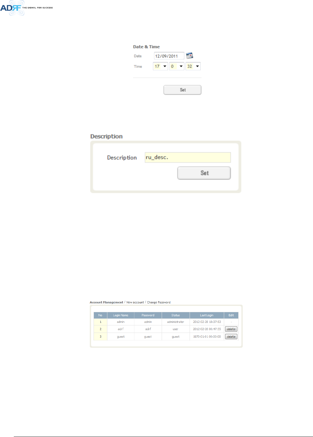
7.2.3.1 System: Account
7.2.3.1.1 System: Account - Account Management (Admin Only)
The Account Management section allows the Administrator to delete any user/guest account. Please note that
the Account Management section is only available if you are logged into the system as the Administrator. To delete
a user/guest account click on the Account Management link and under the Delete column, click on the delete button.
Figure 7-11 Account Management
7.2.3.1.2 System: Account - New Account (Admin Only)
The New account section allows the Administrator to create a new user/guest account. Please note that the
new account section is only available if you are logged into the system as the Administrator. To create a new
user/guest account click on the new account link and fill in the fields highlighted in yellow as shown below.

Advanced RF Technologies, Inc.
51
Figure 7-12 New Account
Advanced RF Technologies, Inc.
52
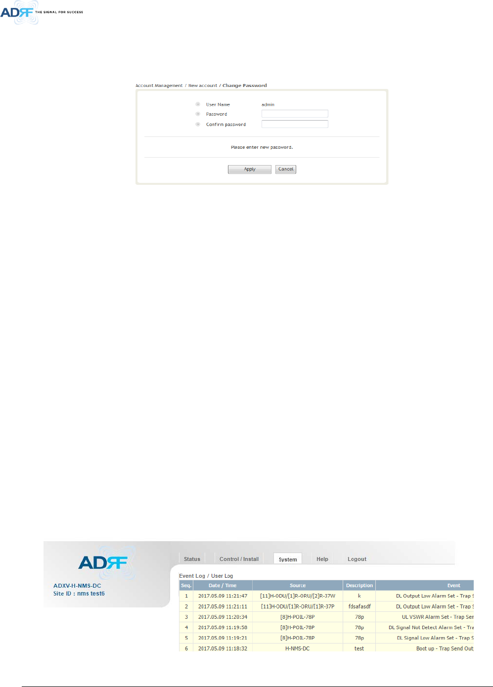
7.2.3.1.3 System: Account - Change Password
The Change Password section allows the current user who is logged into the system to change their login
credentials.
Figure 7-13 Change Password
7.2.3.2 System: Logs
7.2.3.2.1 System: Logs - Event Log
This section displays system events that have taken place. The Event Log displays who has made the changes,
the time and date of when the event took place, and what changes were made to the system. The System Log tracks
the following events:
• System Initiation
• Alarm Set
• Alarm Clear
7.2.3.2.2 System: Logs - User Log
This section tracks user activity within the system. The User Log displays who has made the changes, the time
and date of when the event took place, and what changes were made to the system. The User Log tracks the
following items:
• Log in / Log out activity
• Changes to gain/attenuation/output values
• System event generated by user(firmware update, backup/resote, create/delete account)
• DAS Navigation Tree Lock/Unlock
• Description change
• Repeater/installer information change
• Setting date/time
Figure 7-14 User Log
Advanced RF Technologies, Inc.
53
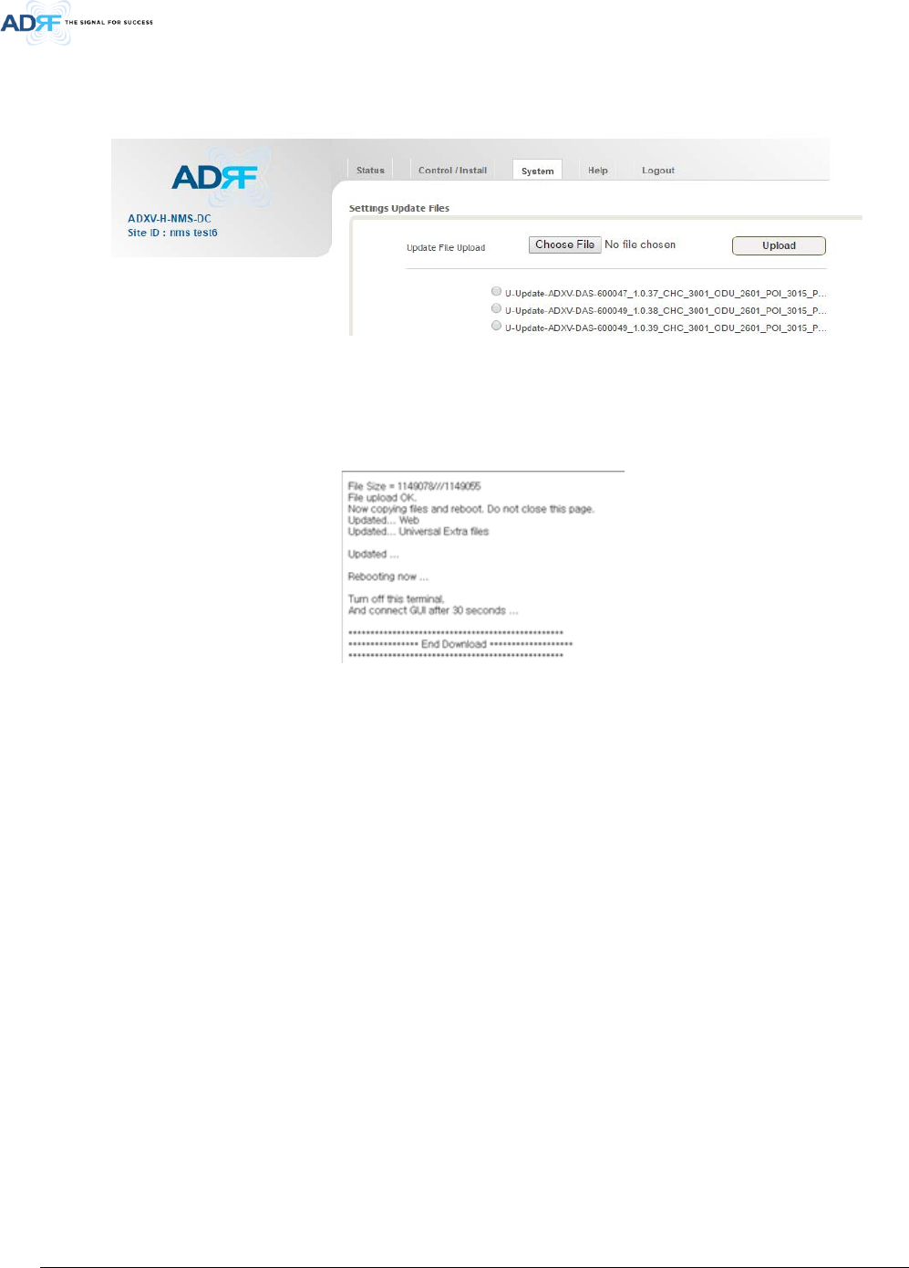
7.2.3.3 System: Update
• To perform a firmware update, click on the System:Update tab and the following screen will show up.
Figure 7-15 System update
• Click on the ‘Browse’ button and locate the firmware file.
• Click on the Update button to perform the firmware update.
• Once the firmware update is complete, the following message will appear.
Figure 7-16 Message after System update is complete
7.2.4 Help
If an internet connection is available, clicking on the Help Tab will redirect the user to our Technical Support
page.

Advanced RF Technologies, Inc.
54
Figure 7-17 Help
7.2.5 Logout
Clicking the Logout button will log the current user off the system.
7.3 Guest Mode
When logging into the system as a guest, the guest will only have read-only privileges and will not be able to
make any changes to the system.
Advanced RF Technologies, Inc.
55
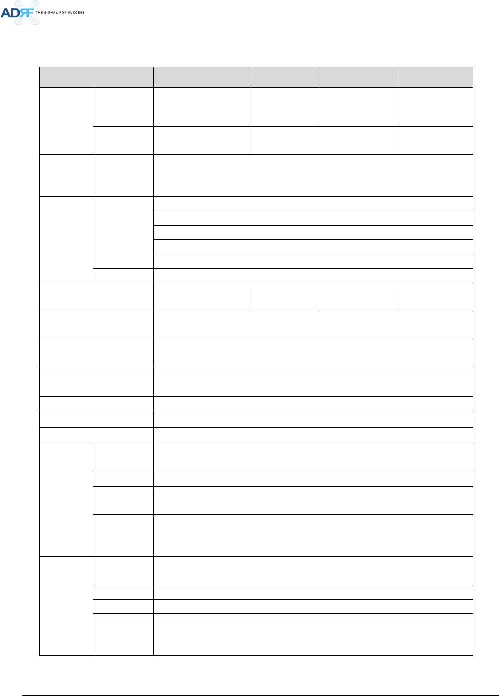
8. ADXV SYSTEM-WIDE SPECIFICATION
700LTE/S8C/PCS/AWS
Parameters 700MHz SMR800+CELL PCS AWS
Frequency
(Bandwidth)
Downlink Lower ABC+ Upper C
728-757MHz
862-894MHz
(32MHz)
1930-1995MHz
(65MHz)
2110-2180MHz
(70MHz)
Uplink Lower ABC+ Upper C
698-716, 776~787MHz
817-849MHz
(32MHz)
1850-1915MHz
(65MHz)
1710-1780MHz
(70MHz)
Input Power
Range @
POI
Power Mode +48~ 0dBm
System
Gain/
Nominal
pass band
gain
Downlink
-11~33dB/43dB (2Watt)
-11~37dB/37dB (5Watt)
-11~43dB/43dB (20Watt)
-11~46dB/45dB (30Watt)
-11~46dB/46dB (40Watt)
Uplink 0~30dB
Rated mean output power
(DL) 43dBm(20W) 43dBm(20W) 46dBm(40W) 46dBm(40Watt)
Maximum Composite
Output Power(UL) -15dBm
Noise Figure ≤ 5dB @maximum gain, Center Frequency
VSWR ≤ 1.3:1 @ BTS interface port
≤ 1.5:1 @ Internal interface port
Optical Loss 0~5dBo
System Delay < 2us
Spurious Meet FCC, 3GPP TS 36.104, 3GPP2 C.S0010-C
Dimension
(WXDXH)
Head End
Chassis 19in x 19.7 in x 7.0 inches
POI/POIL 1.3in x 17.0 in x 6.85 inches
ADXV-HPR
Chassis 19in x 15.0 in x 10.5 inches
ADXV-
HPR(Remote
Unit)
2.75in x 17.8 in x 10.3 inches
Weight
Head End
Chassis 20.9 lbs
POI 6.17 lbs
POIL 5.00 lbs
ADXV-
HPR(Remote
Unit) Chassis
17.60 lbs
Advanced RF Technologies, Inc.
56
ADXV-
HPR(Remote
Unit)
13.22 lbs
Operating Temperature -22 - 140 F(-30~60°C)
Operating Humidity 5~90%RH
Power
Supply
Head-End -48V DC
110/220V, 50-60Hz(optional) with battery backup function
ADXV-HPR 110/220V, 50-60Hz
-48V DC(optional)
Power
consumption
ADXV-H-NMS-
AC
8.85 Watt
ADXV-H-ODU-
4
7.47 Watt
ADXV-H-POI 7.20 Watt
ADXV-H-POIL 6.45 Watt
ADXV-HPR-
PSU-AC
5.4 Watt
ADXV-HPR-
ORU
109 Watt
ADXV-HPR-
437F
129 Watt
ADXV-HPR-
43S8C
145 Watt
ADXV-HPR-
46P
264 Watt
ADXV-HPR-
46A
259 Watt
Network Management
System Ethernet(RJ45)
RF
connector
POI DIN(Female)
POIL 4.3-10(Female)
ADXV-
HPR(Remote
Unit)
4.3-10(Female)
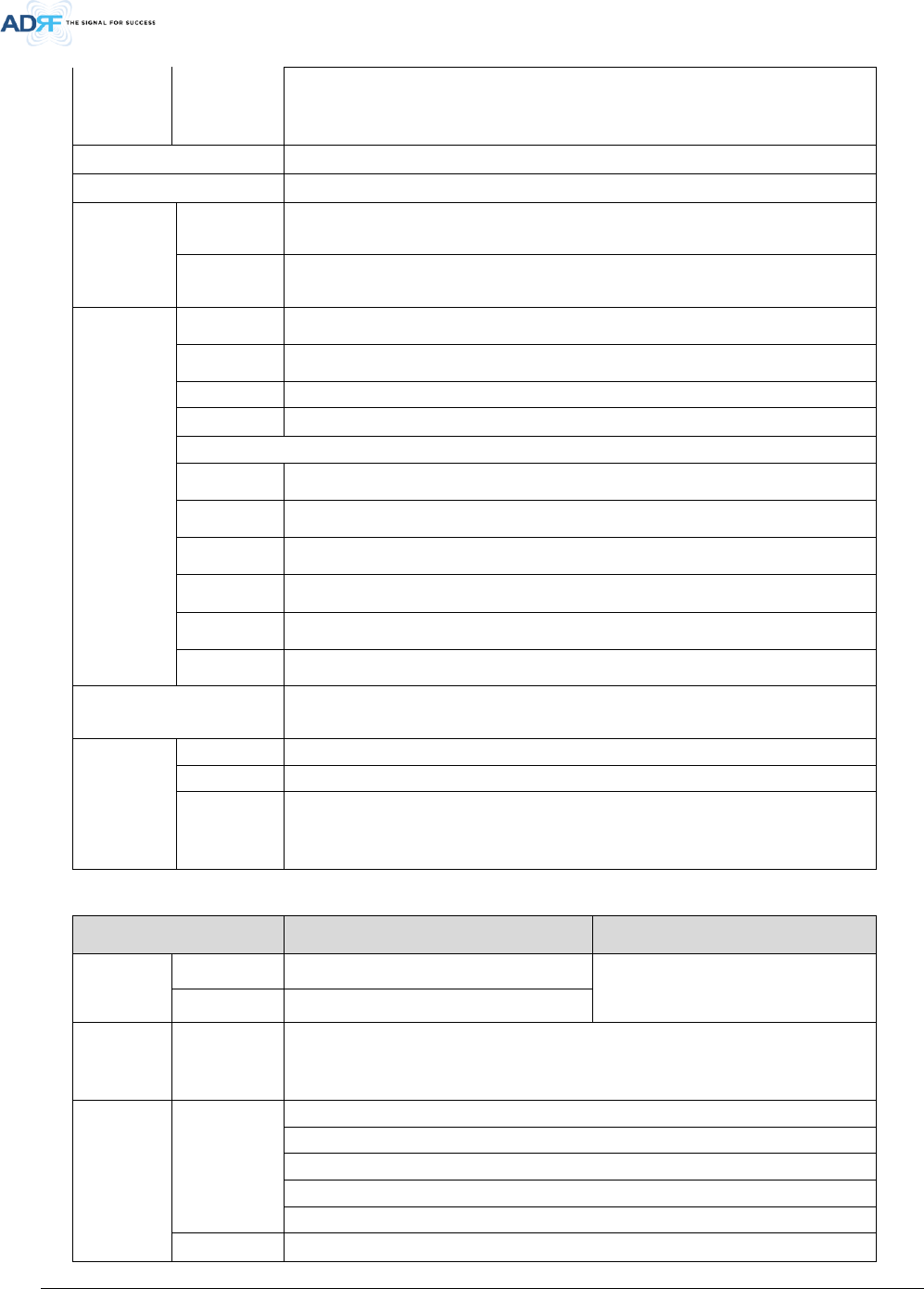
WCS/BT
Parameters WCS BRS TD-LTE
Frequency
(Bandwidth)
Downlink 2350~2360MHz 2496~2690MHz(FCC)
2500~2690MHz(IC)
Uplink 2305~2315MHz
Input Power
Range @
POI
Power Mode +48~ 0dBm
System
Gain/
Nominal
pass band
gain
Downlink
-11~33dB/43dB (2Watt)
-11~37dB/37dB (5Watt)
-11~43dB/43dB (20Watt)
-11~46dB/45dB (30Watt)
-11~46dB/46dB (40Watt)
Uplink 0~30dB
Advanced RF Technologies, Inc.
57
Rated mean output power
(DL) 45dBm(30Watt) 46dBm(40W)
Maximum Composite
Output Power(UL) -15dBm
Noise Figure ≤ 5dB @maximum gain, Center Frequency
VSWR ≤ 1.3:1 @ BTS interface port
≤ 1.5:1 @ Internal interface port
Optical Loss 0~5dBo
System Delay < 2us
Spurious Meet FCC, 3GPP TS 36.104, 3GPP2 C.S0010-C
Dimension
(WXDXH)
Head End
Chassis 19in x 19.7 in x 7.0 inches
POI/POIL 1.3in x 17.0 in x 6.85 inches
ADXV-HPR
Chassis 19in x 15.0 in x 10.5 inches
ADXV-
HPR(Remote
Unit)
2.75in x 17.8 in x 10.3 inches
Weight
Head End
Chassis 20.9 lbs
POI 6.17 lbs
POIL 5.00 lbs
ADXV-
HPR(Remote
Unit) Chassis
17.60 lbs
ADXV-
HPR(Remote
Unit)
13.22 lbs
Operating Temperature -22 - 140 F(-30~60°C)
Operating Humidity 5~90%RH
Power
Supply
Head-End -48V DC
110/220V, 50-60Hz(optional) with battery backup function
ADXV-HPR 110/220V, 50-60Hz
-48V DC(optional)
Power
consumption
ADXV-H-NMS-
AC
8.85 Watt
ADXV-H-ODU-
4
7.47 Watt
ADXV-H-POI 7.20 Watt
ADXV-H-POIL 6.45 Watt
ADXV-HPR-
PSU-AC
5.4 Watt
ADXV-HPR-
ORU
109 Watt
ADXV-HPR-
45W
255 Watt

Advanced RF Technologies, Inc.
58
ADXV-HPR-
46BT
264 Watt
Network Management
System Ethernet(RJ45)
RF
connector
POI DIN(Female)
POIL 4.3-10(Female)
ADXV-
HPR(Remote
Unit)
4.3-10(Female)
"The Manufacturer's rated output power of this equipment is for single carrier operation. For situations
when multiple carrier signals are present, the rating would have to be reduced by 3.5 dB, especially where
the output signal is re-radiated and can cause interference to adjacent band users. This power reduction
is to be by means of input power or gain reduction and not by an attenuator at the output of the device."
Advanced RF Technologies, Inc.
59
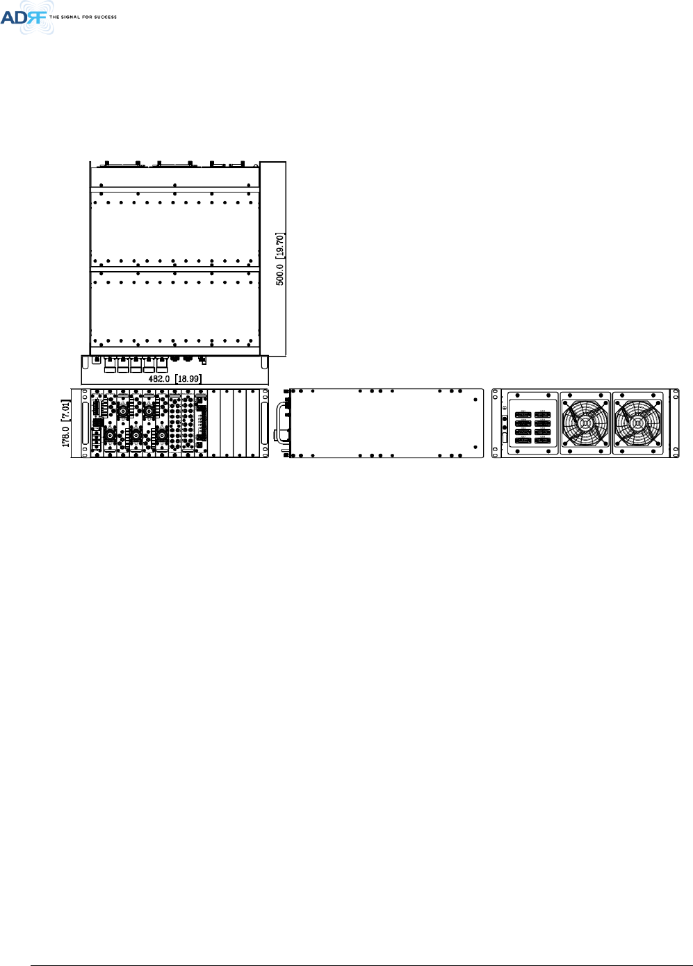
9. MECHANICAL DRAWING
9.1 HE
Figure 9-1 HE Drawing
Advanced RF Technologies, Inc.
60
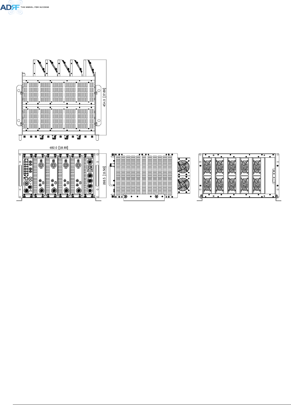
9.2 ADXV-HPR
Figure 9-2 ADXV-HPR Drawing