ADRF KOREA PSR-78-9533B Repeater User Manual AXMS8C 9543 ICS X MANUAL
ADRF KOREA, Inc. Repeater AXMS8C 9543 ICS X MANUAL
PSR-78-9533B_User Manual_v0.3_B9B_Rev.1

Advanced RF Technologies, Inc.
ii
Information in this document is subject to change without notice.
Advanced RF Technologies, Inc. 1996-2016.
All rights reserved.
Please send comments to:
E-Mail: info@adrftech.com
Phone: (818) 840-8131
(800) 313-9345
Fax: (818) 840-8138
Address:
Advanced RF Technologies, Inc.
Attention: Technical Publications Department
3116 Vanowen St.
Burbank, CA 91505
USA
www.adrftech.com
Advanced RF Technologies, Inc.
iii
REVISION HISTORY
CHANGE LIST
Version Change list Contents
Version Author Descriptions Date
0.1
ADRF
Initial Release
11/18/2016
0.2
Ck Jo
Revision Update
01/17/2017

Advanced RF Technologies, Inc.
iv
TABLE OF CONTENTS
1. Introduction ........................................................................................................................................................ 9
1.1 Highlights ..................................................................................................................................................... 9
1.2 Parts List..................................................................................................................................................... 10
1.3 Quick View ................................................................................................................................................. 11
1.4 Warnings and Hazards ............................................................................................................................... 12
2. Overview ........................................................................................................................................................... 17
2.1 LED ............................................................................................................................................................. 17
2.2 Host / Remote Switch ................................................................................................................................ 17
2.3 Cable Connection ....................................................................................................................................... 18
2.3.1 AC Power ............................................................................................................................................ 18
2.3.2 External Alarm .................................................................................................................................... 19
2.3.3 RF ........................................................................................................................................................ 20
2.3.4 Back Up Battery Port .......................................................................................................................... 21
2.3.5 Grounding ........................................................................................................................................... 22
2.3.6 Ethernet Port ...................................................................................................................................... 22
3. Alarms ............................................................................................................................................................... 23
3.1 Message Board Alarms and Notifications .................................................................................................. 23
3.2 Alarms ........................................................................................................................................................ 23
3.3 External Alarms .......................................................................................................................................... 24
3.3.1 External Alarm Output interface ........................................................................................................ 24
3.3.2 External Alarm Input interface ........................................................................................................... 25
4. Installation ........................................................................................................................................................ 26
4.1 Installation Procedures .............................................................................................................................. 26
4.1.1 Wall Mount Procedure ....................................................................................................................... 26
4.2 Antenna Separation/Isolation .................................................................................................................... 27
5. PSR-78-9533 Web-GUI Setup ............................................................................................................................ 29
5.1 Repeater/PC Connection Using Web-GUI .................................................................................................. 29
5.2 Status Tab .................................................................................................................................................. 30
5.2.1 Band Info ............................................................................................................................................ 31
5.2.2 Power & Gain ...................................................................................................................................... 31
5.2.3 Alarms ................................................................................................................................................. 32
5.2.4 Repeater Info / Repeater Location / Technical Support / Installer Contact Info ................................ 32
5.3 Control Tab ................................................................................................................................................ 33
5.3.1 General Setting ................................................................................................................................... 34
5.3.2 System ................................................................................................................................................ 34
5.3.3 Manual Gain Control .......................................................................................................................... 34
5.3.4 Alarm Settings .................................................................................................................................... 35
5.4 Install Tab ................................................................................................................................................... 36
5.4.1 Install .................................................................................................................................................. 36

Advanced RF Technologies, Inc.
v
25.4.2 Technology ......................................................................................................................................... 37
5.4.3 Band Selection .................................................................................................................................... 37
5.4.4 SNMP .................................................................................................................................................. 38
5.4.5 Location .............................................................................................................................................. 38
5.4.6 Modem Box Setting ............................................................................................................................ 38
5.4.7 AAI Input ............................................................................................................................................. 38
5.4.8 Location Info / Installer Info ............................................................................................................... 39
5.4.9 Date & Time ........................................................................................................................................ 39
5.5 System ....................................................................................................................................................... 40
5.5.1 System: Account ................................................................................................................................. 40
5.5.1.1 System: Account – Account Management ................................................................................ 40
5.5.1.2 System: Account – New Account .............................................................................................. 40
5.5.1.3 System: Account – Change Password ....................................................................................... 40
5.5.2 System – User Log .............................................................................................................................. 40
5.5.3 System – Update ................................................................................................................................ 42
5.5.4 System – Backup & Restore ................................................................................................................ 42
5.6 Help ............................................................................................................................................................ 43
5.7 Logout ........................................................................................................................................................ 43
6. Maintenance Guide for PSR-78-9533 Repeater ................................................................................................ 43
6.1 Periodic Inspection Checklist ..................................................................................................................... 43
6.2 Preventive Measures for Optimal Operation ............................................................................................ 43
6.2.1 Recommendations .............................................................................................................................. 43
6.2.2 Precautions ......................................................................................................................................... 43
7. Warranty and Repair Policy .............................................................................................................................. 44
7.1 General Warranty ...................................................................................................................................... 44
7.2 Limitations of Warranty ............................................................................................................................. 44
7.3 Limitation of Damages ............................................................................................................................... 44
7.4 No Consequential Damages ....................................................................................................................... 44
7.5 Additional Limitation on Warranty ............................................................................................................ 44
7.6 Return Material Authorization (RMA) ....................................................................................................... 44
8. Specifications .................................................................................................................................................... 45
8.1 Electrical Specifications ............................................................................................................................. 45
8.2 Mechanical Specifications.......................................................................................................................... 46
8.3 Power Specifications .................................................................................................................................. 46
8.4 Environment Specifications ..................................................... 오류! 책갈피가 정의되어 있지 않습니다.
8.5 Warranty & Certificates ............................................................................................................................. 46
9. Mechanical Drawing ......................................................................................................................................... 47
10. Appendix ........................................................................................................................................................... 48
10.1 Shutdown Retry Logic ................................................................................................................................ 48

Advanced RF Technologies, Inc.
vi
FIGURES
Figure 1-1 PSR-78-9533 Repeater Parts List ........................................................................................................ 10
Figure 1-2 PSR-78-9533 Quick View (Bottom) ..................................................................................................... 11
Figure 2-1 LED Panel ............................................................................................................................................ 17
Figure 2-2 Host/Remote Switch ........................................................................................................................... 17
Figure 2-3 AC Input Port ...................................................................................................................................... 18
Figure 2-4 AC On/Off Switch ................................................................................................................................ 18
Figure 2-5 External Alarm port ............................................................................................................................ 19
Figure 2-6 RF ports .............................................................................................................................................. 20
Figure 2-7 Battery Backup Port ............................................................................................................................ 21
Figure 2-8 Battery Switch .................................................................................................................................... 21
Figure 2-9 Ground Cable Terminal....................................................................................................................... 22
Figure 2-10 Ethernet Port ...................................................................................................................................... 22
Figure 4-1 Wall Mount ......................................................................................................................................... 26
Figure 4-2 RF Repeater Oscillation ...................................................................................................................... 27
Figure 5-1 Login Page .......................................................................................................................................... 29
Figure 5-2 Status Tab ........................................................................................................................................... 30
Figure 5-3 Band Info Display ................................................................................................................................ 31
Figure 5-4 Power & Gain Display ......................................................................................................................... 31
Figure 5-5 Alarm Display ...................................................................................................................................... 32
Figure 5-6 Repeater Info / Repeater Location / Technical Support / Installer Contact Info ................................ 32
Figure 5-7 Control page ....................................................................................................................................... 33
Figure 5-8 General Setting ................................................................................................................................... 34
Figure 5-9 System ................................................................................................................................................ 34
Figure 5-10 Manual Gain Control Setting .............................................................................................................. 34
Figure 5-11 Alarm Settings .................................................................................................................................... 35
Figure 5-12 Install Page ......................................................................................................................................... 36
Figure 5-13 Technology ......................................................................................................................................... 37
Figure 5-14 Band Selection .................................................................................................................................... 37
Figure 5-15 SNMP .................................................................................................................................................. 38
Figure 5-16 Location Setting .................................................................................................................................. 38
Figure 5-17 Modem Box Setting ............................................................................................................................ 38
Figure 5-18 AAI Input ............................................................................................................................................. 38
Figure 5-19 Repeater Location Info / Repeater Installer Info ................................................................................ 39
Figure 5-20 Date & Time Setting ........................................................................................................................... 39
Figure 5-21 System: Account- Account Management ........................................................................................... 40
Figure 5-22 System: Account- New Account ......................................................................................................... 40
Figure 5-23 System: Account- Change Password .................................................................................................. 40
Figure 5-24 System – User Log .............................................................................................................................. 41
Figure 5-25 System – Update ................................................................................................................................ 42
Figure 5-26 Pop-up Message after System Update is Complete ........................................................................... 42
Figure 5-27 System Backup .................................................................................................................................... 42
Figure 5-28 Help .................................................................................................................................................... 43
Figure 9-1 PSR-78-9533 Mechanical Drawing...................................................................................................... 47

Advanced RF Technologies, Inc.
vii
TABLES
Table 1-1 Parts List ............................................................................................................................................. 10
Table 2-1 LED Specifications ............................................................................................................................... 17
Table 2-2 External Alarm Port Pin Description ................................................................................................... 19
Table 3-1 Message Board Alarms and Notifications........................................................................................... 23
Table 3-2 Alarms ................................................................................................................................................. 23
Table 8-1 Electrical Specifications ...................................................................................................................... 45
Table 8-2 Mechanical Specifications .................................................................................................................. 46
Table 8-3 Power Specifications .......................................................................................................................... 46
Table 8-4 Environment Specifications .............................................. 오류! 책갈피가 정의되어 있지 않습니다.
Table 8-5 Warranty & Certificates ...................................................................................................................... 46

Advanced RF Technologies, Inc.
8
Terms and Abbreviations
The following is a list of abbreviations and terms used throughout this document.
Abbreviation/Term Definition
AGC Automatic Gain Control
ALC Automatic Level Control
AROMS ADRF Repeater Operation and Management System
BDA Bi-Directional Amplifier
BTS Base Transceiver Station
CDMA Code Division Multiple Access
CFR Crest Factor Reduction
CP Cyclic Prefix
CW Continuous Wave (un-modulated signal)
DAS Distributed Antenna System
DL Downlink
HPA High Power Amplifier
HW Hardware
IF Intermediate Frequency
LNA Low Noise Amplifier
LTE Long Term Evolution
MS Mobile Station
OFDM Orthogonal Frequency-Division Multiplexing
OFDMA Orthogonal Frequency-Division Multiple Access
PAR (PAPR) Peak to Average Power Ratio (Crest Factor)
PLL Phase Locked Loop
PSU Power Supply Unit
QAM Quadrature Amplitude Modulation
QPSK Quadrature Phase Shit Keying
RB Resource Block
RF Radio Frequency
SC-FDMA Single Carrier-Frequency Division Multiple Access
SQE Signal Quality Estimate
SW Software
UE User Equipment
UL Uplink
VSWR Voltage Standing Wave Ratio

Advanced RF Technologies, Inc.
9
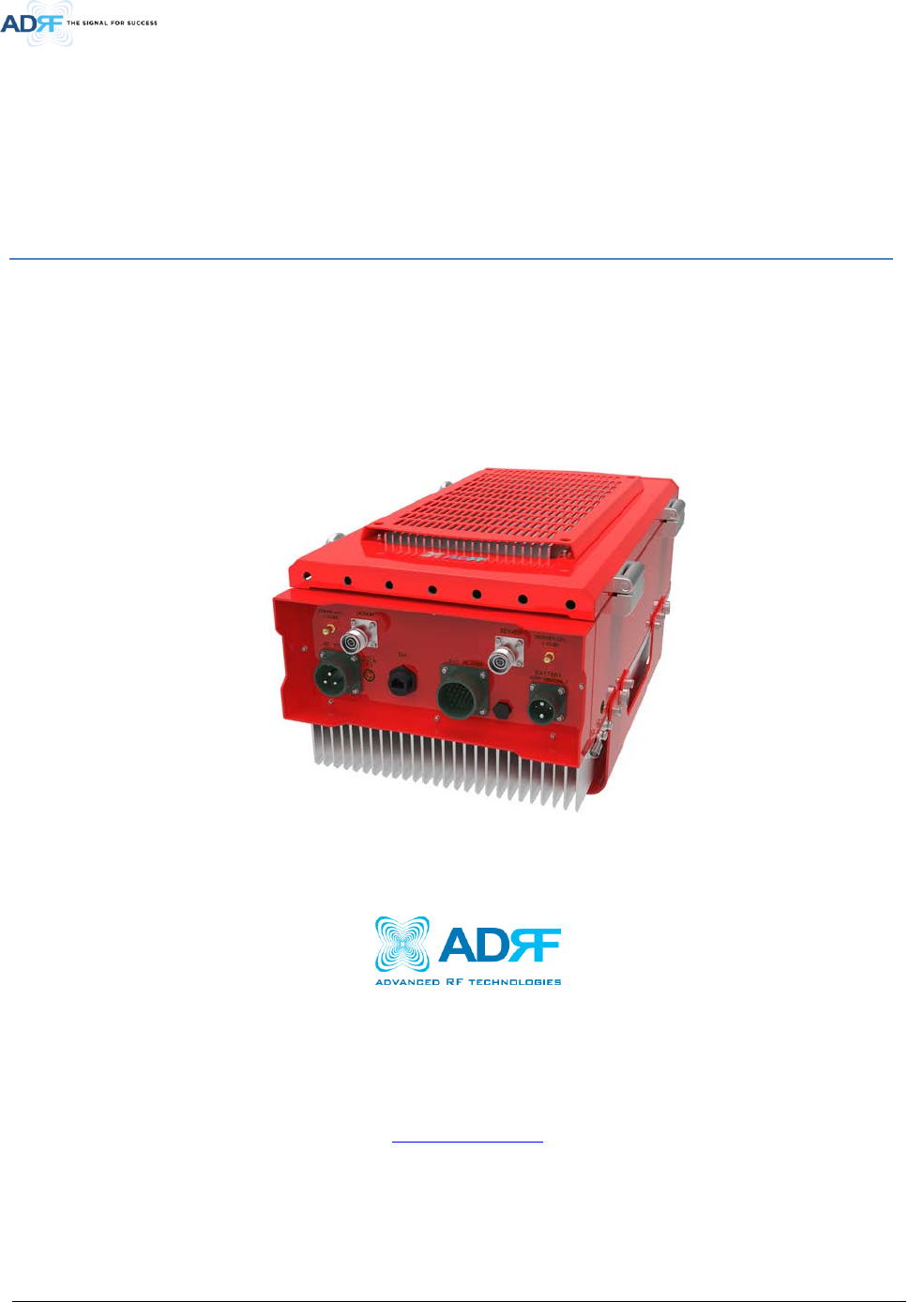
1. INTRODUCTION
PSR-78-9533 bi-directional amplifier (BDA) extends the coverage area of radio communications in buildings and RF
shadow environments. The unit features low noise figure and wide dynamic range.
1.1 Highlights
• Supports both 700MHz and 800MHz Public Safety Frequencies in a single repeater
• Supports a total of 2 wide band and up to 32 non-contiguous narrow band channels (700MHz + 800MHz
PS)
• Air convection cooling without fans
• Sharp Filter Roll-off performance (Wide: 60dBc @ Filter Bandwidth Edge + 1MHz | Narrow: 55dBc @
Filter Bandwidth Edge + 3 * Filter BW)
• Supports SNMP v1, v2c, v3 (get, set, & traps)
• Web-based GUI Interface; No 3rd party GUI software required
• Web-GUI connectivity via DHCP in host mode
• External Alarm Function supporting dry contacts, 11 outputs and 1 input
Advanced RF Technologies, Inc.
10
1.2 Parts List
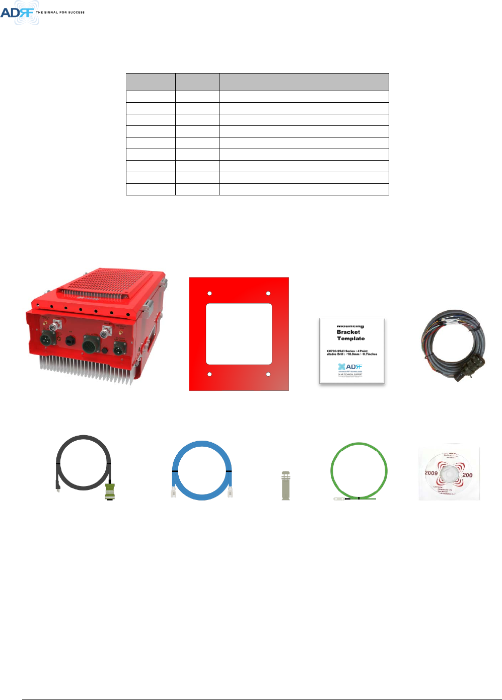
Table 1-1 Parts List
Label Quantity Description
A
1
PSR-78-9533
B
1
Wall Mount Bracket
C
1
Mounting Bracket Template
D
1
AAI Alarm Cable
E
1
AC Power Cable
F
1
Ethernet Cable (Crossover)
G
6
Anchor Bolt
H
1
Ground Cable
I
1
Documentation CD
A B C D
E F G H I
Figure 1-1 PSR-78-9533 Repeater Parts List
Advanced RF Technologies, Inc.
11
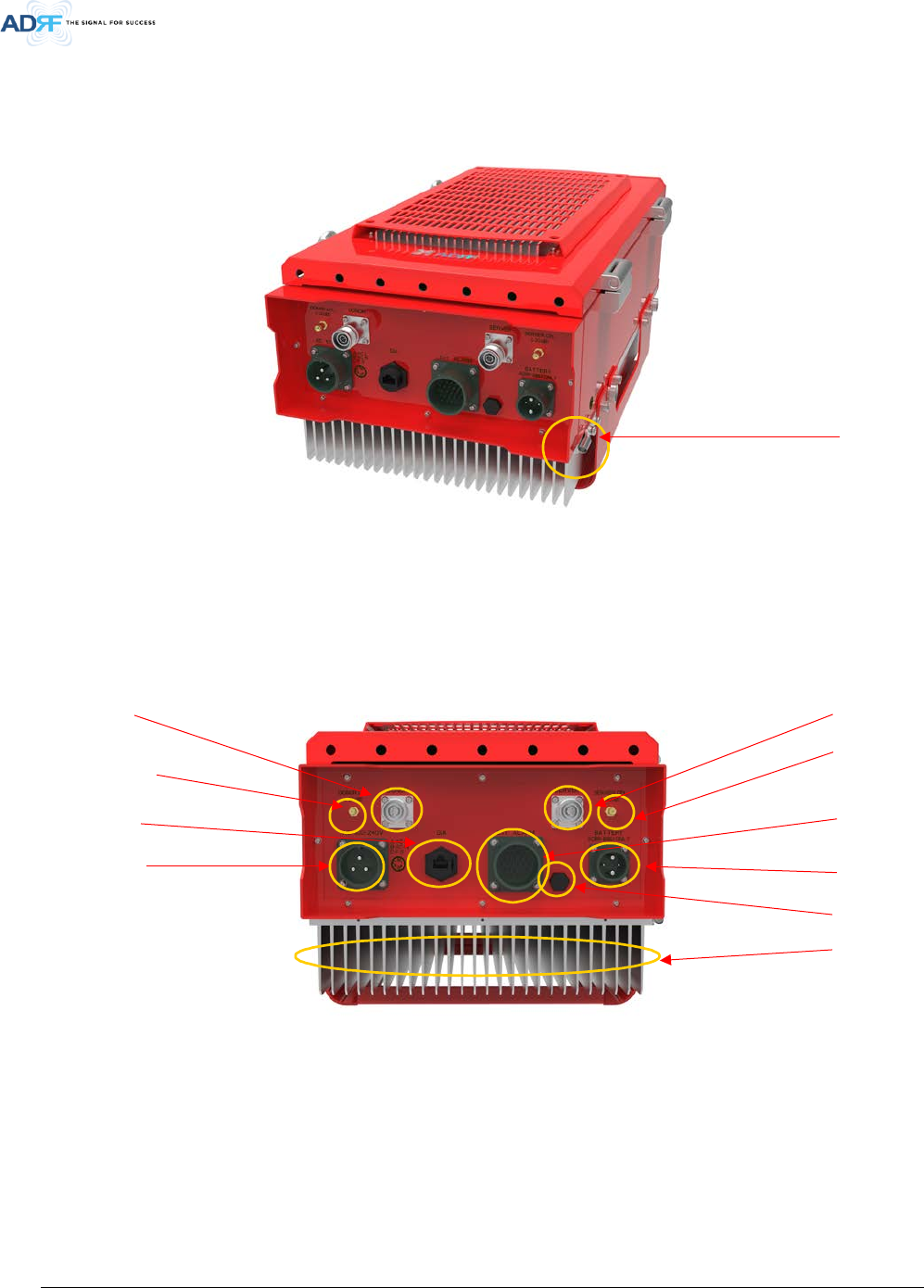
1.3 Quick View
Figure 1-2 PSR-78-9533 Quick View (Bottom)
AAI Alarm Port
ADRF-BBU
B
attery Port
Donor Port
(4.3
-10 Female)
AC Input Port
Ground Terminal
Server Port
(4.3-10 Female)
Sever CPL (DL Output
Monitor Port,
-30dB)
Donor CPL (UL Output
Monitor Port,
-30dB)
Ethernet Port
(RJ
-45)
Heat Sink
Air Vent Hole
Advanced RF Technologies, Inc.
12
1.4 Warnings and Hazards
Opening the PSR-78-9533 could result in electric shock and may cause
severe injury.
Working with the repeater while in operation, may expose the technician to
RF electromagnetic fields that exceed FCC rules for human exposure. Visit the
FCC website at www.fcc.gov/oet/rfsafety to learn more about the effects of
exposure to RF electromagnetic fields.
WARNING! EXPOSURE TO RF
Operating the PSR-78-9533 with antennas in very close proximity facing
each other could lead to severe damage to the repeater.
WARNING! DAMAGE TO REPEATER
Actual separation distance is determined upon gain of antenna used.
Please maintain a minimum safe distance of at least 200 cm while operating near the donor and
the server antennas. Also, the donor antenna needs to be mounted outdoors on a permanent
structure.
RF EXPOSURE & ANTENNA PLACEMENT Guidelines
Opening or tampering the PSR-78-9533 will void all warranties.
WARRANTY
WARNING!
ELECTRIC
SHOCK
Advanced RF Technologies, Inc.
13
Lithium Battery: CAUTION. RISK OF EXPLOSION IF BATTERY IS REPLACED BY INCORRECT TYPE.
DISPOSE OF USED BATTERIES ACCORDING TO INSTRUCTIONS.
Ethernet Instructions: This equipment is for indoor use only. All cabling should be limited to inside
the building.
Preclude indications that Home/ personal use are prohibited.
Use of unauthorized antennas, cables, and/or coupling devices not conforming with
ERP/EIRP is prohibited.
FCC RF Radiation Exposure Statement:
This equipment complies with FCC RF radiation exposure limits set forth for an uncontrolled
environment. This equipment should be installed and operated with a minimum distance of
200cm between the radiator and your body. This transmitter must not be co-located or operating
in conjunction with any other antenna or transmitter.
NOTE: This equipment has been tested and found to comply with the limits for a Class A digital
device, pursuant to part 15 of the FCC Rules. These limits are designed to provide reasonable protection
against harmful interference when the equipment is operated in a commercial environment. This
equipment generates, uses, and can radiate radio frequency energy and, if not installed and used in
accordance with the instruction manual, may cause harmful interference to radio communications.
Operation of this equipment in a residential area is likely to cause harmful interference in which case
Regulatory Warning Statement
Advanced RF Technologies, Inc.
14
WARNING. THIS is NOT a CONSUMER device. It is designed for installation by FCC LICENSEES and
QUALIFIED INSTALLERS. You MUST have an FCC LICENSE or express consent of an FCC Licensee to
operate this device. You MUST register Class B signal boosters (as defined in 47 CFR 90.219) online
at www.fcc.gov/signal-boosters/registration. Unauthorized use may result in significant forfeiture
penalties, including penalties in excess of $100,000 for each continuing violation.
FCC Part 90 Class B
Any changes or modifications not expressly approved by the party responsible for compliance could
void the user's authority to operate this equipment.
FCC Part 15.21
Under Industry Canada regulations, this radio transmitter may only operate using an antenna of a type
and maximum (or lesser) gain approved for the transmitter by Industry Canada. To reduce potential
radio interference to other users, the antenna type and its gain should be so chosen that the equivalent
isotropically radiated power (e.i.r.p.) is not more than that necessary for successful communication.
Conformément à la réglementation d’Industrie Canada, le présent émetteur radio peut
fonctionneravec une antenne d’un type et d’un gain maximal (ou inférieur) approuvé pour l’émetteur
par Industrie Canada.
Dans le but de réduire les risques de brouillage radioélectrique à l’intention desautres utilisateurs,
il faut choisir le type d’antenne et son gain de sorte que la puissance isotroperayonnée quivalente
(p.i.r.e.) ne dépassepas l’intensité nécessaire à l’établissement d’une communication satisfaisante.
RSS-GEN, Sec. 7.1.2– (transmitters)
Advanced RF Technologies, Inc.
15
This radio transmitter (identify the device by certification number, or model number if Category II) has
been approved by Industry Canada to operate with the antenna types listed below with the maximum
permissible gain and required antenna impedance for each antenna type indicated. Antenna types not
included in this list, having a gain greater than the maximum gain indicated for that type, are strictly
prohibited for use with this device.
Le présent émetteur radio (identifier le dispositif par son numéro de certification ou son numéro de
modèle s’il fait partie du matériel de catégorie I) a été approuvé par Industrie Canada pour fonctionner
avec les types d’antenne énumérés ci-dessous et ayant un gain admissible maximal et l’impédance
requise pour chaque type d’antenne. Les types d’antenne non inclus dans cette liste,ou dont le gain
est supérieur au gain maximal indiqué, sont strictement interdits pour l’exploitation de l’émetteur.
RSS-GEN, Sec. 7.1.2– (detachable antennas)
This equipment complies with RF radiation exposure limits set forth for an uncontrolled environment.
This equipment should be installed and operated with a minimum distance of 200 cm between the
radiator and your body. This transmitter must not be co-located or operating in conjunction with any
other antenna or transmitter. RF exposure will be addressed at time of installation and the use of
higher gain antennas require larger separation distances.
RF Radiation Exposure
This 3.5dB back off is only required when multiple carriers are present in the pass-band.
Power Reduction Warning Statement
Advanced RF Technologies, Inc.
16
◈LABEL WARNING◈
Antennas must be installed in accordance with FCC 90.635. With 17 dBi gain antennas the height of
the antenna above average terrain (HAAT) must not exceed 80 m. For different gain antennas refer
to the relevant rules.
Part 90.635 requirement
Advanced RF Technologies, Inc.
17
2. OVERVIEW
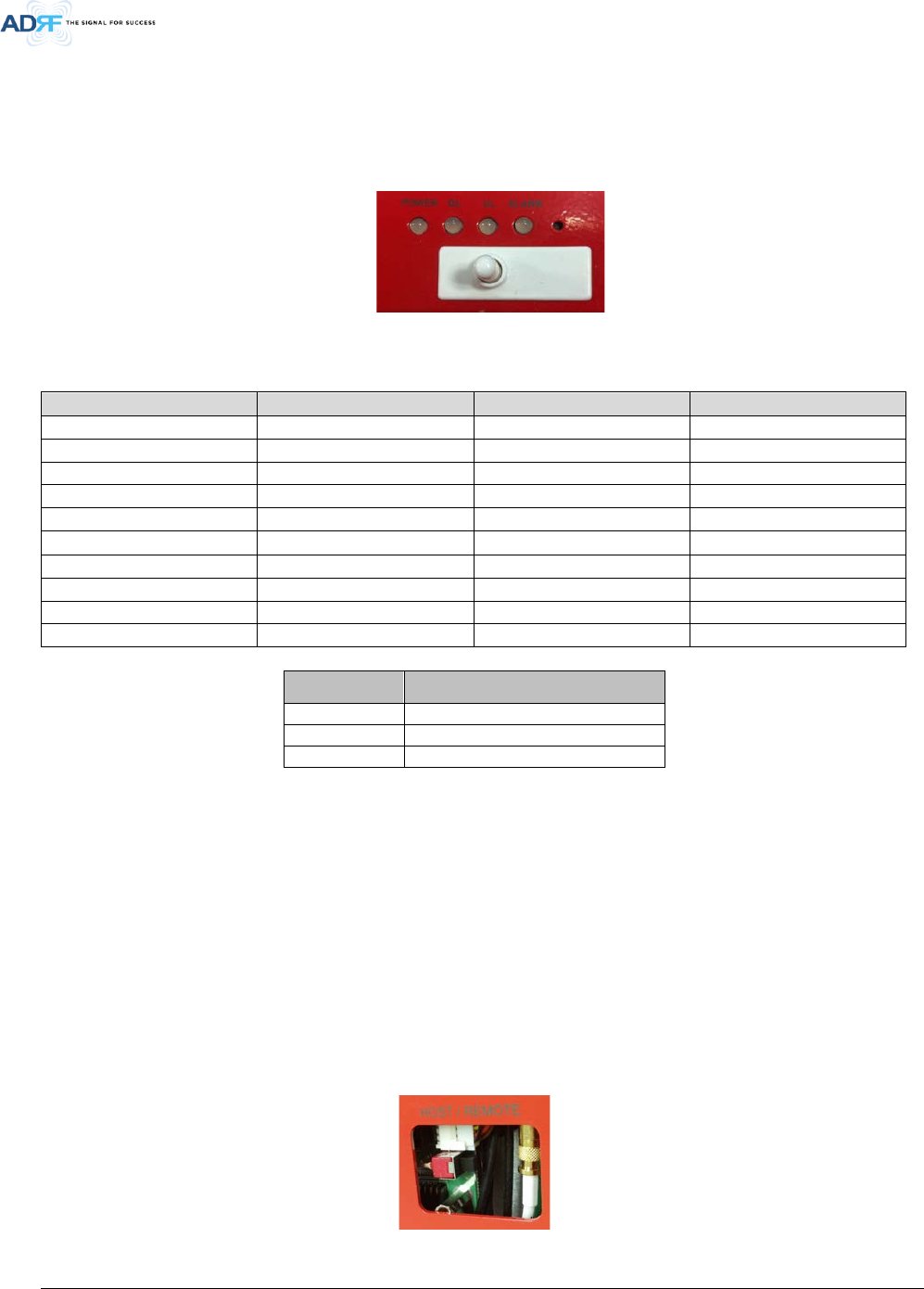
2.1 LED
PSR-78-9533 LED indicator lights are located on the inside of the repeater towards the bottom. Below the LED
indicators is a button that is used to trigger the door open alarm.
Figure 2-1 LED Panel
Table 2-1 LED Specifications
POWER
DL
UL
ALARM
AC Fail
DL Signal Not Detected
UL Out-Band Overload
Power Related Alarms
DC Fail
DL Signal Low Detected
UL Input Overload
RF DL Path Related Alarms
Battery Fail
DL RF Power
UL DSP Over Input
RF UL Path Related Alarms
Low Battery
DL Out-Band Overload
UL Over Input
Over Temperature
Battery Not Charge
DL Input Overload
UL Over Power
DSP Communication
Battery Not Connected
DL DSP Over Input
UL Return Power
Door Open
Over Current
DL Over Input
UL PLL Fail
System Halt
DL Over Power
DL Return Power
DL PLL Fail
LED Indicator Specifications
Solid Green
Normal operation
Solid Yellow
Soft Fail alarm exists in the system
Solid Red
Hard Fail alarm exists in the system
2.2 Host / Remote Switch
The Host/Remote Switch allows the user to switch the default Repeater IP, Subnet Mask, and Gateway of the
Ethernet port of the repeater to an alternative setup. These settings can only be adjusted by logging into the
repeater under HOST mode and configuring the settings under the Modem Box Setting section on the Install
Page (section 5.4.6).
Once the settings are set, flipping the switch to the REMOTE position will reboot the repeater with the new
alternate settings. Please note that when the repeater is set to the REMOTE position, DHCP is disabled and the
repeater will not automatically assign an IP address to any device that connects directly to the repeater.
Host IP: 192.168.63.1 (Fixed IP, unable to modify this IP address)
Remote IP: 192.168.63.5 (Default IP, but can be modified in Host mode)
Figure 2-2 Host/Remote Switch
Advanced RF Technologies, Inc.
18
2.3 Cable Connection
2.3.1 AC Power
AC power is accepted through a standard 3-wire male plug (MS3106A-22-2S) with phase, neutral, and ground
leads. The AC power is wired to a high-efficiency DC switching power supply which is UL approved.
The AC port is located at the bottom of the repeater and has a free range input of 100-240V AC.
Figure 2-3 AC Input Port
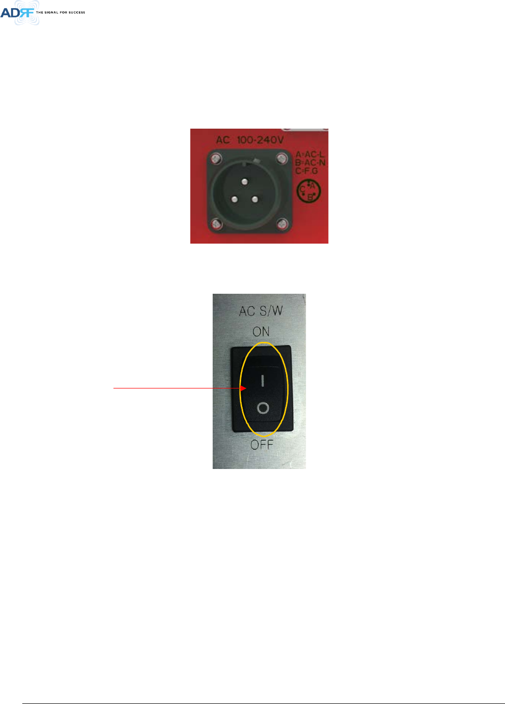
Figure 2-4 AC On/Off Switch
The AC Power on/off switch is on the left-hand side of the PSU which is located inside of the repeater.
AC On/Off switch
Advanced RF Technologies, Inc.
19
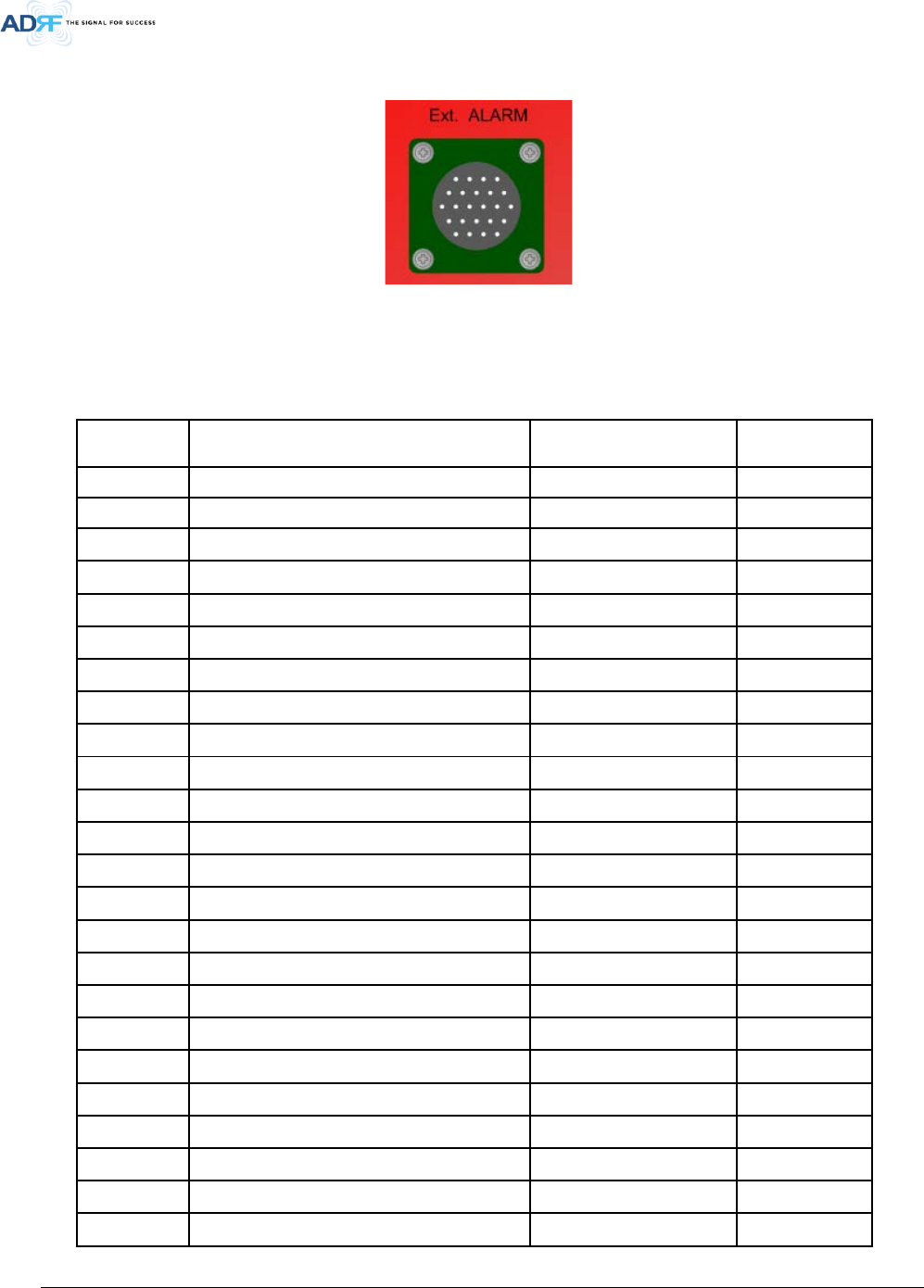
2.3.2 External Alarm
Figure 2-5 External Alarm port
This port should be connected only to the fire alarm control panel.
Table 2-2 External Alarm Port Pin Description
Pin Pin Description (24 pins)
ADRF External Alarm
Box Pin description
Alarm Type
A Donor antenna malfunction_P 1-POS
Output
B Donor antenna malfunction_N 1-NEG Output
C Active RF device malfunction_P 2-POS Output
D Active RF device malfunction_N 2-NEG
Output
E Low battery capacity (70%)_P 3-POS
Output
F Low battery capacity (70%)_N 3-NEG
Output
G System component malfunction_P 4-POS
Output
H System component malfunction_N 4-NEG
Output
J Normal AC Power_P 5-POS
Output
K Normal AC Power_N 5-NEG
Output
L Loss of normal AC Power_P 6-POS
Output
M Loss of normal AC Power_N 6-NEG
Output
N Battery charger failure_P 7-POS
Output
P Battery charger failure_N 7-NEG
Output
G Low battery capacity (70%)_P 8-POS
Output
R Low battery capacity (70%)_N 8-NEG
Output
S Donor antenna malfunction_P 9-POS
Output
T Donor antenna malfunction_N 9-NEG
Output
U Active RF emitting device malfunction_P 10-POS
Output
V Active RF emitting device malfunction_N 10-NEG
Output
W System component malfunction_P 11-POS
Output
X System component malfunction_N 11-NEG
Output
Y Alarm Input-1 - Input
Z GND -
GND

Advanced RF Technologies, Inc.
20
2.3.3 RF
Figure 2-6 RF ports
The RF connections are made via two 4.3-10 female connectors. The RF connector labeled “DONOR” must be
connected to the antenna pointing towards the base station. The DONOR port can receive both 700 and 800MHz
public safety signals. The RF connection labeled “SERVER” must be connected to the antenna facing the area to
be covered by the BDA. The repeater has a single SERVER port that supports both 700 and 800MHz public safety
signals.
The RF connections must be made using cables with an impedance of 50 ohms.
The separation between the antennas is necessary to prevent oscillation. Oscillation occurs when the signal
entering the system continually re-enters, due to the lack of separation between the donor and server antennas.
In other words, the signal is being fed back into the system. This creates a constant amplification of the same
signal. As a result, the noise level rises above the signal level.
To prevent feedback, the donor and server antennas must be separated by an appropriate distance to provide
sufficient isolation. Isolation is attained by separating antennas a sufficient distance so that the output of one
antenna does not reach the input of the other. This distance is dependent on the gain of the repeater.
DONOR – 4.3-10 female which is used to connect the donor antenna (700MHz + 800MHz PS)
DONOR_CPL (30dB) – SMA female 30 dB coupling port which is used to monitor the amplified UL signal
SERVER_CPL (30dB) – SMA female 30 dB coupling port which is used to monitor the amplified DL signal
SERVER – 4.3-10 female which is used to connect the server antenna (700MHz + 800MHz PS)
Advanced RF Technologies, Inc.
21
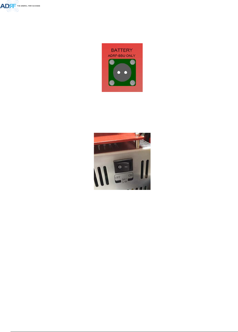
2.3.4 Back Up Battery Port
This port connects to the ADRF-BBS/BBL-24 (24V battery backup unit) via a dedicated cable provided by the
ADRF.
Figure 2-7 Battery Backup Port
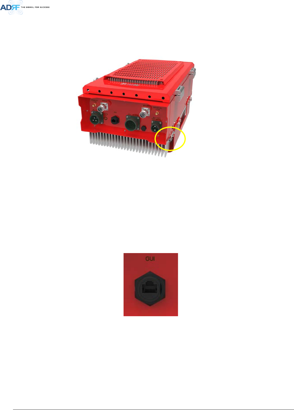
If an ADRF-BBS/BBL-24 is connected to the repeater, the battery switch on the PSU must be switched to the ON
position. This will enable the repeater to charge the ADRF-BBS/BBL-24 battery backup unit when AC power is
present.
Figure 2-8 Battery Switch
The PSR-78-9533 can be connected to an ADRF-BBS/BBL-24 to provide power during a power failure. If an ADRF-
BBS/BBL-24 is utilized, connect it to the PSR-78-9533 via the external battery port.
(WARNING: The circuit breaker switch on the ADRF-BBS/BBL-24 must be set to OFF before connecting it to
the PSR-78-9533 to prevent damage to the repeater or the ADRF-BBS/BBL-24 and personal injury.)
Note: Please contact ADRF Technical Support for assistance if you are unfamiliar with the installation procedure
of the battery box.
Advanced RF Technologies, Inc.
22
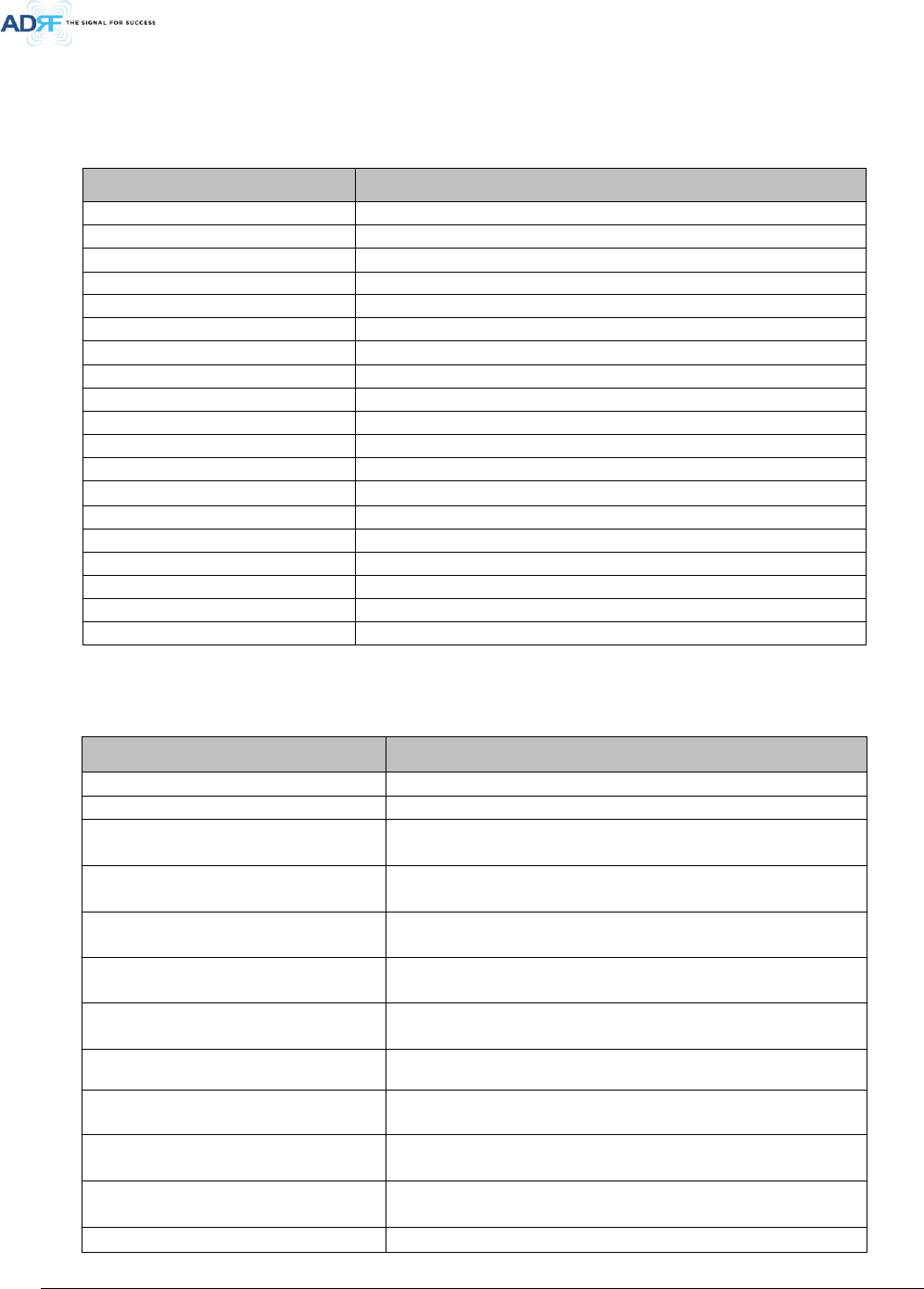
2.3.5 Grounding
A ground cable is included in the box. The grounding terminal is located at the lower right-hand side of the BDA.
The grounding cable should be properly connected before powering on the equipment.
Figure 2-9 Ground Cable Terminal
Ground terminals located on the side of the repeater and can support a ground cable up to 1.25mm² (16AWG)
in diameter and should be permanently connected to a grounding bar.
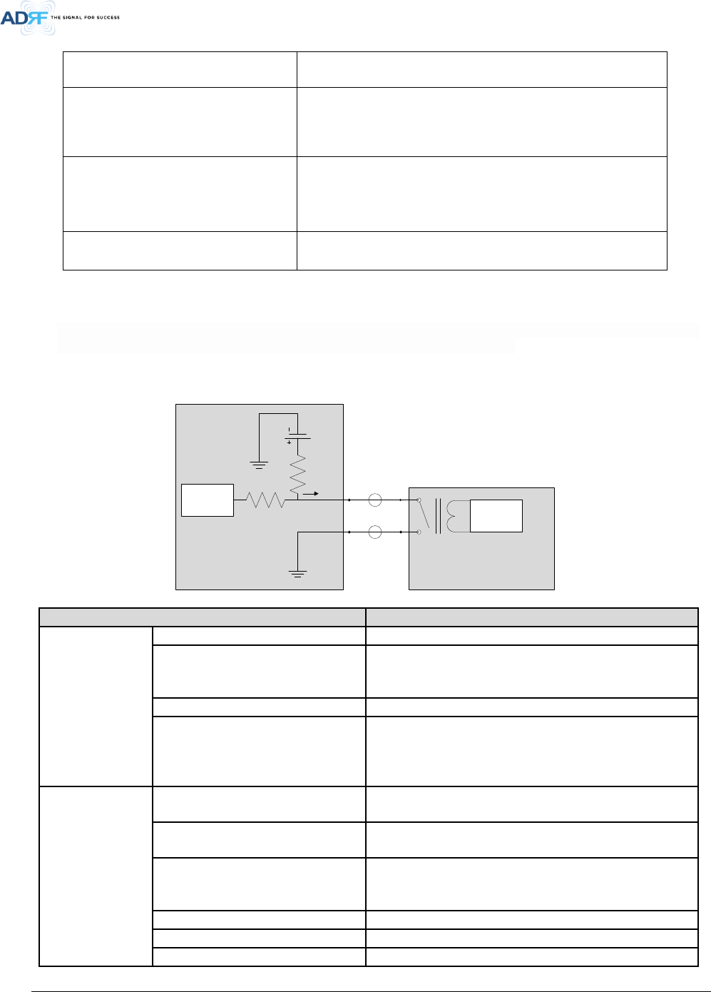
2.3.6 Ethernet Port
The GUI port can be used to communicate directly with the PSR-78-9533 using an RJ-45 crossover cable. The
weatherproof cap must first be unscrewed to gain access to the GUI port.
Figure 2-10 Ethernet Port
Advanced RF Technologies, Inc.
23
3. ALARMS
3.1 Message Board Alarms and Notifications
Table 3-1 Message Board Alarms and Notifications
Parameters
Remark
AC Fail
AC Input is outside of operating range
DC Fail
DC Output is outside of operating range
Temperature
Module is above/below the normal operating temperature
Current
PSU is providing more than the max current
System Halt
System is in a shutdown state due to a hard fail alarm
DSP Fault
System has detected an issue with the internal DSP
OSC
Oscillation detected
DL Signal not detected
DL signal is below the specified level
DL Signal Low
DL signal is below the specified level
Input Overload
Incoming in-band DL or UL signal is too strong
Out of band Overload
Incoming out-band DL or UL signal is too strong
Synthesizer Lock Fail
Issue with internal PLL
DL RF Power
Input + gain does not match the output level (above delta of 6 dB)
Overpower
Output level is above the max output levels
VSWR
Power is being reflected back to the repeater
Heartbeat
Heartbeat is sent out to the NOC
Reboot
Soft reboot performed
Factory setting
Factory default settings restored
Door
Door alarm set/clear
3.2 Alarms
Table 3-2 Alarms
Parameters Remark
AC Fail
Power supply is not operating within specs. (4 seconds)
DC Fail
Power supply is not operating within specs. (4 seconds)
Temperature
Module is above the normal operating temperature. (4 seconds)
Over Temperature [Soft: 80~87 C, Hard: Above 87 C]
Current
Power supply is not operating within specs. (4 seconds)
Over Current [Hard: Above 20A]
System Halt System is in a shutdown state due to a hard fail alarm. (10 cycles)
DSP Fault
System has detected an issue with the internal DSP chip. (Cannot
communicate with DSP)
OSC Oscillation detected.
DL Signal not Detected DL signal is below the specified level. (default: -90dBm, 4 seconds)
DL Signal Low DL signal is below the specified level. (default: -85dBm, 4 seconds)
Input Overload
Input signal is above the threshold. (4 seconds)
(Soft: DL -5dBm/UL -5dBm, Hard: DL +5dBm/UL +5dBm)
Out of Band Overload
Out of band signal is above the threshold. (4 seconds)
(Soft: DL -5dBm/UL -5dBm, Hard: DL +5dBm/UL +5dBm)
Synthesizer Lock Fail
Issue with internal PLL. (4 seconds)
Advanced RF Technologies, Inc.
24
DL RF Power
Input + gain does not match the output level.
(default delta of 6 dB)
Overpower
Output level is above the max output levels.
AGC On case (Soft: AGC Level + 1~2dB, Hard: AGC Level + >2dB)
AGC Off case (Soft: max output level + 1~2dB, Hard: max output
level + >2dB)
VSWR
Power is being reflected back to the repeater. Threshold = output
power - 8dB. For example, if the repeater is outputting 24dBm and
detects 16dBm of return power, then the VSWR will be triggered.
(Alarm will only trigger when output power is 15dBm or greater)
Door Door alarm set: Door open
Door alarm clear: Door close
3.3 External Alarms
The PSR-78-9533 supports dry contact alarms and can be connected to a fire alarm control panel. The user can program the
repeater to either create an open or closed circuit when an alarm is present in the system.
3.3.1 External Alarm Output interface
Simplex Alarm Box
Simplex
Digital Board
24V dc
ADRF PSR Repeater
ADRF
Digital Board
External Alarm Name
Set Condition
Fire Alarm
Donor Antenna Malfunction
- UL Return Power Hard Fail or No DL Signal Detected
Active RF Device Malfunction
- DL Return Power Hard Fail
- DL/UL Over Power Hard Fail
- DL/UL Input Overload Hard Fail
Low Battery Capacity (70% depleted)
- Low Battery Soft Fail
System Component Malfunction
- Over Current Hard Fail
- Over Temperature Hard Fail
- DSP Hard Fail
- Out-band Overload Hard Fail
System Monitoring
Normal AC Power
- AC Normal Set
- AC Fail Soft Clear
Loss of Normal AC Power
- AC Fail Soft Set
- AC Normal Clear
Battery Charger Failure
- Battery Fail Soft Fail
- Battery Not Connected Soft fail
- Battery Not Charge Soft Fail
Low Battery Capacity (70% depleted)
- Low Battery Soft Fail
Donor Antenna Malfunction
- UL Return Power Hard Fail
Active RF Emitting Device Malfunction
- RF Power Soft Fail
Advanced RF Technologies, Inc.
25
External Alarm Name
Set Condition
- DL Return Power Hard Fail
- DL/UL Over Power Hard Fail
- DL/UL Input Overload Hard Fail
System Component Malfunction
- Over Current Hard Fail
- Over Temperature Hard Fail
- DSP Hard Fail
- Out-band Overload Hard Fail
3.3.2 External Alarm Input interface
User Alarm Input Port
No
External Alarm In
User Alarm
Remark
1
ALARM IN 1
TBD
Advanced RF Technologies, Inc.
26
4. INSTALLATION
4.1 Installation Procedures
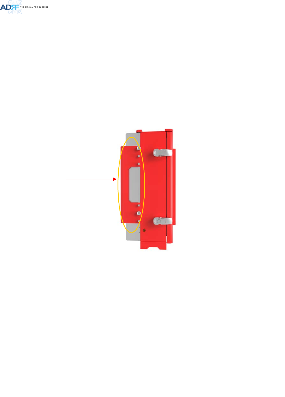
4.1.1 Wall Mount Procedure
• Verify that the PSR-78-9533 and mounting hole are in good condition
• Place the PSR-78-9533 mounting bracket template up against the wall and mark off mount holes
• Drill the appropriate size holes and install the included wall anchors
• Remove the wall mount bracket from the repeater and bolt the wall mount bracket to the wall
• Place the repeater onto the wall mount bracket and secure the bracket to the repeater
• Connect the GND cable
• Connect the Antenna cable
• Connect the Power cable
Figure 4-1 Wall Mount
Wall Mount
Bracket
Advanced RF Technologies, Inc.
27
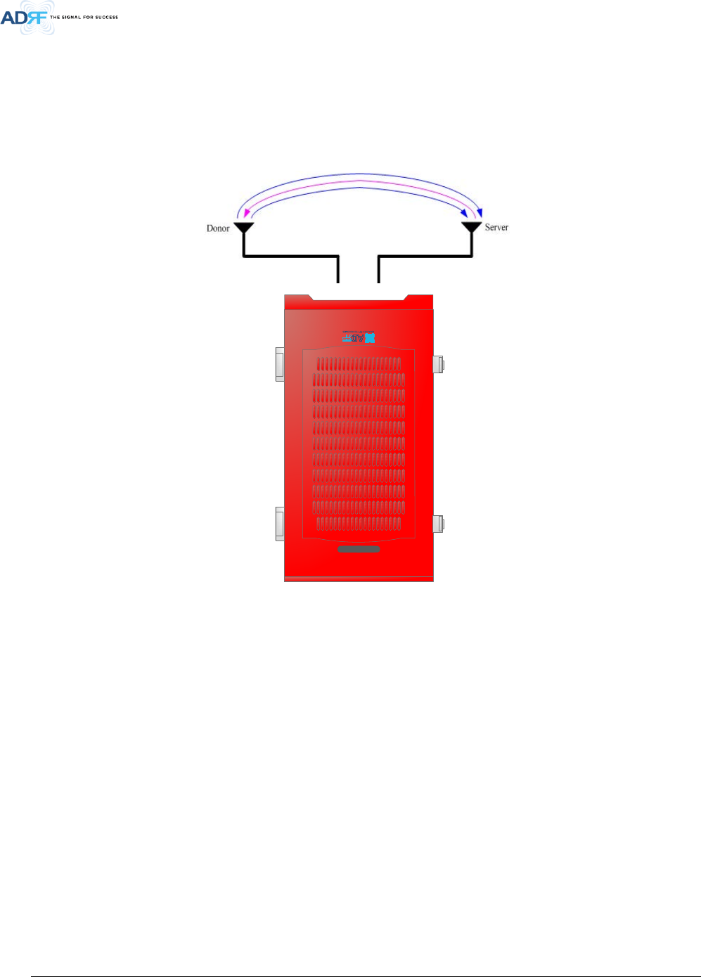
4.2 Antenna Separation/Isolation
The separation between the donor and server antennas is necessary to prevent oscillation. Oscillation occurs
when the signal entering the system continually re-enters, due to the lack of separation between the donor and
server antennas. In other words, the signal is being fed back into the system. This creates a constant
amplification of the same signal. As a result, the noise level rises above the signal level.
Figure 4-2 RF Repeater Oscillation
To prevent feedback, the donor and server antennas must be separated by an appropriate distance to provide
sufficient isolation. Isolation can be attained by separating antennas at a sufficient distance so that the output
of one antenna does not reach the input of the other. This distance is dependent on the gain of the repeater.
Recommended isolation value is 15dB greater than the user-set gain of the repeater. For example, if the user-
set gain of the repeater is 50dB, then an isolation of 65dB or greater is required. In the same manner, to utilize
the maximum gain of 95dB of the PSR-78-9533, an isolation of at least 110dB is required.
PSR-78-9533

Advanced RF Technologies, Inc.
28
DO NOT APPLY A.C. POWER TO THE BDA UNTIL CABLES ARE CONNECTED TO BOTH PORTS OF
THE BDA AND THE ANTENNAS.
1. To mount on a wall. Using appropriate screws and anchors and attach the BDA to the wall at the four
mounting holes.
2. Ensure that the isolation between the donor antenna and the serving antennas is at least 15 dB greater
than the BDA gain.
3. Connect the cable from the donor antenna to the BDA connector labeled “DONOR” and the cable from the
serving antennas to the BDA connector labeled “SERVER”.
4. Connect the AC power cord to the BDA and turn on the switch at the left of PSU.
5. Installation of the BDA is now complete. Adjust the gain controls to suit the specific signal environment
through the GUI on your PC.
- To prevent feedback, the donor and server antennas must be separated by an appropriate distance to
provide sufficient isolation. Isolation is attained by separating antennas a sufficient distance so that the
output of one antenna does not reach the input of the other. This distance is dependent on the gain of the
repeater.
- Prior to equipment use, the device must be registered with the FCC. This can be done through the FCC’s
website at https://signalboosters.fcc.gov/signal-boosters
Advanced RF Technologies, Inc.
29
5. PSR-78-9533 WEB-GUI SETUP
The Web-GUI allows the user to communicate with the repeater either locally or remotely. To connect to the
repeater locally, you will need a laptop with an Ethernet port and an RJ-45 crossover cable. To connect to the
repeater remotely, you will need to have an active internet connection via an external modem or LAN.
5.1 Repeater/PC Connection Using Web-GUI
Verify that your Local Area Network Connection is set to obtain an IP address automatically under the Internet
Protocol (TCP/IP) properties.
- If you are connecting to the unit remotely (use of a modem), then skip step above.
Connect the RJ-45 crossover cable between the laptop’s Ethernet port and the repeater’s Ethernet port.
Launch an Internet Browser.
Type the following IP address into the address bar of the Internet Browser: http://192.168.63.1
- If you are connecting to the unit remotely, then type the IP address of the modem to connect to the unit
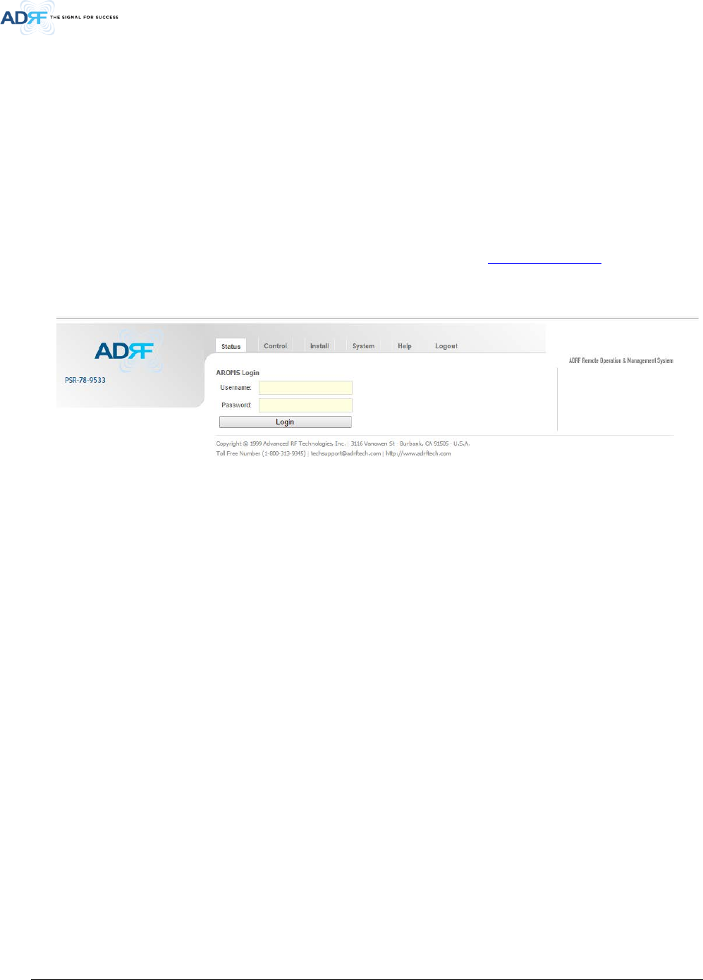
The following login screen will appear:
Figure 5-1 Login Page
If you are not the Administrator, please type in your assigned username & password which you should have
received from the Administrator.
The default username and password for the General User is adrf & adrf, respectively.
The default Administrator login is admin & admin, respectively.
Advanced RF Technologies, Inc.
30
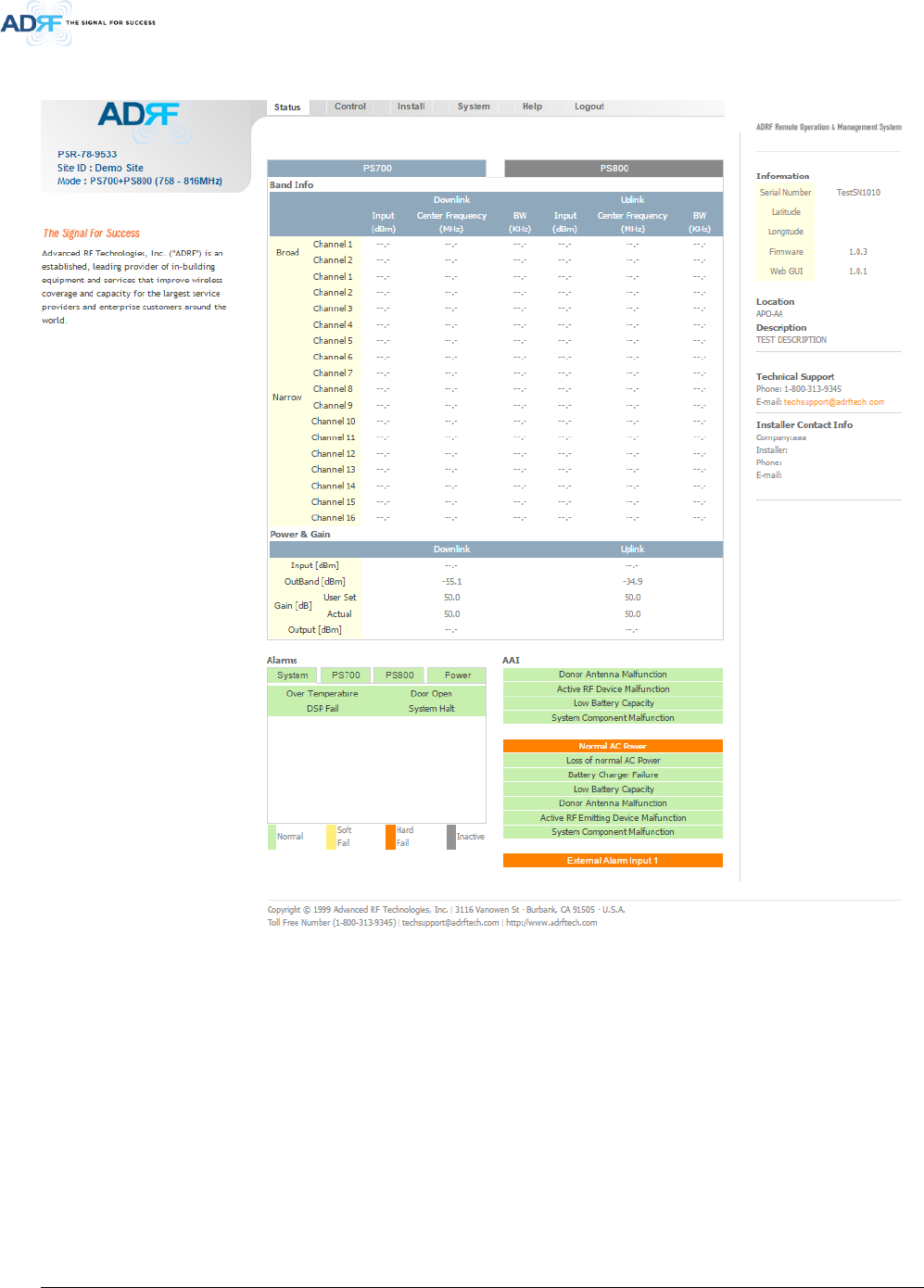
5.2 Status Tab
Figure 5-2 Status Tab
Advanced RF Technologies, Inc.
31
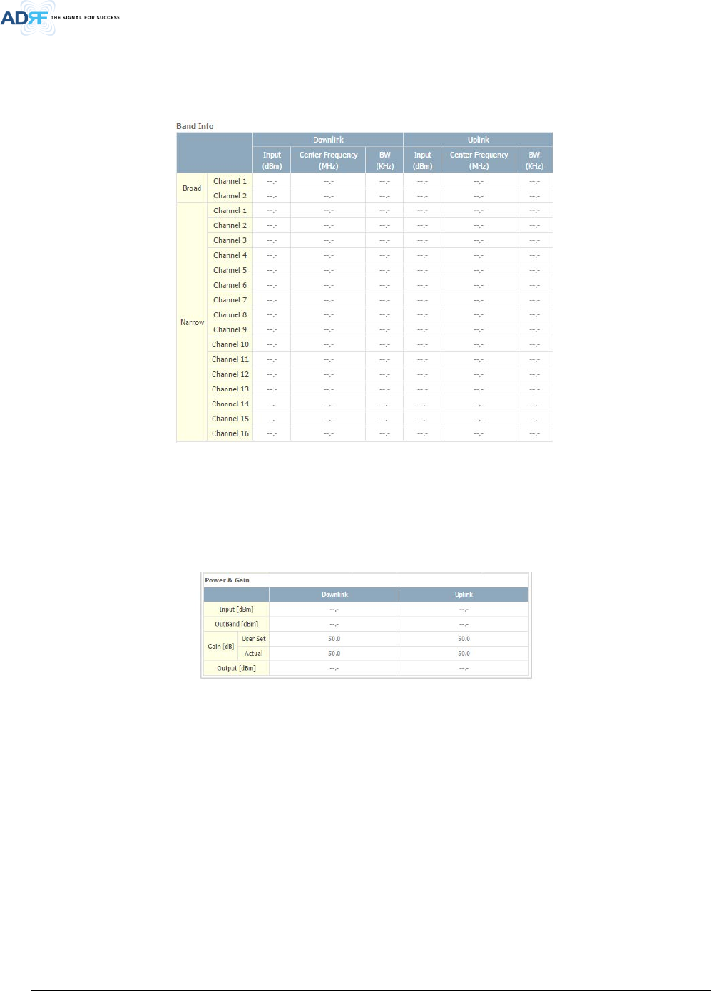
5.2.1 Band Info
The Band Info section displays frequency information along with the corresponding bandwidths that have been
set from the Install tab. Input levels for each channel are also displayed in this section.
Figure 5-3 Band Info Display
5.2.2 Power & Gain
This section displays the Input, Gain, and Output for both downlink and uplink.
Figure 5-4 Power & Gain Display
Input [dBm] – Displays the in-band Downlink/Uplink signal level. The system will display “--.-“ when the input
level is < -90 dBm.
Outband [dBm] – Displays the out-band composite power.
Gain [dB]
- User Set: Displays the amount of gain that the user set.
- Actual: Displays the actual amount of gain that is currently in use.
Output [dB] – Displays the Downlink/Uplink composite output power levels. The system will display “--.-“, when
the output level is < +5 dBm.
Advanced RF Technologies, Inc.
32
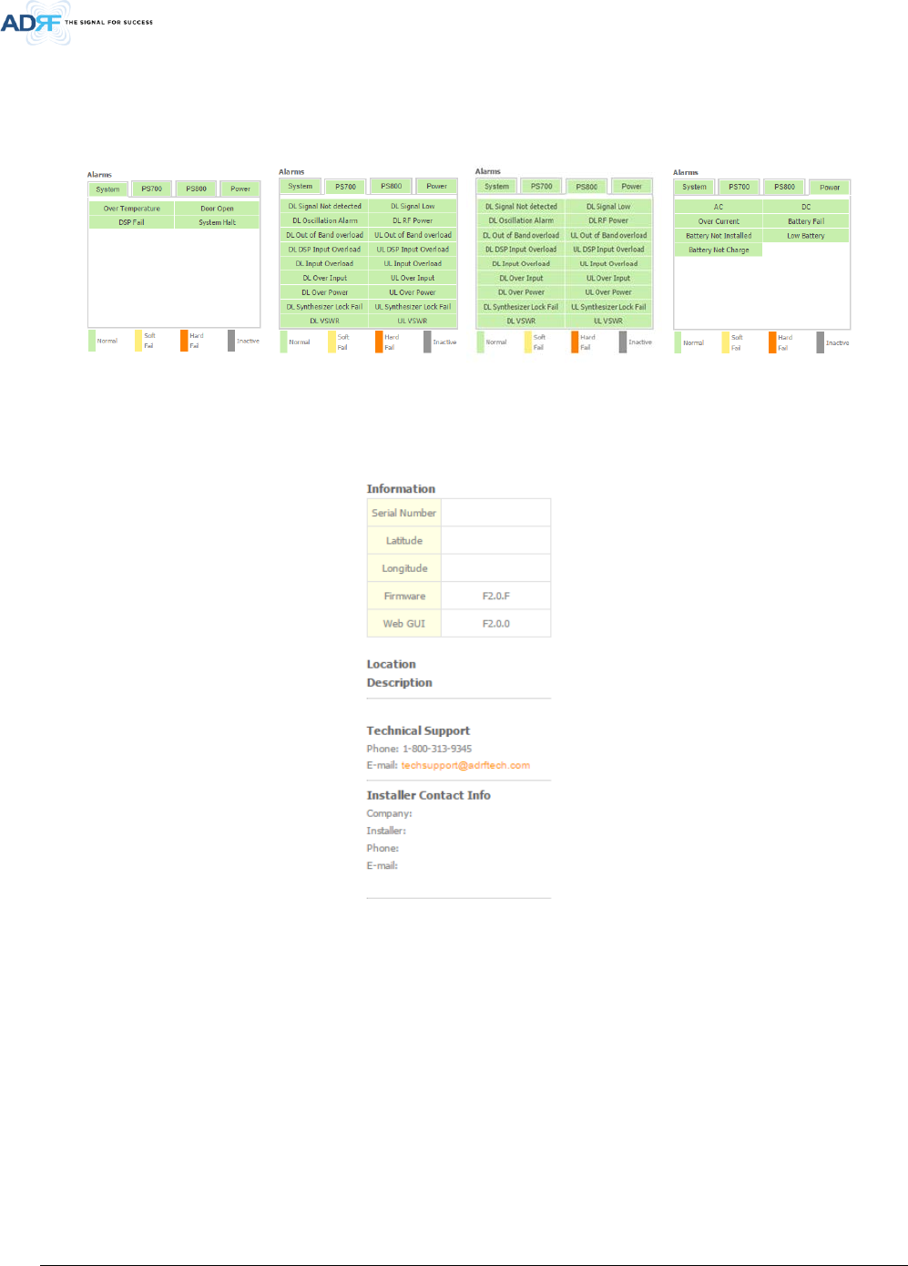
5.2.3 Alarms
This section displays the alarm status for System alarms, RF Alarms, and Power alarms. If an alarm is present in
the system, then the color of the alarm tab will change according to the type of failure.
Figure 5-5 Alarm Display
5.2.4 Repeater Info / Repeater Location / Technical Support / Installer Contact Info
Figure 5-6 Repeater Info / Repeater Location / Technical Support / Installer Contact Info
Repeater Info: Displays the serial number, latitude, longitude, firmware version, and Web-GUI version
Repeater Location: Displays the address where the repeater is installed
Technical Support: Displays ADRF’s Technical Support contact information
Installer Contact Info: Displays the installer’s name, phone, and e-mail address
Note: Once successfully logged in, the repeater model name and the site/cascade ID will be displayed on
the top of all the windows (except for the Main Window).
Advanced RF Technologies, Inc.
33
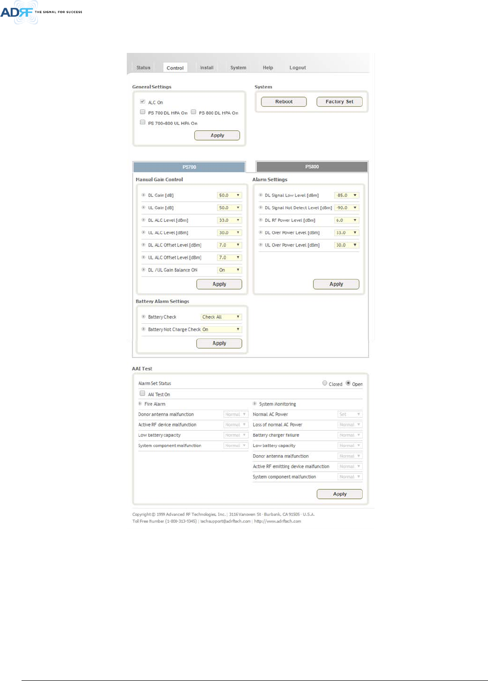
5.3 Control Tab
Figure 5-7 Control page
Advanced RF Technologies, Inc.
34
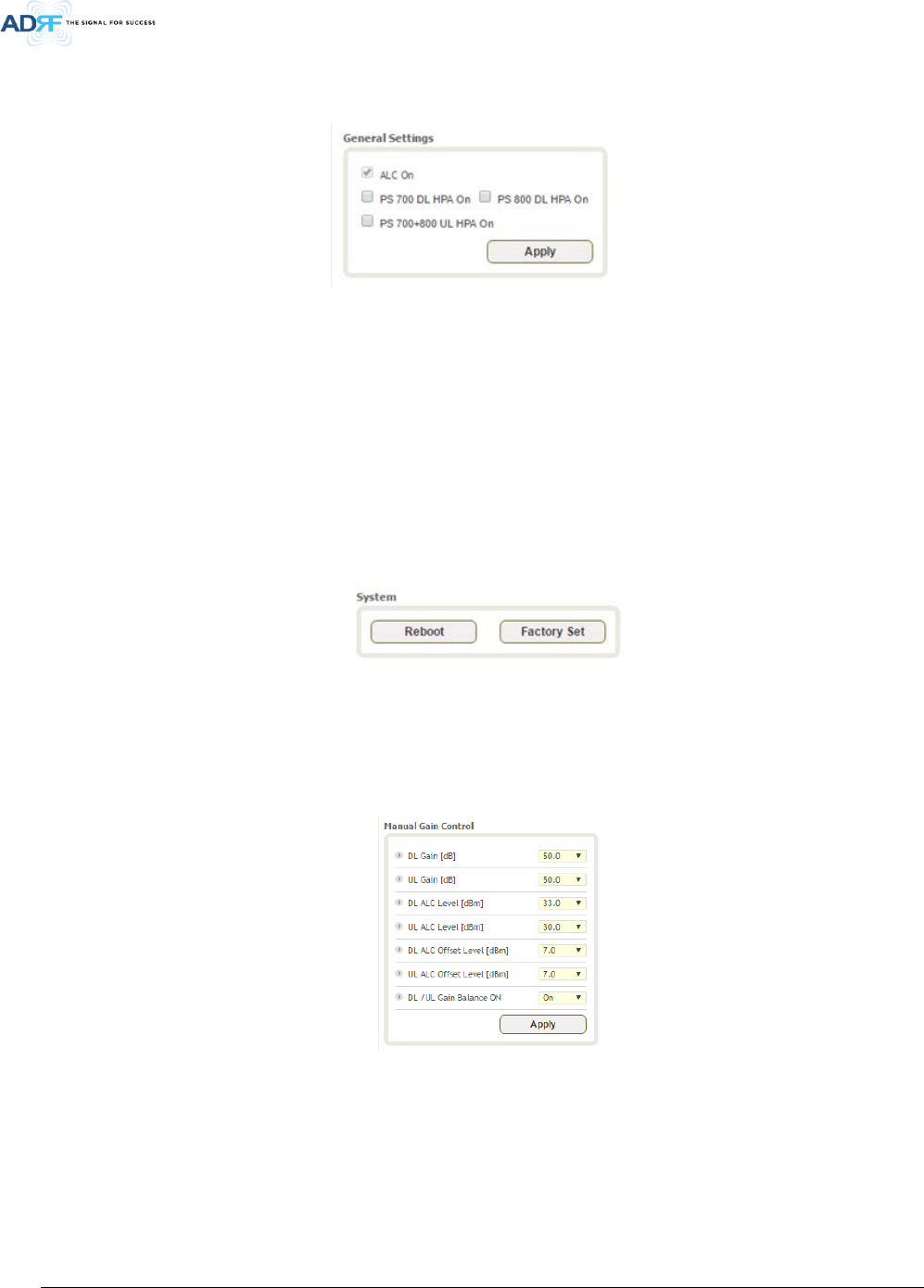
5.3.1 General Setting
The General Setting section allows the user to enable/disable amplifiers and the ALC routine.
Figure 5-8 General Setting
ALC ON: Enables or disables Automatic Level Control (ALC)
PSR 700 DL HPA On: Enables or disables the Downlink High Power Amplifier (HPA) for 700MHz PS
PSR 800 DL HPA On: Enables or disables the Downlink High Power Amplifier (HPA) for 800MHz PS
PSR 700+800 UL HPA On: Enables or disables the Uplink High Power Amplifier (HPA) for 700+800MHz PS
To enable/disable any of the settings, click on the checkbox and click the Apply button.
5.3.2 System
Under the System section, the user is able to perform soft reboot on the repeater and also can restore factory
default settings.
Figure 5-9 System
Reboot: Performs a soft reboot of the repeater
Factory Set: Restores all settings to factory defaults
5.3.3 Manual Gain Control
Figure 5-10 Manual Gain Control Setting
DL/UL Gain: Gain levels of the repeater can be specified here
DL/UL ALC Level: Prevents the output power from exceeding the specified value
DL/UL Output ALC Offset: If any ALC attenuation has been applied, the system will release this attenuation
when the signal level drops by the specified level
DL /UL Gain Balance ON: Allows the user to enable or disable the gain balance. When gain balance is enabled,
the delta value between the downlink and uplink gains remain constant

Advanced RF Technologies, Inc.
35
5.3.4 Alarm Settings
Figure 5-11 Alarm Settings
DL Signal Low Level: Allows the user to specify how low the signal can be before triggering a “Downlink Signal
Low” soft-fail alarm
DL Signal Not Detected Level: Allows the user to specify how low the signal can be before triggering a “Downlink
Signal Not Detected” soft-fail alarm
DL RF Power Level: Allows the user to set a maximum deviation value for the downlink RF power before
triggering a “DL RF Power Level” soft-fail alarm
- For example, if the input signal is -50 dBm and the gain is set to 60 dB, the expected output power should
be 10 dBm. If the Downlink RF Power alarm value is set to 6dB, then a soft-fail alarm will trigger if the
output power falls below 4 dBm
DL Over Power Level: DL Over Power Alarm will trigger when the DL output level exceeds this level
UL Over Power Level: UL Over Power Alarm will trigger when the UL output level exceeds this level
Battery Check:
• Check All – All battery related alarms are checked which include Battery Fail, Battery Not Installed, Low
Battery, and Battery Not Charge
• Except Install – Only Battery Fail, Low Battery, and Battery Not Charge alarms are checked
• Check Off – Does not perform any battery check
Battery Not Charge Check:
• On – Checks for the Battery Not Charge alarm
• Off – Disables the check for the Battery Not Charge alarm
Advanced RF Technologies, Inc.
36
5.4 Install Tab
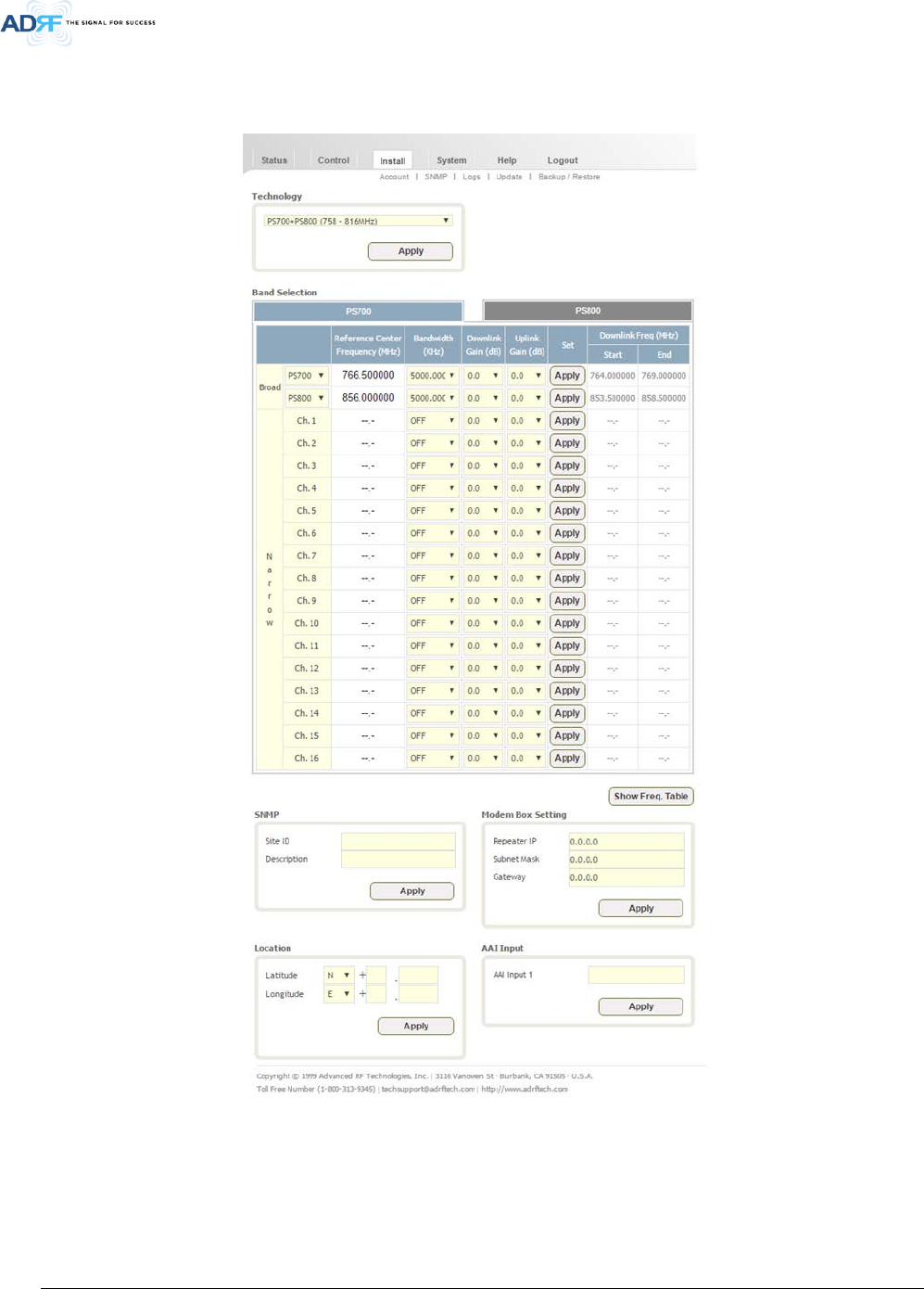
5.4.1 Install
Figure 5-12 Install Page
Advanced RF Technologies, Inc.
37
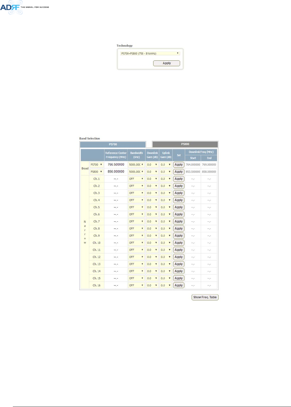
5.4.2 Technology
This section allows the user to set the repeater mode to either use PS700, PS800, or PS700+PS800.
Figure 5-13 Technology
The following choices are available from the dropdown:
• PS700 (758-775MHz)
• PS800 (851-861MHz)
• PS700+PS800 (758-861MHz)
5.4.3 Band Selection
Figure 5-14 Band Selection
Band selection allows the user specify the desired frequncies by inputting the center frequencies and selecting
the bandwidths.
Reference Center Frequency: The user can input the center frequency of the pass-band.
Bandwidth: Allows the user to select the desired bandwidth for the passband. Choices for wide band
frequencies include 5 and 10MHz. Narrow band choices include 6.25, 12.5, 25.0, and 200 KHz.
Downlink/Uplink Gain: Minor gain adjustments can be performed on a per channel basis to equalize signal
levels
Downlink Freq - Start: Displays the start frequency of the pass-band once the band selection has been set
Downlink Freq - End: Displays the end frequency of the pass-band once the band selection has been set
Advanced RF Technologies, Inc.
38
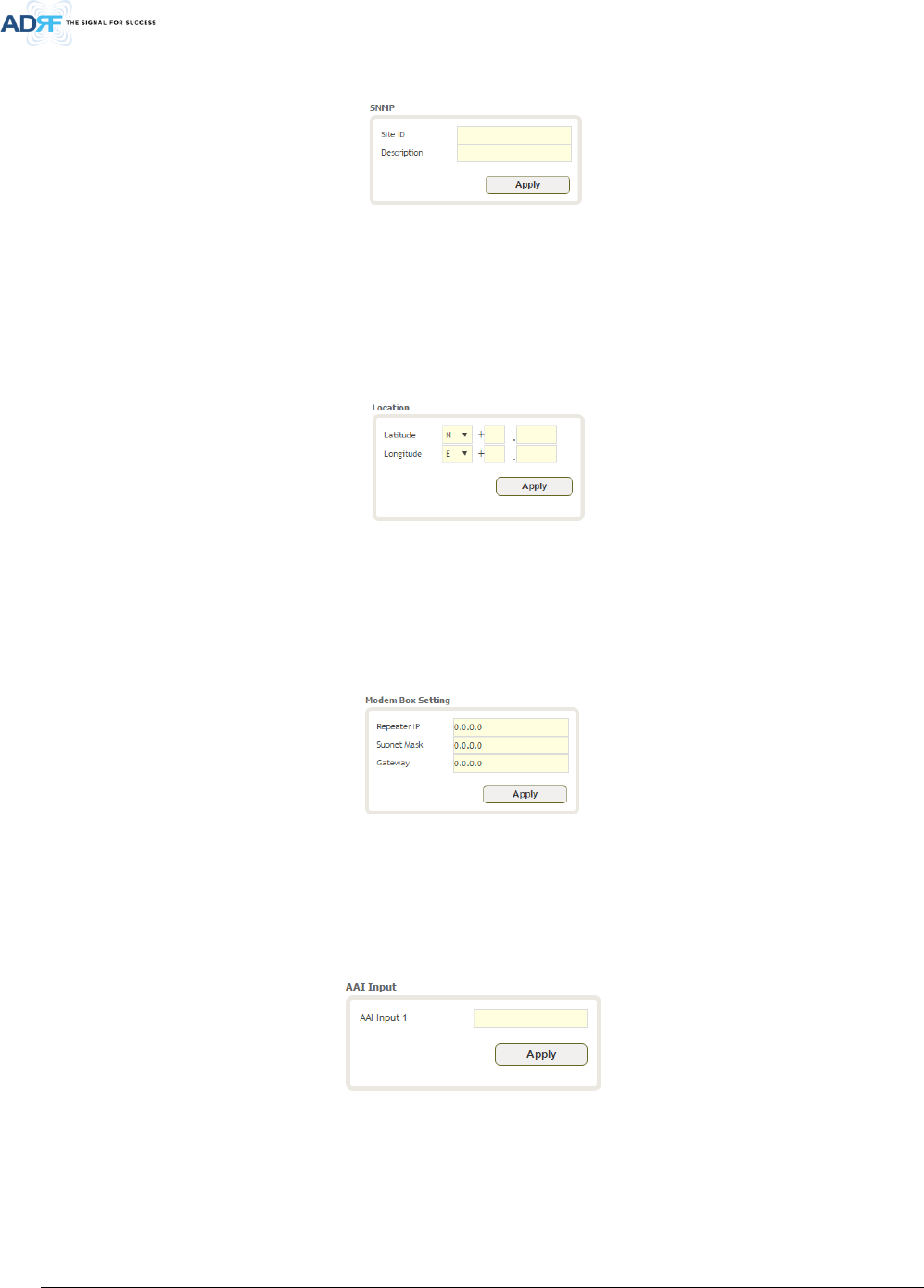
5.4.4 SNMP
Figure 5-15 SNMP
The SNMP section allows you to specify the Site ID and Description. The Site-ID is the code that is used to
identify the repeater.
5.4.5 Location
This section allows the user to input the latitude and the longitude of the repeater.
Figure 5-16 Location Setting
5.4.6 Modem Box Setting
This section allows the user to specify alternative Repeater IP, Subnet Mask, and Gateway settings. These
settings are enabled when the Host/Remote switch is set to the Remote position.
Figure 5-17 Modem Box Setting
5.4.7 AAI Input
The PSR-VU-9537 can accept a dry contact input alarms. The alarm can be labeled in this section. Once the
alarm is labeled, it will show up in the system with the new custom names on the Status tab.
Figure 5-18 AAI Input
Advanced RF Technologies, Inc.
39
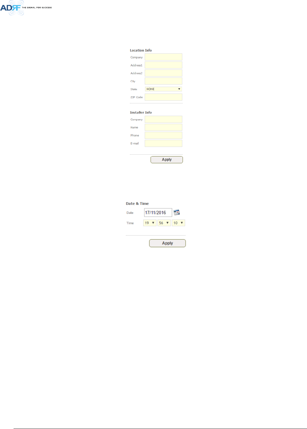
5.4.8 Location Info / Installer Info
This section allows the user to specify the address of the repeater and also the information of the installer.
Figure 5-19 Repeater Location Info / Repeater Installer Info
5.4.9 Date & Time
This section allows the user to specify the current date and time.
Figure 5-20 Date & Time Setting
Advanced RF Technologies, Inc.
40
5.5 System
The System tab allows the user to perform firmware updates, upload closeout packages, view any changes to
the system, backup existing configuration, and add/remove user accounts, and change the login credentials of
the Administrator.
5.5.1 System: Account
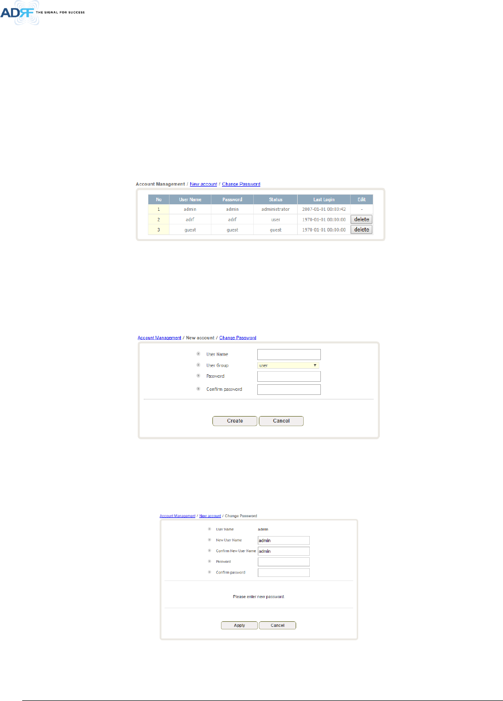
5.5.1.1 System: Account – Account Management
The Account Management section allows the Administrator to delete any user accounts. Please note that the
Account Management section is only available if you are logged into the system as the Administrator. To delete
a user account click on the Account Management link and under the Delete column, click on the delete button.
Figure 5-21 System: Account- Account Management
5.5.1.2 System: Account – New Account
The New account section allows the Administrator to create a new user account. Please note that the New
account section is only available if you are logged into the system as the Administrator. To create a new user
account click on the new account link and fill in the fields shown.
Figure 5-22 System: Account- New Account
5.5.1.3 System: Account – Change Password
The Change Password section allows the current user who is logged into the system to change their login
credentials.
Figure 5-23 System: Account- Change Password
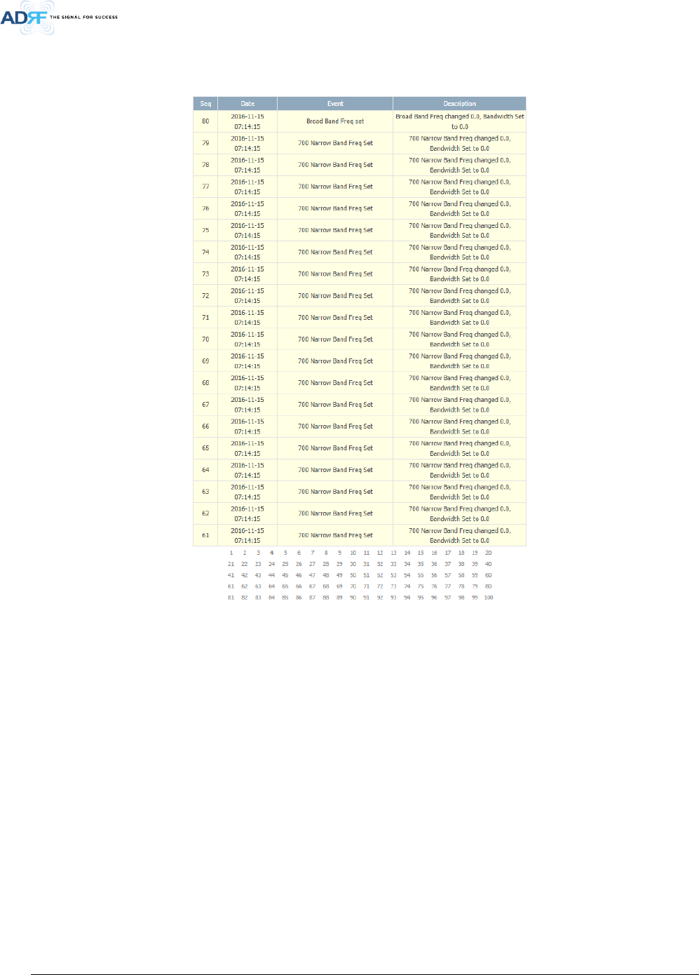
5.5.2 System – User Log
Advanced RF Technologies, Inc.
41
This section displays system events that have taken place. The User Log displays who has made the changes,
the time and date of when the event took place, and what changes were made to the system.
Figure 5-24 System – User Log
Advanced RF Technologies, Inc.
42
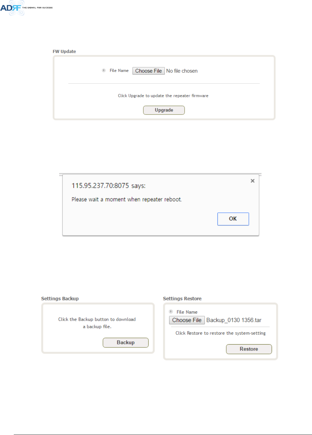
5.5.3 System – Update
To perform a firmware update, click on the Update tab and the following screen will appear.
Figure 5-25 System – Update
Click on the Choose File button and locate the firmware file.
Click on the Upgrade button to perform the firmware update.
Once the firmware update is complete, the following popup message will appear:
Figure 5-26 Pop-up Message after System Update is Complete
5.5.4 System – Backup & Restore
The backup section allows the user to save the settings of the repeater. To perform the backup, click on the
Backup button and you will be prompted to save the backup file. To restore the settings to the system, click on
Choose File button, select the backup file, and click the Restore button.
Figure 5-27 System Backup

Advanced RF Technologies, Inc.
43
5.6 Help
If an internet connection is available, clicking on the Help Tab will redirect the user to our Technical Support
page.
Figure 5-28 Help
5.7 Logout
Clicking the Logout button will log the current user off the system.
6. MAINTENANCE GUIDE FOR PSR-78-9533 REPEATER
6.1 Periodic Inspection Checklist
Check for loose connections between the repeater and antennas. If connections are loose, make sure that all
connections are tightly fastened properly.
Cables and connectors are in good condition.
Ensure that the repeater brackets are in good condition and that the repeater is securely fastened.
6.2 Preventive Measures for Optimal Operation
6.2.1 Recommendations
Perform the Periodic Inspection Checklist quarterly or semi-annually.
6.2.2 Precautions
Do not operate the repeater with the antennas in extremely close proximity to one another as this may cause
damage to the repeater.
Do not change the parameters unless instructed to do so by an authorized supervisor.
Do not move the repeater unless instructed to do so by an authorized supervisor.
Do not detach any cables to the repeater unless repair of respective components is necessary.

Advanced RF Technologies, Inc.
44
7. WARRANTY AND REPAIR POLICY
7.1 General Warranty
The PSR-78-9533 carries a Standard Warranty period of two (2) years unless indicated otherwise on the package
or in the acknowledgment of the purchase order.
7.2 Limitations of Warranty
Your exclusive remedy for any defective product is limited to the repair or replacement of the defective product.
Advanced RF Technologies, Inc. may elect which remedy or combination of remedies to provide in its sole
discretion. Advanced RF Technologies, Inc. shall have a reasonable time after determining that a defective
product exists to repair or replace the problem unit. Advanced RF Technologies, Inc. warranty applies to repaired
or replaced products for the balance of the applicable period of the original warranty or ninety days from the
date of shipment of a repaired or replaced product, whichever is longer.
7.3 Limitation of Damages
The liability for any defective product shall in no event exceed the purchase price for the defective product.
7.4 No Consequential Damages
Advanced RF Technologies, Inc. has no liability for general, consequential, incidental or special damages.
7.5 Additional Limitation on Warranty
Advanced RF Technologies, Inc. standard warranty does not cover products which have been received
improperly packaged, altered, or physically damaged. For example, broken warranty seal, labels exhibiting
tampering, physically abused enclosure, broken pins on connectors, any modifications made without Advanced
RF Technologies, Inc. authorization, will void all warranty.
7.6 Return Material Authorization (RMA)
No product may be returned directly to Advanced RF Technologies, Inc. without first getting an approval from
Advanced RF Technologies, Inc. If it is determined that the product may be defective, you will be given an RMA
number and instructions on how to return the product. An unauthorized return, i.e., one for which an RMA
number has not been issued, will be returned to you at your expense. Authorized returns are to be shipped to
the address on the RMA in an approved shipping container. You will be given our courier information. It is
suggested that the original box and packaging materials should be kept if an occasion arises where a defective
product needs to be shipped back to Advanced RF Technologies, Inc. To request an RMA, please call (800) 313-
9345 or send an email to techsupport@adrftech.com.

Advanced RF Technologies, Inc.
45
8. SPECIFICATIONS
8.1 Electrical Specifications
Table 8-1 Electrical Specifications
Parameters
Specifications
Remarks
DL UL
Frequency Range
(MHz)
FirstNet + PS 700
758 ~ 768 MHz (for FCC) 788 ~ 798 MHz (for FCC) LTE (5 MHz)
769 - 775MHz(For FCC)
(768-769MHzGuard band)
768 – 775 MHz (For ISED)
799 - 805 MHz(For FCC)
(798- 799MHz Guard band)
798 - 805 MHz (For ISED)
APCO 25
PS 800 851 - 861 806 - 816 APCO 25
Composite Output
Power
FirstNet / PS 700 /
FirstNet + PS 700
33 dBm 30 dBm
PS 800 33 dBm 30 dBm
FirstNet + PS 700 +
PS 800
36 dBm
(33dBm + 33dBm)
30 dBm
System Gain (dB) 95 95
Filter selection Broad / Narrow / Broad + Narrow band
Simultaneous Filter
Support numbers
Broad Band
2 (non-contiguous) @ FirstNet / PS 700 / PS 800 / FirstNet
+ PS 700 / FirstNet + PS 700 + PS 800
Narrow Band
Up to 16 (Non-contiguous) @ PS 700 / PS 800
Up to 32 (Non-contiguous) @ PS 700 + PS 800
Filter Bandwidth
Broad (MHz) 5, 10MHz
Extra filter upload available by
custom request.
Narrow (KHz) 75 ~331.25 (6.25 x n , n= 12~53)
Filter Roll-off Broad (MHz) 60dBc@Filter Bandwidth Edge + 1MHz
Narrow (KHz)
55dBc @Filter Bandwidth Edge + 3 * Filter BW
Spurious FCC Rule Compliant
Passband Ripple ±2 dB
ALC Dynamic Range ≥ 60dB
Gain Dynamic Range ≥ 45dB
Channel Setting Resolution 0.025 kHz
Noise Figure @ Max. gain ≤5dB
System
Group Delay
Broad Band <6us
Narrow Band
<126us@6.25KHz BW, <67us@12.5KHz BW, <36us@25KHz
BW, <10us@200KHz BW
Power Supply 100 -240 VAC, 60 Hz (Free Voltage) Optional battery backup
Power Consumption <150 W
Max RF Input Power without over drive -20dBm
No damage Max Input Power +10 dBm
Impedance 50 Ω
VSWR <1.3 : 1
Dry Contacts NFPA 1221 2016 Code Compliant
Remote Alarming /
Network Management
Dry Contacts, Web-GUI, SNMP, SNMP-Traps (External
Wireless Modem Required)
Advanced RF Technologies, Inc.
46
Humidity 5% - 90% RH Condensed
Operating at Ambient Temperature -40°F to +140°F (-40°C to +60°C)
8.2 Mechanical Specifications
Table 8-2 Mechanical Specifications
Parameters Specifications Comments
Dimensions W x D x H 11.0 x 9.0 x 21.67 in (w/o mounting bracket)
Weight 55 lbs (w/o mounting bracket)
RF Connector 4.3-10 (Female)
Weather Resistances IP66
8.3 Power Specifications
Table 8-3 Power Specifications
Parameters Specifications Comments
AC Power
100 -240 VAC, 60 Hz (Free Voltage)
AC Supply Protection
Fuse & Circuit Protector
T6.3L250V
Battery Backup
Power Consumption
AC 150W (120V/1.25A), DC 24V/6.25A
Ground
External Threaded Stud
8.4 Warranty & Certificates
Table 8-4 Warranty & Certificates
Parameters Specifications Comments
MTBF
> 100,000 Hours
Ambient
Compliance
UL60950
FCC CFR47 part 15
FCC CFR47 part 90
Warranty 2 Years
Advanced RF Technologies, Inc.
47
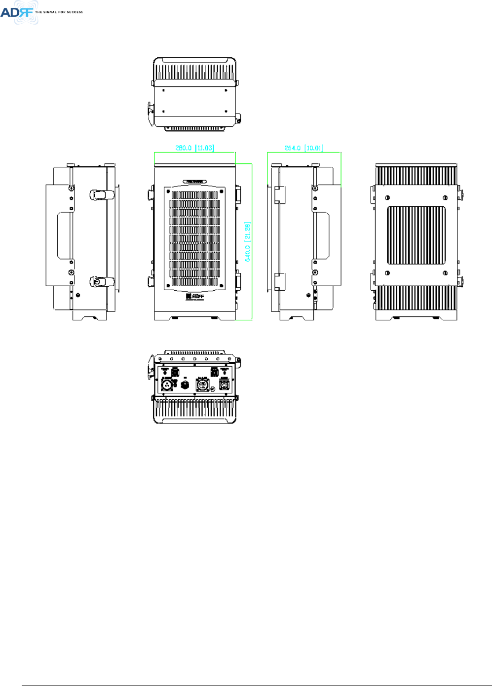
9. MECHANICAL DRAWING
Figure 9-1 PSR-78-9533 Mechanical Drawing

Advanced RF Technologies, Inc.
48
10. APPENDIX
10.1 Shutdown Retry Logic
The function of the built-in shutdown routine is to protect the repeater from any further damage from a hard-
fail that the system may be experiencing.
Within 5 seconds of a hard-fail alarm being detected, the repeater will start the shutdown routine. The repeater
will shut down by powering of the HPAs (high-powered amplifiers) for 30 seconds.
After 30 seconds have elapsed, the repeater will power on the HPAs and check to see if the hard-fail alarm still
exists. If the hard-fail alarm still exists, then the repeater will shut down for 1 minute (double the time of the
previous shutdown time).
After 1 minute has elapsed, the repeater will power on the HPAs and check to see if the hard-fail alarm still
exists. If the hard-fail alarm still exists, then the repeater will shut down for 2 minutes (double the time of the
previous shutdown time).
The shutdown routine will repeat itself a total of 10 times. If the hard-fail alarm still exists after the 10th retry,
then the repeater will turn off its HPAs permanently until a reset is performed or factory set is executed.