Users Manual

NetVanta 150 Series
Hardware Installation Guide
1700412E1 NetVanta 150
61700412E1-34A
July 2006
Trademarks NetVanta 150 Wireless Access Point ABG Hardware Installation Guide
2 Copyright © 2006 ADTRAN, Inc. 61700412E1-34A
Trademarks
Any brand names and product names included in this manual are trademarks, registered trademarks, or
trade names of their respective holders.
To the Holder of the Manual
The contents of this manual are current as of the date of publication. ADTRAN reserves the right to change
the contents without prior notice.
In no event will ADTRAN be liable for any special, incidental, or consequential damages or for
commercial losses even if ADTRAN has been advised thereof as a result of issue of this publication.
Software Licensing Agreement
Each ADTRAN product contains a single license for ADTRAN supplied software. Pursuant to the
Licensing Agreement, you may: (a) use the software on the purchased ADTRAN device only and (b) keep
a copy of the software for backup purposes. This Agreement covers all software installed on the system as
well as any software available on the ADTRAN website. In addition, certain ADTRAN systems may
contain additional conditions for obtaining software upgrades.
901 Explorer Boulevard
P.O. Box 140000
Huntsville, AL 35814-4000
Phone: (256) 963-8000
Copyright © 2006 ADTRAN, Inc.
All Rights Reserved.
Printed in U.S.A.
Changes or modifications to this unit not expressly approved by the party responsible for
compliance could void the user’s authority to operate the equipment.

NetVanta 150 Wireless Access Point ABG Hardware Installation Guide Conventions
61700412E1-34A Copyright © 2006 ADTRAN, Inc. 3
Conventions
Notes provide additional useful information.
Cautions signify information that could prevent service interruption or damage to
equipment.
Warnings provide information that could prevent injury or endangerment to human
life.

Safety Instructions NetVanta 150 Wireless Access Point ABG Hardware Installation Guide
4 Copyright © 2006 ADTRAN, Inc. 61700412E1-34A
Safety Instructions
When using your telephone equipment, please follow these basic safety precautions to reduce the risk of
fire, electrical shock, or personal injury:
1. Do not use this product near water, such as a bathtub, wash bowl, kitchen sink, laundry tub, in a
wet basement, or near a swimming pool.
2. Avoid using a telephone (other than a cordless-type) during an electrical storm. There is a remote
risk of shock from lightning.
3. Do not use the telephone to report a gas leak in the vicinity of the leak.
4. Use only the power cord, power supply, and/or batteries indicated in the manual. Do not dispose of
batteries in a fire. They may explode. Check with local codes for special disposal instructions.
5. The socket-outlet shall be installed near the equipment and shall be easily accessible.
Save These Important Safety Instructions

NetVanta 150 Wireless Access Point ABG Hardware Installation Guide FCC-Required Information
61700412E1-34A Copyright © 2006 ADTRAN, Inc. 5
FCC-Required Information
FCC regulations require that the following information be provided in this manual:
1. This equipment complies with Part 68 of FCC rules and requirements adopted by ACTA. Each
registered interface has a label that contains, among other information, a product identifier in the
format US:AAAEQ##TXXXX. If requested, provide this information to the telephone company.
2. If this equipment causes harm to the telephone network, the telephone company may temporarily
discontinue service. If possible, advance notification is given; otherwise, notification is given as
soon as possible. The telephone company will advise the customer of the right to file a complaint
with the FCC.
3. The telephone company may make changes in its facilities, equipment, operations, or procedures
that could effect the proper operation of this equipment. Advance notification and the opportunity
to maintain uninterrupted service are given.
4. If experiencing difficulty with this equipment, please contact ADTRAN for repair and warranty
information. The telephone company may require this equipment to be disconnected from the
network until the problem is corrected or it is certain the equipment is not malfunctioning.
5. This unit contains no user-serviceable parts.
6. This equipment is designed to connect to the telephone network or premises wiring using an
FCC-compatible modular jack, which is compliant with Part 68 and requirements adopted by
ACTA.

FCC Radio Frequency Interference Statement NetVanta 150 Wireless Access Point ABG Hardware
6 Copyright © 2006 ADTRAN, Inc. 61700412E1-34A
FCC Radio Frequency Interference Statement
This equipment has been tested and found to comply with the limits for a Class B digital device, pursuant
to Part 15 of the FCC Rules. These limits are designed to provide reasonable protection against harmful
interference in a residential installation. This equipment generates, uses, and can radiate radio frequency
energy and, if not installed and used in accordance with the instruction manual, may cause harmful
interference to radio communications. However, there is no guarantee that interference will not occur in a
particular installation. If this equipment does cause harmful interference to radio or television reception,
which can be determined by turning the equipment off and on, the user is encouraged to try to correct the
interference by one or more of the following measures:
• Reorient or relocate the receiving antenna.
• Increase the separation between the equipment and receiver.
• Connect the equipment into an outlet on a circuit different from that to which the receiver is connected.
• Consult the dealer or an experienced radio/TV technician for help.
NetVanta 150 Wireless Access Point ABG Hardware Installation Guide FCC Compliance Notice: Radio
61700412E1-34A Copyright © 2006 ADTRAN, Inc. 7
FCC Compliance Notice: Radio Frequency Notice
This device complies with part 15 of the FCC Rules. Operation is subject to the following two conditions:
1. This device may not cause harmful interference. 2. This device must accept any interference received,
including interference that may cause undesired operation.
Placement and Range Guidelines
The maximum indoor range for 802.11b devices is 500 feet (152.4m). However, the physical placement of
your wireless access point (WAP) can affect the operating range of the unit. When determing the
placement of your WAP, consider the following guidelines to avoid significant performance degradation or
inability to wirelessly connect to the WAP:
• Place the WAP away from potential sources of interference, such as PCs, large metal surfaces,
microwaves, and 2.4 GHz cordless phones.
• Place the WAP in an elevated location such as a high shelf that is near the center of the wireless
coverage area for all mobile devices.
RF Exposure Warning for North America, and Australia
To meet FCC and other national safety guidelines for RF exposure, the antennas for
this device must be installed with a minimum separation distance of 7.9in (20cm)
from any person. The antennas shall not be colocated with other antenna or radio
transmitter.
You are cautioned that changes or modifications not expressly approved by the party responsible for compliance could void your
authority to operate the equipment.
According to FCC 15.407(e), the device is intended to operate in the frequency band of 5.15GHz to 5.25GHz under all conditions
of normal operation. Normal operation of this device is restricted to indoor used only to reduce any potential for harmful interference
to co-channel MSS operations.

Industry Canada Compliance InformationNetVanta 150 Wireless Access Point ABG Hardware Installation
8 Copyright © 2006 ADTRAN, Inc. 61700412E1-34A
Industry Canada Compliance Information
The Industry Canada label applied to the product (identified by the Industry Canada logo or the “IC:” in
front of the certification/registration number) signifies that the Industry Canada technical specifications
were met.
The Ringer Equivalence Number (REN) for this terminal equipment is supplied in the documentation or on
the product labeling/markings. The REN assigned to each terminal device indicates the maximum number
of terminals that can be connected to a telephone interface. The termination on an interface may consist of
any combination of devices subject only to the requirement that the sum of the RENs of all the devices
should not exceed five (5).
Canadian Emissions Requirements
This digital apparatus does not exceed the Class B limits for radio noise emissions from digital apparatus
as set out in the interference-causing equipment standard entitled “Digital Apparatus,” ICES-003 of the
Department of Communications.
Cet appareil numérique respecte les limites de bruits radioelectriques applicables aux appareils numériques
de Class A prescrites dans la norme sur le materiel brouilleur: “Appareils Numériques,” NMB-003 edictee
par le ministre des Communications.

NetVanta 150 Wireless Access Point ABG Hardware Installation Guide Warranty
61700412E1-34A Copyright © 2006 ADTRAN, Inc. 9
Warranty
ADTRAN will repair and return this product within the warranty period if it does not meet its published
specifications or fails while in service. Warranty information can be found in the Support section of the
ADTRAN website at http://www.adtran.com.
Product Registration
Registering your product helps ensure complete customer satisfaction. Please take time to register your
products in the Support section of the ADTRAN website at http://www.adtran.com
Product Support Information
A return material authorization (RMA) is required prior to returning equipment to ADTRAN. For service,
RMA requests, training, or more information, use the contact information shown below.
Repair and Return
If you determine that a repair is needed, please contact our Customer and Product Service (CaPS)
department to have an RMA number issued. CaPS should also be contacted to obtain information
regarding equipment currently in house or possible fees associated with repair.
Identify the RMA number clearly on the package (below the address), and return to the following address:
Pre-Sale Inquiries and Applications Support
Your reseller should serve as the first point of contact for support. If additional pre-sales support is needed,
the ADTRAN Support website provides a variety of support services such as a searchable knowledge base,
the latest product documentation, application briefs, case studies, and a link to submit a question to an
Applications Engineer. All of this, and more, is available in the Support section of the ADTRAN website at
http://www.adtran.com.
When needed, further pre-sales assistance is available by calling our Applications Engineering
Department.
CaPS Department (256) 963-8722
ADTRAN Customer and Product Service
901 Explorer Blvd. (East Tower)
Huntsville, Alabama 35806
RMA # _____________
Applications Engineering (800) 615-1176

Product Support Information NetVanta 150 Wireless Access Point ABG Hardware Installation Guide
10 Copyright © 2006 ADTRAN, Inc. 61700412E1-34A
Post-Sale Support
Your reseller should serve as the first point of contact for support. If additional support is needed, the
ADTRAN website provides a variety of support services such as a searchable knowledge base, updated
firmware releases, latest product documentation, service request ticket generation and trouble-shooting
tools. All of this, and more, is available in the Support section of the ADTRAN website at
http://www.adtran.com.
When needed, further post-sales assistance is available by calling our Technical Support Center. Please
have your unit serial number available when you call.
Installation and Maintenance Support
The ADTRAN Custom Extended Services (ACES) program offers multiple types and levels of installation
and maintenance services which allow you to choose the kind of assistance you need. This support is
available at:
For questions, call the ACES Help Desk.
Training
The Enterprise Network (EN) Technical Training Department offers training on our most popular products.
These courses include overviews on product features and functions while covering applications of
ADTRAN's product lines. ADTRAN provides a variety of training options, including customized training
and courses taught at our facilities or at your site. For more information about training, please contact your
Territory Manager or the Enterprise Training Coordinator.
Technical Support (888) 4ADTRAN
International Technical Support 1-256-963-8716
http://www.adtran.com/aces
ACES Help Desk (888) 874-ACES (2237)
Training Phone (800) 615-1176, ext. 7500
Training Fax (256) 963-6700
Training Email training@adtran.com

61700412E1-34A Copyright © 2006 ADTRAN, Inc. 11
Table of Contents
Introduction to the NetVanta Solution. . . . . . . . . . . . . . . . . . . . . . . . . . . . . . . . . . . . . . . . . . . . . . . . . . 17
Features and Specifications . . . . . . . . . . . . . . . . . . . . . . . . . . . . . . . . . . . . . . . . . . . . . . . . . . . . . . . . 18
Unpack and Inspect the System . . . . . . . . . . . . . . . . . . . . . . . . . . . . . . . . . . . . . . . . . . . . . . . . . . . . 19
Contents of ADTRAN Shipments . . . . . . . . . . . . . . . . . . . . . . . . . . . . . . . . . . . . . . . . . . . . . . . . . 19
Physical Description . . . . . . . . . . . . . . . . . . . . . . . . . . . . . . . . . . . . . . . . . . . . . . . . . . . . . . . . . . . . . . . . 20
Reviewing the Base Unit Front Panel Design . . . . . . . . . . . . . . . . . . . . . . . . . . . . . . . . . . . . . . . . . . . 20
Front Panel LEDs . . . . . . . . . . . . . . . . . . . . . . . . . . . . . . . . . . . . . . . . . . . . . . . . . . . . . . . . . . . . . 20
Reviewing the Rear Panel Design . . . . . . . . . . . . . . . . . . . . . . . . . . . . . . . . . . . . . . . . . . . . . . . . . . . 21
Rear Panel Interfaces. . . . . . . . . . . . . . . . . . . . . . . . . . . . . . . . . . . . . . . . . . . . . . . . . . . . . . . . . . 21
Unit Installation . . . . . . . . . . . . . . . . . . . . . . . . . . . . . . . . . . . . . . . . . . . . . . . . . . . . . . . . . . . . . . . . . . . . 22
Installing the Antennas . . . . . . . . . . . . . . . . . . . . . . . . . . . . . . . . . . . . . . . . . . . . . . . . . . . . . . . . . . . . 22
Mounting Options . . . . . . . . . . . . . . . . . . . . . . . . . . . . . . . . . . . . . . . . . . . . . . . . . . . . . . . . . . . . . . . . 22
Wall Mounting. . . . . . . . . . . . . . . . . . . . . . . . . . . . . . . . . . . . . . . . . . . . . . . . . . . . . . . . . . . . . . . . 23
Getting Started . . . . . . . . . . . . . . . . . . . . . . . . . . . . . . . . . . . . . . . . . . . . . . . . . . . . . . . . . . . . . . . . . . 24
Supplying Power to the NetVanta 150 Unit . . . . . . . . . . . . . . . . . . . . . . . . . . . . . . . . . . . . . . . . . 24
Connect to the NetVanta 150 Unit . . . . . . . . . . . . . . . . . . . . . . . . . . . . . . . . . . . . . . . . . . . . . . . . 24
Factory Default Switch . . . . . . . . . . . . . . . . . . . . . . . . . . . . . . . . . . . . . . . . . . . . . . . . . . . . . . . . . 24
Appendix A. Connector Pin Definitions . . . . . . . . . . . . . . . . . . . . . . . . . . . . . . . . . . . . . . . . . . . . . . . . 25
Index . . . . . . . . . . . . . . . . . . . . . . . . . . . . . . . . . . . . . . . . . . . . . . . . . . . . . . . . . . . . . . . . . . . . . . . . . . . . . 27

Table of Contents NetVanta 150 Wireless Access Point ABG Hardware
12 Copyright © 2006 ADTRAN, Inc. 61700412E1-34A

61700412E1-34A Copyright © 2006 ADTRAN, Inc. 13
List of Figures
Figure 1. NetVanta 150 Front Panel Layout . . . . . . . . . . . . . . . . . . . . . . . . . . . . . . . . . . . . . . . . . . . . . 20
Figure 2. NetVanta 150 Rear Panel Layout . . . . . . . . . . . . . . . . . . . . . . . . . . . . . . . . . . . . . . . . . . . . . 21
Figure 3. Wall Mounting the NetVanta 150 Unit . . . . . . . . . . . . . . . . . . . . . . . . . . . . . . . . . . . . . . . . . . 23

List of Figures NetVanta 150 Wireless Access Point ABG Hardware Installation Guide
14 Copyright © 2006 ADTRAN, Inc. 61700412E1-34A

61700412E1-34A Copyright © 2006 ADTRAN, Inc. 15
List of Tables
Table 1. NetVanta 150 Unit LEDs . . . . . . . . . . . . . . . . . . . . . . . . . . . . . . . . . . . . . . . . . . . . . . . . . . 20
Table A-1. 10/100BaseT Ethernet Port Pinouts . . . . . . . . . . . . . . . . . . . . . . . . . . . . . . . . . . . . . . . . . . 25

List of Tables NetVanta 150 Wireless Access Point ABG Hardware Installation Guide
16 Copyright © 2006 ADTRAN, Inc. 61700412E1-34A

61700412E1-34A Copyright © 2006 ADTRAN, Inc. 17
1. INTRODUCTION TO THE NETVANTA SOLUTION
The NetVanta 150 is a standalone wireless access point (WAP) designed for use by enterprise customers in
the small to medium enterprise (SME) market space. The primary application is to provide a secure
gateway for wireless clients to connect to the wired network provided by NetVanta switch and router
products. The NetVanta 150 can operate as a wireless bridge for Local Area Networks (LAN) and as a
repeater to extend the range of the wireless network. This unit offers the following features:
• Power from a POE enabled RJ45 Ethernet connection or from an ADTRAN external 12 V DC converter
supply.
• Supports IEEE802.11a, 802.11b, and 802.11g wireless access. It supports concurrent 802.11a and
802.11b/g connections.
• Two dual-band antennas are included as standard equipment.
• A single 10/100 Base-T Ethernet port for connection to the NetVanta switch/router product.
• Two integral RP-SMA connectors provide connection for standard dual-band antennas.
• Four LEDs provide status information and WAN/LAN activity information.
• Reset switch for restoring default configuration.
The NetVanta 150 user configuration and management are provided through the connected NetVanta
switch/router.

Introduction to the NetVanta Solution NetVanta 150 Wireless Access Point ABG Hardware Installation
18 Copyright © 2006 ADTRAN, Inc. 61700412E1-34A
Features and Specifications
The following list highlights the major features of the NetVanta 150 unit.
• IEEE 802.11a Wireless
• IEEE 802.11b/g Wireless
• Concurrent 802.11a and 802.11 b/g connections
• Two rear-panel dual-band RP-SMA detachable antennas
• One 10/100 Base T Ethernet interface
• 802.3af POE support
• WEP/WPA/WPA2 Wireless Security
• Four front-panel LED indicators
• One rear-panel Reset switch
• Supports 802.11h
• Supports 802.11j
• Supports draft IEEE 802.11e WMM QoS
• WMM Wi-Fi certified
• Hardware encryption support for the Wi-Fi Protected Access (WPA) and IEEE 802.11i security
specifications provides Advanced Encryption Standard (AES), Temporal Key Integrity Protocol (TKIP)
and WEP without performance degradation
• For product available in USA & Canada, only channel 1-11 can be operated of 2412-2462 MHz &
• Frequency Range:
IEEE 802.11a: 5.150~5.350 GHz
5.745~5.825GHz
Turbo mode: 5.760GHz/ 5.800GHz
IEEE 802.11b/g : 2.412~2.462 GHz
IEEE 802.11g Turbo : 2.437 GHz
• Dynamic Frequency Selection/Transmit Power Control (DFS/TPC) for international operation
Environmental
• Operating Temperature: 32°F to 122°F (0°C to 50°C)
• Storage/Transport Temperature: 68°F to 185°F (20°C to 85°C)
• Humidity: Up to 95% non-condensing
This hardware installation guide describes the NetVanta 150, details basic functionality, gives installation
instructions, and lists unit specifications. For more information on router configuration for a specific
application, refer to the quick configuration documents provided on the ADTRAN website at
www.adtran.com. For details on the command line interface, refer to the Command Reference Guide, also
on the website.
will be limited to transmit in 5180 - 5240 MHz only by firmware control.

NetVanta 150 Wireless Access Point ABG Hardware Installation Guide Introduction to the NetVanta
61700412E1-34A Copyright © 2006 ADTRAN, Inc. 19
Unpack and Inspect the System
The NetVanta 150 unit is shipped in its own cardboard shipping carton. Open the carton carefully, and
avoid slicing too deeply into the carton with sharp objects.
After unpacking the unit, inspect it for possible shipping damage. If the equipment has been damaged in
transit, immediately file a claim with the carrier and contact ADTRAN Customer Service (see Repair and
Return on page 9).
Contents of ADTRAN Shipments
Shipment of the NetVanta 150 unit includes the following items:
• NetVanta 150 Base Unit
• NetVanta 150 Quick Start Guide
• NetVanta 150 Ethernet cable (yellow)

Physical Description NetVanta 150 Wireless Access Point ABG Hardware Installation Guide
20 Copyright © 2006 ADTRAN, Inc. 61700412E1-34A
2. PHYSICAL DESCRIPTION
Reviewing the Base Unit Front Panel Design
Figure 1 shows the NetVanta 150 front panel.
Figure 1. NetVanta 150 Front Panel Layout
Front Panel LEDs
The NetVanta 150 unit utilizes four LED indicators on the front panel. A single bi-color LED for the STAT
condition and three single color LEDs for the ETH, 5GHz/802.11a and 2.4GHz/802.11b/g conditions.
Table 1 describes these LEDs.
Table 1. NetVanta 150 Unit LEDs
LED Activity Indication
STAT Green (flashing) Unit is powering up. On power-up the STAT LED flashes until
unit is ready for service. The STAT LED also flashes during
firmware upgrade.
Green (solid) Power is on.
Red (solid) An error condition is present on the unit.
ETH Green (flashing) LAN activity is present (traffic in either direction).
Green (solid) Powered device is connected to the Ethernet port (i.e., link
integrity).
Off There is no LAN activity on the Ethernet port (or unit is powered
off).
5GHz/802.11a Off There is no 802.11a Wireless acitvity is detected.
Green (flashing) Data is being transmitted or received via the 802.11a Wiresless
band. Data includes network traffic as well as user data.
2.4GHz/802.11b/g
Off There is no 802.11g or 802.11b Wireless acitvity is detected.
Green (flashing) Data is being transmitted or received via the 802.11b/g
Wiresless band. Data includes network traffic as well as user
data.
NetVanta 150 Wireless Access Point ABG Hardware Installation Guide Physical Description
61700412E1-34A Copyright © 2006 ADTRAN, Inc. 21
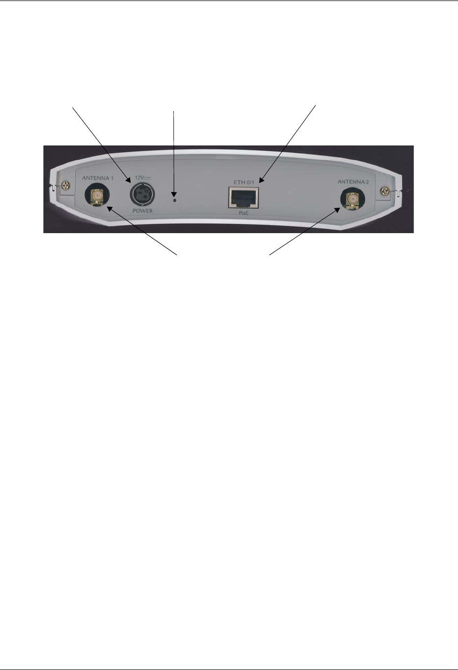
Reviewing the Rear Panel Design
Figure 2 shows the NetVanta 150 rear panel. The unit accommodates a 12 VDC power supply.
Figure 2. NetVanta 150 Rear Panel Layout
Rear Panel Interfaces
10/100BaseT Ethernet Interface
The ETH 0/1 port on the NetVanta 150 is an RJ-45 connector with Power over Ethernet capability. See
Table A-1 on page 25 for the Ethernet port pinouts. The Ethernet port provides the following:
• 10BaseT or 100BaseT with a single connector
• Auto-negotiation
•CSMA/CD
• IEEE 802.3 compatibility
• Auto MDI/MDIX
Reset Switch
10/100 BaseT Ethernet
PoE Port
Optional 12 V
Power Source
RP-SMA Antenna
Connectors

Unit Installation NetVanta 150 Wireless Access Point ABG Hardware Installation Guide
22 Copyright © 2006 ADTRAN, Inc. 61700412E1-34A
3. UNIT INSTALLATION
The instructions and guidelines provided in this section cover hardware installation topics such as wall
mounting and supplying power to the unit.
Installing the Antennas
The NetVanta 150 unit ships with two dual-band RP-SMA detachable antennas. These must be installed
before wall mounting the unit.
Mounting Options
The NetVanta 150 unit can be installed in a wallmount or tabletop configuration. The following section
provides step-by-step instructions for wall mounting.
To prevent electrical shock, do not install equipment in a wet location or during a
lightning storm.
Maximum recommended ambient operating temperature is 50°C.
Instructions for Attaching the Antennas
Step Action
1 Place either of the two antennas directly onto the antenna port on the rear panel labeled
Antenna 1. See Figure 2 on page 21 to locate the ports on the rear panel.
2 Twist the antenna onto the threads until it is secure.
3 Repeat step 2 with the second antenna, attaching it to the Antenna 2 port.
4 Once both antennas are secured, the antennas may be flexed at the joint to increase reception.
NetVanta 150 Wireless Access Point ABG Hardware Installation Guide Unit Installation
61700412E1-34A Copyright © 2006 ADTRAN, Inc. 23
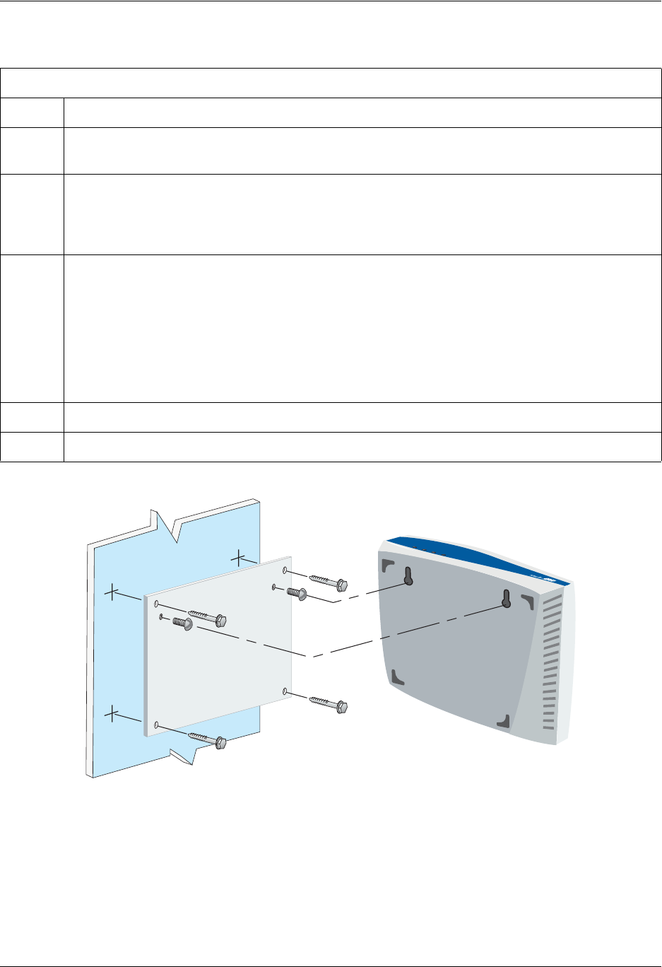
Wall Mounting
Figure 3. Wall Mounting the NetVanta 150 Unit
Instructions for Wall Mounting
Step Action
1 Decide on a location for the NetVanta 150 unit. Keep in mind that the unit needs to be mounted
at or below eye-level so that the LEDs are viewable.
2 Prepare the mounting surface by attaching a board (typically plywood, 3/ 4-inch to 1-inch thick)
to a wall stud.
Important! Mounting to a stud ensures stability. Using sheetrock anchors may not
provide sufficient long-term stability.
3 Install two #8 PAN headscrews (1 1/ 2-inch or greater in length) wood screws into the mounted
board, following these guidelines and referring to Figure 3:
• Screws should be spaced horizontally, approximately 5 inches apart. Find exact positioning
by using the location of the two keyed insets on the bottom of the NetVanta 300 Series unit
as a guide.
• Screws should be horizontally level with each other.
• Leave approximately 1/4 inch of the screws protruding from the board to allow the heads of
the screws to slide into place in the unit’s keyed insets.
4 Slide the keyed insets on the bottom of the unit’s chassis securely onto the screws.
5 Proceed to the steps given in Getting Started on page 24.
ST
A
T
WANDBU
TD
Unit Installation NetVanta 150 Wireless Access Point ABG Hardware Installation Guide
24 Copyright © 2006 ADTRAN, Inc. 61700412E1-34A
Getting Started
Supplying Power to the NetVanta 150 Unit
The NetVanta 150 unit can be powered either by the LAN Ethernet connection or through the 12 VDC
external supply. The Wall Supply is not included in shipment of this unit but can be requested from Adtran
or your reseller. See Product Support Information on page 9 for more information on contacting Adtran.
Connect to the NetVanta 150 Unit
1. Connect the NetVanta 150 unit to the PC using the ETH port on the back of the unit and the
appropriate Ethernet cable.
2. Supply power to the PC and the NetVanta 150 unit and begin the operating system boot up process.
During boot up, the PC will obtain an IP address from the NetVanta 150 unit DHCP server. By
default, both the DHCP and HTTP servers are enabled. The default IP address is 10.10.10.1.
3. Enter the unit’s IP address in your browser address line. The default IP address is 10.10.10.1.
4. You will then be prompted for the username and password (the default settings are admin and
password).
5. The initial GUI screen appears.
6. Click on Getting Started in the System menu on the left side of your screen and follow the
on-line instructions.
Factory Default Switch
• If the factory default switch is pressed during bootup, the unit will stay in bootstrap mode. Since the unit
has no serial port, Telnet has been built into the boot code. The default IP address is 10.10.10.1.
• If the factory default switch is pressed and held for 5 seconds after boot, the ETH interface on the
NetVanta 150 will default to 10.10.10.1 and all access policies will be removed from that interface.
• If the factory default switch is pressed for 30 seconds, a default configuration will overwrite your
existing configuration and reboot the unit.
The 10/100BaseT Ethernet interface MUST NOT be metallically connected to interfaces
which connect to the Outside Plant or its wiring. This interface is designed for use as an
intrabuilding interface only. The addition of primary protectors is not sufficient protection
to connect this interface metallically to OSP wiring.
For security purposes, you should set up an admin password immediately. Use the
Passwords page of the Web GUI to change this password.
The default switch must be pressed WHILE the power light is flashing green. Do not press
the default switch BEFORE the power light is flashing green, as this will cause boot to be
missed.

61700412E1-34A Copyright © 2006 ADTRAN, Inc. 25
APPENDIX A. CONNECTOR PIN DEFINITIONS
The following table provides the pin assignments for the NetVanta 150.
Table A-1. 10/100BaseT Ethernet Port Pinouts
Pin Name Description
1 TX1 Transmit Positive
2 TX2 Transmit Negative
3 RX1 Receive Positive
4, 5 — Unused
6 RX2 Receive Negative
7, 8 — Unused

NetVanta 150 Wireless Access Point ABG Hardware Installation Guide
26 Copyright © 2006 ADTRAN, Inc. 61700412E1-34A
"This device has been designed to operate with the antennas listed below, and having a maximum gain of
802.11a 3dBi and 802.11b/g 2dBi. Antennas not included in this list or having a gain greater than the
designed Antennas is strictly prohibited for use with this device. The required antenna impedance is 50
ohms."
Antenna Gain: IEEE 802.11a: 3dBi
IEEE 802.11b/g: 2dBi
Antenna Designation: Omni-directional Antenna
"To reduce potential radio interference to other users, the antenna type and its gain should be so chosen
that the equivalent isotropically radiated power (e.i.r.p.) is not more than that permitted for successful
communication."
. that the device for the band 5150-5250 MHz is only for indoor usage to reduce potential for harmful
interference to co-channel mobile satellite systems;
. the maximum antenna gain permitted (for devices in the 5250-5350 MHz band) to comply with the
e.i.r.p. limit; and
. the maximum antenna gain permitted (for devices in the 5725-5825 MHz band) to comply with the
e.i.r.p. limits specified for point-to-point and non point-to-point operation as appropriate, as stated in
section A9.2(3).
In addition, users should also be cautioned to take note that high power radars are allocated as primary
users (meaning they have priority) of 5250-5350 MHz and 5650-5850 MHz and these radars could cause
interference and/or damage to LE-LAN devices.

61700412E1-34A Copyright © 2006 ADTRAN, Inc. 27
Index
Numerics
10/100BaseT Ethernet interface 21
pinouts 25
A
admin password 24
antennas 22
B
boot up 24
C
connecting to unit 24
contents of shipment 19
customer service 9
D
default switch 24
E
Ethernet interfaces
LEDs 21
pinouts 25
F
factory default switch 24
features 18
front panel 20
G
getting started 24
I
installation 22
installing unit 22
interfaces 21
L
LEDs 20
M
mounting options 22
P
passwords page 24
physical description 20
pinouts
10/100BaseT 25
power over ethernet 24
product registration 9
R
rear panel 21
S
shipping contents 19
specifications 18
U
unpacking and inspecting the system 19
W
wall mounting 23
warranty 9
web GUI
passwords page 24

NetVanta 150 Wireless Access Point ABG Hardware Installation Guide
28 Copyright © 2006 ADTRAN, Inc. 61700412E1-34A