Contents
- 1. User Manual
- 2. User Manual Module
- 3. User Manual Regulatory
User Manual
jobAid
1
DESCRIPTION
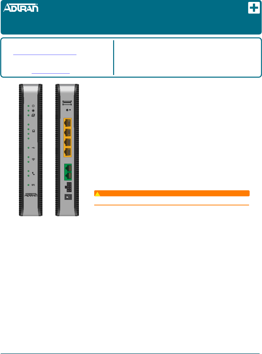
The ADTRAN 2 POTS/4GigE with 2.4+5.0 Gig WiFi is an Optical Network Unit (424RG
ONU) that converts signals being transmitted on optical fiber into electrical signals at a
customer location. The illustration at the left displays the front and rear of the 424RG ONU.
FEATURES
The 424RG ONU supports the following features:
■Two POTS (PHONE) Ports
■Four Ethernet Ports
■2.4 GHz and 5.0 GHz WiFi
■12 VDC Power Adapter
■USB Port
■UPS Connector
■Reset Button
Resetting the ONT
WARNING
!
All settings will return to Factory Defaults; registration provisioning will be lost.
A reset button is available if the 424RG ONU needs to be rebooted. The Reset button is
located just below the USB port on the rear of the 424RG ONU. To reset the 424RG ONU,
press the RESET button for 5 seconds or longer.
Voice Processing
POTS uses in-band signaling tones and currents to determine call status (for example, call request). Because POTS allows for the transfer of
audio signals below 3.3 kHz, POTS systems are also used for modems that allow data transmission (referred to as dial up connections).
Ethernet Interface
The 424RG ONU supports data service through four 10/100/1000Base-T Ethernet interfaces via RJ-45 connectors.
Power
Power is provided by a 12 VDC Power Adapter that is included with the 424RG ONU. The Power Adapter operates from a main power source
input of 100 to 240 VAC, 50/60 Hz, with a nominal output of 12 VDC. The total power consumption with WiFi enabled, 4 Ethernet Ports running
and both POTS lines off-hook is approximately 22.0 Watts. A connection for an optional un-interruptible power supply (UPS) is also provided.
UPS
The 424RG ONU provides an optional connection for an UPS. An UPS is a battery backup system designed to continue providing power when
the primary power source is lost. Power is supplied to the 424RG ONU by a local power source with battery backup that utilizes the AC power
at the customer premises and keeps the battery charged.
CLEI: BVMFG00A_ _
Product P/N: 1287781F2
Issue Date: July 2016
Document P/N: 61287781F2-22A
Documentation for ADTRAN® Carrier Networks products is available
for viewing and download directly from the ADTRAN Support
Community website.
Go to: https://supportforums.adtran.com/welcome
Registration is required.
ADTRAN offers training courses on our products, including customized
training and courses taught at our facilities or at customer sites.
For inquiries, go to: http://adtran.com/training
The following related online documents and resources provide additional information for this
product:
Total Access 5000 GPON OLT User Interface Guide
Total Access 5000 Series CLI Dictionary
Total Access 5000/5006 Engineering Guide
Total Access 5000 Series Fiber to the Premises Deployment Guide
ADTRAN 400 Series Residential Gateway ONT Basic Configuration Guide
ADTRAN 424RG
2 POTS/4GigE with 2.4+5.0 Gig WiFi
Optical Network Unit
WPS
S
RESET
USB
GE 4GE 3GE 2GE 1
PHONE 1PHONE 2
UPS12V
1
2
3
4
2.4
5.0
1
2
Front Rear
261287781F2-22A
Installation Steps
NOTICE
The 424RG ONU must sit upright using the stand provided. DO NOT
lay the ONT flat as it may overheat.
To install the 424RG ONU, refer to the figures on the first page and
complete the following steps.
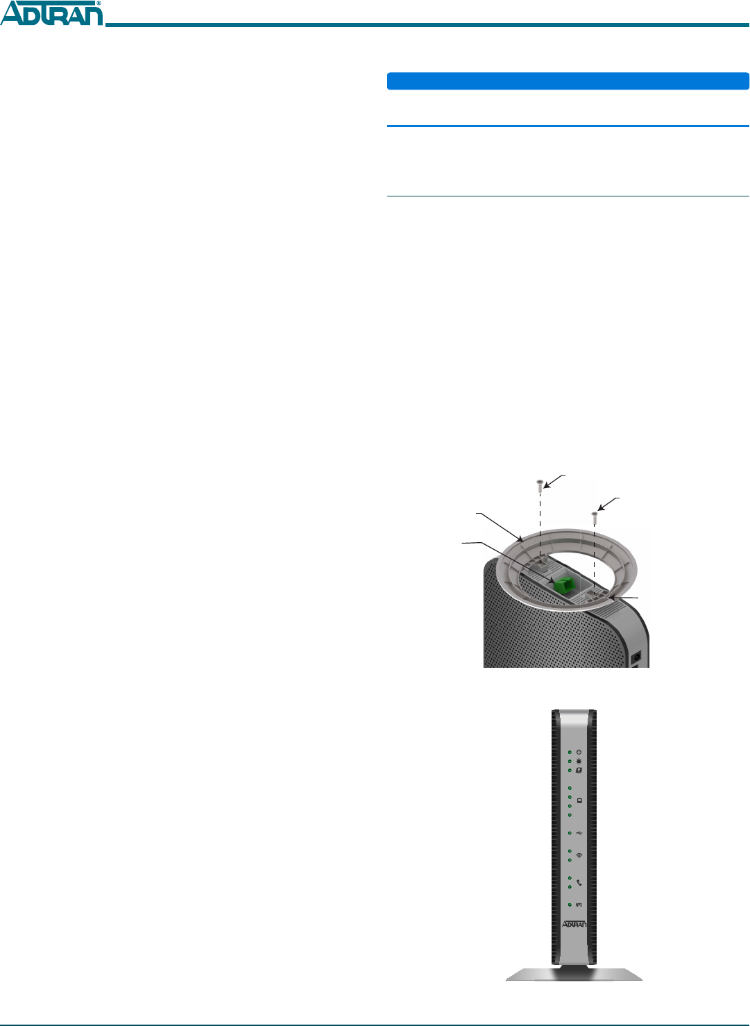
Step 1: Install the Base and Connect Fiber
Ensure the 424RG ONU is not located in direct sunlight and is not
located next to any thermal obstructions. To attach the 424RG ONU to
the base, refer to Figure 1 and complete the following steps:
1. Remove the two screws from the base of the 424RG ONU.
2. Position the 424RG ONU on the base.
3. Using the two screw provided, secure the base to the 424RG
ONU.
4. Thread the fiber cable through the opening in the base. If there
is excess fiber, carefully wrap it around the Fiber Tray.
5. Remove the plug from the SC/APC Connector and insert the
fiber cable. Retain this plug and insert it in the fiber connection
when the fiber cable is not connected. This will protect the
optical portion of the connection.
Figure 2 illustrates the 424RG ONU after the base has been
attached.
Figure 1. Attach 424RG ONU to Base and Connect Fiber
Figure 2. 424RG ONU with Base Attached
Screw
Fiber
Tray
SC/APC
Connector
Fiber
Opening
Screw
1
2
3
4
2.4
5.0
1
2
WiFi
The WPS or “Wi-Fi Protected Setup” function allows you to connect
wireless devices without entering the password in the device. This is
enabled by simultaneously pressing the button on the left-side of the
424RG ONU and the WPS button on the device which it is going to
link to for 5 seconds.
The 424RG ONU WiFi 802.11b/g /n/ac supports both 2.4 GHz and 5
GHz. When the WPS button on the rear of the 424RG ONU is turned
on (pressed in), the wireless network in your home is secure and
encryption is activated.
USB
There is a USB data connection on the rear of the 424RG ONU that
can be used for connection and communications with other
computers and electronic devices.
INSTALLATION
After unpacking the 424RG ONU, inspect it for damage. If damage is
noted, file a claim with the carrier and then contact ADTRAN. For
more information, refer to the warranty.
Installation consists of positioning the 424RG ONU on a desktop and
connecting POTS (PHONE), Ethernet, Fiber, and power.
Installation Guidelines
The following are guidelines for this installation.
■Read all warnings and cautions before installing or servicing the
424RG ONU.
■Do not locate the 424RG ONU in direct sunlight or next to any
thermal obstructions.
Installation Overview
To install the 424RG ONU, you will need to complete the following
steps:
■“Step 1: Install the Base and Connect Fiber”
■“Step 2: Connect POTS (PHONE)”
■“Step 3: Connect Ethernet”
■“Step 4: Connect Power”
■“Step 5: Connect USB (optional)”
Required tools
Standard technician tools and those listed below are required for
installing the 424RG ONU:
■Phillips-head screwdriver
■Two, RJ-11 connectors
■Four, RJ-45 connectors
■Wire strippers
■RJ-11 and RJ-45 crimpers
■PON power meter with wavelength filtering
■Fiberscope or videoscope
For fiber optic connections, the following is required:
■ODC Fiber cleaning tool
61287781F2-22A 3
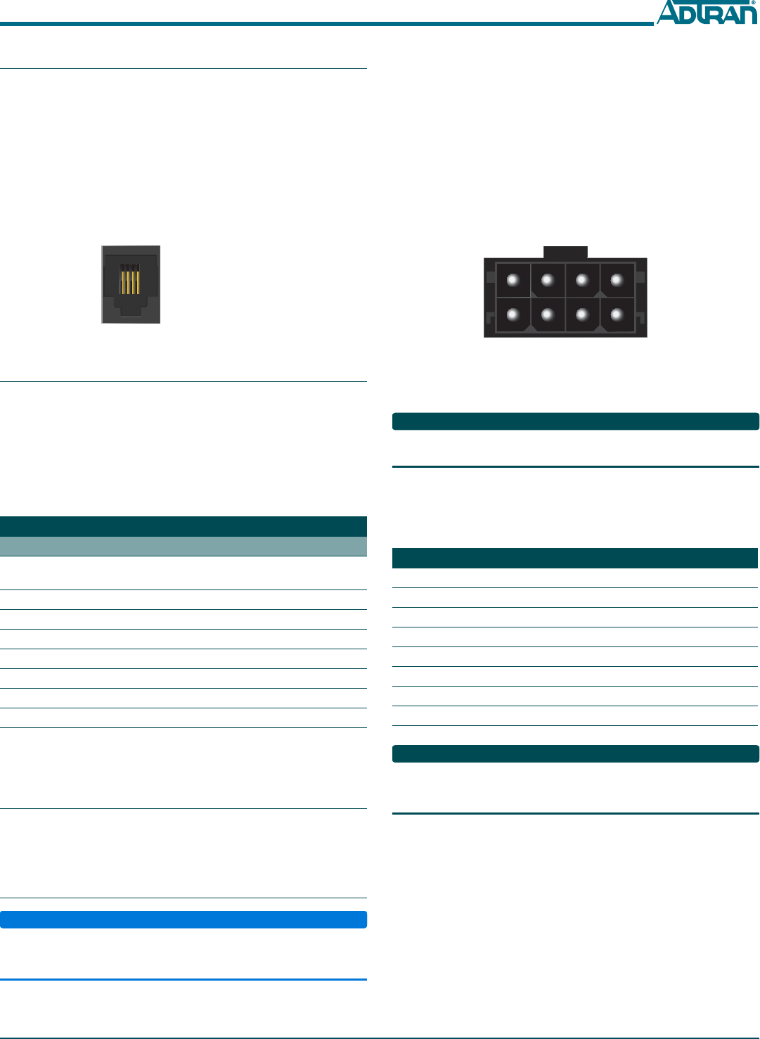
Step 2: Connect POTS (PHONE)
If POTS cables are not available, use Figure 3 and the following
procedure to create the POTS cables:
1. Trim the insulation for the subscriber POTS cables.
2. Refer to the illustration below and connect the twisted-pair Tip
(green) and Ring (Red) to the RJ-11 connector using an RJ-11
crimper.
3. Insert the RJ-11 connector in the appropriate PHONE 1 or
PHONE 2 jack.
Figure 3. POTS (PHONE) Connection
Step 3: Connect Ethernet
The 424RG ONU supports four 1 Gigabit (10/100/1000Base-T)
connections (GE 1 to GE 4).
If Ethernet cables are not available, use the following procedure and
table to create the Ethernet cables:
1. Trim the insulation for the subscriber Ethernet cable.
2. Connect the wires per the following table using an RJ-45
Crimper.
3. Insert the CAT 6 rated cable in the appropriate GE 1 through GE
4 ports on the rear of the 424RG ONU.
Step 4: Connect Power
Plug the supplied 12 VDC Power Adapter into the 12V connection on
the rear of the chassis. Connect the AC plug to a standard 120 VAC
outlet.
Step 5: Connect USB (optional)
NOTICE
DO NOT connect the Power Adapter and an UPS at the same time as
this will cause damage to the 424RG ONU. The ONT can be powered
by either power source, but not both simultaneously.
Ethernet RJ-45 Pin-out
Pin Name Description Color Code
1 TRD0+ Transmit/Receive Positive White/
Orange
2 TRD0- Transmit/Receive Negative Orange
3 TRD1+ Transmit/Receive Positive White/Green
4 TRD2+ Transmit/Receive Positive Blue
5 TRD2- Transmit/Receive Negative White/Blue
6 TRD1- Transmit/Receive Negative Green
7 TRD3+ Transmit/Receive Positive White/Brown
8 TRD3- Transmit/Receive Negative Brown
1 2 3 4
1 = Not Connected
2 = Tip
3 = Ring
4 = Not connected
The 424RG ONU can typically use an un-interruptible power supply
(UPS) if desired. Power is supplied to the 424RG ONU by a local
power source with battery backup that utilizes the AC power at the
customer premises. The UPS powers the 424RG ONU and functions
as a battery backup unit (BBU) supplying continuous 12 VDC. Refer
to the installation material that is provided with the UPS when
installing the BBU.
UPS Connector
Connect the UPS to the 8-pin MOLEX connector labeled “UPS”
located on the rear of the SFU ONT chassis. Figure 4 illustrates the
MOLEX connector on the rear of the ONT.
Figure 4. 8-Pin Molex Connector
The UPS Power/Alarm Connections Table below defines each pin on
the connector.
NOTE
ADTRAN offers a UPS Cable assembly (P/N 1287402G1) for this
connector.
UPS Power/Alarm Table
The following table indicates which pin is associated with each alarm
provided through a UPS connection.
NOTE
If an UPS is being used and is disconnected, the 424RG ONU is not
protected from power outages, and will send a “Battery Missing”
alarm to the OLT.
Pin-Out Description Alarm
1 Power Input (+12 VDC) -
2UPS Status - On Battery 1
3 UPS Status - Battery Missing 2
4 Signal Return -
5Power 12 V Return -
6 UPS Status - Replace Battery 3
7 UPS Status - Low Battery 4
8 No Connection -
C A U T I O N
C A U T I O N
!
SUBJECT TO ELECTROSTATIC DAMAGE
OR DECREASE IN RELIABILITY.
HANDLING PRECAUTIONS REQUIRED.
Warranty: ADTRAN will replace or repair this product within the warranty period if it does not
meet its published specifications or fails while in service. Warranty information can be
found online at www.adtran.com/warranty.
Trademarks: Brand names and product names included in this document are trademarks,
registered trademarks, or trade names of their respective holders.
©2016 ADTRAN, Inc. All Rights Reserved.
ADTRAN CUSTOMER CARE:
From within the U.S. 1.800.726.8663
From outside the U.S. +1 256.963.8716
PRICING AND AVAILABILITY 1.800.827.0807
*61287781F2-22A*
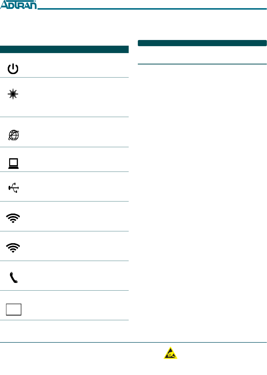
LED STATUS
The LEDs are located beneath the plastic housing and are only visible
after power has been applied. The following table provides the LED
status during normal operations.
Label Status Indication
POWER
Off
Green
AC or battery off
No Failure
FIBER
✷
Off
Green
Green Flashing
Fast
No connection to the OLT,
open fiber, failure at the ONT,
or power is Off
Signal present and is within
operating range
Ranging in Progress
INTERNET
Off
Green
No IP address configured on
WAN Interface, or Power is
Off
WAN Interface is configured
with IP address
GE 1-4
✷
Off
Green
Green Flashing
Fast
Link is down or not equipped
Link is up
Data is being sent or received
USB
✷
Off
Green
Green Flashing
Fast
Power Off or no device con-
nected
Device connected
Data is being sent or received
2.4GHZ
✷
Off
Green
Green Flashing
Fast
Power is Off, or Wireless
2.4GHz is Disabled
Wireless 2.4GHz is Enabled
Data is being sent or received
on 2.4GHz
5GHZ
✷
Off
Green
Green Flashing
Fast
Power is Off, or Wireless 5GHz
is Disabled
Wireless 5GHz is Enabled
Data is being sent or received
on 5GHz
PHONE 1-2
✷
Off
Green
Green Flashing
Slow
Unequipped or on-hook and
not ringing
Line is off-hook
Line in ringing state
WPS
✷
Off
Green
Green Flashing
Fast
Power Off or WPS is Disabled
WPS is Enabled
WPS push button pressed and
device is ready to accept con-
nection
REGISTRATION ID
Registration ID is performed by Serial Number Activation. This
occurs when the 424RG ONU is “Discovered” by the OLT.
NOTE
If AOE Auto Upgrade is active, a new 424RG ONU installation will be
detected and a fast blinking FIBER LED will indicate a new software
download has commenced. This may take 5 - 10 minutes to complete.
SPECIFICATIONS
■Electrical
♦Voltage: 12 Volts typical
♦Minimum Voltage: 10 Volts
♦Maximum Voltage: 13.9 Volts
♦Power Consumption: Typical 25.0 watts
■Physical
♦10.8 inches high (27.4 centimeters)
♦7.4 inches deep (18.8 centimeters)
♦ 3.2 inches wide (8.1 centimeters)
♦Weight: 1 pounds (0.45 kilograms)
■Environmental
♦Operational Temperature: 32°F to +104°F (0°C to +40°C)
♦Storage Temperature: –4°F to 122°F (–20°C to +50°C)
♦Relative Humidity: 90%, noncondensing
■Optical
♦TX min power: +0.5 dBm
♦TX max power: +5.0 dBm
♦RSSI max sensitivity: –27.0 dBm
♦R.0X overload: –8.0 dBm
♦TX wavelength: 1310 nm typical
♦RX wavelength: 1490 nm typical
MAINTENANCE
The 424RG ONU does not require routine hardware maintenance for
normal operation. ADTRAN does not recommend that repairs be
attempted in the field. Repair services may be obtained by returning
the defective unit to ADTRAN. Refer to the warranty for further
information. Field support for software is provided through upgrade
facilities.
SAFETY AND REGULATORY COMPLIANCE
Refer to the Safety and Regulatory Compliance Notice for this
product (P/N 61287781F2-17) for detailed safety and regulatory
information.
Consultez l'avis sur la sécurité et la conformité à la réglementation
pour ce produit (61287781F2-17) pour obtenir des renseignements
détaillés sur la sécurité et la réglementation.