ADTRAN SR310N 4 Port ADSL2+ 11n 150Mbps Router User Manual UT300 R
SmartRG, Inc. 4 Port ADSL2+ 11n 150Mbps Router UT300 R
ADTRAN >
Exhibit 08 Users Manual
4 Port ADSL2+ 11n 150Mbps Router
SR310N
USER MANUAL

ADSL MODEM USER MANUAL
- 2 -
CONTENTS
1. OVERVIEW ................................................................................................................................. 4
1.1 ABOUT ADSL AND ADSL 2+ ............................................................................ 4
1.2 DEVICE INTRODUCTION ................................................................................ 4
1.3 LED STATUS INDICATION ............................................................................... 5
1.4 PROTOCOLS ................................................................................................... 5
1.5 FEATURES ....................................................................................................... 5
1.6 ABOUT WIRLESS ADSL .................................................................................. 6
2. HARDWARE INSTALLATION AND SOFTWARE CONFIGURATION ............................ 7
2.1 SYSTEM REQUIREMENT ............................................................................... 7
2.2 HARDWARE INSTALLATION ........................................................................... 7
2.3 SOFTWARE CONFIGURATION ....................................................................... 8
3. PROTOCOL CONFIGURATION ........................................................................................... 10
3.1 CONFIGURATION GUIDE ............................................................................. 10
3.2 RFC1483 BRIDGE CONFIGURATION ........................................................... 12
3.3 PPPOA AND PPPOE CONFIGURATION ....................................................... 12
4. APPLICATION OF DHCP ....................................................................................................... 16
4.1 TCP/IP PROTOCOL CONFIGURATION......................................................... 16
4.2 MODEM CONFIGURATION ........................................................................... 16
5. OTHER FUNCTIONS AND CONFIGURATION .................................................................. 18
5.1 STATUS CHECKING ...................................................................................... 18
5.2 CONFIGURATION OF MODEM’S IP ADDRESS AND PASSWORD .............. 19
5.3 WIRELESS CONFIGURATION ...................................................................... 20
6. RESET TO DEFAULT SETTING ............................................................................................ 24
7. SPECIFICATION ...................................................................................................................... 25
7.1 POWER SUPPLY ........................................................................................... 25
7.2 STANDARDS .................................................................................................. 25
7.3 ENVIRONMENT REQUIREMENTS ............................................................... 25
APPENDIX ..................................................................................................................................... 26
APPENDIX A. TROUBLESHOOTING .................................................................. 26
APPENDIX B. SPLITTER CONNECTION ............................................................ 27
APPENDIX C. CONFIGURATION OF TCP/IP PROTOCOL ................................. 27
APPENDIX D. SHIPPING LIST ............................................................................ 29
Reference Standards

ADSL MODEM USER MANUAL
- 3 -
Related Documents
Definition & Acronyms
ATU-C ADSL Transceiver Unit, Central Office End
ATU-R ADSL Transceiver Unit, Remote Terminal End
FEXT Far-end Cross Talk
HDSL High-rate Digital Subscriber Line
POTS Plain Old Telephone Service
PSTN Public Switched Telephone Network
WINS Windows® Internet Name Server
ADSL Asymmetric Digital Subscriber Line
OAM Operations, Administration And Maintenance
QAM Quadrature Amplitude Modulation
DMT Discrete Multitone
DSL Digital Subscriber Line
FEC Forward Error Correction
ATM Asynchronous Transfer Mode
WAN Wide Area Network
PRD Pseudo-random Downstream
PRU Pseudo-random Upstream
LAN Local Area Network
PVC Permanent Virtual Circuit
SVC Switched Virtual Circuit
PPP Point to Point protocol
DNS Domain Name Server
VPI Virtual Path ID
VCI Virtual Circuit ID
DSL Digital Subscriber Line
IP Internet Protocol
CO Central Office
EC Echo Canceling
ADSL MODEM USER MANUAL
- 4 -
1. OVERVIEW
1.1 ABOUT ADSL AND ADSL 2+
ADSL MODEM is a broadband Internet access device,which utilizes the high frequency segment of the
phone line to transmit high-speed data without interfering with the voice transmission. The frequency of ADSL
signal is higher than that of voice, so voice and ADSL signal can coexist in one line by using a splitter to
insulate each from the other. ADSL data transfer on the asymmetry way. The upload speed is up to 1Mbps and
download speed is up to 8Mbps. It is an ideal device for broadband access.
Transmission performance of ADSL2 is improved comparing with the first generation of ADSL. These
improvements are mainly concerned with long distance, anti-line-loss, anti-noise, etc. By doubling the
transmission bandwidth, ADSL2+ has implemented a downlink rate as high as 24 Mbps. Therefore, Internet
applications such as synchronous transmission of multi video stream, online games and huge capacity of
downloading files are made possible.
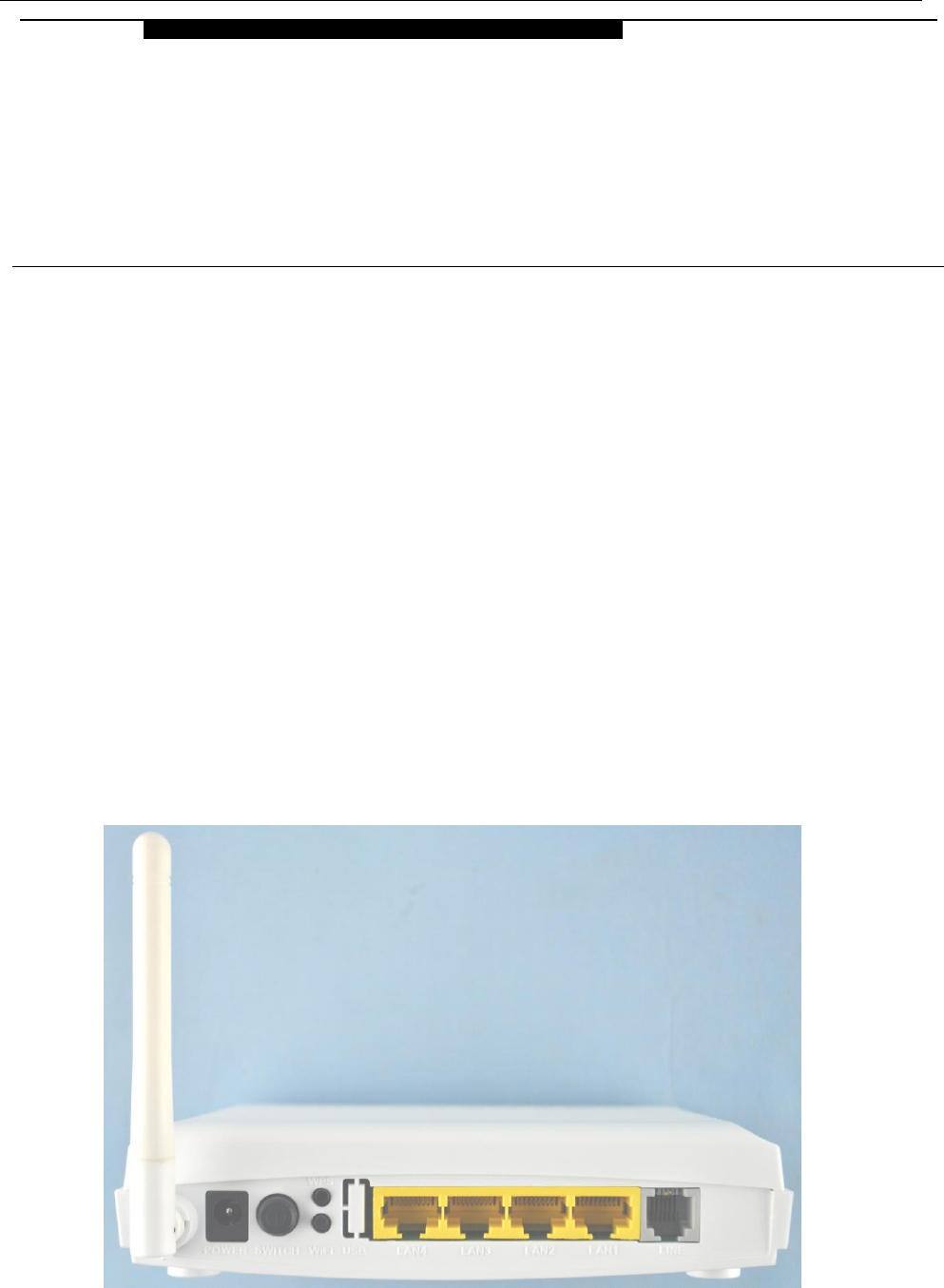
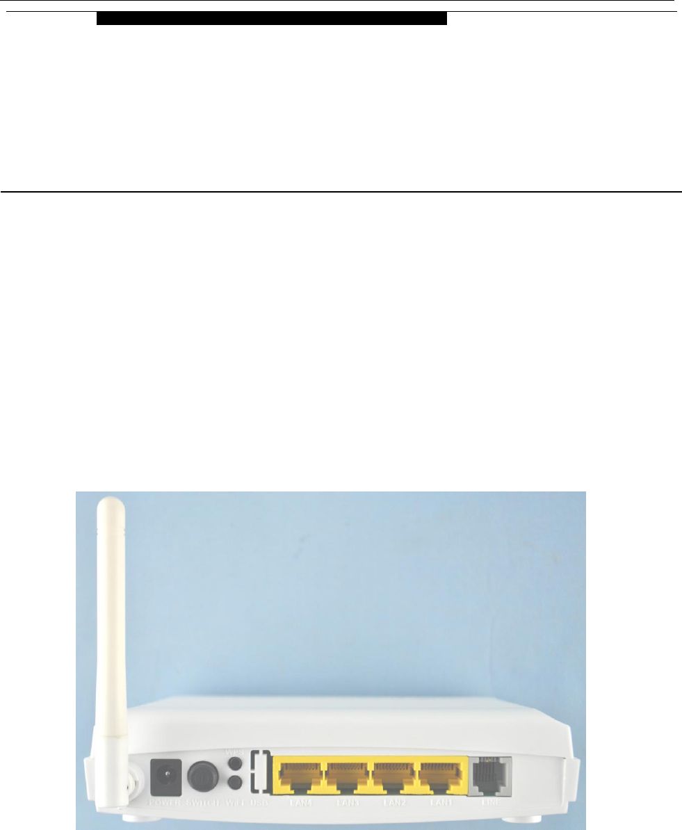
1.2 DEVICE INTRODUCTION
Figure 1.1
1
OVERVIEW

ADSL MODEM USER MANUAL
- 5 -
Interface introduction:
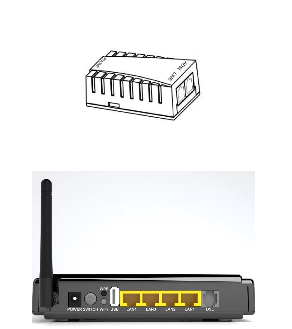
a) Power Interface: 12V DC, 500mA. .
b) Switch: To turn on or turn off the power.
c) WIFI: To switch on or switch off the WIFI.
d) LAN1~LAN4: Connect Ethernet port of the Gateway with 10/100BASE-T port of the computer using the
network cable that comes with the modem
e) Line: Connected with phone line or “ADSL” port of the splitter.
1.3 LED STATUS INDICATION
Table 1.1
Steady light
Flashing
Fast flashing
Off
POWER (green)
Power on
/
/
Power off
DSL(green)
The modem is in
good connection
The modem is boot
OK
In handshaking status
Power off
Internet(green)
Route mode and
obtained IP address
Route mode and
Data transmitting or
receiving
/
Bridge mode or no Data
transmitting or receiving
LAN(1-4)
(green)
Ethernet line is
connected to PC
Ethernet is transmitting
data
Ethernet line not connected
properly
WLAN(green)
/
/
Wireless is transmitting
data
Disable Wireless
WPS(green)
/
/
Start WPS
Disable WPS
1.4 PROTOCOLS
ADSL Modem supports the following protocols:
1. PPPoA(PPP over ATM ) LLC encapsulation or VCMUX encapsulation (RFC2364)
2. PPPoE (PPP over Ethernet) LLC encapsulation or VCMUX encapsulation (RFC2516)
3. 1483 bridge(1483 Bridged IP over ATM)LLC encapsulation or VCMUX encapsulation (RFC1483)
4. 1483 routing(1483 Routing IP over ATM)LLC encapsulation or VCMUX encapsulation (RFC1483)
5. Classical IP over ATM (RFC1577)
1.5 FEATURES
1. Supports ANSI T1.413 ISSUE 2, ITU G.992.1 (G.DMT), ITU G.992.2 (G.LITE), ITU G.992.3 (ADSL2), ITU
G.992.5 (ADSL2+), Annex M.
2. Web-based configuration and monitoring.
3. Supports up to 8 PVCs.
4. Routing function.
5. NAPT、DHCP function.

ADSL MODEM USER MANUAL
- 6 -
6. Support GUI Upgrading.
7. ATM management function.
8. Wireless access distance is more than 150m
1.6 ABOUT WIRLESS ADSL
An ADSL MODEM is a broadband Internet access device, which utilizes the high frequency segment of
the phone line to transmit high-speed data without affecting the voice transmission. The frequency of the
ADSL signal is higher than that of voice, so voice and ADSL signal can coexist in one line by using a splitter to
insulate each from the other. ADSL data transfer adapts the asymmetry model. It supports upload
transmission speed up to 2Mbps and download speed up to 24Mbps for ADSL2+. ADSL is an ideal device for
broadband access.
But the ADSL users are also limited by the cable and can’t move freely. Wireless ADSL is a new device
that integrates WLAN and ADSL functions. User can slip the leash to visit Internet expediently as long as they
install WLAN card into their computer. The device can be utilized in company, hotel, cafe, airport, station, and
financial institution and home where there are many mobile users and the network infrastructures are difficult to
establish. The wireless ADSL supports 802.11b, 802.11b+g, 802.11g, 802.11n and 802.11b+g+n mode with
maximum data rate 150Mbps.
ADSL MODEM USER MANUAL
- 7 -
2. HARDWARE INSTALLATION AND SOFTWARE
CONFIGURATION
2.1 SYSTEM REQUIREMENT
A computer with a network card with Ethernet interface.
2.2 HARDWARE INSTALLATION
2.2.1 HARDWARE CONNECTION
Figure 2.1
To go online and make phone calls simultaneously, please refer to Appendix B: SPLITTER
CONNECTION.
2.2.2 INSTALLATION STEPS
1. Connect line port of the ADSL MODEM to telephone jack with the telephone cord that comes with the
2
HARDWARE INSTALLATION AND
SOFTWARE CONFIGURATION

ADSL MODEM USER MANUAL
- 8 -
modem.
2. Connect Ethernet port of the ADSL MODEM to Ethernet port of the computer using the network cable that
comes with the modem.
3. Plug in the power cord , and turn on the power.
2.3 SOFTWARE CONFIGURATION
2.3.1 PREPARATION BEFORE SOFTWARE INSTALLATION
Before the installation, please confirm information below or consult with the ADSL service provider. Table
2.1 shows all the information needed to configure for different protocols.
Table 2.1
Protocol
Virtual Dial Mode
Private Line Mode
PPPOE
PPPOA
1483 Bridged
Necessary
Information
VPI
VPI
VPI
VCI
VCI
VCI
User name
User name
Password
Password
2.3.2 COMPUTER CONFIGURATION
The default factory-set IP Address for the ADSL MODEM is: 192.168.1.1. The Subnet Mask is:
255.255.255.0. Users can configure ADSL MODEM through an Internet browser. ADSL MODEM can be used
as a gateway and DNS server and users need to set the computer’s TCP/IP protocol as follow:
1. Set the computer at same Internet segment with ADSL MODEM so as to enter ADSL MODEM
configuration page through a browser.
2. Set the computer’s gateway’s IP address the same as the ADSL Modem’s.
3. Set the computer’s DNS server’s IP address the same as the ADSL Modem’s or that of an effective DNS
server.
If the user has any question regarding the computer’s TCP/IP protocol, please refer to APPENDIX C:
TCP/IP PROTOCOL CONFIGURATION.
2.3.3 ADSL MODEM CONFIGURATION
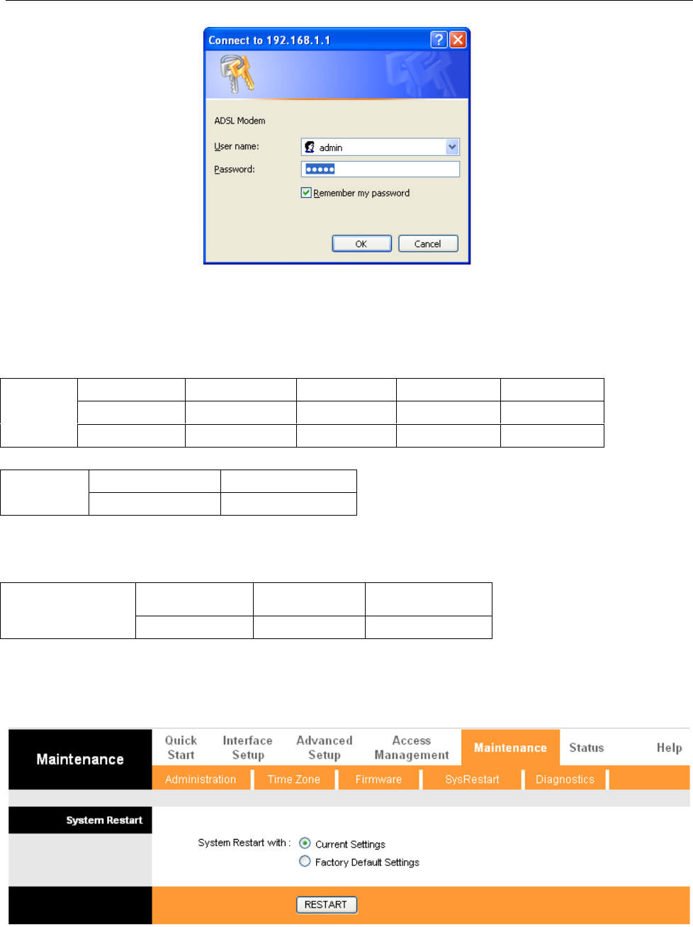
Open the browser; input http://192.168.1.1 in the address column. Press “Enter” key then the entry dialog
box will pop up as Figure 2.2, Input username: admin, and password: 1234 then press “OK”. The ADSL
MODEM configuration page will be shown.
ADSL MODEM USER MANUAL
- 9 -
Figure 2.2
2.3.4 ADSL MODEM WORK MODE CONFIGURATION
1. For different protocols, the users need to set ADSL Modem accordingly as listed below:
Table 2.2
PPPoE
PPPoA
PVC
Protocol
Use DNS
User Name
Password
√
PPPoE
Enable
√
√
√
PPPoA
Enable
√
√
1483 Bridged
PVC
Default route
√
Disable
Note: √ means configure according to ADSL service provider’s instructed value.
PPPoE can also be realized via third party dialup software.
User Manual
Reference Chapter
PPPoE
PPPoA
1483 Bridged
3.3
3.3
3.2
2. After getting through every page for parameters set-up, click “save” to save the value in ADSL MODEM
3. Click the “SysRestar” on “Maintenance” Tab to enter the page as Figure 2.3.You can choose “Current
Settings” and Click “Restart” button to reboot the ADSL MODEM.(You can also choose the “factory
default settings” in order to restart the modem to default configuration.)
Figure 2.3
ADSL MODEM USER MANUAL
- 10 -
3. PROTOCOL CONFIGURATION
If the configuration is bridge encapsulation, there is no need to configure any more parameters. Only need
to use the third party dial-up software to connect the Internet.
Totally, this router supports:PPPoA、PPPoE、Bridging. For detail configuration information, please check
the following configuration guide.
3.1 CONFIGURATION GUIDE
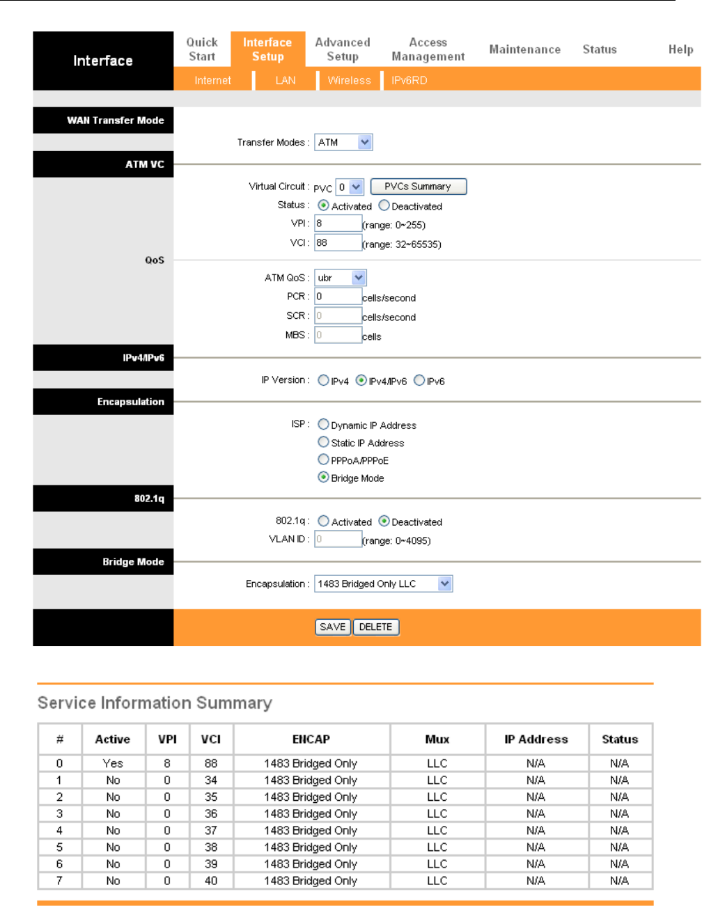
Click “Internet” on “Interface Setup” Tab. You can modify the configuration.
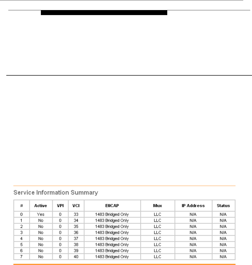
Note: At most we can have eight connections.
You can got the detail about the default seven connections after you click the button “PVCs
Summary”as Figure 3.1
Figure 3.1
If you need to add a new connection, please modify an existing connection
For example, if you need to add a new connection “VPI/VCI=8/88” (The correct PVC (VPI/VCI) you can
get from the ISP.) instead of the connection “VPI/VCI=0/33”.
You can modify as Figure 3.2 and choose “PVC0” and find the change as Figure 3.3.
3
PROTOCAL CONFIGURATION
ADSL MODEM USER MANUAL
- 11 -
Figure 3.2
Figure 3.3
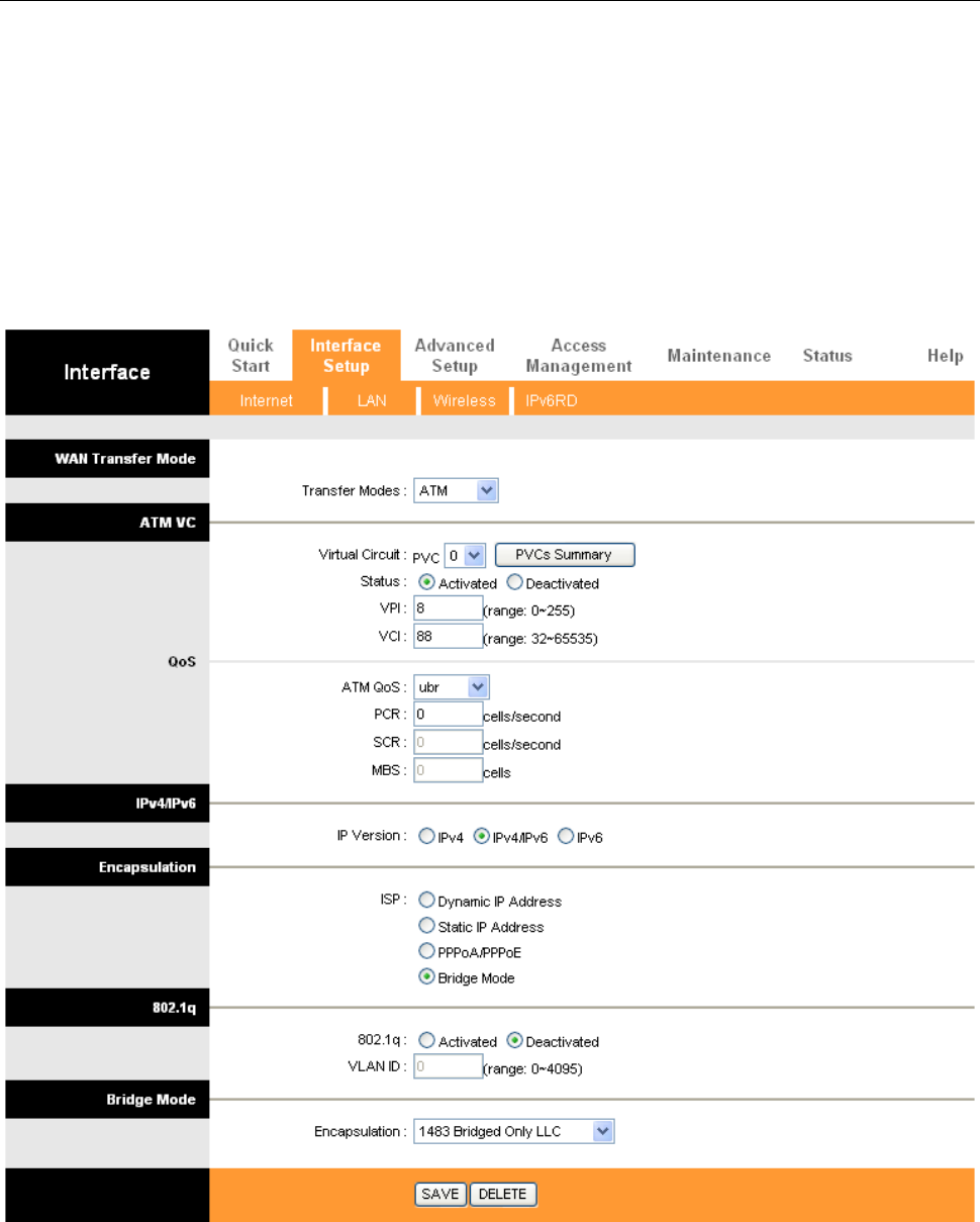
The Modem supports three ADSL protocol modes. Choose the protocol which is appointed by ISP and
PVC encapsulation. Below, we introduce the configuraion of the three protocol modes.
ADSL MODEM USER MANUAL
- 12 -
• PPP over ATM (PPPoA) • PPP over Ethernet (PPPoE)
• Bridging
Some connection lines need to confirm the LLC or VC, if you can’t confirm, please don’t modify the
default value or ask your ISP.
3.2 RFC1483 BRIDGE CONFIGURATION
If you get the correct PVC (VPI/VCI) which you can get from the ISP, you don’t need modify another
parameter. Click “save” to save configuration as Figure 3.4.
Figure 3.4
3.3 PPPOA AND PPPOE CONFIGURATION
PPPoE is also known as RFC 2516. It is a method of encapsulating PPP packets over Ethernet.
PPPoA is also known as RFC2364 and named as Peer to Peer Protocol over ATM. As PPPoE, it also has all
the features of PPP. Although it’s based on ATM protocol, the setting of all the other parameters is similar with
ADSL MODEM USER MANUAL
- 13 -
PPPoE. So we only introduce PPPoE in detail here.
In Figure 3.4, select PPP over Ethernet (PPPoE), entering the configuration interface, as Figure 3.5
Figure 3.5
ADSL MODEM USER MANUAL
- 14 -
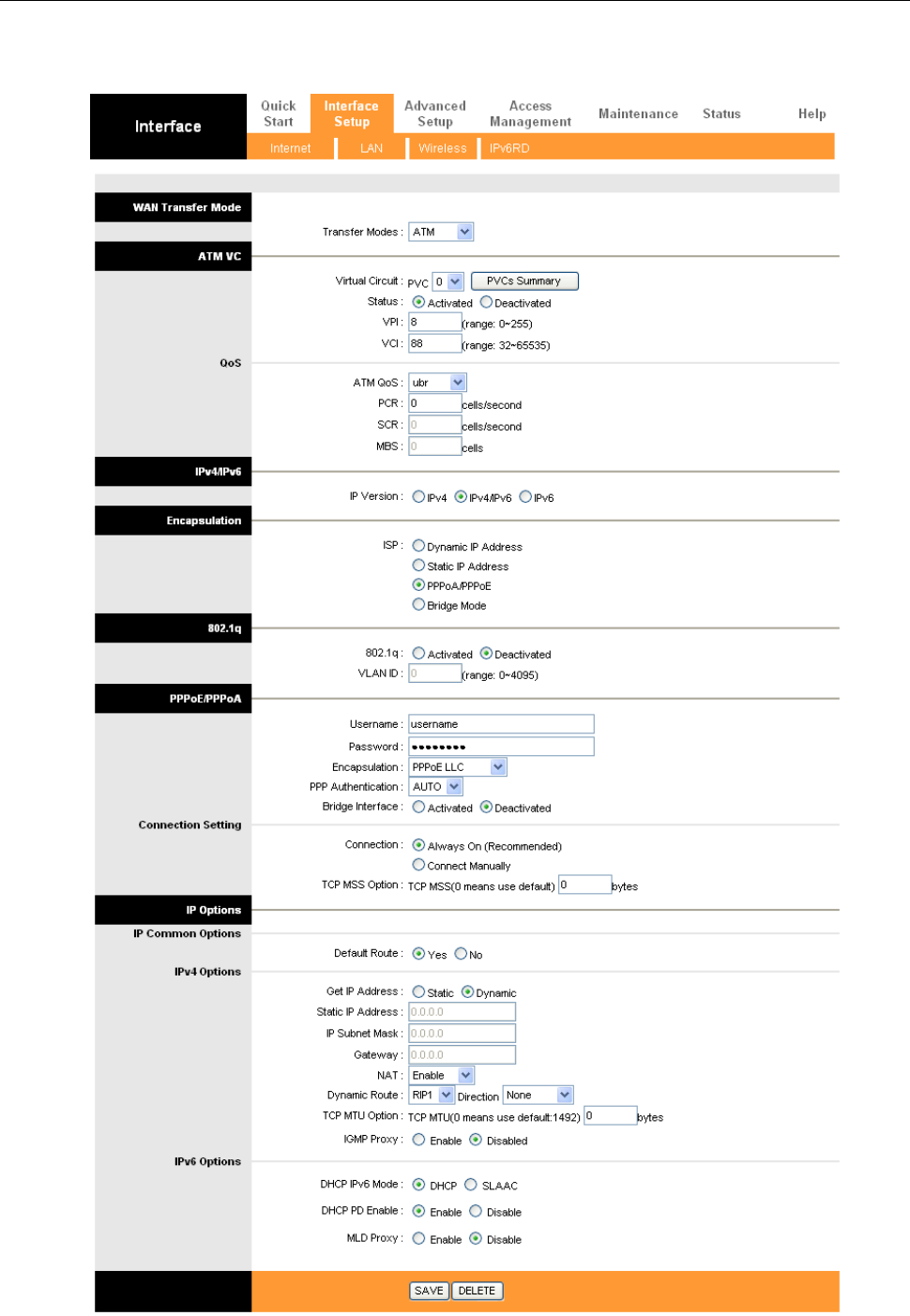
In Figure 3.4, select PPPoA from “Encapsulation”entering the configuration interface, as Figure 3.6
Figure 3.6

ADSL MODEM USER MANUAL
- 15 -
Select “Get IP Address Dynamic”and enter Severvice name、username、password.
Broadband User Name: Your account from ISP to access Internet.
Password: Input the password assigned by your ISP.

ADSL MODEM USER MANUAL
- 16 -
4. APPLICATION OF DHCP
Apart from being a modem, ADSL Modem can also support router and DHCP applications, which are
especially applicable for small business, small scale LAN, net-café, etc.
The ADSL Modem can work as a router and DHCP sever without proxy server. The configuration steps are
shown below:
4.1 TCP/IP PROTOCOL CONFIGURATION
1. Set IP address as “Automatically obtain IP address”;
2. Set gateway’s IP the same as Modem’s;
4.2 MODEM CONFIGURATION
1. Set protocol as described in Chapter 3.
2. DHCP sever settings:
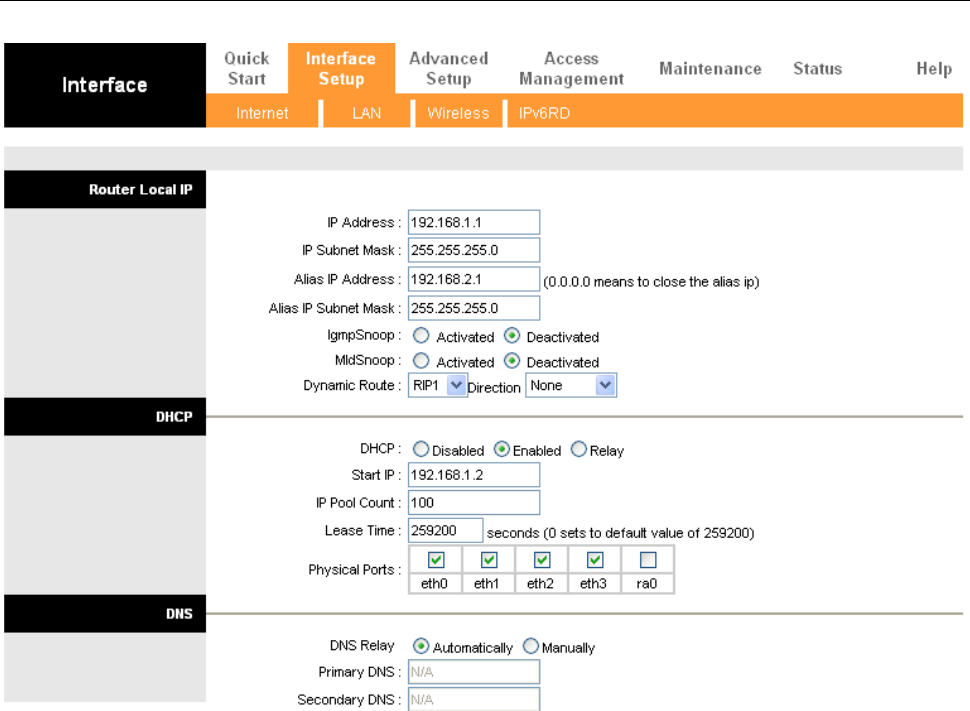
a) Click “lan” label of Page “Interface Setup”.
Define DHCP starting IP Address and IP Pool Count shown as Figure 4.1.
b) Fill in the starting IP address. Here we will use 192.168.1.2 as an example.
c) Do not change other options. Click “Save” to save the config.
4
APPLICATION OF DHCP
ADSL MODEM USER MANUAL
- 17 -
Figure 4.1

ADSL MODEM USER MANUAL
- 18 -
5. OTHER FUNCTIONS AND CONFIGURATION
5.1 STATUS CHECKING
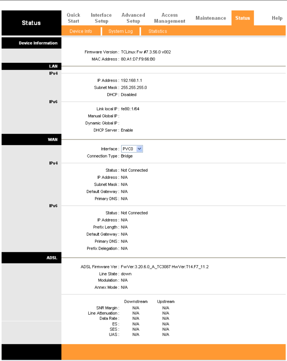
The working status of ADSL MODEM can be monitored by some pages.
1. Overview of Device Information
As shown in Figure 5.1, the information of Firmware Version, ADSL firmware Version, ADSL link status,
link speed and LAN interface can be viewed on this page.
5
OTHER FUNCTIONS AND
CONFIGURATION
ADSL MODEM USER MANUAL
- 19 -
Figure 5.1
5.2 CONFIGURATION OF MODEM’S IP ADDRESS AND PASSWORD
1. CONFIGURATION OF MODEM’S IP ADDRESS
As a network device, ADSL Modem has its own IP address and MAC address. The factory sets the ADSL
Modem at a default IP address of 192.168.1.1 and subnet mask of 255.255.255.0. The user can configure these

ADSL MODEM USER MANUAL
- 20 -
addresses through the LAN page.
2. Configuration of administrator’s password and user’s password
When logging on the setting page of ADSL Modem, the system requires user name and password to verify
for permission. The default administrator’s account is “admin” and the default password for this account is
“1234”. The user, through the user configuration tab on Administration page, can change the passwords.
(Attention: please remember the password after changing otherwise you will not be able to change
configuration after saving.)
5.3 WIRELESS CONFIGURATION
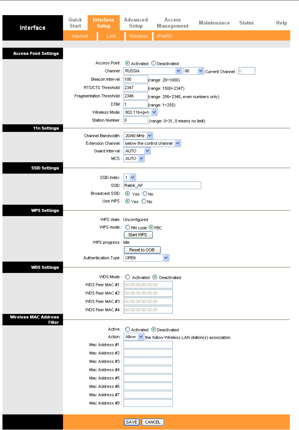
Press “WIRELESS” on the top of web pages to enter wireless section. You can select to configure
wireless setup, security and management.
5.3.1 WIRELESS SETUP
Click “WIRELESS” on the top menu to setup basic wireless parameters. In default, check “Access Point”
box to launch wireless AP.
5.3.1.1.Access Point Settings
SSID (Service Set Identifier): The mobile users cannot access WLAN until setting their SSID as the same
value of the wireless ADSL. The SSID value of the ADSL is “default”
Current Channel:To denote the different frequency of wireless signals whose value is from 1 to 11. The
default value is”11”. If there are more than one APs located in the same area, each of them must works at
different channels to reduce interference. For Example: Three APs are install in the same place, the AP’s
channel should be 1,6 and 11 respectively.
Wireless mode: The default setting is 802.11b+g+n (Mixed mode). If you do not know or have among 11n
11g and 11b devices in your network, then keep the default setting
Beacon interval: The Beacon Interval value indicates the frequency interval of the beacon. Enter a value
between 20 and 1000. A beacon is a packet broadcast by the Router to synchronize the wireless network.
RTS/CTS Threshold: The RTS (Request To Send) threshold (number of bytes) for enabling RTS/CTS
handshake. Data with its frame size larger than this value will perform the RTS/CTS handshake. Setting this
attribute to be larger than the maximum MSDU (MAC service data unit) size turns off the RTS/CTS
handshake. Setting this attribute to zero turns on the RTS/CTS handshake Enter a value between 1500 and
2347.
DMIT: This value, between 1 and 255, indicates the interval of the Delivery Traffic Indication Message
(DTIM).
ADSL MODEM USER MANUAL
- 21 -
Figure 5.3

ADSL MODEM USER MANUAL
- 22 -
5.3.1.2. Multiple SSID’S Settings
SSID Index, SSID: The SSID is the unique name of a wireless access point (AP) to be distinguished from another.
For security propose, change the default name to a unique ID name to the AP which is already built-in to the
router’s wireless interface. It is case sensitive and must not excess 32 characters. Make sure your wireless clients
have exactly the SSID as the device, in order to get connected to your network.
Broadcast SSID: Select Yes to hide the SSID in so a station cannot obtain the SSID through passive scanning.
Select No to make the SSID visible so a station can obtain the SSID through passive scanning.
Authentication Type: To prevent unauthorized wireless stations from accessing data transmitted over the
network, the router offers highly secure data encryption, known as WEP.&WPA. If you require high security for
transmissions, there are two alternatives to select from: 64-bit WEP and 128-bit WEP. WEP 128 will offer
increased security over WEP 64.
You can disable or enable with WPA or WEP for protecting wireless network. The default type of wireless is
disabled and to allow all wireless computers to communicate with the access points without any data encryption
5.3.1.3. Wireless MAC Address Filter
The MAC filter screen allows you to configure the router to give exclusive access to up to 32 devices (Allow
Association) or exclude up to 32 devices from accessing the router (Deny Association). Every Ethernet device has
a unique MAC (Media Access Control) address. The MAC address is assigned at the factory and consists of six
pairs of hexadecimal characters, for example, 00:AA:BB:00:00:02. You need to know the MAC address of the
devices to configure this screen. To change your router’s MAC filter settings, click Wireless LAN, MAC Filter to
open the MAC Filter screen. The screen appears as shown.
.
Active: Select Actived to enable MAC address filtering.
Action: Define the filter action for the list of MAC addresses in the MAC address filter table. Select Deny
Association to block access to the router, MAC addresses not listed will be allowed to access the router. Select
Allow Association to permit access to the router, MAC addresses not listed will be denied access to the router.
MAC Address: Enter the MAC addresses (in XX:XX:XX:XX:XX:XX format) of the wireless station that are
allowed or denied access to the router in these address fields.
5.3.1.4 WEP
Key 1 to Key 4: Enter the key to encrypt wireless data. To allow encrypted data transmission, the WEP
Encryption Key values on all wireless must be the same as the router. There are four keys for your selection.
input format is in HEX style, 5 and 13 HEX codes are required for and 128-bitWEP respectively.
If you chose WEP 64-bits, then enter any 5 ASCII characters or 10 hexadecimal characters ("0-9", "a,b,c,d,e,f").
If you chose WEP 128-bits, then enter 13 ASCII characters or 26 characters ("0-9", "a,b,c,d,e,f"). You must
configure all four keys, but key can be activated at any one time. The default key is key 1.
5.3.1.5 WPA-PSK
Encryption: TKIP (Temporal Key Integrity Protocol) utilizes a stronger encryption method and incorporates
Message Integrity Code (MIC) to provide protection against hackers.

ADSL MODEM USER MANUAL
- 23 -
Pre-Shared key: The key for network authentication. The input format is in character style and key size should
be in the range between 8 and 63 characters.
The WPS Hardware Push Button and LED behaviors are defined as below:
1)Physical push button is pressed down and holds until the LED starts flashing, WPS starts to process and
the LED will flash.
2)Push button (in the web UI) is pressed, WPS starts to process and the LED will flash.
3)Once the PIN is entered, WPS starts to process and the LED will flash.
4)Once the connection is successfully established between the router and the client, the LED will remain
in solid for 5 seconds to tell the users that the connection has been established.
5)After 5 seconds, the LED will light off to indicate users that the router is ready for a new WPS
connection
5.3.2 APPLY WIRELESS AP
After you changed wireless parameters in wireless section, press "Save" button can apply the changes.

ADSL MODEM USER MANUAL
- 24 -
6. RESET TO DEFAULT SETTING
If you are experiencing difficulty logging on to the configuration page (For example: you forget the
password), you can reset the ADSL MODEM to the default configuration,Then you will be able to log on with
the default username and password.
Method:
1) Turn on the ADSL MODEM.
2) Keep pressing the RESET BUTTON for 6 seconds.
3) Release the RESET BUTTON when the PC light off.
4) Done.
6
RESET TO DEFAULT SETTING

ADSL MODEM USER MANUAL
- 25 -
7. SPECIFICATION
7.1 POWER SUPPLY
Exterior power adapter
Input: 110VAC, 60Hz
Output: 12VDC,500mA.
Polarity:
7.2 STANDARDS
EMI/Immunity: FCC Part 15 Class B, CE Mark (EN55022 Class B/EN50082)
Safety Standard: UL, EN60950, 3C
Communication: FCC Part 68, CYR21
Electromagnetic: in accordance with FCC, ETSI and CISPR standard
7.3 ENVIRONMENT REQUIREMENTS
Temperature: 5℃-40℃(41F-104F)
Relative humidity:30%-90%
Electromagnetic disturbance:FCC PART15&68
7
SPECIFICATION

ADSL MODEM USER MANUAL
- 26 -
APPENDIX
APPENDIX A. TROUBLESHOOTING
Phenomena
Solution
The indicator of power
supply is not on
1. Make sure the connection of power supply is good.
2. Make sure the switch of power supply is turned on.
3. Make sure the output of power supply is correct.
The indicator of LAN is
not on
1. Check the connection between the cable and the network card.
2. Make sure that the correct cable is used.
3. Make sure the cable works fine by pinging the host IP address.
Can not access Internet or
remote networks
1. Make sure the problems listed above are eliminated.
2. Make sure the software configuration of the ADSL Modem is
correct.
3. Make sure you have restarted the ADSL Modem after
configuration change.
4. Check IP connection using ping command.
5. Make sure the DNS of the computer is correct.
Can’t access some web
server
1. The MTU of operating system might be too large.
2. Some operating systems might need to be patched.
Can not log on to the
configuration page
1. Make sure the LAN indicator is on.
2. Make sure the configuration of TCP/IP is correct.
3. Make sure the data indicator of Modem is on when using Ping
command.
4. Make sure the user name and password is correct.
5. Reset the device.
APPENDIX
ADSL MODEM USER MANUAL
- 27 -
APPENDIX B. SPLITTER CONNECTION
1. Splitter
2. Connection
Firstly, use a telephone cord to connect the LINE port of the splitter and the RJ-11 port (the phone jack) on
the wall. Then use another telephone cord to connect the ADSL port of the splitter and the LINE port of the
ADSL Modem. Finally, use another telephone cord to connect the telephone set and the PHONE port of the
splitter.
APPENDIX C. CONFIGURATION OF TCP/IP PROTOCOL
Here we will explain the configuration which using Windows 2000 operation system as an example.
For other operation systems the process is similar.
1. Right click on the “Local Area Connection”, click “Properties” on the pop up menu, as shown in Figure
C.1.
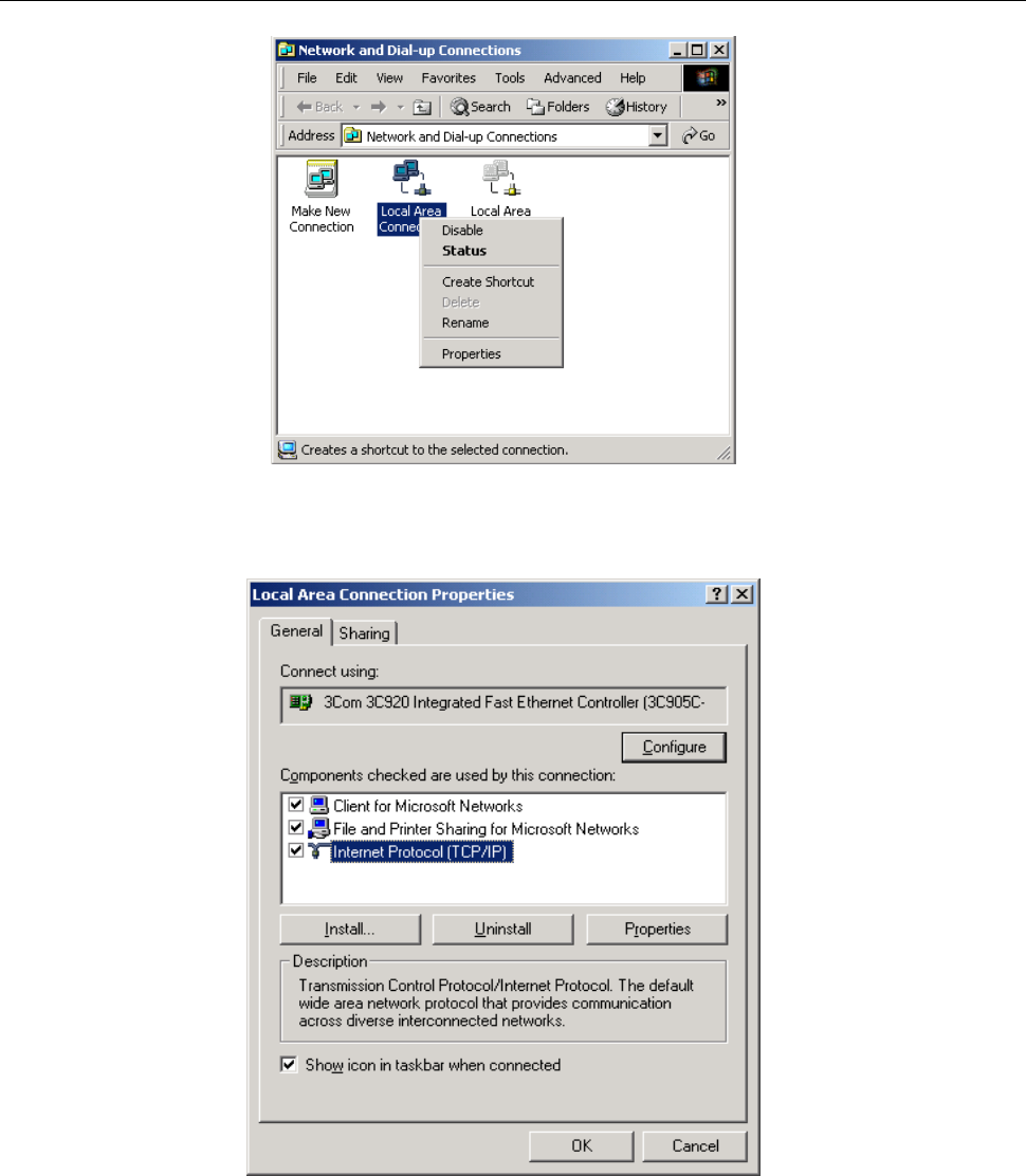
ADSL MODEM USER MANUAL
- 28 -
Figure C.1
2. The dialog box of networks is shown in Figure C.2. On the “General” property page select “Internet
Protocol(TCP/IP)”,and then click the “Properties” button.
Figure C.2
3. The “Internet Protocol (TCP/IP) properties” pop up window is shown as Figure C.3. Select “Use the
following IP address”. Input the following IP address: 192.168.1.11 and subnet mask: 255.255.255.0
(These addresses and subnet mask are similar with the factory default setting. The user can set different IP
addresse and subnet mask whenever necessary). Select “Gateway”, input the default IP address of the
gateway: 192.168.1.1 and IP address of Preferred DNS server: 202.96.209.133 (you can use your ISP’s
address), IP address of Alternate DNS server: 202.96.209.5(you can use your ISP’s address). The result is
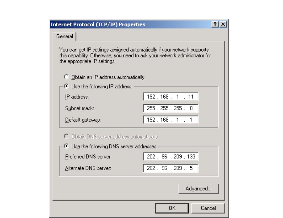
ADSL MODEM USER MANUAL
- 29 -
shown in Figure C.3.
Figure C.3
4. Click “OK” button to return to the “Local Area Connection Property” dialog box.
5. Click “OK” button to close the Network property dialog box.
APPENDIX D. SHIPPING LIST
Make sure the following items are included in the box. If any one of them is missing, please
contact the vendor immediately.
ADSL MODEM
×1
User Manual
×1
Telephone Line(RJ-11)
×2
Power Adapter
×1
Cable Cat5 RJ45
×1
Splitter
×1

ADSL MODEM USER MANUAL
- 30 -
FCC INFORMATION
FCC Caution
• Any changes or modifications not expressly approved by the party responsible for compliance could void the user's authority to
operate this equipment.
• This device complies with Part 15 of the FCC Rules. Operation is subject to the following two conditions: (1) This device may
not cause harmful interference, and (2) this device must accept any interference received, including interference that may cause
undesired operation.
• For product available in the USA market, only channel 1~11 can be operated. Selection of other channels is not possible.
• This device and its antenna(s) must not be co-located or operation in conjunction with any other antenna or transmitter..
THIS DEVICE MUST NOT BE CO-LOCATED OR OPERATING IN CONJUNCTION WITH ANY OTHER ANTENNA
OR TRANSMITTER
NOTE: THE MANUFACTURER IS NOT RESPONSIBLE FOR ANY RADIO OR TV INTERFERENCE CAUSED BY
UNAUTHORIZED MODIFICATIONS TO THIS EQUIPMENT. SUCH MODIFICATIONS COULD VOID THE USER’S
AUTHORITY TO OPERATE THE EQUIPMENT.
Federal Communications Commission (FCC) Requirements, Part 15
This equipment has been tested and found to comply with the limits for a class B digital device, pursuant to part 15 of the FCC
Rules. These limits are designed to provide reasonable protection against harmful interference in a residential installation.
This equipment generates, uses and can radiate radio frequency energy and, if not installed and used in accordance with the
instructions, may cause harmful interference to radio communications. However, there is no guarantee that interference will not
occur in a particular installation. If this equipment does cause harmful interference to radio or television reception, which can be
determined by turning the equipment off and on, the user is encouraged to try to correct the interference by one or more of the
following measures:
---Reorient or relocate the receiving antenna.
---Increase the separation between the equipment and receiver.
---Connect the equipment into an outlet on a circuit different from that to which the receiver is connected.
---Consult the dealer or an experienced radio/TV technician for help.
REGULATORY INFORMATION / DISCLAIMERS
Installation and use of this Wireless LAN device must be in strict accordance with the instructions included in the user
documentation provided with the product. Any changes or modifications (including the antennas) made to this device that are not
expressly approved by the manufacturer may void the user’s authority to operate the equipment. The manufacturer is not
responsible for any radio or television interference caused by unauthorized modification of this device, or the substitution of the
connecting cables and equipment other than manufacturer specified. It is the responsibility of the user to correct any interference
caused by such unauthorized modification, substitution or attachment. Manufacturer and its authorized resellers or distributors will
assume no liability for any damage or violation of government
CAUTION: To maintain compliance with FCC’s RF exposure guidelines, this equipment should be installed and operated
with minimum distance 20cm between the radiator and your body. Use on the supplied antenna. Unauthorized antenna,
modification, or attachments could damage the transmitter and may violate FCC regulations.
MPE Statement (Safety Information)
Your device contains a low power transmitter. When device is transmitted it sends out Radio Frequency (RF) signal.
FCC Information to User
This product does not contain any user serviceable components and is to be used with approved antennas only.
Any product changes or modifications will invalidate all applicable regulatory certifications and approvals.
SAFETY INFORMATION
In order to maintain compliance with the FCC RF exposure guidelines, this equipment should be installed and operated with
minimum distance 20cm between the radiator and your body. Use only with supplied antenna. Unauthorized antenna, modification,
or attachments could damage the transmitter and may violate FCC regulations.
Please use the factory recommended
power supply.