ADTRAN SR700A 802.11ac LTE/VDSL2 GATEWAY User Manual My
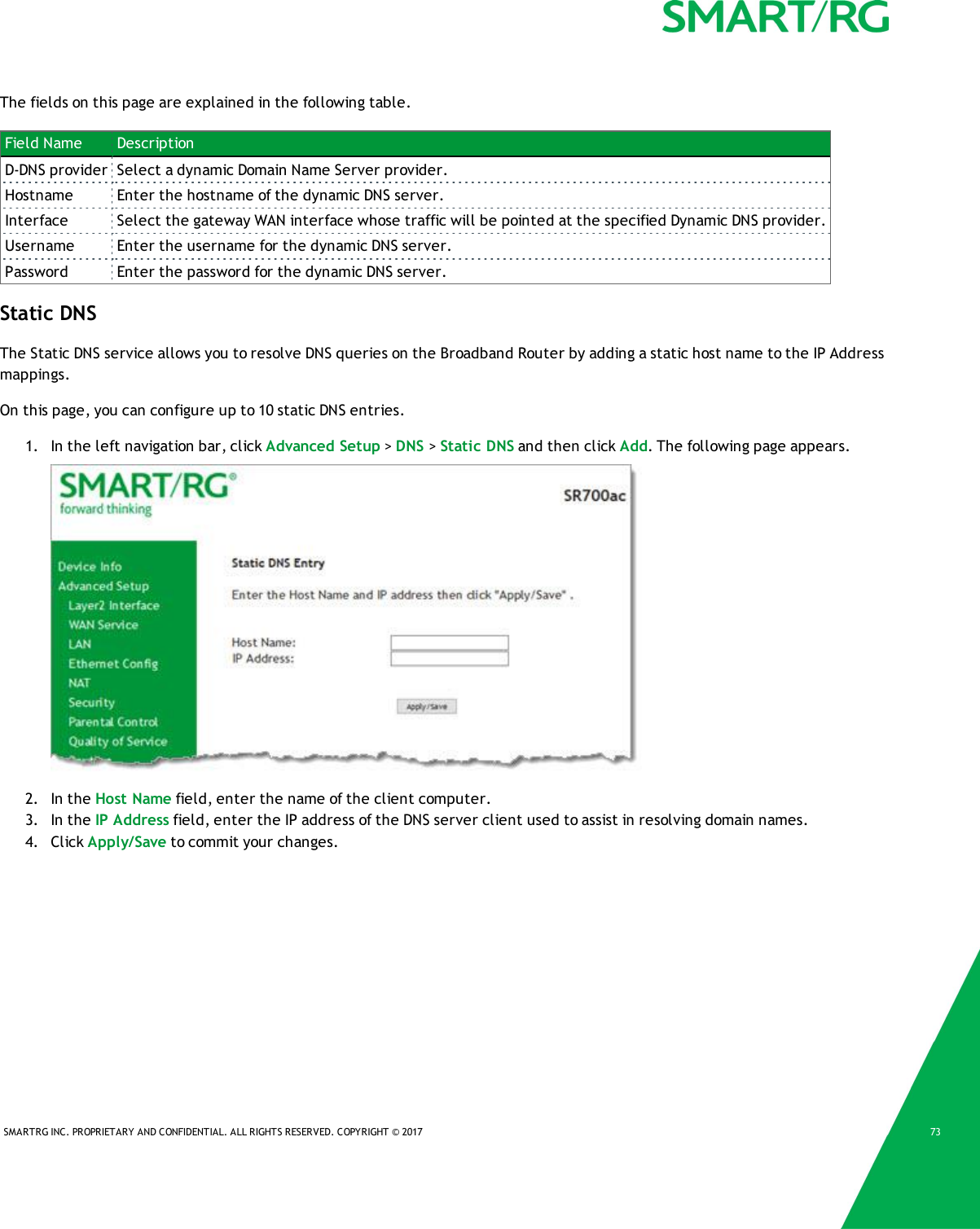
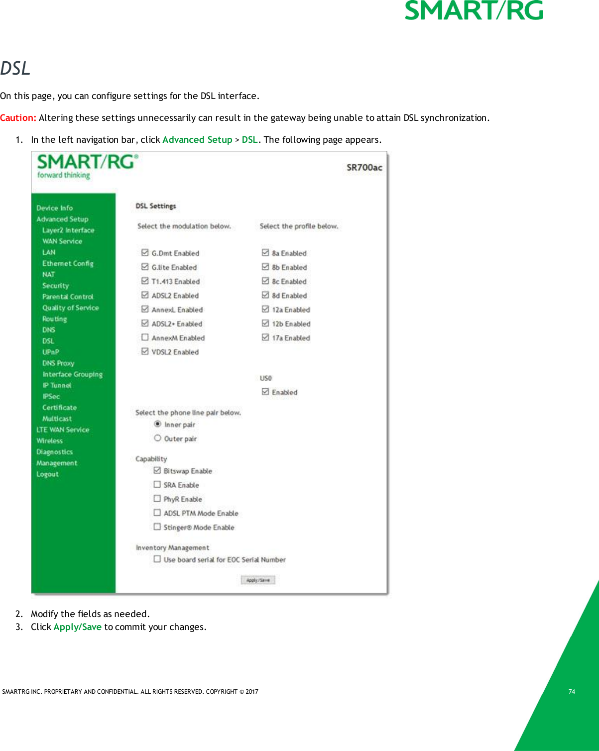
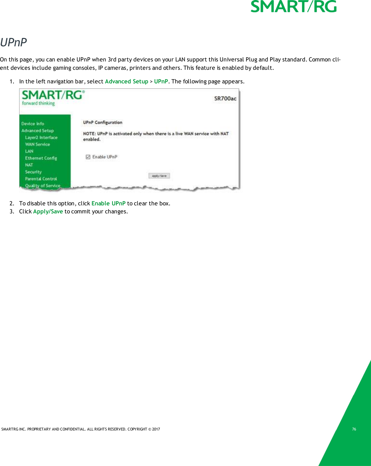
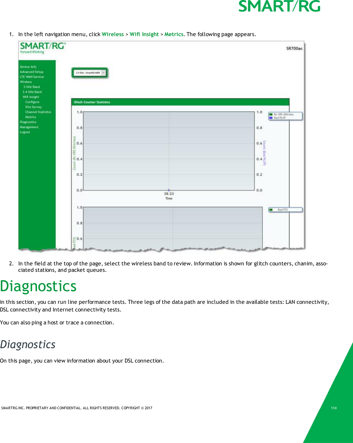
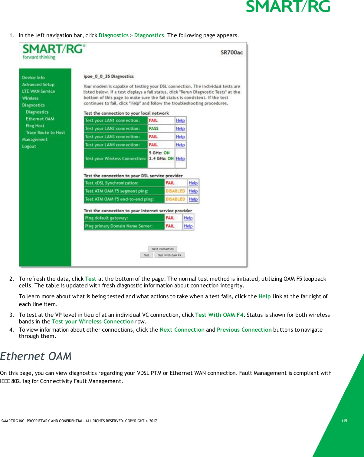
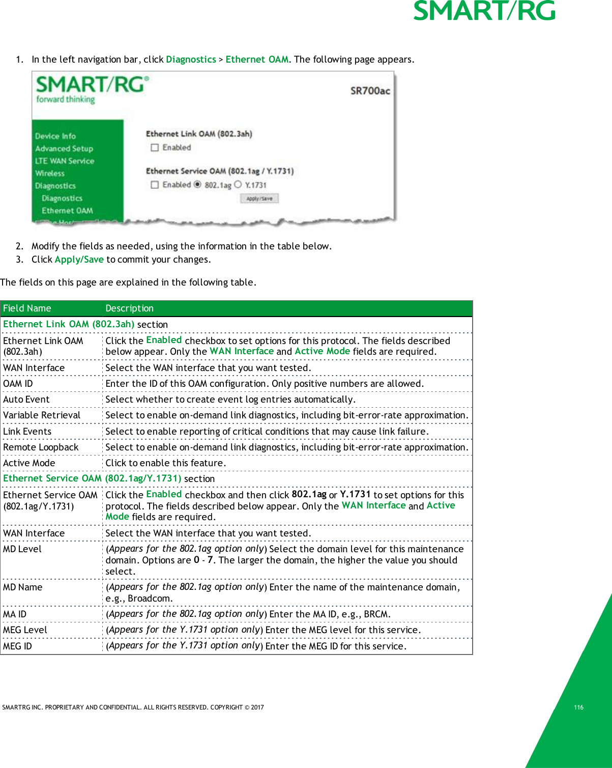
SmartRG, Inc. 802.11ac LTE/VDSL2 GATEWAY My
UserManual.wiki
>
ADTRAN
>
SR700A User Manual
User manual
Navigation menu
Upload a User Manual
Namespaces
Wiki Guide
HTML
PDF
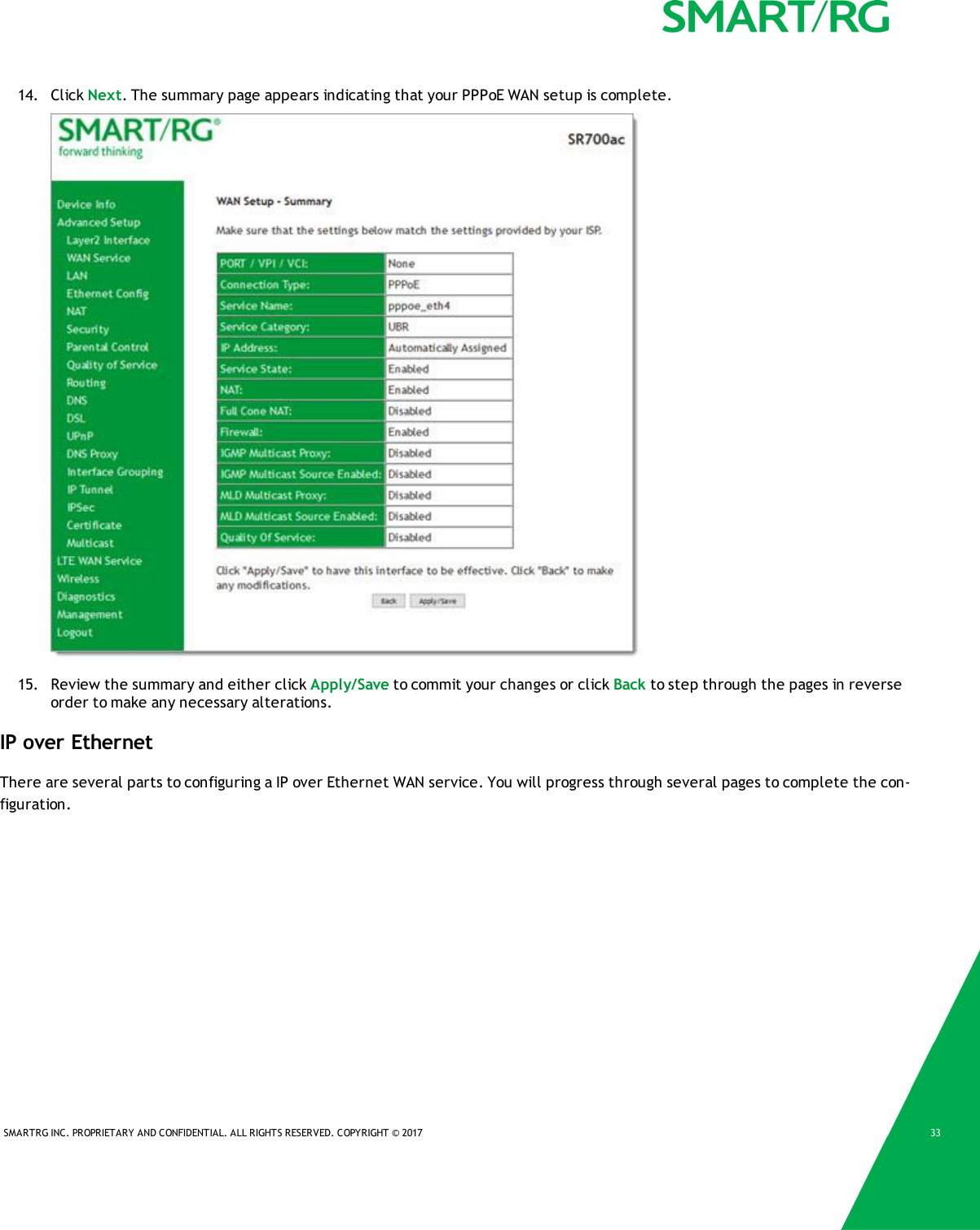
Info
Views
User Manual
Discussion / Help
Navigation

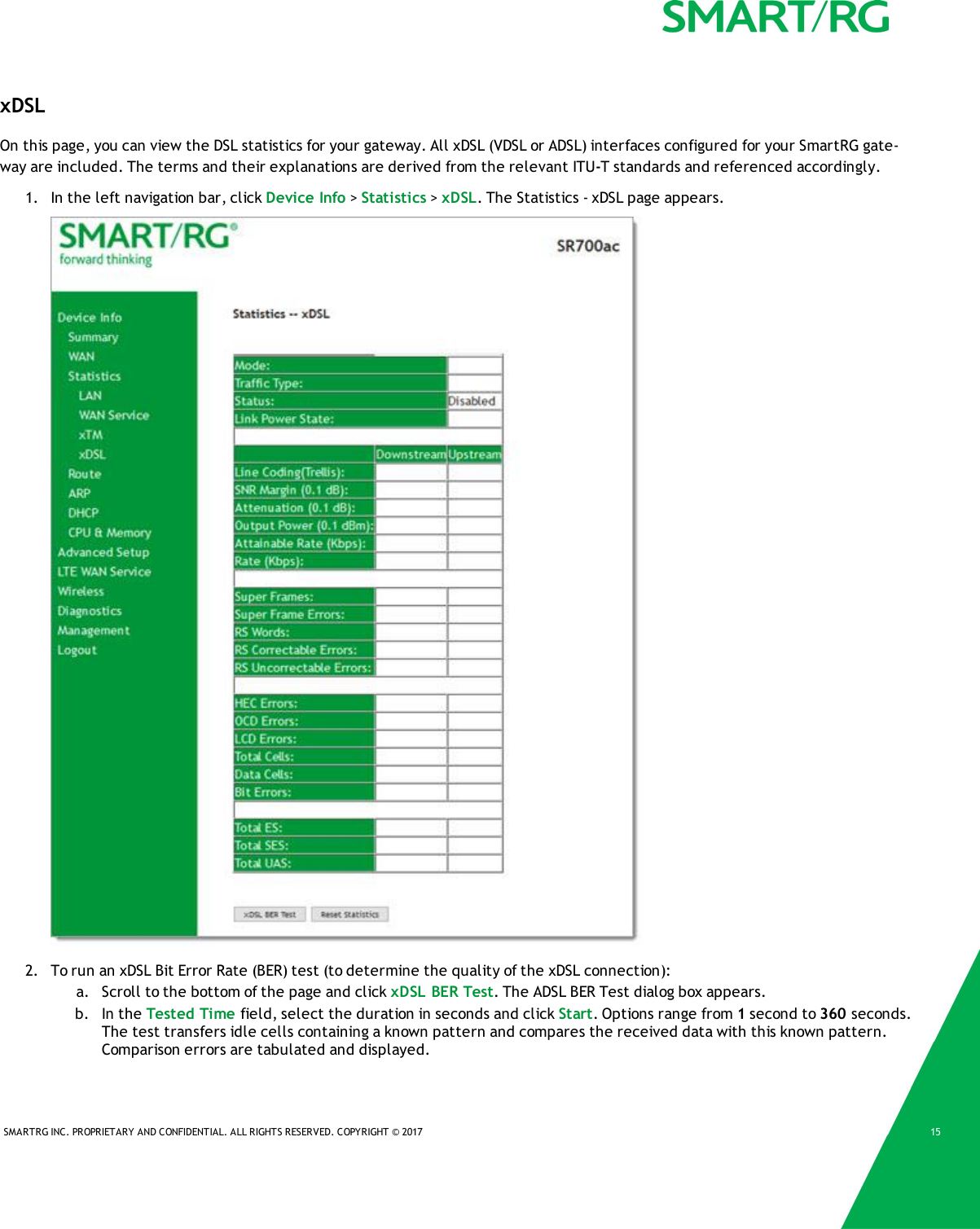
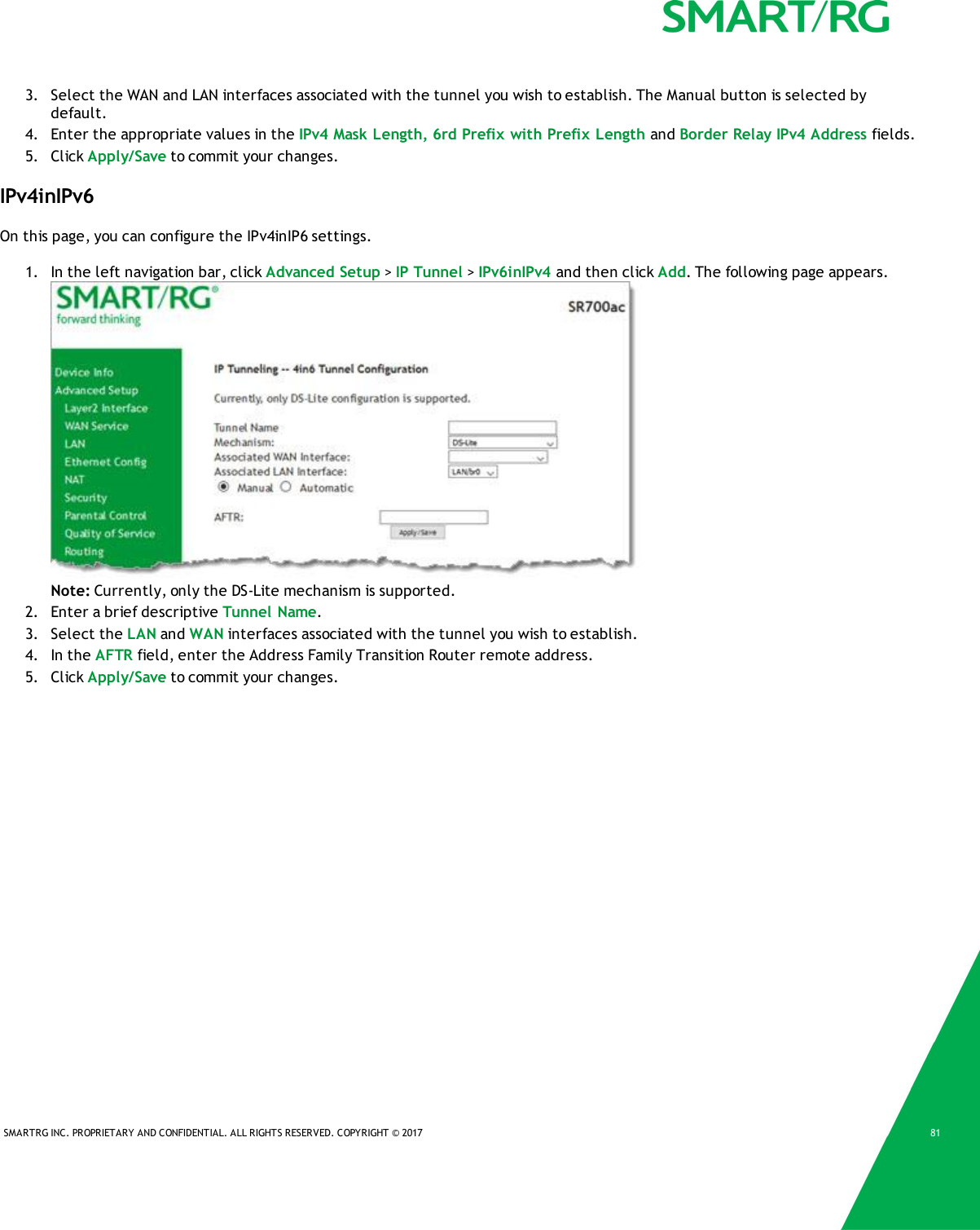
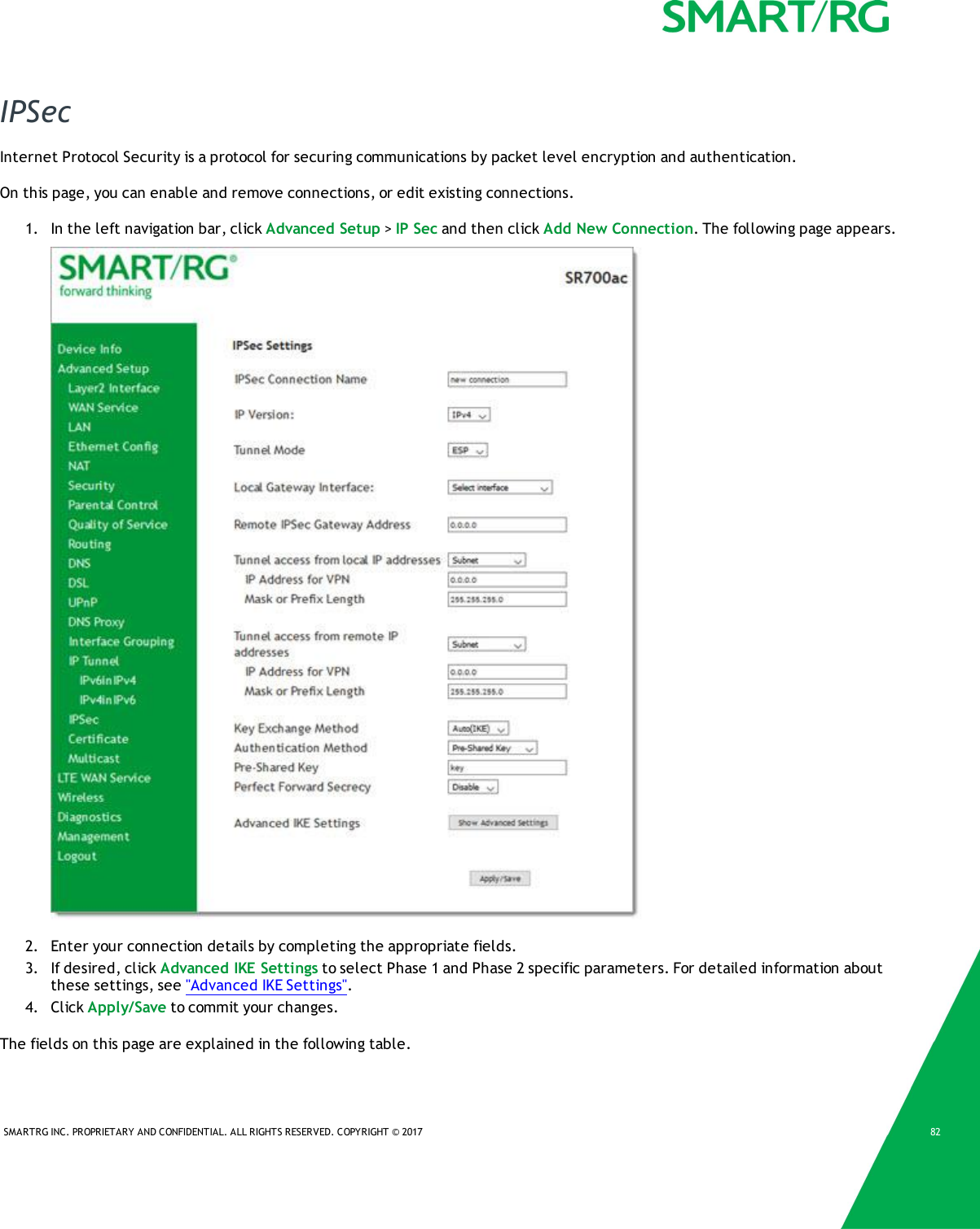
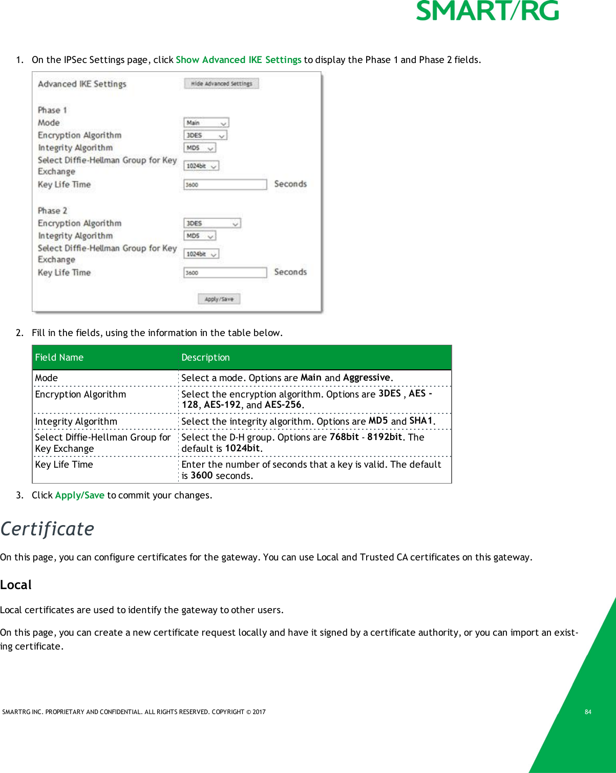
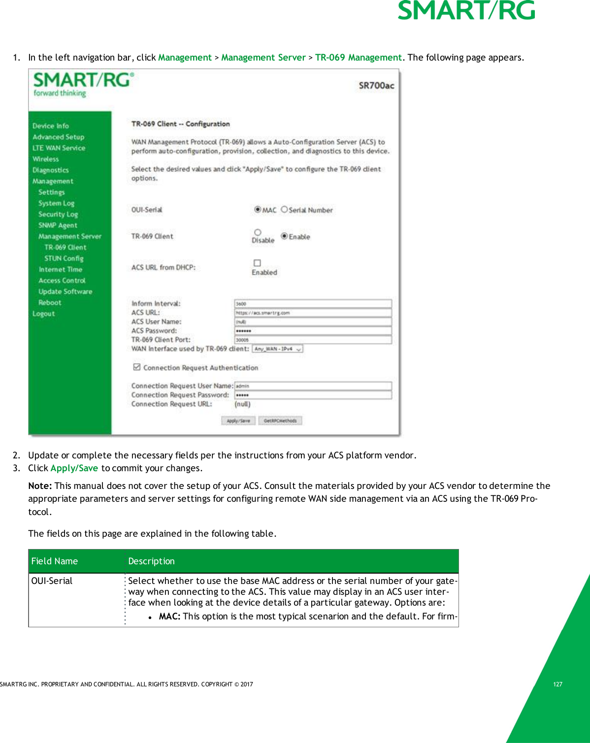
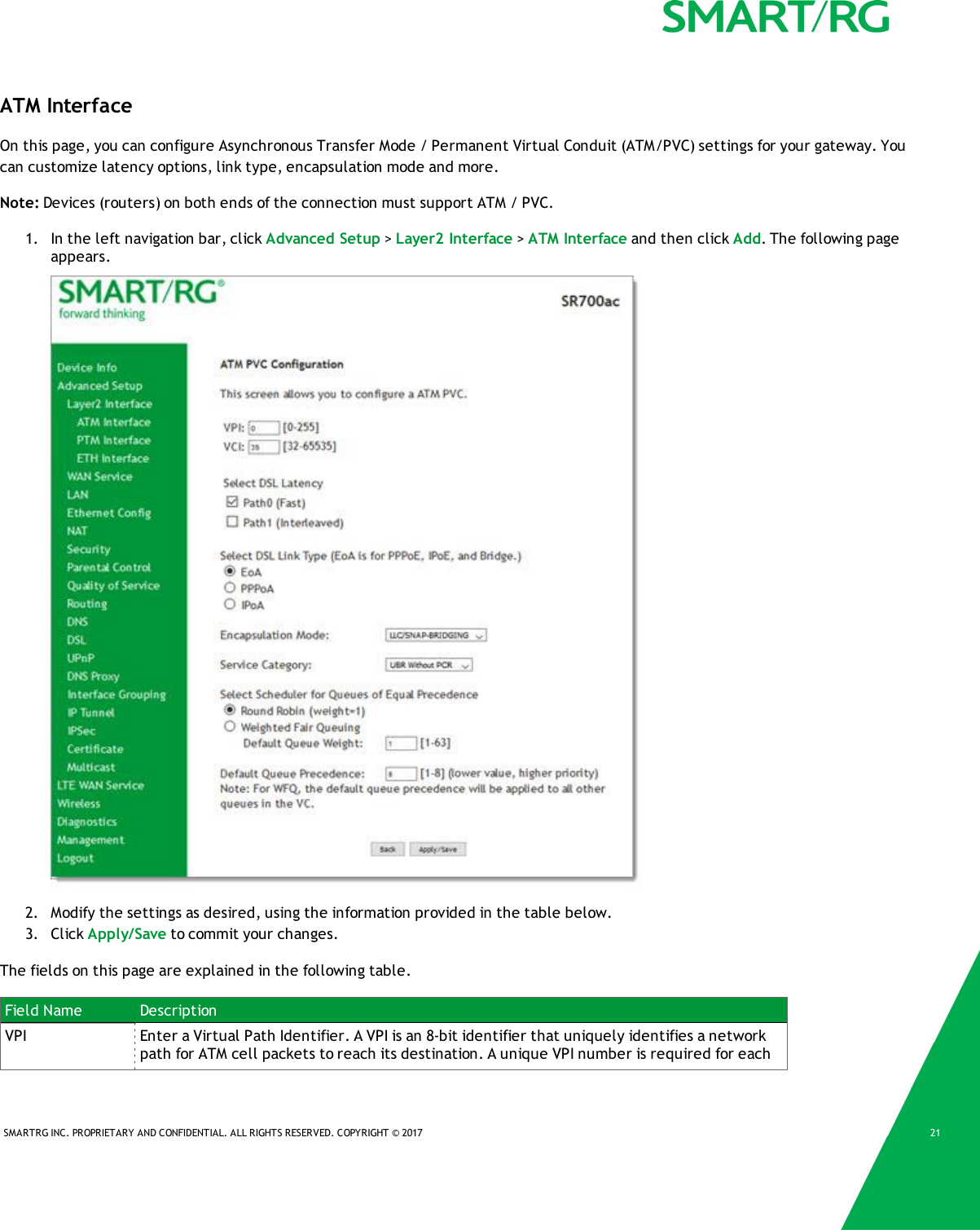
![SMARTRG INC. PROPRIETARY AND CONFIDENTIAL. ALL RIGHTS RESERVED. COPYRIGHT © 2017 163. To reset the counters, click Reset Statistics at the bottom of the page.The fields on this page are explained in the following table.Field Name DescriptionMode xDSL mode that the modem has trained under, such as ADSL2+, G.DMT, etc.Traffic Type Connection type. Options are: ATM,PTM and ETH.Status Status of the connection. Options are: Up,Disabled,NoSignal, and Initializing.Link Power State Current link power management state (e.g., L0, L2, L3).Downstream and Upstream columnsLine Coding (Trellis) State of theTrellis Coded Modulation. Options are On and Off.SNR Margin (0.1 db) The signal-to-noise ration margin (SNRM) is the maximum increase (in dB) of thereceived noise power, such that the modem can still meet all of the target BERsover all the frame bearers. [2]Attenuation (0.1 db) The signal attenuation is defined as the difference in dB between the powerreceived at the near-end and that transmitted from the far-end. [2]Output Power (0.1dBm)Transmit power from the gateway to the DSL loop relative to one Milliwatt (dBm).Attainable Rate (Kbps) The typically obtainable sync rate, i.e., the attainable net data rate that thereceive PMS-TC and PMD functions are designed to support under the following con-ditions:lSingle frame bearer and single latency operationlSignal-to-Noise Ratio Margin (SNRM) to be equal or above the SNR Target Mar-ginlBER not to exceed the highest BER configured for one (or more) latencypathslLatency not to exceed the highest latency configured for one (or more)latency pathslAccounting for all coding gains available (e.g., trellis coding, RS FEC) withlatency boundlAccounting for the loop characteristics at the instant of measurement [2]Rate (Kbps) The current net data rate of the xDSL link. Net data rate is defined as the sum of allframe bearer data rates over all latency paths. [2]Super Frames The number of xDSL Super Frames transmitted/received.Super Frame Errors The number of xDSL Super Frames transmitted/received with errors.RS Words The number of Reed-Solomon-based Forward Error Correction (FEC) codewords trans-mitted/received.RS Correctable Errors The number of Reed-Solomon-based FEC codewords received with errors that havebeen corrected.RS UncorrectableErrorsThe number of Reed-Solomon-based FEC codewords received with errors that werenot correctable.HEC Errors A count of ATM HEC errors detected. As per ITU-T G.992.1 and G.992.3, a1-byte HECis generated for each ATM cell header. Error detection is implemented as defined inITU-T I.432.1 with the exception that any HEC error shall be considered as a mul-](https://usermanual.wiki/ADTRAN/SR700A/User-Guide-3458765-Page-17.png)
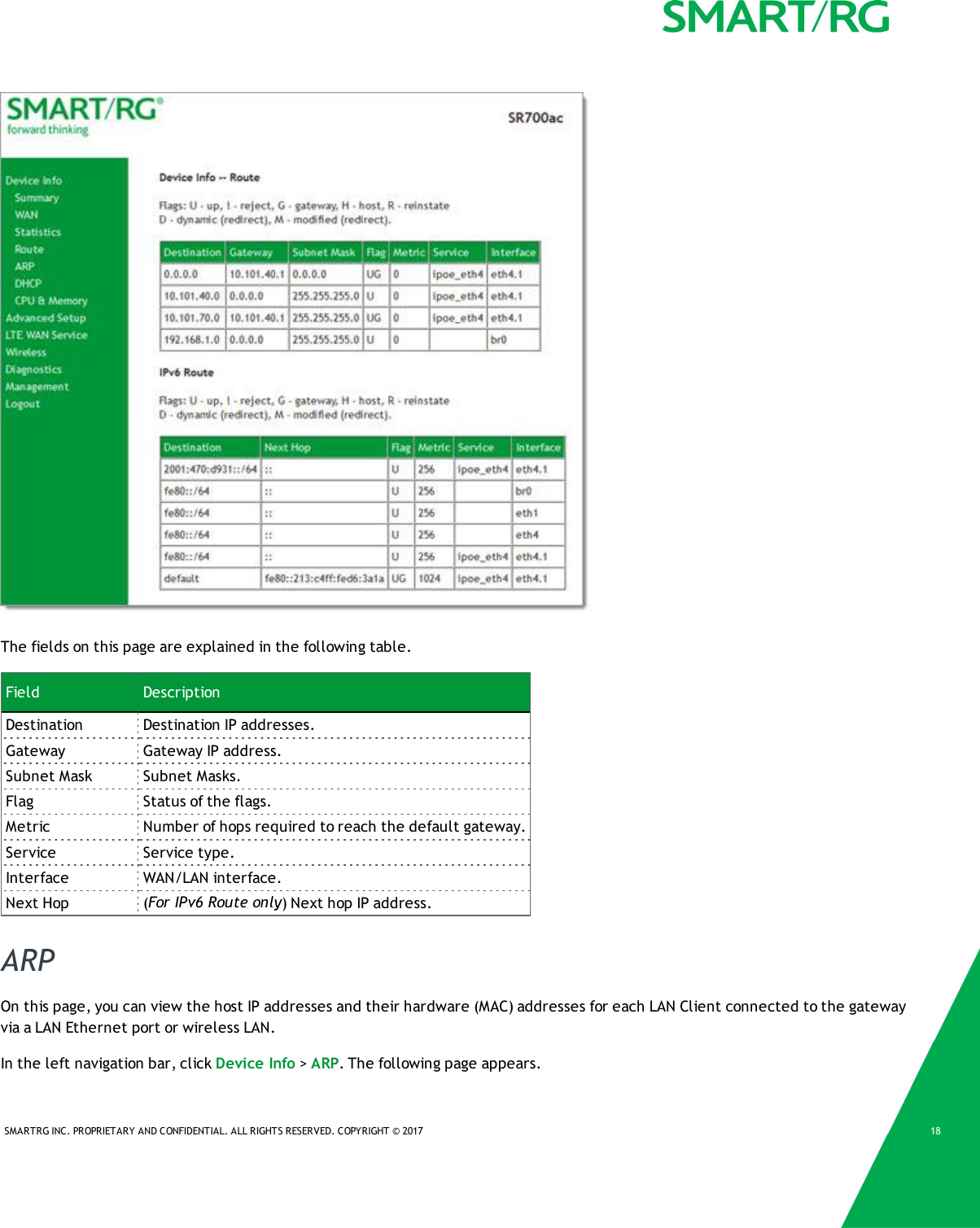
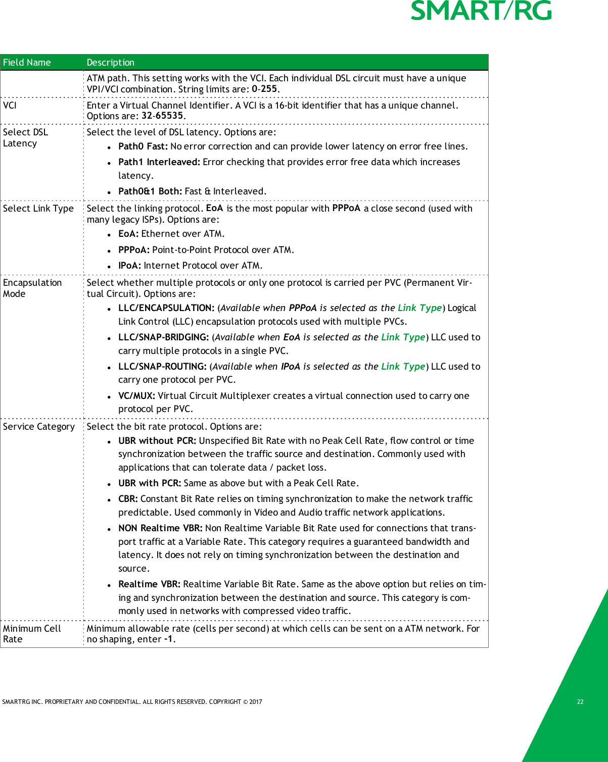
![SMARTRG INC. PROPRIETARY AND CONFIDENTIAL. ALL RIGHTS RESERVED. COPYRIGHT © 2017 17Field Name Descriptiontiple bit error, and therefore, HEC Error Correction is not performed. [1],[2]OCD Errors Total number of Out-of-Cell Delineation errors. ATM Cell delineation is the processwhich allows identification of the cell boundaries. The HEC field is used to achievecell delineation. [4] An OCD Error is counted when the cell delineation process trans-itions from the SYNC state to the HUNT state. [2]LCD Errors Total number of Loss of Cell Delineation errors. An LCD Error is counted when atleast one OCD error is present in each of four consecutive overhead channel periodsand SEF (Severely Errored Frame) defect is present. [2]Total Cells The total number of cells (OAM and Data cells) transmitted/received.Data Cells The total number of data cells transmitted/received.Bit Errors The total number of Idle Cell Bit Errors in the ATM Data Path. [3]Total ES Total number of Errored Seconds. This parameter is a count of 1-second intervalswith one or more CRC-8 anomalies. [4]Total SES Total number of Severely Errored Seconds. An SES is declared if, during a 1-secondinterval, there are 18 or more CRC-8 anomalies in one or more of the receivedbearer channels, or one or more LOS (Loss of Signal) defects, or one or more SEF(Severely Errored Frame) defects, or one or more LPR (Loss of Power) defects. [4]Total UAS Total number of Unavailable Seconds. This parameter is a count of 1-second inter-vals for which the xDSL line is unavailable. The xDSL line becomes unavailable atthe onset of 10 contiguous SESs. These 10 SES’s shall be included in the unavailabletime. Once unavailable, the xDSL line becomes available at the onset of 10 con-tiguous seconds with no SESs. These 10 seconds with no SES’s shall be excluded fromunavailable time. [4]References[1] ITU-T Recommendation G.992.1 (1999), Asymmetric digital subscriber line (ADSL) transceivers.[2] ITU-T Recommendation G.992.3 (2005), Asymmetric digital subscriber line transceivers 2 (ADSL2).[3] ITU-T Recommendation G.997.1 (2006), Physical layer management for digital subscriber line (DSL) transceivers.[4] ITU-T Recommendation I.432.1 (1999), B-ISDN user-network interface – Physical layer specification: General characteristics.RouteOn this page, you can view the LAN and WAN route table information configured in your SmartRG Gateway for both IPv4 and IPv6implementation.In the left navigation bar, click Device Info >Route. The following page appears.](https://usermanual.wiki/ADTRAN/SR700A/User-Guide-3458765-Page-18.png)
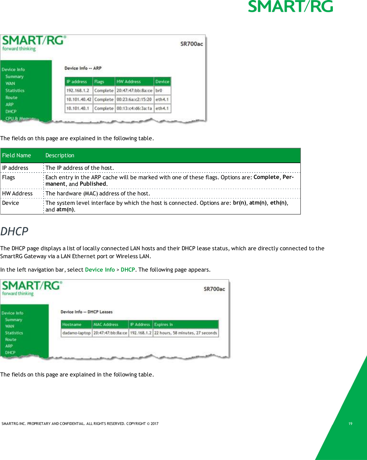
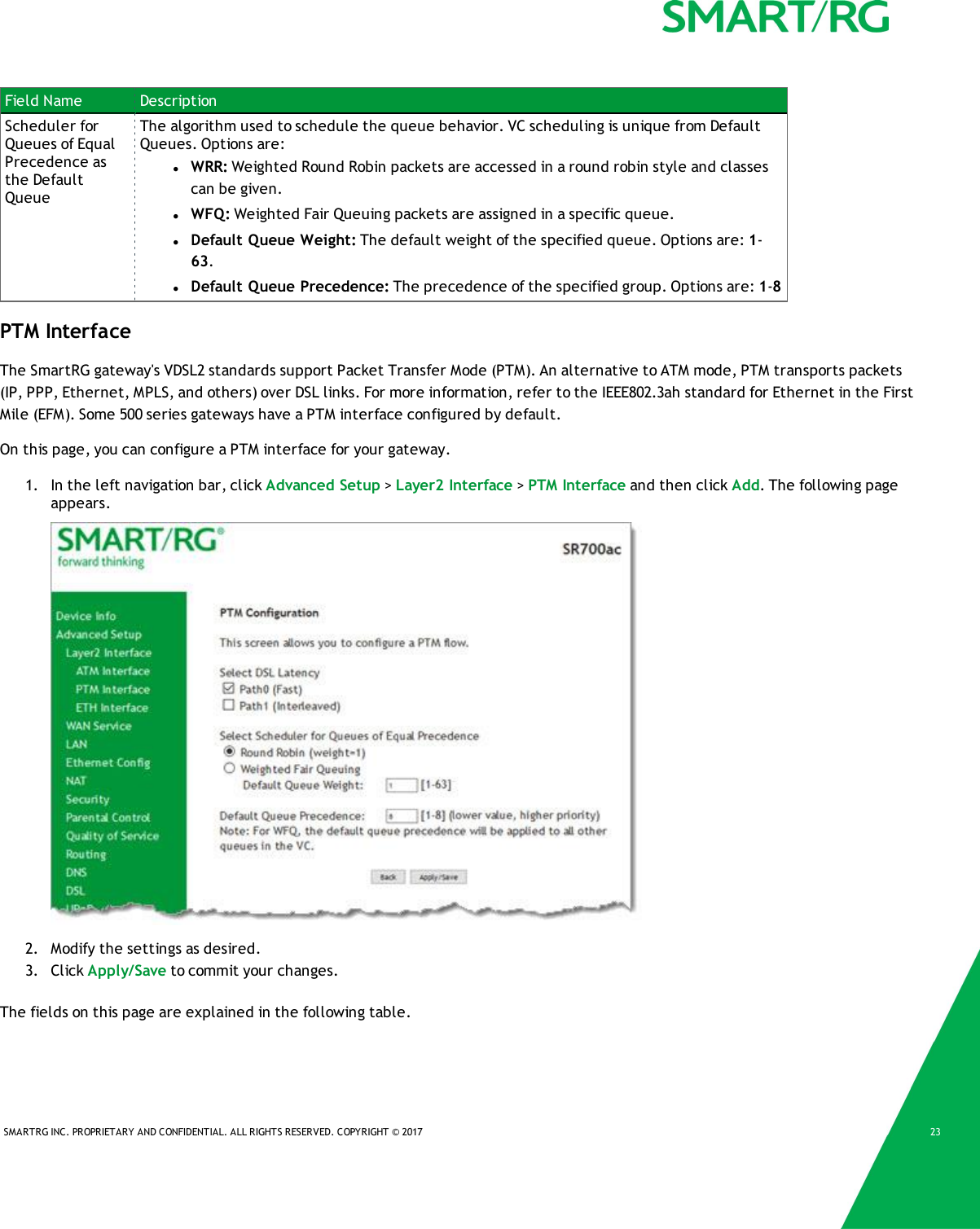
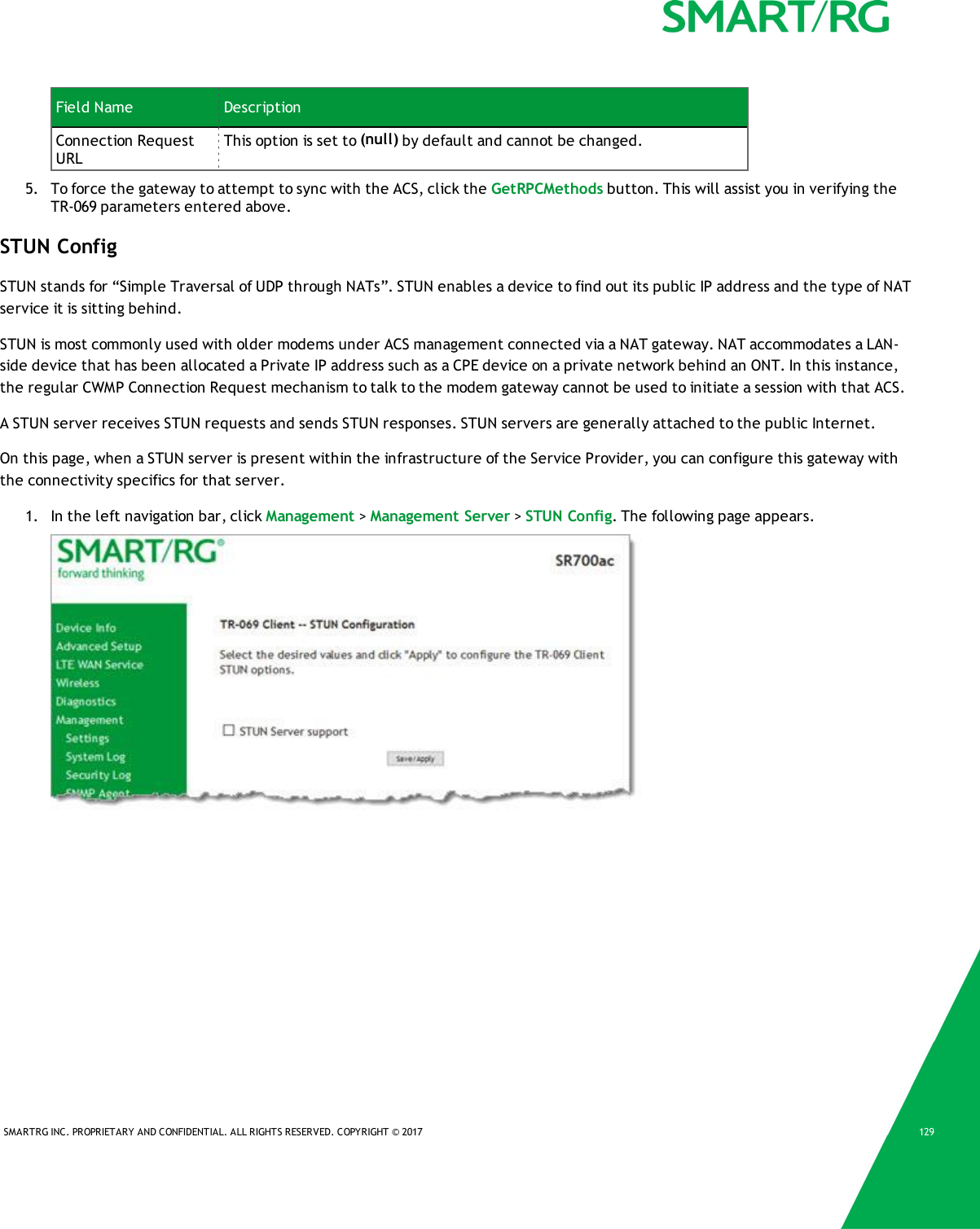
![SMARTRG INC. PROPRIETARY AND CONFIDENTIAL. ALL RIGHTS RESERVED. COPYRIGHT © 2017 53SecurityIn this section, you can configure filtering for IP and MAC.IP Filtering - OutgoingOn this page, you can add an outgoing filter when refusal of data from the LAN to the WAN is desired.1. In the left navigation bar, click Advanced Setup >Security and then click Add. The following page appears.2. Fill in the fields, using the information in the table below.3. Click Apply/Save to commit the completed entry.The fields on this page are explained in the following table.Field Name DescriptionFilter Name Enter a descriptive name for this filter. This is a free-form text field.IP Version For the filter to be configured and effective for IPV6 , the gateway must be installed on a net-work that is either a pure IPV6 network (with that protocol enabled) or is both IPV4 and IPV6dual protocol enabled/configured. Options are IPv4 and IPv6. The default is IPv4.If you select IPV6, both the Source and Destination IP address must be specified in IPV6 format.The following is an IPV6-compliant, hexadecimal address:2001:0DB8:AC10:FE01:0000:0000:0000:0001.Protocol Select the protocol profile for the filter you are defining. TCP/UDP is most commonly used.The options are TCP/UDP,TCP,UDP, and ICMP].](https://usermanual.wiki/ADTRAN/SR700A/User-Guide-3458765-Page-54.png)
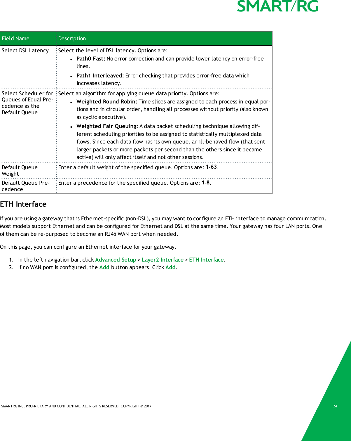
![SMARTRG INC. PROPRIETARY AND CONFIDENTIAL. ALL RIGHTS RESERVED. COPYRIGHT © 2017 54Field Name DescriptionSource IPaddress [/prefixlength]Enter the source IP address of a LAN side host for which you wish to filter/block outgoing trafficfor the specified protocol(s).Note: The address specified here can be a particular address or a block of IP addresses on agiven network subnet. This is done by appending the associated routing "/prefix" lengthdecimal value (preceded with the slash) to the addresses. A valid decimal routing prefix isrequired for defining the subnet mask per CIDR notation.Source Port (portor port:port)Set the outgoing host port (or range of ports) for the above host (or range of hosts defined byoptional routing or "/prefix" subnet mask) to define the ports profile for which egress trafficwill be filtered from reaching the specified destination(s).Destination IPaddressEnter the destination IP address of a LAN side host for which you wish to filter/block outgoingtraffic for the specified protocol(s).Note: The address specified here can be a particular address or a block of IP address on a givennetwork subnet. This is done through appending the address with the routing " /prefix " lengthdecimal value (preceded with the slash) associated. A valid decimal routing prefix is requiredfor defining the subnet mask per CIDR notation.estination Port(port or port:-port)Set the destination host port (or range of ports) for the above host (or range of hosts) to definethe destination port profile for which the filtered host egress traffic will be filtered from reach-ing the otherwise intended destination(s), e.g., to block the traffic to those ports on, say, acomputer external to the local network.IP Filtering - IncomingOn this page, you can add an incoming filter when refusal of data from the WAN to the LAN is desired.Note: This option is not available in the SR515ac model.1. In the left navigation bar, click Advanced Setup >Security >IP Filtering >Incoming and then click Add. The following pageappears.](https://usermanual.wiki/ADTRAN/SR700A/User-Guide-3458765-Page-55.png)
![SMARTRG INC. PROPRIETARY AND CONFIDENTIAL. ALL RIGHTS RESERVED. COPYRIGHT © 2017 552. Fill in the fields, using the information in the table below.3. Click Apply/Save to commit your changes.The fields on this page are explained in the following table.Field Name DescriptionFilter Name A free-form text field. Enter a descriptive name for this filter.IP Version Select the IP version for this filter. Options are IPv4 and IPv6. The default isIPv4.Protocol Select the protocol to be associated with this incoming filter. Options are:TCP/UDP,TCP,UDP, or ICMP.Source IP address [/pre-fix length]Enter the source IP address for rule. For IPv6, enter the prefix as well.Source Port (port orport:port)Enter source port number or range (xxxxx:yyyyy).Destination IP address[/prefix length]Enter the destination IP address for rule. For IPv6, enter the prefix as well.Destination Port (port orport:port)Enter destination port number or range (xxxxx:yyyyy).WAN Interfaces Select the WAN interfaces to which this rule will be applied. Options are SelectAll or the interfaces defined for your network. The default is Select All.](https://usermanual.wiki/ADTRAN/SR700A/User-Guide-3458765-Page-56.png)