ADTRAN SR700A 802.11ac LTE/VDSL2 GATEWAY User Manual My
SmartRG, Inc. 802.11ac LTE/VDSL2 GATEWAY My
ADTRAN >
User manual

/ Gateway User Manual
Model: SR700ac
Release 1.0 March 2017
501 SE Columbia Shores Boulevard, Suite 500
Vancouver, Washington 98661 USA
+1 360 859 1780 / smartrg.com

Table of Contents
Welcome! 3
Purpose & Scope 3
Intended Audience 3
Getting Assistance 3
Copyright and Trademarks 3
Disclaimer 4
Getting Familiar with your Gateway 5
LED Status Indicators 5
Connections 6
DSL 6
WAN 6
LAN 7
USB 7
POWER 7
External Buttons 7
WPS Button 7
WiFi or WLAN Button 8
Reset Button 8
Installing your SR700ac Gateway 8
Logging into your Gateway's UI 8
Device Info 10
Summary 10
WAN 11
Statistics 12
LAN 12
WAN Service 13
xTM 13
xDSL 15
References 17
Route 17
ARP 18
DHCP 19
CPU & Memory 20
Advanced Setup 20
Layer2 Interface 20
ATM Interface 21
PTM Interface 23
ETH Interface 24
WAN Service 26
xPPP over Ethernet 26
IP over Ethernet 33
Bridging 39
LAN 43
IPv6 Autoconfig 45
Ethernet Config 47
NAT 49
Virtual Servers 49
Port Triggering 51
DMZ Host 52
Security 53
IP Filtering - Outgoing 53
IP Filtering - Incoming 54
MAC Filtering 56
Add a MAC Filtering Rule 57
Parental Control 57
Time Restriction 58
URL Filter 59
Quality Of Service 59
QoS Config 60
Supported DSCP Values 61
QoS Queue Config 61
WLAN Queue 63
QoS Classification 63
QoS Port Shaping 66
Routing 67
Default Gateway 67
Static Route 67
Policy Routing 68
RIP (Routing Information Protocol) 69
DNS 71
DNS Server 71
Dynamic DNS 72
Static DNS 73
DSL 74
UPnP 76
DNS Proxy 77
Interface Grouping 78
80
IP Tunnel 80
IPv6inIPv4 80
IPv4inIPv6 81
IPSec 82
Advanced IKE Settings 83
Certificate 84
Local 84
Trusted CA 86
Multicast 88
LTE WAN Service 91
Status Information 91
Network Settings 92
Wireless 93
Basic 93
Security 95
Open & Shared Authentication 97
802.1X Authentication 98
WPA2 & Mixed WPA2/WPA Authentication 100
WPA2-PSK & Mixed WPA2/WPA-PSK Authentic-
ation 101
MAC Filter 102
Wireless Bridge 103
Advanced 104
Station Info 108
Wifi Insight 109
Site Survey 111
Channel Statistics 112
Metrics 113
Diagnostics 114
Diagnostics 114
Ethernet OAM 115
Ping Host 117
Trace Route to Host 118
Management 118
Settings 118
Backup 118
Update 120
Restore Default 121
SMARTRG INC. PROPRIETARY AND CONFIDENTIAL. ALL RIGHTS RESERVED. COPYRIGHT © 2016 1

Table of Contents
System Log 122
Security Log 124
SNMP Agent 125
Management Server 126
TR-069 Client 126
STUN Config 129
Internet Time 131
Access Control 132
Accounts 133
Add an Account 133
Modify or Delete an Account 134
Default Passwords 136
Services 136
Passwords 137
Access List 138
Logout Timer 139
Update Software 140
Reboot 140
Logging Out 141
Appendix: Compliance Statements 141
FCC Interference Statement 141
FCC Radiation Exposure Statement 142
FCC - PART 68 142
Ringer Equivalency Number Statement 142
IC CS-03 statement 143
Canada Statement 143
5GHz 144
Revision History 144
SMARTRG INC. PROPRIETARY AND CONFIDENTIAL. ALL RIGHTS RESERVED. COPYRIGHT © 2016 2

SMARTRG INC. PROPRIETARY AND CONFIDENTIAL. ALL RIGHTS RESERVED. COPYRIGHT © 2017 3
Welcome!
Thank you for purchasing this SmartRG product.
SmartRG offers solutions that simplify the complex Internet ecosystem. Our solutions include hardware, software, applications,
enhanced network insights, and security delivered via a future-proof operating system. Based in the USA, SmartRG provides local,
proactive software development and customer support. We proudly offer the best, most innovative broadband gateways available.
Learn more at www.SmartRG.com.
Purpose & Scope
This Gateway User Manual provides SmartRG customers with installation, configuration and monitoring information for their SR700ac
gateway.
Intended Audience
The information in this document is intended for Network Architects, NOC Administrators, Field Service Technicians and other net-
working professionals responsible for deploying and managing broadband access networks. Readers of this manual are assumed to
have a basic understanding of computer operating systems, networking concepts and telecommunications.
Getting Assistance
Frequently asked questions are provided at the bottom of the Subscribers page of the SmartRG Web site.
Subscribers: If you require further help with this product, please contact your service provider.
Service providers: if you require further help with this product, please open a support request.
Copyright and Trademarks
Copyright © 2017 by SmartRG, Inc. Published by SmartRG, Inc. All rights reserved.
The contents of this publication may not be reproduced in any part or as a whole, transcribed, stored in a retrieval system, trans-
lated into any language, or transmitted in any form or by any means, electronic, mechanical, magnetic, optical, chemical, pho-
tocopying, manual, or otherwise, without the prior written permission of SmartRG, Inc.

SMARTRG INC. PROPRIETARY AND CONFIDENTIAL. ALL RIGHTS RESERVED. COPYRIGHT © 2017 4
Disclaimer
SmartRG does not assume any liability arising out of the application or use of any products, or software described herein. Neither
does it convey any license under its patent rights nor patent rights of others. SmartRG further reserves the right to make changes to
any products described herein without notice. This publication is subject to change without notice.
Any trademarks mentioned in this publication are used for identification purposes only and may be properties of their respective
owners.
SMARTRG INC. PROPRIETARY AND CONFIDENTIAL. ALL RIGHTS RESERVED. COPYRIGHT © 2017 5
Getting Familiar with your Gateway
This section contains a quick description of the Gateway's lights, ports, and buttons. SmartRG produces several models that vary
slightly in capabilities (See Appendix B for details) but the basic scheme of lights, ports and buttons represented in this section
exists on each model.
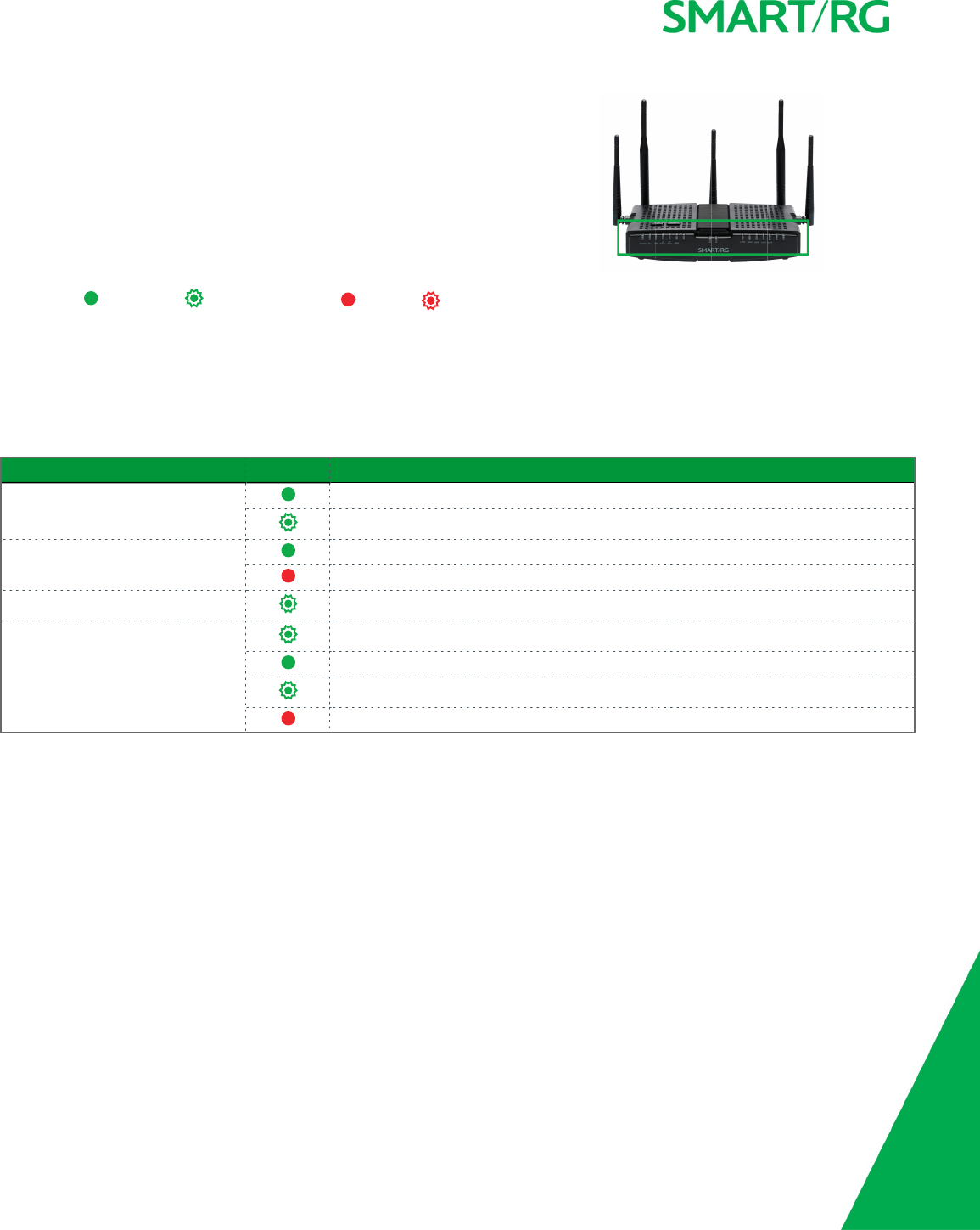
LED Status Indicators
Your SmartRG gateway has several indicator lights (LEDs) on its exterior. The fol-
lowing table explains the actions of the LEDs located on the front of the SR700ac
gateway.
Legend: Green Green blinking Red Red blinking
LED Action Explanation
All LEDs except those listed below Connection enabled.
Data being transferred.
POWER DSL sync acquired and device online.
Power up test.
DSL DSL sync in progress.
WPS WPS setup procedure in progress.
WPS connection completed.
Session overlap detected. Possible security risk.
Failed to find any partner with which to pair.
SMARTRG INC. PROPRIETARY AND CONFIDENTIAL. ALL RIGHTS RESERVED. COPYRIGHT © 2017 6
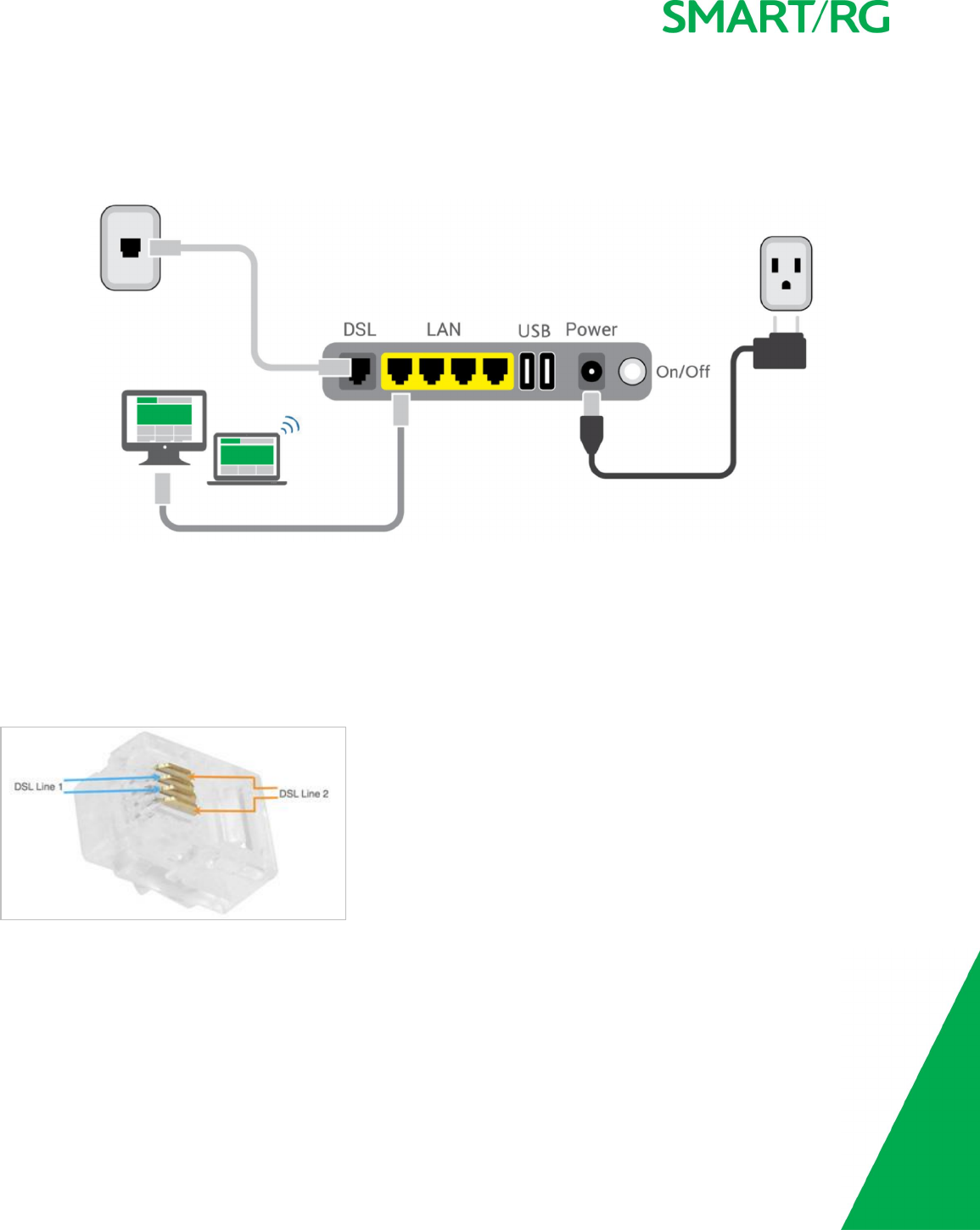
Connections
Below is a generic representation of a SmartRG gateway, Your specific model may have more or fewer ports and controls. Refer to
the Quick Start Guide enclosed with your gateway for specifics regarding installation of your particular model.
The ports depicted in this example are described below.
DSL
The grey RJ12 port labeled DSL is specifically intended for connection to an internet provider via a DSL (Digital Subscriber Line) ser-
vice. The center pair carries the first DSL line. For models like the SR550n equipped with two DSL ports and bonded DSL capability,
the outer pair carries the second line.
WAN
A stand-alone RJ45 port labeled WAN enables your SmartRG gateway to be hard-wired to another network device with a RJ45/Eth-
ernet output such as a cable, fiber, or DSL modem.

SMARTRG INC. PROPRIETARY AND CONFIDENTIAL. ALL RIGHTS RESERVED. COPYRIGHT © 2017 7
For models with a stand-alone, RJ45, WAN port and a DSL port, the WAN port can be re-purposed to function as an additional LAN
port when your internet connection is via DSL.
For instructions to enable this SmartPortTM feature, see the Ethernet Configuration section in this manual.
LAN
The four (yellow) RJ45 ports across the back of your gateway labeled LAN1, LAN2, LAN3, LAN4 are the means to connect client
devices such as computers and printers to your gateway.
On some models, one of these four ports may be labeled as WAN indicating SmartPortTM support. SmartPort allows a LAN port to be
re-purposed to function as an Ethernet WAN port (described above). When this port is serving as a LAN port, the corresponding LED
on the face of the unit is labeled "WAN"
For instructions to enable this SmartPortTM feature, see the Ethernet Configuration section in this manual.
USB
USB ports on SmartRG products currently provide +5 DC volts.
POWER
Use only the power supply included with your gateway. Intended for indoor use only.
External Buttons
SmartRG gateways provide push-button controls on the exterior for critical features. These buttons provide a convenient way to trig-
ger WPS mode, toggle the WiFi radio on and off, or reset the gateway. Their presence and locations vary by model.
WPS Button
The WPS button triggers WPS (Wi-Fi Protected Setup™) mode. WPS is a standard means for creating a secure connection between
your gateway and various wireless client devices. It is designed to simplify the pairing process between devices.
This button is located on the top of the gateway. If you have client devices that support WPS, use this button to automatically con-
figure wireless security for your network.
WPS configures one client device at a time. You can repeat the steps as necessary for each additional WPS-compliant device you
wish to connect.
For specific instructions, refer to the Quick Start Guide included with your gateway. Also see the "Basic" section of this manual.

SMARTRG INC. PROPRIETARY AND CONFIDENTIAL. ALL RIGHTS RESERVED. COPYRIGHT © 2017 8
WiFi or WLAN Button
The button labeled WiFi or WLAN (depending on model) toggles the WiFi radio on and off. The WLAN LED indicator on the gateway dis-
plays the current state of the Wi-Fi radio. This button is located on the top of the gateway.
To activate the Wi-Fi radio, press and hold the WiFi (WLAN) button for 3-5 seconds and then release. Expect a 1-3 second delay
before the WiFi (WLAN) LED turns on. Repeat this step to deactivate the Wi-Fi radio.
Reset Button
The Reset button is a small hole in the gateway's enclosure with the actual button mounted behind the surface. This style of push-
button prevents the gateway from being inadvertently reset during handling. Reset must be actuated with a paper clip or similar
implement. This button is located on the back of the gateway.
This pin-hole sized reset button has three functions. The duration for which the button is held dictates which function is carried
out.
!!!ASKSME: Are the hold durations correct?
Hold Duration Effect
Less than 6
seconds
Performs a modem reset that is equivalent to the Reboot function in the gateway software.
6-20 seconds Performs the software equivalent to the Restore Defaults function in the gateway software.
20 or more seconds Changes the POWER LED to red and the gateway enters CFE mode which is a state associated with performing
firmware updates via Internet browser.
Installing your SR700ac Gateway
1. Connect one end of the phone cable to the DSL port on the gateway and connect the other end to the phone jack on the
wall installed by your provider.
2. Connect one end of the Ethernet cable to a LAN port on the gateway and connect the other end to your computer.
3. Plug the power adapter to the wall outlet and then connect the other end of it to the Power port of the gateway. Turn on
the unit by pressing the On/Off button on the back of the gateway.
Your gateway is now automatically being set up to connect to the Internet. This process may take a few minutes to complete before
you can begin using your Internet applications (browser, email, etc.). If you are unable to connect to the Internet, verify that all
cable connections are in place and the gateway’s power is turned on.
Logging into your Gateway's UI
To manually configure the SmartRG Gateway, you must access the gateway's embedded web UI.
1. Open a browser and enter the gateway's default address (usually http://192.168.1.1; may also be http://192.168.0.1) in the
address bar.
2. For some models, the Network status page appears. If so, click the Manage gateway (advanced) link (usually located in the
upper right corner). The Authentication Required dialog box appears.
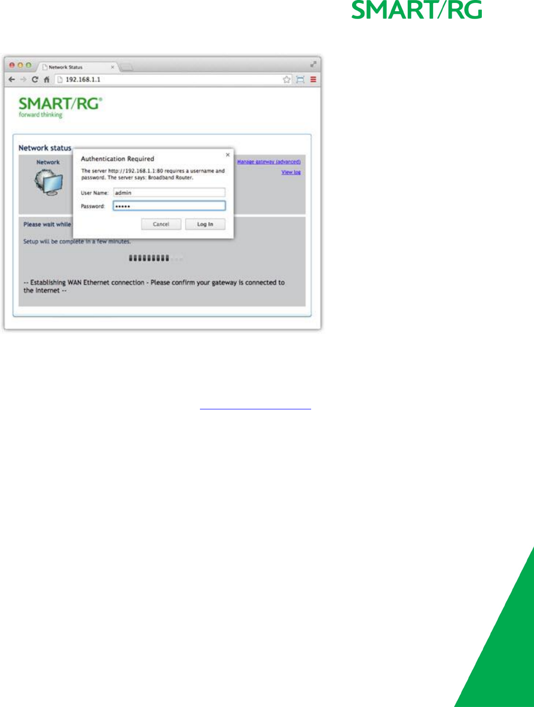
SMARTRG INC. PROPRIETARY AND CONFIDENTIAL. ALL RIGHTS RESERVED. COPYRIGHT © 2017 9
3. For all models, enter the default username and password (usually admin/admin) and click Login or OK to display the default
landing page. For many models, this is the Device Info page.
Note: The gateway's UI can be accessed via the WAN connection by entering the WAN IP address in your browser's address bar and
entering the default username and password: support/support. WAN HTTP access control MUST be enabled to access the gateway's
UI via the WAN connection. For more information, see the Management Access Control section.
If your SmartRG gateway is configured for "bridge mode" (modem) operation, your PC will NOT be able to acquire an address via CPE
DHCP. Instead, manually configure your PC's interface with an IP address on the default network (e.g., 192.168.1.100).
The remainder of this guide is dedicated to a sequential walk-through of the gateway user interface. Screen captures are provided
along with descriptions of the options available on the pictured page. Where applicable, valid values are provided.
For in-depth "how-to" information for specific scenarios, go to the knowledge base found on our support web site. Access to this site is
restricted to SmartRG customers and partners. Do not share links to this site with your subscribers.
SMARTRG INC. PROPRIETARY AND CONFIDENTIAL. ALL RIGHTS RESERVED. COPYRIGHT © 2017 10
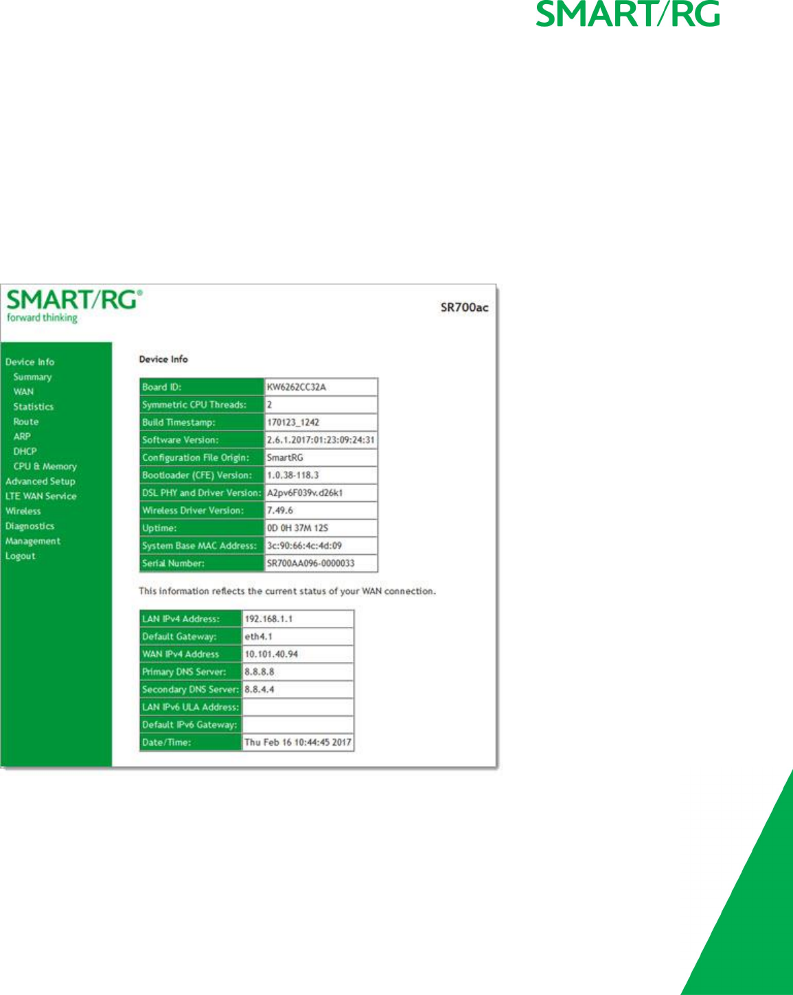
Device Info
There are several selections under Device Info in the left navigation bar. Each of them shows a different element of the gateway's
setup, status or nature of its connection with the provider and also with LAN devices. Device Info pages are read-only. You cannot
interact with or change the settings in this section.
Summary
When you log into the gateway interface, the Device Info summary page is the first to appear. This page displays details about the
hardware and software associated with your gateway. In addition, the current status of the WAN connection (if present) is shown.
SMARTRG INC. PROPRIETARY AND CONFIDENTIAL. ALL RIGHTS RESERVED. COPYRIGHT © 2017 11
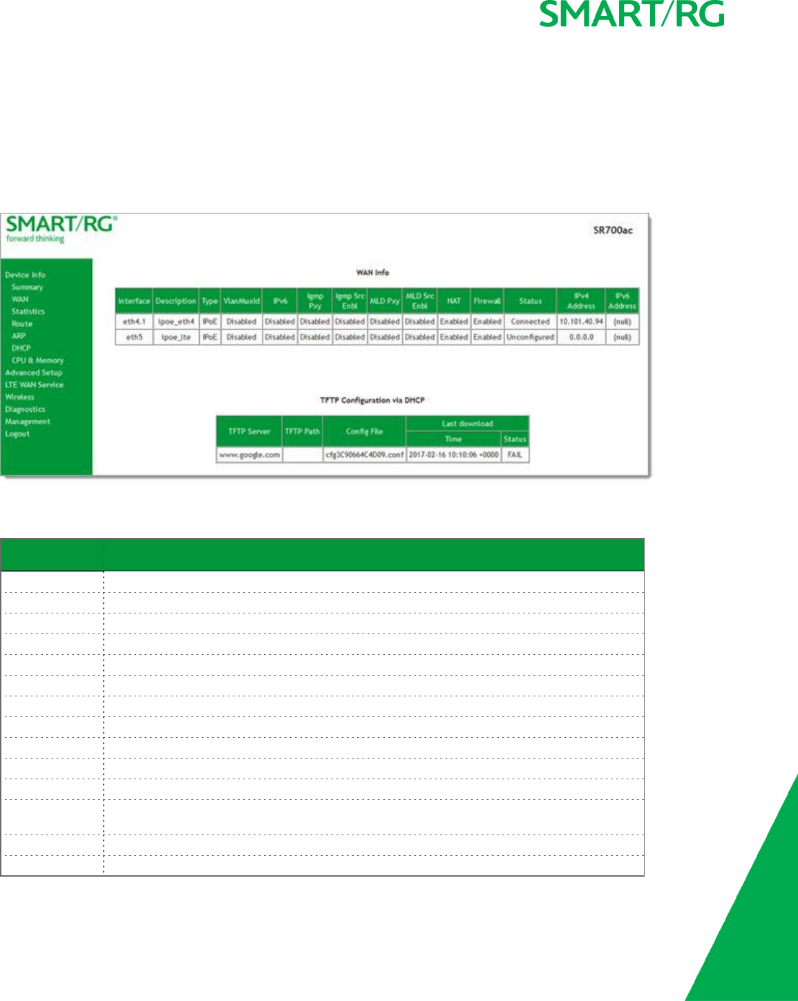
WAN
On this page, you can view information about the connection between your ISP and your gateway. The WAN interface can be DSL or
Ethernet and supports a number of Layer 2 and above configuration options (explained later in this document). Some features are
supported only on specific SmartRG models. Those exceptions are specified in this guide.
In the left navigation bar, click Device Info >WAN. The following page appears.
The fields on this page are explained in the following table.
Field Name Description
Interface The connection interface (Layer 2 interface) through which the gateway handles the traffic.
Description The service description such ipoe_0_0_1, showing the type of WAN and its ID.
Type The service type. Options are PPPoE,IPoE, and Bridge.
VlanMuxId The VLAN ID. Options are Disabled or 0-4094.
IPv6 The state of IPv6. Options are Enabled and Disabled.
Igmp Pxy The IGMP proxy. Options are Enabled and Disabled.
Igmp Src Enbl The IGMP source option. Options are Enabled and Disabled.
MLD Pxy The MLD proxy.
MLD Src Enbl The MLD source option. Options are Enabled and Disabled.
NAT The state of NAT. Options are Enabled and Disabled.
Firewall The state of the Firewall. Options are Enabled and Disabled.
Status The status of the WAN connection. Options are Disconnected,Unconfigured,Connecting, and
Connected.
IPv4 Address The obtained IPv4 address.
IPv6 Address The obtained IPv6 address.
SMARTRG INC. PROPRIETARY AND CONFIDENTIAL. ALL RIGHTS RESERVED. COPYRIGHT © 2017 12
Statistics
In this section, you can view network interface information for LAN, WAN Service, xTM and xDSL. All data is updated in 15-minute
intervals.
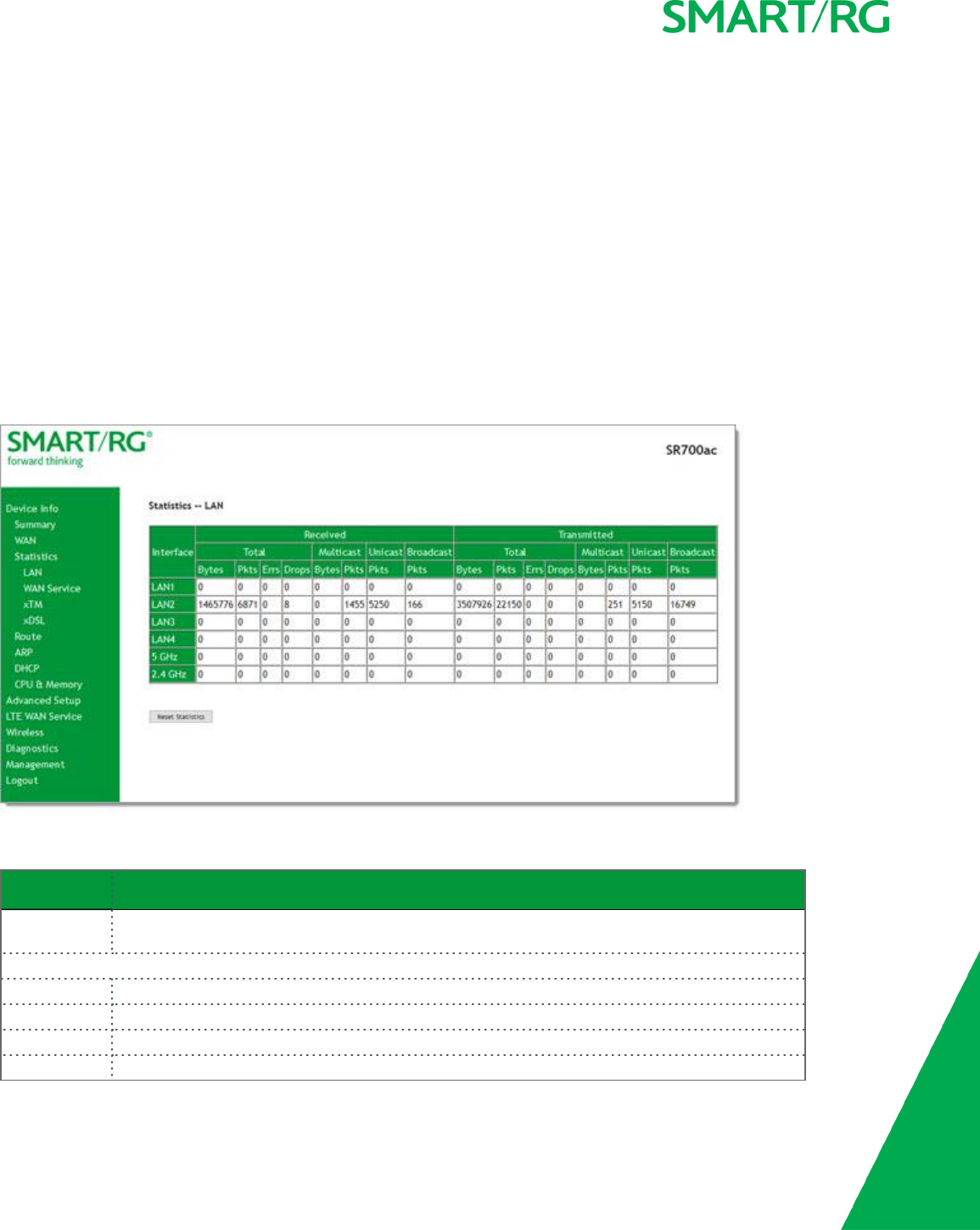
LAN
On this page, you can view the received and transmitted bytes, packets, errors and drops for each LAN interface configured on your
gateway. All local LAN Ethernet ports, Ethernet WAN ports and wireless Interfaces are included. For some models, statistics are
provided for multicast, unicast and broadcast traffic.
In the left navigation bar, click Device Info >Statistics. The Statistics -- LAN page appears where you can view detailed information
about the status of your LAN.
To reset the counters, click Reset Statistics near the bottom of the page.
The fields on this page are explained in the following table.
Field Name Description
Interface Available LAN interfaces. Options are LAN1 -LAN4,WAN (if configured on your device), and Wl0
(Wireless LAN-side interface), and 2.4 GHz and 5 GHz.
Received &Transmittedcolumns
Bytes Total number of packets in bytes.
Pkts Total number of packets.
Errs Total number of error packets.
Drops Total number of dropped packets.

SMARTRG INC. PROPRIETARY AND CONFIDENTIAL. ALL RIGHTS RESERVED. COPYRIGHT © 2017 13
WAN Service
On this page, you can view the received and transmitted bytes, packets, errors and drops for each WAN interface for your SmartRG
Gateway. All WAN interfaces configured for your gateway are included.
In the left navigation bar, click Device Info >Statistics >WAN Service. The Statistics -- WAN page appears where you can view
detailed information about the status of your WAN.
To reset the counters, click Reset Statistics near the bottom of the page.
The fields on this page are explained in the following table.
Field Name Description
Description Service description. Options are: pppoe,ipoe, and b.
Received &Transmittedcolumns
Bytes Total quantity of packets in bytes.
Pkts Total quantity of packets.
Errs Total quantity of error packets.
Drops Total quantity of dropped packets.
xTM
On this page, you can view the ATM/PTM statistics for your gateway. All WAN interfaces configured for your SmartRG gateway are
included.
In the left navigation bar, click Device Info >Statistics >xTM. The Interface Statistics page appears.
To reset these counters, click Reset Statistics near the bottom of the page.

SMARTRG INC. PROPRIETARY AND CONFIDENTIAL. ALL RIGHTS RESERVED. COPYRIGHT © 2017 14
The fields on this page are explained in the following table.
Field Name Description
Port Number Statistics for Port 1, or both ports if bonded.
In Octets Total quantity of received octets.
Out Octets Total quantity of transmitted octets.
In Packets Total quantity of received packets.
Out Packets Total quantity of transmitted packets.
In OAM Cells Total quantity of received OAM cells.
Out OAM Cells Total quantity of transmitted OAM cells.
In ASM Cells Total quantity of received ASM cells.
Out ASM Cells Total quantity of transmitted ASM cells.
In Packet Errors Total quantity of received packet errors.
In Cell Errors Total quantity of received cell errors.
SMARTRG INC. PROPRIETARY AND CONFIDENTIAL. ALL RIGHTS RESERVED. COPYRIGHT © 2017 15
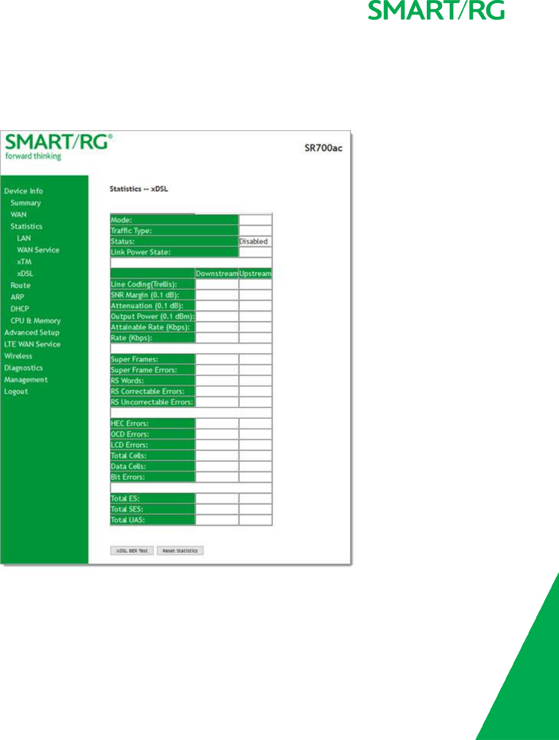
xDSL
On this page, you can view the DSL statistics for your gateway. All xDSL (VDSL or ADSL) interfaces configured for your SmartRG gate-
way are included. The terms and their explanations are derived from the relevant ITU-T standards and referenced accordingly.
1. In the left navigation bar, click Device Info >Statistics >xDSL. The Statistics - xDSL page appears.
2. To run an xDSL Bit Error Rate (BER) test (to determine the quality of the xDSL connection):
a. Scroll to the bottom of the page and click xDSL BER Test. The ADSL BER Test dialog box appears.
b. In the Tested Time field, select the duration in seconds and click Start. Options range from 1second to 360 seconds.
The test transfers idle cells containing a known pattern and compares the received data with this known pattern.
Comparison errors are tabulated and displayed.

SMARTRG INC. PROPRIETARY AND CONFIDENTIAL. ALL RIGHTS RESERVED. COPYRIGHT © 2017 16
3. To reset the counters, click Reset Statistics at the bottom of the page.
The fields on this page are explained in the following table.
Field Name Description
Mode xDSL mode that the modem has trained under, such as ADSL2+, G.DMT, etc.
Traffic Type Connection type. Options are: ATM,PTM and ETH.
Status Status of the connection. Options are: Up,Disabled,NoSignal, and Initializing.
Link Power State Current link power management state (e.g., L0, L2, L3).
Downstream and Upstream columns
Line Coding (Trellis) State of theTrellis Coded Modulation. Options are On and Off.
SNR Margin (0.1 db) The signal-to-noise ration margin (SNRM) is the maximum increase (in dB) of the
received noise power, such that the modem can still meet all of the target BERs
over all the frame bearers. [2]
Attenuation (0.1 db) The signal attenuation is defined as the difference in dB between the power
received at the near-end and that transmitted from the far-end. [2]
Output Power (0.1
dBm)
Transmit power from the gateway to the DSL loop relative to one Milliwatt (dBm).
Attainable Rate (Kbps) The typically obtainable sync rate, i.e., the attainable net data rate that the
receive PMS-TC and PMD functions are designed to support under the following con-
ditions:
lSingle frame bearer and single latency operation
lSignal-to-Noise Ratio Margin (SNRM) to be equal or above the SNR Target Mar-
gin
lBER not to exceed the highest BER configured for one (or more) latency
paths
lLatency not to exceed the highest latency configured for one (or more)
latency paths
lAccounting for all coding gains available (e.g., trellis coding, RS FEC) with
latency bound
lAccounting for the loop characteristics at the instant of measurement [2]
Rate (Kbps) The current net data rate of the xDSL link. Net data rate is defined as the sum of all
frame bearer data rates over all latency paths. [2]
Super Frames The number of xDSL Super Frames transmitted/received.
Super Frame Errors The number of xDSL Super Frames transmitted/received with errors.
RS Words The number of Reed-Solomon-based Forward Error Correction (FEC) codewords trans-
mitted/received.
RS Correctable Errors The number of Reed-Solomon-based FEC codewords received with errors that have
been corrected.
RS Uncorrectable
Errors
The number of Reed-Solomon-based FEC codewords received with errors that were
not correctable.
HEC Errors A count of ATM HEC errors detected. As per ITU-T G.992.1 and G.992.3, a1-byte HEC
is generated for each ATM cell header. Error detection is implemented as defined in
ITU-T I.432.1 with the exception that any HEC error shall be considered as a mul-

SMARTRG INC. PROPRIETARY AND CONFIDENTIAL. ALL RIGHTS RESERVED. COPYRIGHT © 2017 17
Field Name Description
tiple bit error, and therefore, HEC Error Correction is not performed. [1],[2]
OCD Errors Total number of Out-of-Cell Delineation errors. ATM Cell delineation is the process
which allows identification of the cell boundaries. The HEC field is used to achieve
cell delineation. [4] An OCD Error is counted when the cell delineation process trans-
itions from the SYNC state to the HUNT state. [2]
LCD Errors Total number of Loss of Cell Delineation errors. An LCD Error is counted when at
least one OCD error is present in each of four consecutive overhead channel periods
and SEF (Severely Errored Frame) defect is present. [2]
Total Cells The total number of cells (OAM and Data cells) transmitted/received.
Data Cells The total number of data cells transmitted/received.
Bit Errors The total number of Idle Cell Bit Errors in the ATM Data Path. [3]
Total ES Total number of Errored Seconds. This parameter is a count of 1-second intervals
with one or more CRC-8 anomalies. [4]
Total SES Total number of Severely Errored Seconds. An SES is declared if, during a 1-second
interval, there are 18 or more CRC-8 anomalies in one or more of the received
bearer channels, or one or more LOS (Loss of Signal) defects, or one or more SEF
(Severely Errored Frame) defects, or one or more LPR (Loss of Power) defects. [4]
Total UAS Total number of Unavailable Seconds. This parameter is a count of 1-second inter-
vals for which the xDSL line is unavailable. The xDSL line becomes unavailable at
the onset of 10 contiguous SESs. These 10 SES’s shall be included in the unavailable
time. Once unavailable, the xDSL line becomes available at the onset of 10 con-
tiguous seconds with no SESs. These 10 seconds with no SES’s shall be excluded from
unavailable time. [4]
References
[1] ITU-T Recommendation G.992.1 (1999), Asymmetric digital subscriber line (ADSL) transceivers.
[2] ITU-T Recommendation G.992.3 (2005), Asymmetric digital subscriber line transceivers 2 (ADSL2).
[3] ITU-T Recommendation G.997.1 (2006), Physical layer management for digital subscriber line (DSL) transceivers.
[4] ITU-T Recommendation I.432.1 (1999), B-ISDN user-network interface – Physical layer specification: General characteristics.
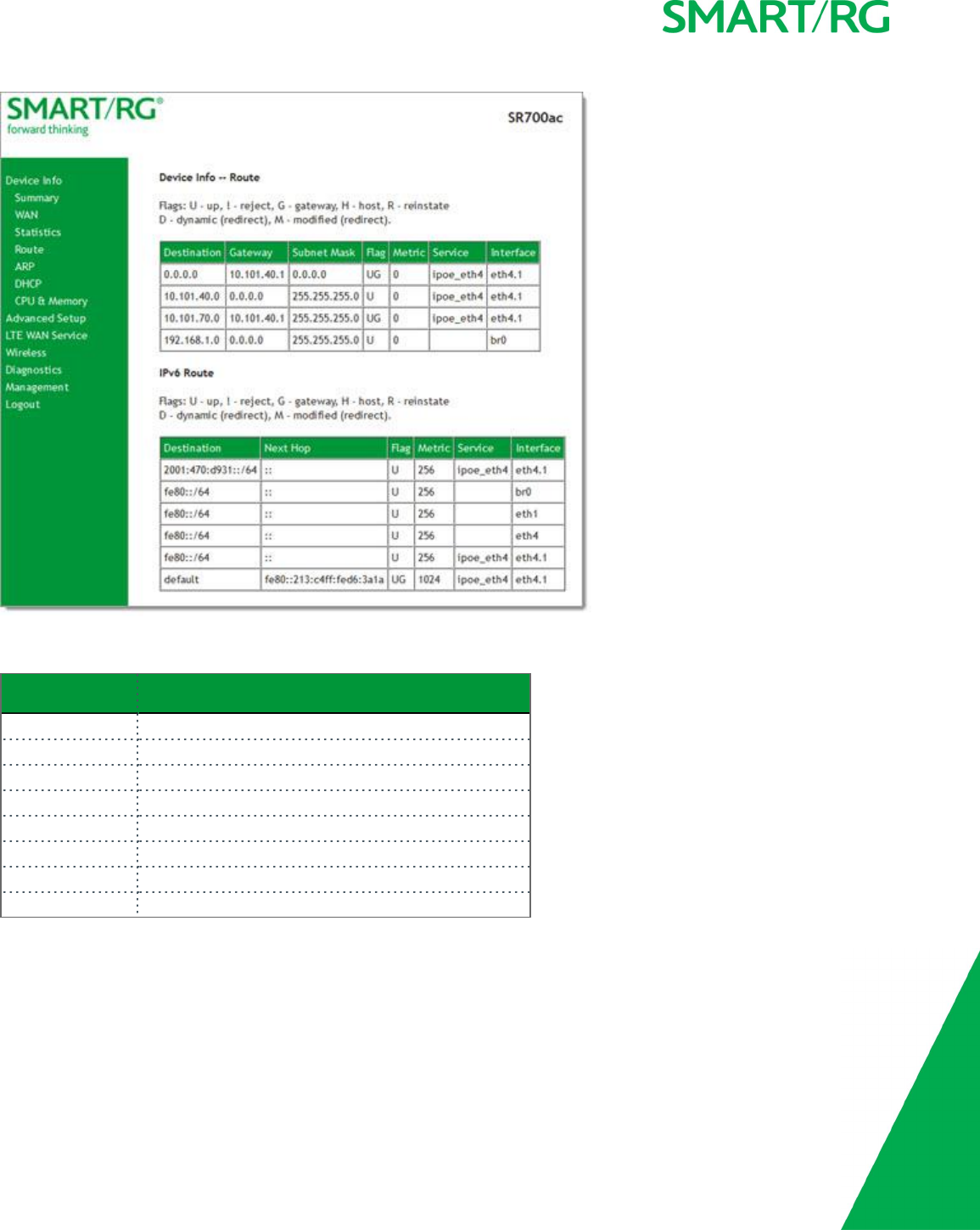
Route
On this page, you can view the LAN and WAN route table information configured in your SmartRG Gateway for both IPv4 and IPv6
implementation.
In the left navigation bar, click Device Info >Route. The following page appears.
SMARTRG INC. PROPRIETARY AND CONFIDENTIAL. ALL RIGHTS RESERVED. COPYRIGHT © 2017 18
The fields on this page are explained in the following table.
Field Description
Destination Destination IP addresses.
Gateway Gateway IP address.
Subnet Mask Subnet Masks.
Flag Status of the flags.
Metric Number of hops required to reach the default gateway.
Service Service type.
Interface WAN/LAN interface.
Next Hop (For IPv6 Route only) Next hop IP address.
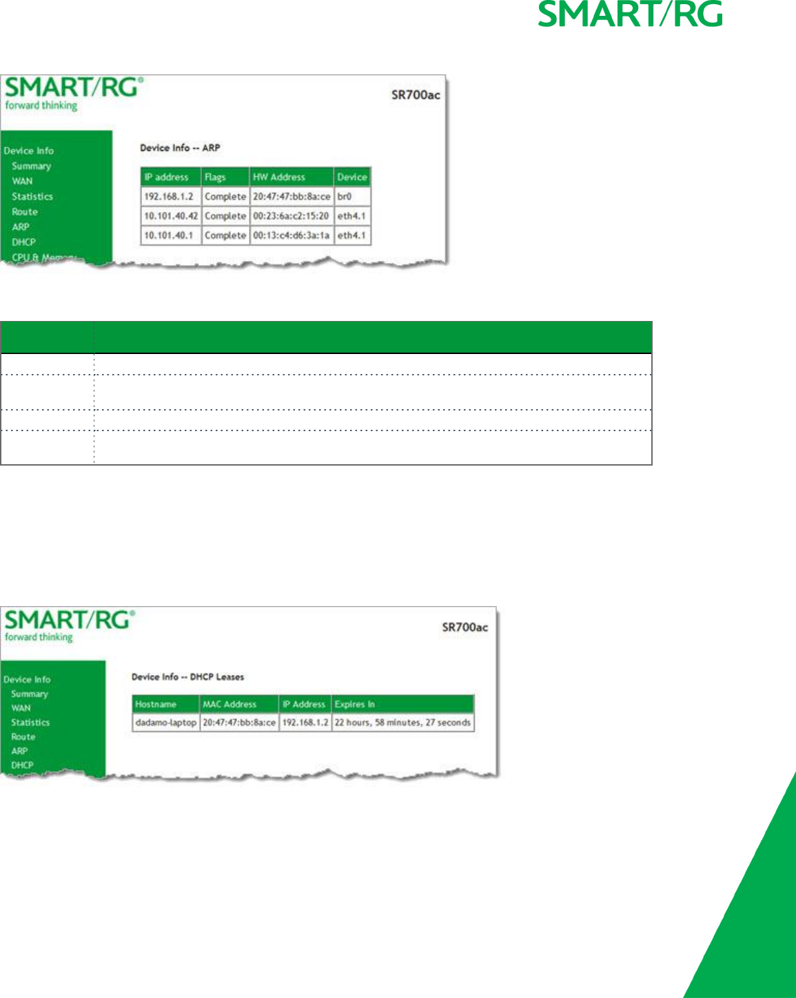
ARP
On this page, you can view the host IP addresses and their hardware (MAC) addresses for each LAN Client connected to the gateway
via a LAN Ethernet port or wireless LAN.
In the left navigation bar, click Device Info >ARP. The following page appears.
SMARTRG INC. PROPRIETARY AND CONFIDENTIAL. ALL RIGHTS RESERVED. COPYRIGHT © 2017 19
The fields on this page are explained in the following table.
Field Name Description
IP address The IP address of the host.
Flags Each entry in the ARP cache will be marked with one of these flags. Options are: Complete,Per-
manent, and Published.
HW Address The hardware (MAC) address of the host.
Device The system level interface by which the host is connected. Options are: br(n),atm(n),eth(n),
and atm(n).
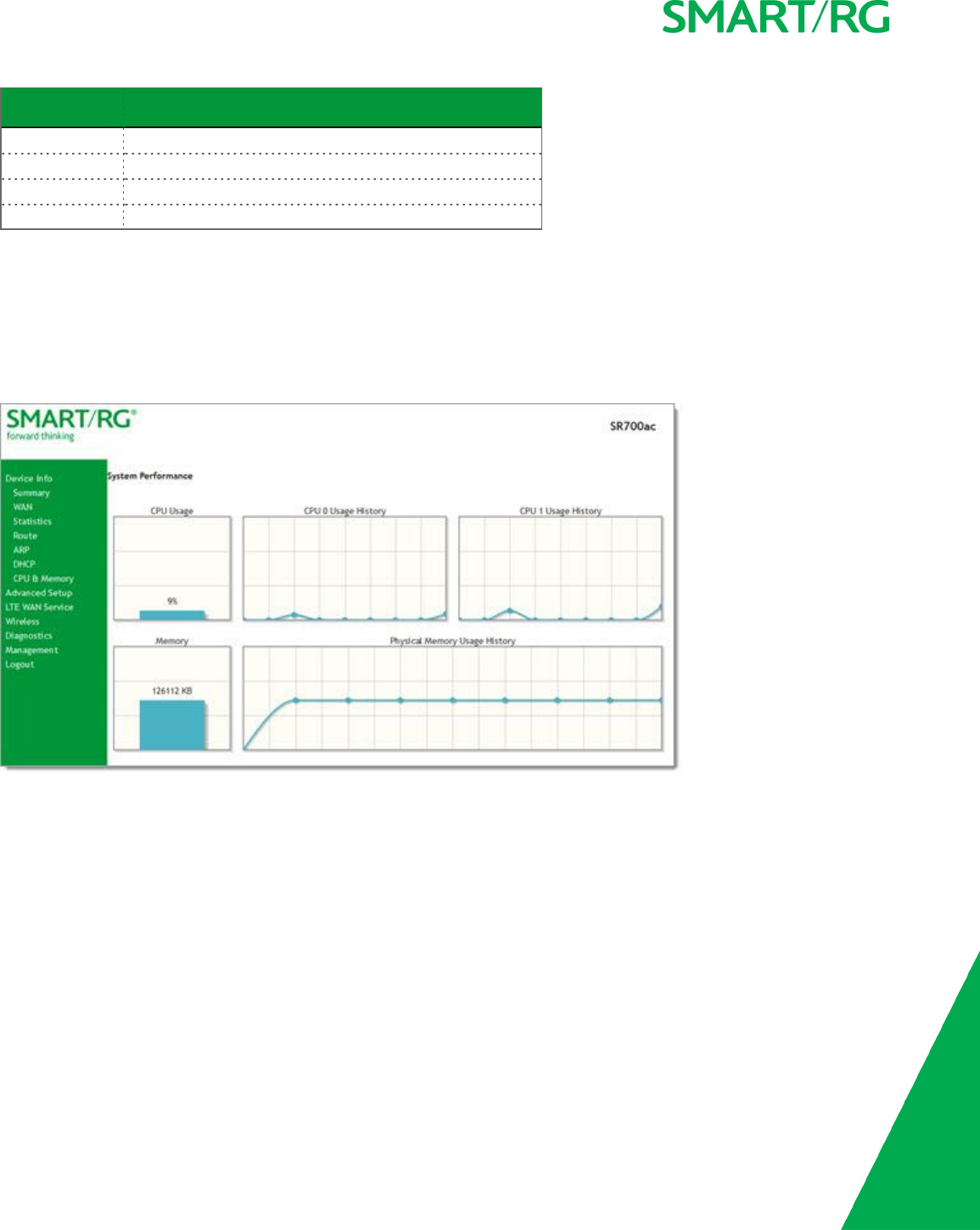
DHCP
The DHCP page displays a list of locally connected LAN hosts and their DHCP lease status, which are directly connected to the
SmartRG Gateway via a LAN Ethernet port or Wireless LAN.
In the left navigation bar, select Device Info >DHCP. The following page appears.
The fields on this page are explained in the following table.
SMARTRG INC. PROPRIETARY AND CONFIDENTIAL. ALL RIGHTS RESERVED. COPYRIGHT © 2017 20
Field Name Description
Hostname The host name of each connected LAN device.
MAC Address The MAC Address for each connected LAN device.
IP Address The IP Address for each connected LAN device.
Expires In The time until the DHCP lease expires for each LAN device.
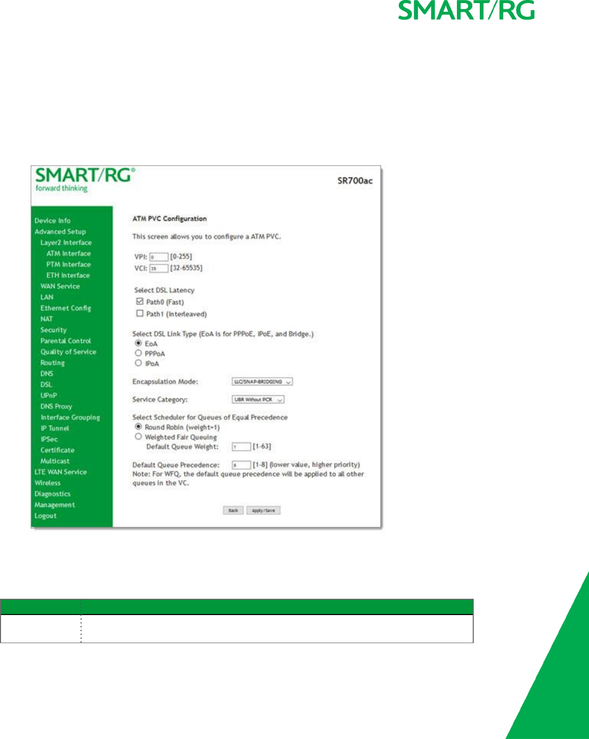
CPU & Memory
On this page, you can view the CPU and memory data for the gateway.
In the left navigation bar, click Device Info >CPU & Memory. The following page appears, showing the current usage and history.
The information refreshes automatically.
Advanced Setup
In this section, you can configure network interfaces, security, quality of service settings, and many other settings for your gateway
and network.
Layer2 Interface
In this section, you can configure interfaces for ATM, PTM and Ethernet interfaces. Generally you can accept the settings configured
by default. If your network is highly customized, you may need to modify some of the settings, such as Username and Password.
SMARTRG INC. PROPRIETARY AND CONFIDENTIAL. ALL RIGHTS RESERVED. COPYRIGHT © 2017 21
ATM Interface
On this page, you can configure Asynchronous Transfer Mode / Permanent Virtual Conduit (ATM/PVC) settings for your gateway. You
can customize latency options, link type, encapsulation mode and more.
Note: Devices (routers) on both ends of the connection must support ATM / PVC.
1. In the left navigation bar, click Advanced Setup >Layer2 Interface >ATM Interface and then click Add. The following page
appears.
2. Modify the settings as desired, using the information provided in the table below.
3. Click Apply/Save to commit your changes.
The fields on this page are explained in the following table.
Field Name Description
VPI Enter a Virtual Path Identifier. A VPI is an 8-bit identifier that uniquely identifies a network
path for ATM cell packets to reach its destination. A unique VPI number is required for each

SMARTRG INC. PROPRIETARY AND CONFIDENTIAL. ALL RIGHTS RESERVED. COPYRIGHT © 2017 22
Field Name Description
ATM path. This setting works with the VCI. Each individual DSL circuit must have a unique
VPI/VCI combination. String limits are: 0-255.
VCI Enter a Virtual Channel Identifier. A VCI is a 16-bit identifier that has a unique channel.
Options are: 32-65535.
Select DSL
Latency
Select the level of DSL latency. Options are:
lPath0 Fast: No error correction and can provide lower latency on error free lines.
lPath1 Interleaved: Error checking that provides error free data which increases
latency.
lPath0&1 Both: Fast & Interleaved.
Select Link Type Select the linking protocol. EoA is the most popular with PPPoA a close second (used with
many legacy ISPs). Options are:
lEoA: Ethernet over ATM.
lPPPoA: Point-to-Point Protocol over ATM.
lIPoA: Internet Protocol over ATM.
Encapsulation
Mode
Select whether multiple protocols or only one protocol is carried per PVC (Permanent Vir-
tual Circuit). Options are:
lLLC/ENCAPSULATION: (Available when PPPoA is selected as the Link Type) Logical
Link Control (LLC) encapsulation protocols used with multiple PVCs.
lLLC/SNAP-BRIDGING: (Available when EoA is selected as the Link Type) LLC used to
carry multiple protocols in a single PVC.
lLLC/SNAP-ROUTING: (Available when IPoA is selected as the Link Type) LLC used to
carry one protocol per PVC.
lVC/MUX: Virtual Circuit Multiplexer creates a virtual connection used to carry one
protocol per PVC.
Service Category Select the bit rate protocol. Options are:
lUBR without PCR: Unspecified Bit Rate with no Peak Cell Rate, flow control or time
synchronization between the traffic source and destination. Commonly used with
applications that can tolerate data / packet loss.
lUBR with PCR: Same as above but with a Peak Cell Rate.
lCBR: Constant Bit Rate relies on timing synchronization to make the network traffic
predictable. Used commonly in Video and Audio traffic network applications.
lNON Realtime VBR: Non Realtime Variable Bit Rate used for connections that trans-
port traffic at a Variable Rate. This category requires a guaranteed bandwidth and
latency. It does not rely on timing synchronization between the destination and
source.
lRealtime VBR: Realtime Variable Bit Rate. Same as the above option but relies on tim-
ing and synchronization between the destination and source. This category is com-
monly used in networks with compressed video traffic.
Minimum Cell
Rate
Minimum allowable rate (cells per second) at which cells can be sent on a ATM network. For
no shaping, enter -1.
SMARTRG INC. PROPRIETARY AND CONFIDENTIAL. ALL RIGHTS RESERVED. COPYRIGHT © 2017 23
Field Name Description
Scheduler for
Queues of Equal
Precedence as
the Default
Queue
The algorithm used to schedule the queue behavior. VC scheduling is unique from Default
Queues. Options are:
lWRR: Weighted Round Robin packets are accessed in a round robin style and classes
can be given.
lWFQ: Weighted Fair Queuing packets are assigned in a specific queue.
lDefault Queue Weight: The default weight of the specified queue. Options are: 1-
63.
lDefault Queue Precedence: The precedence of the specified group. Options are: 1-8
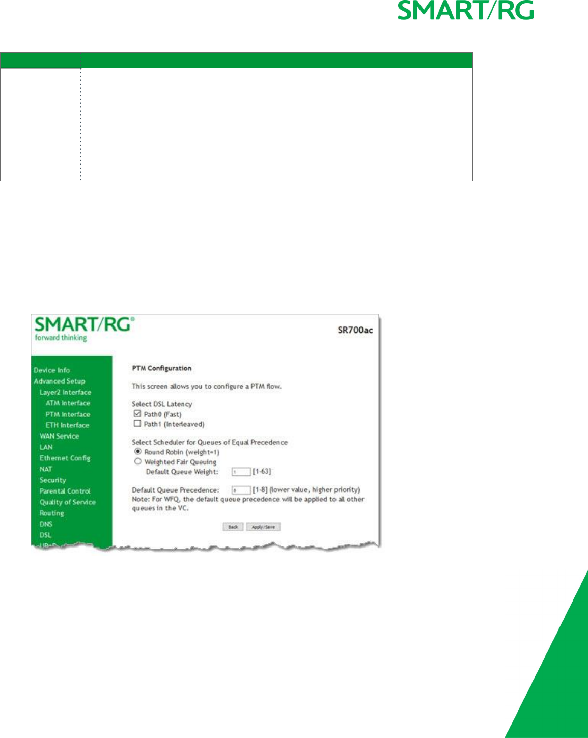
PTM Interface
The SmartRG gateway's VDSL2 standards support Packet Transfer Mode (PTM). An alternative to ATM mode, PTM transports packets
(IP, PPP, Ethernet, MPLS, and others) over DSL links. For more information, refer to the IEEE802.3ah standard for Ethernet in the First
Mile (EFM). Some 500 series gateways have a PTM interface configured by default.
On this page, you can configure a PTM interface for your gateway.
1. In the left navigation bar, click Advanced Setup >Layer2 Interface >PTM Interface and then click Add. The following page
appears.
2. Modify the settings as desired.
3. Click Apply/Save to commit your changes.
The fields on this page are explained in the following table.

SMARTRG INC. PROPRIETARY AND CONFIDENTIAL. ALL RIGHTS RESERVED. COPYRIGHT © 2017 24
Field Name Description
Select DSL Latency Select the level of DSL latency. Options are:
lPath0 Fast: No error correction and can provide lower latency on error-free
lines.
lPath1 Interleaved: Error checking that provides error-free data which
increases latency.
Select Scheduler for
Queues of Equal Pre-
cedence as the
Default Queue
Select an algorithm for applying queue data priority. Options are:
lWeighted Round Robin: Time slices are assigned to each process in equal por-
tions and in circular order, handling all processes without priority (also known
as cyclic executive).
lWeighted Fair Queuing: A data packet scheduling technique allowing dif-
ferent scheduling priorities to be assigned to statistically multiplexed data
flows. Since each data flow has its own queue, an ill-behaved flow (that sent
larger packets or more packets per second than the others since it became
active) will only affect itself and not other sessions.
Default Queue
Weight
Enter a default weight of the specified queue. Options are: 1-63.
Default Queue Pre-
cedence
Enter a precedence for the specified queue. Options are: 1-8.
ETH Interface
If you are using a gateway that is Ethernet-specific (non-DSL), you may want to configure an ETH interface to manage communication.
Most models support Ethernet and can be configured for Ethernet and DSL at the same time. Your gateway has four LAN ports. One
of them can be re-purposed to become an RJ45 WAN port when needed.
On this page, you can configure an Ethernet interface for your gateway.
1. In the left navigation bar, click Advanced Setup >Layer2 Interface >ETH Interface.
2. If no WAN port is configured, the Add button appears. Click Add.

SMARTRG INC. PROPRIETARY AND CONFIDENTIAL. ALL RIGHTS RESERVED. COPYRIGHT © 2017 25
3. If a WAN port is already configured or you clicked Add, the following page appears.
Note: If a WAN port it is already configured, you must remove it before you can define a new one. Before you can remove the
existing port, you must first modify or delete any WAN service that uses it. The Add button does not appear until the existing
port is removed.
4. Select the LAN port you wish to act as a WAN port.
5. Click Apply/Save to commit your changes.
6. To remove the WAN interface, click the Remove checkbox and then click the Remove button.

SMARTRG INC. PROPRIETARY AND CONFIDENTIAL. ALL RIGHTS RESERVED. COPYRIGHT © 2017 26
WAN Service
In this section, you can configure WAN services for:
l"xPPP over Ethernet"
l"IP over Ethernet"
l"Bridging"
A sample configuration scenario is provided for each variation.
xPPP over Ethernet
There are several parts to configuring a PPP over Ethernet WAN service. You will progress through several pages to complete the
configuration.
1. In the left navigation bar, click Advanced Setup >WAN Service and then click Add. The following page appears.
2. Select the Layer2 interface to use for the WAN service.
SMARTRG INC. PROPRIETARY AND CONFIDENTIAL. ALL RIGHTS RESERVED. COPYRIGHT © 2017 27
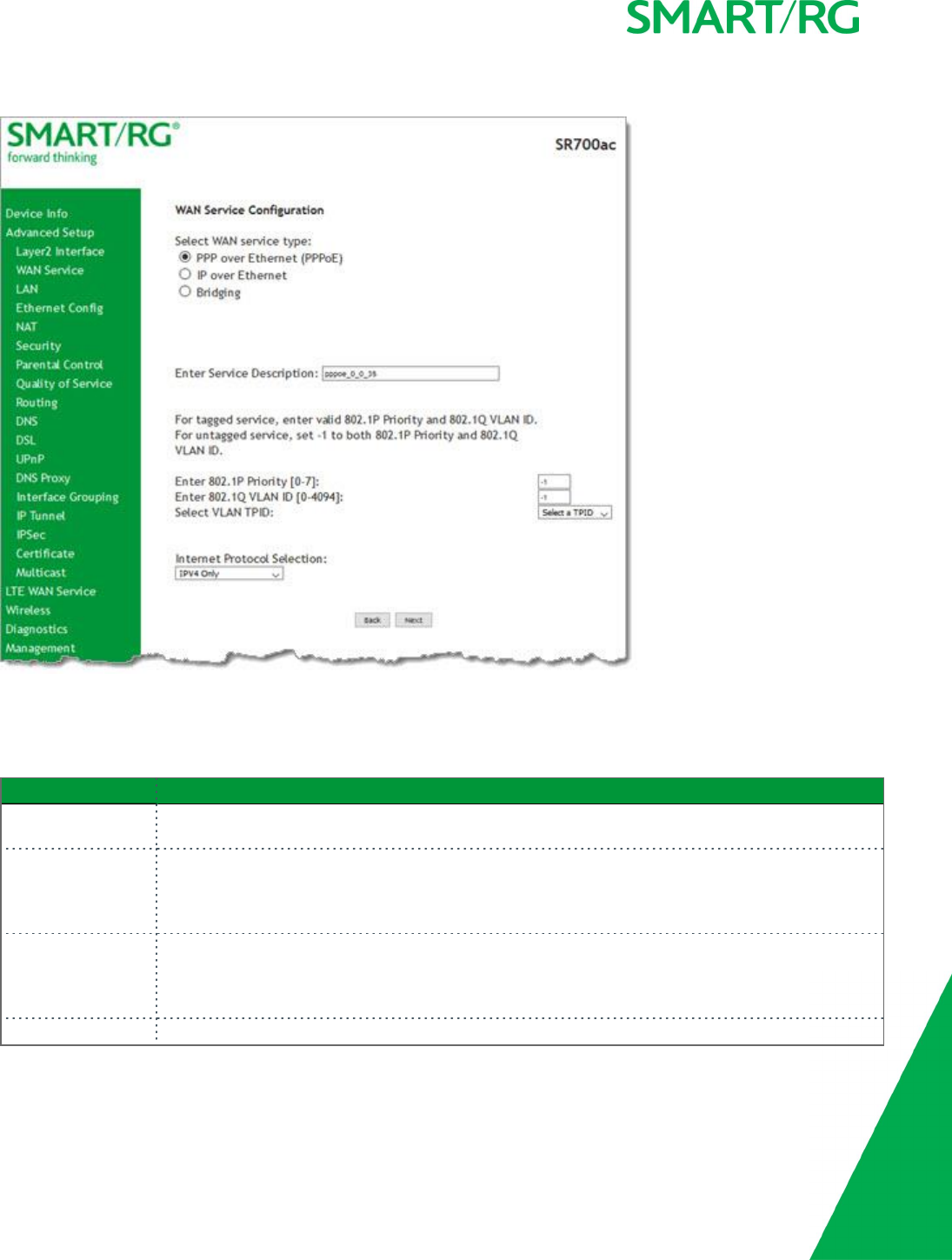
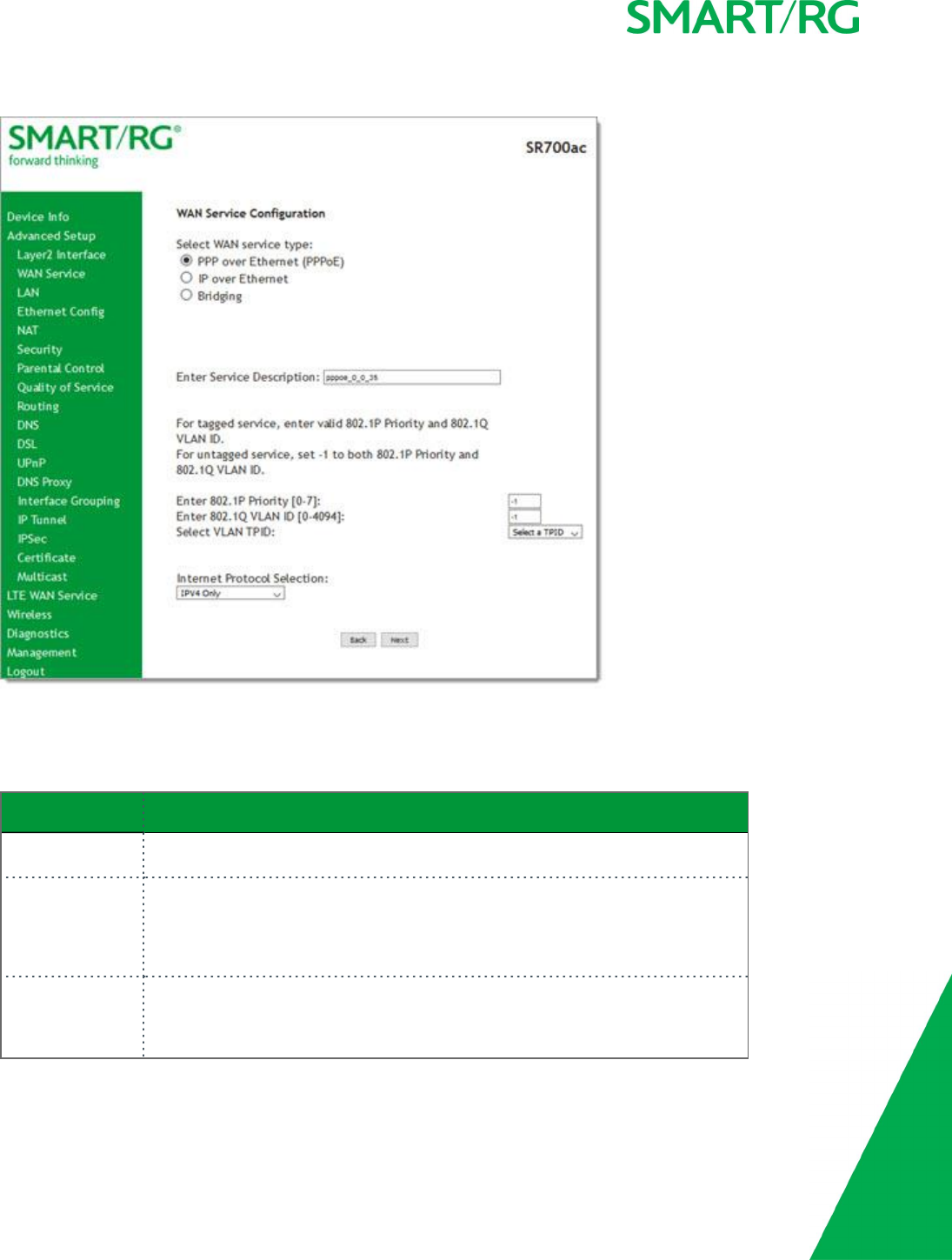
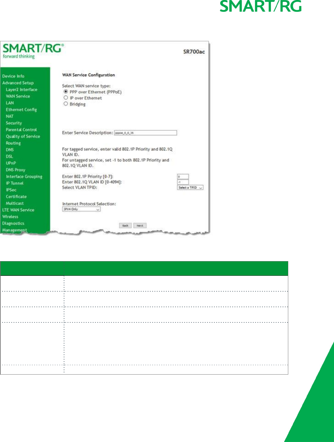
3. Click Next. The following page appears.
4. Accept the default of PPP over Ethernet (PPPoE) WAN service type.
5. Modify the other settings as needed.
The fields on this page are explained in the following table.
Field Name Description
Enter Service
Description
Enter a name to describe this configuration.
Enter 802.1P Priority Options are 0-7. The default is 0.
For tagged service, enter values in this field and the 802.1Q VLAN ID field.
For untagged service, enter -1 (disabled) in this field and the 802.1Q VLAN ID field.
Enter 802.1Q VLAN ID Options are 0-4094. The default is -1 (disabled).
For tagged service, enter values in this field and the 802.1P Priority field.
For untagged service, enter -1 (disabled) in this field and the 802.1P Priority field.
Select VLAN TPID Select the TPID for this VLAN. Options are 0x8100,0x88A8, and 0x9100.
SMARTRG INC. PROPRIETARY AND CONFIDENTIAL. ALL RIGHTS RESERVED. COPYRIGHT © 2017 28
Field Name Description
Internet Protocol
Selection
Different scheduling priorities can be applied to statistically multiplexed data flows. Since each data
flow has its own queue, an ill-behaved flow (which has sent larger packets or more packets per
second than the others) will only punish itself and not other sessions. Options are IPv4 Only,
IPv4&IPv6 (Dual Stack), and IPv6 Only.
Note: When you select IPV4&IPV6 or IPV6, the subsequent options presented will change accord-
ingly.
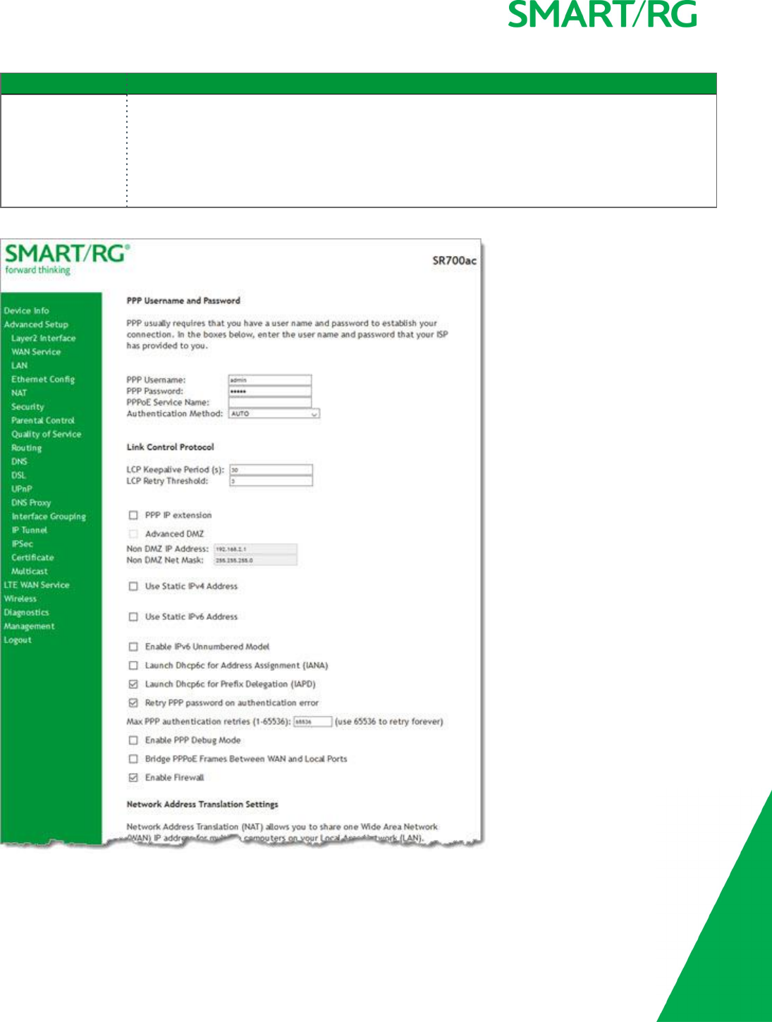
6. Click Next. The following page appears where you will configure the PPP Username, Password and related information.

SMARTRG INC. PROPRIETARY AND CONFIDENTIAL. ALL RIGHTS RESERVED. COPYRIGHT © 2017 29
7. Modify the fields as needed.
The fields on this page are explained in the following table.
Field Name Description
PPP Username Enter the username required for authentication to the PPP server.
PPP Password Enter the password required for authentication to the PPP server.
PPPoE Service Name (Optional) Enter a description for this service.
Authentication Method Select a means for authentication. Options are:
lAUTO: Attempt to automatically detect handshake protocols
(listed below). This is the default.
lPAP: Password Authentication Protocol (plaintext pass-
words).
lCHAP: Challenge Handshake Authentication Protocol. (MD5
hashing scheme on passwords).
lMSCHAP: Microsoft Challenge Handshake Authentication Pro-
tocol. (Microsoft encrypted password authentication pro-
tocol).
LCP Keepalive Period The frequency at which the keepalive packet is sent by the gateway
to the PPP server.
LCP Retry Threshold Enter the number of additional attempted packets that the gateway
will send (in the event that the PPP server does not respond to the
Keepalive) before giving up and declaring the connection as Failed.
PPP IP Extension Select whether to forward all traffic to the advanced DMZ IP spe-
cified in the next field.
Advanced DMZ (Available when PPP IP Extension is selected) Specify the IP
address and net mask to which PPPoE traffic is forwarded.
Use Static IPv4 Address Specify the IPv4 Address to apply for this WAN service in the IPv4
Address field that appears.
Use Static IPv6 Address Specify the IPv6 Address to apply for this WAN service in the IPv6
Address field that appears.
Enable IPv6 Unnumbered
Model
Click to enable IP processing on a serial interface without assigning it
an explicit IP address. The IP address of another interface can be
can "borrow" the IP address of another interface already configured
on the router, which conserves network and address space.
Launch Dhcp6c for Address
Assignment (IANA)
(Available only for IPv6 environments) Select this option for the CPE
to receive the WAN IP from the ISP.
Launch Dhcp6c for Prefix
Delegation (IAPD)
(Available only for IPv6 environments) This option is enabled by
default. The CPE generates the WAN IP's prefix from the server's
REST by MAC address. Click the checkbox to disable this option.
Retry PPP password on
authentication error>
Enter the maximum number of PPP authentication retries on failure
in the Max PPP authentication retries field. Options are 1-65536.
The default is 65536 (unlimited retries).

SMARTRG INC. PROPRIETARY AND CONFIDENTIAL. ALL RIGHTS RESERVED. COPYRIGHT © 2017 30
Field Name Description
Enable PPP Debug Mode Select to have the system put more PPP connection information into
the system log of the device. This is for debugging errors and not for
normal usage.
Bridge PPPoE Frames
Between WAN and Local
Ports
Select to enable PPPoE passthrough to relay PPPoE connections from
behind the modem. Also known as Half-Bridged mode.
Enable Firewall This option enables functions in the Security sub-menu and is
enabled by default. Click the checkbox to disable this option.
Network Address Translation Settings section
Enable NAT This option is selected by default and enables sharing the WAN inter-
face across multiple devices on the LAN. Click the checkbox to dis-
able NAT.
Enable Fullcone NAT (Available only when Enable NAT is selected) Click to enable one-
to-one NAT.
Enable SIP ALG (Available only when Enable NAT is selected) Click to enable Ses-
sion Initiation Protocol (SIP) pass-through NAT. Used for Voice over IP
(VOIP) applications.
IGMP Multicast section
Enable IGMP Multicast
Proxy
Click to enable Internet Group Membership Protocol (IGMP) mul-
ticast. Used by IPv4 hosts to report multicast group memberships to
any neighboring multicast routers.
Enable IGMP Multicast
Source
Select to enable this service to act as an IGMP multicast source.
MLD Multicast section
Enable MLD Multicast Proxy Click to enable Multicast Listener Discovery (MLD) multicast. Used by
IPv4 hosts to report multicast group memberships to any neighboring
multicast routers.
Enable MLD Multicast
Source
Select to enable this service to act as an MLD multicast source.
MTU size Enter the MTU (Maximum Transmission Unit) size for SmartRG gate-
ways supporting a gigabit-capable WAN interface. Options are 1370 -
1492 bytes. The default is 1492 bytes.
Use Base MAC Address on
this WAN interface
Use the SmartRG Devices Base (Primary) MAC address. When
unchecked, a unique MAC is assigned for each service.
Enable MAC Clone (Appears when Use Base MAC Address is NOT selected) Enter the
MAC address to be used as the close address.
8. Click Next. The following page appears where you will select the interface used as a default gateway used for the PPP ser-
vice being created.
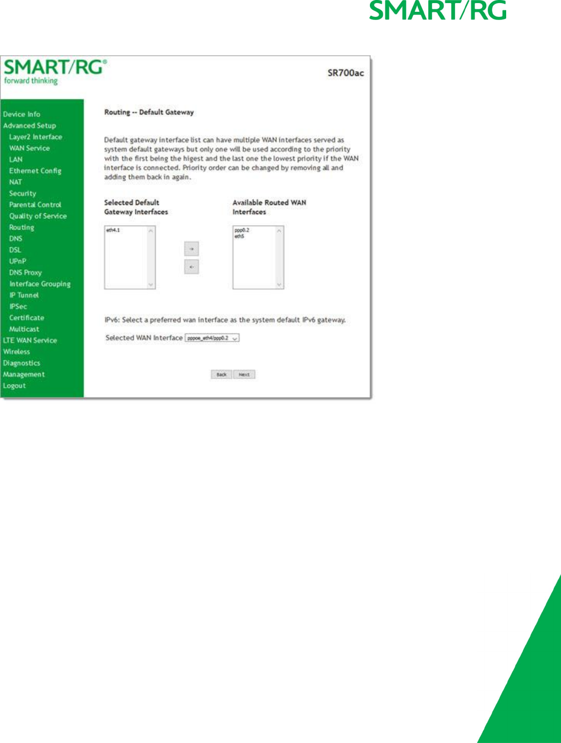
SMARTRG INC. PROPRIETARY AND CONFIDENTIAL. ALL RIGHTS RESERVED. COPYRIGHT © 2017 31
9. Click the arrows to move your selection from left to right or from right to left.
SMARTRG INC. PROPRIETARY AND CONFIDENTIAL. ALL RIGHTS RESERVED. COPYRIGHT © 2017 32
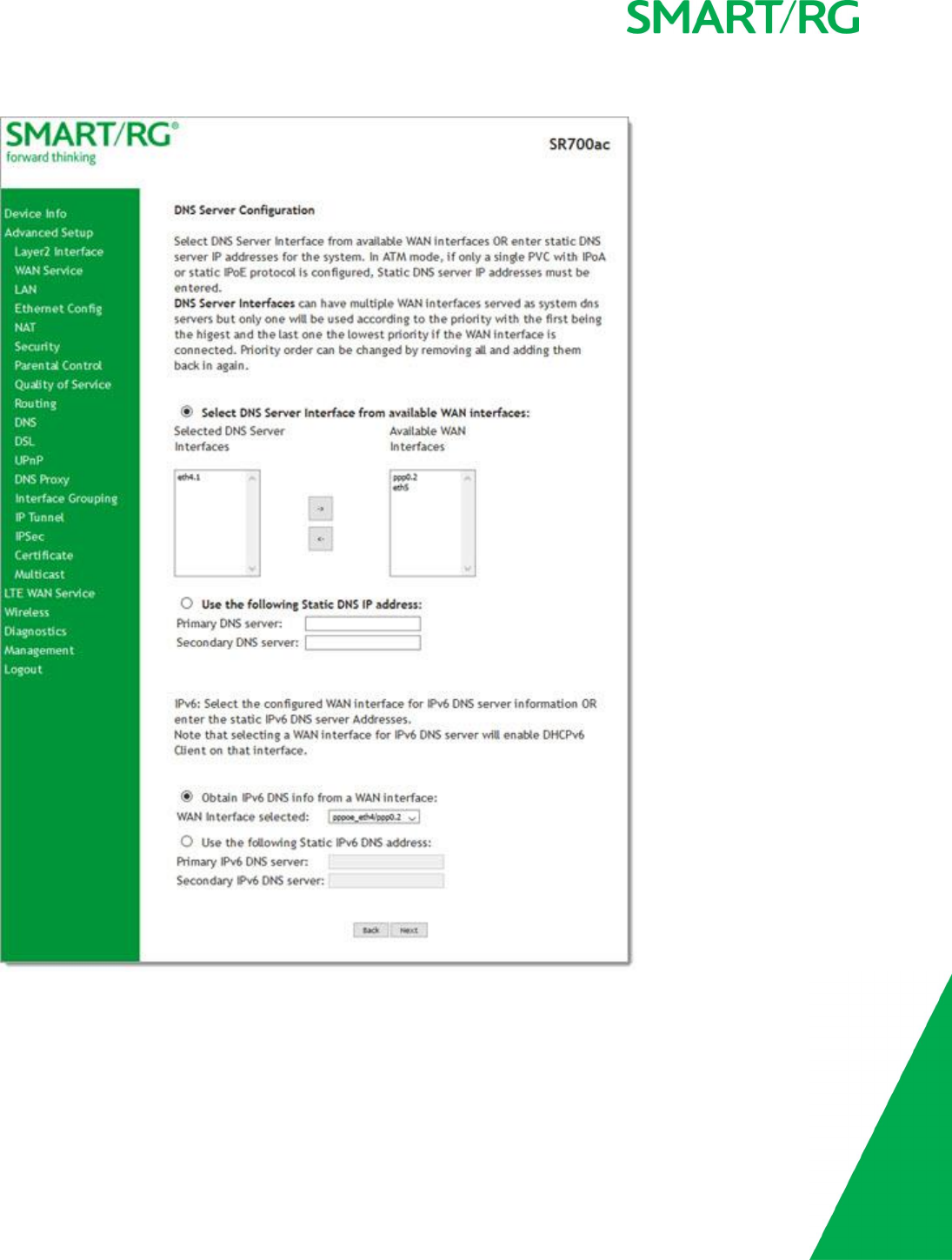
10. Click Next. The following page appears where you will select DNS Server settings.
11. Select the DNS server interface from the available WAN interfaces.
12. Click the arrows to move your selection from left to right or from right to left.
13. Alternatively, you can enter static DNS IP addresses in the Use the following Static DNS IP address section.
SMARTRG INC. PROPRIETARY AND CONFIDENTIAL. ALL RIGHTS RESERVED. COPYRIGHT © 2017 33
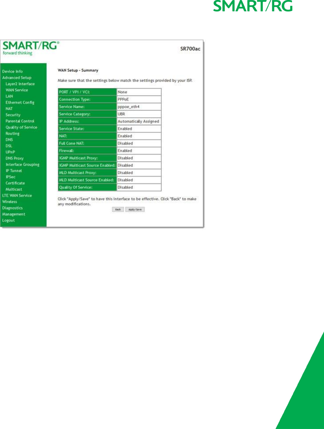
14. Click Next. The summary page appears indicating that your PPPoE WAN setup is complete.
15. Review the summary and either click Apply/Save to commit your changes or click Back to step through the pages in reverse
order to make any necessary alterations.
IP over Ethernet
There are several parts to configuring a IP over Ethernet WAN service. You will progress through several pages to complete the con-
figuration.

SMARTRG INC. PROPRIETARY AND CONFIDENTIAL. ALL RIGHTS RESERVED. COPYRIGHT © 2017 34
1. In the left navigation bar, click Advanced Setup >WAN Service and then click Add. The following page appears.
SMARTRG INC. PROPRIETARY AND CONFIDENTIAL. ALL RIGHTS RESERVED. COPYRIGHT © 2017 35
2. Select the Layer2 interface to use for the WAN service and click Next. The following page appears.
3. Select the IP over Ethernet WAN service type.
4. Modify the other fields as needed.
The fields on this page are explained in the following table.
Field Name Description
Enter Service
Description
(Optional) Enter a name to describe this configuration.
Enter 802.1P Pri-
ority
Enter a priority for this WAN service. Options are 0-7. The default is 0.
For tagged service, enter values in this field and the 802.1Q VLAN ID field.
For untagged service, enter -1 (disabled) in this field and the 802.1Q VLAN ID field.
Enter 802.1Q VLAN
ID
Enter the VLAN ID for this WAN service. Options are 0-4094. The default is -1 (dis-
abled).
For tagged service, enter values in this field and the 802.1P Priority field.
SMARTRG INC. PROPRIETARY AND CONFIDENTIAL. ALL RIGHTS RESERVED. COPYRIGHT © 2017 36
Field Name Description
For untagged service, enter -1 (disabled) in this field and the 802.1P Priority field.
Select VLAN TPID Select the TPID for this VLAN. Options are 0x8100,0x88A8, and 0x9100.
Internet Protocol
Selection
This data packet scheduling technique allows different scheduling priorities to be
applied to statistically multiplexed data flows. Since each data flow has its own
queue, an ill-behaved flow (which has sent larger packets or more packets per
second than the others since it became active) will only punish itself and not other
sessions. Options are IPv4 Only,IPv4&IPv6 (Dual Stack), and IPv6 Only. The default
is IPv4 Only.
Note: When you select IPV4&IPV6 or IPV6, the options presented on the following
screens change accordingly.
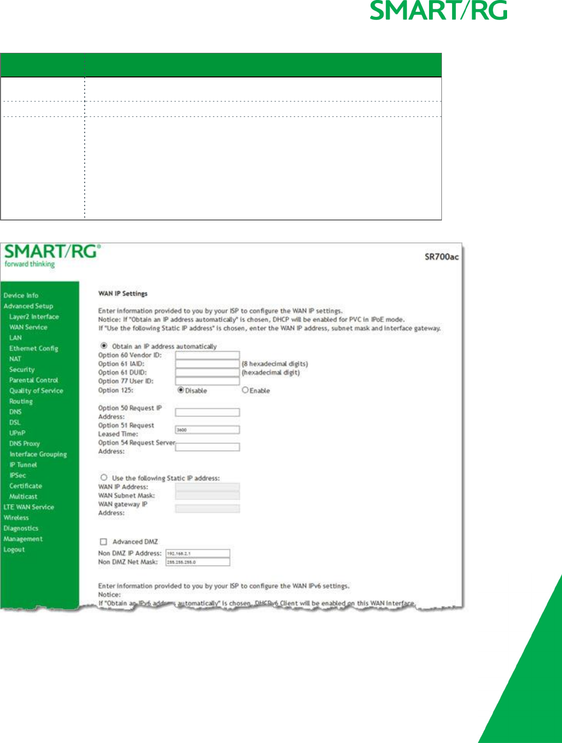
5. Click Next. The following page appears.

SMARTRG INC. PROPRIETARY AND CONFIDENTIAL. ALL RIGHTS RESERVED. COPYRIGHT © 2017 37
6. Enter the relevant WAN IP Settings.
The fields on this page are explained in the following table.
Field Name Description
Obtain an IP address auto-
matically
When you wish the ISP to automatically assign the WAN IP to the gateway.
Option 60 Vendor ID (Optional) Broadcast a specific vendor ID for the DHCP server to accept the device.
Option 61 IAID (Optional) Interface Association Identifier (IAID). A unique identifier for an IA, chosen by the
client.
Option 61 DUID (Optional) DHCP Unique Identifier (DUID) is used by the client to get an IP address from the
DHCP server.
Option 77 User ID (Optional) Enter the user class ID that should be used to filter traffic.
Option 125 (Optional) Select whether to enable local devices to automatically receive DHCP options
from the server.
Option 50 Request IP Address Select to request a specific IP address when sending messages. If the address is not avail-
able, the DHCP server assigns the next allowed IP address.
Option 51 Request Leased
Time
Select to request the maximum lease time defined for the client.
Option 54 Request Server
Address
Select to request the IP address of the source server.
Use the following Static IP
address
Select this option to manually declare the static IP information provided by your ISP.
WAN IP Address If using a static IP address, enter the static WAN IPV4 Address.
WAN Subnet Mask If using a static IP address, enter the static Subnet Mask.
WAN gateway IP Address If using a static IP address, enter the static Gateway IP address.
Advanced DMZ (Optional) Select this option to enable Advanced DMZ on the WAN service.
Non DMZ IP Address If using the Advanced DMZ feature, you can enter a specific vendor ID that will be broadcast
for the DHCP server to accept the device, y. e.g., 192.168.2.1..
Non DMZ Net Mask If using the Advanced DMZ feature, you can enter a secondary LAN IP address for the gate-
way. The default is 255.255.255.0.
IPv6 settings section
The following fields appear when either IPv6 Only or IPv4&IPv6 (Dual Stack) network protocol values is selected on the
WAN Service Configuration page.
Obtain an IPv6 address auto-
matically
Enables the DHCPv6 Client on this WAN interface. Select this option when you want the ISP
to automatically assign the WAN IP to the gateway.
Dhcpv6 Address Assignment
(IANA)
Select this option for the CPE to receive WAN IP from ISP.
Dhcpv6 Prefix Delegation
(IAPD)
This option is selected by default and enables the CPE to generate the WAN IP's prefix from
the server's REST by MAC address.
Use the following Static IPv6
address
Select this option to manually declare the v6 Static IP information provided by your ISP. In
the WAN IPv6 Address/Prefix Length field, enter the IP address / prefix length. If you do
SMARTRG INC. PROPRIETARY AND CONFIDENTIAL. ALL RIGHTS RESERVED. COPYRIGHT © 2017 38
Field Name Description
not specify a prefix length, the default of /64 is used.
Specify the Next-Hop IPv6
address
In the WAN Next Hop IPv6 Address field, enter the IP address of the next WAN in the group.
This address can be either a local link or a global unicast IPv6 address.
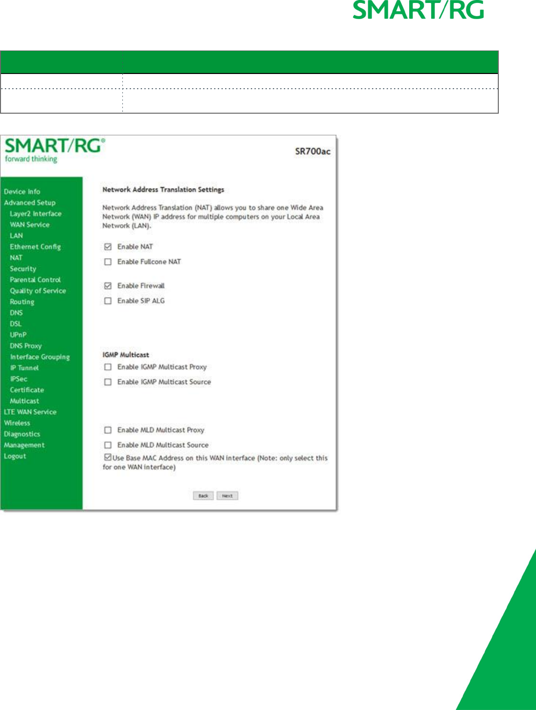
7. Click Next. The following page appears.
8. Modify the settings if desired. All settings are optional.
Network Address Translation (NAT) allows you to share one Wide Area Network (WAN) IP address for multiple computers on
your Local Area Network (LAN). If you do not want to enable NAT (atypical) and wish the user of this gateway to access the
Internet normally, you need to add a route on the uplink equipment. Failure to do so will cause access to the Internet to fail.
The fields on this page are explained in the following table.

SMARTRG INC. PROPRIETARY AND CONFIDENTIAL. ALL RIGHTS RESERVED. COPYRIGHT © 2017 39
Field Name Descriptopn
Enable NAT This option is enabled by default and supports sharing the WAN interface
across multiple devices on the LAN. Also enables the functions in the NAT
sub-menu and addition PPPoE NAT features to select. Click the checkbox to
disable NAT.
Enable Fullcone NAT Enables one-to-one NAT.
Enable Firewall This option is enabled by default and enables functions in the Security
sub-menu.
Enable SIP ALG Click to enable Session Initiation Protocol (SIP) pass-through NAT. Used for
Voice over IP (VOIP) applications.
IGMP Multicast section
Enable IGMP Multicast
Proxy
Click to enable Internet Group Membership Protocol (IGMP) multicast.
Used by IPv4 hosts to report multicast group memberships to any neigh-
boring multicast routers.
Enable IGMP Multicast
Source
Click to enable this service to act as an IGMP multicast source.
MLD Multicast section
Enable MLD Multicast
Proxy
Click to enable multicast filtering. Used by IPv4 hosts to report multicast
group memberships to any neighboring multicast routers.
Enable MLD Multicast
Source
Click to enable this service to act as a multicast source.
Use Base MAC Address
on this WAN interface
Click to use the gateway's base (Primary) MAC address. Otherwise, a unique
MAC is assigned for each service.
Enable MACClone (Appears when Use Base MAC Address is NOT selected) Enter the MAC
address to be used as the close adddress.
9. For the remaining WAN Service configuration pages, use the instructions provided in the default gateway step in the PPP
over Ethernet section.
Bridging
Before you can configure a bridge WAN service, you must create the related ATM interface.
Note: This feature is available for SR515ac models only.

SMARTRG INC. PROPRIETARY AND CONFIDENTIAL. ALL RIGHTS RESERVED. COPYRIGHT © 2017 40
1. In the left navigation bar, click Advanced Setup >WAN Service and then click Add. The following page appears.
SMARTRG INC. PROPRIETARY AND CONFIDENTIAL. ALL RIGHTS RESERVED. COPYRIGHT © 2017 41
2. Select an ATM interface for the WAN service and then click Next. The following page appears.
3. Select Bridging. The multicast source fields appear.
4. Modify the fields as needed, using the information in the following table.
Field Name Description
Allow as IGMP Multicast
Source
Select to enable this service to act as an IGMP multicast source.
Allow as MLD Multicast
Source
Select to enable this service to act as an MLD multicast source.
Enter Service Descrip-
tion
(Optional) Enter a name to describe this configuration.
Enter 802.1P Priority Enter the priority for this WAN service. Options are 0-7. The default is -1 (disabled).
For tagged service, enter values in this field and the 802.1Q VLAN ID field.
For untagged service, accept the default of -1 in this field and in the 802.1Q VLAN ID
field.
Enter 802.1Q VLAN ID Enter the VLAN ID for this WAN service. Options are 0-4094. The default is -1 (disabled).
SMARTRG INC. PROPRIETARY AND CONFIDENTIAL. ALL RIGHTS RESERVED. COPYRIGHT © 2017 42
Field Name Description
For tagged service, enter values in this field and the 802.1P Priority field.
For untagged service, enter -1 (disabled) in this field and in the 802.1P Priority field.
Select VLAN TPID (Optional) Select the TPID for this VLAN. Options are 0x8100,0x88A8, and 0x9100.
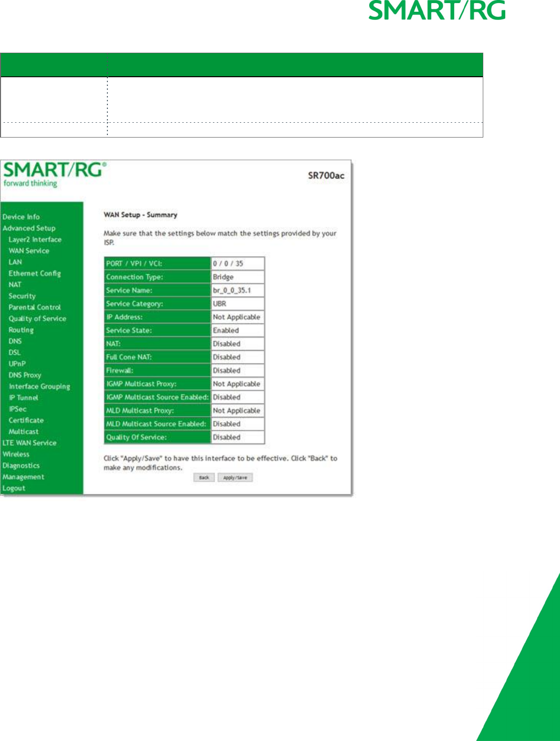
5. Click Next. The summary page appears indicating that your Bridging WAN setup is complete.
6. Review the summary and either click Apply/Save to commit your changes or click Back to step through the pages in reverse
order to make any necessary alterations.

SMARTRG INC. PROPRIETARY AND CONFIDENTIAL. ALL RIGHTS RESERVED. COPYRIGHT © 2017 43
LAN
On the Local Area Network (LAN) Setup page, you can configure the router’s local IP addresses, subnet mask, DHCP behavior and
other related LAN side settings for your gateway.
1. In the left navigation bar, click Advanced Setup >LAN. The following page appears.

SMARTRG INC. PROPRIETARY AND CONFIDENTIAL. ALL RIGHTS RESERVED. COPYRIGHT © 2017 44
2. Customize the fields as desired.
3. Click Apply/Save to commit your changes.
The fields on this page are explained in the following table.
Field Name Description
GroupName Select an interface group from the list of available groups (defined on the Interface
Grouping page).
IP Address Enter the LAN IP address to be used by LAN devices connecting to this gateway.
Subnet Mask Enter the subnet mask to be used by LAN devices connecting to this gateway.
Enable IGMP Snooping Select to enable your gateway to listen to IGMP network traffic between hosts and
routers. By listening to these conversations, the gateway maintains a map of which
links need which IP multicast streams.
Standard Mode Allows multicast traffic will flood to all bridge ports when there is no client sub-
scribed to any multicast group.
Blocking Mode Blocks multicast data traffic, preventing it from flooding to all bridge ports when no
client subscriptions to a multicast group are present. This option is enabled by
default.
Enable IGMP LAN to
LAN Multicast
Allows multicast traffic between LANs. Options are Disable and Enable. The default
is Disable.
Enable LAN Side Fire-
wall
Enables the restriction of traffic between LAN hosts.
Disable DHCP Server Prevents the DHCP functionality of your gateway from automatically assigning LAN
IPaddresses to host devices as they connect with the gateway.
Enable DHCP Server Allows the DHCP functionality of your gateway to automatically assign LAN IP
addresses to host devices as they connect with the gateway. This option is selected
by default.
Fill in the next three fields to configure this action.
Start IP Address Enter the beginning of the class C IP address range to be assigned by the DHCP
server.
End IP Address Enter the end of the class C IP address range to be assigned by the DHCP server.
Leased Time (hour) Enter the number of hours for which an IP address will be leased. The default is 24
hours.
Static IP Lease List Specify a static IP address to be associated with a specific MAC Address of one of
your LAN host devices. Click Add Entries. Enter the MAC address and IP address and
click Apply/Save. Repeat this step to create any additional entries that you need.
Automatically create
static IP leases from
the following OUIs
For LAN hosts, IP addresses can be assigned manually or by using DHCP. Click Add
OUI. Enter the OUI and click Apply/Save. Repeat this step to create any additional
entries that you need.
Configure DHCP
Options
Enter information for the following three DHCP options:
lOption 66: For some devices that also require access to a TFTP server (device
configuration name filesare in .cnf file format), which enables the device to
communicate with other infrastructure, select this option to specify the
name of the TFTP server. Option 66 is an IEEE standard.

SMARTRG INC. PROPRIETARY AND CONFIDENTIAL. ALL RIGHTS RESERVED. COPYRIGHT © 2017 45
Field Name Description
lOption 150: Enter a comma-separated list of TFTP IPv4 server addresses. The
maximum allowed is 2.
lOption 43: Enter the loopback address of the master controller in ASCII
format.
Configure the second
IP address and sub-
net mask for LAN
interface
When you select this option, the IP Address and Subnet Mask fields appear where
you can enter a second IP address and Subnet mask to support a second, sim-
ultaneous LAN.
For example, the primary LAN might be defined as 192.168.0.1 and this secondary LAN
defined as 192.168.2.1.
IPv6 Autoconfig
On this page, you can configure your gateway's IPv6 environment.
SMARTRG INC. PROPRIETARY AND CONFIDENTIAL. ALL RIGHTS RESERVED. COPYRIGHT © 2017 46
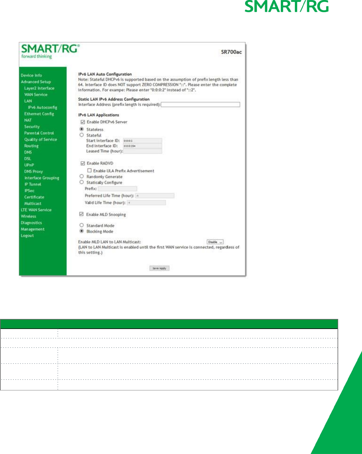
1. In the left navigation bar, click Advanced Setup >LAN >IPv6 Autoconfig . The following page appears.
2. Modify the fields as needed, using the information in the table below.
3. Click Save/Apply to commit your changes.
The fields on this page are explained in the following table.
Field Name Description
Interface Address IPV6 address to assign as the gateways Local LAN IPV6 address and prefix length. Prefix length is required.
IPv6 LAN Applications section
Enable DHCPv6
Server
This option is selected by default. Click to disable the DHCPv6 feature on the LAN.
Stateless This option is selected by default. Click to stop inheriting IPV6 address assignments from the WAN IPV6 inter-
face.
Stateful Click this option to identify the DHCPv6 server given by the LAN IPV6 network as configured with additional

SMARTRG INC. PROPRIETARY AND CONFIDENTIAL. ALL RIGHTS RESERVED. COPYRIGHT © 2017 47
Field Name Description
options. Zero compression is not supported. Make sure to enter zeros between the colons, that is, do not
use shorthand notation (::2). Options are:
lStart interface ID: Enter the beginning IPv6 available addresses for DHCP to assign to LAN devices.
lEnd interface ID: Enter the ending IPv6 available addresses for DHCP to assign to LAN devices.
lLeased Time (hour): Amount of time before a new IPv6 lease is requested by the LAN client.
Enable RADVD (Optional) This option is enabled by default. It enables Router Advertisement Daemon (RADVD) service that
sends router advertisements to LAN clients. Clear the check box to disable RADVD. Options are:
lRandomly Generate: This option is selected by default. The prefix is generated automatically.
lEnable ULA Prefix Advertisement: Check this option to enable unique local address (ULA) advert-
isement on the LAN. When you select this option, the Randomly Generate option is selected and the
gateway can generate a random IPv6 prefix.
lStatically Configure: Select this option to configure the IPv6 prefix, and enter values in the Prefix,
Preferred Life Time, and Valid Life Time fields (in hours). The default value for the Time fields is -1
(no limit).
Enable MLD Snooping (Optional) This option is enabled by default. It enables Multicast Listener Discovery (MLD) snooping to man-
age IPV6 multicast traffic. Options are:
lStandard Mode: Multicast traffic will flood to all bridge ports when no client subscribes to a mul-
ticast group even if IGMP snooping is enabled.
lBlocking Mode: The multicast data traffic will be blocked and not flood to all bridge ports when
there are no client subscriptions to any multicast group. This is the default.
Enable MLD LAN to
LAN Multicast
(Optional) This option is enabled by default. It enables LAN-to-LAN Multicast until the first WAN service is
connected. Options are Disable and Enable. The default is Disable.
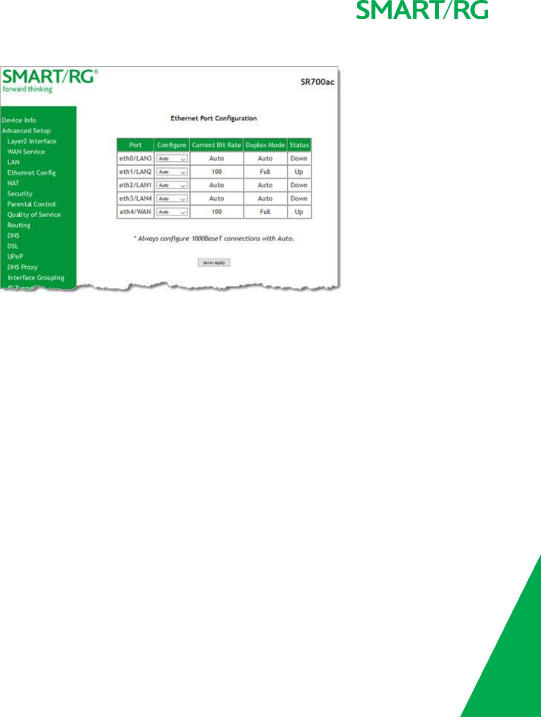
Ethernet Config
On this page, you can set the speed and duplex mode for the Ethernet ports and the WAN port, if configured,
SMARTRG INC. PROPRIETARY AND CONFIDENTIAL. ALL RIGHTS RESERVED. COPYRIGHT © 2017 48
1. In the left navigation bar, click Advanced Setup >Ethernet Config . The following page appears.
2. In the Configure column, select an option (Auto,100 Full,100 Half,10 Full or 10 Half) for each of the four Ethernet ports
on your gateway.
These options represent 100 megabits or 10 megabits using half or full duplex transmission protocols. When you have a spe-
cific device with a known limited transmission speed capability, select one of the latter four options. If you select Auto, your
gateway will automatically select an appropriate setting based on Ethernet auto negotiation with the NIC of the LAN host.
Note: Always select Auto for 1000 BaseT connections.
3. Click Apply/Save to commit your changes.

SMARTRG INC. PROPRIETARY AND CONFIDENTIAL. ALL RIGHTS RESERVED. COPYRIGHT © 2017 49
NAT
In this section, you can configure the settings for Network Address Translation including setting up virtual servers, port triggering
and a DMZ host. There is seldom need to customize these settings as the default settings manage the related features sufficiently
for most environments.
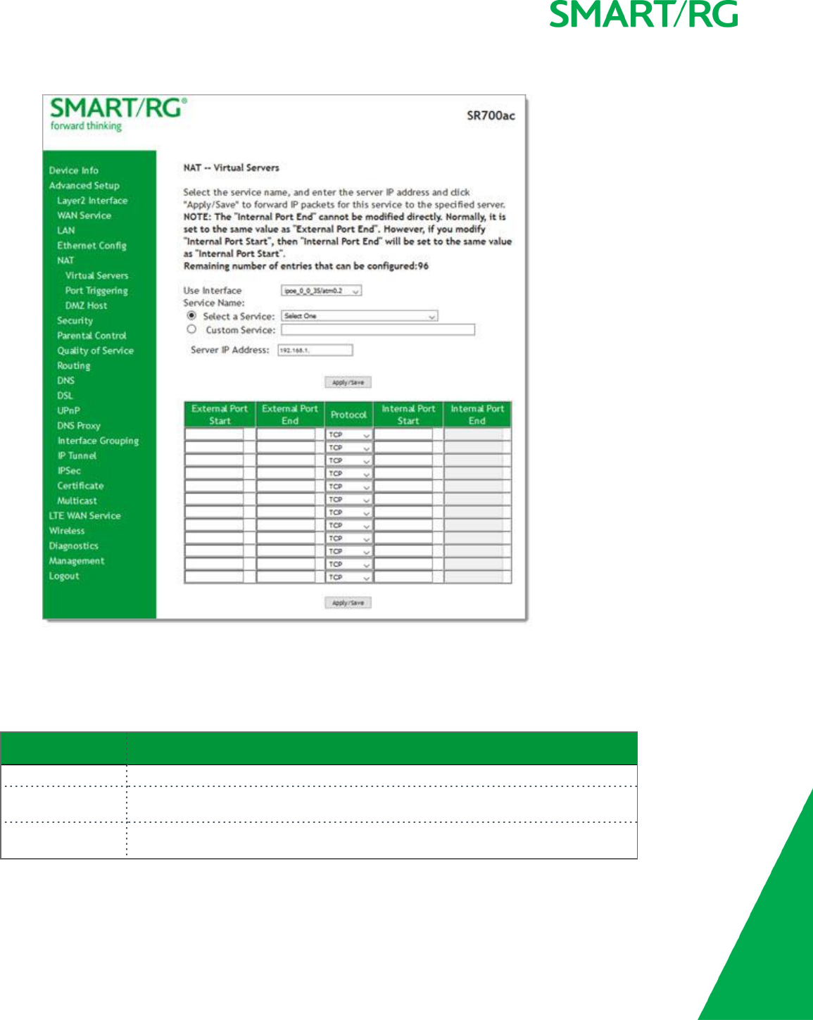
Virtual Servers
Virtual Servers (more commonly known as Port Forwards) is a technique used to facilitate communications by external hosts with ser-
vices provided within a private local area network.
On this page, you can configure the virtual server settings for your gateway.
SMARTRG INC. PROPRIETARY AND CONFIDENTIAL. ALL RIGHTS RESERVED. COPYRIGHT © 2017 50
1. In the left navigation bar, select Advanced Setup > NAT and then click Add. The following page appears.
2. Customize the fields to create your port forwarding entry.
3. Click Apply/Save to commit your changes. The servers for the selected service appear on the NAT Virtual Servers Setup
page.
The fields on this page are explained in the following table.
Field Name Description
Use Interface Select the WAN interface to which this NAT rule will apply.
Select a Service Select from a list of application that typically require port forwards configured. The
port ranges and protocol fields will be pre-populated.
Custom Service If your application does not appear in the Select a Service list, you can enter a unique
name for the application in this field.
SMARTRG INC. PROPRIETARY AND CONFIDENTIAL. ALL RIGHTS RESERVED. COPYRIGHT © 2017 51
Field Name Description
Server IP Address Enter the IP address of the LAN client where the service is hosted.
External Port Start Enter the first external port for this server.
External Port End Enter the last external port for this server.
Protocol Select the protocol to be used with this range of ports. Options are: TCP,UDP, or
TCP/UDP.
Internal Port Start Enter the first internal port for this server.
Internal Port End Enter the last internal port for this server.
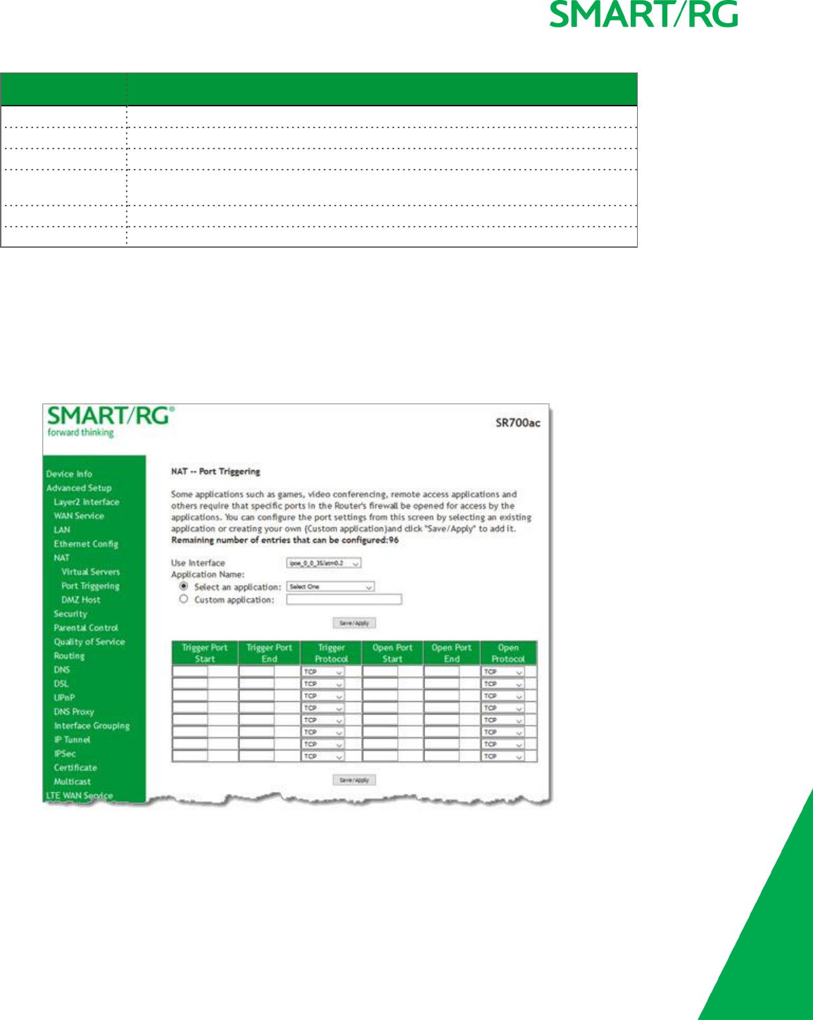
Port Triggering
Some applications require that specific ports in the gateway's firewall be opened for access by remote parties. The Port Trigger fea-
ture dynamically opens up the open ports in the firewall when an application on the LAN initiates a TCP/UDP connection to a remote
party using the triggering ports. The gateway allows the remote party from the WAN side to establish new connections back to the
application on the LAN side using the Open Ports.
1. In the left navigation bar, click Advanced Setup >NAT >Port Triggering and then click Add. The following page appears.
2. Customize the fields as needed for the firewall pinholes you wish to establish. A maximum 96 entries can be configured.
3. Click Save/Apply to commit your changes. The selected service appears on the NAT Port Triggering Setup page.
The fields on this page are explained in the following table.
SMARTRG INC. PROPRIETARY AND CONFIDENTIAL. ALL RIGHTS RESERVED. COPYRIGHT © 2017 52
Field Name Description
Use Interface Select the interface for which the port triggering rule will apply.
Select an Application Select the application which requires a port trigger entry. The Port and Protocol
fields are populated.
Custom Application If the application you want does not appear in the selection list, enter a unique name
for the application for which you are creating a port trigger entry.
Trigger Port Start Enter the starting number of the range of available outgoing trigger ports. Options
are: 1-65535.
Trigger Port End Enter the end number of the range of available outgoing trigger ports. Options are: 1-
65535.
Trigger Protocol Select the protocol required by the application that will be using the ports in the spe-
cified range. Options are: TCP,UDP, and TCP/UDP.
Open Port Start Enter the starting number of the range of available incoming ports. Options are: 1-
65535.
Open Port End Enter the end number of the range of available incoming ports. Options are: 1-
65535.
Open Protocol Select the protocol for the open port. Options are: TCP,UDP, and TCP/UDP.
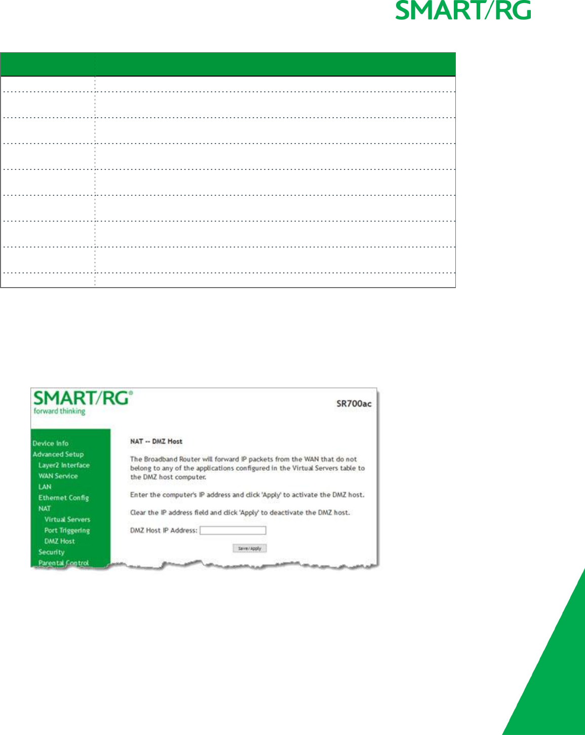
DMZ Host
The Broadband Router will forward IP packets from the WAN that do not belong to any of the applications configured in the Virtual
Servers table to the DMZ host computer. If you want to route all internet traffic to a specific LAN device with no filtering or security,
add the IP address of that device to this page.
1. In the left navigation bar, click Advanced Setup >NAT >DMZ Host. The following page appears.
2. Enter the DMZ Host IP Address.
3. Click Save/Apply to commit the new or changed address.
SMARTRG INC. PROPRIETARY AND CONFIDENTIAL. ALL RIGHTS RESERVED. COPYRIGHT © 2017 53
Security
In this section, you can configure filtering for IP and MAC.
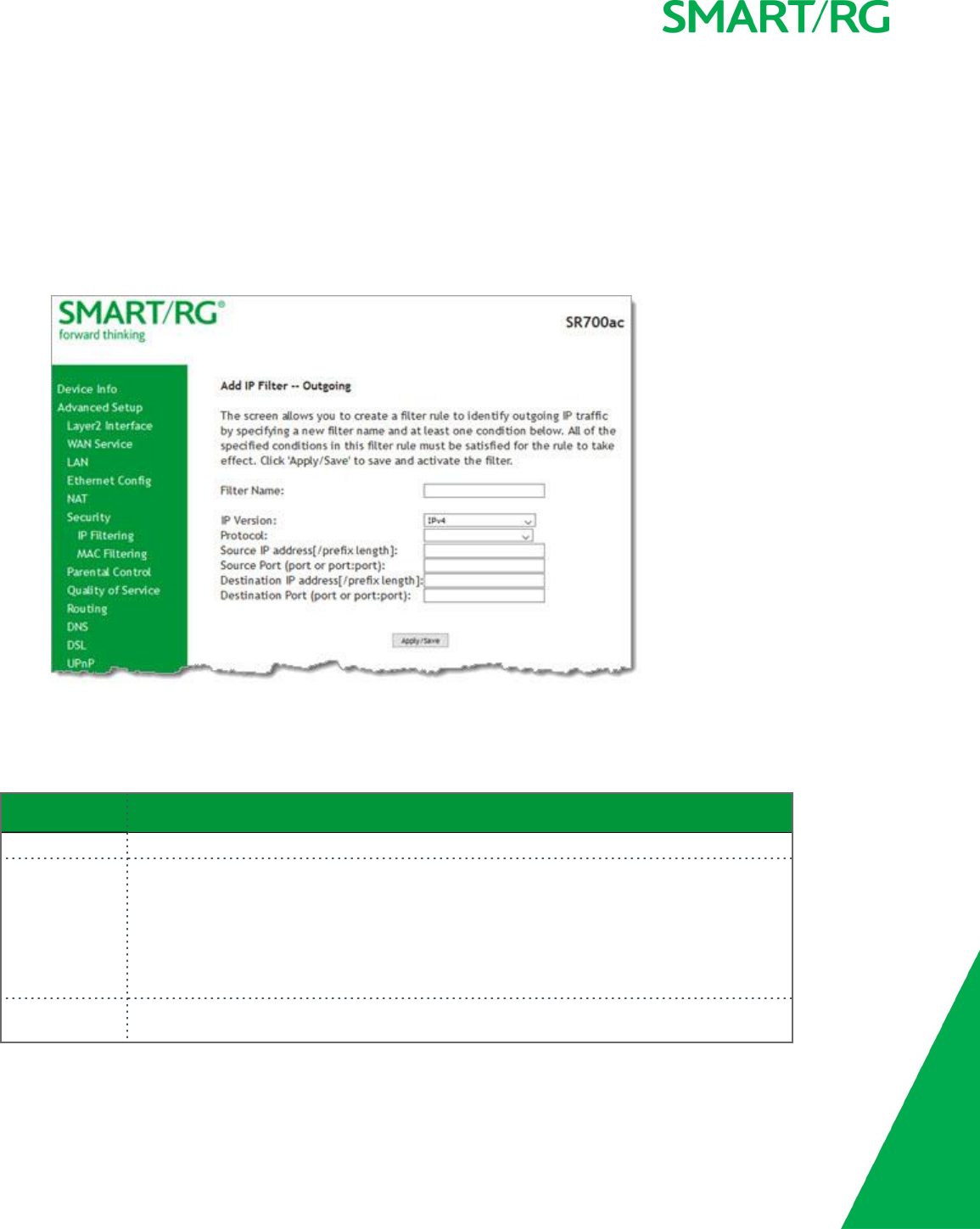
IP Filtering - Outgoing
On this page, you can add an outgoing filter when refusal of data from the LAN to the WAN is desired.
1. In the left navigation bar, click Advanced Setup >Security and then click Add. The following page appears.
2. Fill in the fields, using the information in the table below.
3. Click Apply/Save to commit the completed entry.
The fields on this page are explained in the following table.
Field Name Description
Filter Name Enter a descriptive name for this filter. This is a free-form text field.
IP Version For the filter to be configured and effective for IPV6 , the gateway must be installed on a net-
work that is either a pure IPV6 network (with that protocol enabled) or is both IPV4 and IPV6
dual protocol enabled/configured. Options are IPv4 and IPv6. The default is IPv4.
If you select IPV6, both the Source and Destination IP address must be specified in IPV6 format.
The following is an IPV6-compliant, hexadecimal address:
2001:0DB8:AC10:FE01:0000:0000:0000:0001.
Protocol Select the protocol profile for the filter you are defining. TCP/UDP is most commonly used.
The options are TCP/UDP,TCP,UDP, and ICMP].

SMARTRG INC. PROPRIETARY AND CONFIDENTIAL. ALL RIGHTS RESERVED. COPYRIGHT © 2017 54
Field Name Description
Source IP
address [/prefix
length]
Enter the source IP address of a LAN side host for which you wish to filter/block outgoing traffic
for the specified protocol(s).
Note: The address specified here can be a particular address or a block of IP addresses on a
given network subnet. This is done by appending the associated routing "/prefix" length
decimal value (preceded with the slash) to the addresses. A valid decimal routing prefix is
required for defining the subnet mask per CIDR notation.
Source Port (port
or port:port)
Set the outgoing host port (or range of ports) for the above host (or range of hosts defined by
optional routing or "/prefix" subnet mask) to define the ports profile for which egress traffic
will be filtered from reaching the specified destination(s).
Destination IP
address
Enter the destination IP address of a LAN side host for which you wish to filter/block outgoing
traffic for the specified protocol(s).
Note: The address specified here can be a particular address or a block of IP address on a given
network subnet. This is done through appending the address with the routing " /prefix " length
decimal value (preceded with the slash) associated. A valid decimal routing prefix is required
for defining the subnet mask per CIDR notation.
estination Port
(port or port:-
port)
Set the destination host port (or range of ports) for the above host (or range of hosts) to define
the destination port profile for which the filtered host egress traffic will be filtered from reach-
ing the otherwise intended destination(s), e.g., to block the traffic to those ports on, say, a
computer external to the local network.
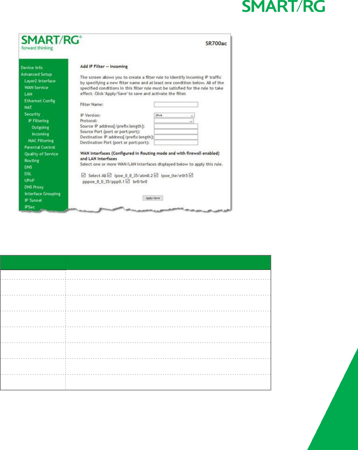
IP Filtering - Incoming
On this page, you can add an incoming filter when refusal of data from the WAN to the LAN is desired.
Note: This option is not available in the SR515ac model.
1. In the left navigation bar, click Advanced Setup >Security >IP Filtering >Incoming and then click Add. The following page
appears.
SMARTRG INC. PROPRIETARY AND CONFIDENTIAL. ALL RIGHTS RESERVED. COPYRIGHT © 2017 55
2. Fill in the fields, using the information in the table below.
3. Click Apply/Save to commit your changes.
The fields on this page are explained in the following table.
Field Name Description
Filter Name A free-form text field. Enter a descriptive name for this filter.
IP Version Select the IP version for this filter. Options are IPv4 and IPv6. The default is
IPv4.
Protocol Select the protocol to be associated with this incoming filter. Options are:
TCP/UDP,TCP,UDP, or ICMP.
Source IP address [/pre-
fix length]
Enter the source IP address for rule. For IPv6, enter the prefix as well.
Source Port (port or
port:port)
Enter source port number or range (xxxxx:yyyyy).
Destination IP address
[/prefix length]
Enter the destination IP address for rule. For IPv6, enter the prefix as well.
Destination Port (port or
port:port)
Enter destination port number or range (xxxxx:yyyyy).
WAN Interfaces Select the WAN interfaces to which this rule will be applied. Options are Select
All or the interfaces defined for your network. The default is Select All.
SMARTRG INC. PROPRIETARY AND CONFIDENTIAL. ALL RIGHTS RESERVED. COPYRIGHT © 2017 56
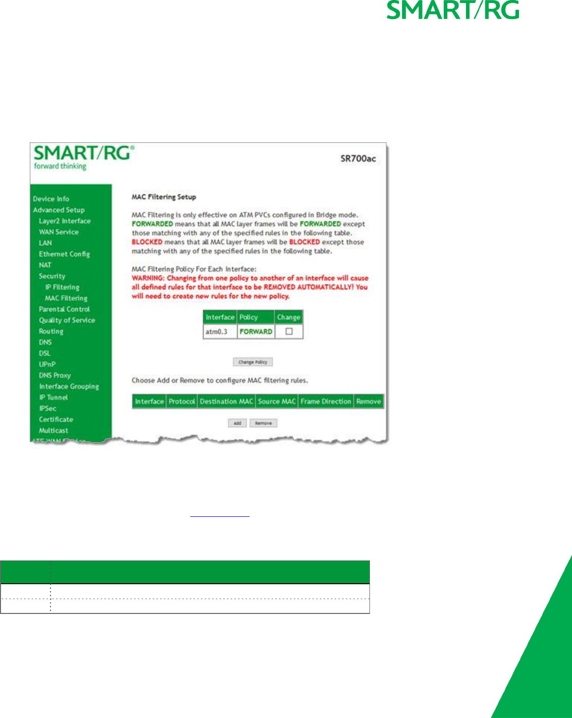
MAC Filtering
Your SmartRG gateway can block or forward packets based on the originating device. This MAC filtering feature is available only in
Bridge mode. For other modes, similar functionality is available via IP Filtering. On this page, you can manage MAC filtering for your
gateway.
1. In the left navigation bar, click Advanced Setup >Security >MAC Filtering. The following page appears.
2. To modify policy settings:
a. Review the information on the page.
b. Once you understand the consequences of changing the policy, click the Change checkbox, and then click Change
Policy. The policy is switched to FORWARD or BLOCKED.
3. To add a rule, follow the instructions in "MAC Filtering".
4. To remove a rule, click the Remove checkbox next to the rule and click the Remove button.
The fields on this page are explained in the following table.
Field Name Description
Interface The interface associated with an established policy rule.
Policy The policy type that is currently active. Options are FORWARD and BLOCKED.
SMARTRG INC. PROPRIETARY AND CONFIDENTIAL. ALL RIGHTS RESERVED. COPYRIGHT © 2017 57
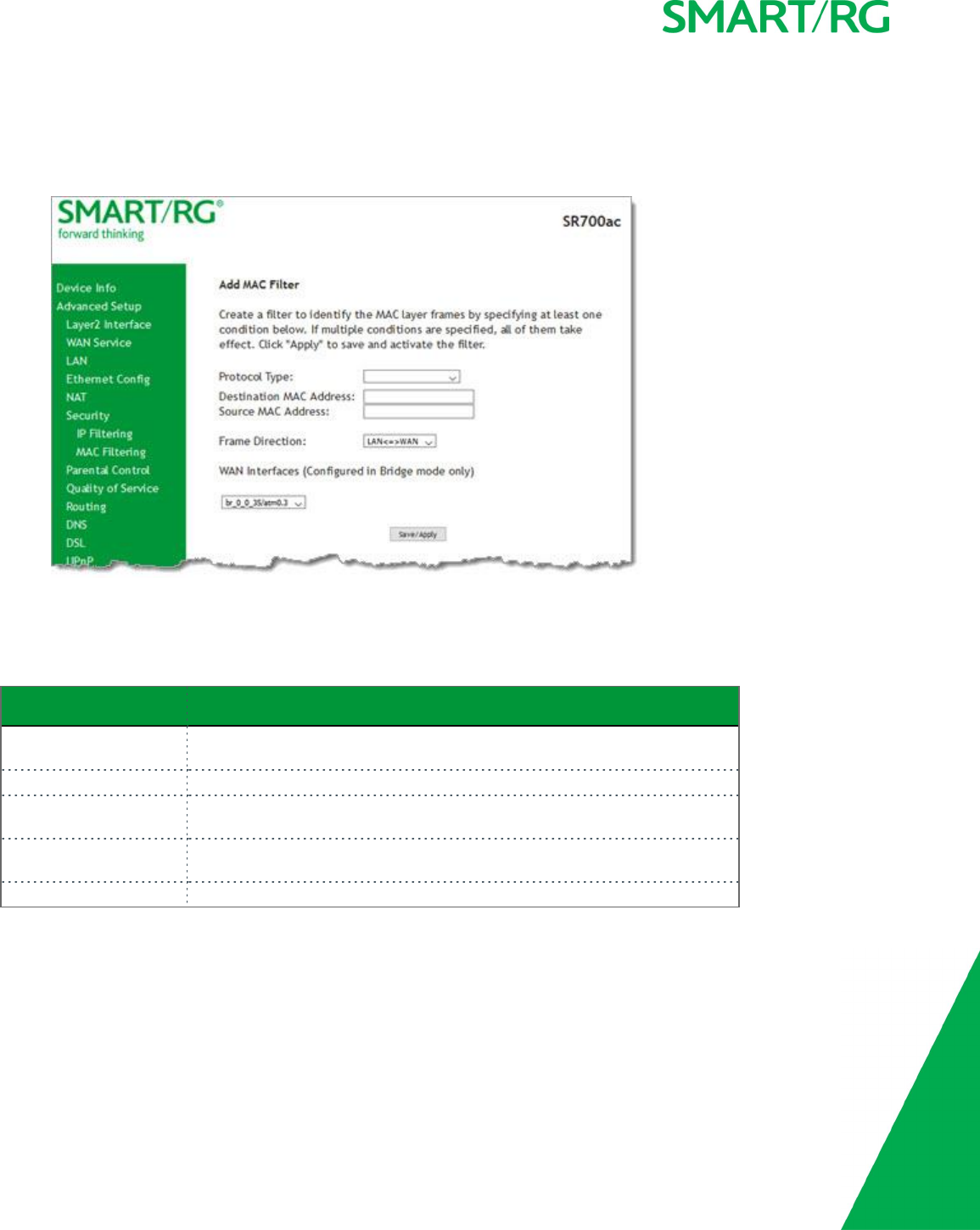
Add a MAC Filtering Rule
You cannot edit rules but you can add new ones and then remove the obsolete ones.
1. On the MAC Filtering page, click Add. The following page appears.
2. Fill in the fields, using the information provided in the following table.
3. Click Apply/Save to commit your changes.
The fields on this page are explained in the following table.
Field Name Description
Protocol Type Select the protocol associated with the device at the destination MAC
address. Options are PPPoE,IPv4,IPv6,AppleTalk,IPX,NetBEUI, and IGMP.
Destination MAC Address Enter the MAC address of the hardware you wish to associate with this filter.
Source MAC Address Enter the MAC address of the device that is originating requests intended for
the device associated with the Destination MAC address.
Frame Direction Select the incoming/outgoing packet interface. Options are LAN<=>WAN,
WAN=>LAN, and LAN=>WAN. The default is LAN <=> WAN.
WAN Interfaces Select the interface to which this filter is applied.
Parental Control
In this section, you can configure the Parental Control features of your SmartRG gateway to restrict Internet access to certain hours
and to certain URLS.
SMARTRG INC. PROPRIETARY AND CONFIDENTIAL. ALL RIGHTS RESERVED. COPYRIGHT © 2017 58
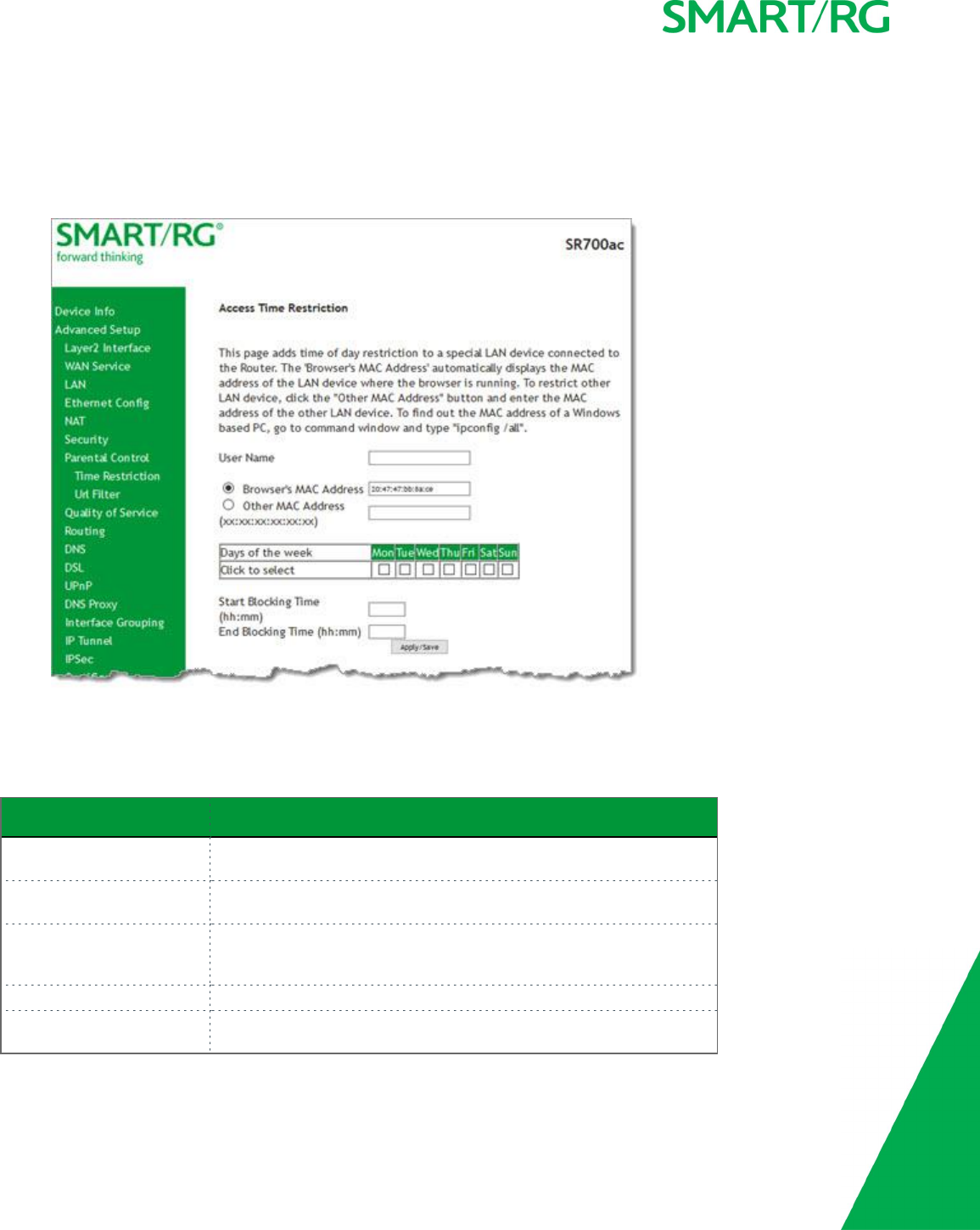
Time Restriction
On this page, you can restrict Internet access to particular days and specific times for each device that accesses your gateway.
1. In the left navigation bar, click Advanced Setup >Parental Control >Time Restriction and then click Add. The following
page appears.
2. Fill in the fields using the information in the table below.
3. Click Apply/Save.
The fields on this page are explained in the following table.
Field Name Description
User Name Enter a descriptive name for this restriction. This is a free-form text
field.
Browser's MAC Address The MAC address of the connected device. This option is selected by
default.
Other MAC Address Select this option to restrict access to another device. You can view a
list of the connected devices and MAC addresses on the Device Info >
ARP page.
Days of the week Select the days (Mon -Sun) for which the restrictions apply.
Start Blocking Time / End
Blocking Time
Enter the range of time that the devices listed above are restricted
from access to the Internet. Use 24-hour clock notation (00:00 -24:00).
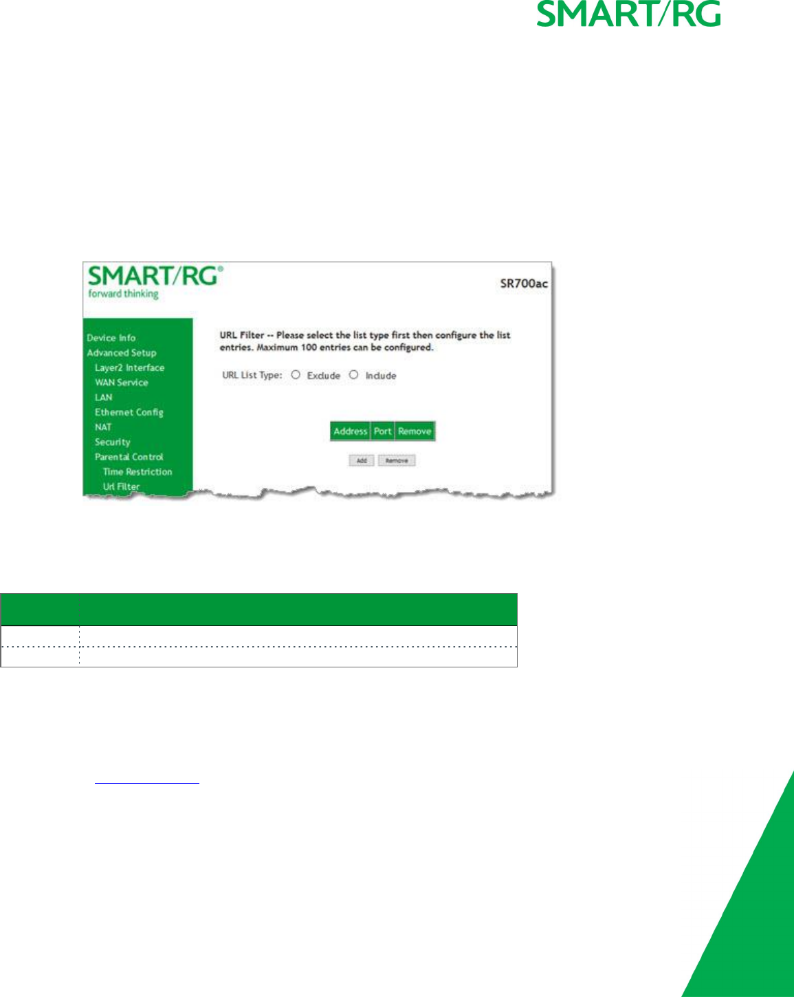
SMARTRG INC. PROPRIETARY AND CONFIDENTIAL. ALL RIGHTS RESERVED. COPYRIGHT © 2017 59
URL Filter
On this page, you can exclude and include URLs as desired to control access to them. Each list can include up to 100 addresses.
Note: Only one Exclude list and one Include list are supported for each gateway. Unique lists are not supported for connecting
devices.
1. In the left navigation bar, click Advanced Setup >Parental Control >Url Filter.
2. To block a URL:
a. Select Exclude List.
b. Click Add. The following page appears.
c. Click Apply/Save to save your settings. You are returned to the Url Filter page.
3. To create a list of URLs to allow, select Include and repeat the steps 2b and 2c.
The fields on this page are explained in the following table.
Field Name Description
URL Address Enter the URL address to be included in the list.
Port Number (Optional) Enter the port number associated with the URL. The default is 80.
Quality Of Service
Quality of Service (QoS) enables prioritization of Internet content to help ensure the best possible performance. This is particularly
useful for streaming video and audio content with minimized potential for drop-outs. QoS becomes significant when the sum of all
traffic (audio, vid"QoS Classification", data) exceeds the capacity of the line.
In this section, you can configure QoS settings including traffic queues, classifications (rules) and port shaping.
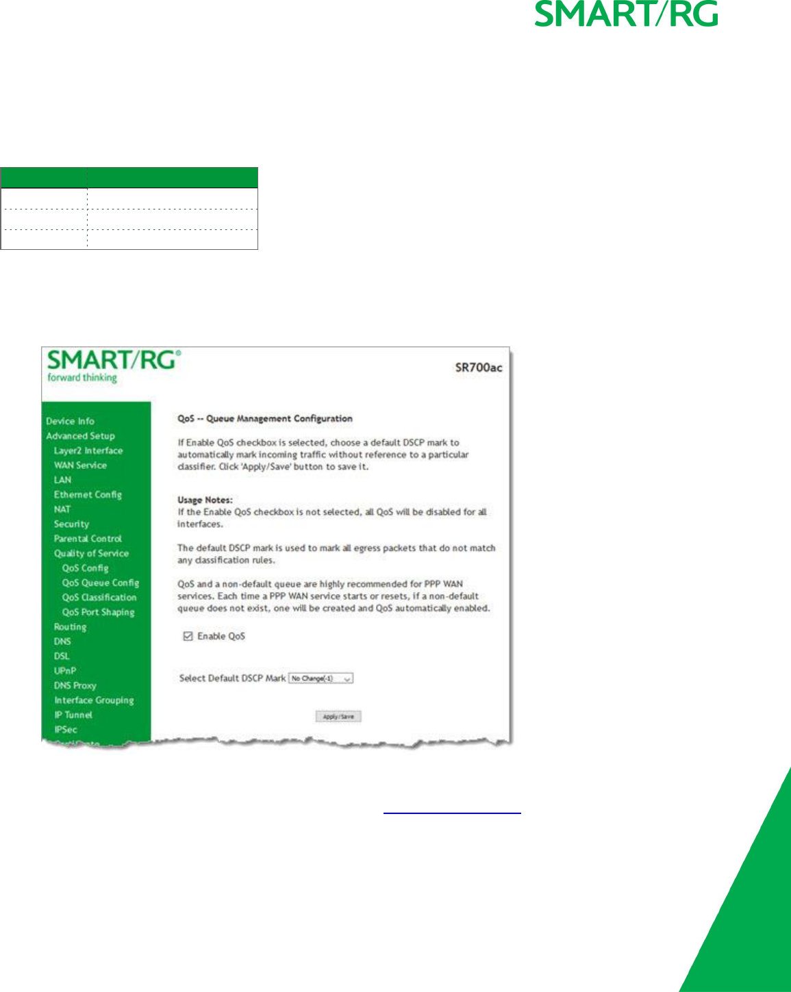
SMARTRG INC. PROPRIETARY AND CONFIDENTIAL. ALL RIGHTS RESERVED. COPYRIGHT © 2017 60
QoS Config
On this page, you can enable QoS and set the DSCP Mark classification.
The maximum number of queues that can be configured vary by mode, as shown below.
Mode Maximum # of queues
ATM 16
Ethernet 4 per interface
PTM 8
Note: Wireless queues (e.g., the WMM Voice Priority queue) are shown only when wireless is enabled. If the WMM Advertise func-
tion on the Wireless Basic Setup page is disabled, assigning classifications to wireless traffic has no effect.
1. In the left navigation bar, click Advanced Setup >Quality Of Service >QoS Config. The following page appears. QoS is
enabled by default.
2. To disable this feature, click the Enable QoS checkbox.
3. (Optional) In the Select Default DSCP Mark field, select the default Differentiated Services Code Point (DSCP) Mark clas-
sification value to be used. For a list of supported values, see "Supported DSCP Values". The default is No Change(-1).
Warning: If this option was already enabled and you clear the checkbox, QoS will be disabled for ALL interfaces.
4. Click Apply/Save to save your settings.
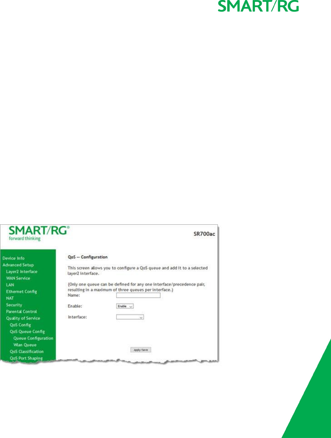
SMARTRG INC. PROPRIETARY AND CONFIDENTIAL. ALL RIGHTS RESERVED. COPYRIGHT © 2017 61
Supported DSCP Values
The DSCP marking QoS Queue Management Configuration marking on ingress packets is based on the selection you make in the Select
Default DSCP Mark field. The selected default marking is applied automatically to all incoming packets without reference to a par-
ticular classification.
Note: A default DSCP mark value of Default(000000) will mark all egress packets that do NOT match any classification.
The following values are supported. For more information about commonly used DSCP values, refer to RFC 2475.
No Change(-1) CS1(001000) AF32(011100) CS4(100000)
Auto Marking(-2) AF23(010110) AF31(011010) EF(101110)
Default(000000) AF22(010100) CS3(011000) CS5(101000)
AF13(001110) AF21(010010) AF43(100110) CS6(110000)
AF12(001100) CS2(010000) AF42(100100) CS7(111000)
AF11(001010) AF33(011110) AF41(100010)
QoS Queue Config
On this page you can configure a queue and add it to a selected Layer2 interface.
1. In the left navigation bar, click Advanced Setup >Quality Of Service >QoS Queue Config and then click Add. The following
page appears.
2. In the Name field, enter a brief descriptive name for this queue.

SMARTRG INC. PROPRIETARY AND CONFIDENTIAL. ALL RIGHTS RESERVED. COPYRIGHT © 2017 62
3. In the Interface field, select the Layer 2 interface to be associated with this queue. Options include Dynamic WAN and the
interfaces defined for your gateway. When you select an interface, additional fields appear. If you select Dynamic WAN,
they appear once for each defined WAN interface.
4. Fill in the other fields, using the information in the table below.
5. Click Apply/Save to save your settings.
The fields on this page are explained in the following table.
Field Name Description
Name Enter a descriptive name for this configuration. This is a free-form text field.
Enable Select to enable or disable a given QoS queue configured on the selected inter-
face.
Note: Only one queue can be defined for any one interface/precedence pair,
resulting in a maximum of three queues per interface.
Queue Precedence Select the priority value to be associated with QoS queue defined. Options
include levels for SP and SP|WRR|WFQ.
Note: Lower value = higher priority.
Scheduler Algorithm (Appears when you select SP|WRR|WFQ in the Queue Precedence field)
Select an algorithm for data priority in queues. Options are:
lStrict Priority: Allows shaping of rate and burst size for packets in
queue.
lWeighted Round Robin: Applies a fair round robin scheme weighting
that is effective for networks with fixed packet sizes, e.g., ATM net-
works.
lWeighted Fair Queuing: Applies a fair queuing weighting scheme via
allowing different sessions to have different service shares for
improved data packets flow in networks with variable packet size, e.g.,
PTM/IP networks.
The following options appear only when the Queue Precedence field is set to SP|WRR|WFQ and the
Scheduler Algorithm field is set to Strict Priority.
Minimum Rate Enter the minimum shaping rate for packets in QoS queues. Options are 1-
100000 Kbps.
To specify no minimum shaping, enter -1.
Shaping Rate Enter the shaping rate for packets in QoS queues. Options are 1-100000 Kbps.
To specify no minimum shaping, enter -1.
Shaping Burst Size Enter the shaping burst size to be applied to packets in the defined queue.
Options are 1600 bytes or greater.
Queue Weight (Appears when you select either of the Weighted options in the Scheduler
Algorithm field) Enter a weight for prioritizing this queue. Options are 1-63.
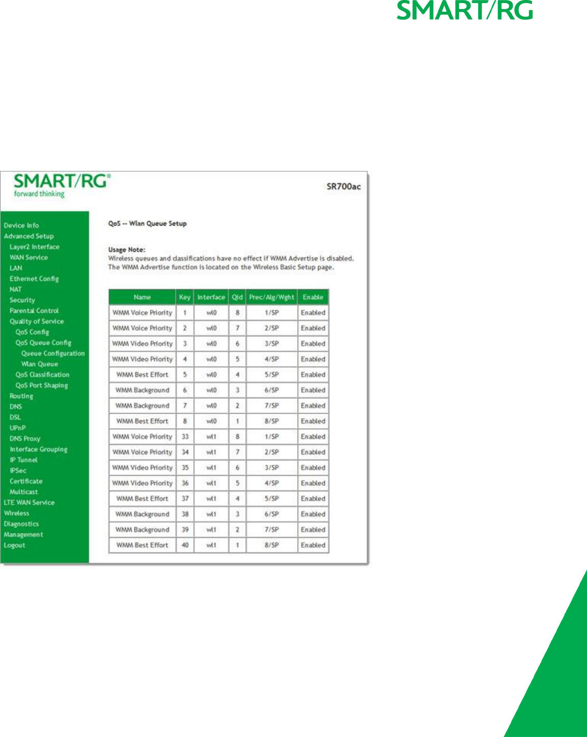
SMARTRG INC. PROPRIETARY AND CONFIDENTIAL. ALL RIGHTS RESERVED. COPYRIGHT © 2017 63
WLAN Queue
On this page, you can view the wireless queues and classifications.
Note: The WMM Advertise option must be enabled before these classifications will function. This option is enabled by default. If you
have disabled it, go to the Wireless > Basic page and clear the Disable WMM Advertise checkbox.
In the left navigation bar, click Advanced Setup >Quality Of Service >QoS Queue Config >Wlan Queue. The following page
appears.
QoS Classification
On this page, you can create traffic class rules for classifying the ingress traffic into a priority queue. You can also mark the DSCP or
Ethernet priority of the packet.
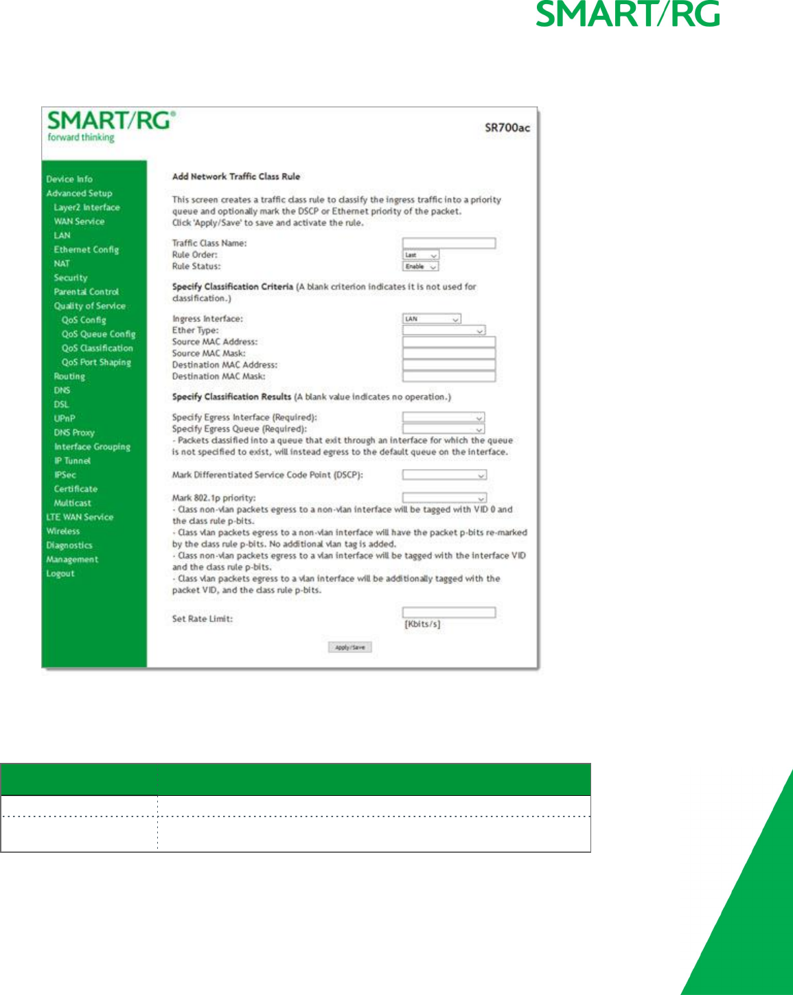
SMARTRG INC. PROPRIETARY AND CONFIDENTIAL. ALL RIGHTS RESERVED. COPYRIGHT © 2017 64
1. In the left navigation bar, click Advanced Setup >Quality Of Service >QoS Classification and then click Add. The following
page appears. A maximum of 32 entries can be configured.
2. Fill in the fields, using the information in the table below.
3. Click Apply/Save to commit your changes.
The fields on this page are explained in the following table.
Field Name Description
Traffic Class Name Enter a descriptive name for this rule. This is a free-form text field.
Rule Order Select whether this rule is processed next or last in the list of classification
rules. The only option is Last and cannot be changed.

SMARTRG INC. PROPRIETARY AND CONFIDENTIAL. ALL RIGHTS RESERVED. COPYRIGHT © 2017 65
Field Name Description
Rule Status Select whether this rule is active or inactive. Options are: Enable and Dis-
able. The default is Enable.
Specify Classification Criteria section
Ingress Interface Select an interface. Options are LAN,WAN and any interface already con-
figured for your gateway.
Ether Type Select the Ethernet interface type for this classification. Options include:
IP,ARP,IPV6,8855,8856,and 8021Q.
Source MAC Address
Source MAC Mask
Enter the source MAC address and mask for this classification.
Destination MAC Address
Destination MAC Mask
Enter the destination MAC address and mask for this classification.
Source IP Address/Mask
Vendor Class ID
User Class ID
(Appear when you select IP or IPv6 in the Ether Type field) Select an
option and enter the appropriate value, i.e, the source IP address and
Source IP mask, vendor class ID, or user class ID.
Destination IP
Address/Mask
Enter the destination IP Address and Mask for this classification.
Differentiated Service
Code Point (DSCP) Check
Select the DSCP code that must be present in the queue identifiers.
Protocol Enter the protocol specified for this classification. Options are TCP,UDP,
ICMP, and IGMP.
UDP/TCP Source Port (Appears when TCP or UDP is selected in the Protocol field) Enter the
source port for this classification. You can enter a single port or a range of
ports (port:port).
UDP/TCP Destination Port (Appears when TCP or UDP is selected in the Protocol field) Enter the des-
tination port for this classification. You can enter a single port or a range of
ports (port:port).
802.1p Priority Check (Appears when 8021Q is selected in the Ether Type field) Select priority
level. Options are 1 - 7.
Specify Classification Results section
Specify Egress Interface Select the egress interface for this rule. Options are the interfaces already
configured.
Specify Egress Queue Select the egress queue for this rule. Options are the queues already con-
figured.
Mark Differentiated Ser-
vice Code Point
Select the desired DSCP code.
Mark 802.1P priority This value is inserted into the Ethernet frame and used to differentiate
traffic. Lower values assign higher priorities. Options are: 1-7.
Set Rate Limit (Kbps) Enter the data traffic rate limit applied for this classification.
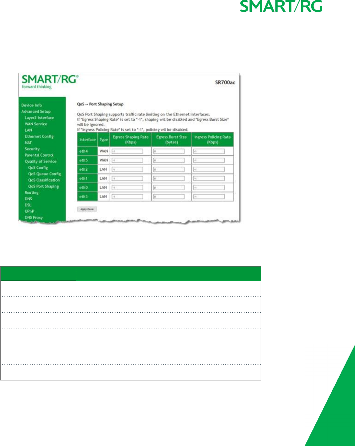
SMARTRG INC. PROPRIETARY AND CONFIDENTIAL. ALL RIGHTS RESERVED. COPYRIGHT © 2017 66
QoS Port Shaping
QoS Port Shaping facilitates setting a fixed rate (Kbps) for each of the Ethernet ports.
1. In the left navigation bar, click Advanced Setup >Quality Of Service >QoS Port Shaping. The following page appears.
2. Fill in the fields, using the information in the table below.
3. Click Apply/Save to commit your changes.
The fields on this page are explained in the following table.
Field Name Description
Interface Each entry in this column represents one of the Ethernet LAN ports on
the gateway.
Type Each entry in this column identifies the function for which each physical
port is configured on the gateway.
Egress Shaping Rate (Kbps) Enter the data rate for packets on the specified Interface. Options are:
1-1,000,000 Kbps. The default is -1 (no shaping).
Egress Burst Size (bytes Enter the burst size to be applied to packets in the defined queue.
Options are 1600 bytes or greater. The default is 0(no size limit).
If you enter a value of -1 (disabled) in the Egress Shaping Rate field, the
value in this field is ignored.
Ingress Policing Rate (Kbps) Enter data rate for policing incoming packets in the defined queue. The
default is -1 (no policing).
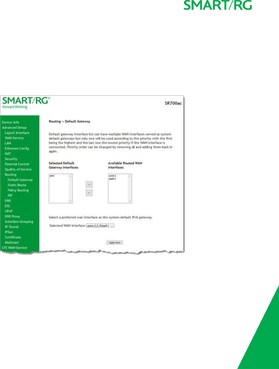
SMARTRG INC. PROPRIETARY AND CONFIDENTIAL. ALL RIGHTS RESERVED. COPYRIGHT © 2017 67
Routing
In this section, you can configure default gateways, static routing, policy routing and RIP settings.
Default Gateway
On this page, you can configure the default gateway interface list to establish access priority, that is, iInterfaces are accessed in the
order listed in the Selected Default Gateway Interfaces column.
1. In the left navigation bar, select Advanced Setup >Routing. The following page appears.
2. Select the interfaces that you want used as default gateway interfaces. Click the arrows to move your selection between the
columns. Move the highest priority interface first, followed by the next highest priority interface, and so on.
3. (Optional) In the Selected WAN Interface field, select an IPv6 interface. You must configure the IPv6 interface before it
appears in this field.
4. Click Apply/Save to commit your changes.
Static Route
On this page, you can configure static routes for your network. A static route is a manually configured, fixed route for IP data. You
can enter a maximum of 32 entries.
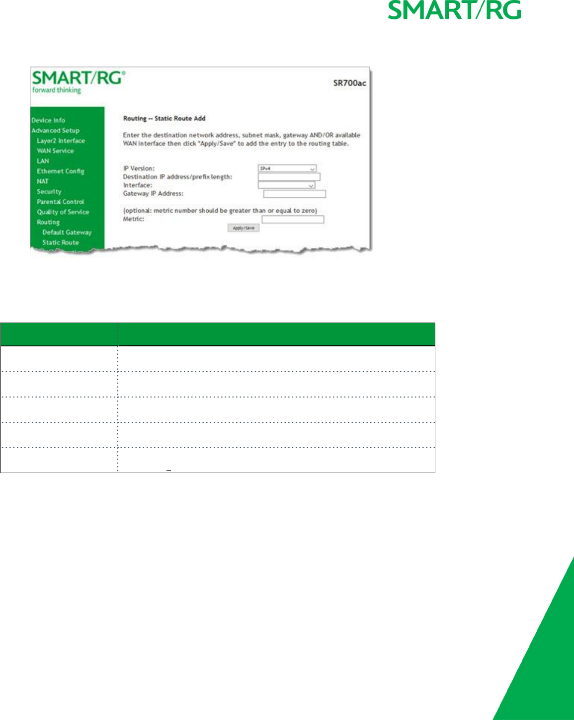
SMARTRG INC. PROPRIETARY AND CONFIDENTIAL. ALL RIGHTS RESERVED. COPYRIGHT © 2017 68
1. In the left navigation bar, click Advanced Setup >Routing >Static Route and then click Add. The following page appears.
2. Fill in the fields, using the information in the table below.
3. Click Apply/Save to commit your changes.
The fields on this page are explained in the following table.
Field Name Description
IP Version Select the IP version associated with the static route you wish to create.
Options are: IPv4 and IPv6.
Destination IP address/-
prefix length
Enter the destination network address / subnet mask for route.
Interface Select the WAN Interface for this route. This list filtered by the selected IP
version.
Gateway IP Address Enter the destination IP address for this route. If needed, include the /prefix
length.
Metric (Optional) Establishes traffic priority/weighting. Must be equal to or greater
than zero (>0).
Policy Routing
Policy routing makes somewhat automated routing choices based on policies defined by a network administrator. For example, a net-
work administrator might want to deviate from standard routing based on destination markers in the packet and, instead, forward a
packet based on the source address.
On this page, you can configure similar policies.
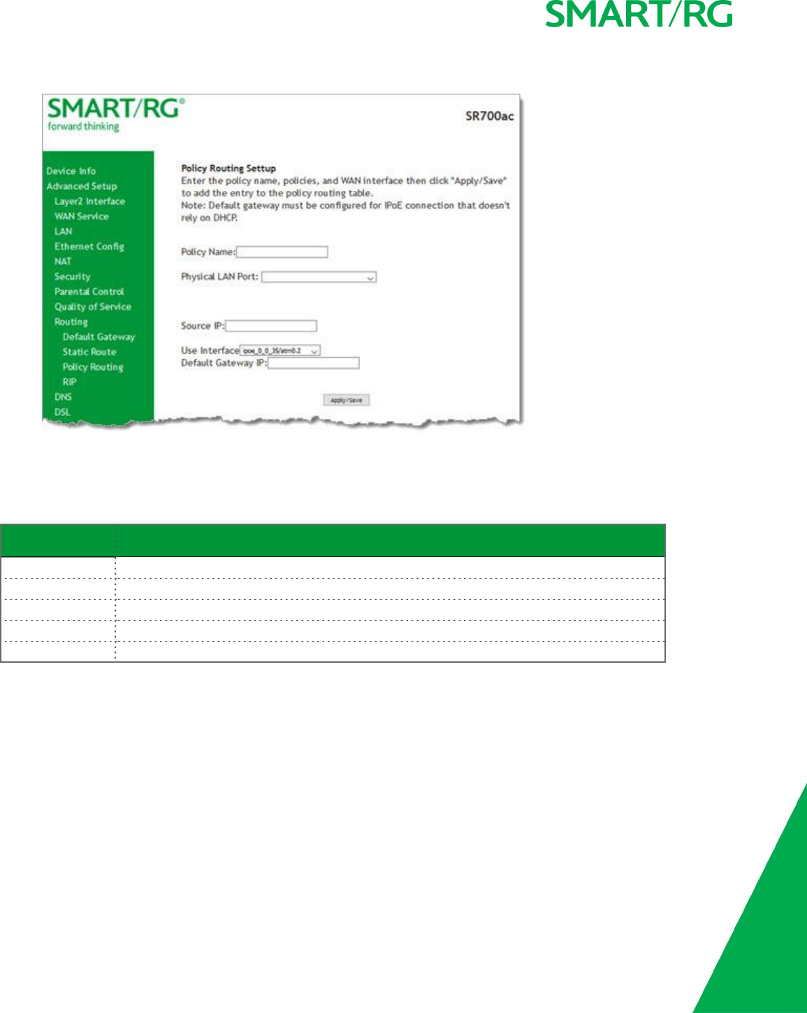
SMARTRG INC. PROPRIETARY AND CONFIDENTIAL. ALL RIGHTS RESERVED. COPYRIGHT © 2017 69
1. In the left navigation bar, click Advanced Setup >Routing >Policy Routing and then click Add. The following page appears.
2. Fill in the fields, using the information in the table below.
3. Click Apply/Save to commit your changes.
The fields on this page are explained in the following table.
Field Name Description
Policy Name Enter a descriptive name for this entry to the policy routing table. This is a free-form text field.
Physical LAN Port Select a physical LAN interface for the policy route.
Source IP Enter the IP address for the source of this policy route.
Use Interface Select the WAN Interface for this policy route.
Default Gateway IP Enter the IP address of the default gateway.
RIP (Routing Information Protocol)
RIP is a type of distance-vector routing protocol, which leverages hop count as a metric for routing. RIP puts a limit on the number of
hops (maximum of 15) allowed in order to prevent routing loops. This can sometimes limit the size of networks where RIP can be suc-
cessfully employed.
On this page, you can configure the RIP settings.
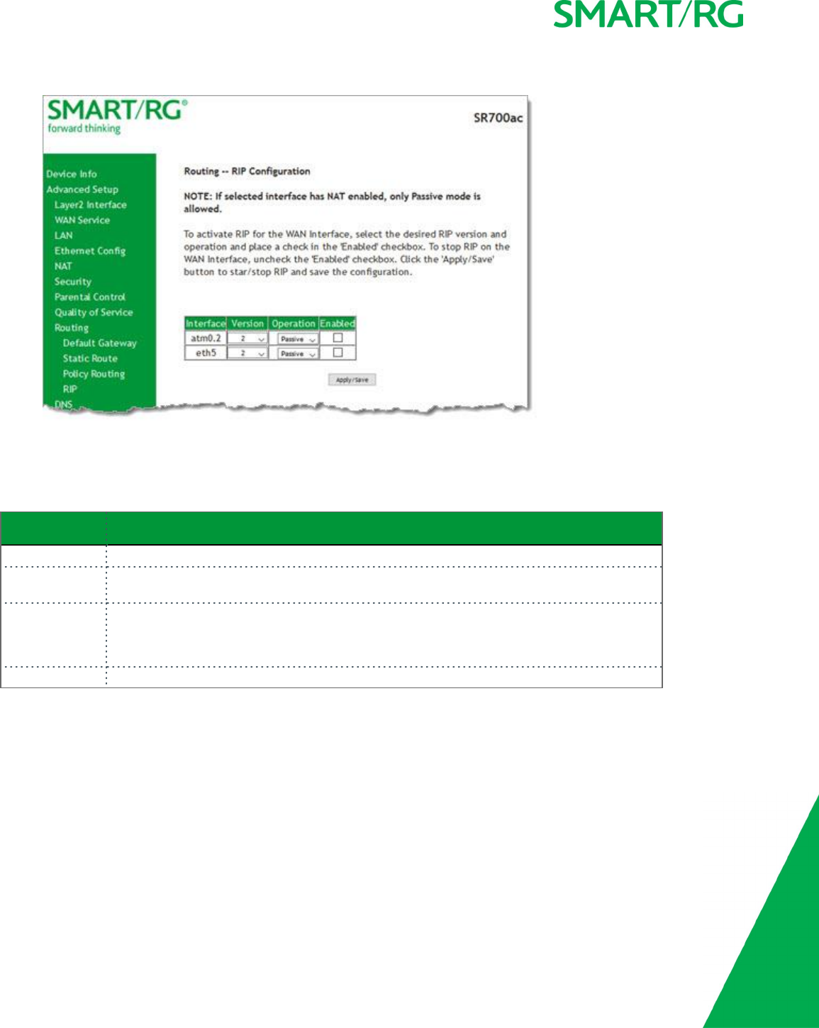
SMARTRG INC. PROPRIETARY AND CONFIDENTIAL. ALL RIGHTS RESERVED. COPYRIGHT © 2017 70
1. In the left navigation bar, click Advanced Setup >Routing >RIP, and then click Add. The following page appears.
2. Fill in the fields, using the information in the table below.
3. Click Apply/Save to commit your changes.
The fields on this page are explained in the following table.
Field Name Description
Interface Available WAN interfaces.
Version Select the applicable Routing Interface Protocol version. Options are: 1,2, and Both. The
default is 2.
Operation Select the operation mode. Options are:
lActive: This mode listens and advertises routes.
lPassive: This mode listens only. It does not advertise routes. This is the default.
Enabled Click the checkbox to employ RIP on the displayed interface.
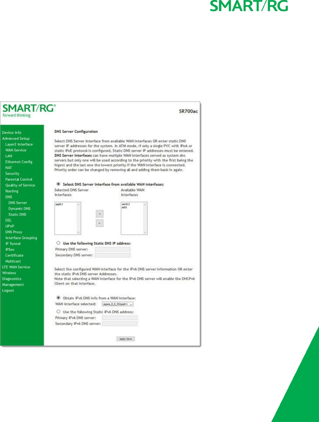
SMARTRG INC. PROPRIETARY AND CONFIDENTIAL. ALL RIGHTS RESERVED. COPYRIGHT © 2017 71
DNS
In this section, you can configure a DNS server, dynamic DNS and static DNS.
DNS Server
On this page, you can input the Domain Name Server (DNS) information supplied by your service provider.
1. In the left navigation bar, click Advanced Setup >DNS. The following page appears.
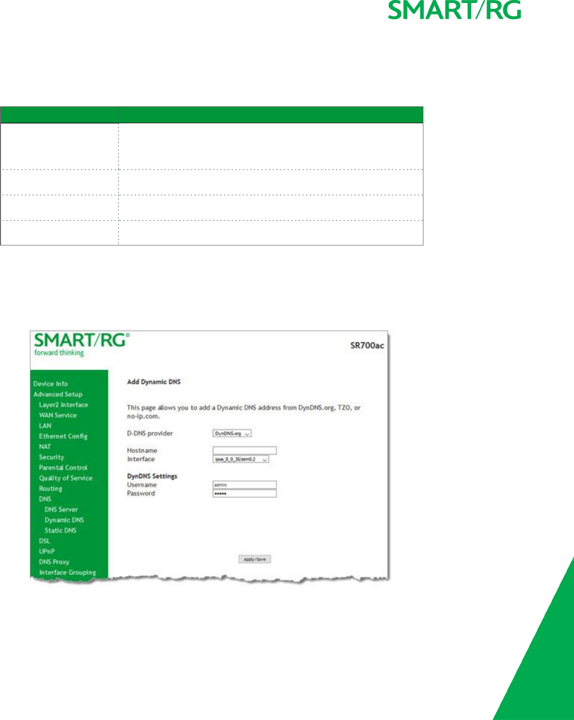
SMARTRG INC. PROPRIETARY AND CONFIDENTIAL. ALL RIGHTS RESERVED. COPYRIGHT © 2017 72
2. Modify the settings as needed, using the information supplied by your provider and that supplied in the table below.
3. Click Apply/Save.
The fields on this page are explained in the following table.
Field Name Description
Select DNS Server Interface
from available WAN inter-
faces
Select entries in the Selected DNS Server Interfaces and Available WAN
Interfaces columns and click the arrows to move them left or right. At
least one entry must remain in the Selected DNS Server Interfaces
column.
Use the following Static DNS
IP address
Click to use static DNS IP addresses. Then, enter the IP addresses of the
primary and secondary DNS servers.
Obtain IPv6 DNS info from a
WAN interface
This option is selected by default. Change the value in the WAN Interface
selected field only for IPv6 environments.
Use the following Static
IPv6 DNS IP address
Click to use static DNS IP addresses. Then, enter the IP addresses of the
primary and secondary IPv6 DNS servers.
Dynamic DNS
Dynamic DNS (DDNS) automatically updates a name server in the DNS with the active DNS configuration of its configured hostnames,
addresses or other data. Often this update occurs in real time. On this page, you can configure the settings for this feature.
1. In the left navigation bar, click Advanced Setup >DNS >Dynamic DNS and then click Add. The following page appears.
2. Enter your desired settings.
3. Click Apply/Save to commit your changes.
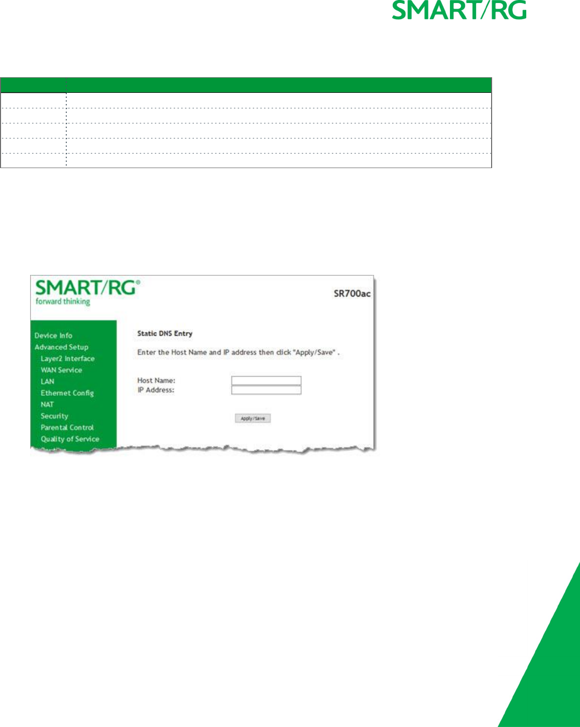
SMARTRG INC. PROPRIETARY AND CONFIDENTIAL. ALL RIGHTS RESERVED. COPYRIGHT © 2017 73
The fields on this page are explained in the following table.
Field Name Description
D-DNS provider Select a dynamic Domain Name Server provider.
Hostname Enter the hostname of the dynamic DNS server.
Interface Select the gateway WAN interface whose traffic will be pointed at the specified Dynamic DNS provider.
Username Enter the username for the dynamic DNS server.
Password Enter the password for the dynamic DNS server.
Static DNS
The Static DNS service allows you to resolve DNS queries on the Broadband Router by adding a static host name to the IP Address
mappings.
On this page, you can configure up to 10 static DNS entries.
1. In the left navigation bar, click Advanced Setup >DNS >Static DNS and then click Add. The following page appears.
2. In the Host Name field, enter the name of the client computer.
3. In the IP Address field, enter the IP address of the DNS server client used to assist in resolving domain names.
4. Click Apply/Save to commit your changes.

SMARTRG INC. PROPRIETARY AND CONFIDENTIAL. ALL RIGHTS RESERVED. COPYRIGHT © 2017 74
DSL
On this page, you can configure settings for the DSL interface.
Caution: Altering these settings unnecessarily can result in the gateway being unable to attain DSL synchronization.
1. In the left navigation bar, click Advanced Setup >DSL. The following page appears.
2. Modify the fields as needed.
3. Click Apply/Save to commit your changes.

SMARTRG INC. PROPRIETARY AND CONFIDENTIAL. ALL RIGHTS RESERVED. COPYRIGHT © 2017 75
The fields on this page are explained in the following table.
Modulation Data Transmission Rate Max Downstream
(Mbps)
Max
Upstream
(Mbps)
G.Dmt ITU-T G.992.1 standard. 12 1.3
G.lite ITU-T G.991.2 standard. 4 0.5
T1.413 ANSI T1.413 Issue 2 standard. 8 1.0
ADSL2 ITU-T G.992.3 standard. 12 1.0
AnnexL Annex L of ITU-T G.992.3 standard which supports longer loops but with
reduced transmission rates.
ADSL2+ ITU-T G.992.5 standard. 28 1.0
AnnexM Annex L of ITU-T G.992.5 standard which supports extended upstream
bandwidth.
24 3
VDSL2 ITU-T G.993.2 standard. 100 60
The following table explains the maximum transaction power for each profile supported for SRG gateways.
Parameter 8a 8b 8c 8d 12a 12b 17a
Max DS Tx Power (dBm) +17.5 +20.5 +11.5 +14.5
Max US Tx Power (dBm) +14.5
Min bidirectional net data rate 50Mbps 68Mbps 100Mbps

SMARTRG INC. PROPRIETARY AND CONFIDENTIAL. ALL RIGHTS RESERVED. COPYRIGHT © 2017 76
UPnP
On this page, you can enable UPnP when 3rd party devices on your LAN support this Universal Plug and Play standard. Common cli-
ent devices include gaming consoles, IP cameras, printers and others. This feature is enabled by default.
1. In the left navigation bar, select Advanced Setup >UPnP. The following page appears.
2. To disable this option, click Enable UPnP to clear the box.
3. Click Apply/Save to commit your changes.
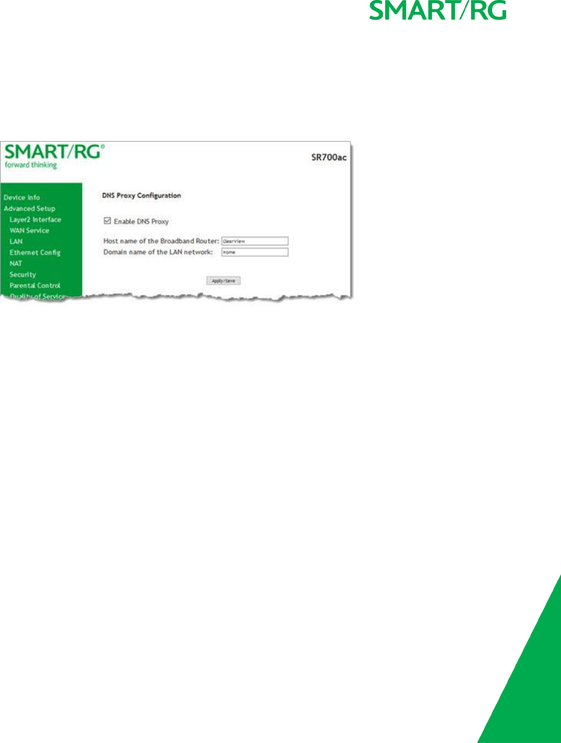
SMARTRG INC. PROPRIETARY AND CONFIDENTIAL. ALL RIGHTS RESERVED. COPYRIGHT © 2017 77
DNS Proxy
On this page, you can configure the DNS proxy settings. A DNS proxy improves domain look-up performance for clients by creating a
historical cache of look-ups.
1. In the left navigation bar, click Advanced Setup >DNS Proxy. The following page appears. This feature is enabled by default.
2. To disable the DNS proxy feature, click the Enable DNS Proxy checkbox to clear it. The Host name and Domain Name fields
are hidden.
3. Click Apply/Save to commit your changes.

SMARTRG INC. PROPRIETARY AND CONFIDENTIAL. ALL RIGHTS RESERVED. COPYRIGHT © 2017 78
Interface Grouping
On this page, you can create an interface group to map local interfaces to WAN interfaces. A typical application for this feature is
assigning IPTV set-top boxes to a WAN interface.
1. In the left navigation bar, click Advanced Setup >Interface Grouping and then click Add (below the table). The following
page appears. (The instructions that display at the top of this page are not shown below).
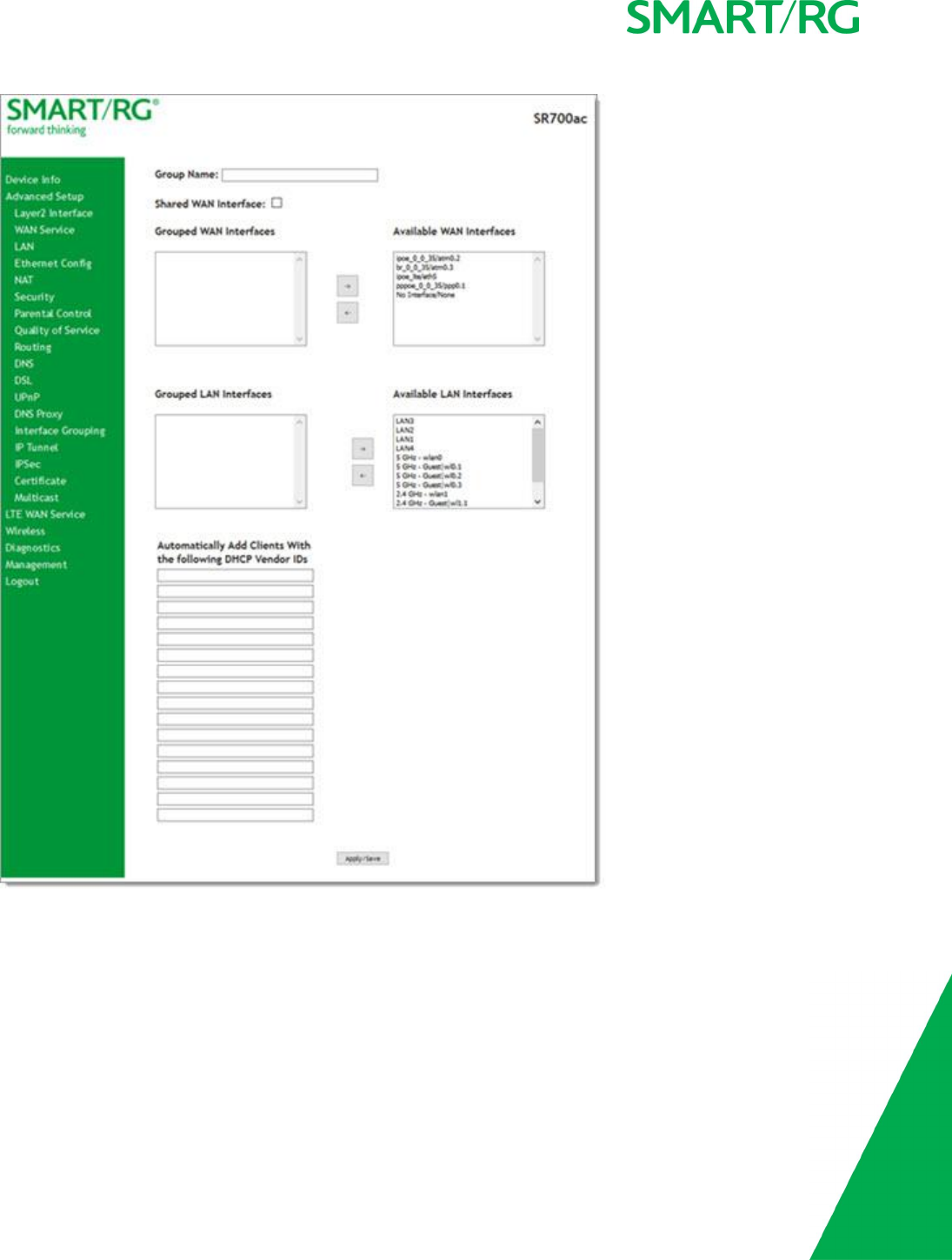
SMARTRG INC. PROPRIETARY AND CONFIDENTIAL. ALL RIGHTS RESERVED. COPYRIGHT © 2017 79
2. To create a new interface group, enter a unique Group Name, then proceed with either step 3 (dynamic) or step 4 (static)
below.
3. If this new grouped interface is to share the WAN interface, click Shared WAN Interface.Not selecting this option this will
cause the WAN interface you select to be removed from any other interface groups.
Important: If a vendor ID is configured for a specific client device, make sure to reboot the client device attached to the gate-
way to allow it to obtain an appropriate IP address.
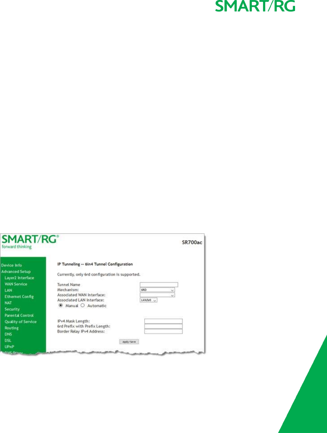
SMARTRG INC. PROPRIETARY AND CONFIDENTIAL. ALL RIGHTS RESERVED. COPYRIGHT © 2017 80
4. In the Available WAN Interfaces list, select the interface(s) that you want to group and click the left arrow to move it to the
Grouped WAN Interfaces list. Hold down the CTRL key or Shift key to select multiple interfaces.
Note: Depending on the WAN interface configuration, these clients may obtain public IP addresses.
5. Do the same in the Grouped and Available LAN Interfaces lists for any applicable LAN interfaces.
6. To automatically add LAN clients (such as set-top boxes) to a WAN Interface in the new group, enter the DHCP vendor ID
string. You can add up to 16 vendor IDs.
When you configure a DHCP vendor ID string, any DHCP client request that includes this vendor ID is denied an IP address
from the local DHCP server (DHCP option 60).
7. Click Apply/Save. Your changes take effect immediately.
8. To remove a grouping, select the grouping and click Remove. You can only remove groupings that you create.
IP Tunnel
IP Tunneling is typically used as a means to establish a path between two independent networks. Your SmartRG gateway supports
connecting islands of IPv6 networks across the IPv4 internet or IPv4 in IPv6 as well.
In this section, you can configure IP tunnel settings.
Note: For IPv6inIPv4, only 6rd configuration is supported. For IPv4inIPv6, only DS-Lite configuration is supported.
IPv6inIPv4
On this page, you can configure the IPv6inIP4 settings.
1. In the left navigation bar, click Advanced Setup >IP Tunnel >IPv6inIPv4 and then click Add. The following page appears.
2. Enter a Tunnel Name.
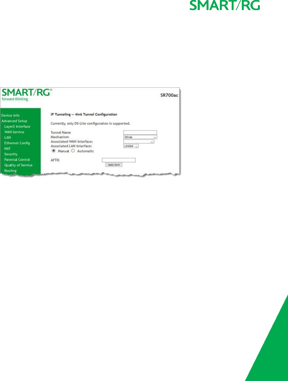
SMARTRG INC. PROPRIETARY AND CONFIDENTIAL. ALL RIGHTS RESERVED. COPYRIGHT © 2017 81
3. Select the WAN and LAN interfaces associated with the tunnel you wish to establish. The Manual button is selected by
default.
4. Enter the appropriate values in the IPv4 Mask Length, 6rd Prefix with Prefix Length and Border Relay IPv4 Address fields.
5. Click Apply/Save to commit your changes.
IPv4inIPv6
On this page, you can configure the IPv4inIP6 settings.
1. In the left navigation bar, click Advanced Setup >IP Tunnel >IPv6inIPv4 and then click Add. The following page appears.
Note: Currently, only the DS-Lite mechanism is supported.
2. Enter a brief descriptive Tunnel Name.
3. Select the LAN and WAN interfaces associated with the tunnel you wish to establish.
4. In the AFTR field, enter the Address Family Transition Router remote address.
5. Click Apply/Save to commit your changes.
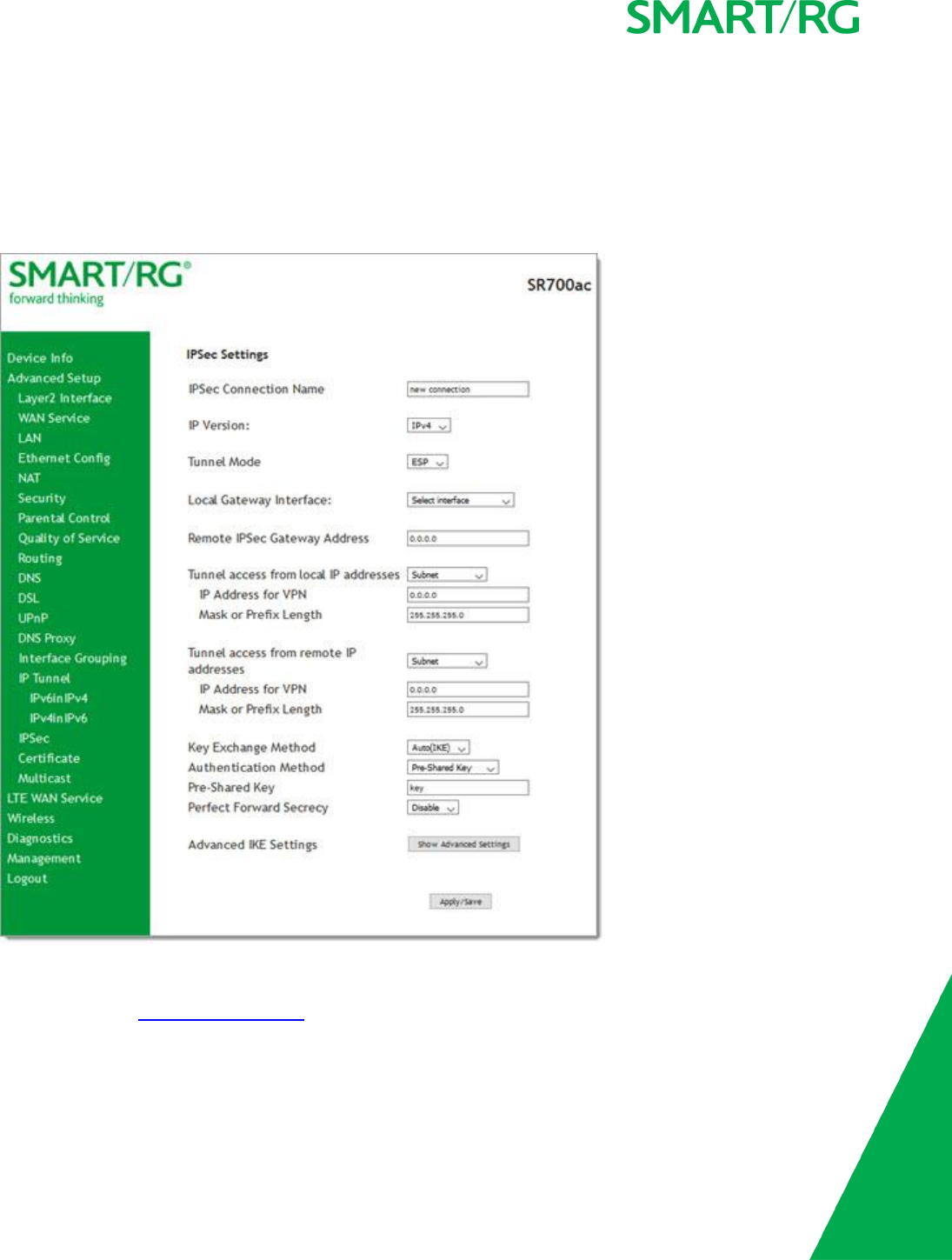
SMARTRG INC. PROPRIETARY AND CONFIDENTIAL. ALL RIGHTS RESERVED. COPYRIGHT © 2017 82
IPSec
Internet Protocol Security is a protocol for securing communications by packet level encryption and authentication.
On this page, you can enable and remove connections, or edit existing connections.
1. In the left navigation bar, click Advanced Setup >IP Sec and then click Add New Connection. The following page appears.
2. Enter your connection details by completing the appropriate fields.
3. If desired, click Advanced IKE Settings to select Phase 1 and Phase 2 specific parameters. For detailed information about
these settings, see "Advanced IKE Settings".
4. Click Apply/Save to commit your changes.
The fields on this page are explained in the following table.

SMARTRG INC. PROPRIETARY AND CONFIDENTIAL. ALL RIGHTS RESERVED. COPYRIGHT © 2017 83
Field Name Description
IPSec Connection Name A free form text field. Enter a descriptive name for this connection
IP Version Select the IP version environment associated with your infrastructure. Options are IPv4 and IPv6.
Tunnel Mode Select the encapsulation method to be used. Options are:
lESP: Use this mode to encapsulate a packet with ESP and IP headers. An ESP trailer is added to
the packet for authentication and integrity.
lAH: Use this mode to encapsulate a packet with AH and IP headers. For authentication, the
entire packet is signed.
Local Gateway Interface Select the WAN connection to be associated with this tunnel.
Remote IPSec Gateway
Address
Enter the WAN IP for this tunnel.
Tunnel Access From Local
IP Addresses
Select IP information for site A and B. Options are:
lSubnet: Allows access to the entire LAN.
lSingle Address: For single host, select this option.
IP Address for VPN Enter the IP address for local access.
Mask or Prefix Length Enter the subnet mask or prefix length for IP address entered for local access, e.g., 255.255.255.0.
Tunnel Access From
Remote IP Addresses
Select IP information for site A and B. Options are:
lSubnet: Allows access to the entire LAN.
lSingle Address: For single host, select this option.
IP Address for VPN Enter the IP address for remote access.
Mask or Prefix Length Enter the subnet mask or prefix length for IP address entered for remote access, e.g., 255.255.255.0.
Key Exchange Method The key-exchange method to be used for IPSec. Options are:
lAuto(IKE): This method uses the negotiated key-exchange method for IPSec. This is the default
and recommended for best results.
lManual: This method requires that you configure the details.
Authentication Method Select the method by which the remote end will authenticate. Options are:
lPre-Shared Key: A key is distributed to authorized users for logging into the system. Enter the
key in the Pre-shared Key field.
lCertificate (x.509): A certificate is used for authentication. Select the certificate file in the
Certificate field that appears.
Perfect Forward Secrecy This setting determines whether a session key derived from a set of long-term keys is compromised if
one of the long-term keys in the set is compromised.
lEnable: Prevents long-term key from being compromised.
lDisable: Permits long-term keys to be compromised.
Advanced IKE Settings
You can configure advanced IKE settings if desired.
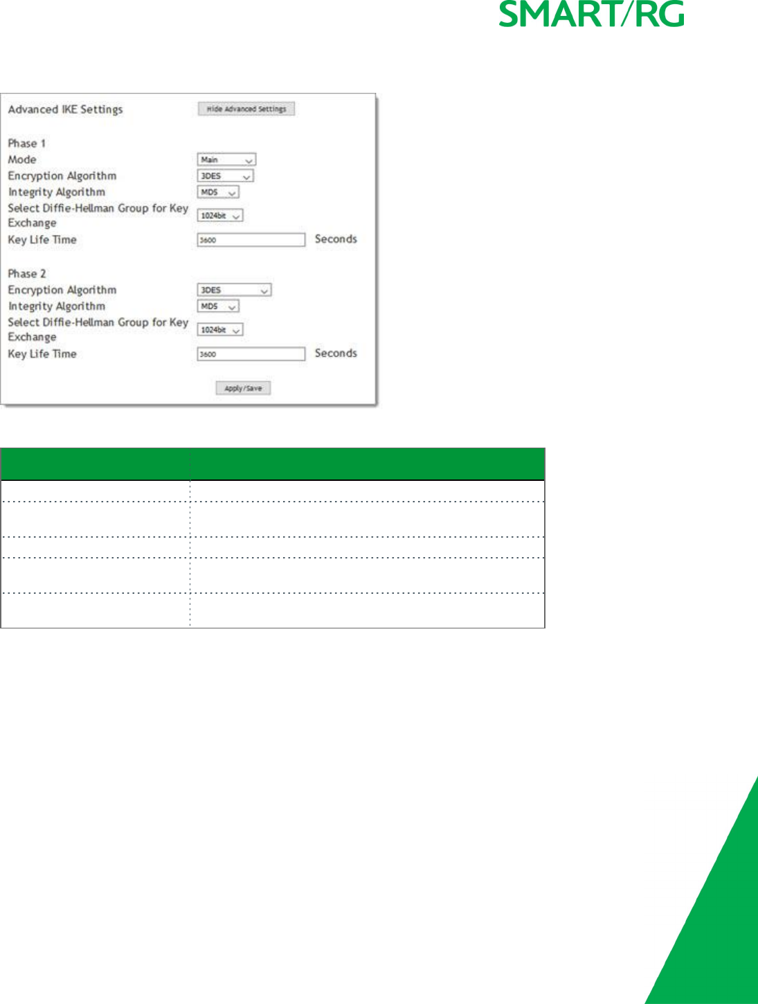
SMARTRG INC. PROPRIETARY AND CONFIDENTIAL. ALL RIGHTS RESERVED. COPYRIGHT © 2017 84
1. On the IPSec Settings page, click Show Advanced IKE Settings to display the Phase 1 and Phase 2 fields.
2. Fill in the fields, using the information in the table below.
Field Name Description
Mode Select a mode. Options are Main and Aggressive.
Encryption Algorithm Select the encryption algorithm. Options are 3DES ,AES -
128,AES-192, and AES-256.
Integrity Algorithm Select the integrity algorithm. Options are MD5 and SHA1.
Select Diffie-Hellman Group for
Key Exchange
Select the D-H group. Options are 768bit -8192bit. The
default is 1024bit.
Key Life Time Enter the number of seconds that a key is valid. The default
is 3600 seconds.
3. Click Apply/Save to commit your changes.
Certificate
On this page, you can configure certificates for the gateway. You can use Local and Trusted CA certificates on this gateway.
Local
Local certificates are used to identify the gateway to other users.
On this page, you can create a new certificate request locally and have it signed by a certificate authority, or you can import an exist-
ing certificate.
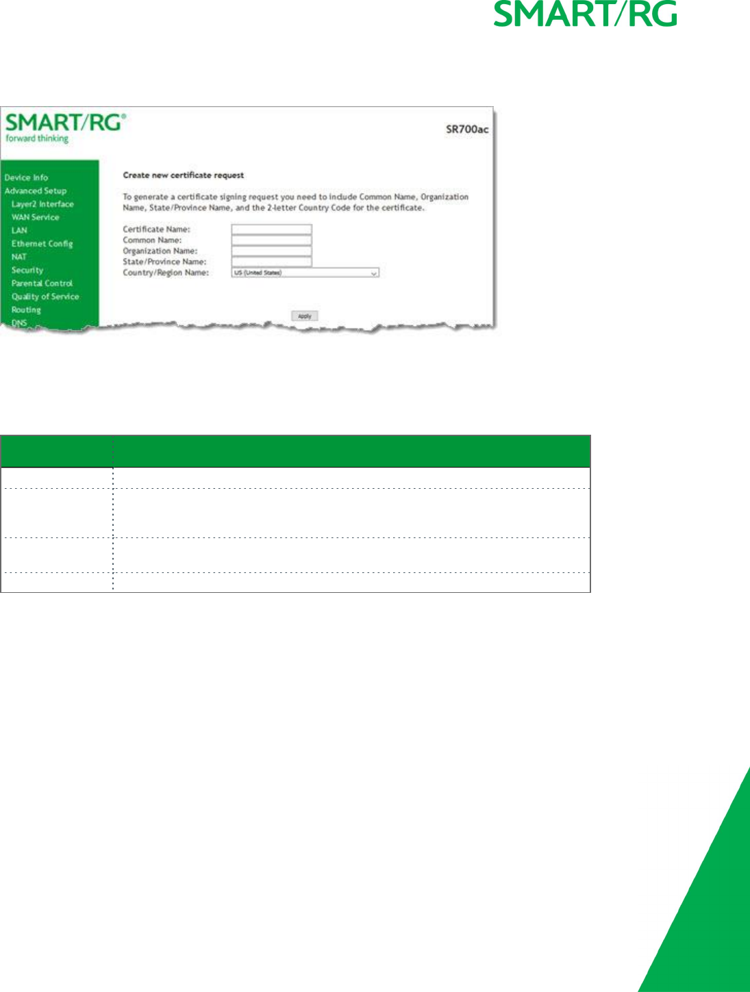
SMARTRG INC. PROPRIETARY AND CONFIDENTIAL. ALL RIGHTS RESERVED. COPYRIGHT © 2017 85
1. In the left navigation bar, click Advanced Setup >Certificate >Local and then click Create Certificate Request. The fol-
lowing page appears.
2. Enter your connection details by completing the appropriate fields. For more information about certificates, refer to the ITU
X.509 standard.
3. Click Apply to complete the request.
The fields on this page are explained in the following table.
Field Name Description
Certificate Name A free-form text field used to describe the intended use of the certificate.
Common Name Enter the IP address (in dotted decimal notation), domain name or email address in
the field provided. The domain name or email address is for identification purposes
and is a free-form text field.
Organization Name Enter the organization for which this certificate is requested. Typically, this is the
name of the company creating the request.
Country/Region Select the country or region in which this certificate will be employed.
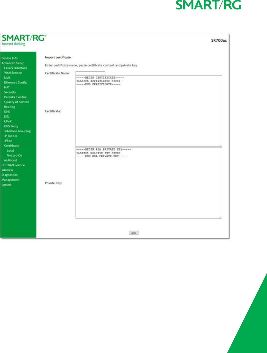
SMARTRG INC. PROPRIETARY AND CONFIDENTIAL. ALL RIGHTS RESERVED. COPYRIGHT © 2017 86
4. To import a certificate and the corresponding private key, click Import Certificate. The following page appears.
5. In the Certificate Name field, type "cpecert".
6. Paste the Certificate details between the BEGIN and END markers.
7. Paste the Private Key information between the BEGIN and END markers.
8. Click Apply to implement this certificate.
Trusted CA
On this page, you import and store up to four trusted certificates. Trusted Certificates are used to identity other gateways to your
gateway as a trusted source.

SMARTRG INC. PROPRIETARY AND CONFIDENTIAL. ALL RIGHTS RESERVED. COPYRIGHT © 2017 87
1. In the left navigation bar, click Advanced Setup > Certificate > Trusted CA and then click Import Certificate. The following
page appears.
2. In the Certificate Name field, type "acscert", and then paste the certificate details between the BEGIN and END markers.
3. Click Apply to commit this certificate.
After you add one certificate, a Remove button appears on the Trusted CA landing page. Click this button to remove the current
certificate and replace it with a new one.

SMARTRG INC. PROPRIETARY AND CONFIDENTIAL. ALL RIGHTS RESERVED. COPYRIGHT © 2017 88
Multicast
Multicast methodology is used for applications shipping information simultaneously to multiple destinations. The most common scen-
ario is Internet television and other streaming media. In IP Multicast, the implementation occurs at the IP routing level, where
routers create the most efficient distribution paths for packets sent to a destination.
On this page, you can configure the multicast settings.
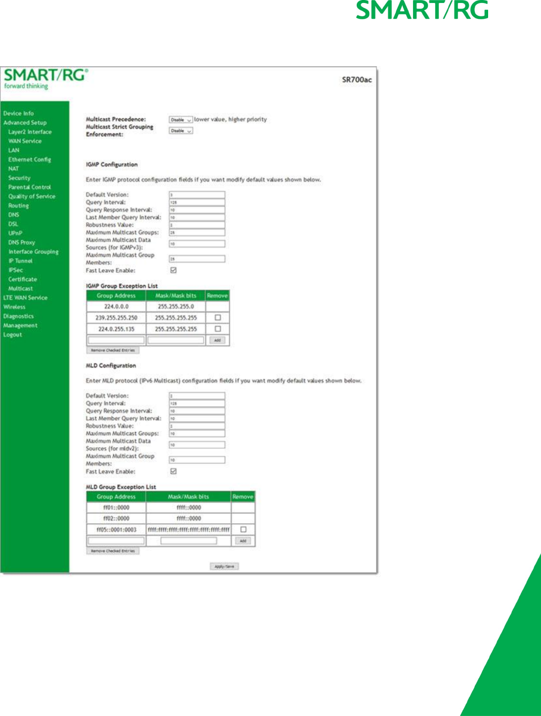
SMARTRG INC. PROPRIETARY AND CONFIDENTIAL. ALL RIGHTS RESERVED. COPYRIGHT © 2017 89
1. In the left navigation bar, select Advanced Setup >Multicast. The following page appears.

SMARTRG INC. PROPRIETARY AND CONFIDENTIAL. ALL RIGHTS RESERVED. COPYRIGHT © 2017 90
2. In the Multicast Precedence field, select whether IGMP packets are given priority handling and at what level. Options are:
lDisable: IGMP packets are not prioritized. This is the default.
lEnable: IGMP packets are prioritized using the multicast precedence value. The lower the multicast precedence
value, the higher that IGMP packets will be placed in the queue.
3. In the Multicast Strict Grouping Enforcement field, select whether grouping is stricly enforced. Options are Disable and
Enable. The default is Disable.
4. Modify the other fields as needed, using the information in the table below. The same fields are provided for both IGMP and
MLD configuration.
5. To add an IPaddress to a group exception list, type the IP address and mask/mask bits in the appropriate fields and click Add.
6. Click Apply/Save to commit your changes.
7. To remove an IP addresses from a group exception list, click the Remove checkbox next to the address and then click
Remove Checked Entries.
The fields on this page are explained in the following table.
Field Name Description
Default Version Enter the supported IGMP version. Options are: 1-3.
Query Interval The interval at which the multicast router sends a query messages to hosts,
expressed in seconds.
If you enter a number below 128, the value is used directly. If you enter a number
128, it is interpreted as an exponent and mantissa.
Query Response Inter-
val
Upon receiving a query packet, a host begins counting down seconds, from a ran-
dom number. When the timer expires, the host sends its report.
Enter the maximum number of seconds that a host can pick to count down from.
The value must be greater than the Query Interval. If using IGMP v1, this value is
fixed at 10 seconds.
Last Member Query
Interval
Enter the maximum response time within which the host must respond to the Out
of Sequence query from the router. The default is 1000ms.
IGMP uses this value when the router receives an IGMPv2 Leave report indicating
at least one host wants to leave the group. Upon receiving the Leave report, the
router verifies whether the interface is configured for IGMP Immediate Leave. If
not, the router sends the out-of-sequence query.
Robustness Value Enter the value representing the complexity of the query. The greater the value,
the more robust the query. Options are: 2-7.
Maximum Multicast
Groups
Enter the maximum number of groups allowed.
Maximum Multicast
Data Sources
Enter the maximum number of data sources allowed. Options are: 1-24.
Maximum Multicast
Group Members
Enter the maximum number of multicast groups that can be joined on a port or
group of ports.
Fast Leave Enable Select whether the IGMP proxy removes group members immediately without
sending a query. Options are:
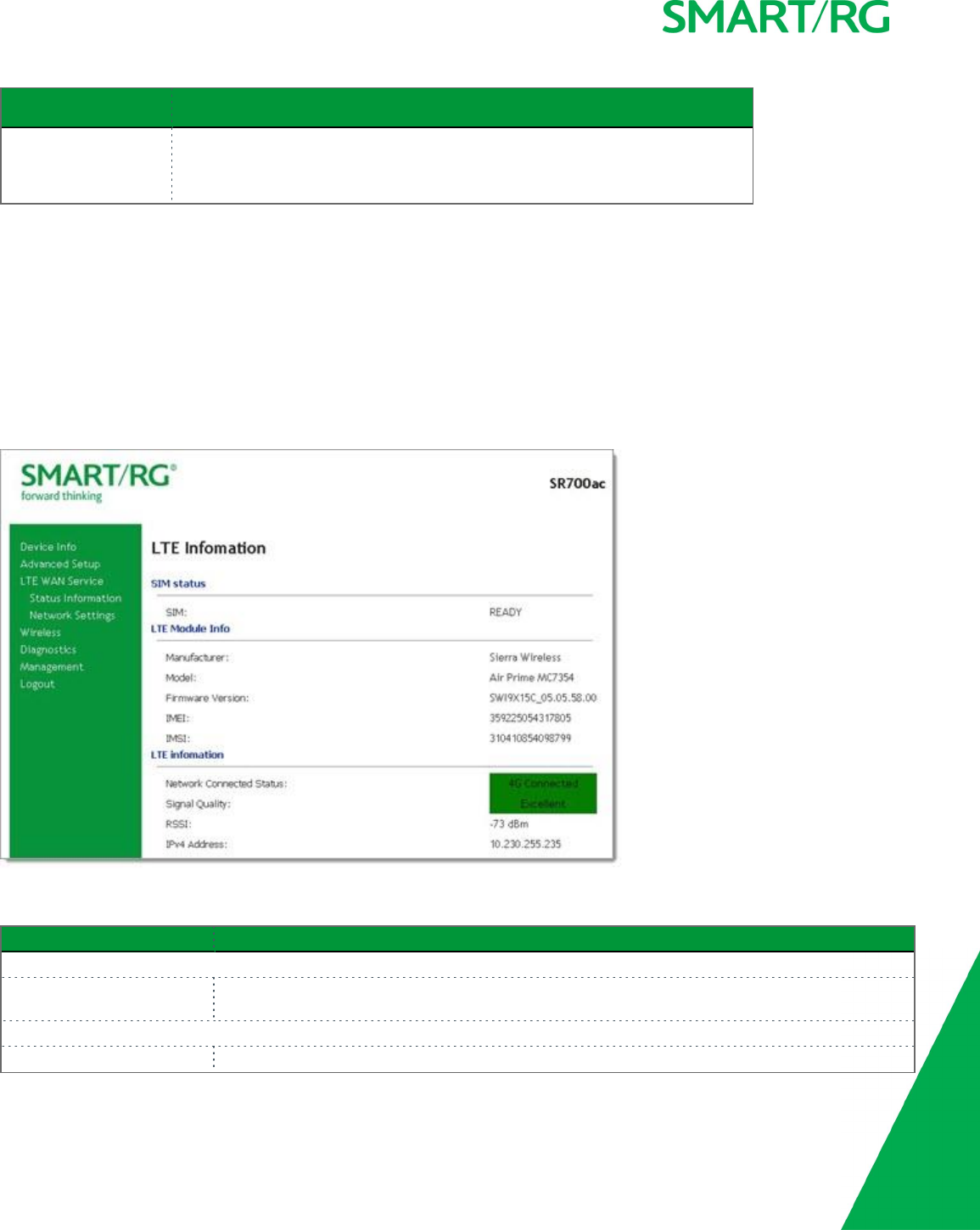
SMARTRG INC. PROPRIETARY AND CONFIDENTIAL. ALL RIGHTS RESERVED. COPYRIGHT © 2017 91
Field Name Description
lEnabled: Group members are removed immediately.
lDisabled: Group members are removed after a query is sent and a
response received.
LTE WAN Service
In this section, you can view LTE WAN status and configure the related network settings.
Status Information
On this page, you can view information about the LTE connection between your provider and your gateway.
In the left menu, click LTE WAN Service >Status Information. The following page appears.
The fields on this page are explained in the following table.
Field Name Description
SIM status section
SIM State of the SIM card if inserted into the SIM slot on the rear of the SR700ac. Options are READY and
NA.
LTE Module Info section
Manufacturer Manufacturer of the LTE Module.
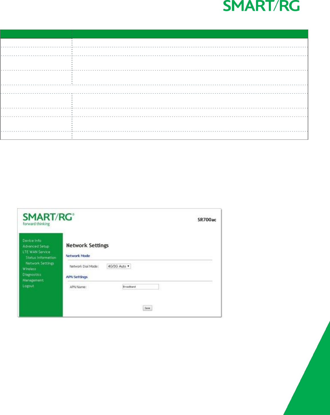
SMARTRG INC. PROPRIETARY AND CONFIDENTIAL. ALL RIGHTS RESERVED. COPYRIGHT © 2017 92
Field Name Description
Model Model of the LTE Module.
Firmware Version Firmware version of the LTE Module
IMEI International Mobile Equipment Identity is a unique 15-digit number used to identify valid equip-
ment on a network provider.
IMSI International Mobile Subscriber Identity is a unique number stored on the SIM Card used to identify
the subscriber of the network provider.
LTE Information section
Network Connected Status State of the LTE connection. Options are 4G Connected,3G Connected,Disconnected,Not
Attached, and SIM Card not detected.
Signal Quality Quality of the LTE signal. Options are Excellent,Average,Poor, and No Signal.
RSSI Received Signal Strength Indicator. The measured dBm level of the received radio signal with the
network provider. If no signal is found, “No Signal” appears in this field.
IPv4 Address IPv4 Address for the LTE connection.
Network Settings
On this page, you can configure the Network Settings of the LTE connection between your provider and your gateway.
1. Insert the SIM card received from your network provider into the SIM card slot on the back of the SR700ac with the gold con-
tacts facing up.
Note: The SIM card slot is located beneath the black WAN Ethernet port on the back of the gateway.
2. In the left navigation bar, click LTE WAN Service >Network Settings. The following page appears.
3. Modify the settings as needed, using the information provided in the table below.
4. Click Save to commit your changes.
Note: The settings take up to 90 seconds to save.
The fields on this page are explained in the following table.

SMARTRG INC. PROPRIETARY AND CONFIDENTIAL. ALL RIGHTS RESERVED. COPYRIGHT © 2017 93
Field
Name
Description
Network Mode section
Network
Dial
Mode
Select the Network Dial Mode. Options are 4G/3G Auto, 4G Only, and 3G Only.
APN Settings section
APN
Name
Enter the Access Point Name for your network provider.
Wireless
In this section, you can configure the wireless interface settings for your gateway, including basic and advanced settings, MAC fil-
tering, and wireless bridging.
Note: While separate pages are provided for both wireless bands (2.4 Ghz and 5 Ghz), the fields are the same for both bands.
Basic
On this page, you can configure basic features of the Wi-Fi LAN interface. You can enable or disable the Wi-Fi LAN interface, hide the
network from active scans, set the Wi-Fi network name (also known as SSID) and restrict the channel set based on country require-
ments.
1. In the left navigation bar, click Wireless. The following page appears.
Note: Menu options appear for both wireless channels. Click the wireless channel that you want to configure and proceed
with configuration. The same fields are available for both channels.
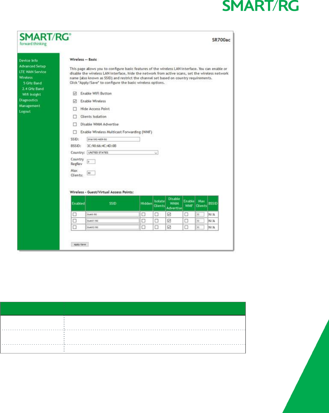
SMARTRG INC. PROPRIETARY AND CONFIDENTIAL. ALL RIGHTS RESERVED. COPYRIGHT © 2017 94
2. Modify the settings as desired, using the information provided in the table below. The table at the bottom of the page lists
the guest/virtual access points defined for your gateway. If desired, you can define up to three virtual access points for guest
use.
3. Click Apply/Save to commit your settings.
The fields on this page are explained in the following table.
Field Name Description
Enable WiFi Button This option is enabled by default. To disable the gateway's Wi-Fi button, click
the checkbox to clear it.
Enable Wireless This option is enabled by default. To disable the gateway's Wi-Fi radio, click
the checkbox to clear it.
Hide Access Point Click to hide the access point SSID from end users.

SMARTRG INC. PROPRIETARY AND CONFIDENTIAL. ALL RIGHTS RESERVED. COPYRIGHT © 2017 95
Field Name Description
Clients Isolation Click to prevent LAN client devices from communicating with one another on
the wireless network.
Disable WMM Advertise Click to stop the wireless from advertising Wireless Multimedia (WMM) func-
tionality. WMM provides basic Quality of Service (QOS) for applications.
Enable Wireless Multicast
Forwarding
Click to enable Wireless Multicast Forwarding (WMF). Multicast traffic is for-
warded across wireless clients.
SSID Enter the Wi-Fi SSID.
BSSID Enter the Basic Service Set Identifier (BSSID) to provide the MAC address
assigned to the wireless router.
Country Select the country in which the gateway is deployed.
Country RegRev Enter the revision number of the regulations being followed for the selected
country. The default is 0.
Max Clients Enter the maximum number of clients that can access the route wirelessly.
Wireless - Guest/Virtual Access Points table
Enabled Click to enable a virtual wireless access point for guest access.
SSID Enter your wireless SSID.
Hidden Click to hide the SSID from being broadcast publicly.
Isolate Clients Click to prevent client PCs from communicating with one another.
Disable WMM Advertise Click to stop the wireless from advertising Wireless Multimedia (WMM) func-
tionality.
Enable WMF Click to enable Wireless Multicast Forwarding (WMF).
Max Clients Enter the maximum number of clients allowed for this wireless channel.
BSSID Displays the Basic Service Set Identifier or N/A.
Security
On this page, you can configure security features of the wireless LAN interface, either manually or via Wi-Fi Protected Setup (WPS).
Note: When WPS is enabled, the STA PIN and Authorized MAC fields appear. If both of these fields are empty, PBC becomes the
default value. If Hide Access Point is enabled or the MAC filter list is empty with "Allow" selected, WPS2 will be disabled.
1. In the left navigation bar, click Wireless >Security. The Security page appears for the 5 GHz band page. To configure the 2.4
GH band, click 2.4 Ghz Band in the left menu.
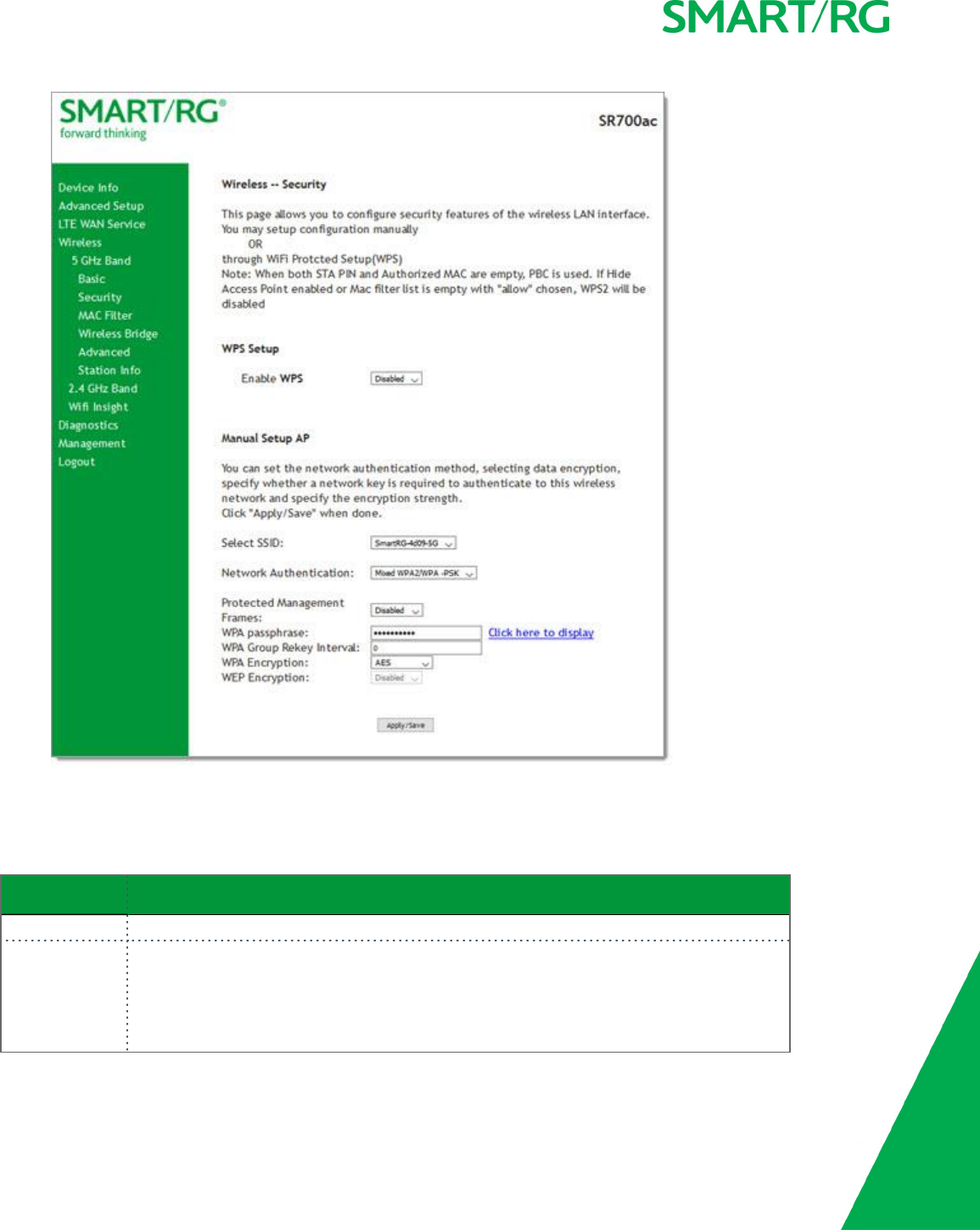
SMARTRG INC. PROPRIETARY AND CONFIDENTIAL. ALL RIGHTS RESERVED. COPYRIGHT © 2017 96
2. Modify the settings as needed, using the information provided in the field description table.
3. Click Apply/Save to commit your changes.
The fields on this page are explained in the following table.
Field Name Description
Enable WPS Select to enable Wi-Fi Protected Setup. Options are: Enabled and Disabled.
Add Client (Appears when WPS is enabled) Select the method for generating the WPS PIN. Options are:
Enter STA PIN and Use AP PIN.
To add an enrollee station, click Add Enrollee.
Note: If the PIN and Set Authorized Station MAC fields are left blank, the PBC (push-button)

SMARTRG INC. PROPRIETARY AND CONFIDENTIAL. ALL RIGHTS RESERVED. COPYRIGHT © 2017 97
Field Name Description
mode is automatically made active.
Set WPS AP Mode (Appears when WPS is enabled) Select how security is assigned to clients.
lConfigured: The gateway assigns security settings to clients.
lUnconfigured: An external client assigns security settings to the gateway.
Device PIN (Appears when WPS is enabled) The PIN for the gateway. This value is generated by the access
point.
Manual Setup AP section
Select SSID Select the SSID of the wireless network to which this security configuration will apply.
Network
Authentication
Select the desired network security authentication type. Options are: Open,Shared,802.1X,
WPA2,WPA2-PSK,Mixed WPA2/WPA, and Mixed WPA2/WPA-PSK.
The fields shown in the Manual Setup AP section of the page vary based on the network authentication method that you select. The
variations are explained in the following sections:
l"Open & Shared Authentication"
l"802.1X Authentication"
l"WPA2 & Mixed WPA2/WPA Authentication"
l"WPA2-PSK & Mixed WPA2/WPA-PSK Authentication"
Open & Shared Authentication
The same configuration fields apply for both Open and Shared authentication types. However, WPS may not be used with the Shared
method.
1. On the Wireless > Security page for the band that you want to configure, select Open or Shared in the Network Authentic-
ation field.
2. For Open authentication, in the Enable WPS field, select Enabled. The following fields appear.
Note: For Shared authentication, this option is set to Disabled and cannot be changed.
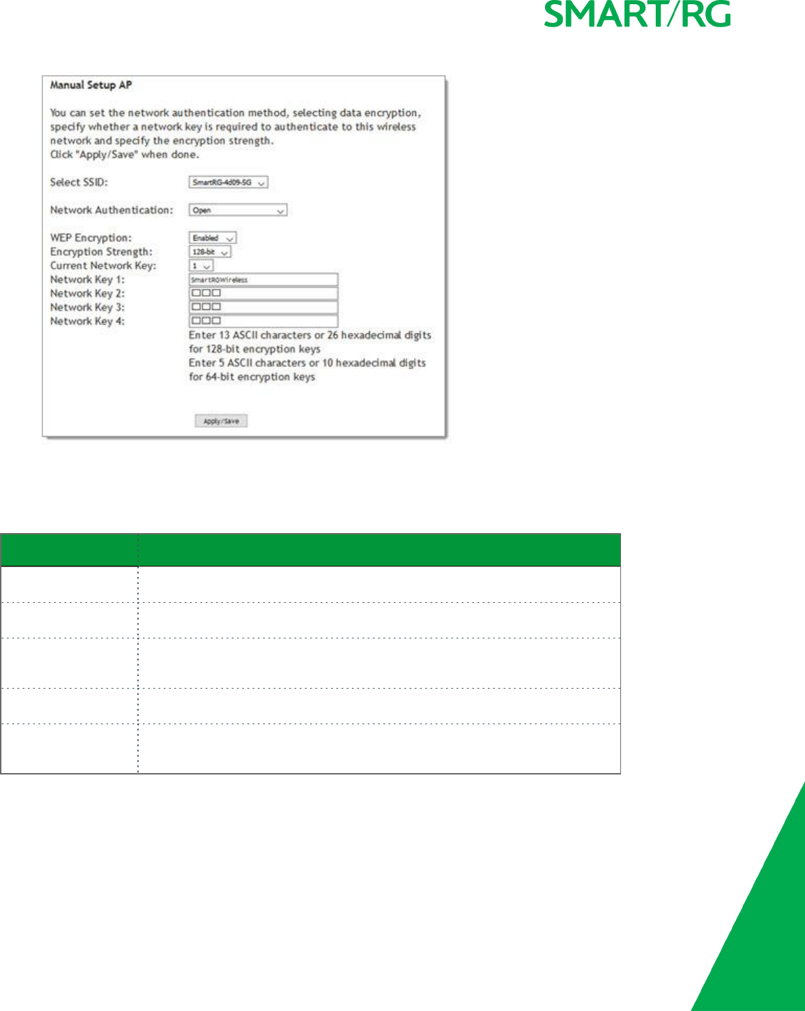
SMARTRG INC. PROPRIETARY AND CONFIDENTIAL. ALL RIGHTS RESERVED. COPYRIGHT © 2017 98
3. Fill in the fields, using the information in the field description table below.
4. Click Apply/Save to save the settings.
The fields on this page are explained in the following table.
Field Name Description
Select SSID Select the SSID of the wireless network to which this security configuration will
apply.
WEP Encryption Select to enable Wired Equivalent Privacy (WEP) mode. Options are Enabled and
Disabled.
Encryption Strength (Appears when WEP Encryption is set to Enabled) Select the length of the encryp-
tion method. Options are 128-bit and 64-bit. 128-bit is the more robust option for
security.
Current Network Key (Appears when WEP Encryption is set to Enabled) Select which of the four keys is
presently in effect.
Network Key 1-4 (Appears when WEP Encryption is set to Enabled) Enter up to four encryption
keys using the on-screen instructions to achieve the desired security strength (128-
bit or 64-bit).
802.1X Authentication
1. On the Wireless > Security page for the band that you want to configure, select 802.1X in the Network Authentication field.
The following fields appear.
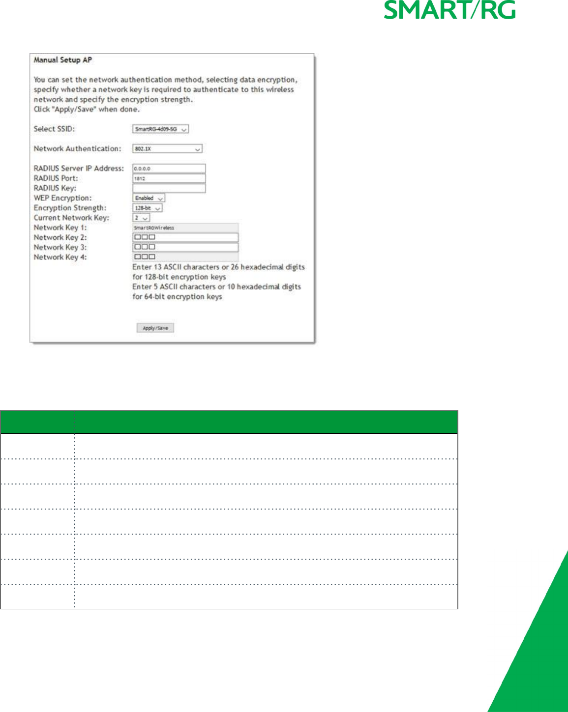
SMARTRG INC. PROPRIETARY AND CONFIDENTIAL. ALL RIGHTS RESERVED. COPYRIGHT © 2017 99
2. Fill in the fields, using the information in the field description table below.
3. Click Apply/Save to save the settings.
The fields on this page are explained in the following table.
Field Name Description
RADIUS Server IP
address
Enter the IP address of the RADIUS (Remote Authentication Dial In User Service) server asso-
ciated with your network.
RADIUS Port Enter the port number for the RADIUS server. Port 1812 is the current standard for RADIUS
authentication per the IETF RFC 2865. Older servers may use port 1645. Options are 1-65535.
RADIUS Key (Optional) Enter the encryption key (if required) needed to authenticate to the specified
RADIUS Server.
WEP Encryption Wired Equivalent Privacy (WEP) encryption mode is enabled by default and cannot be
changed.
Encryption
Strength
Select the length of the encryption method. Options are 128-bit and 64-bit. 128-bit is the
more robust option for security.
Current Network
Key
Select which of the four keys is presently in effect.
Network Key 1-4 Enterone or two encryption keys using the on-screen instructions to achieve the desired secur-
ity strength (128-bit or 64-bit).
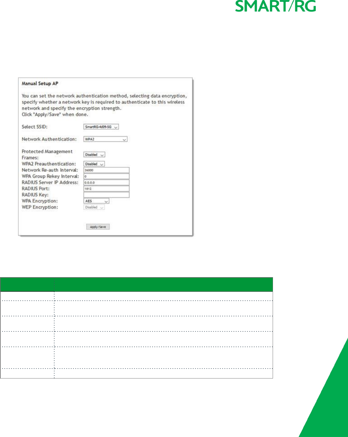
SMARTRG INC. PROPRIETARY AND CONFIDENTIAL. ALL RIGHTS RESERVED. COPYRIGHT © 2017 100
WPA2 & Mixed WPA2/WPA Authentication
The same configuration fields apply for both WPA2 and Mixed WPA2/WPA authentication methods.
1. On the Wireless > Security page for the band that you want to configure, select WPA2 or Mixed WPA2/WPA in the Network
Authentication field. The following fields appear.
2. Fill in the fields, using the information in the field description table below.
3. Click Apply/Save to save the settings.
The fields on this page are explained in the following table.
Field Name Description
Select SSID Select the SSID of the wireless network to which this security configuration will apply.
Protected Man-
agement Frames
Select whether to enable this option. Options are Disabled, Capable, and Required.
The default is Disabled.
WPA2 Preau-
thentication
Select whether clients can pre-authenticate with the gateway while still connected to
another AP. Options are Enabled and Disabled. The default is Disabled.
Network Re-Auth
Interval
Enter the interval at which the client must re-authenticate with the gateway. Options
are ??? seconds. The default is 36000 seconds (10 hours).
WPA Group Rekey
Interval
The frequency at which the gateway automatically updates the group key and sends it
to connected LAN client devices. Options are 1-65535 seconds. The default is 0(dis-
abled).
RADIUS Server IP Enter the IP address of the RADIUS (Remote Authentication Dial In User Service) server
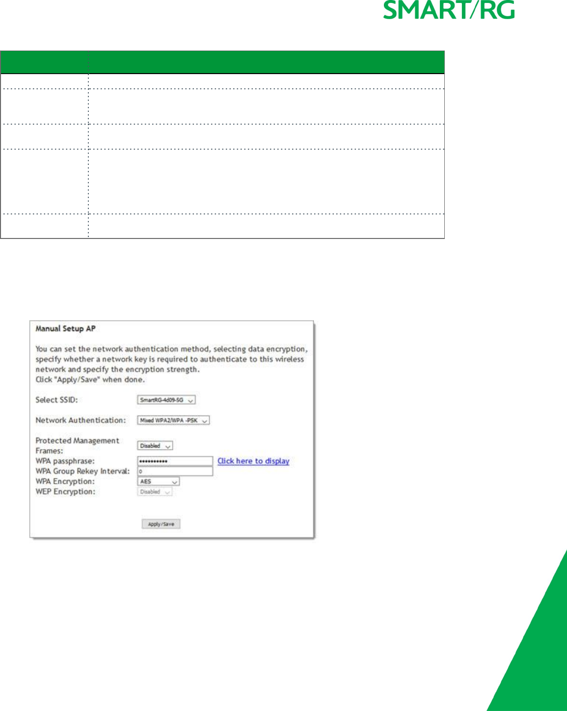
SMARTRG INC. PROPRIETARY AND CONFIDENTIAL. ALL RIGHTS RESERVED. COPYRIGHT © 2017 101
Field Name Description
address associated with your network.
RADIUS Port Enter the port number for the RADIUS server. Port 1812 is the current standard for
RADIUS authentication per the IETF RFC 2865. Older servers may use port 1645. Options
are 1-65535.
RADIUS Key (Optional) Enter the encryption key (if required) needed to authenticate to the spe-
cified RADIUS Server.
WPA Encryption Select the encryption standard. This field displays the option most compatible with the
selected network authentication method. Options are:
lAES: Advanced Encryption Standard.
lTKIP+AES: AES combined with TKIP (Temporary Key Integrity Protocol).
WEP Encryption Wired Equivalent Privacy (WEP) encryption mode is disabled by default and cannot be
changed.
WPA2-PSK & Mixed WPA2/WPA-PSK Authentication
The same configuration fields apply for both WPA2-PSK and Mixed WPA2/WPA-PSK authentication methods.
1. On the Wireless > Security page for the band that you want to configure, select WPA2-PSK or Mixed WPA2/WPA-PSK in the
Network Authentication field. The fields shown below appear.
2. Fill in the fields, using the information in the field description table below.
3. Click Apply/Save to save the settings.
The fields on this page are explained in the following table.
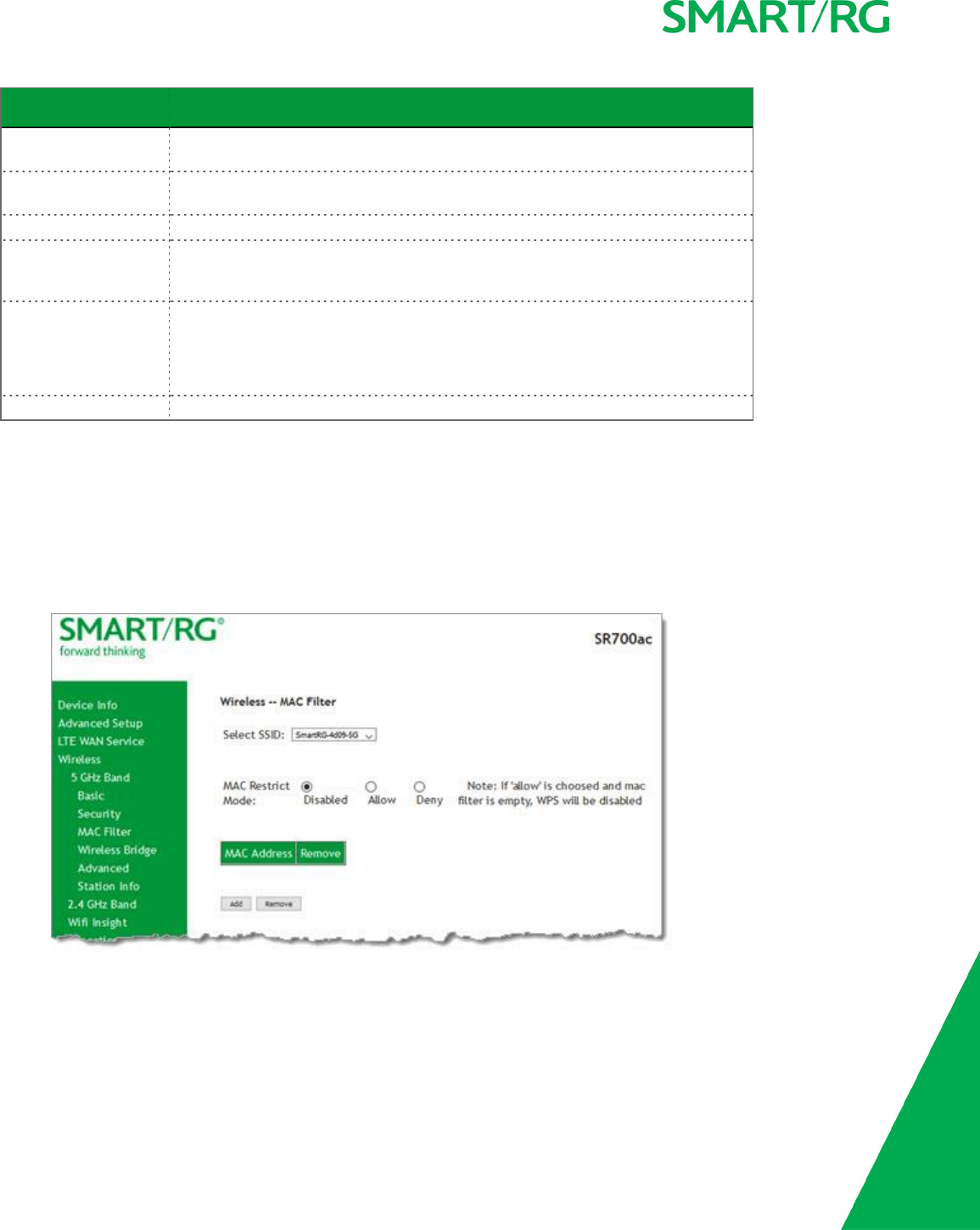
SMARTRG INC. PROPRIETARY AND CONFIDENTIAL. ALL RIGHTS RESERVED. COPYRIGHT © 2017 102
Field Name Description
Select SSID Select the SSID of the wireless network to which this security configuration will
apply.
Protected Man-
agement Frames
Select whether to enable this option. Options are Disabled, Capable, and
Required. The default is Disabled.
WPA passphrase Enter the security password to be used by this security configuration.
WPA Group Rekey Inter-
val
The frequency at which the gateway automatically updates the group key and
sends it to connected LAN client devices. Options are: 1-65535 seconds. The
default is 0(disabled).
WPA Encryption Select the encryption standard. This field displays the option most compatible
with the selected network authentication method. Options are:
lAES: Advanced Encryption Standard.
lTKIP+AES: AES combined with TKIP (Temporary Key Integrity Protocol).
WEP Encryption Wired Equivalent Privacy (WEP) mode is set to Disabled and cannot be changed.
MAC Filter
MAC Filtering refers to an access control methodology whereby the 48-bit address assigned to each LAN host NIC is used to determ-
ine access to the network. It is also known as Layer 2 address filtering.
On this page, you can configure the filter settings.
1. In the left navigation bar, click Wireless >MAC Filter. The following page appears.
2. Select the SSID to which this MAC filter rule should apply.
3. In the MAC Restrict Mode field, select whether to apply MAC filtering. Options are:
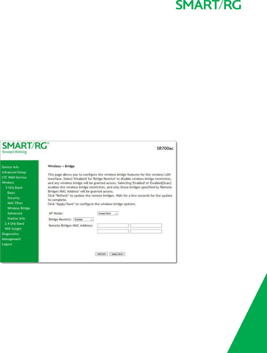
SMARTRG INC. PROPRIETARY AND CONFIDENTIAL. ALL RIGHTS RESERVED. COPYRIGHT © 2017 103
lDisabled: MAC filtering is off.
lAllow: Access for the specified MAC address is permitted. You must add at least one MAC address.
lDeny: Access for the specified MAC address is rejected.
4. To add a MAC address to the filter list:
a. Click Add.
b. Enter the MAC address.
c. Click Apply/Save.
You are returned to the main MAC filtering page.
5. To remove a MAC address from the list, click the Remove checkbox next to it and then click the Remove button below the
list.
6. Click Apply/Save to commit your changes.
Wireless Bridge
On this page, you can configure the wireless bridge features of the wireless LAN interface. Wireless Bridge is also known as Wireless
Distribution System.
1. In the left navigation bar, click Wireless >Wireless Bridge. The following page appears.
2. Modify the settings as needed, using the information in the following table.
3. Click Apply/Save to commit your changes.
The fields on this page are explained in the following table.

SMARTRG INC. PROPRIETARY AND CONFIDENTIAL. ALL RIGHTS RESERVED. COPYRIGHT © 2017 104
Field Name Description
AP Mode Select whether to enable or disable access point (AP) functionality. Options are:
lWireless Bridge: Disables AP functionality.
lAccess Point: Enables AP functionality. Wireless bridge functionality is still available
and wireless stations can associate to the AP.
Bridge Restrict (Optional) Select to enable or disable wireless bridge restriction. Options are:
lEnabled or Enabled(Scan): Enables wireless bridge restriction. This is the default.
Only bridges specified in the Remote Bridge MAC Address field are granted access.
Click Refresh to update the station list. The list takes a few seconds to update.
lDisabled: Disables wireless bridge restriction. Any wireless bridge is granted access.
Remote Bridges
MAC Address
Enter up to four MAC addresses of remote bridges to be allowed access.
Advanced
On this page, you can configure the advanced features of the wireless LAN interface. You can select a particular channel on which to
operate, force the transmission rate to a desired speed, set the fragmentation threshold, the RTS threshold, the wakeup interval
for clients in power-save mode, and more.
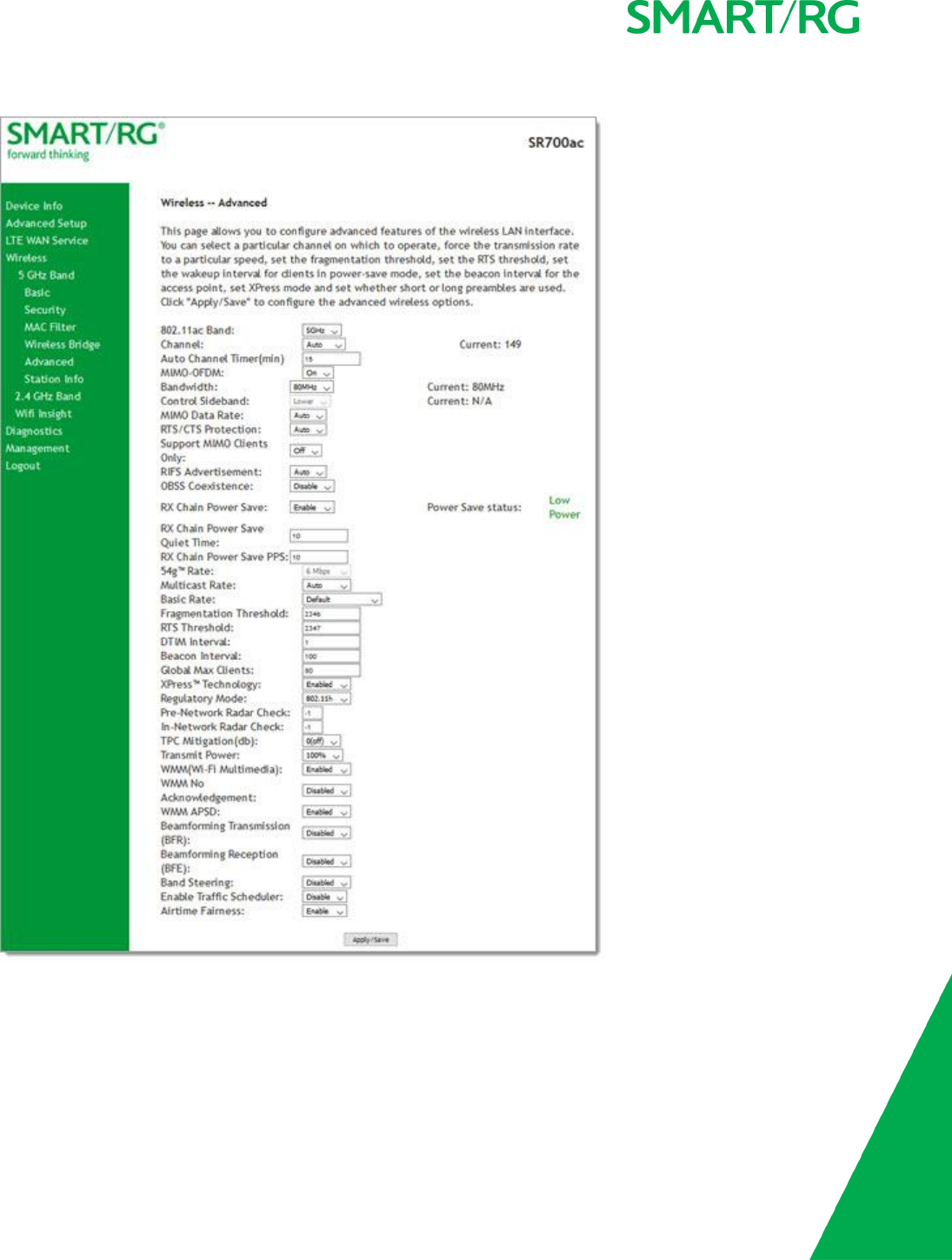
SMARTRG INC. PROPRIETARY AND CONFIDENTIAL. ALL RIGHTS RESERVED. COPYRIGHT © 2017 105
1. In the left navigation bar, click Wireless >Advanced. The following page appears.
2. Modify the fields as needed, using the information in the field description table.
3. Click Apply/Save to commit your changes.
The fields on this page are explained in the following table.

SMARTRG INC. PROPRIETARY AND CONFIDENTIAL. ALL RIGHTS RESERVED. COPYRIGHT © 2017 106
Field Name Description
Band The wireless band that you are configuring. This field is set to 5GHz in the Wireless >
5 GHz Band submenu and to 2.4GHz in the Wireless >2.4 GHz Band submenu.
Channel Select the Wi-Fi channel you want to use. Options include Auto and 36/80 -161/80
for the 5 GHz band and are Auto and 1-7for the 2.4 GHz band. It is recommended to
use only non-overlapping channels, e.g., 1,5and 7.
Auto Channel Timer
(min)
Enter the frequency (in minutes) at which the gateway scans channels for inter-
ference. If a threshold of inference is detected, a new channel will be selected auto-
matically. Options are: 0-65535 minutes. The default is 15 minutes.
MIMO-OFDM This option is set to On and cannot be changed.
Bandwidth Select the operating bandwidth. Options are:
l20MHz: Only one 20MHz band is utilized.
l40MHz: Better throughput is provided by using two adjacent 20MHz bands.
l80MHZ: Best throughput.
Control Sideband (Applies only to 40 MHz operation) The control sideband is the 20 MHz channel on
which the network is advertised, where client devices will find beacons. Options are:
lLower: The additional 20 MHz of bandwidth for data will be positioned above
the control channel.
lUpper: The additional 20 MHz of bandwidth for data will be positioned below
the control channel. Also, selecting this option changes the channel choices
displayed.
MIMO Data Rate The desired physical transmission rate. This option is set to Auto (the Auto-Fallback
feature is enabled) and cannot be changed. This allows the gateway to automatically
use the fastest possible data rate. Auto-Fallback will negotiate the best possible con-
nection speed between the gateway and a wireless client.
RTS/CTS Protection Select whether to enable 802.11n and legacy clients to both work effectively on the
network. Options are:
lAuto: Provides maximum security but produces a noticeable impact on
throughput. With this option, RTS/CTS behavior permits legacy clients to
become aware of 802.11n transmit times, but decreases overall throughput.
This is the default.
lOff: Provides better throughput.
Support MIMO Clients
Only
(Available for SR515ac models only) Select whether to restrict non-MIMO clients from
accessing the gateway. Options are On and Off. The default is Off.
RIFS Advertisement Reduced Inter-Frame Space (RIFS). Improves performance by reducing dead time
required between OFDM transmissions. Options are Auto and Off.
Recommended primarily for "greenfield" deployments that include only 802.11n cli-
ents, and no legacy clients.
OBSS Coexistence Coexistence of Overlapping Basic Service Sets (OBSS) prevents overlapping in the 20
MHz and 40 MHz frequencies. Options are:
lDisable: The gateway advertises and operates in 40 MHz mode regardless of
what other networks are configured nearby.

SMARTRG INC. PROPRIETARY AND CONFIDENTIAL. ALL RIGHTS RESERVED. COPYRIGHT © 2017 107
Field Name Description
lEnable: The gateway automatically reverts to 20 MHz channel bandwidth
when another WiFi network within 2 channels of its own channel is detected or
when a client device with its 40 MHz Intolerant bit set is detected.
RX Power Chain Save Select whether to turn on power-save mode. Options are Disable and Enable. The
default is Enable.
Note: Before setting this parameter, set 802.11n/EWC to Auto.
RX Power Chain Save
Quiet Time
Enter the delay time (in seconds) between when system activity ceases and power-
save mode engages. Options are: 0-2147483647 seconds. The default is 10 seconds.
RX Power Chain Save
PPS
Enter a throughput threshold (in seconds) for when the router engages power-save
mode after the quiet time seconds have elapsed. Options are: 0-2147483647 pack-
ets per second. The default is 10 seconds.
54g™ rate This options is set to 6 Mbps and cannot be changed.
Multicast rate Select the desired packet transmit rate for multicast. Options are Auto and 6-54
Mbps.
Basic Rate Select the basic rate. Options are Default,All,6 & 12 Mbps, and 6 &12 & 24 Mbps.
Fragmentation
Threshold
Enter the size at which packets will be fragmented into smaller units. The primary
consideration for this setting is the size/capability of the circuit. Options are 256 -
2346 bytes. The default is 2346 bytes.
Note: A high packet error rate is an indication that a slightly increased fragmentation
threshold is needed. When possible, the default value of 2346 bytes should be main-
tained. Poor throughput is a likely result of setting this threshold too low.
RTS Threshold Enter the RTS (Request to Send) packet size beyond which the WLAN client hardware
invokes its RTS/CTS mechanism. Smaller packets will otherwise be sent not using
RTS/CTS. Options are 256 -2347 bytes. The default is 2347 (disabled).
DTIM Interval Enter the Delivery Traffic Indication Message (DTIM or Beacon rate) countdown vari-
able used to indicate when the next window is available to client devices for listening
to buffered broadcast and multicast messages. Options are 1and 65535. The default
is 1.
Beacon Interval Enter the time interval (in milliseconds) between beacon transmissions. Beacon trans-
missions make known the presence of an access point and convey to wireless NICs
when to awake from power save mode to check for buffered frames at the access
point. Options are 1and 65535 ms. The default is 100 ms.
Global Max Clients Enter the maximum number of client devices that can connect to the router. Options
are 1-255. The default is 80.
Xpress™ Technology Select whether to enable Xpress Technology. This technology is compliant with draft
specifications of two planned wireless industry standards. Options are Enabled and
Disabled. The default is Enabled.
Regulatory Mode Select whether to enable support for 802.11 regulations. Options are Disabled,
802.11h, and 802.11d. The default is 802.11h.
Pre-Network Radar
Check
The radar check parameter setting for traffic trying to access your gateway from out-
side the network. The displayed value is -1.
In-Network Radar The radar check setting for traffic trying to access your gateway from inside your net-

SMARTRG INC. PROPRIETARY AND CONFIDENTIAL. ALL RIGHTS RESERVED. COPYRIGHT © 2017 108
Field Name Description
Check work. The displayed value is -1.
TPC Mitigation(db) Select the TPC mitigation value in db. Options are 0(off),2,3, and 4. The default is 0
(off).
Transmit Power Select the desired output power (by percentage). Options are 20%,40%,60%,80%,
and 100%. The default is 100%.
WMM (Wi-Fi Mul-
timedia)
Select whether to enable this technology. It allows multimedia services (audio, video
and voice packets) to get higher priority for transmission. Options are Auto,Enabled,
and Disabled. the default is Enabled.
WMM No Acknow-
ledgement
Select whether acknowledgements are sent (applied at the MAC level). Enabling this
option allows better throughput but, in a noisy RF environment, higher error rates
may result. Options are Enabled and Disabled. The default is Disabled.
WMM APSD Select whether to enable Automatic Power Save Delivery, a power consumption sav-
ing feature. Options are Enabled and Disabled. T The default is Disabled.
Beamforming Trans-
mission (BFR)
Select to concentrate the transmission signal at the gateway location. This results in a
better signal and potentially better throughput. Options are Enabled and Disabled.
The default is Disabled.
Beamforming Recep-
tion (BFE)
Select to concentrate the transmission signal at the gateway location. Options are
Enabled and Disabled. The default is Disabled.
Band Steering Select whether to detect if the client has the ability to use two bands. When
enabled, the less-congested 5GHz network is selected (by blocking the client's
2.4GHz network). Options are Disabled and Enabled. The default is Disabled.
Enable Traffic Sched-
uler
(Available for SR515ac models only) Select whether to enable scheduling of traffic to
improve efficienty and increase usable bandwidth for some types of packets by delay-
ing other types. Options are Disable and Enable. The default is Disable.
Airtime Fairness Select how the gateway will manage the receiving signal with other devices. Options
are Disable and Enable. The default is Enable.
Station Info
On this page, you can view authenticated wireless stations and their status.
In the left navigation bar, select Wireless >Station Info. The following page appears.
Click Refresh to update the information.

SMARTRG INC. PROPRIETARY AND CONFIDENTIAL. ALL RIGHTS RESERVED. COPYRIGHT © 2017 109
Wifi Insight
On this page, you can configure the WiFi Insight system.
1. In the left navigation menu, click Wireless >Wifi Insight. The following page appears. You can also reach this page by click-
ing Wireless >Wifi Insight >Configure.
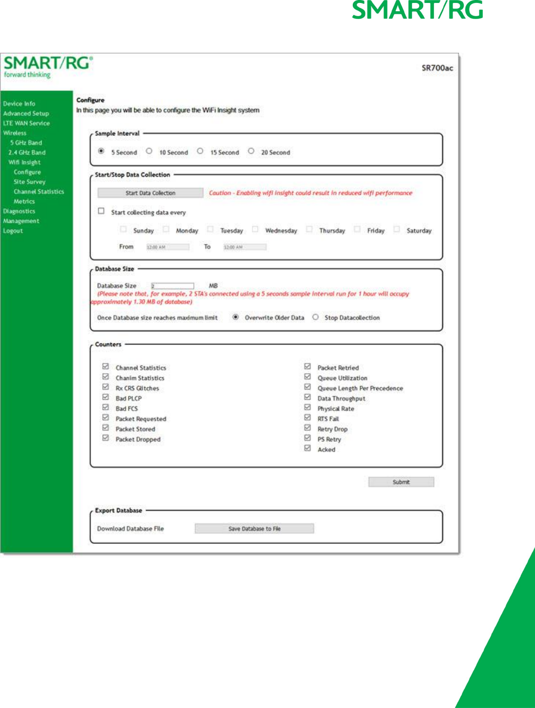
SMARTRG INC. PROPRIETARY AND CONFIDENTIAL. ALL RIGHTS RESERVED. COPYRIGHT © 2017 110
2. In the Sample Interval section, select the number of seconds for sampling to occur. Options are 5,10,15, and 20 seconds.
The default is 5seconds.

SMARTRG INC. PROPRIETARY AND CONFIDENTIAL. ALL RIGHTS RESERVED. COPYRIGHT © 2017 111
3. In the Start/Stop Data Collection section, configure the data sample:
a. Click Start collecting data every. The days-of-the-week checkboxes become active.
b. Select the days of the week when the data should be collected.
c. In the From and To fields, click in the fields and use the plus (+) and minus (-) icons to change the start and end
times for collection. You can close the selection box by clicking the Xon the box or clicking in the field again.
4. In the Database Size section:
a. In the Database Size field, enter the maximum size for the database file where the collected data will be stored.
The default is 2MB.
b. (Optional) Select whether to stop data collection when the maximum size is reached. Options are Overwrite Older
Data and Stop Datacollection. The default is Overwrite Older Data.
5. (Optional) In the Counters list, clear any counter options that you do not need. The default is to collect all counters.
6. Click Submit to save the configuration. The Start Data Collection button label changes to Stop Data Collection.
7. To stop data collection, click the Stop Data Collection button in the Start/Stop Data Collection section.
8. To export a database, click Save Database to File. The open/save dialog box appears. Click OK to save or click Open and OK
to view.
Site Survey
On this page, you can view signal strength and other details for your wireless networks.
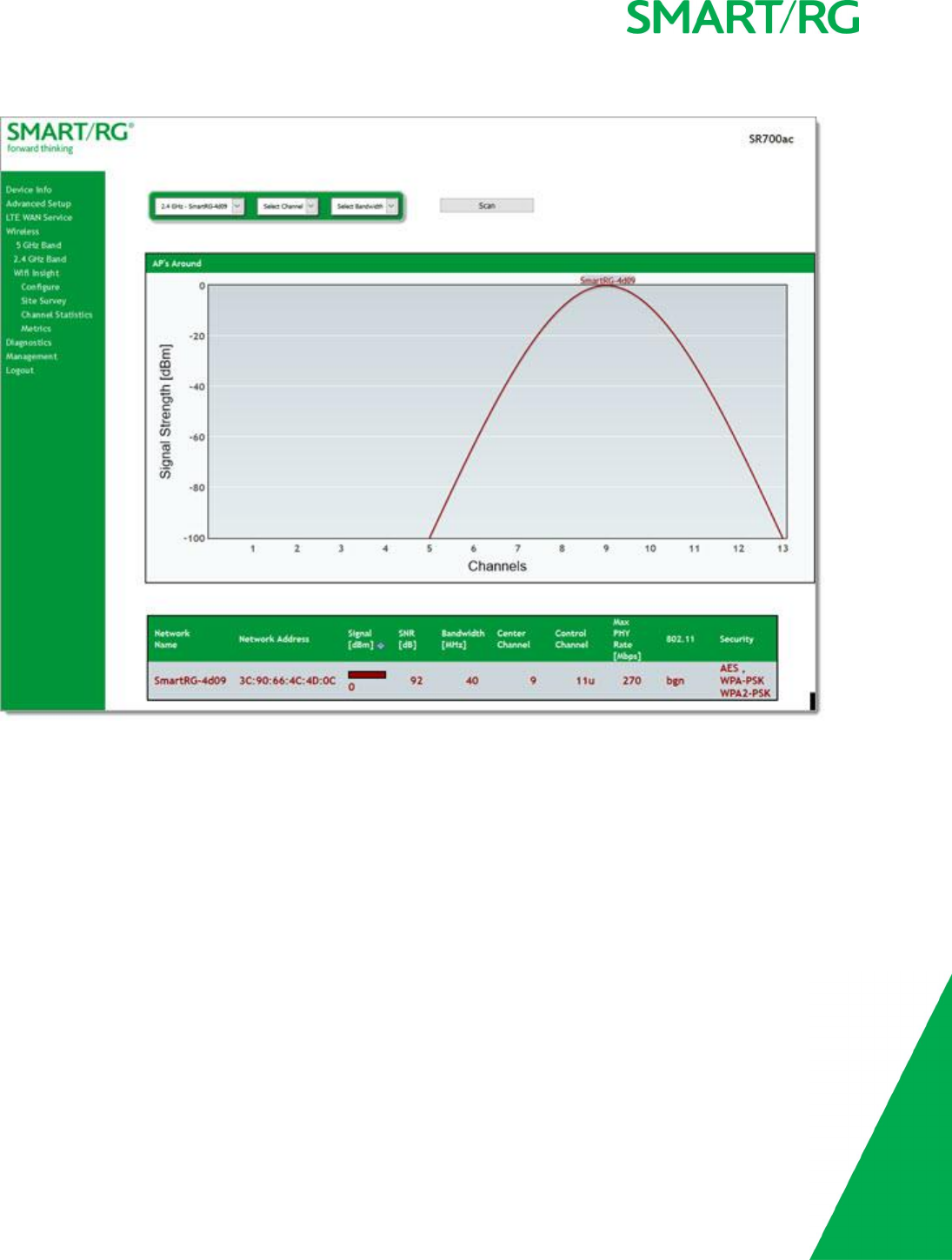
SMARTRG INC. PROPRIETARY AND CONFIDENTIAL. ALL RIGHTS RESERVED. COPYRIGHT © 2017 112
1. In the left navigation menu, click Wireless >Wifi Insight >Site Survey. The following page appears.
2. In the first field above the chart, select the wireless network that you want to review.
3. In the Select Channel field, select the channel that you want to review.
4. In the Select Bandwidth field, select the bandwidth.
5. Click Scan. The page refreshes to show the requested information.
Channel Statistics
On this page, you can view signal strength, channel capacity, interference, and other details for for specific channels.
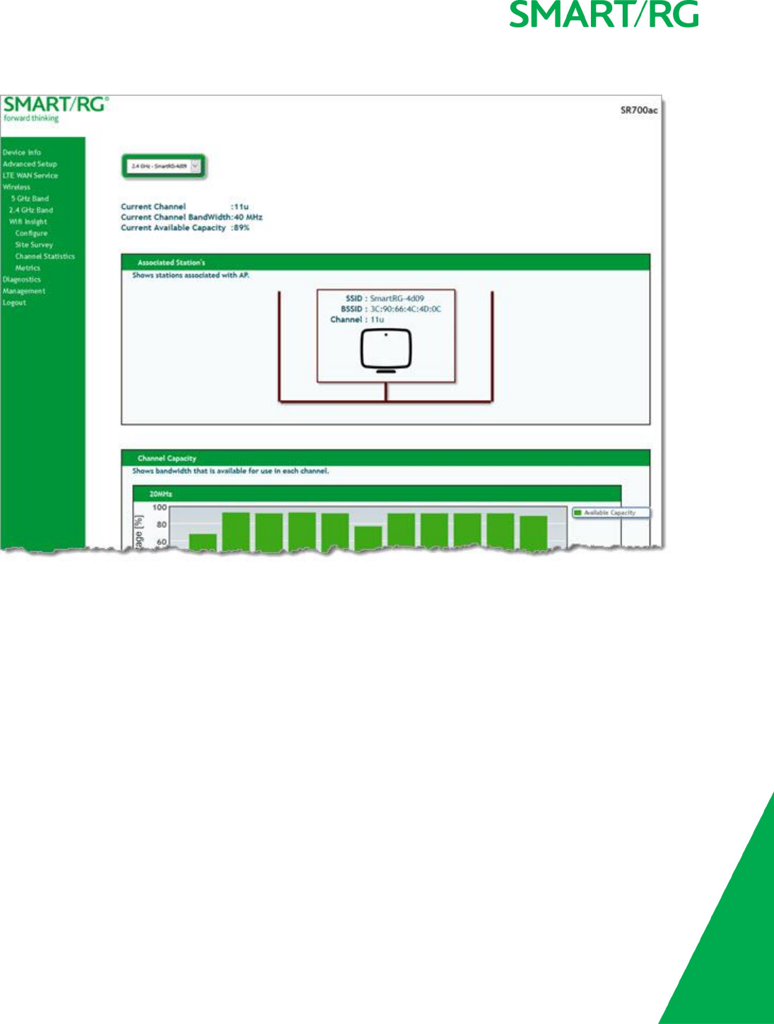
SMARTRG INC. PROPRIETARY AND CONFIDENTIAL. ALL RIGHTS RESERVED. COPYRIGHT © 2017 113
1. In the left navigation menu, click Wireless >Wifi Insight >Channel Statistics. The following page appears.
2. In the field at the top of the page, select the wireless band to review. Information is shown for associated stations, channel
capacity, interference levels, adjacent channels, and channel distribution.
Metrics
On this page, you can view glitch counter, chanim, associated stations, and packet queue statistics for your wireless networks.
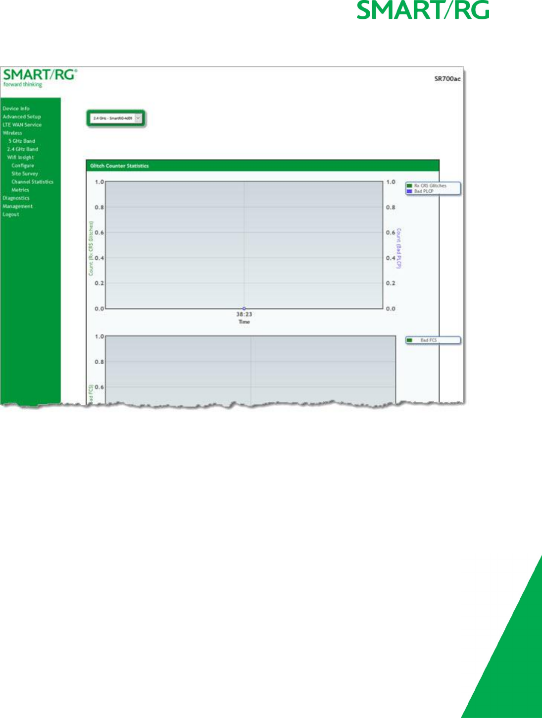
SMARTRG INC. PROPRIETARY AND CONFIDENTIAL. ALL RIGHTS RESERVED. COPYRIGHT © 2017 114
1. In the left navigation menu, click Wireless >Wifi Insight >Metrics. The following page appears.
2. In the field at the top of the page, select the wireless band to review. Information is shown for glitch counters, chanim, asso-
ciated stations, and packet queues.
Diagnostics
in this section, you can run line performance tests. Three legs of the data path are included in the available tests: LAN connectivity,
DSL connectivity and Internet connectivity tests.
You can also ping a host or trace a connection.
Diagnostics
On this page, you can view information about your DSL connection.
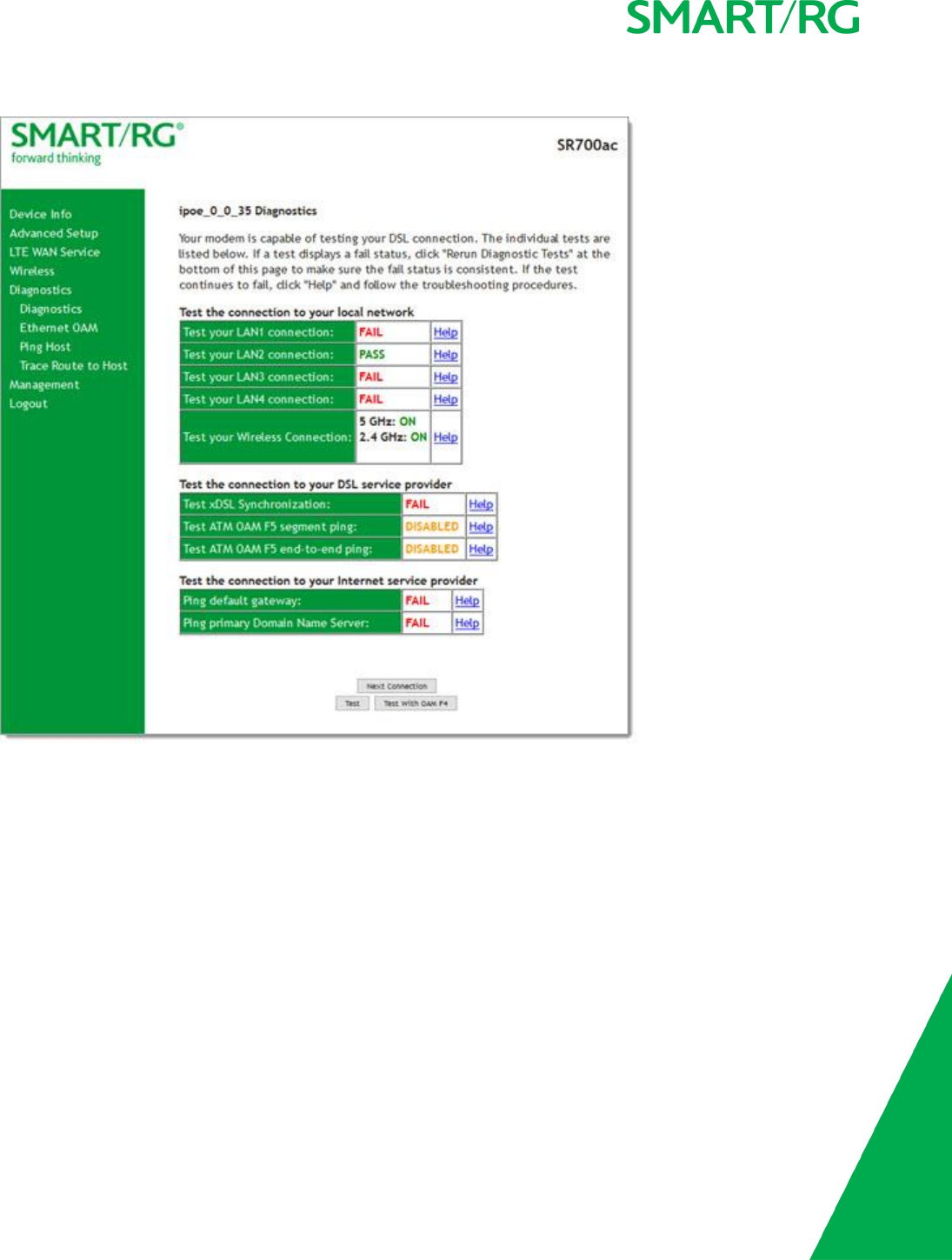
SMARTRG INC. PROPRIETARY AND CONFIDENTIAL. ALL RIGHTS RESERVED. COPYRIGHT © 2017 115
1. In the left navigation bar, click Diagnostics >Diagnostics. The following page appears.
2. To refresh the data, click Test at the bottom of the page. The normal test method is initiated, utilizing OAM F5 loopback
cells. The table is updated with fresh diagnostic information about connection integrity.
To learn more about what is being tested and what actions to take when a test fails, click the Help link at the far right of
each line item.
3. To test at the VP level in lieu of at an individual VC connection, click Test With OAM F4. Status is shown for both wireless
bands in the Test your Wireless Connection row.
4. To view information about other connections, click the Next Connection and Previous Connection buttons to navigate
through them.
Ethernet OAM
On this page, you can view diagnostics regarding your VDSL PTM or Ethernet WAN connection. Fault Management is compliant with
IEEE 802.1ag for Connectivity Fault Management.

SMARTRG INC. PROPRIETARY AND CONFIDENTIAL. ALL RIGHTS RESERVED. COPYRIGHT © 2017 116
1. In the left navigation bar, click Diagnostics >Ethernet OAM. The following page appears.
2. Modify the fields as needed, using the information in the table below.
3. Click Apply/Save to commit your changes.
The fields on this page are explained in the following table.
Field Name Description
Ethernet Link OAM (802.3ah) section
Ethernet Link OAM
(802.3ah)
Click the Enabled checkbox to set options for this protocol. The fields described
below appear. Only the WAN Interface and Active Mode fields are required.
WAN Interface Select the WAN interface that you want tested.
OAM ID Enter the ID of this OAM configuration. Only positive numbers are allowed.
Auto Event Select whether to create event log entries automatically.
Variable Retrieval Select to enable on-demand link diagnostics, including bit-error-rate approximation.
Link Events Select to enable reporting of critical conditions that may cause link failure.
Remote Loopback Select to enable on-demand link diagnostics, including bit-error-rate approximation.
Active Mode Click to enable this feature.
Ethernet Service OAM (802.1ag/Y.1731) section
Ethernet Service OAM
(802.1ag/Y.1731)
Click the Enabled checkbox and then click 802.1ag or Y.1731 to set options for this
protocol. The fields described below appear. Only the WAN Interface and Active
Mode fields are required.
WAN Interface Select the WAN interface that you want tested.
MD Level (Appears for the 802.1ag option only) Select the domain level for this maintenance
domain. Options are 0-7. The larger the domain, the higher the value you should
select.
MD Name (Appears for the 802.1ag option only) Enter the name of the maintenance domain,
e.g., Broadcom.
MA ID (Appears for the 802.1ag option only) Enter the MA ID, e.g., BRCM.
MEG Level (Appears for the Y.1731 option only) Enter the MEG level for this service.
MEG ID (Appears for the Y.1731 option only) Enter the MEG ID for this service.

SMARTRG INC. PROPRIETARY AND CONFIDENTIAL. ALL RIGHTS RESERVED. COPYRIGHT © 2017 117
Field Name Description
Local MEP ID Enter the ID of the local MEP. Options are 1-8191.
Local MEP VLAN ID Enter the ID of the VLAN for the local MEP. Options are 1-4094. The default is -1
(no VLAN tag).
CCM Transmission Select to enable CCM transmission.
Remote MEP ID Enter the ID of the remote MEP. Options are 1-8191. The default is -1 (no remote
MEP).
Loopback and Linktrace Test section
Target MAC Enter the MAC address for the test, e.g., 02:10:18:aa:bb:cc.
Linktrace TTL Enter the maximum number of hops allowed. Options are 1-233. The default is -1
(no hop limit).
Loopback Result Shows the results of the loopback test.
Linktrace Result Shows the results of the linktrace test.
Ping Host
On this page, you can ping a server by host name or IP address.
1. In the left navigation menu, click Diagnostics Tools >Ping. The following page appears.
2. Enter the host name or IP address.
3. Click Ping Host. The details of the ping appear on the page.

SMARTRG INC. PROPRIETARY AND CONFIDENTIAL. ALL RIGHTS RESERVED. COPYRIGHT © 2017 118
Trace Route to Host
On this page, you can use the Trace Route utility to trace a connection.
1. In the left navigation menu, click Diagnostics Tools >Trace Route to Host. The following page appears.
2. Enter the host name or IP address that you want to trace.
3. Click Trace Route to Host). The details of the trace appear on the page.
Management
In this section, you can manage configuration files, access control, management server configurations, SNMP Agent settings, and
work with event logs.
Settings
In this section, you can back up the current settings, restore saved settings, or reset the gateway to default settings.
Backup
You can back up the current settings for your gateway to a file stored on your computer.

SMARTRG INC. PROPRIETARY AND CONFIDENTIAL. ALL RIGHTS RESERVED. COPYRIGHT © 2017 119
1. In the left navigation bar, click Management >Settings. The following page appears.
2. To save a backup file of the currently running settings to a local drive, click Backup Running Settings. The open/save dialog
box appears. Click OK. The backupsettings.conf file is created in your default download location.
3. To save a backup file of the default settings to a local drive, click Backup Default Settings. The open/save dialog box
appears. Click OK. The backupdefaultsettings.conf file is created in your default download location.
Note: If you plan to create backups frequently, you may want to rename the backup files by appending dates to the filename. Other-
wise, every new backup file overwrites the existing backup file.

SMARTRG INC. PROPRIETARY AND CONFIDENTIAL. ALL RIGHTS RESERVED. COPYRIGHT © 2017 120
Update
On this page, you can restore previously backed-up gateway settings. Both Current and Default settings can be managed here.
1. In the left navigation bar, click Management >Settings >Update. The following page appears.
2. Click the Browse button for the type of setting you wish to restore.
3. Locate the desired configuration file on your local system and click Open.
4. Click the appropriate Update button.
The gateway reboots when the update has completed.

SMARTRG INC. PROPRIETARY AND CONFIDENTIAL. ALL RIGHTS RESERVED. COPYRIGHT © 2017 121
Restore Default
On this page, you can reset the gateway to its default settings which can be the factory defaults or defaults that you customized and
stored. For details, see the "Restore Default" and "Restore Default" sections .
1. In the left navigation bar, click Management >Settings >Restore Default. The following page appears.
2. Click Restore Default Settings. The gateway is rebooted.
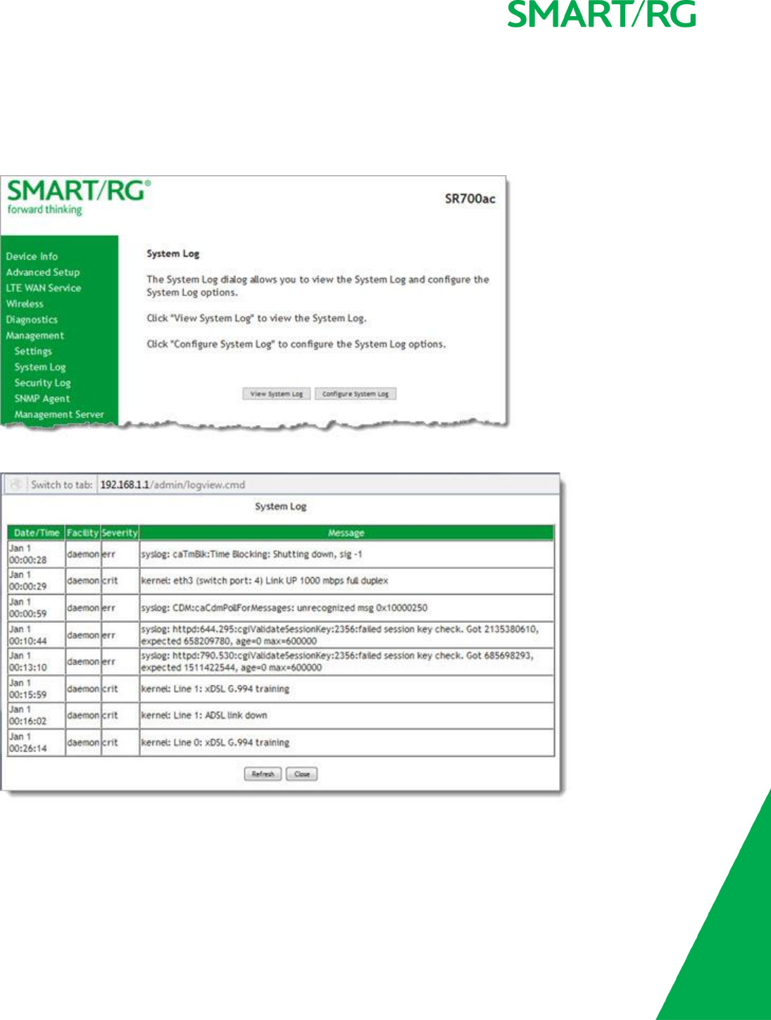
SMARTRG INC. PROPRIETARY AND CONFIDENTIAL. ALL RIGHTS RESERVED. COPYRIGHT © 2017 122
System Log
On this page, you can view and configure the system log generated for your gateway.
1. In the left navigation bar, click Management >System Log. The following page appears.
2. To view the contents of the system log, click View System Log. The System Log details page appears.
3. To update the displayed entries, click Refresh.
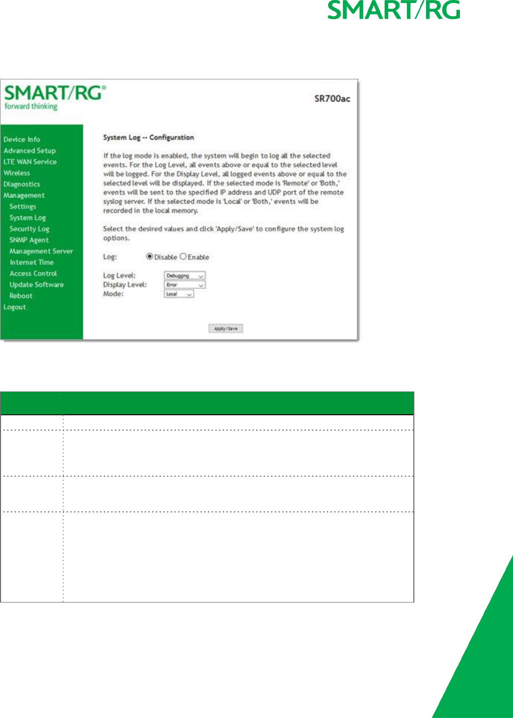
SMARTRG INC. PROPRIETARY AND CONFIDENTIAL. ALL RIGHTS RESERVED. COPYRIGHT © 2017 123
4. To modify the system log settings:
a. Click Configure System Log. The System Log - Configuration page appears.
b. Modify the settings as needed.
The following table describes the options for configuration of the system log.
Action Description
Log Select to turn logging off or on. The default is Disable.
Logging Level Select Error unless actively troubleshooting a situation with a subscriber for which
increased log detail is required. Options are Emergency,Alert,Critical,Error, Warn-
ing,Notice,Informational, and Debugging. The options are listed in top-down order
of increasing detail. The default is Debugging (all information).
Display Level Select Error unless actively troubleshooting a situation with a subscriber for which
increased detail is required. This field has the same options as the Logging Level
field. The default is Error.
Mode Controls where log events will be sent. Options are:
lTo send logs to the specified IP address and UDP port of a remote syslog
server, select Remote or Both.
lTo record events in the local memory of your SmartRG gateway, select Local
or Both.
The default is Local.

SMARTRG INC. PROPRIETARY AND CONFIDENTIAL. ALL RIGHTS RESERVED. COPYRIGHT © 2017 124
c. Click Apply/Save to save your changes.
Security Log
The security log contains a history of events related to sensitive access to the gateway. Logged events include:
lPassword change success/failure
lAuthorized login success/failure
lAuthorized user logged out
lSecurity lockout added/removed
lAuthorized/Unauthorized resource access
lSoftware update
1. In the left navigation bar, click Management >Security Log. The following page appears.
2. Do any of the following:
lTo view the log, click View.
lTo purge the log entries and start fresh, click Reset. A confirmation message appears. Click Close.
lTo export the log to a local drive, click the here link in the last line of the instructions on the page. The log appears in
the browser window. You can save the page or select all of the log text, paste into a Notepad window and save the
file.
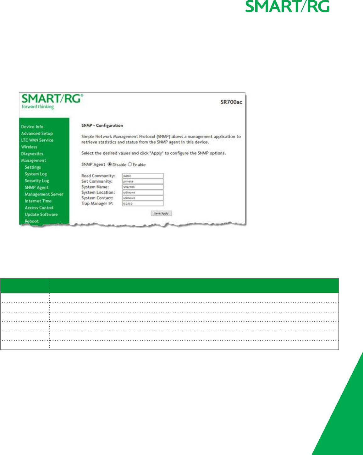
SMARTRG INC. PROPRIETARY AND CONFIDENTIAL. ALL RIGHTS RESERVED. COPYRIGHT © 2017 125
SNMP Agent
On this page, you can configure the SNMP (Simple Network Management Protocol) settings to retrieve statistics from the SNMP agent
for the gateway. You can enable or disable the SNMP agent and set parameters such as the read community, system name and trap
manager IP.
1. In the left navigation bar, click Management >SNMP Agent. The following page appears.
2. To enable SNMP, click Enable in the SNMP Agent field.
3. Modify the other fields as needed, using the information in the following table.
4. Click Save/Apply to commit your changes.
The fields on this page are explained in the following table.
Field Name Description
Read Community The options are public and private. The default is public.
Set Community The options are public and private. The default is private.
System Name The name of the system.
System Location (Optional) The location of the system.
System Contact (Optional) The contact for the system.
Trap Manager IP (Optional) The IP address where the trap manager is installed.

SMARTRG INC. PROPRIETARY AND CONFIDENTIAL. ALL RIGHTS RESERVED. COPYRIGHT © 2017 126
Management Server
A management server is an Auto Configuration Server (ACS) such as Cisco Prime Home which offers significant advantages in terms of
automation and productivity when managing subscriber devices in the field.
In this section, you can configure ACS settings for the TR-069 client and configure STUN server settings.
TR-069 Client
On this page, you can configure the gateway with details about the management ACS to which this gateway will be linked.
SmartRG gateways support TR-069-based standards for remote management. The TR-069 client page is preset with default con-
nection parameters and generally only needs to be enabled, pointed to the ACS URL, and any required ACS credentials entered.
SmartRG products can accommodate several ACS products, including:
lDevice Manager by SmartRG
lCisco Prime Home
lClearVision
lCalix Consumer ACS
If you need to modify the request defaults, consult the ACS manufacturer’s documentation.
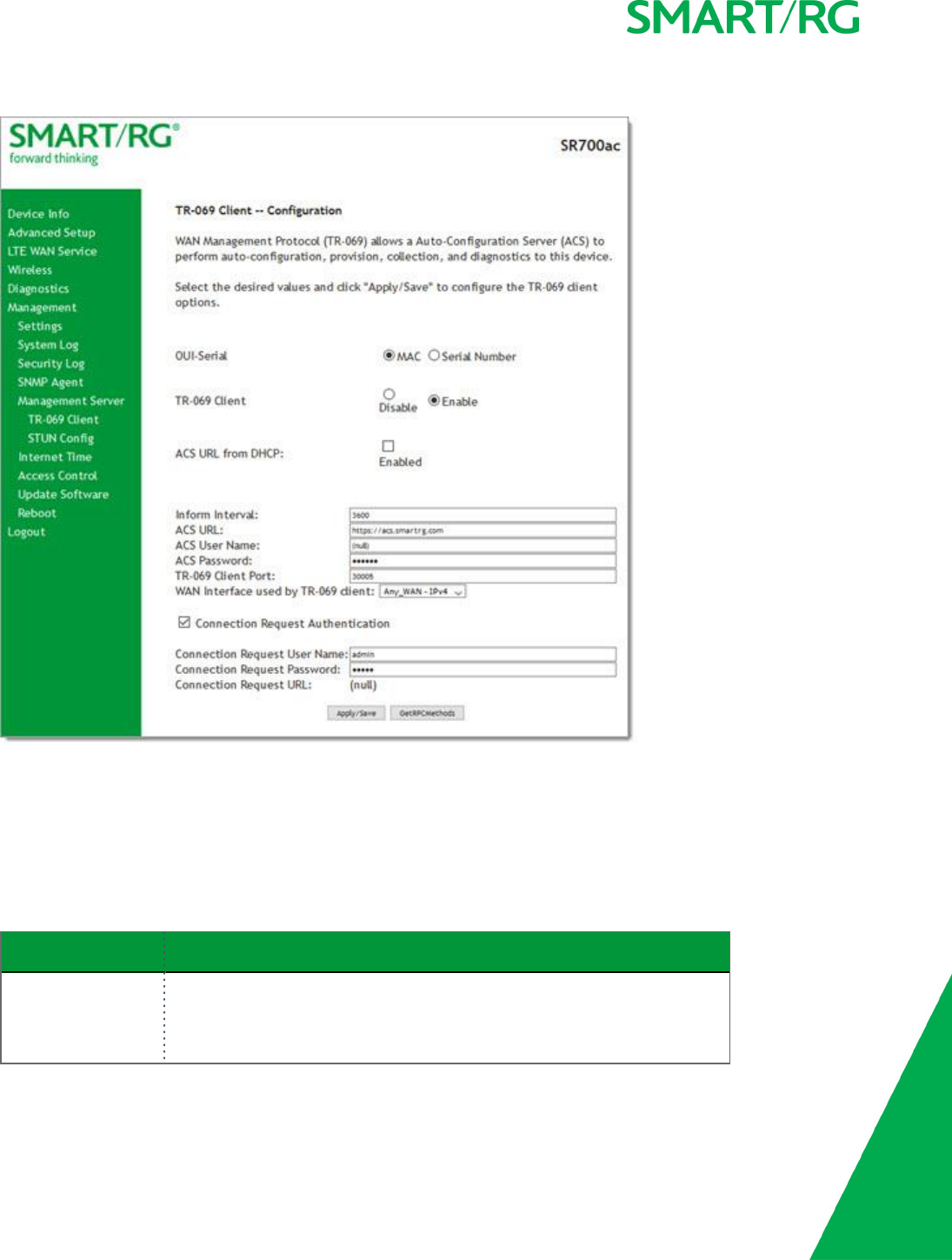
SMARTRG INC. PROPRIETARY AND CONFIDENTIAL. ALL RIGHTS RESERVED. COPYRIGHT © 2017 127
1. In the left navigation bar, click Management >Management Server >TR-069 Management. The following page appears.
2. Update or complete the necessary fields per the instructions from your ACS platform vendor.
3. Click Apply/Save to commit your changes.
Note: This manual does not cover the setup of your ACS. Consult the materials provided by your ACS vendor to determine the
appropriate parameters and server settings for configuring remote WAN side management via an ACS using the TR-069 Pro-
tocol.
The fields on this page are explained in the following table.
Field Name Description
OUI-Serial Select whether to use the base MAC address or the serial number of your gate-
way when connecting to the ACS. This value may display in an ACS user inter-
face when looking at the device details of a particular gateway. Options are:
lMAC: This option is the most typical scenarion and the default. For firm-

SMARTRG INC. PROPRIETARY AND CONFIDENTIAL. ALL RIGHTS RESERVED. COPYRIGHT © 2017 128
Field Name Description
ware versions prior to 2.5.0.2, MAC is the only available option.
lSerial Number: This option is available for SmartRG gateways using firm-
ware versions later than 2.5.0.2.
TR-069 Client Enable or disable the TR-069 client on the CPE. You can disable the TR-069
WAN Management Client if no ACS is employed.
Note: If you may want to add an ACS to your infrastructure in the future, it is
recommended that you leave this option enabled. Once this feature is dis-
abled, every gateway deployed with this setting must be manually/locally re-
configured to re-enable this client.
ACS URL from DHCP Click the Enabled checkbox to enable your gateway to obtain the ACS URL via
DHCP.
Inform Interval The frequency (in seconds) with which the CPE (gateway) checks in with the
ACS to sync and exchange data. A typical production environment entails CPEs
in the field informing to the ACS once/day or every 86,400 seconds. The
default is 3600 seconds (1 hour).
ACS URL Enter the URL for the CPE to connect to the ACS using the CPE WAN Man-
agement Protocol. This parameter MUST be in the form of a valid HTTP or
HTTPS URL. An HTTPS URL indicates that the ACS supports SSL. The "host" por-
tion of this URL is used by the CPE for validating the certificate from the ACS
when using certificate-based authentication.
You can include a port specification suffix if your ACS platform requires it, e.g.,
http://customer.acs.wanmanagmentservices.com:30005 where 30005 is the
port number. The default port is 30005.
ACS User Name Enter the user name by which this gateway logs in to the ACS. The default
username is typically admin.
ACS Password Enter the password to authenticate the above user name. The default pass-
word is typically admin.
TR-069 Client Port Enter the TR-069 port number. The default is 30005.
WAN Interface used
by TR-069 client
Select Any_WAN,LAN,Loopback, or a configured connection to declare how
this gateway will connect to the ACS.
4. (Optional) Configure the modem client Connection Request mechanism used by your ACS for communication with subscriber
gateways. Use the information provided in the following table.
Field Name Description
Connection Request
Authentication
This option is enabled by default. Click the checkbox to disable this option.
The fields listed below are hidden.
Connection Request
Username
Enter the user name by which this gateway authenticates the ACS. Contact
your ACS provider for this information.
Connection Request
Password
Enter the password by which this gateway will authenticate to the ACS.
Contact your ACS provider for this information.

SMARTRG INC. PROPRIETARY AND CONFIDENTIAL. ALL RIGHTS RESERVED. COPYRIGHT © 2017 129
Field Name Description
Connection Request
URL
This option is set to (null) by default and cannot be changed.
5. To force the gateway to attempt to sync with the ACS, click the GetRPCMethods button. This will assist you in verifying the
TR-069 parameters entered above.
STUN Config
STUN stands for “Simple Traversal of UDP through NATs”. STUN enables a device to find out its public IP address and the type of NAT
service it is sitting behind.
STUN is most commonly used with older modems under ACS management connected via a NAT gateway. NAT accommodates a LAN-
side device that has been allocated a Private IP address such as a CPE device on a private network behind an ONT. In this instance,
the regular CWMP Connection Request mechanism to talk to the modem gateway cannot be used to initiate a session with that ACS.
A STUN server receives STUN requests and sends STUN responses. STUN servers are generally attached to the public Internet.
On this page, when a STUN server is present within the infrastructure of the Service Provider, you can configure this gateway with
the connectivity specifics for that server.
1. In the left navigation bar, click Management >Management Server >STUN Config. The following page appears.
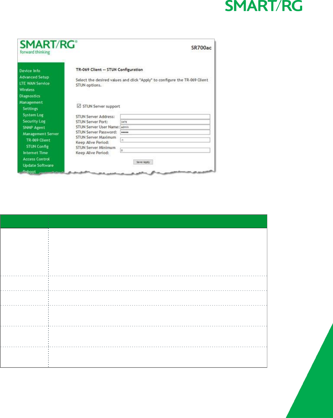
SMARTRG INC. PROPRIETARY AND CONFIDENTIAL. ALL RIGHTS RESERVED. COPYRIGHT © 2017 130
2. To view the required STUN settings, click STUN Server Support. Additional fields appear.
3. Complete each field in accordance with the implementation specifics of your server.
4. Click Save/Apply to commit your changes.
The fields on this page are explained in the following table.
Field Name Description
STUN Server
Address
The physical STUN server’s assigned network address. An invalid address will produce an
immediate on-page error message from the gateway. You can enter a maximum of 256 char-
acters.
An ACS server may also have STUN functionality running on the same physical box. Consult
your ACS vendor for implementation options and also TR-069 protocol documentation, if
necessary.
STUN Server Port Set the port number associated with your STUN server infrastructure. Options are 0-
64435. The default is 3478.
STUN Server User
Name
Enter the username by which the gateway accesses the STUN infrastructure. Maximum
length is 256 characters. Special characters are valid. The value will be hidden.
STUN Server Pass-
word
Enter the password by which the modem authenticates the above username to the STUN
infrastructure. Maximum length is 256 characters. Special characters are valid. The value
will be hidden.
STUN Server Max-
imum Keep Alive
Period *
Enter the maximum length of the keep alive period in seconds. Options are 0-Unlimited.
The default is -1 (no maximum limit).
STUN Server Min-
imum Keep Alive
Period *
Enter the minimum length of the keep alive period in seconds. Options are 0-Unlimited.
The default is 0.
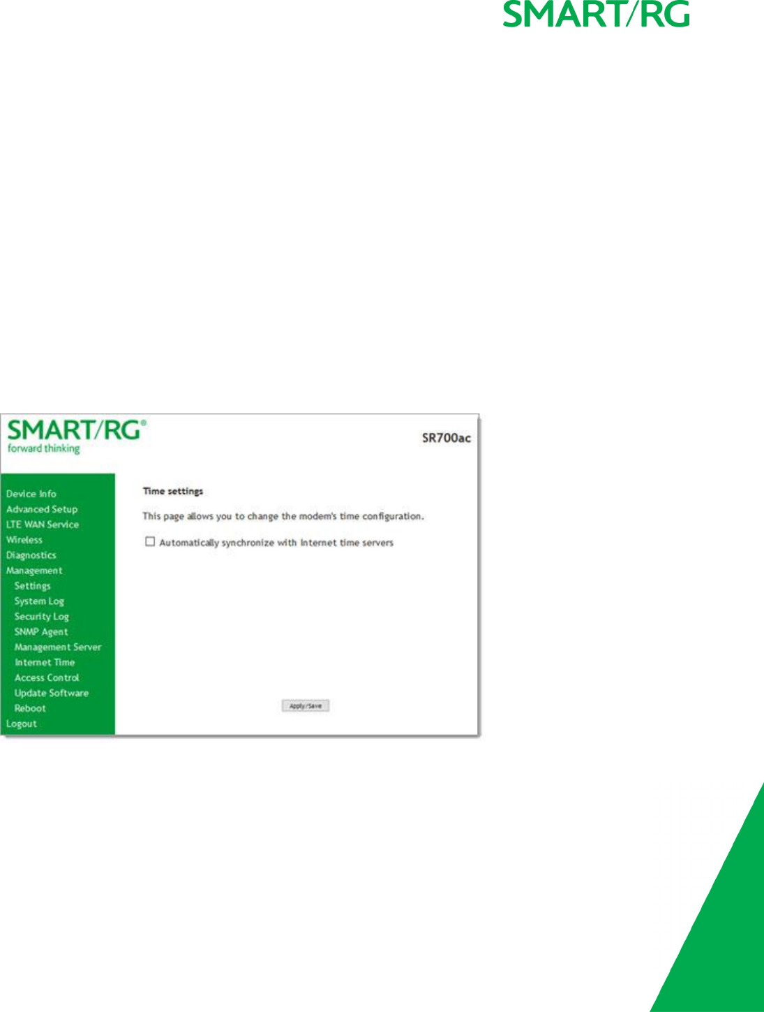
SMARTRG INC. PROPRIETARY AND CONFIDENTIAL. ALL RIGHTS RESERVED. COPYRIGHT © 2017 131
* This mechanism is used in coordination with the refreshing of NAT bindings. Specifically, in conjunction with use of Restricted Cone
NAT or Port Restricted Cone NAT (as may be configured in some gateways). A device’s internal address / port mappings, which the
STUN protocol is allowed to make use of, can have keep alive values attributed. These minimum and maximum keep alive times
define respectively, the minimum time to retain the mapping information STUN has discovered, and the maximum time to retain
that information, before refreshing it through forced re-discovery.
With the above-mentioned NAT schemes, it is possible the network address translation initially established may not be used after a
specified elapsed time. Such internal mapping is dropped. The gateway will then assign a different address mapping. This mech-
anism within the STUN protocol allows for coordinated refresh on the bindings for mappings it uses. For further information, review
STUN-related RFCs.
Selecting appropriate values for these two fields are influenced by a variety of environmental factors including devices types
deployed, services employed and NAT configuration options enabled within the topology.
Internet Time
On this page, you can synchronize the clock in your gateway with reliable external clocking servers available on the Internet.
1. In the left navigation bar, click Management >Internet Time. The following page appears.
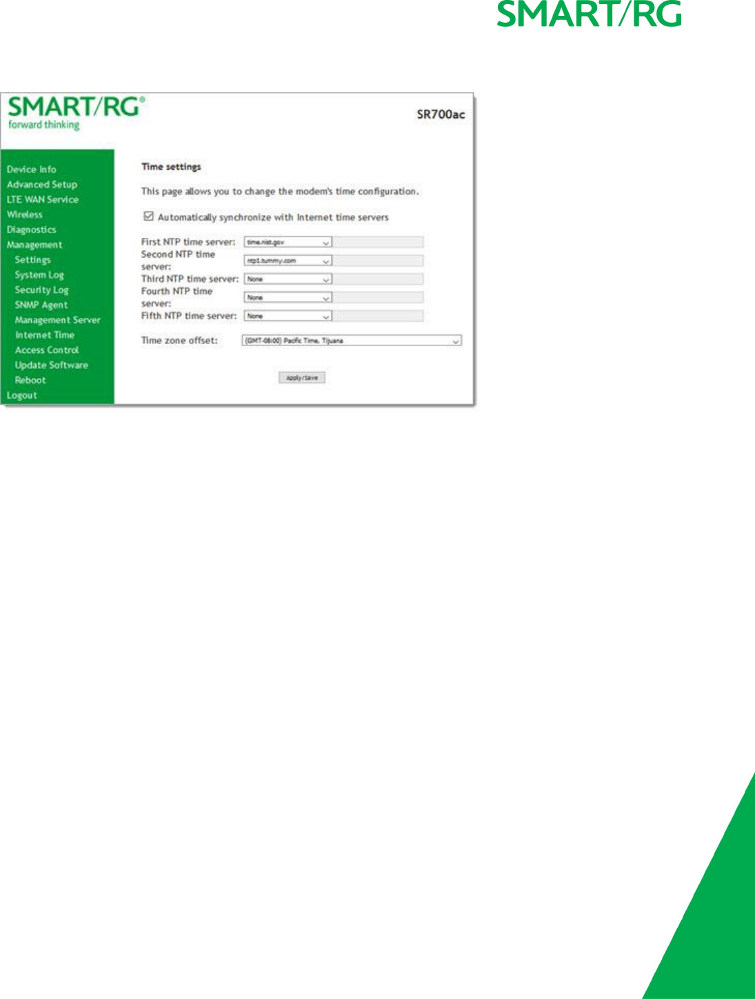
SMARTRG INC. PROPRIETARY AND CONFIDENTIAL. ALL RIGHTS RESERVED. COPYRIGHT © 2017 132
2. Click Automatically synchronize with Internet time server. A list of server fields and the Time Zone offset field appear.
3. Select servers from the list or enter your own NTP servers.
4. Select the desired time zone for the gateway.
5. Click Apply/Save to commit your settings.
Access Control
In this section, you can manage access to your gateway and network. You can configure passwords, accounts, services, access lists,
and the logout timer.
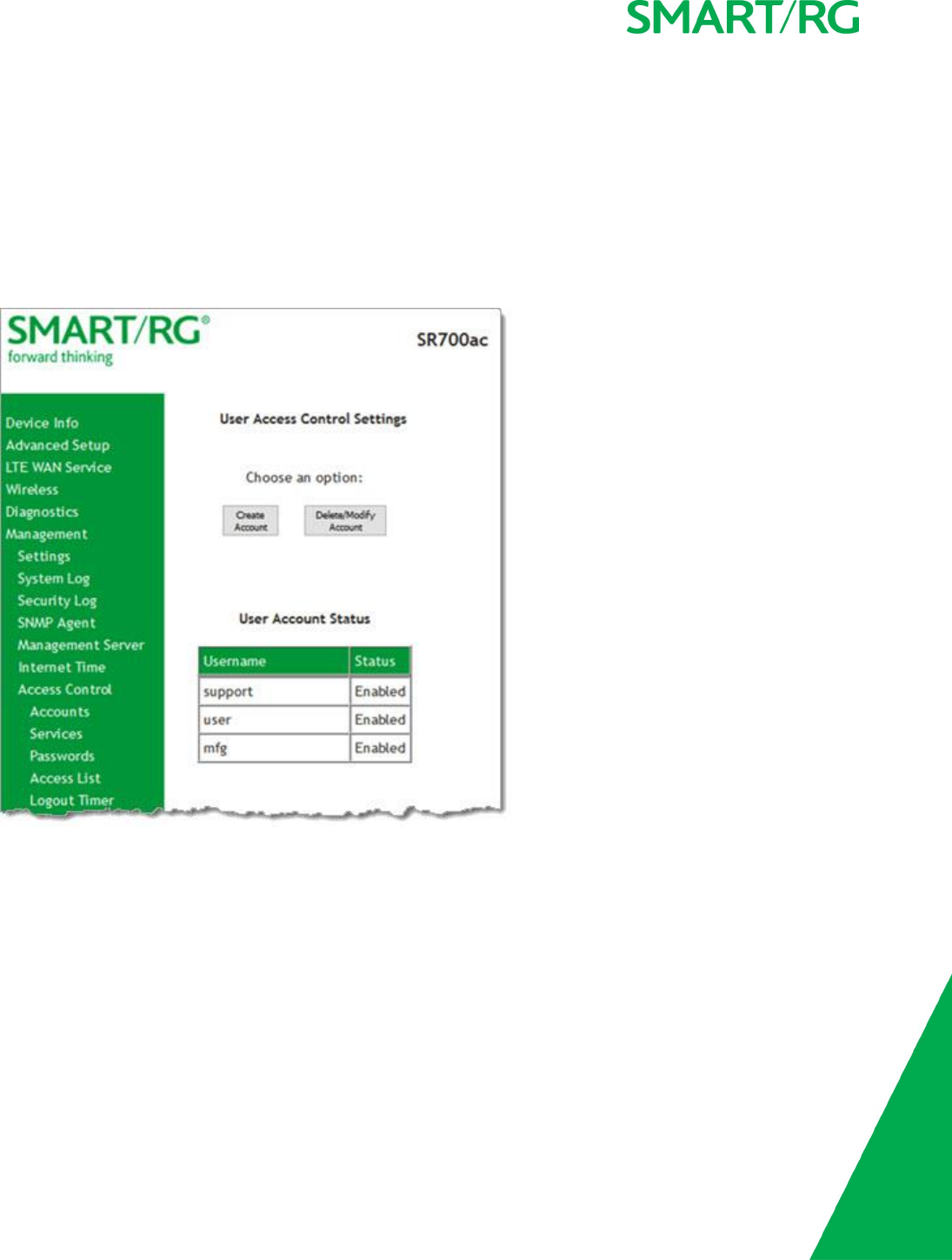
SMARTRG INC. PROPRIETARY AND CONFIDENTIAL. ALL RIGHTS RESERVED. COPYRIGHT © 2017 133
Accounts
On this page, you can create and manage user accounts for your gateway. Your gateway can support multiple login accounts for its
on-board user interface. Each account can be customized to grant access privileges to specific pages in the interface. This is par-
ticularly useful when an ISP wishes to limit access for subscribers, yet grant full access for technical support and on-site installation
personnel.
Add an Account
1. In the left navigation bar, click Management >Access Control >Accounts. The following page appears.

SMARTRG INC. PROPRIETARY AND CONFIDENTIAL. ALL RIGHTS RESERVED. COPYRIGHT © 2017 134
2. To set up a new user, click Create Account. The following page appears.
3. Enter a Username and Password for the new account.
4. Select the features that you want this user to access. If you select a subcategory, the subordinate boxes are also selected.
5. Click Save Account to commit your changes. The new account is created. To test the account credentials, log out of the
interface and then log back in using the new account.
Modify or Delete an Account
Note: While you can NOT modify or delete the default user accounts (Admin, Support, MFG, or User), you can disable the Support,
MFG, or User accounts.

SMARTRG INC. PROPRIETARY AND CONFIDENTIAL. ALL RIGHTS RESERVED. COPYRIGHT © 2017 135
You must be logged into the gateway as the Admin or Support user to modify or delete any accounts.
1. In the left navigation bar, click Management >Access Control >Accounts and then click, Delete/Modify Account. The
Delete/Edit Account page appears.
2. In the Select an account field, select the account you wish to modify or delete.
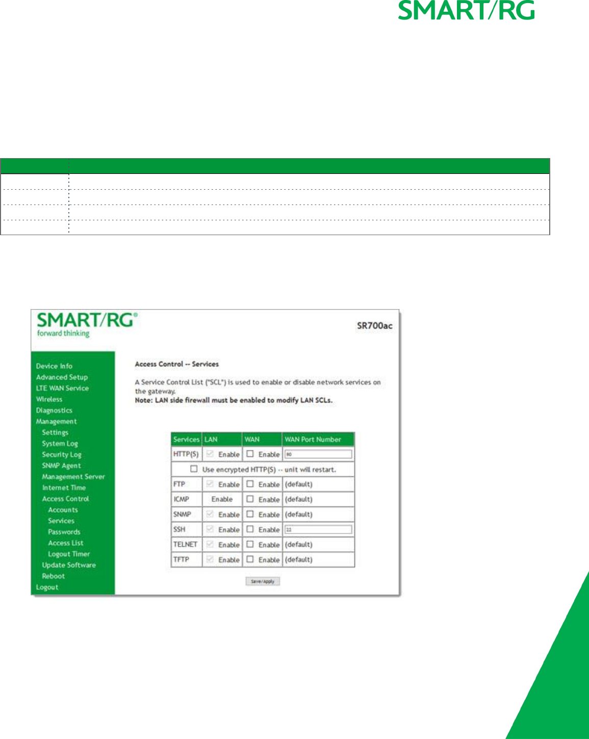
SMARTRG INC. PROPRIETARY AND CONFIDENTIAL. ALL RIGHTS RESERVED. COPYRIGHT © 2017 136
3. Do one of the following:
a. To modify an account, check or clear the desired boxes and then click Update Account to commit your changes.
b. To delete an account, scroll to the bottom of the page and click Delete Account to remove the account.
c. To disable or enable an account, click the Enable/Disable account buttons.
Your changes are implemented immediately.
Default Passwords
USER PASSWORD
admin admin
support support
user user
mfg IDH7iw@ibRsPOIBa
Services
On this page, you can define a Service Control List to control which services (FTP, HTTP, Telnet, etc.) are restricted on the LAN.
1. In the left navigation bar, click Management >Access Control >Services. The following page appears.
2. Modify settings as desired.
3. Click Save/Apply to commit your settings.

SMARTRG INC. PROPRIETARY AND CONFIDENTIAL. ALL RIGHTS RESERVED. COPYRIGHT © 2017 137
The fields on this page are explained in the following table.
Field Name Description
Services This column identifies the SCL services that can be enabled or disabled. Options
are: FTP,HTTP,ICMP,SNMP,SSH,TELNET, and TFTP.
Use encrypted HTTP(S) Click this checkbox to implement secured HTTP. This option is enabled for the LAN.
Warning: When you click this option, the gateway reboots.
LAN Select the service enabled on LAN side firewall. Depending on configuration set-
tings made elsewhere in the GUI, this column may be read-only.
Note: ICMP is an always-enabled service by default and has no checkbox.
WAN Select the service enabled on the WAN side firewall.
WAN Port Number The port the access control applies to on the WAN side for the given service. See
port information below.
Service port options
FTP FTP Service access (For WAN, this is the default port).
HTTP HTTP Service access (For WAN, this is in association with specified port. The default
is port 80.
ICMP ICMP Service access (For WAN, this is the default port).
SNMP SNMP Service access (For WAN, this is the default port).
SSH SSH Service access. For WAN, this is in association with the specified port. The
default is port 22.
TELNET TELNET Service access (For WAN, this is the default port).
TFTP TFTP Service Access (as with default port).
Passwords
On this page, you can create or change passwords associated with access to the gateway. Three accounts are available to manage:
Admin, Support and User.
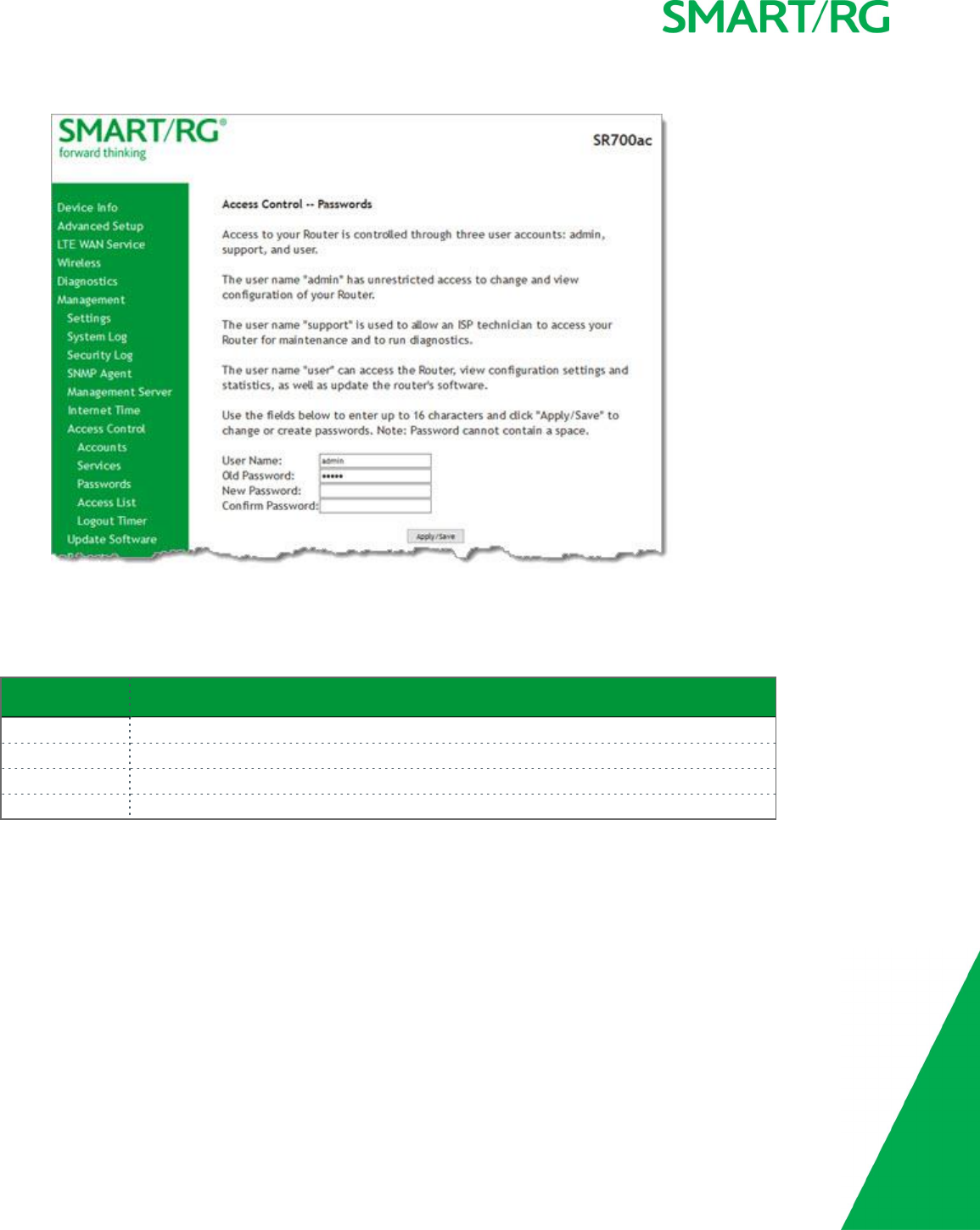
SMARTRG INC. PROPRIETARY AND CONFIDENTIAL. ALL RIGHTS RESERVED. COPYRIGHT © 2017 138
1. In the left navigation bar, click Management >Access Control >Passwords. The following page appears.
2. Enter the information for the logged-in account.
3. Click Apply/Save to commit your settings.
The fields on this page are explained in the following table.
Field Name Description
User Name Specifies name of account to be configured. Options are admin,support,user.
Old Password Enter the current password for the entered User Name.
New Password Enter the new password for the entered User Name. A maximum of 16 characters is allowed.
Confirm Password Re-enter the new password.
Access List
On this page, you can create and manage access control lists to control inbound access to specific IP addresses.
Note: This feature is available only for SR515ac models.
1. In the left navigation bar, click Management >Access Control >Access List. The following page appears showing any
addresses already configured for managed access.
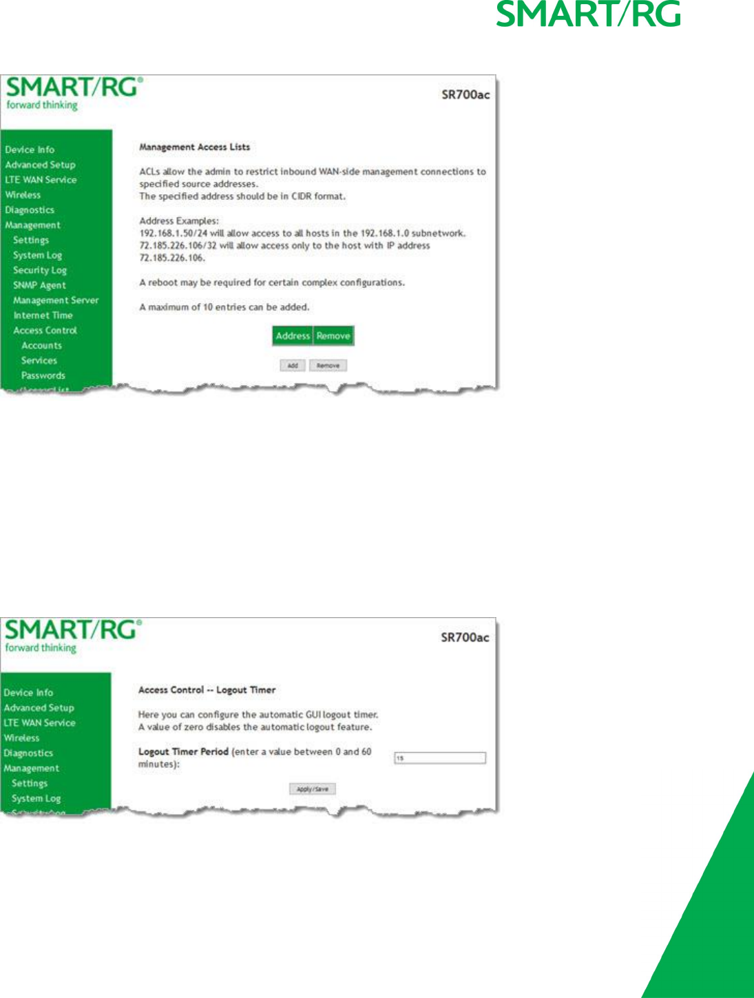
SMARTRG INC. PROPRIETARY AND CONFIDENTIAL. ALL RIGHTS RESERVED. COPYRIGHT © 2017 139
2. To add an address:
a. Click Add. The following page appears.
b. Enter the address for which you want to restrict access.
c. Click Apply/Save. You are returned to the Management AccessLists page.
d. To add up to 9 more addresses, repeat steps 2a - 2c.
3. To remove an address, click the Remove checkbox next to it and then click Remove. The list is updated.
Logout Timer
On this page, you can define the maximum time that a session can remain open before the gateway logs out.
1. In the left navigation bar, click Management >Access Control >Logout Timer. The following page appears.
2. In the Logout Timer Period field, type the number of minutes after which a session will be ended. Options are 0-60
minutes. The default is 15 minutes. To disable this feature, enter a zero (0) in the field.
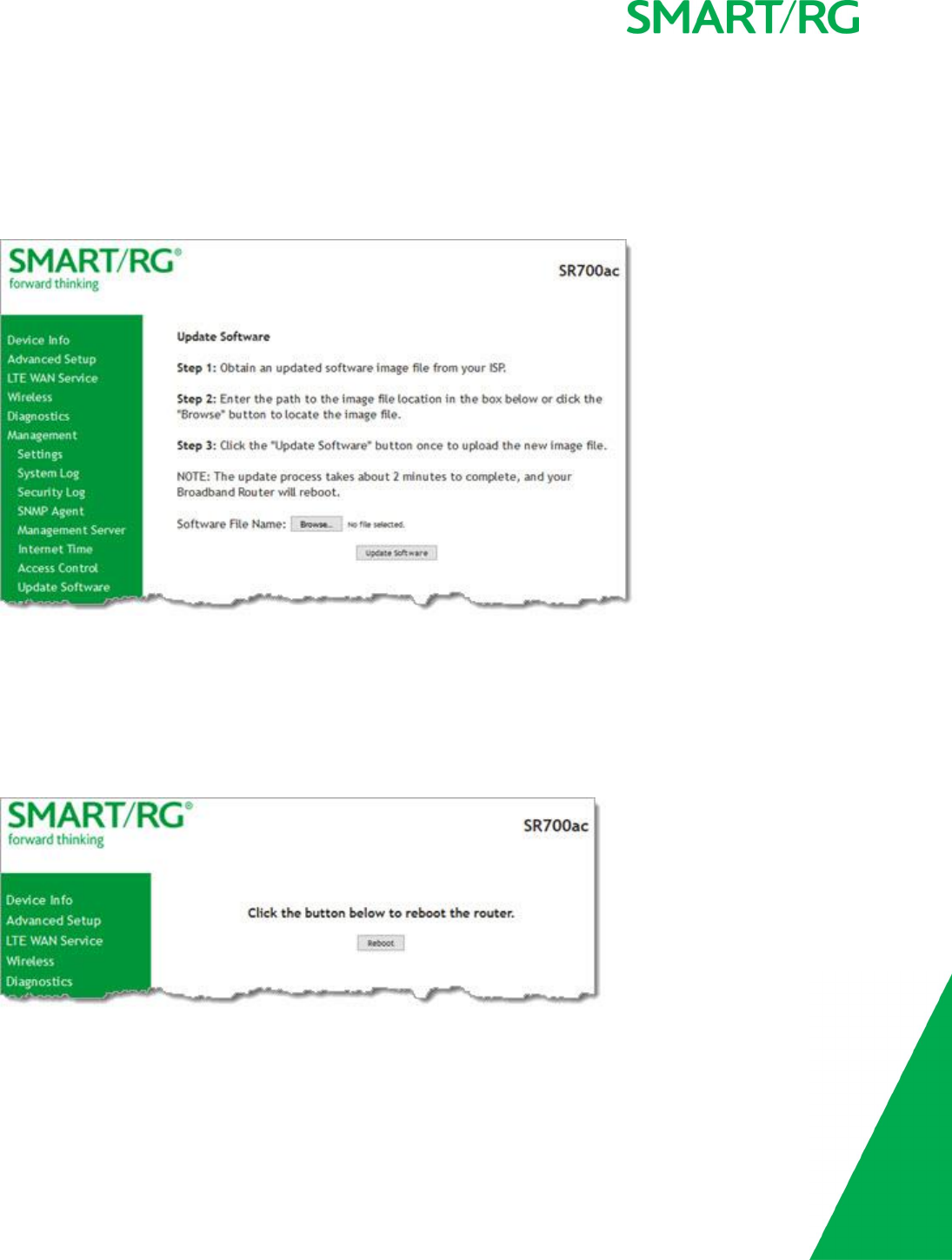
SMARTRG INC. PROPRIETARY AND CONFIDENTIAL. ALL RIGHTS RESERVED. COPYRIGHT © 2017 140
Update Software
On this page, you can update the firmware of your SmartRG gateway. Software updates for SmartRG products are available for down-
load by direct customers of SmartRG via the SmartRG Customer Portal.
1. In the left navigation bar, click Management >Update Software. The following page appears.
2. Follow the on-page instructions. When the update has completed, the gateway reboots.
Reboot
Occasionally, troubleshooting measures may require that the gateway be rebooted. On this page, you can reboot your gateway.
1. In the left navigation bar, select Management >Reboot. The following page appears.
2. Click Reboot. Your gateway is rebooted and you must log in again if you want to make further changes.

SMARTRG INC. PROPRIETARY AND CONFIDENTIAL. ALL RIGHTS RESERVED. COPYRIGHT © 2017 141
Logging Out
1. To log out of your gateway, click Logout in the left navigation menu. The Broadband Router Logout page appears.
2. Click the Logout button. A success message appears.
Appendix: Compliance Statements
FCC Interference Statement
This device complies with Part 15 of the Federal Communications Commission (FCC) Rules. Operation is subject to the following two
conditions:
lThis device may not cause harmful interference.
lThis device must accept any interference received, including interference that may cause undesired operation.
This equipment has been tested and found to comply with the limits for a Class B digital device, pursuant to part 15 of the FCC
Rules. These limits are designed to provide reasonable protection against harmful interference in a residential installation. This
equipment generates, uses and can radiate radio frequency energy and, if not installed and used in accordance with the instruc-
tions, may cause harmful interference to radio communications. However, there is no guarantee that interference will not occur in a
particular installation.
If this equipment does cause harmful interference to radio or television reception, which can be determined by turning the equip-
ment off and on, the user is encouraged to try to correct the interference by one or more of the following measures:
lReorient or relocate the receiving antenna.
lIncrease the separation between the equipment and receiver.
lConnect the equipment into an outlet on a circuit different from that to which the receiver is connected.
lConsult the dealer or an experienced radio/TV technician for help.
Caution! Any changes or modifications not expressly approved by the party responsible for compliance could void the user's author-ity to
operate the equipment.

SMARTRG INC. PROPRIETARY AND CONFIDENTIAL. ALL RIGHTS RESERVED. COPYRIGHT © 2017 142
FCC Radiation Exposure Statement
This device complies with FCC radiation exposure limits set forth for an uncontrolled environment and it also complies with Part 15
of the FCC RF Rules.
lThis equipment complies with FCC radiation exposure limits set forth for an uncontrolled environment.
lThis equipment should be installed an operated with a minimum distance of 20cm between the radiator and your body.
lThis transmitter must not be co-located or operating in conjunction with any other antenna or transmitter.
FCC - PART 68
This equipment complies with Part 68 of the FCC rules and the requirements adopted by the ACTA. On the bottom case of this equipment is a label
that contains, among other information, a product identifier in the format US: VW7DL01BSR555A.
This equipment uses the following USOC jacks: RJ-11/RJ45/USB/Power Jacks.
A plug and jack used to connect this equipment to the premises wiring and telephone network must comply with the applicable FCC Part 68 rules and
requirements adopted by the ACTA. A compliant telephone cord and modular plug is provided with this product. It is designed to be connected to a
compatible modular jack that is also compliant. See installation instructions for details.
Ringer Equivalency Number Statement
Notice: The Ringer Equivalency Number (REN) assigned to each terminal device provides an indication of the maximum number of terminals allowed
to be connected to a telephone interface. The termination on an interface may consist of any combination of devices subject only to the require-
ment that the sum of the Ringer Equivalence Numbers of all the devices does not exceed 5.
If this equipment causes harm to the telephone network, the telephone company will notify you in advance that temporary discontinuance of service
may be required. But if advance notice isn't practical, the telephone company will notify the customer as soon as possible. Also, you will be advised
of your right to file a complaint with the FCC if you believe it is necessary.
The telephone company may make changes in its facilities, equipment, operations or procedures that could affect the operation of the equipment. If
this happens the telephone company will provide advance notice in order for you to make necessary modifications to maintain uninterrupted service.
If trouble is experienced with this equipment, for repair or warranty information, please contact SmartRG,Inc. If the equipment is causing harm to
the telephone network, the telephone company may request that you disconnect the equipment until the problem is resolved.
Connection to party line service is subject to state tariffs. Contact the state public utility commission, public service commission or corporation com-
mission for information.

SMARTRG INC. PROPRIETARY AND CONFIDENTIAL. ALL RIGHTS RESERVED. COPYRIGHT © 2017 143
If your home has specially wired alarm equipment connected to the telephone line, ensure the installation of this device does not disable your alarm
equipment. If you have questions about what will disable alarm equipment, consult your telephone company or a qualified installer.
IC CS-03 statement
This product meets the applicable Industry Canada technical specifications. / Le présent matériel est conforme aux specifications techniques applic-
ables d’Industrie Canada
The Ringer Equivalence Number (REN) is an indication of the maximum number of devices allowed to be connected to a telephone interface. The ter-
mination of an interface may consist of any combination of devices subject only to the requirement that the sum of the RENs of all the devices not
exceed five. / L’indice d’équivalence de la sonnerie (IES) sert à indiquer le nombre maximal de terminaux qui peuvent être raccordés à une inter-
face téléphonique. La terminaison d’une interface peut consister en une combinaison quelconque de dispositifs, à la seule condition que la somme
d’indices d’équivalence de la sonnerie de tous les dispositifs n’excède pas cinq.
Canada Statement
This device complies with Industry Canada licence-exempt RSS standard(s). Operation is subject to the following two conditions: (1) this device may
not cause interference, and (2) this device must accept any interference, including interference that may cause undesired operation of the device.
Le présent appareil est conforme aux CNR d'Industrie Canada applicables aux appareils radio exempts de licence. L'exploitation est autorisée aux
deux conditions suivantes : (1) l'appareil ne doit pas produire de brouillage, et (2) l'utilisateur de l'appareil doit accepter tout brouillage radi-
oélectrique subi, même si le brouillage est susceptible d'en compromettre le fonctionnement.
The device meets the exemption from the routine evaluation limits in section 2.5 of RSS 102 and compliance with RSS-102 RF exposure, users can
obtain Canadian information on RF exposure and compliance.
Le dispositif rencontre l'exemption des limites courantes d'évaluation dans la section 2.5 de RSS 102 et la conformité à l'exposition de RSS-102 rf, util-
isateurs peut obtenir l'information canadienne sur l'exposition et la conformité de rf.
This transmitter must not be co-located or operating in conjunction with any other antenna or transmitter. This equipment should be installed and
operated with a minimum distance of 20 centimeters between the radiator and your body.
Cet émetteur ne doit pas être Co-placé ou ne fonctionnant en même temps qu'aucune autre antenne ou émetteur. Cet équipement devrait être
installé et actionné avec une distance minimum de 20 centimètres entre le radiateur et votre corps.
This radio transmitter (identify the device by certification number, or model number if Category II) has been approved by Industry Canada to operate
with the antenna types listed below with the maximum permissible gain and required antenna impedance for each antenna type indicated. Antenna
types not included in this list, having a gain greater than the maximum gain indicated for that type, are strictly prohibited for use with this device.
Le présent émetteur radio (identifier le dispositif par son numéro de certification ou son numéro de modèle s'il fait partie du matériel de catégorie I)
a été approuvé par Industrie Canada pour fonctionner avec les types d'antenne énumérés ci-dessous et ayant un gain admissible maximal et l'im-
pédance requise pour chaque type d'antenne. Les types d'antenne non inclus dans cette liste, ou dont le gain est supérieur au gain maximal indiqué,
sont strictement interdits pour l'exploitation de l'émetteur.
This Class B digital apparatus complies with Canadian ICES-003.
Cet appareil numrique de la classe B est conforme à la norme NMB-003 du Canada.

SMARTRG INC. PROPRIETARY AND CONFIDENTIAL. ALL RIGHTS RESERVED. COPYRIGHT © 2017 144
5GHz
5150-5350 MHz band is restricted to indoor operations only.
Revision History
REV DATE CHANGES
1.0 March 2017 Initial release.