ADTRAN TRACERT1L7 Tracer, Rack Mount User Manual 61280 003L1 1A a Front
Adtran Tracer, Rack Mount 61280 003L1 1A a Front
UserManual.wiki
>
ADTRAN
>
TRACERT1L7 User Manual
>
Updated User Manual
Contents
1.
Instruction Manuals
2.
Updated User Manual
Updated User Manual
Navigation menu
Upload a User Manual
Namespaces
Wiki Guide
HTML
PDF
Info
Views
User Manual
Discussion / Help
Navigation

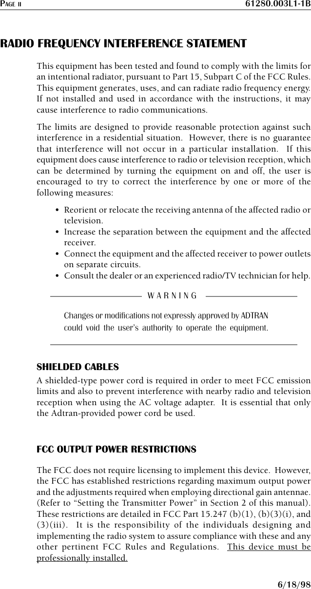

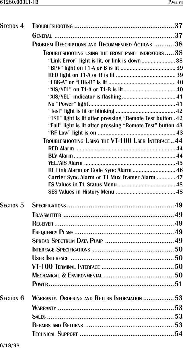

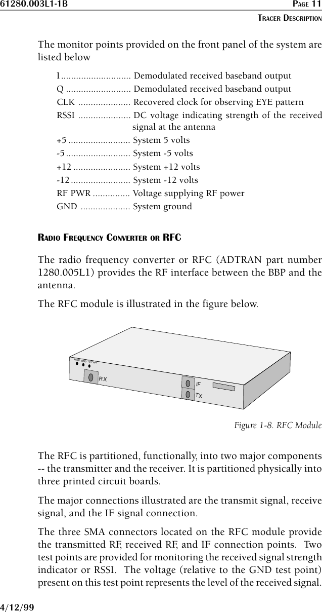
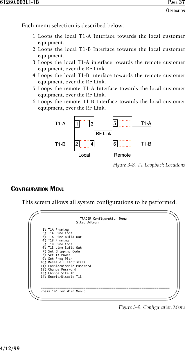
![PAGE 12 61280.003L1-1B4/12/99This signal is used to align the antenna during installation and toverify that the link is performing as designed. A third test point isprovided to monitor the transmitter output power during systemconfiguration.The only connections that must be made in the field are a coaxconnection between the BBP and the RFC and a coax connectionbetween the RFC and the antenna.The “IF” connector provides the connection between the BBP andthe rack or mast-mounted RFC. (A blue 6-inch IF cable [ADTRANpart number 3125.001@A] is provided for rack-mount systems.ADTRAN does not provide IF cable for mast-mount systems.) The“ANTENNA” connector provides the connection between the RFCand the antenna.A block diagram of the RFC functions is shown in the figure below.20182058SAW33323212281AGCSplitterSplitterAGCPALPFRF2IF20182058TxRxFigure 1-9. RFC Function Block DiagramThe RFC unit is enclosed in a metal housing measuringapproximately 10.5" x 5.5" x 1" and may be mounted in a 1-Unineteen-inch rack space or in a weather-tight enclosure suitableSECTION 1](https://usermanual.wiki/ADTRAN/TRACERT1L7.Updated-User-Manual/User-Guide-32103-Page-22.png)

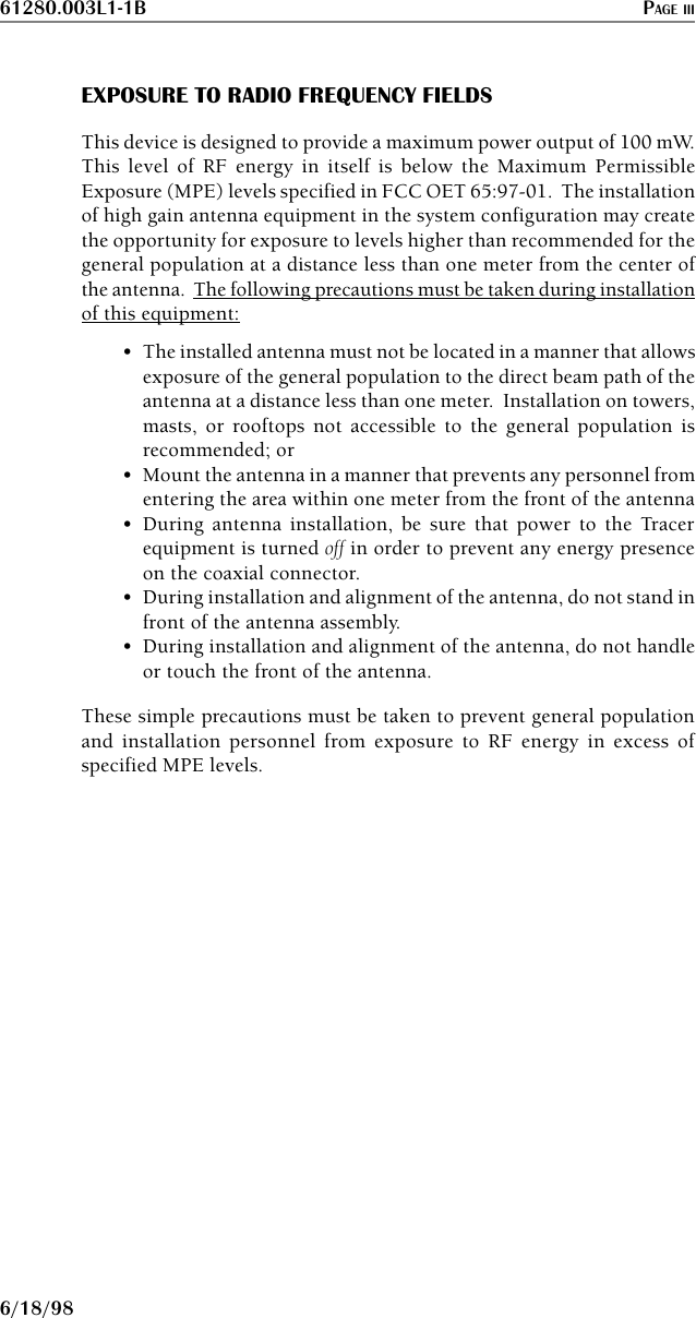
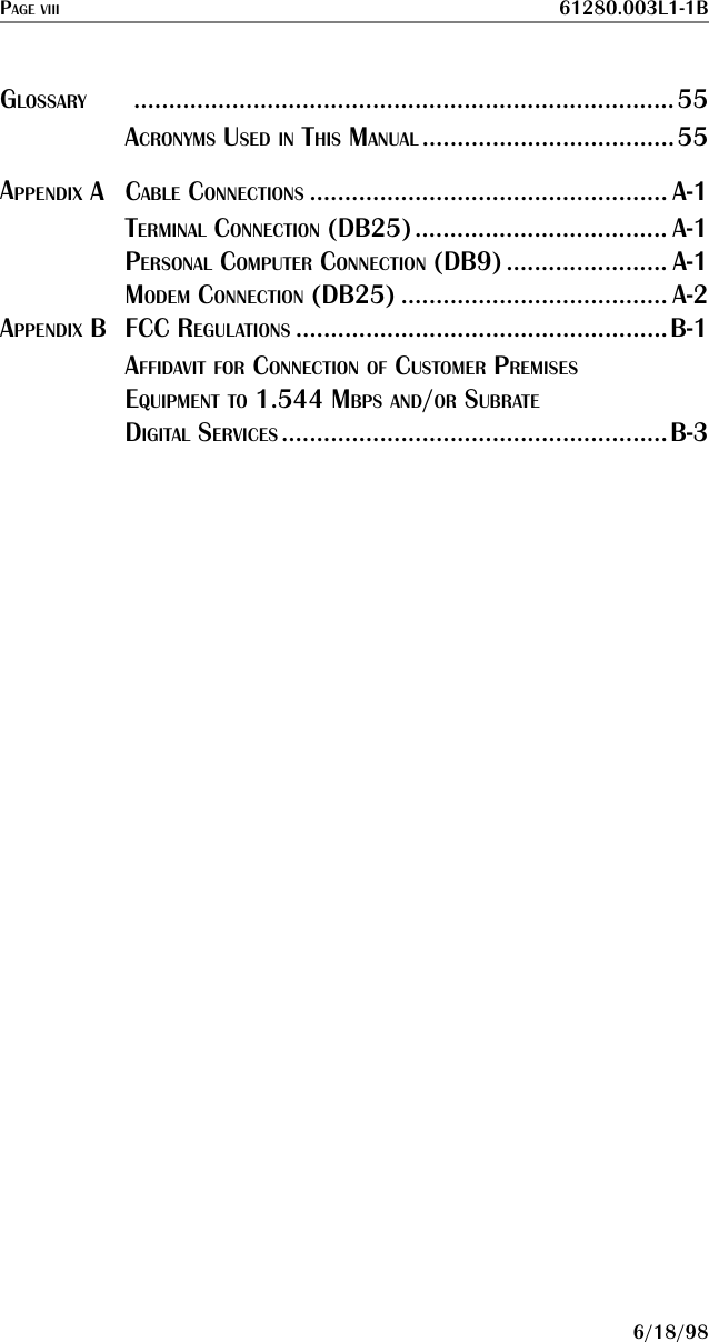
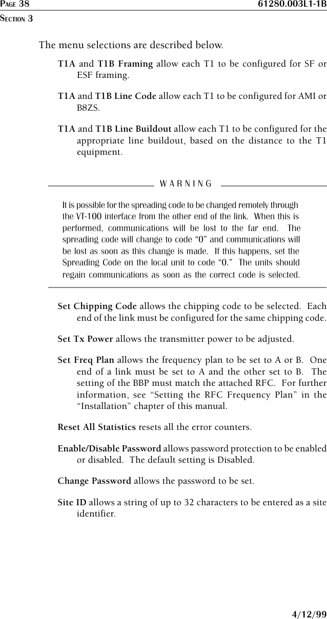
![61280.003L1-1B PAGE 334/12/99MAIN MENU SELECTIONSSYSTEM STATUS PAGEThis page displays the status of major system components. Thisis a status screen only; no configurations can be performed. Moredetailed information can be obtained by way of the Main Menu. Current System Status Elapsed Time 00:14:59 ____ ADTRAN Technical Support - 800/726-8663 ____T1A ===| |-------------------[RF UP]-------------------->| |=== T1A | | | |T1B ===| |<------------------[RF UP]---------------------| |=== T1B ---- ---- Local Tracer Remote Tracer Freq Plan A Freq Plan B Tx Pwr Rx Pwr Tx Pwr Rx Pwr+20dBm[X] [X] Nominal +20dBm[X] [X] Nominal [X] [X] [X] [X] [X] [X] Site: ADTRAN [X] [X] [X] [X] [X] [X] [X] [X] Code Sync: Yes [X] [X] [X] [X] Carrier Sync: Yes [X] [X] [X] [X] T1 Mux Sync: Yes [X] [X] [X] [X] Chipping Code: 9 [X] [X] [X] [X] [X] [X] [X] [X] [X] [X]-15dXm[X] [X] Minimum -15dBm[X] [X] Minimum=======================================================================Press ‘m’ for Main Menu:Figure 3-1. System Status PageThe upper portion of the screen indicates how long the systemhas been running since the last reset operation. The “T1A” and“T1B” labels will be highlighted if any error conditions exist onthat T1 interface.The status of the radio link is indicated as Up or Down. The leftportion of the screen reports the status of the local system (thesystem to which the terminal is attached); the right portion reportsthe status of the remote system. The approximate transmitterand receiver signal levels are shown via the “fuel gauges.” If thelink is down and remote end data is unavailable, the fuel gaugeswill show “-” instead of “x.” The Code Sync, Carrier Sync, and T1Mux Sync will all be “yes” for an operational link. Chipping codeindicates the code to which the system is set. At any point in theVT-100 menu structure, pressing the Escape key will bring theoperator back to this screen.OPERATION](https://usermanual.wiki/ADTRAN/TRACERT1L7.Updated-User-Manual/User-Guide-32103-Page-43.png)


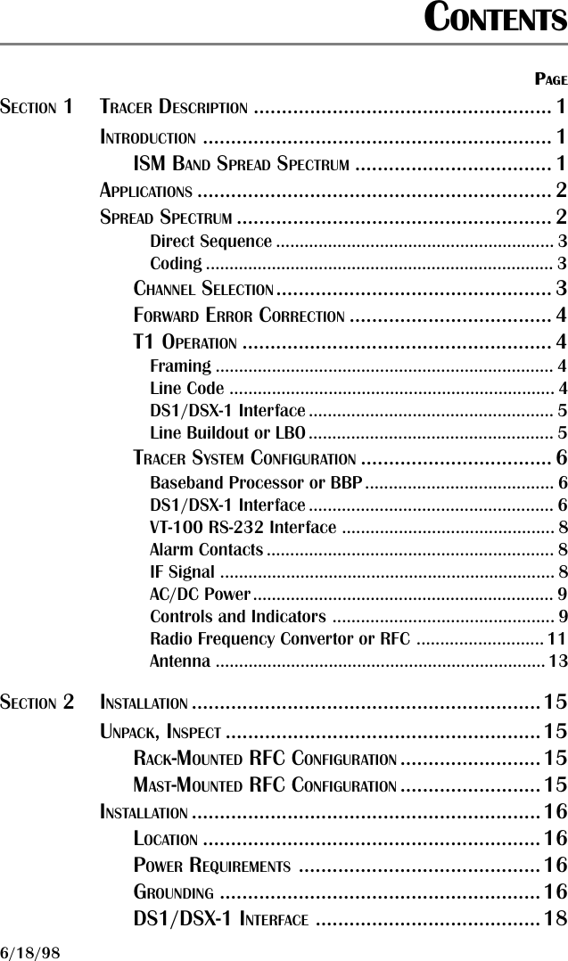
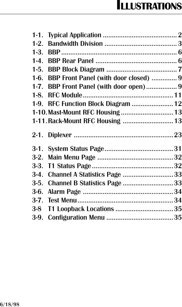
![61280.003L1-1B PAGE B - 3FCC REGULATIONS4/12/99AFFIDAVIT FOR CONNECTION OF CUSTOMER PREMISES EQUIPMENT TO1.544 MBPS AND/OR SUBRATE DIGITAL SERVICESFor the work to be performed in the certified territory of__________________________________________________________(TELCO NAME)State of ______________________________________________County of ____________________________________________I, _____________________________________________________(NAME)_________________________________________________________(BUSINESS ADDRESS)___________________________________ being duly sworn, state:(TELEPHONE NUMBER)I have responsibility for the operations and maintenance of theterminal equipment to be connected to 1.544 Mbps and/or subratedigital services. The terminal equipment to be connected complieswith Part 68 of the FCC rules except for the encoded analogcontent and billing protection specifications. With respect toencoded analog content and billing protection:[ ] I attest that all operations associated with the establishment,maintenance, and adjustment of the digital CPE with respect to analogcontent and encoded billing protections information continuouslycomplies with Part 68 of the FCC Rules and Regulations.[ ] The digital CPE does not transmit digital signals containing encodedanalog content or billing information which is intended to be decodedwithin the telecommunications network.[ ] The encoded analog content and billing protection is factory set andis not under the control of the customer.](https://usermanual.wiki/ADTRAN/TRACERT1L7.Updated-User-Manual/User-Guide-32103-Page-73.png)
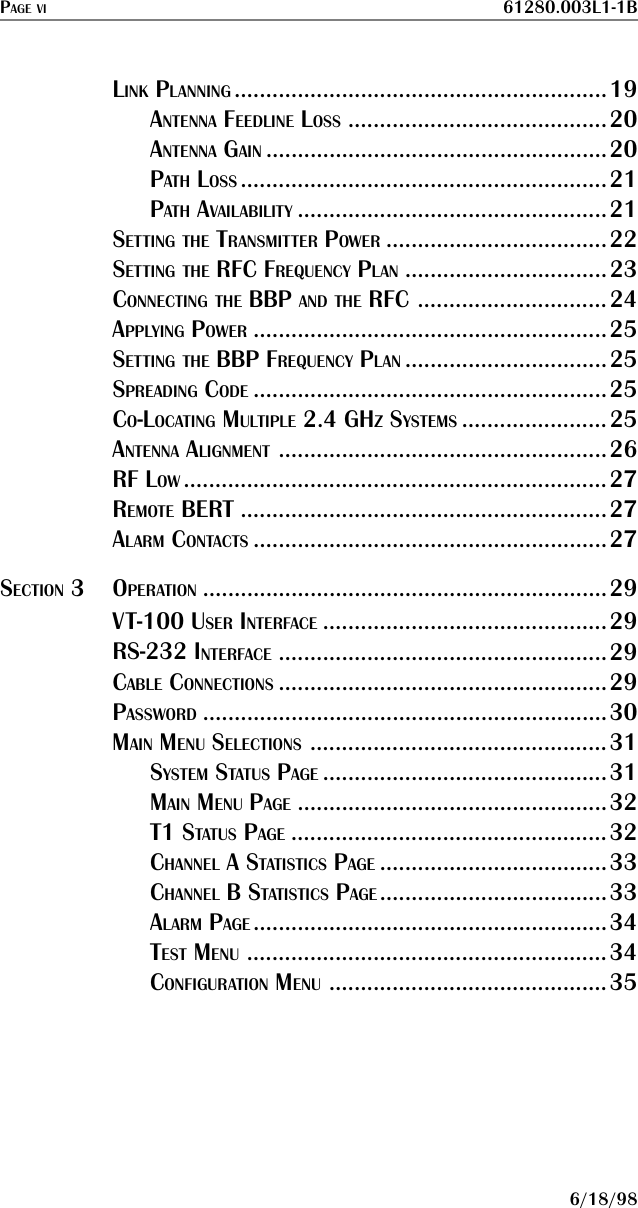
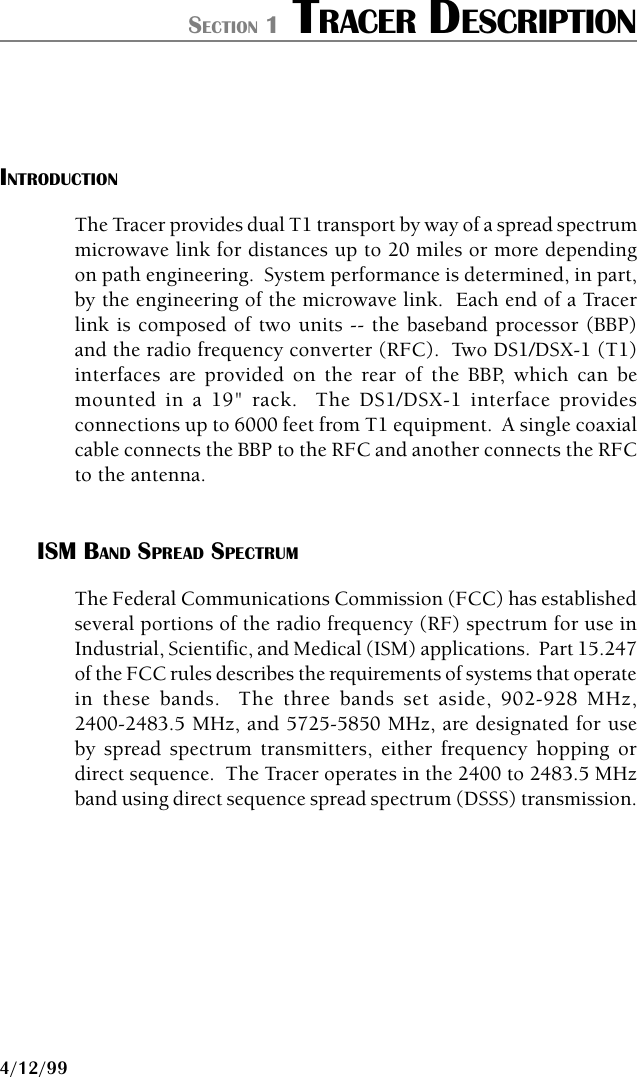
![PAGE B - 4 61280.003L1-1BAPPENDIX B4/12/99I attest that the operator(s)/maintainer(s) of the digital CPEresponsible for the establishment, maintenance, and adjustmentof the encoded analog content and billing information has (have)been trained to perform these functions by successfully havingcompleted one of the following (check appropriate blocks):[ ] A. A training course provided by the manufacturer/grantee of theequipment used to encode analog signals; or[ ] B. A training course provided by the customer or authorizedrepresentative, using training materials and instructions provided by themanufacturer/grantee of the equipment used to encode analog signals;or[ ] C. An independent training course (e.g., trade school or technicalinstitution) recognized by the manufacturer/grantee of the equipmentused to encode analog signals; or[ ] D. In lieu of the preceding training requirements, the operator(s)/maintainer(s) is (are) under the control of a supervisor trained inaccordance with (CIRCLE ONE) above.I agree to provide ________________________________________(TELCO NAME)with proper documentation to demonstrate compliance with theinformation as provided in the preceding paragraph, if sorequested.______________________________________________________(SIGNATURE)______________________________________________________(TITLE)______________________________________________________(DATE)Transcribed and sworn to before methis __________ day of _______________, ________________________________________________________________(NOTARY PUBLIC)My commission expires ___________________________________](https://usermanual.wiki/ADTRAN/TRACERT1L7.Updated-User-Manual/User-Guide-32103-Page-74.png)