AEE Wireless Technology NC601 2.4GhZ Color Wireless MEPG-4 Video Network Camera User Manual
Shenzhen AEE Wireless Technology Co., Ltd. 2.4GhZ Color Wireless MEPG-4 Video Network Camera
Manual
Please read this manual carefully and thoroughly before any attempt to
install and operate this product and retain it for your future reference.
User's Manual
2.4GHz Color Wireless
MPEG-4 Video Network Camera
MODEL: NC601
English
R

EU Environmental Protection
Waste electrical products should not be disposed of with
household waste. Please recycle where facilities exist.
Check with your Local Authority or retailer for recycling
advice.

IP Finder Installation
Network Parameters
29~49
INTRODUCTION 1~5
Maintenance 3
Restrictions 2
Copyright 2
Warranty 2
Notice 1
Package Contents 6
Camera Feature Locations 7
6~8
PRODUCT
UPnP Function 18~21
17
15~16
Proxy Server Setting
13~14
Network Camera Configuration Type 11~12
Network Camera Installation 9~10
PREPARATION 9~24
Adapter 8
Approval Information (FCC/CE)1
TABLE OF CONTENTS
PC System Requirements 8
Internet Explorer Security Setting 21~23
Set the Network Camera as Virtual Server 23
Power on the Network Camera 24
NETWORK CAMERA SCREEN AND SETUP WINDOW 25~51
Main Features 4~5
Network Camera Setting Interface
Operating Bar
Misc Setup
Date & Time
User Management
System Identity
FTP Setup
E-mail Setup
Motion Detection Setup
UPnP Setup
DDNS Setup
PPPoE Setup
Ethernet Setup
Wireless Setup
Pan/Tilt Setup
Camera Setup
27~28
Firmware Upgrade
Backup or Reset
48~49
47
46
45
43~44
42
41
40
39
38
35~37
34
33
32
31
30
CAMERA
NETWORK
ALARM
TOOLS
25-26
Review images from the Network Camera

50
GLOSSARY 56
TROUBLESHOOTING 55
SPECIFICATIONS 54
52~53
System Information
Reboot System
Wizard
Support
50
51
51
50~51
Speedread your Network Camera
DEFAULT SETTINGS

INTRODUCTION
Thank you for your interest and support in our product and purchasing this wireless home network camera.
This product
eel confident that you will be pleased with the quality and features of this product.
works at ISM-2.4GHz frequency band, which could be legally used worldwide without
permission. We f
Notice
This product may cause interferences with other wireless equipment that operates at 2.4GHz ISM band.
Please turn off one of the equipments to eliminate the interference.
Product Assurance
This camera will emit electromagnetic wave, just like other wireless products. But its transmitting power is
lesser than other wireless products such as mobile phones. The 2.4GHz wireless camera meets wireless
frequency security standards and recommended indexes while working. These standards and indexes are
certificated by academic organization and represent the cogitative research of the scientific workers who
continuously explore and annotate the involved fields. So we believe that our products are safe for
customers.
1
All our products meet the requirements of approval FCC or CE, and are granted the FCC or CE
certification. They are authorized to bear FCC or CE mark.
Approval Information
After testing the product, we confirm that it complies with the provision for class C digital equipment in the
15th part in FCC regulation; and the receiver complies with the limitations for class B digital equipment in
Part 15 of FCC regulation. The product generates, applies and emits radio waves. It might cause harmful
interferences to wireless communication if not be installed and used following the description of the manual.
The product may cause interference in residential area, and the customer should take remedies to
eliminate the interference at their own costs. If the product causes any harmful interference to wireless
equipment or disturbs the receiving of TV signals (it can be identified by turning on and off the product),
you can solve the trouble by following methods:
FCC
This product complies with standards including Low Voltage Device Directive 73/23/EEC; EMC
Directive 89/336/EEC and R&TTE Directive 1999/5/EC. It passed the subject tests by the authority
concerned and is authorized to bear CE mark.
CE
This product meets the requirements specified in Part 15 of FCC Regulation. Operation rests with the
following two conditions:
(1) The equipment should not cause any harmful interference;
(2) The equipment must receive and process any interference, including any possible interference caused
by operation mistakes.
(1) Readjust the product or put it in another place;
(2) Extend the distance between the equipment interfered and the product; and
(3) Refer to dealers or experienced radio electrician for help.

Copyright
This manual is furnished under license and may be used or copied only in accordance with the terms of
such license. Except as permitted by such license, no part of this publication may be reproduced, stored in
a retrieval system, or transmitted, in any form or any means, electronic, mechanical, recording, or
otherwise, including translation to another language or format, without prior written permission of AEE
Technology.
Warranty
AEE Technology warrants that this product will be free from defects in materials and workmanship for
period of time specified. This limited warranty shall commence from the date of purchase. AEE Technology
product's warranty is not transferable and is limited to the original purchaser. If the product is found to be
defective then, as your sole remedy and as the manufacturer's only obligation, AEE Technology will
repair or replace the product.
2
This warranty shall not apply to products that have been subjected to abuse, misuse, abnormal electrical
or environmental conditions, normal wear and tear or any condition other than what can be considered
normal use.
Should you have problems, please consult the local dealer.
The content of this manual is furnished for informational use only, is subject to change without notice, and
should not be construed as a commitment by AEE Technology.
AEE Technology assumes no responsibility or liability for any errors or inaccuracies that may appear in this
booklet. All other product names, trademarks and registered trademarks in this document are the
properties of their respective holders.
1. DO NOT use this product to violate one's privacy. Monitoring one's activities without consent is illegal
and this product is not designed and manufactured for such purpose;
2. DO NOT put this product near any medical equipment. Radio waves might potentially cause breakdown
of electrical medical equipment.
So this product should be placed at least 1 feet away from any heart pacemaker. Radio waves might
potentially influence heart pacemaker and lead to respiratory disturbance;
3. DO NOT use this product for any illegal activities. AEE Technology shall not be responsible for any
consequences of illegal acts committed by the user.
Restrictions

1. Ensure the sufficient ventilation space is available;
2. Do not shake or strike the product;
3. Keep it dry and dustless and avoid exposing it to direct sunlight;
4. Do not place the product near any magnetic objects;
5. Avoid putting the product in places where the constantly changed temperature or humidity occurs;
6. Keep the product away from heat sources such as electric heater;
7. Do not use the camera near aggressive chemicals;
8. Do not use this camera near water, for example, near a bath tub, wash bowl, kitchen sink or laundry
tub, in a wet basement or near a swimming pool and the like;
9. Do not use the camera in the places which are enclosed by metal. The surrounding metal like lifter,
cabin, may shield the electromagnetic wave, and result in failure of signal reception;
10. Please obey the local government's environment protection policy;
11. Please turn off the power when left unused;
12. Do not disassemble or repair the camera; doing so might cause damages to the product.
Maintenance
3

MAIN FEATURES
Easy Installation
The Network Camera NC601 comes with built-in CPU and
No need to install the driver for the NC601. Setup CD-ROM includes the IP Finder software and Operation
Instruction. Insert the Setup CD-ROM and auto run program should start the application automatically.
With industry standard automatic configuration-UPnP(Universal Plug and Play), the NC601 and your router
or PC will automatically decide the best settings allowing you to access your NC601 without any
complicated setup. Once connected, using a simple Web browser, just enter in your free, permanent Web
address which comes with the NC601 and you can see and move the NC601!
The NC601 can be either wall-mounted or ceiling-mounted with the fixing plate or placed on a desktop
using the supplied camera stand, providing flexible installation to meet your specific needs.
802.11b/g Wireless LAN Connection Available
The NC601 is designed to not only work with your existing wired network but also can be compatible with
standard 802.11b/g wireless devices, allowing the flexibility to install and operate the NC601 without
running network wire, and utilizing SSID filtering and powerful 64/128 bit WEP encryption helps to protect
your wireless network from illegal intrusion. NC601 can work compatibly with 802.11b, 802.11g and
802.11b/g modes.
High-Speed MPEG4
The NC601 has an integrated web server. MPEG4 displays up to 30 frames per second, if the network
provides enough bandwidth. To conserve bandwidth, MPEG4- Regularly Refresh can be selected from Top
Page.
Remote Pan / Tilt Control
Web-based viewing with remote pan and tilt functions lets you adjust the NC601 angles from a computer in
another location.
Multi-Client Access
The NC601 allows up to 10 users to view MPEG4 image simultaneously. Users can access the Top View
Image screen from their own locations. Note that as the number of users simultaneously connected to
NC601 increases, the overall motion performance will decrease.
Audio Transmission
The NC601 comes with built-in microphone and external microphone input jack, for audio monitoring as
well as video monitoring. Sound captured by your NC601 can be transmitted to the client’s PC. The
external microphone greatly enhances the ability to pick up the desired sound.
, Wireless Net Card (IEEE802.11b/g) Web Server.
4

5
Motion Detection Function
The NC601 can detect the change of picture being monitored. Once anything happens, it will email to your
designated email addresses (maximum 3) and send the picture captured to designated FTP server. You
could receive message and take action immediately when an alarm triggered.
Authentication
Authentication window requires you to enter the administrator/general user ID and password. Password
security can prevent unregistered users/intruders from accessing your image from their web browsers.
6
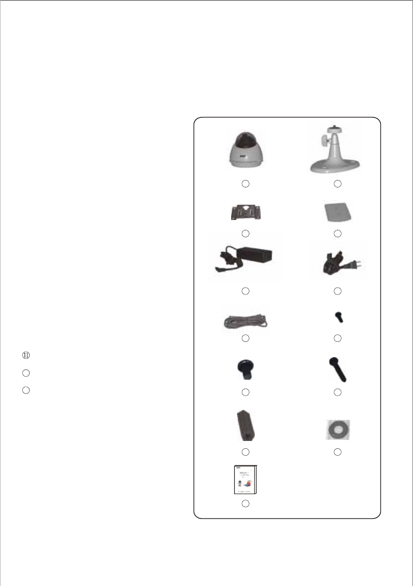
This package comes with the following items. Please check whether they are all included in the packaging
box, if one or some is missing, contact the retailer for replacement.
Package Contents
PRODUCT
Notes:
1. This product can be either black or silver.
2. The pictures may vary from the actual objects.
① Network camera 1
② Universal Bracket 1
③ Metal mounting plate (1) 1
④ Plastic mounting plate (2) 1
⑤ Power adaptor 1
⑥ Power adaptor cable 1
⑦ Network cable 1
⑧ Plastic screw 2 (M3 10)
⑨ Mechanical bolt 1 (M6 16)
⑩ Mechanical bolt 4 (M4 30)
Anchor for screw 4
CD-ROM 1
User's manual 1
×
×
×
×
×
×
×
××
××
××
×
×
×
12
13
12
3 4
56
78
910
11 12
13
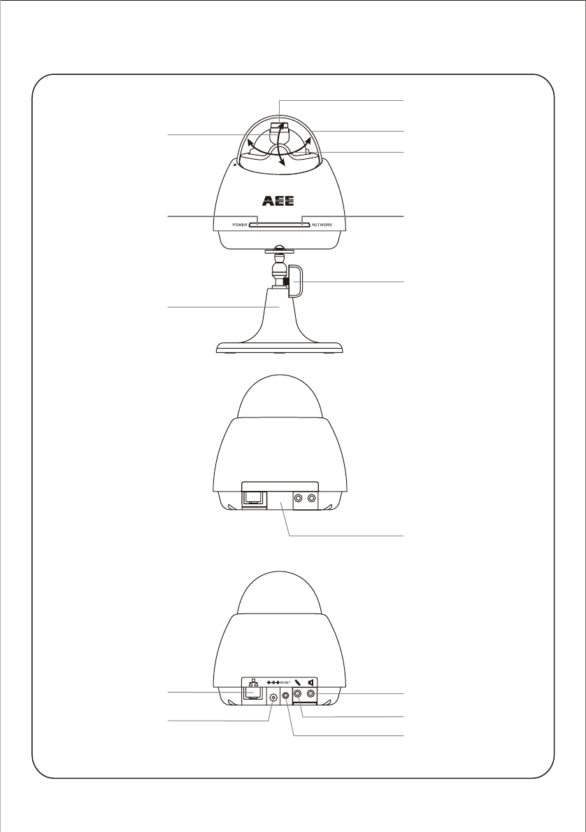
Camera Feature Locations
7
Transparent Cover
Lens
Network LED
Universal Bracket
Speaker Output
Microphone Output
Reset Button
DC Power Jack
Network Cable Jack
Power LED
o o
Pan: -65 ~ +65
o o
Tilt: -35 ~ +35
Shield Cover
Fastener
8
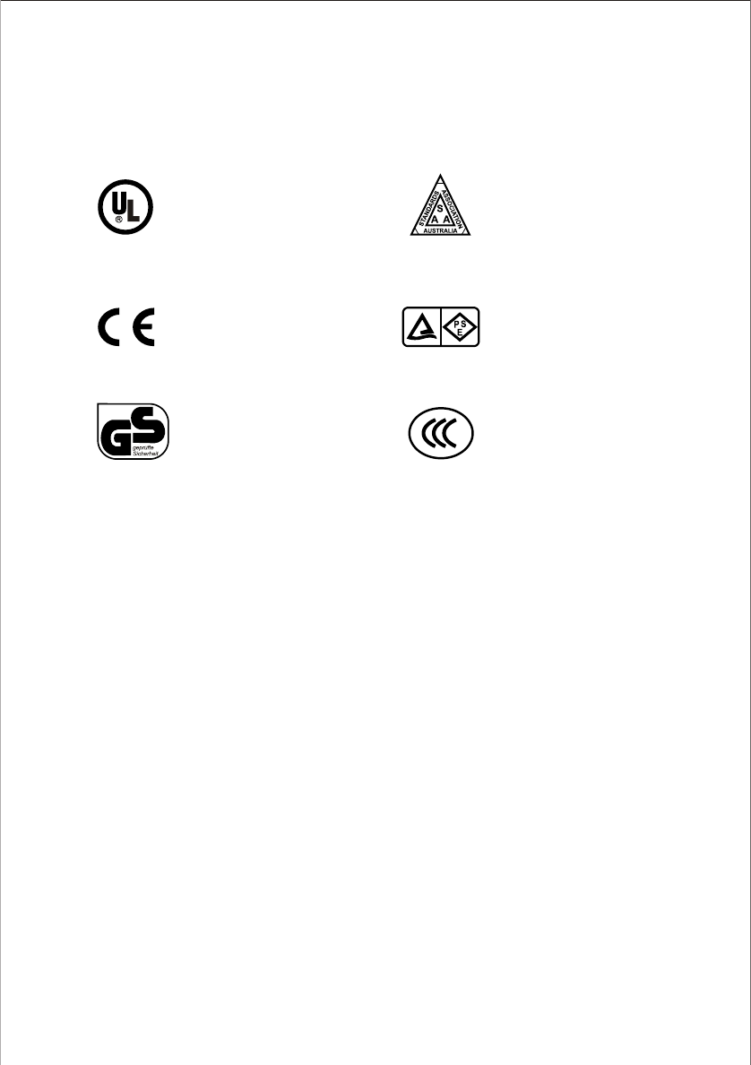
This product always conforms to the authenticated AC adapter. The adapter should be marked one of the
following:
Note:
When using the power adapter, make sure the rating voltage on it is compatible with that of the device to avoid potential
damages resulting from incorrect usage of power supply.
Adapter
UL Mark
American power
supply authentication
SAA Mark
Australia power
supply authentication
GS Mark
German power
supply authentication
CCC Mark
China power
supply authentication
European Union power
supply authentication
CE Mark PSE Mark
Japan power
supply authentication
The PC (Personal Computer) and the network must meet the following technical specifications for NC601
to work properly.
PC System Requirements
1. Processor:
2. RAM: 128 MB or more
. OS( : Windows 2000/XP
. Web Browser: Internet Explorer Version 5. or
NC601
Intel Pentium III, 800MB or Higher (Pentium IV, 2 GHz or Higher
recommended)
3. Color Monitor: Suggest at least 800x600 and the latest driver for the Display Adapter
4 Operating System)
5 0 above (DirectX 8.1 or later)
6. Network Protocol: TCP/IP network protocol installed.
7. Interface: 10/100 Mbps Ethernet® card for your network connection
Note: The comes with setup CD-ROM, suggest the CD-ROM Drive available to install the IP Finder software.
PREPARATION
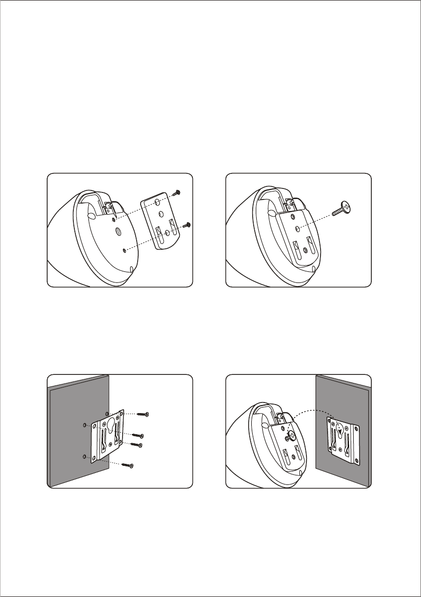
Network Camera Installation
The NC601 can be located on the wall or ceiling. Please follow the steps below to install NC601.
1. Mounting without the universal bracket
The NC601 can be mounted on the wall or ceiling with the mounting plate directly.
1.1 Locate the plastic mounting plate to the NC601 with screws.
1.2 Drill four holes on the mounting surface according to holes in the metal mounting plate. Insert the
anchors into the holes, then align the metal mounting plate with the holes you just drilled and drive the
screws through the metal mounting plate into the anchors, then hang the NC601 on the metal mounting
plate firmly.
9
s
s
e
l
e
r
i
w
s
s
e
l
e
r
i
w
s
s
e
l
e
r
i
w
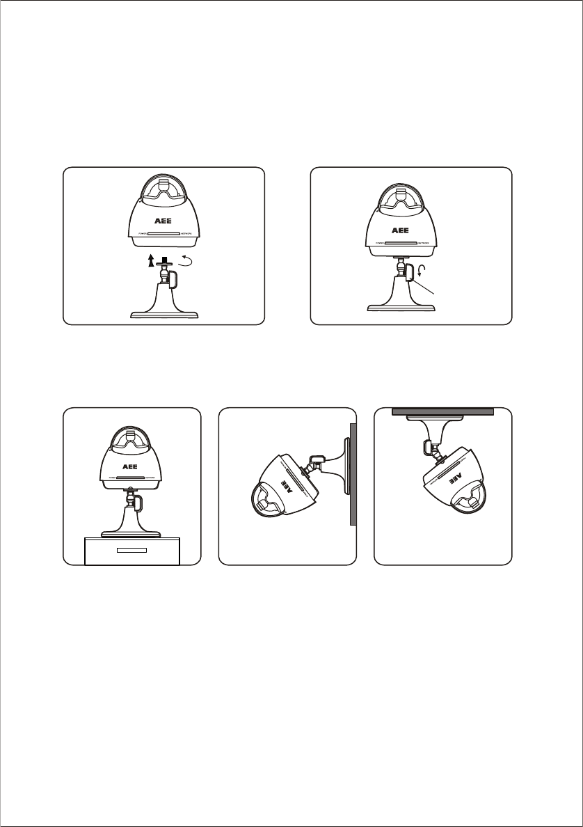
2. Mounting with the universal bracket
The NC601 can be mounted on the wall, ceiling or desktop with the universal bracket.
2.1 Connect the universal bracket to the NC601 firmly. Yo u can adjust the Network Camera NC601 to a
suitable angle by rotating the fastener.
2.2 Locate your NC601 on the wall, ceiling or desktop.
Fastener
10
In this mode, connect the NC601 to the Wireless AP (Access Point) with Network cable.
In this connection mode, connect the Network Camera NC601 to the Wireless Network PC directly.
Wireless Network PC
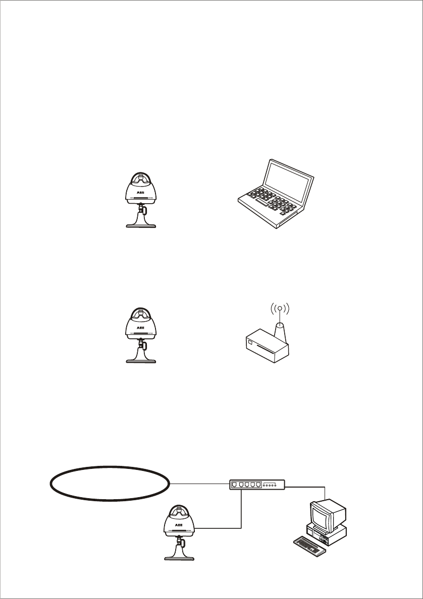
The NC601 can be connected over the LAN/Intranet and the Internet. Select from the NC601 configuration
types. Network parameters differ depending on the Network Camera NC601 configuration type.
Network Camera Configuration Type
Type 1. Adhoc connection mode
Wireless Network
Type 2. Infrastructure connection mode
Wireless AP
Wired Network
The NC601 can be installed on the LAN/Intranet by the Ethernet switcher/ hub.
Type 1. LAN/Intr anet Connection with an Ethernet Switcher/ Hub
LAN/Intranet
Ethernet Switcher/ Hub
11
Network Camera NC601
Network Camera NC601
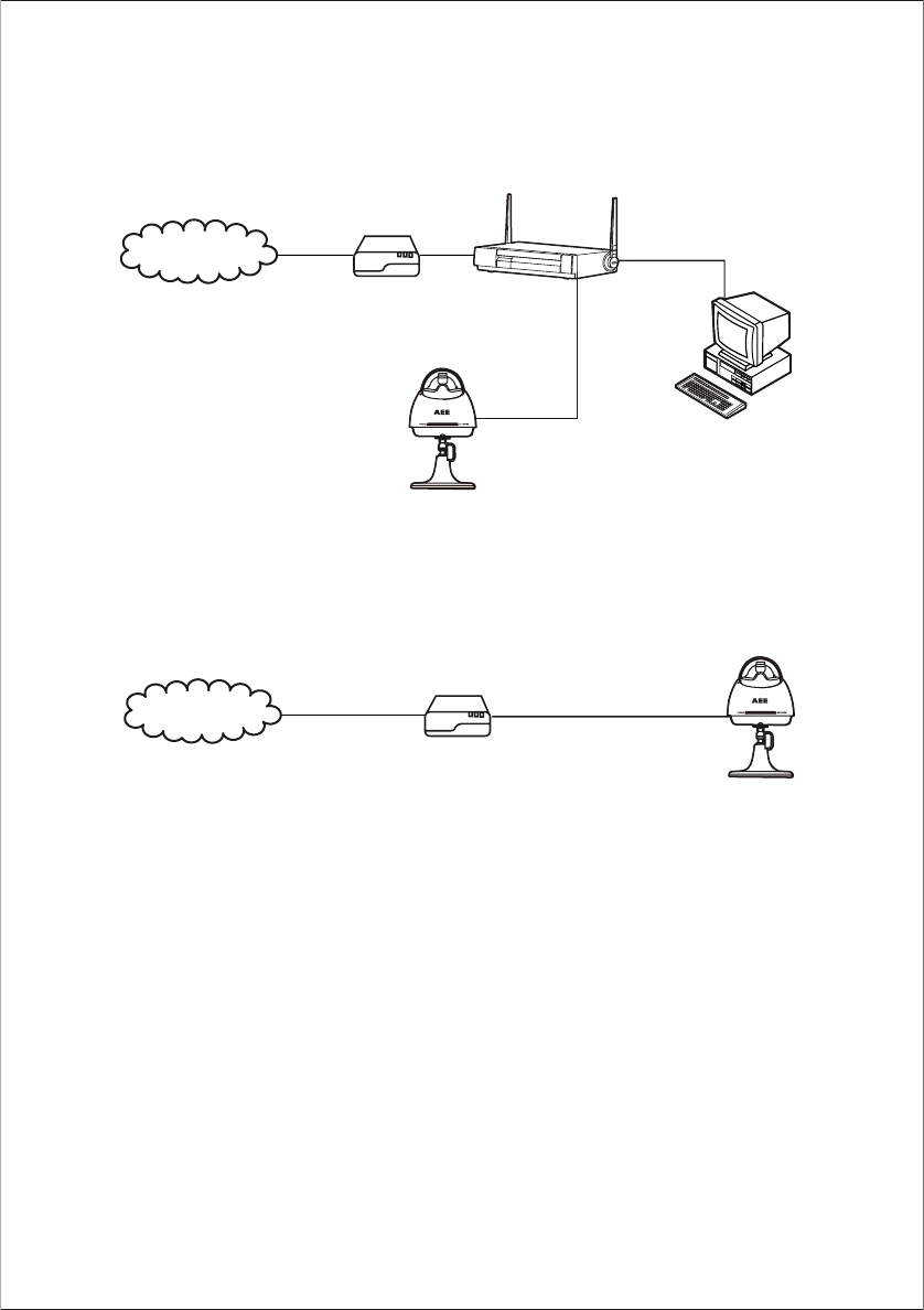
Type 2. Internet Connection with a Broadband Router
The NC601 can be accessed from the Internet. The broadband router needs Port Forwarding (IP
Masquerade) feature on page 23.
Internet
Modem WAN
CATV
XDSL
Optical Cable
Wireless
Router
LAN
Type 3. Internet Direct Connection with a Modem
The NC601 can be installed with a Modem directly on the network.
12
Internet
Modem
IP Finder Installation
13
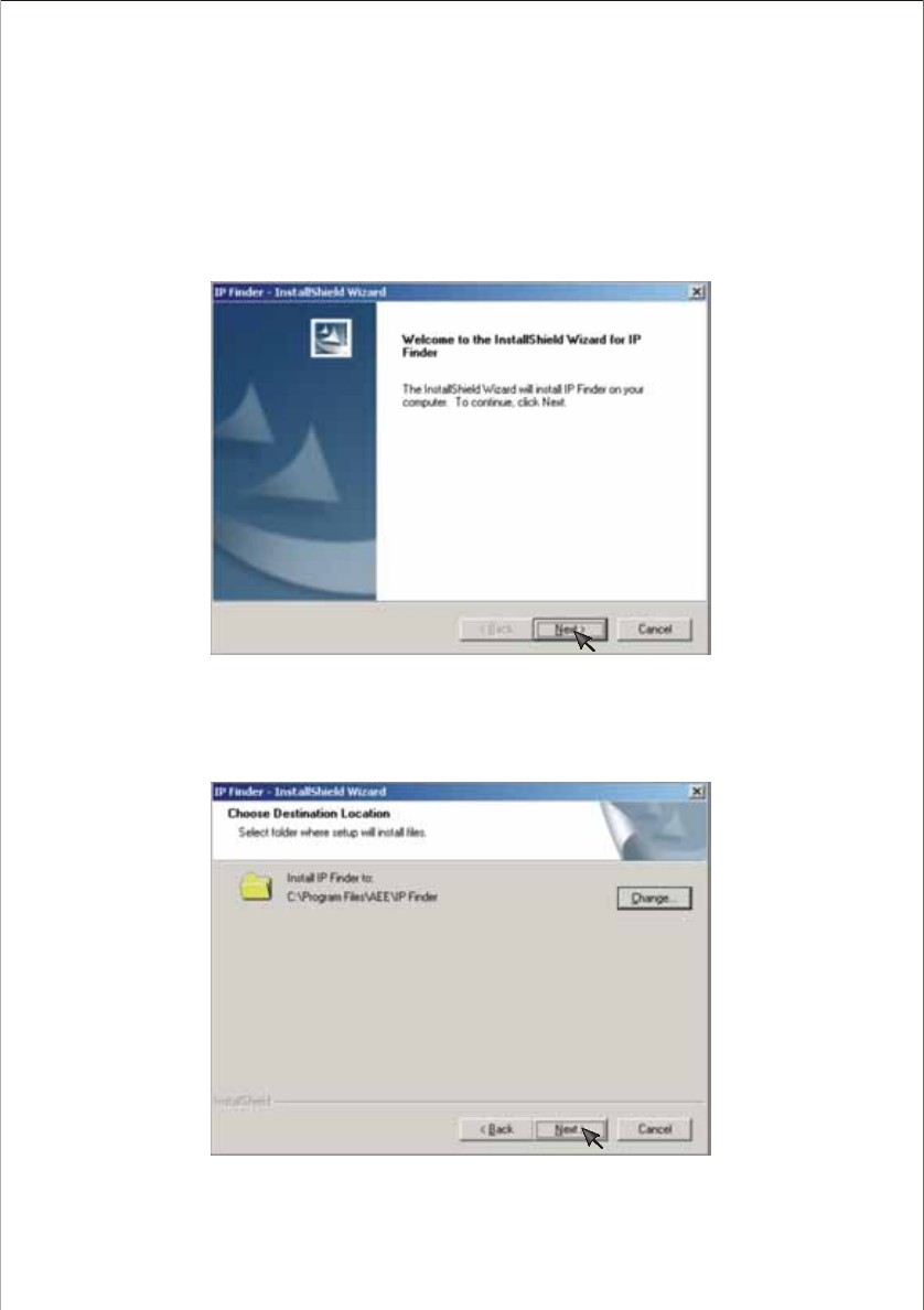
2.Select folder where setup will installation. If you want to change the default path. Press Change... to
replace the path.
Insert the Setup CD-ROM in the CD-ROM drive of the PC. This will start the installing wizard.
The IP Finder program can easily and quickly help your find NC601on the network.
1. Start your PC.
2. Insert the Setup CD-ROM in the CD-ROM drive of the PC. (If Network Camera Setup window does not
appear, click "setup.exe" on the Setup CD-ROM.)
14
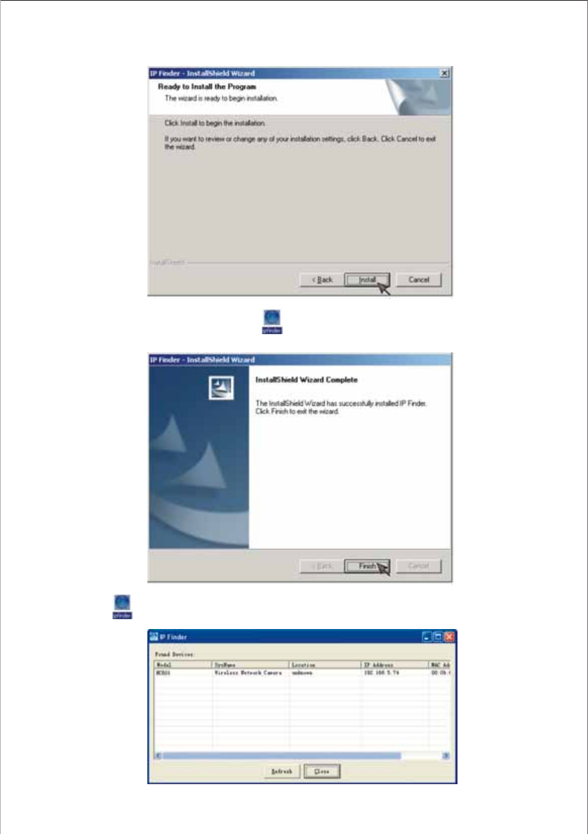
3. Click Install to install IP Finder.
5. Double-click to launch the program.
4. Click Finish to end up the installation. Icon will be created on the desktop.
Network Parameters
How to refer the network parameters from the PC
If you cannot get the network parameters, you can refer to the network parameters except for IP address
from the PC on the same network in the following procedure.
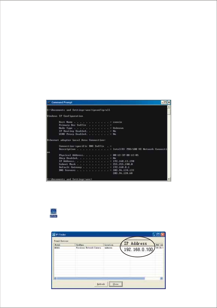
When using Windows 2000 or Windows XP
1. Click [Start] –> [Program] (–> [Accessories]) –> [MS-DOS® (Command) Prompt]. MS-DOS Prompt
window opens. These steps are slightly different depending on the operating system.
2. Enter "ipconfig /all" and press [Enter].
3. Enter "exit" and press [Enter] to close the window.
15
Use IP Finder to find IP address of your network camera
1. Connect your NC601 and PC with RJ-45 cable.
2. Double-click icon . The following window appears. IP address may differ according to different
network environment. Take the 192.168.0.100 as example:
Setting IP Address of the PC
1. Follow the steps below, appropriate for your operating system to open TCP/IP Properties window on the
PC.
Windows 2000
[Start] –> [Settings] –> [Control Panel] –> [Network and Dial-up Connections] –>
[Local Area Connection Icon] in use –> [Properties] –> Select Internet Protocol [TCP/IP] –>
[Properties] –> [Use the following IP address]
Windows XP
[Start] (–> [Settings]) –> [Control Panel] –> [Network and Internet Connections] –>
[Network Connections] –> [Local Area Connection Icon] in use –> [Properties] –> Select Internet
Protocol [TCP/IP] –> [Properties] –> [Use the following IP address]
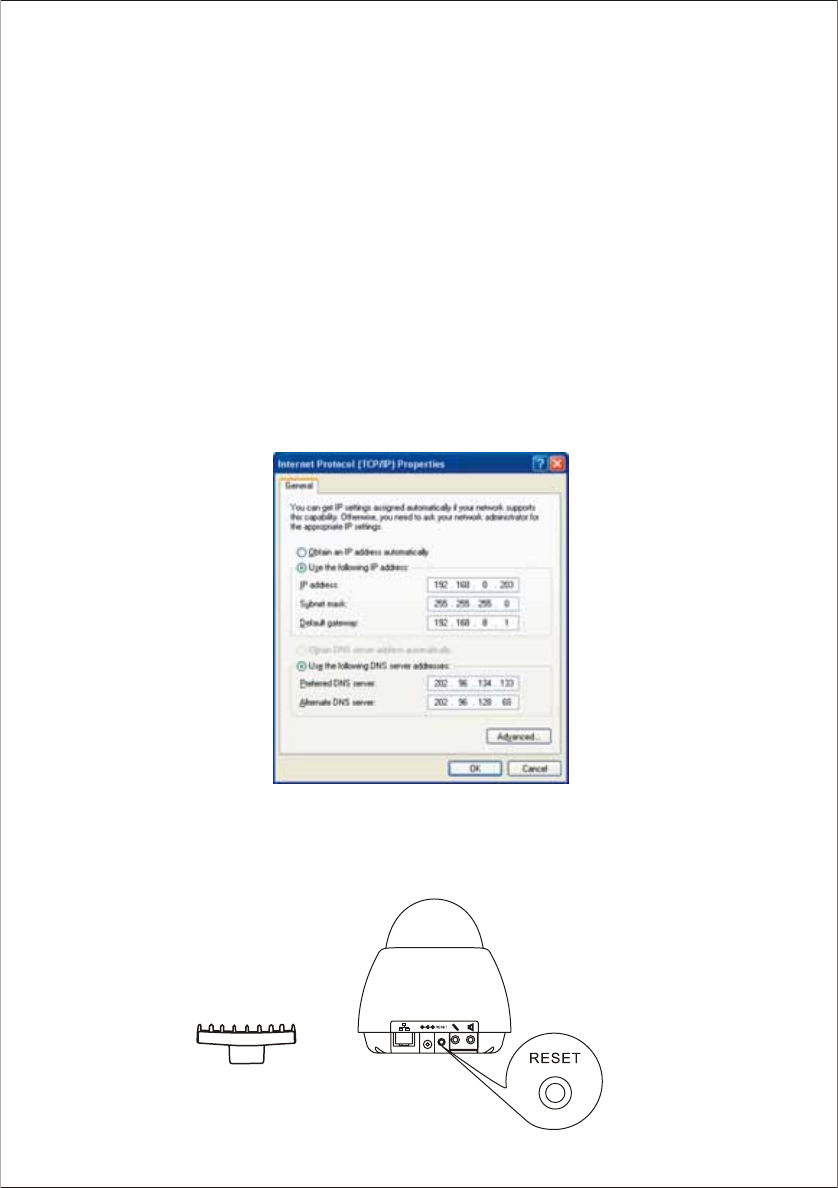
2. TCP IP Properties window appears. Set "192.168.0.X” in the IP address data field and "255.255.255.0"
in the Subnet Mask data field (X can be 0~255 except 100). This makes the camera and your PC in the
same net segment.
3. Click [OK].
Shield Cover
Note:
If you forget your settings, you can remove the shield cover, press the RESET button on the NC601 to enable the default
settings. You may refer to the Default Settings section on page 52~53 for more details.
16
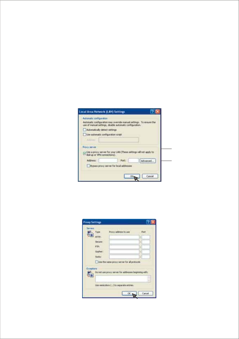
Proxy Server Setting
A proxy server may prevent you from connecting directly to NC601 in some corporate environments. The
web browser can set up the IP address communication without using a proxy server. Consult your ISP or
network administrator.
Note:
A proxy server is generally used to maintain security on a network that offers an Internet connection. The
network of NC601 with the proxy server may cause some problems to the image quality such as taking
much time in refresh interval. Consult your ISP or network administrator for details.
1. Start up the Internet Explorer.
2. Select [Tools] –> [Internet Options...] –> [Connections] tab and click [LAN Settings]. See if the Use
a proxy server check box is checked or not in the next window. When checked, click [Advanced...].
3. Enter the IP address of your NC601 assigned from your ISP or network administrator into the [Do not
use proxy server for addresses beginning with data] field.
4. Click [OK] on all of the opening windows.
17
See if the check box
is checked or not
When checked, click
[Advanced...]
When not checked, click [Cancel]. Your proxy server settings cause no problems.
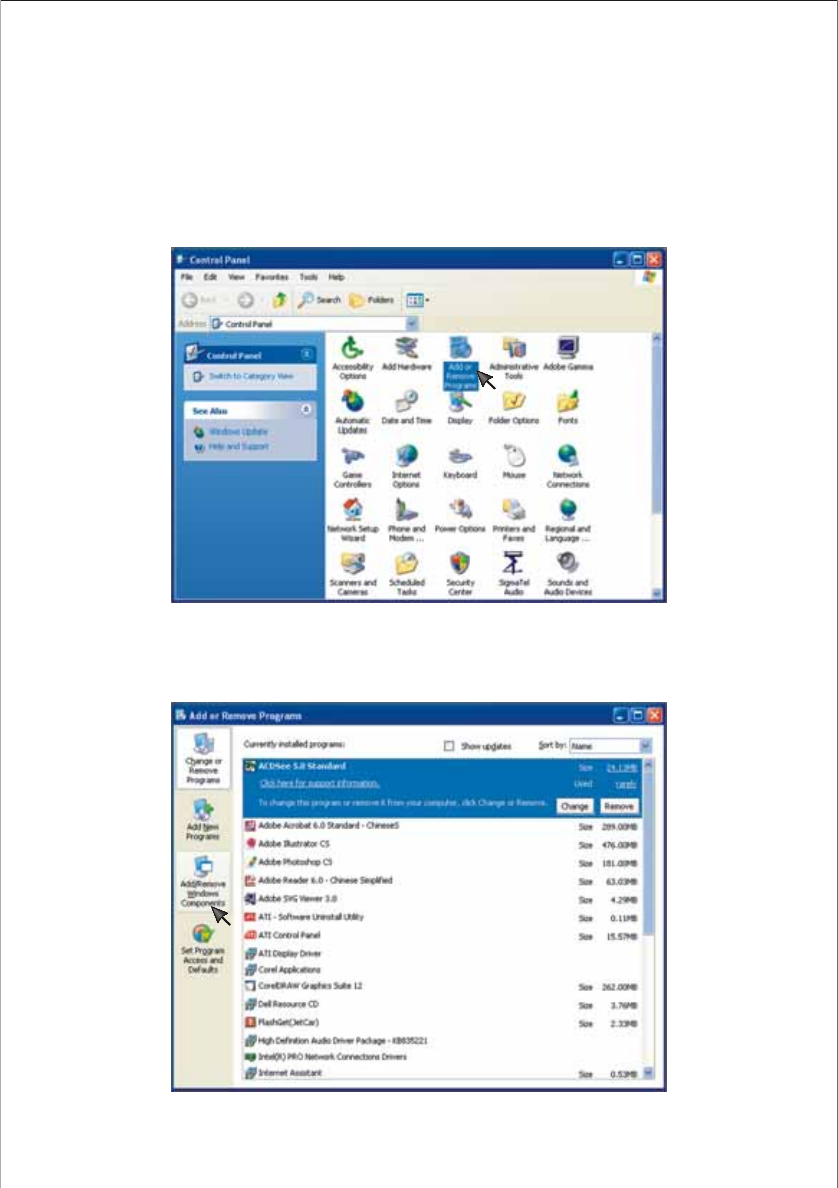
UPnP Function
UPnP means Universal Plug and Play. This function is only suitable for Windows XP. Please take the
following steps to activate this function.
1. Click [Start] (–> [Settings]) –> [Control Panel]–> [Add/Remove Programs]
2. Click [Add/Remove Windows Components].
18
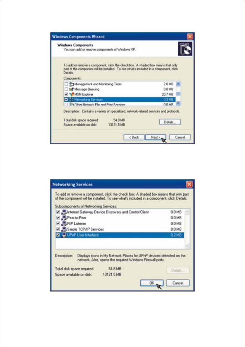
3. Double-click [Networking Services].
4. Activate the UPnP function.
19
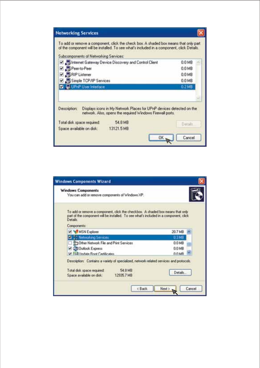
5. Click [OK].
6. Click [Next].
7. Click [Finish]. The UPnP function is enabled.
20
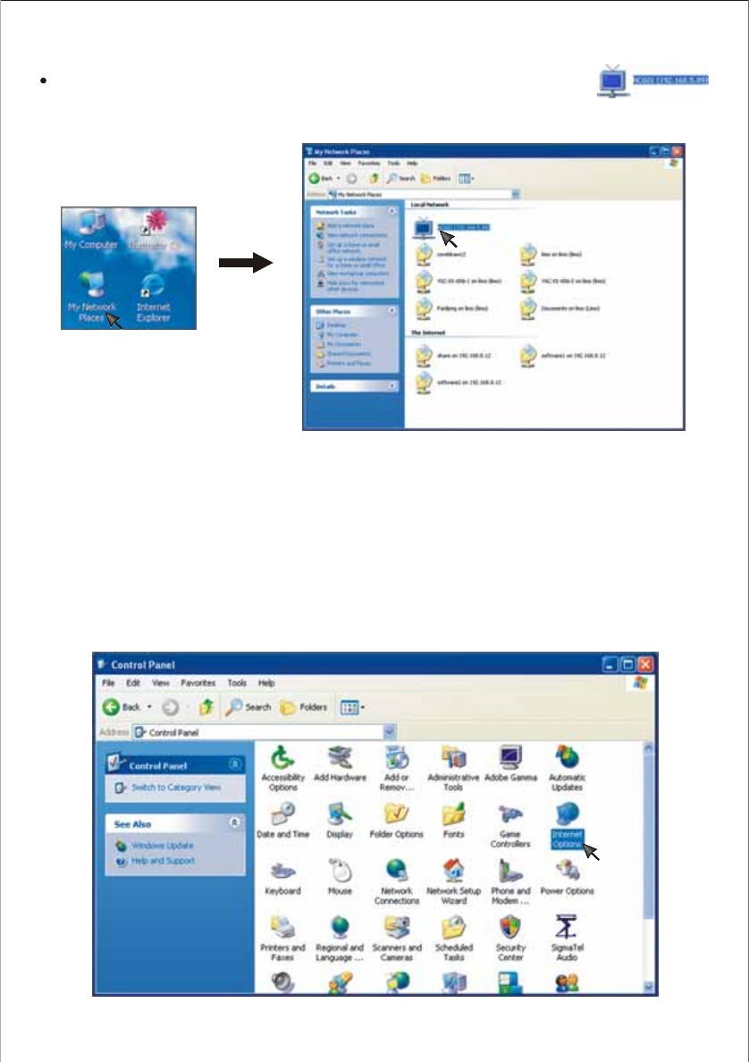
Notes:
After the UPnP function is enabled, click My Network Places, you will see the icon
the Network Camera is connected correctly.
21
Internet Explorer Security Settings
ActiveX will be used during reviewing the pictures from the NC601 via Internet Explorer. Please take the
following steps to reset the Internet Explorer safety.
1. Click [Start] (–> [Settings]) –> [Control Panel]–> [Internet Options].
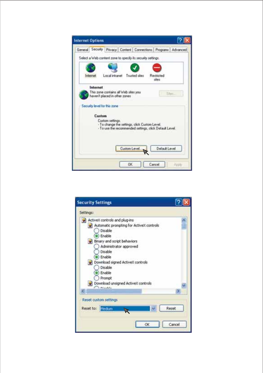
2. Click [Security]–> [Custom Level].
22
3. Set the security as the following, and reset the security to Medium, then click OK.
23
Notes:
Set “Automatic prompting for ActiveX controls” as Enable.
Set “Download signed ActiveX controls” as Enable.
Set “Download unsigned ActiveX controls” as Enable or Prompt. You are recommended to set
as Prompt.
Set “Initialize and script ActiveX controls not marked as safe” as Enable or Prompt. You are
recommended to set as Prompt.
Set “Run ActiveX controls and plug-ins” as Enable.
Set “Script ActiveX controls marked safe for scripting” as Enable.
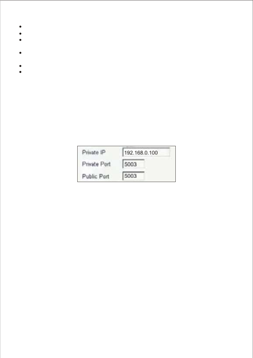
The firewall security features built into the router prevent users from accessing the video from the NC601
over the Internet. The router connects to the Internet over a series of numbered ports. The ports normally
used by the NC601 are blocked from access over the Internet. Therefore, these ports need to be made
accessible over the Internet. This is accomplished using the Virtual Server function on the router. The
Virtual Server ports used by the camera must be opened through the router for remote access to your
NC601. See below figure.
Private IP(IP address of NC601 ): 192.168.0.100,Private Port: 80, Public Port: 80.
Important: Some ISPs block access to port 80 and other commonly used Internet ports to conserve
bandwidth. Check with your ISP so that you can open the appropriate ports accordingly. If your ISP does
not pass traffic on port 80, you will need to change the port the camera uses from 80 to something else,
such as 800.
Viewing Your Camera
Not all routers are the same, so refer to your user manual for specific instructions on how to open ports.
After all the router settings have been entered correctly, a PC user inside or outside your network will
have access to the camera through the Internet Explorer Web browser.
To access the camera from the Internet, type the IP Address of the router given to you by your ISP,
followed by a colon, and the port number that you gave your camera (e.g., Http://202.115.122.96:800). It
is not necessary to enter the colon and port number if you are using the default Web server port 80. To
access from a computer on your local (home) network, simply enter the local IP Address of the Camera
(e.g., 192.168.0.100).
Set the Network Camera as Virtual Server
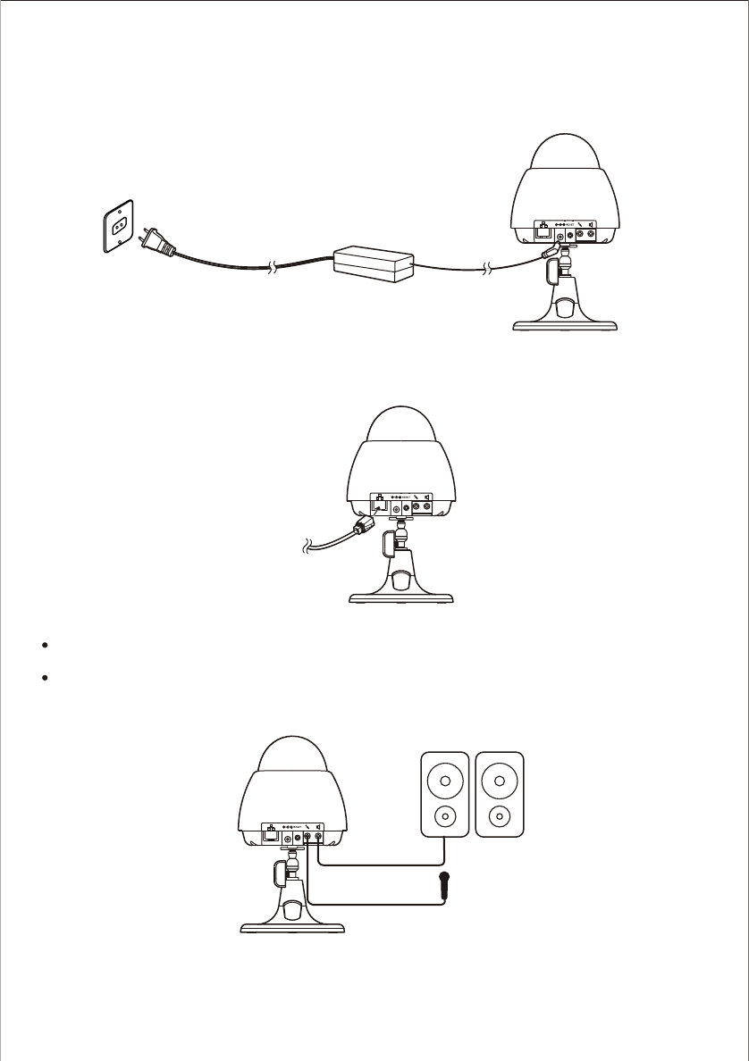
Power On the Network Camera
1. Remove the shield cover from the NC601. Connect the power adapter to the power jack of the NC601.
The power indicator will light up.
2. Connect the Network Cable to the cable jack.
Notes:
The Network LED will light up red when connected to Wireless Network, and will light up green when
connected to Wired Network.
You can connect the external Microphone or Speaker to your NC601 optionally.
Speaker
Microphone
24
NETWORK CAMERA SCREEN AND SETUP WINDOW
You can select one of the three ways to review the pictures from the NC601.
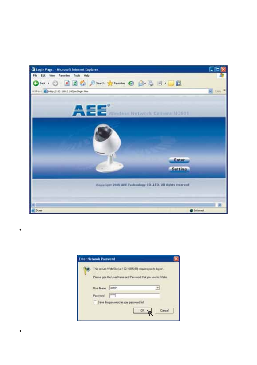
1. Input the IP address (or URL) of the NC601 on the Web Browser. Yo u will see the home page.
Click [Enter].
Notes:
Through this welcome page, you are allowed to enter the picture viewing interface or enter the
system setting interface. After inputting the correct username (the default is admin, in lowercase) and
password (the default is admin, in lowercase), you could choose to click on the item Enter to access
the picture viewing interface or the item Setting to access the system setting interface.
The general users assigned by the administrator are not allowed to enter the system setting interface.
They can only be allowed to enter the picture viewing interface.
25
Review images from the Network Camera
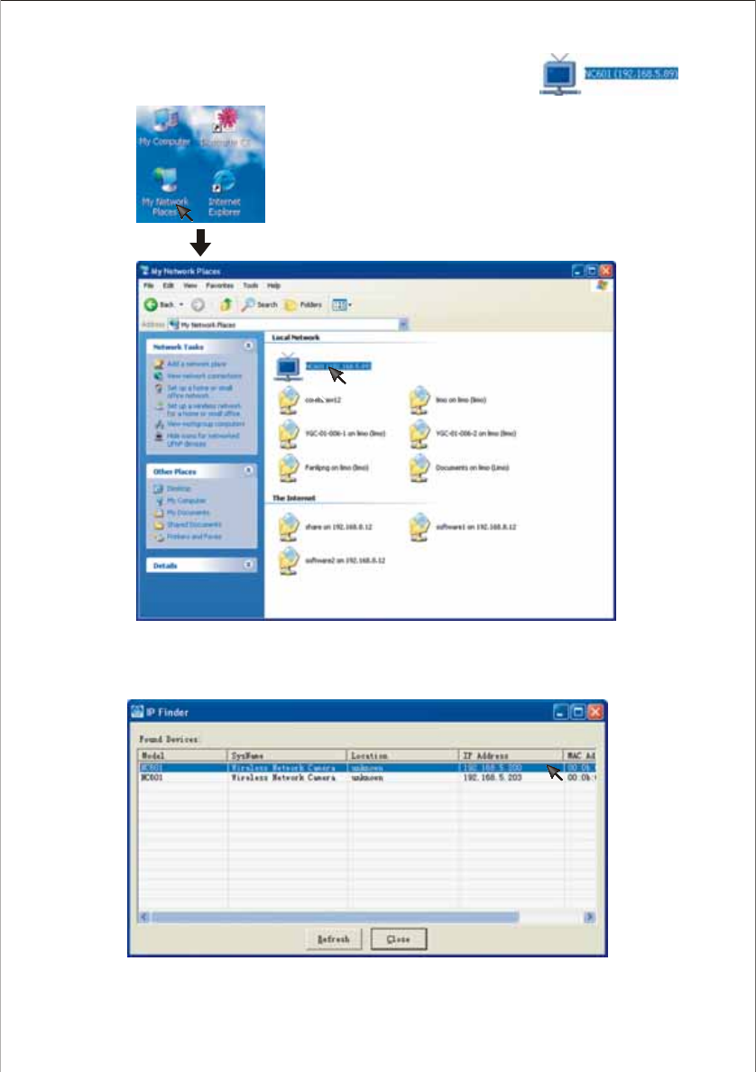
2. If your OS is Windows XP, click [My Network Places], double click the icon
You will see the home page, click [Enter].
26
Note:
If DHCP server is installed in your network, the IP address of your network camera may not be the default value
192.168.0.100. We recommend you use IP Finder to get the default IP address of your camera then.
3. Make sure the IP address of the NC601 the same net segment as that of the PC . Run the IP Finder
and double-click the related NC601 IP address.
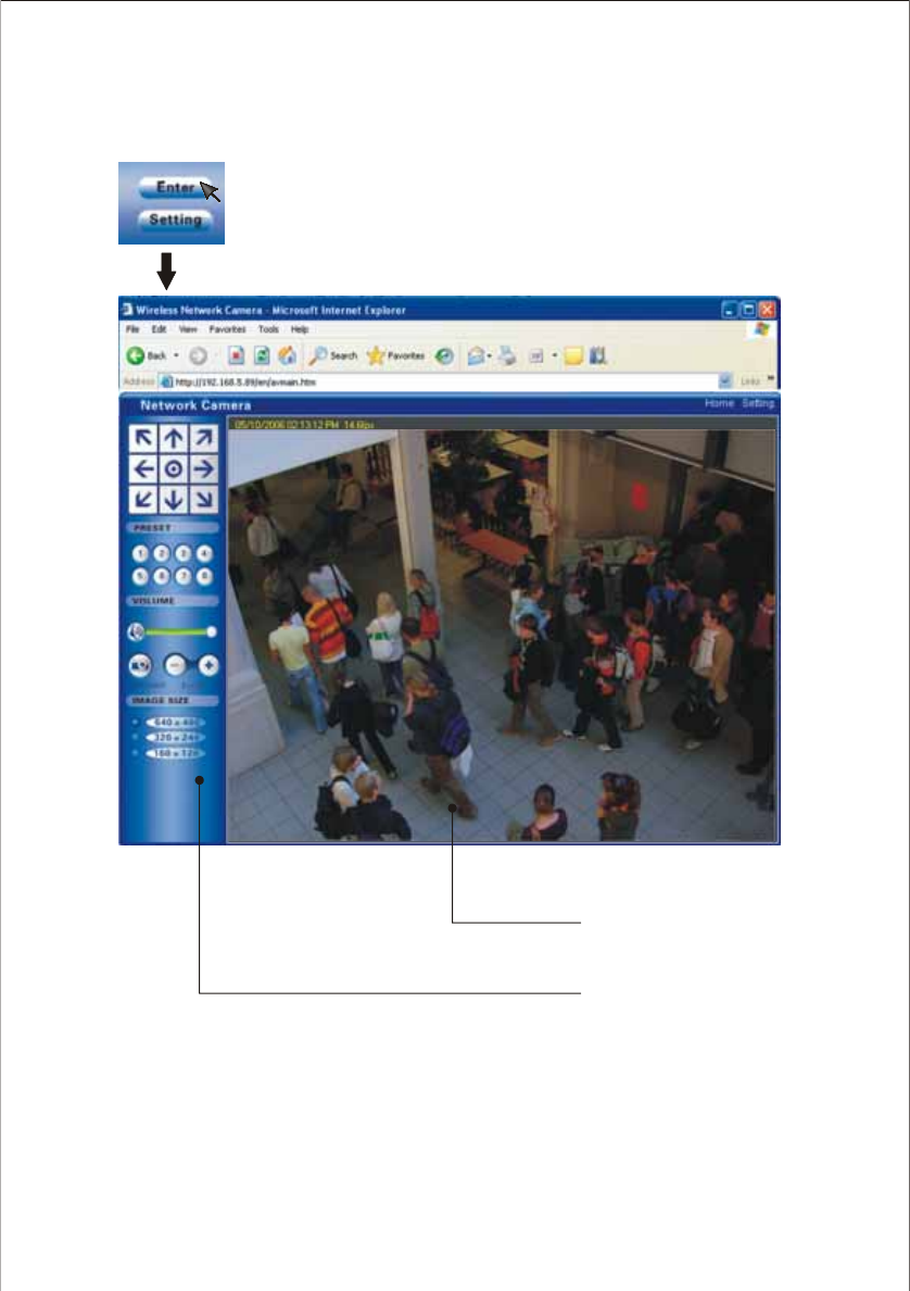
Operating Bar
Click Enter, you will see the screen.
Operation Bar
27
Image Field
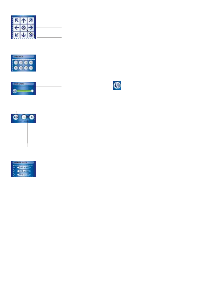
(1) Pan/Tilt button
Each surrounding arrow of Pan/Tilt moves the lens Up, Down, Right,
Left.
(2) Home position button
Moves the lens to Home Position.
(3) Preset Buttons
All eight preset buttons and home position button can be overridden.
Lens moves to the preset/ home position when clicking each registered
button. Blue/ White buttons mean Registered/ Not registered.
(4) Mute
4.1) Press Mute button to turn on/off the volume
4.2) Slide the slide block horizontally to adjust volume per your request
(5) Snapshot
Press the Snapshot button to obtain a snapshot of present detective
image.
Press Save to store it in your computer, and it will be automatically
named by present data & time
Press Cancel to exit.
(6) Zoom in
Press Zoom+ to magnify image area to see the details, and press
Zoom- to return the normal view
(7) Image size:
Three Image Size options for your request: [640x480], [320x240] and
[160x120].
(1) Pan/Tilt button
(2) Home position button
4.1)Mute button
(5) Snapshot button
4.2) Slide block
(6) Zoom in/out button
(7) Image resolution
(3) Preset button
28
Note: The Pan/Tilt function makes it possible that clicking on the Image Field will turn the lens to directions you like.
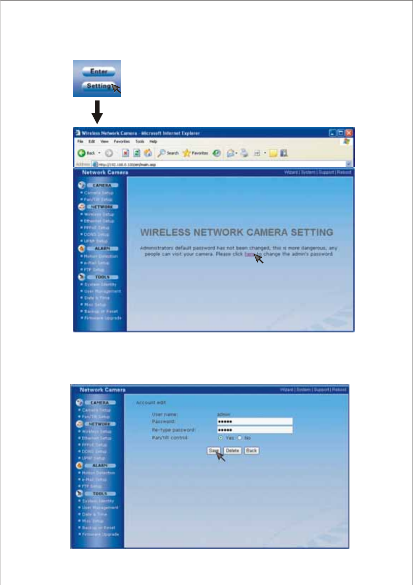
Network Camera Setting Interface
2. For the first time using or after resetting your NC601 to default settings, account edit interface will appear
as below. We recommend you click here to change the admin’s password and then Save for security.
By the way, admin (in lowercase) is the default setting, if the password is this, the above interface will
always appear when you enter.
29
1. Click setting, you will see the below interface.
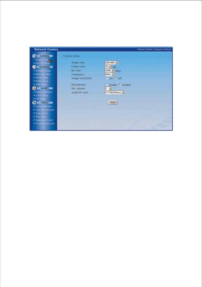
For camera setup, you can set Image size , Frame rate, Bit rate, Frequency and so on. You can also turn
the built-in Microphone on, adjust Mic volume and set the Audio bit rate.
[Image size] 640 x 480(VGA), 320 x 240(QVGA), 160 x 120(QQVGA)
[Frame rate] 10/15/20/25/30(fps) five options for your request.
[Bit rate] Five options for your request: 512, 768, 1024, 1536, 2048(kbps).
[Frequency] 50Hz & 60Hz for your request.
[Image revolution] Display images upside down.
[Microphone] Turn on/off the built-in microphone.
[Mic volume] Adjust the volume of the microphone, 0~15 options for your request.
[Audio bit rate] Audio clips transmission speed.
Click Apply to confirm your settings.
Note:
1. For Image size, smaller the image size, unclearer but smoother the picture.
2. For Bit rate, lower the bit rate, lower the image quality
3. For Frequency:
3.1) Generally speaking, 50Hz is often used in China, Australia and Europe, 60Hz used in the USA, Canada, Japan
and Korea. The frequency should match that of your country, otherwise, the interruption and interference occur.
3.2) For 50Hz, maximum admitted frame rate is 25fps, while 60Hz is 30fps.
Camera Setup
30
CAMERA
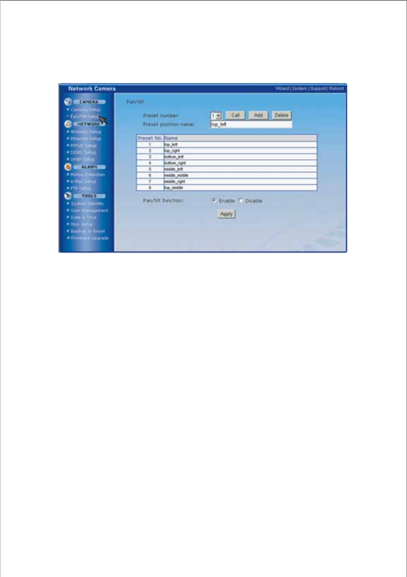
[Preset number] 1~8 up to 8 preset positions can be memoried.
Call: Turn the lens to the very position you select.
Add: Add new preset position(s)
Delete: Delete former preset position(s)
[Preset position name] Name for the preset position you set.
[Pan/ tilt function] Enable the lens circumvolution function or disable on the operation bar.
Click on Apply to confirm your setting to enable/disable Pan/Tilt function.
Pan/ Tilt setup
Pan/Tilt operation can move the lens 130° horizontally and 70° vertically. This movable lens extends your
visual angle. The registered Preset Position can be demonstrated on the Operation bar(Refer to page 27).
31
NETWORK
Wireless setup
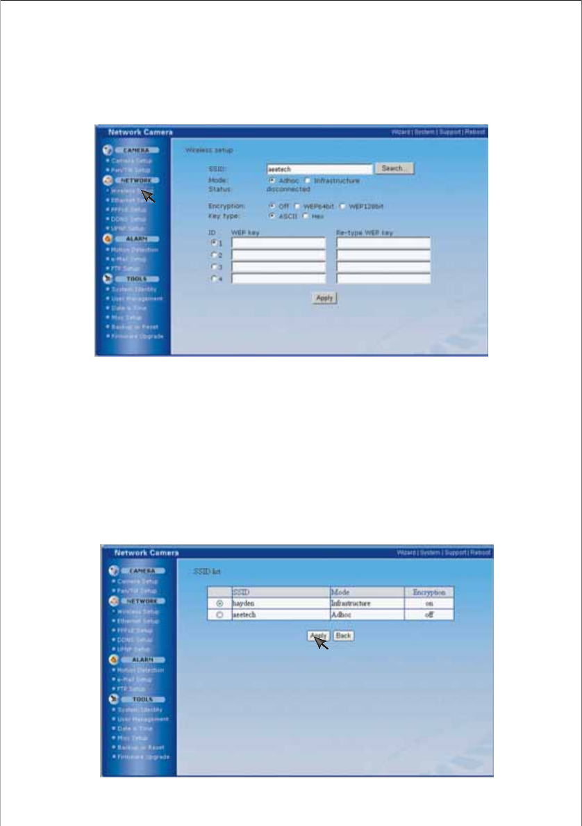
The NC601 corresponds to the wireless system based on IEEE802.11b/g. Encryption establishes the
security to prevent unauthorized users to access the wireless data communication.
[SSID] Type the ID to identify the wireless network you want to access using up to 32 ASC characters.
For your security, be sure to change the factory setting.
[Mode] Infrastructure mode and Adhoc mode
Select Adhoc mode when connecting to computer directly,
elect Infrastructure mode when connecting to computer via an access point or a radio router.
[Status] Show the status of the wireless connection.
[Encryption] Select the key length, either 64 or 128 bits.
[Key type] You can type the WEP key either in hexadecimal numbers or ASC characters.
[WEP key] Specify up to 4 WEP keys.
Note:
You can use the present SSID or you can click Search... to search new SSID. And then click Apply to use it, or Back to
cancel it.
Ⅱ
Adhoc Mode:
Infrastructure Mode: S
Ⅱ
32
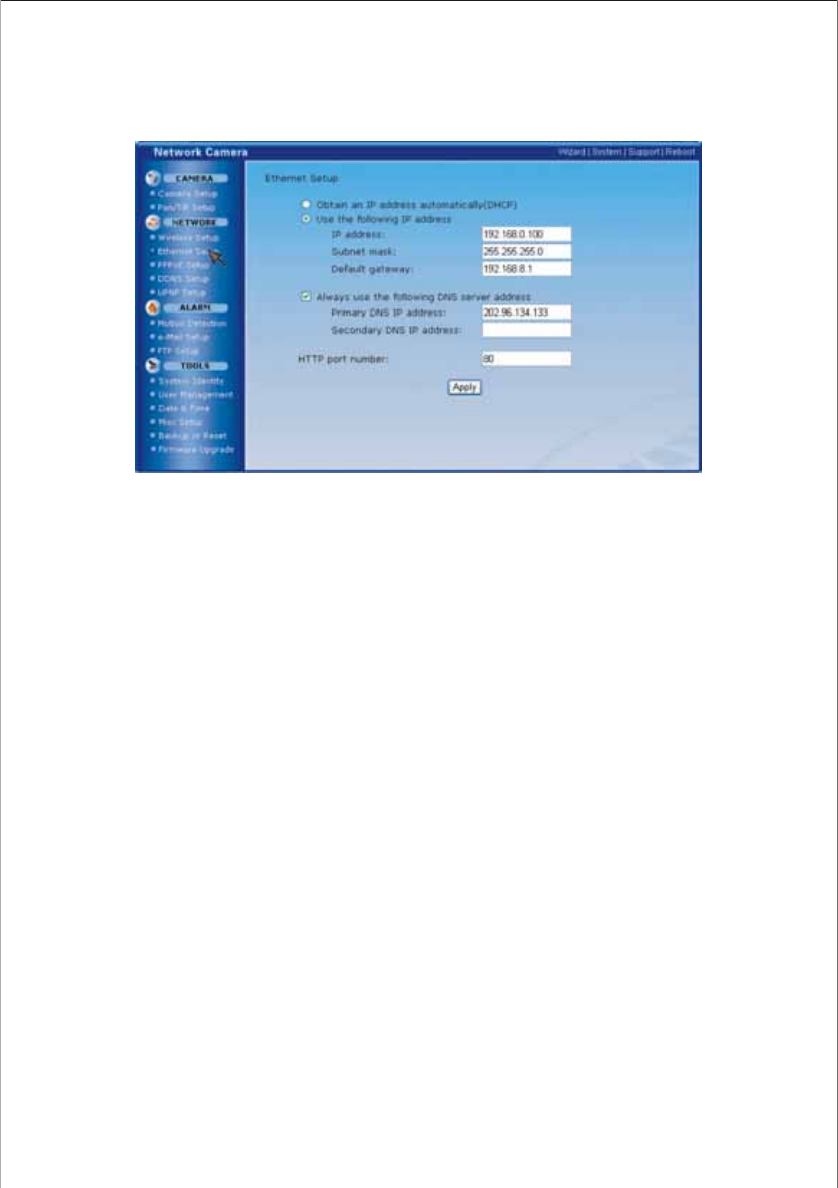
Ethernet setup
Obtain an IP address automatically(DHCP):
If DHCP server is installed on the network, select it when the IP address is assigned by DHCP server. IP
address is assigned automatically.
Note:
If DHCP server is installed on your network, the interface may differ from the above image after clicking on Ethernet
setup.
Use the following IP address:
Select this when a fixed IP is set.
[IP address] Type the IP address of your camera
[Subnet mask] Type the subnet mask
[Default gateway] Type the default gateway
Always use the following DNS server address:
[Primary DNS IP address] Type the IP address of the primary DNS server
[Secondary DNS IP address] Type the IP address of the secondary DNS server, if necessary
HTTP port number
The default HTTP port number is 80.
33
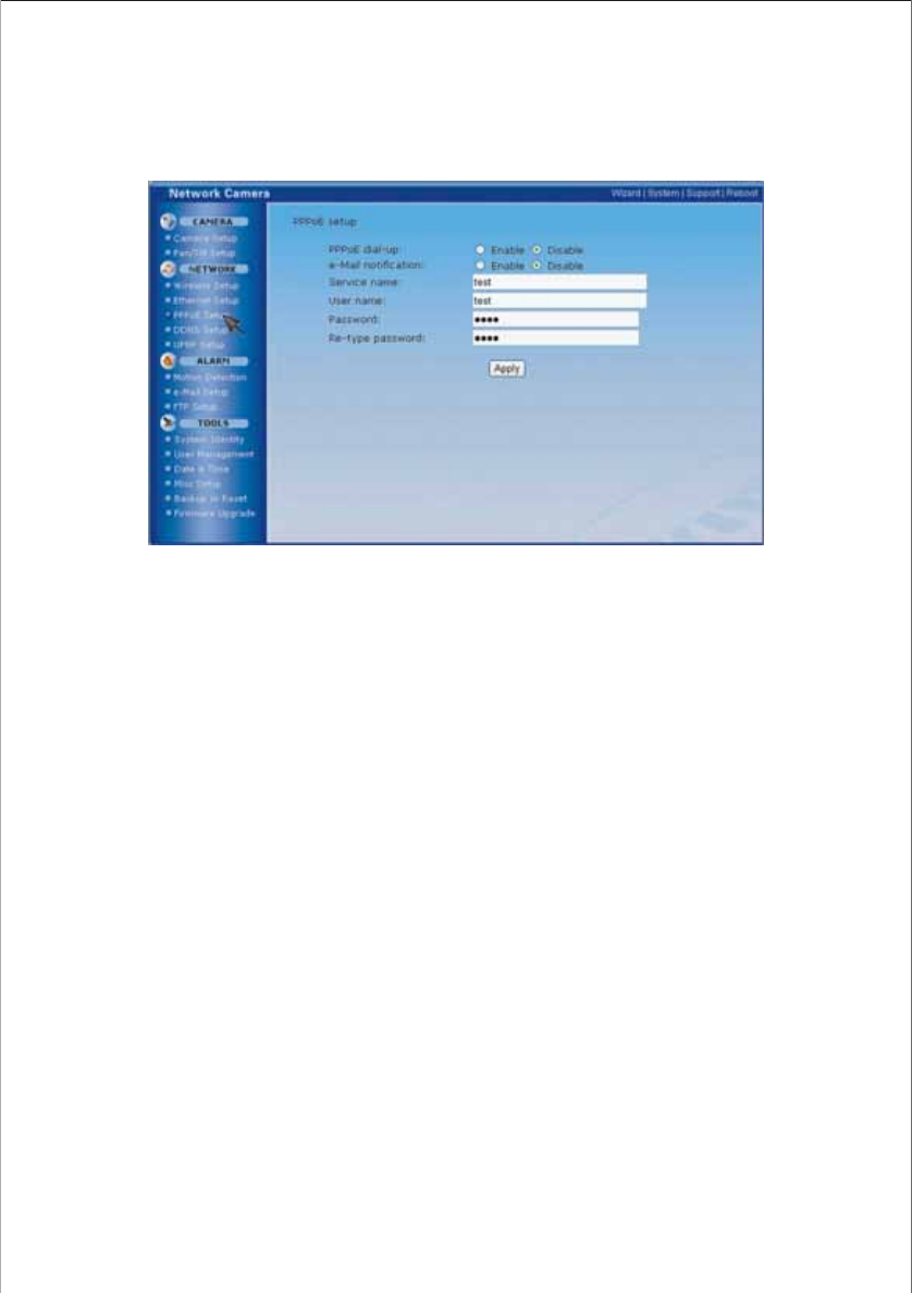
PPPoE setup
The NC601 can be installed alone without PC on the network. Some XDSL services use PPPoE (Point-to-
Point Protocol over Ethernet ).
[PPPoE dial-up] Enable or disable PPPoE connection
[e-Mail notification] Remind you with IP address of your NC601 if Enable selected. The precondition is
that you have set the relative parameters in your e-mail set (Refer to page 40 for E-mail alarm setup).
[Service name] Either an ISP name or a class of service that is configured on the PPPoE server.
[User name] Type a user name.
[Password] Type a password.
[Re-type password] To confirm the password, type the same characters as you typed in the Password
box.
Click on Apply to confirm your settings.
34
How to access via PPPoE connection
1. After the , reboot your network camera.
2. Connect the camera to internet. Refer to Wired Network-Type 3. Internet Direct Connection with a
Modem on the network on Page 12.
Thus you can access your camera via DDNS or IP address reminded by e-mail.
setup
35
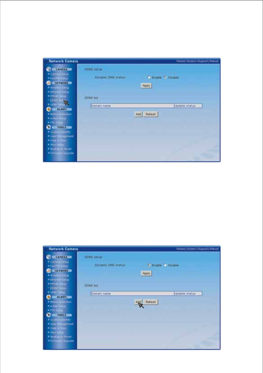
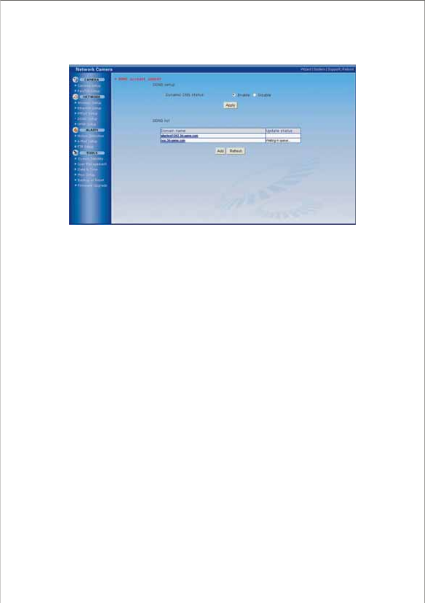
DDNS setup
Verify that your ISP supports DHCP. If your ISP supports DHCP, or if you assign a domain name to the
NC601, you need to contract and register for DDNS service. If you set static global IP address to the
NC601 and the broadband router, you do not need to register DDNS service.
[Dynamic DNS status] Enable or disable DDNS connection
Click Apply to confirm [Dynamic DNS status] setting (enable/disable)
[DDNS list] Show the added dynamic domain name
Click Add to add new dynamic domain name(s)
Click Refresh to Refresh DDNS status
How to add DDNS
1. Firstly Enable the Dynamic DNS function and then click Add.
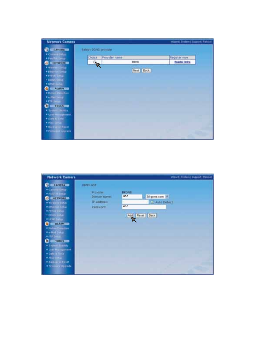
2. Click in the round below Choice and then click on Register Online to register a domain name and
obtain a password. Click Next (e.g., Domain name: ooo & Password: aee).
3. Fill in the blanks with domain name and password you obtain at Step 2, leave the IP address unfilled.
After that, click Add to finish the setup.
Note:
Click on Reset to set the device with another domain name, or Back to return the register interface.)
36
4. After the DDNS account added! appears on the setup interface. Yo u can use the domain name to
access your NC601 quickly and conveniently.
37
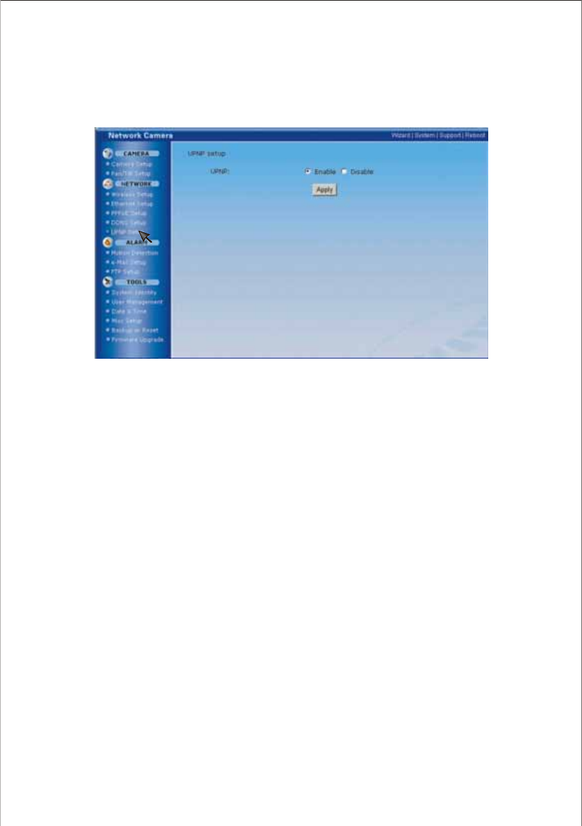
UPNP setup
UPnP function requires a Windows XP operating system. It is a quick way to find Network Camera in your
network.
Firstly you need to active the UPNP function on your PC, please refer to page 18-21 for more details.
[UPNP] Enable or disable the UPNP function.
Press Apply to enable or disable this function.
38
ALARM
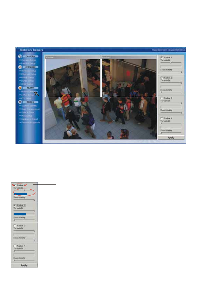
Motion Detection
As the alarm/timer trigger, Motion Detection can activate the Image Transfer feature, which can send the
images via e-mail or FTP (File Transfer Protocol). The alarm/timer trigger can be set on this window.
[Window] Up to four windows for you to detect and alarm.
[Threshold] Setup the threshold, once exceed the limit, alarm will be triggered.
[Sensitivity] Set the measurable difference between two sequential images that would indicate motion.
Note:
1. When remove a window (for example, Window 1, to another place, please press Apply to
make the new detective area in effect) .
2. Only the checked window area is effectively set for alarm.
3. It is easier to trigger the alarm that you slide the slide block of to left and that of
the sensitivity to right.
threshold
The checked window is effectively set as an alarm trigger.
External Sensor Input of External I/O activates the alarm trigger
39
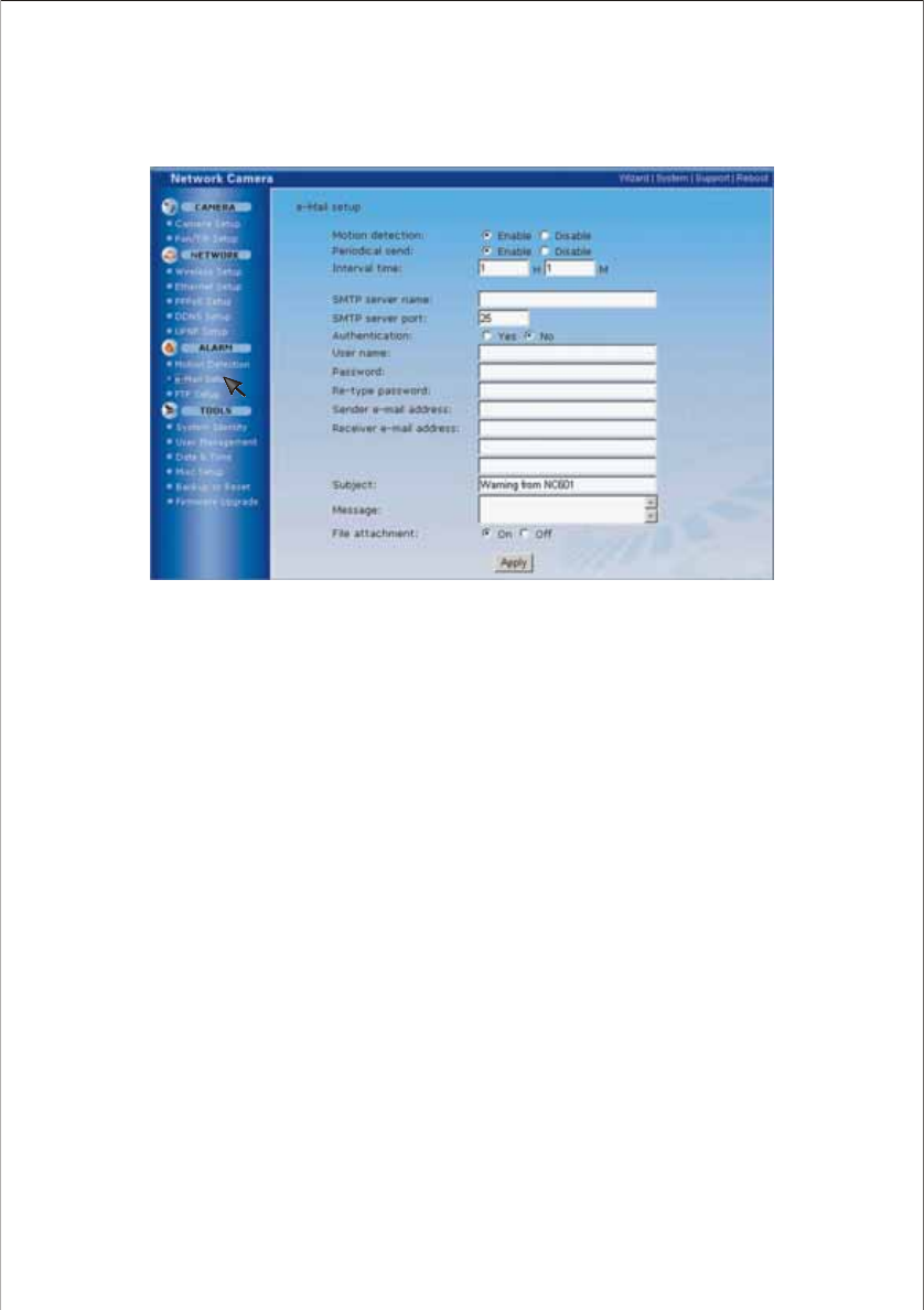
E-mail Alarm setup
NC601 can transfer the image via E-mail. The alarm/timer trigger can be set on Motion Detection
window.
[Motion detection] Trigger to the alarm
[Periodical send] Trigger to the alarm
[Interval time] Sending image frequency when enable the Periodical send trigger
[SMTP server name] Type the name or IP address of the SMTP server you want to use for sending an e-
mail
[SMTP server port] The default value is 25
[Authentication] Select the authentication required when you send an e-mail.
[User name] & [Password] Type the user name and password of the user who has the mail account.
This setting is necessary when the SMTP server which sends e-mail performs authentication
[Re-type password] Re-type the password above to confirm
[Sender e-mail address] Set the e-mail address by which you want to send e-mail
[Receiver e-mail address] Set the e-mail address by which you want to receive e-mail(Up to 3 receivers'
e-mail address can be set)
[Subject] Subject of the alarm e-mail
[Message] Description of the e-mail
[File attachment] Attach images shot by network camera or not (On/Off).
Note:
The Alarm mode , which uses the Network Camera internal clock., can send the e-mail without transferring the image.
Make sure Date and Time has been configured.
40
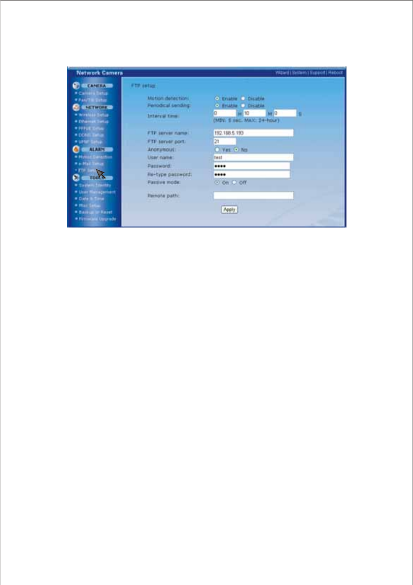
FTP Alarm setup
NC601 can also transfer the image via FTP. The alarm/timer trigger can be set on Motion
Detection window.
[Motion detection] Trigger to the alarm
[Periodical send] Trigger to the alarm
[Interval time] Sending image frequency when the trigger is Periodical send
[FTP server name] It can be domain name or IP address
[FTP server port] The default port number is 21
[Anonymous] Enable or disable anonymous visiting
[User name] Type your user name
[Password] Type your password
[Re-type password] Re-type your password
[Passive mode] Apply passive mode or not
[Remote path] Path to FTP server where to save the alarm images
Click on Apply to confirm your settings above.
41
TOOLS
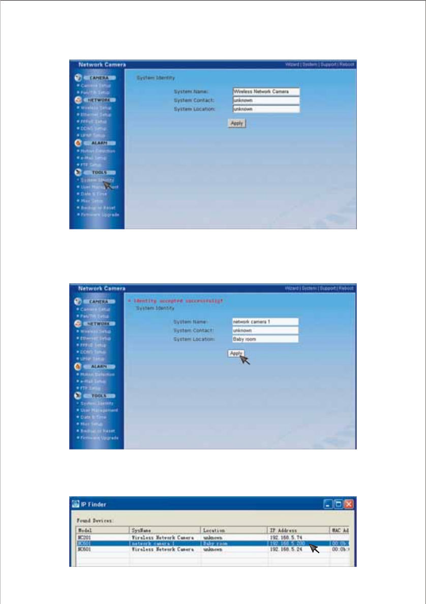
System Identity
[System Name] Name for the present NC601, to distinguish from other camera(s) in the network
[System Contact] Note the connecting data of the NC601
[System Location] Note the NC601 location
42
TIP:
These information you fill in can be displayed on and very important to the IP Finder. It can help to distinguish different
Network Cameras in the network. See the below figure.
43
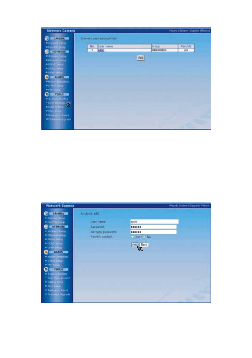
User Mana gement
[Add] Up to 64 users (including the admin) can be set
[Pan/tilt] Indicate whether or not users can use the Pan/tilt function
Note:
1. Maximum to 10 users are allowed to access the camera simultaneously.
2. As the number of users simultaneously connected to Network Camera increases, the overall motion performance
will decrease.
How to add users
1. Click Add.
2. Type a user name and password. Re-type the password to confirm your password. Select Yes or No for
the Pan/Tilt control. Then click on Add. One user has been added.
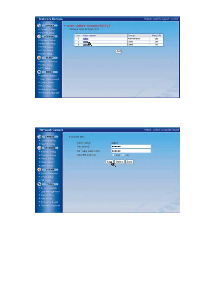
3. Click on one username, the following window will appear. You can change the password and enable or
disable user to use the Pan/Tilt control. Click Save to confirm your settings or Delete to delete this user.
44
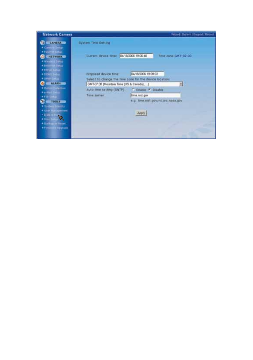
[Current device time] Internal time for NC601
[Proposed device time] External time for NC601 (time of client server PC)
[Select to change the time zone for the device location] choose proper time zone
[Auto time setting(SNTP)] Enable or disable this function
[Time server] Type one NTP server name in the box
Note:
1. If this NTP server cannot work in gear, the NC601 will be synchro with the clients’ PC.
2. With built-in RTC(Real-time Clock) , this device keeps track of the time even when the power supply is cut off.
Date & Time
45
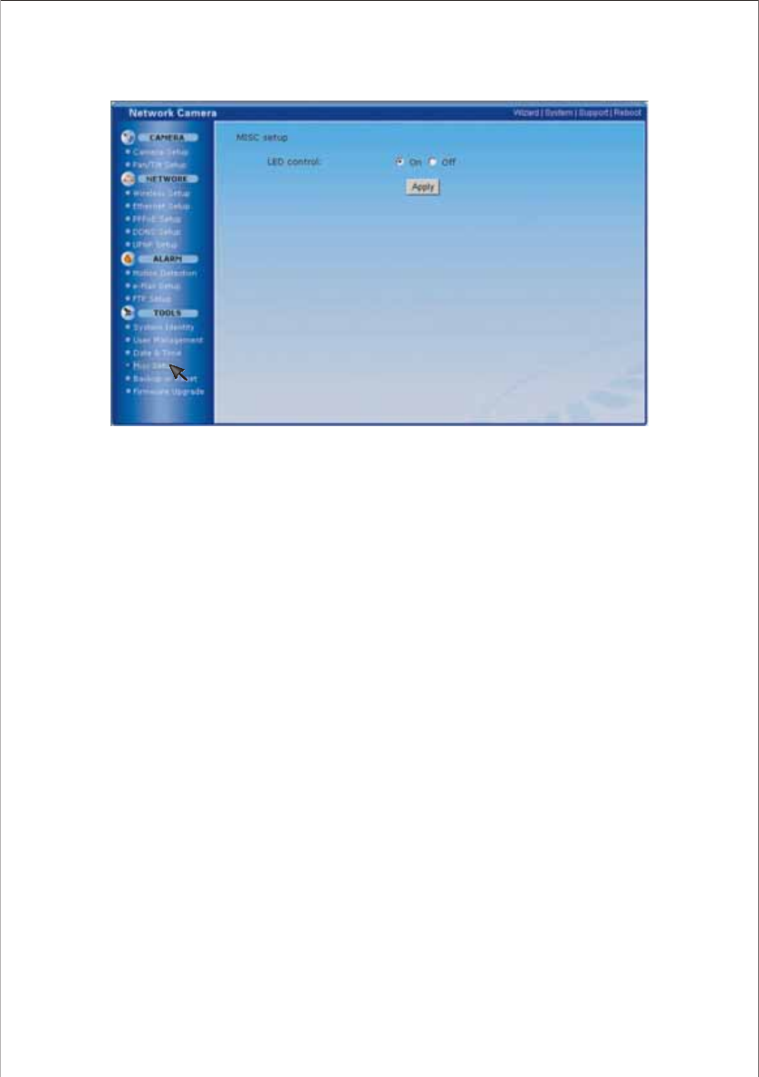
MISC setup
46
[LED control] Turn on/off the power & network LED indicator of NC601
Click Apply to confirm your above setting.
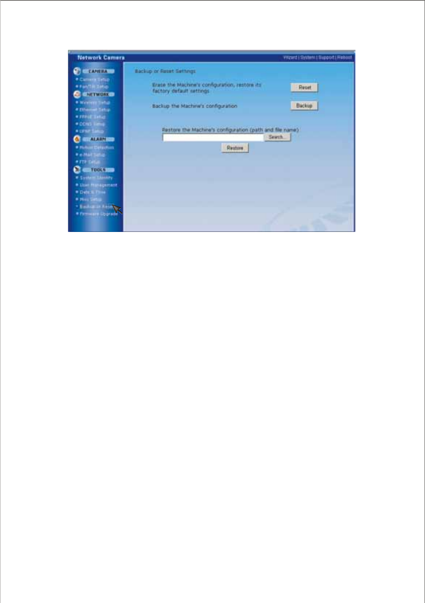
Backup or Reset
Note:
1. Do not turn off the power during the Reset to Factory Default. It may interrupt the NC601 operation.
2. If Reset to Factory Default is used, all user settings will be lost, and you will have to reconfigure the entire camera.
47
[Reset] Initialize all the parameters to the factory default. Note that all customer-applied settings will be
lost, requiring you to reconfigure Network Camera.
[Backup] Backup the present configuration for future reference.
[Search...] Search for the very backup configuration and click Restore to restore the configuration to your
Network Camera.
[Restore] Click Restore button to start restoring a former backup settings
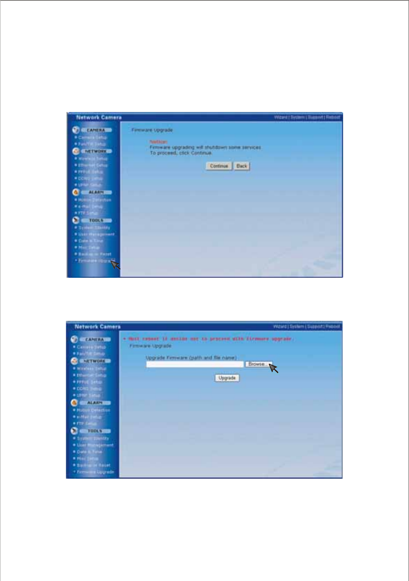
2. Click Browse... to search for the newest Firmware you downloaded. And then click Upgrade.
48
Firmware Upgrade
Upgrade the program to operate Network Camera on the latest version of the system. If new firmware is
released, you can download the latest program from Network Camera Technical Support Site. Installation
is easy and fast.
Check the latest firmware version on System Information Page on page 50.
1. Click Continue.
IMPORTANT:
* It is important to reboot your NC601 if you want to cancel the upgrade. Otherwise some
functions may be unavailable.
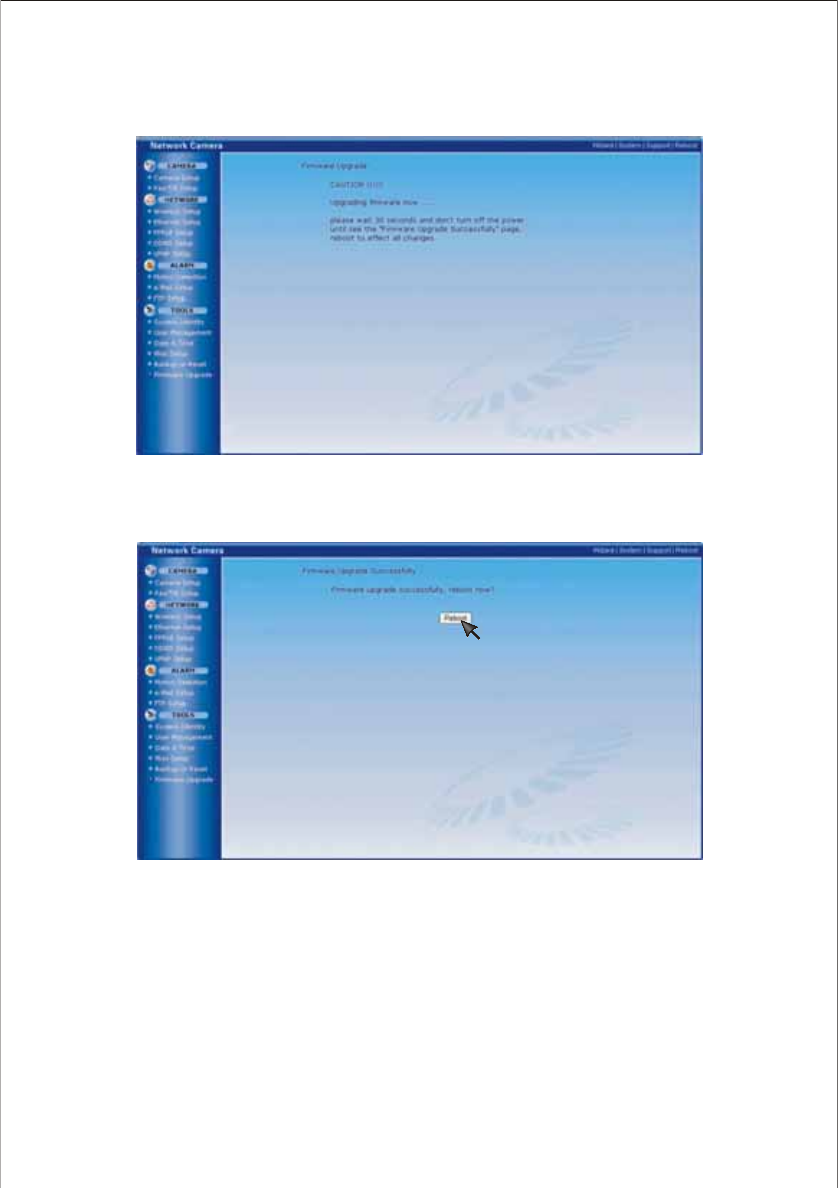
* Do not turn off the power during the Reset to Factory Default. It may interrupt the NC601
operation.
49
3. Click Reboot to update your camera.
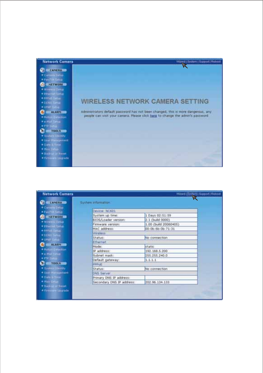
1. After pressing setting on the top interface, you will enter the below interface. Yo u can click Wizard to
do the quick parameter setting. Following the directions until you finish it.
2. Click System to see over system information about your camera
SPEEDREAD YOUR NETWORK CAMERA
50
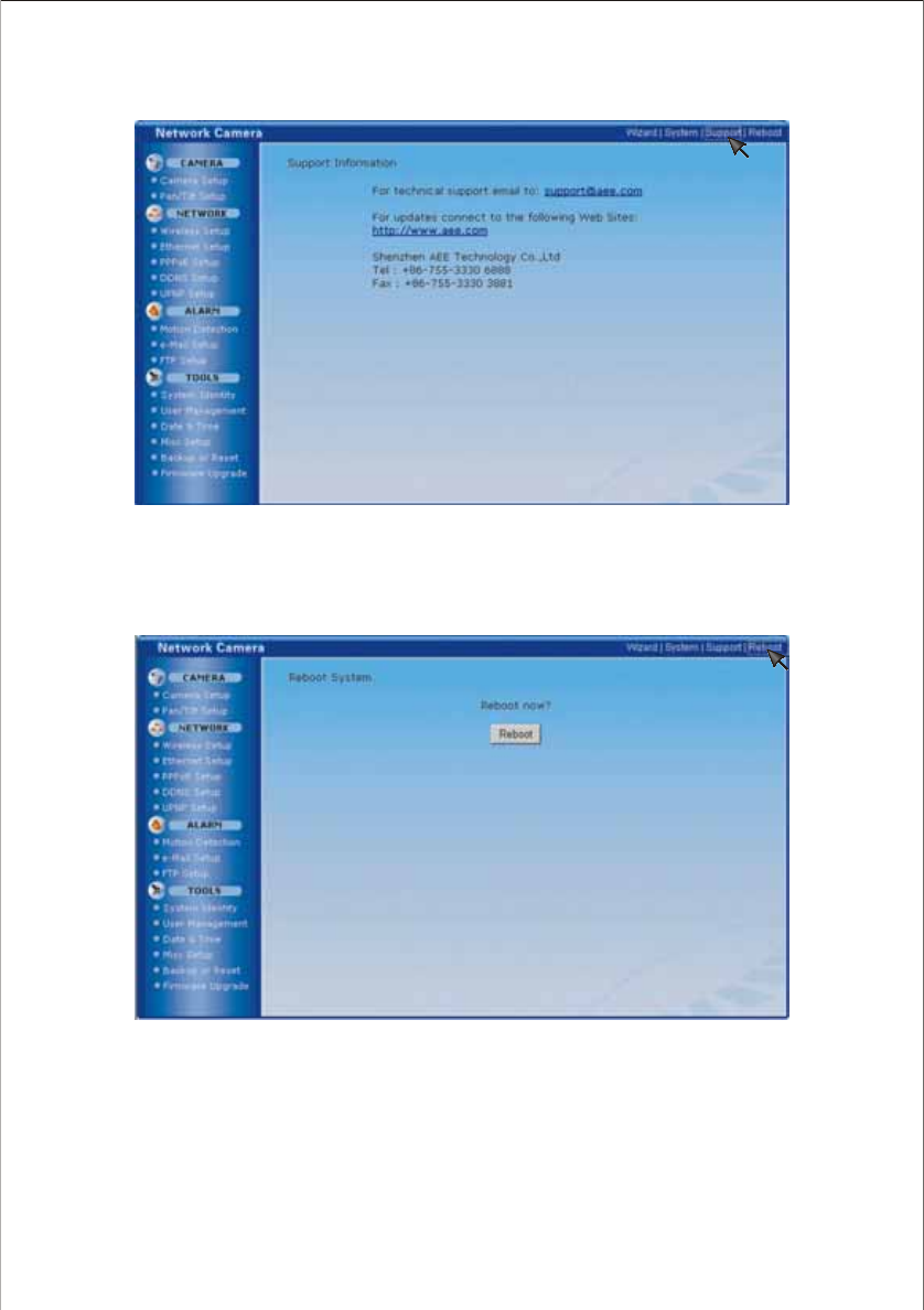
3. Click Support to see the support information
4. Click Reboot to restart the NC601.
Reboot NC601 retaining any settings you entered. If any operational issues are changed, try this option
first.
Note:
We recommend you rebooting your NC601 after you change PPPoE parameter. Otherwise some functions may be
unavailable.
51

IP address
Subnet Mask
Default Gateway
Primary DNS IP Address
Secondary DNS IP Address
HTTP Port Number
PPPoE Setup
PPPoE Dial-up
Service Name
User Name
Password
Re-type Password
DDNS Setup
Dynamic DNS Status
DDNS list
192.168.0.100
255.255.255.0
192.168.5.1
192.168.5.1
Blank
80
Disable
Blank
Blank
Blank
Blank
Disable
Blank
DEFAULT SETTINGS
Image Size
Frame Rate
Bit Rate
Frequency
Auto White Balance
Auto Gain Control
Image Revolution
Microphone
Mic Volume
Audio Bit Rate
Pan/Tilt Setup
Preset Number
Preset Position Name
Pan/Tile Function
320 x 240
30
2048kbps
60Hz
On
On
Off
Enable
10
G. 726 (40kbps)
1
Blank
Enable
Camera Setup
Mode
SSID
Encryption
Key Type
ID
WEP Key
Ad-hoc
aeetech
Off
Hex
1
Blank
Wireless Setup
Ethernet Setup
52

UPnP Setup
UPnP
Motion Detection
Window 1
Window 2
Window 3
Window 4
E-Mail Setup
Motion Detection
Periodical Send
Interval Time
SMTP Server Name
SMTP Server Port
Authentication
User Name
Password
Re-type Password
Sender E-Mail Address
Subject
Message
File Attachment
FTP Setup
Motion Detection
Periodical Sending
Interval Time
FTP Server Name
FTP Server Port
Anonymous
User Name
Password
Re-type Password
Passive Mode
Remote Path
Image File Name
Suffix
System Identity
System Name
System Contact
System Location
User Management
1
2
3
Date & Time
Current Device Time
Time Zone
Proposed Device Time
Auto Time Setting (SNTP)
Time Server
Misc Setup
LED Control
Enable
Blank
Blank
Blank
Blank
Disable
Disable
1h. 1m.
Blank
25
No
Blank
Blank
Blank
Blank
Warning from NC601
Blank
On
Disable
Disable
1h. 1m. 10s
Blank
Blank
No
Blank
Blank
Blank
On
Blank
test.jpg
Date & Time
Wireless Network Camera
Unknown
Unknown
Admin/Administrators/Yes
User/Users/Yes
test/Users/No
1970-1-1 8:00
GMT-07:00
Current PC Time
Disable
Time.nist.gov
On
53
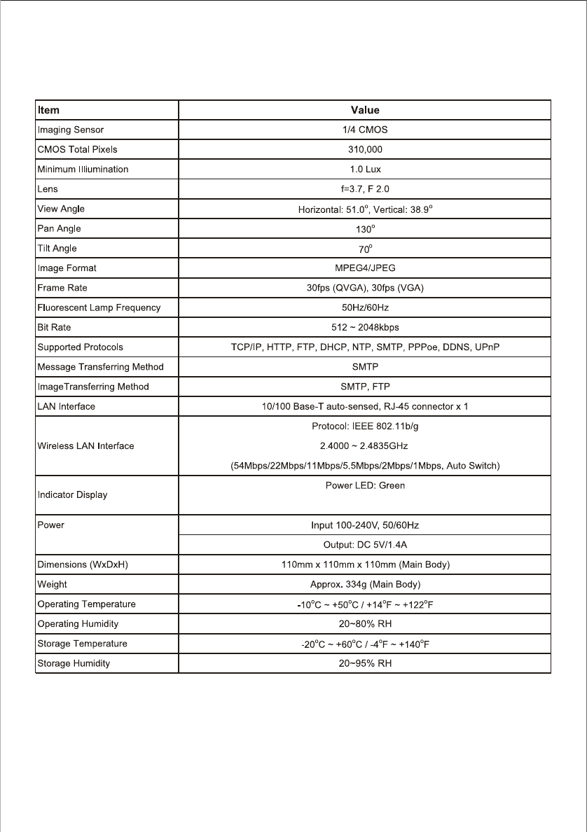
SPECIFICATIONS
* Specifications are subject to minor change without prior notice.
Network LED: Red(Wired Network), Green (Wireless Network)
54

TROUBLESHOOTING
If the Network Camera is not working properly, these suggestions might help you eliminate the problem. If
it still does not help, take it to your local retailer for assistance.
Problem Cause and Remedy
1. Use IP Finder.
2. Use UPNP (only for XP O/S)
3. PPPoE IP Notification can send e-mail to your mailbox
4. Reset your Network to default IP address
Initialize the network camera by pressing the RESET
button.
Pan/Tile function is set as disable.
Enter the setting interface to enable the Pan/Tilt function.
1. Maximum 10 users are allowed to access the camera
simultaneously through network.
2. Network congestion may prevent the viewing interface
from appearing quickly. Wait for a while.
Forget the IP address of network
camera.
Forget the password to access the
setting interface.
The picture viewing interface
does not appear.
Pan/Tilt panel does not work.
Wireless communication
does not work.
1. Signal strength is weak. Relocate the camera or
remove the obstacle around it.
2. Make sure the SSID and Encryption setting shall be
identical.
The color of the picture is strange. Confirm the color setting of PC is 16 bits or more.
The unreadable characters are
displayed.
1. Use the operating system of the selected language;
2. Set the Encoding or the Character Set of the selected
language on the web browser.
55

GLOSSARY
1. Network Camera: A stand-alone device which allows users to view live, full motion video from anywhere on a
computer network, even over the Internet, using a standard web browser.
2. CMOS Sensor: Technology involving Complementary Metal-Oxide Semiconductor (CMOS) to sense images. CMOS
now rivals--and in some cases surpass--CCD technology in dynamic range and noise sensitivity and can offer
improvements in resolution.
3. JPEG: A standard image format, used widely for photographs. Also known as JPG.
4. IEEE 802.11b/g: The specifications developed by the IEEE for wireless network technology. It provides 11 Mbps
transmission in the 2.4GHz band usage.
5. WEP: Wired Equivalent Privacy. A security protocol for wireless network defined in the IEEE 802.11b/g standard. WEP
aims to provide security by encrypting data over radio waves so that it is protected as it is transmitted from one end
point to another.
6. Adhoc Mode: A wireless network system in which devices communicate directly with each other, without the use of a
wireless router.
7. Infrastructure Mode: One of the wireless network system in which devices communicate with each other by first
going through the wireless router.
8. IP Address: The unique 32 bit number assigned to each computer connected to the Internet. IP numbers are used by
the TCP/IP protocol to route packets of data to their destinations.
9. TCP/IP: The collection of "protocols" underlying the functioning of the Internet. Each computer connected to the
Internet is identified by a unique IP Address.
10. SMTP: Simple Mail Transfer Protocol.
11. FTP: File Transfer Protocol. Network cameras equipped with an embedded operating system, such as Linux, can use
FTP to send images to a website.
12. DDNS: DDNS is a method of keeping a domain name linked to a dynamic IP address with your Network Camera. You
can set up your DDNS service and the device will automatically update your DDNS server each time it alter a different
IP address.
13. Time server: A time server consists of a computer networking device that reads the actual time from a reference clock
and distributes this information to its clients using a computer network.
56

AEE TECHNOLOGY CO., LTD.
R