AEG Identifikationssysteme AREH9LF-1 RFID Reader User Manual Manual ARE H9 Full ISO 008
AEG Identifikationssysteme GmbH RFID Reader Manual ARE H9 Full ISO 008
UserManual.wiki
>
AEG Identifikationssysteme
>
AREH9LF-1 User Manual
>
user manual 1
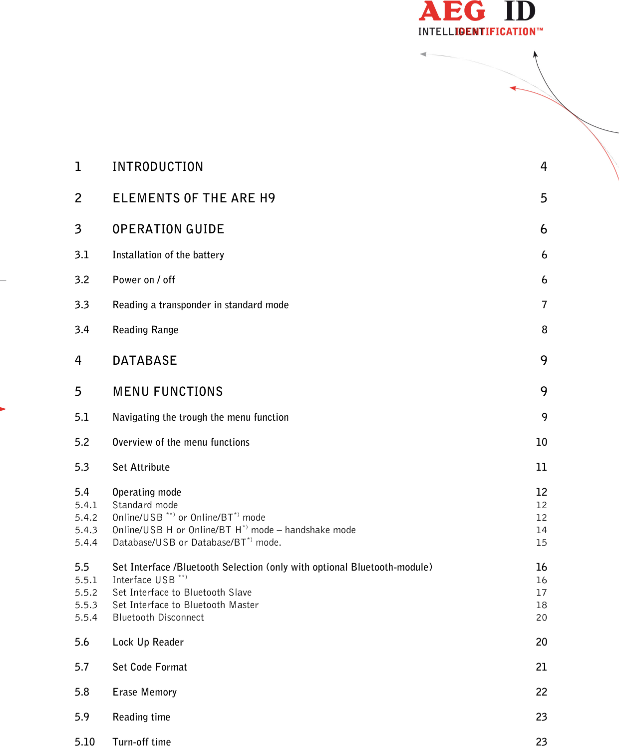
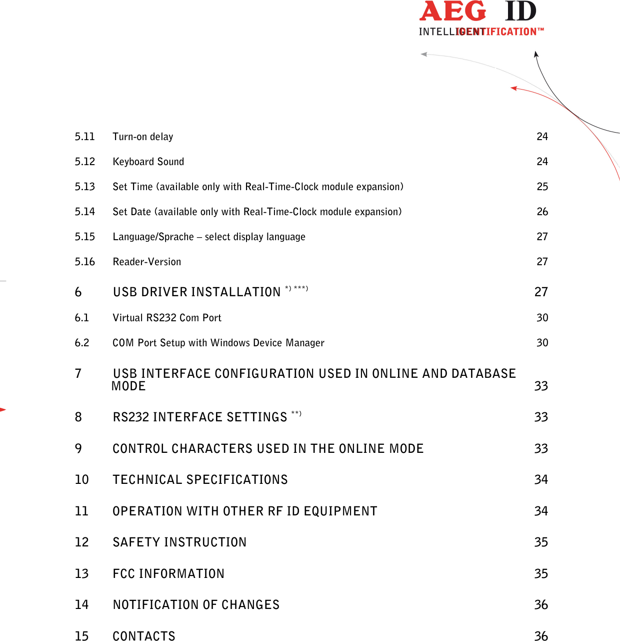
Contents
1.
user manual 1
2.
user manual 2
user manual 1
Navigation menu
Upload a User Manual
Namespaces
Wiki Guide
HTML
PDF
Info
Views
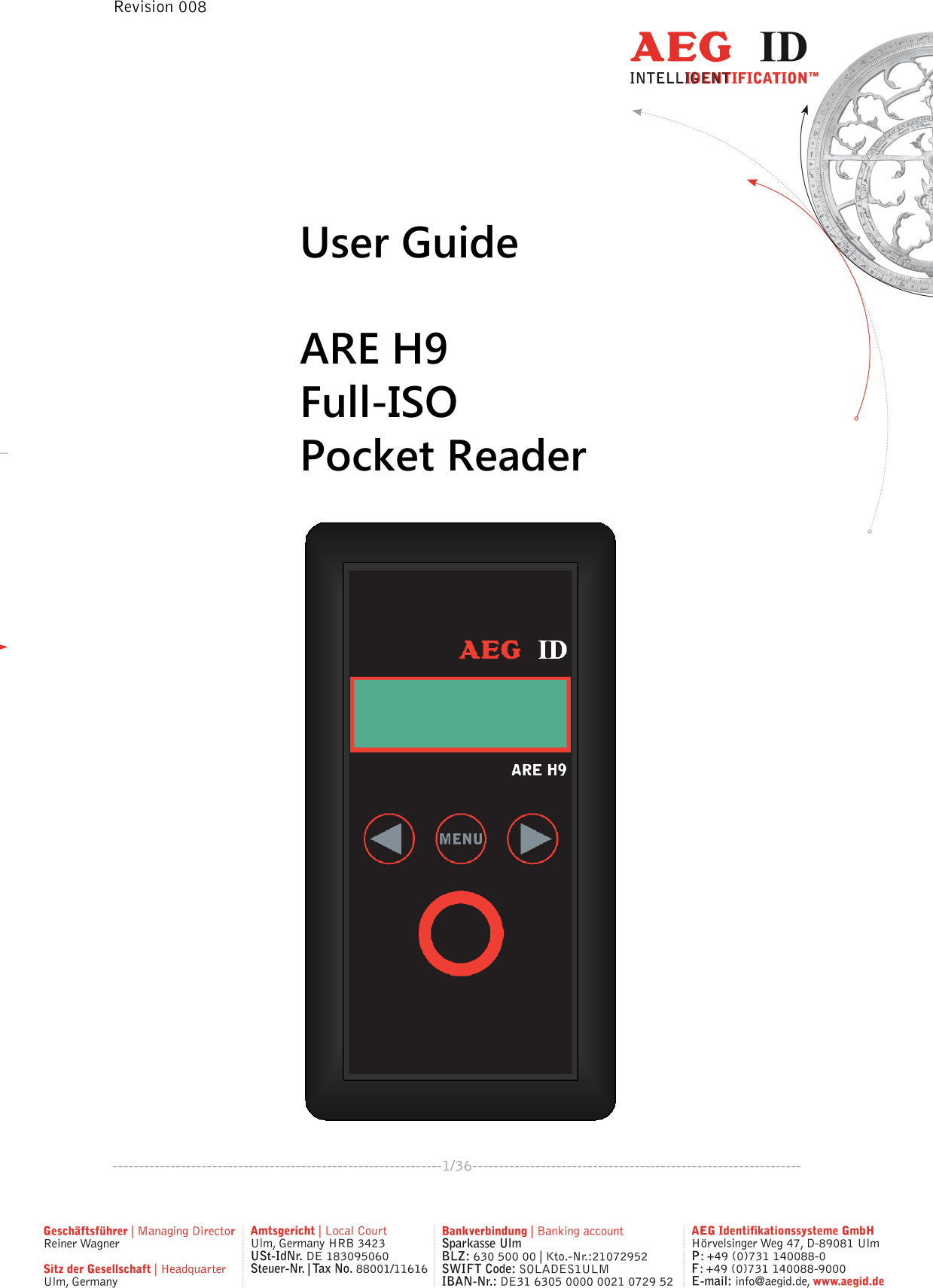
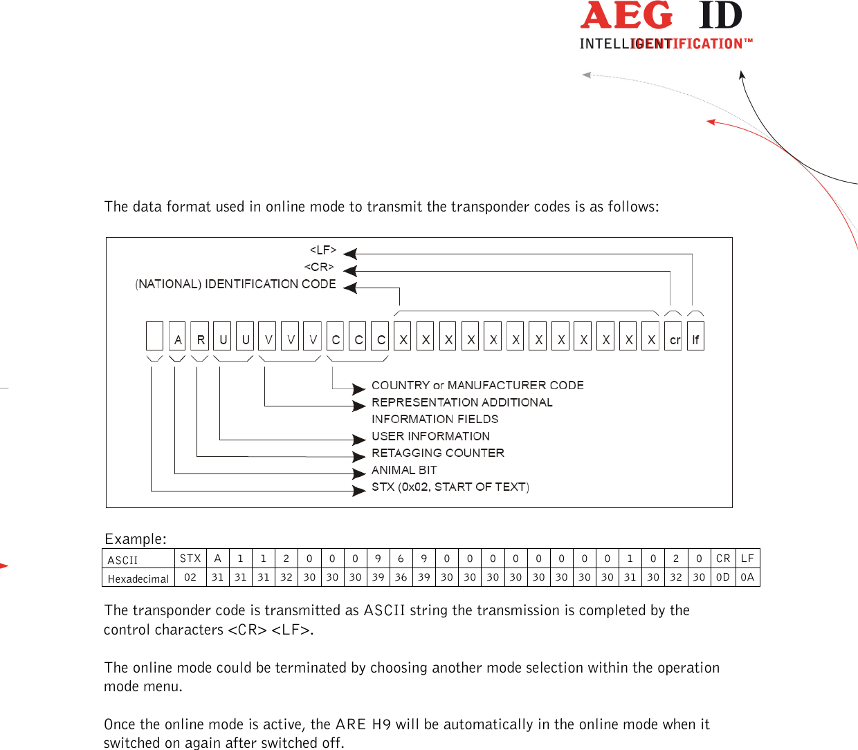
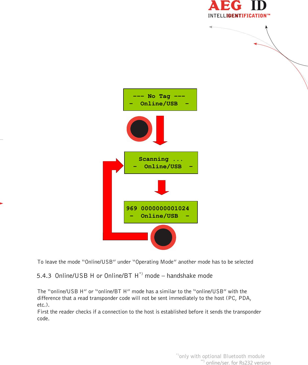
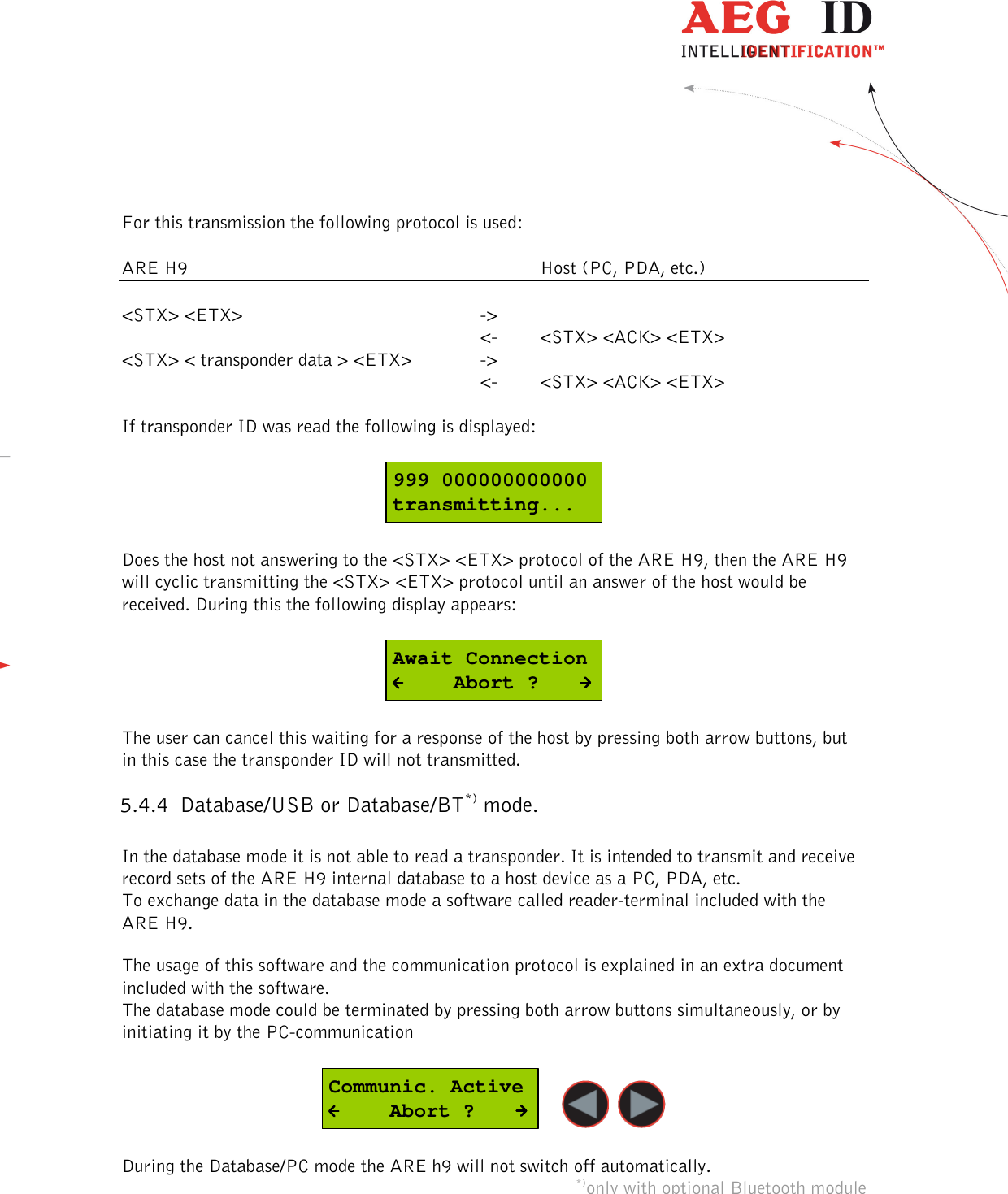
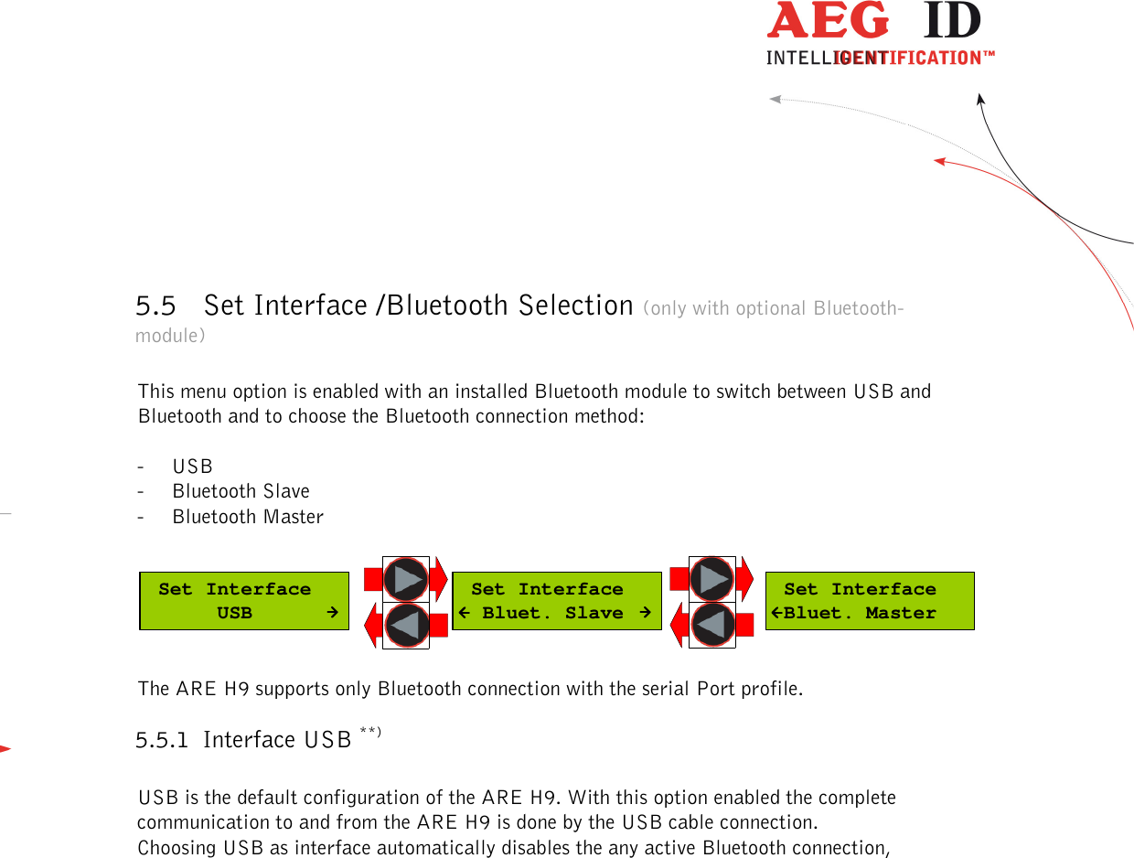
User Manual
Discussion / Help
Navigation