AEG Identifikationssysteme AREH9LF-1 RFID Reader User Manual Manual ARE H9 Full ISO 008
AEG Identifikationssysteme GmbH RFID Reader Manual ARE H9 Full ISO 008
Contents
- 1. user manual 1
- 2. user manual 2
user manual 1
Revision 008
---------------------------------------------------------------1/36---------------------------------------------------------------
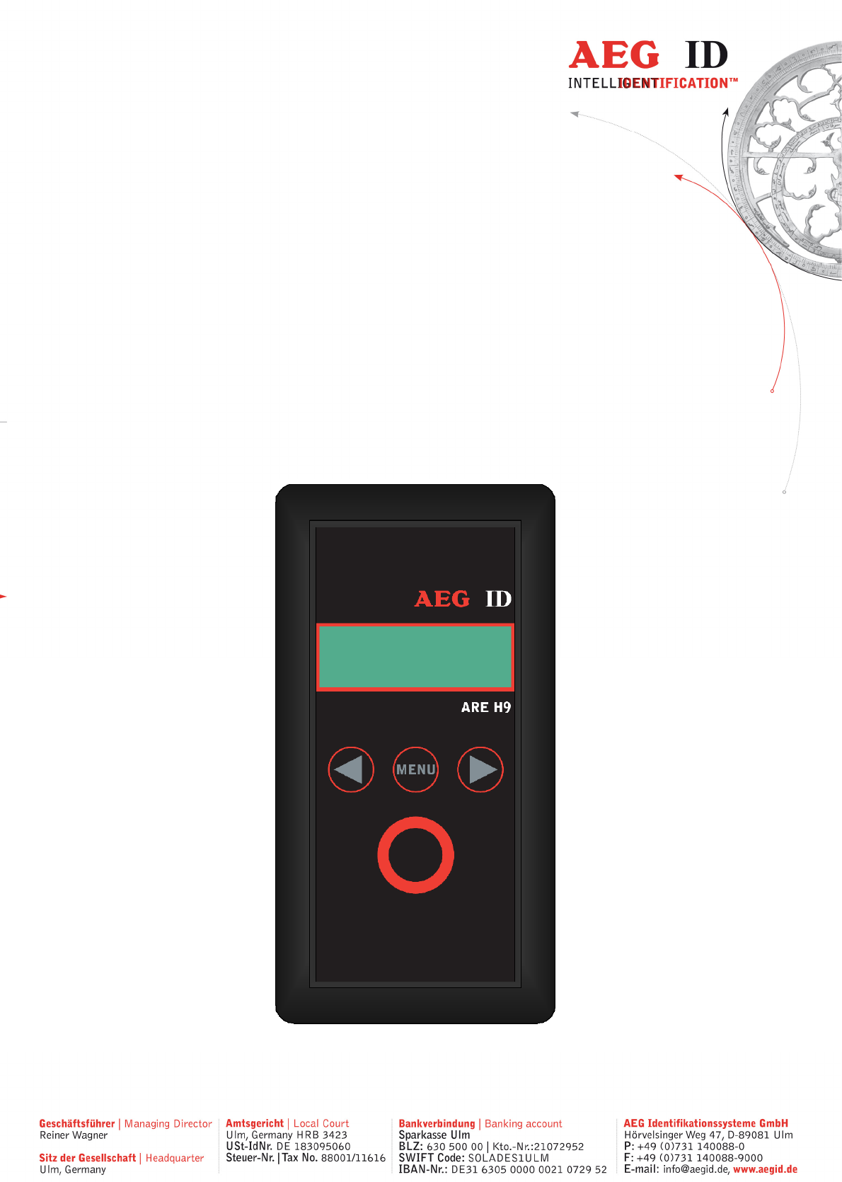
User Guide
ARE H9
Full-ISO
Pocket Reader

---------------------------------------------------------------2/36-------------------------------------------------------------
1 INTRODUCTION 4
2 ELEMENTS OF THE ARE H9 5
3 OPERATION GUIDE 6
3.1 Installation of the battery 6
3.2 Power on / off 6
3.3 Reading a transponder in standard mode 7
3.4 Reading Range 8
4 DATABASE 9
5 MENU FUNCTIONS 9
5.1 Navigating the trough the menu function 9
5.2 Overview of the menu functions 10
5.3 Set Attribute 11
5.4 Operating mode 12
5.4.1 Standard mode 12
5.4.2 Online/USB **) or Online/BT*) mode 12
5.4.3 Online/USB H or Online/BT H*) mode – handshake mode 14
5.4.4 Database/USB or Database/BT*) mode. 15
5.5 Set Interface /Bluetooth Selection (only with optional Bluetooth-module) 16
5.5.1 Interface USB **) 16
5.5.2 Set Interface to Bluetooth Slave 17
5.5.3 Set Interface to Bluetooth Master 18
5.5.4 Bluetooth Disconnect 20
5.6 Lock Up Reader 20
5.7 Set Code Format 21
5.8 Erase Memory 22
5.9 Reading time 23
5.10 Turn-off time 23

---------------------------------------------------------------3/36-------------------------------------------------------------
5.11 Turn-on delay 24
5.12 Keyboard Sound 24
5.13 Set Time (available only with Real-Time-Clock module expansion) 25
5.14 Set Date (available only with Real-Time-Clock module expansion) 26
5.15 Language/Sprache – select display language 27
5.16 Reader-Version 27
6 USB DRIVER INSTALLATION *) ***) 27
6.1 Virtual RS232 Com Port 30
6.2 COM Port Setup with Windows Device Manager 30
7 USB INTERFACE CONFIGURATION USED IN ONLINE AND DATABASE
MODE 33
8 RS232 INTERFACE SETTINGS **) 33
9 CONTROL CHARACTERS USED IN THE ONLINE MODE 33
10 TECHNICAL SPECIFICATIONS 34
11 OPERATION WITH OTHER RF ID EQUIPMENT 34
12 SAFETY INSTRUCTION 35
13 FCC INFORMATION 35
14 NOTIFICATION OF CHANGES 36
15 CONTACTS 36
---------------------------------------------------------------4/36-------------------------------------------------------------
1 Introduction
The ARE H9 is a RFID Pocket Reader designed to read passive Read-Only-Transponder. It has the ability to
store the Transponder-Codes in its internal database.
This Pocket Reader is equipped with a USB Interface **), which allows transmitting single transponder codes
or its entire database to a computer.
It is especially suitable for animal identification, logistics and asset tracking
The ARE H9 Full-ISO is capable to read the following transponder types:
• FDX-B Read-Only(according to ISO 11784/11785)
• HDX-B Read-Only(according to ISO 11784/11785)
• Trovan
• PSK1
• ASK64bit
The ARE H9 does not synchronize with other RFID readers operating in close vicinity.
Before the initial use of this ARE H9 reader please study this manual carefully.
**) RS232 Interface in Rs232 version
---------------------------------------------------------------5/36-------------------------------------------------------------
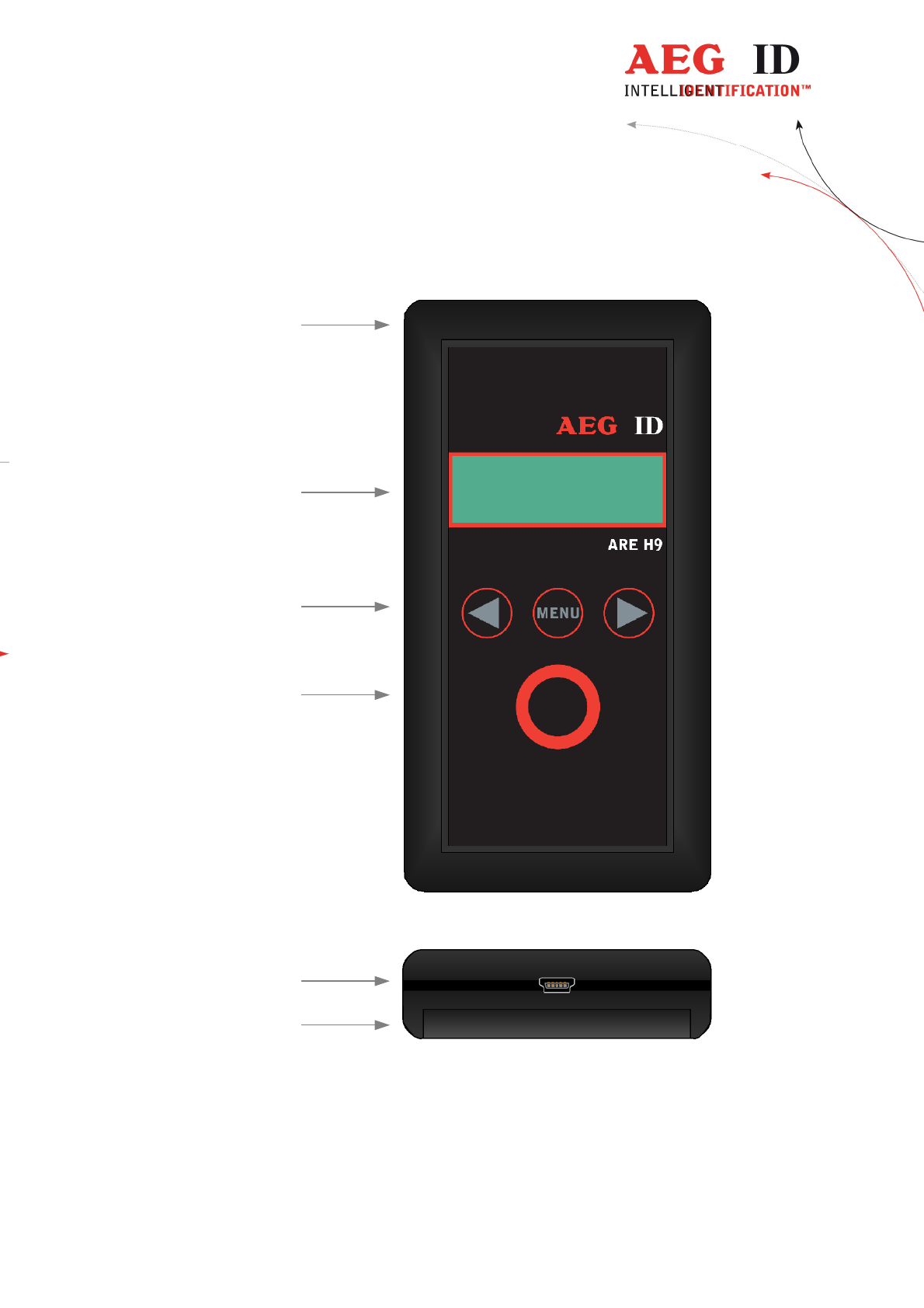
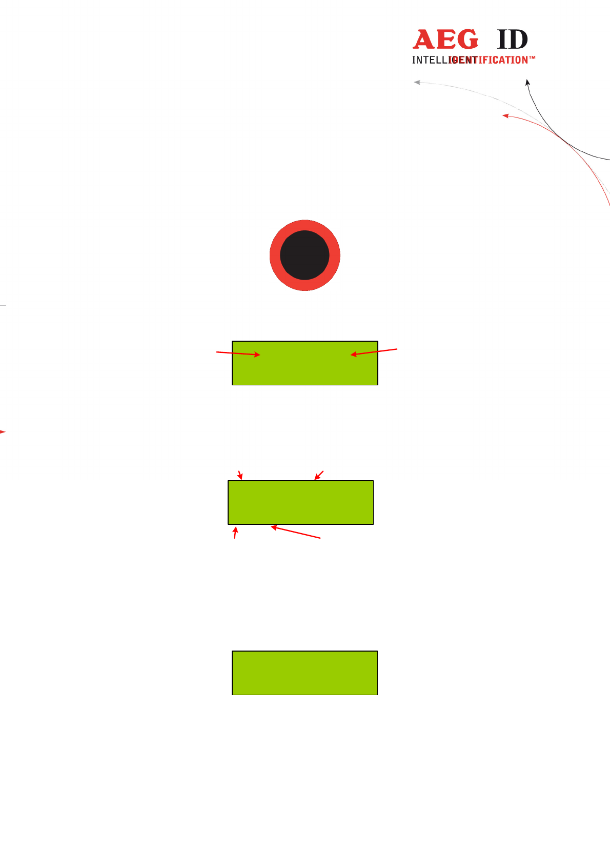
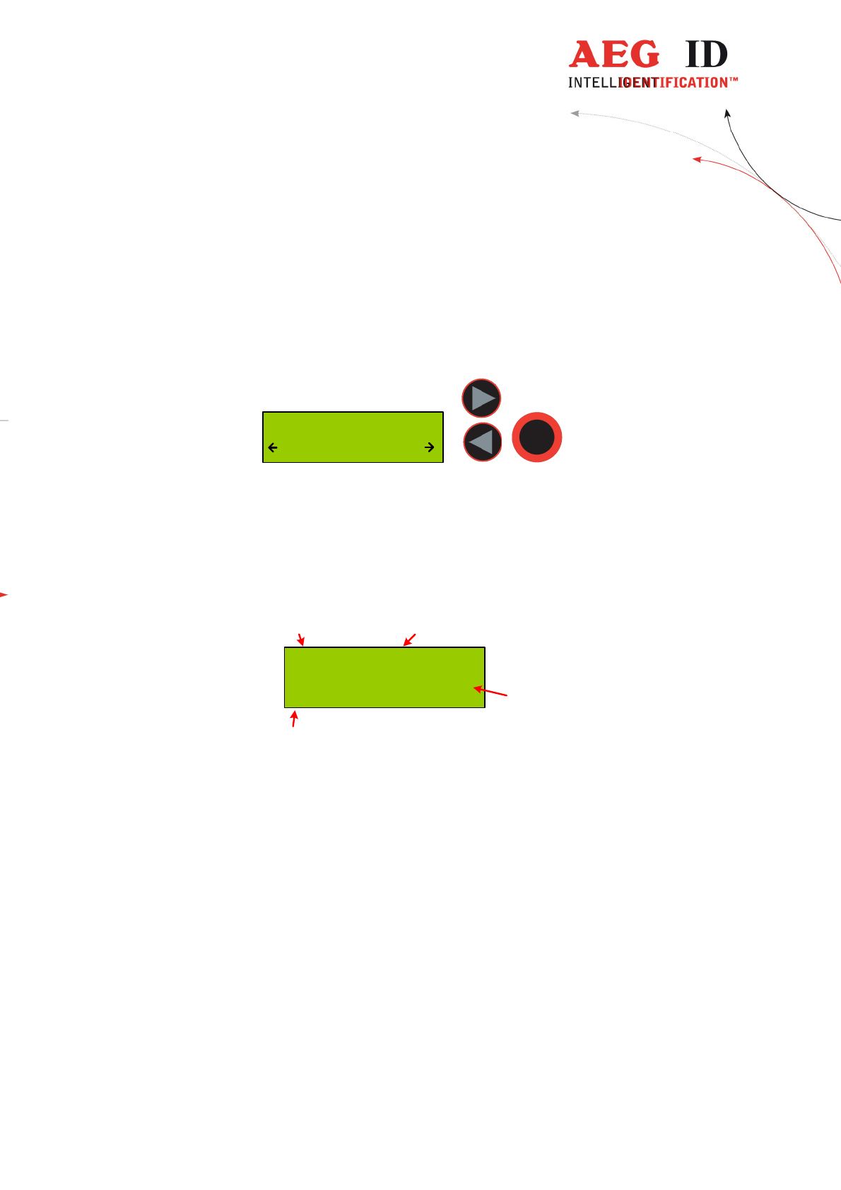
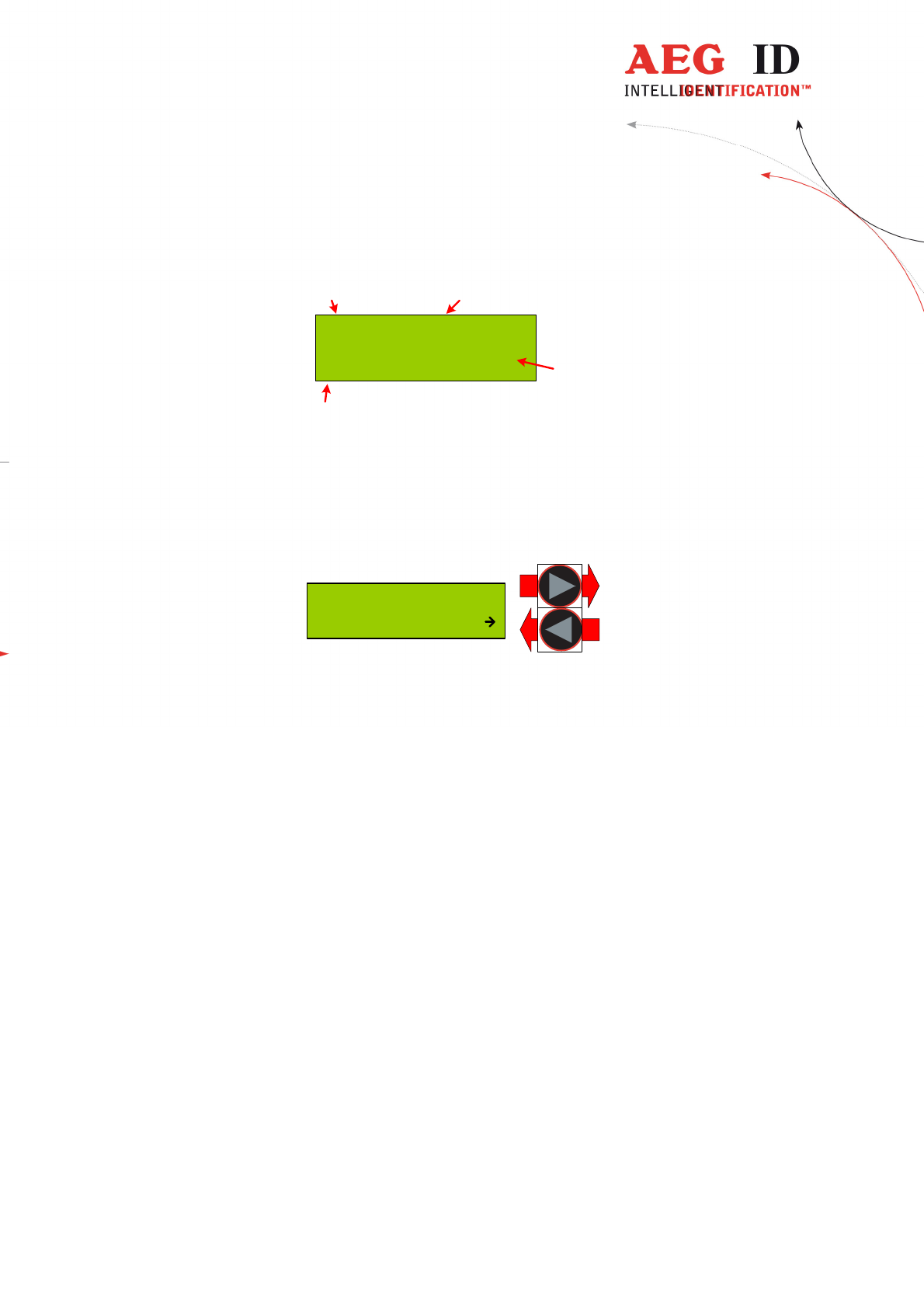
2 Elements of the ARE H9
2x16 Character
LCD-Display
Menu Options Buttons
(left, menu, right)
USB Connector **)
Main Button
(read, select)
Battery
Compartment
Antenna
Position
**) RS232 cable in Rs232 version
---------------------------------------------------------------6/36-------------------------------------------------------------
3 Operation Guide
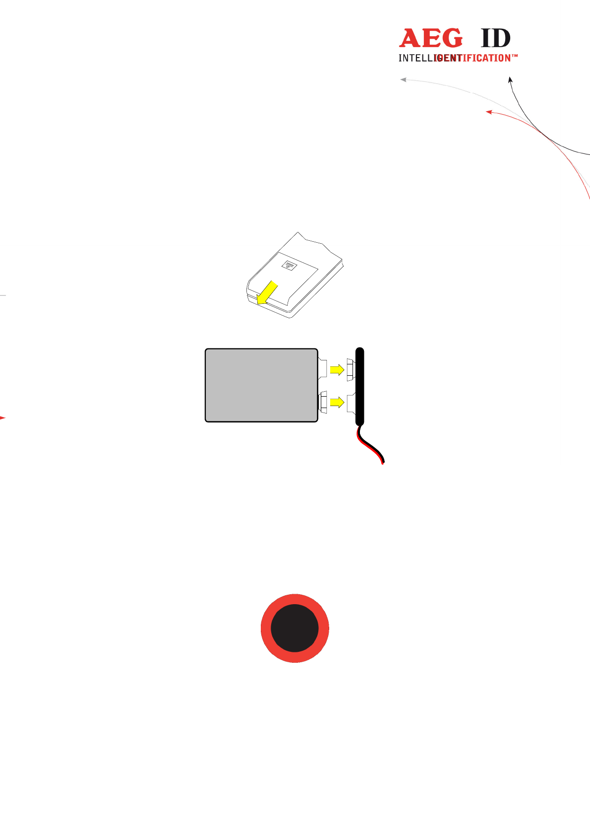
3.1 Installation of the battery
Slide door of the battery compartment to open it.
Attach the Battery to the connector inside. Put the Battery into the compartment.
9V Block
Battery
Battery-clip
-
+
Slide the door back to close it. Use only 9V E-Block alkaline Batteries of the Type 6LR61.
3.2 Power on / off
The Pocket Reader is switched on by pressing the main button for 0,5s (default). The reader starts
in reading mode.
The ARE H9 will switch off automatically after 20s (default) when no button has been pressed
within this time.
---------------------------------------------------------------7/36-------------------------------------------------------------
3.3 Reading a transponder in standard mode
Press the main button to start the reading process.
The ARE H9 starts the reading process and the display shows:
0 of 2016
Scanning Nr. 1
actual
count
maximum
count
Approach a transponder within the readers reading range.
The reader emits a beep when the transponder has been read successfully, and the transponder
code is shown on the display:
969 0000000001024
1 12
Country-Code ID
Retagging Counter and User Information
For ISO Transponder additional the retagging counter and the user information field are displayed
in the second row of the display.
In case no transponder has been read within the given time frame, the reader stops its reading
process and the display shows:
--- No Tag ---
For further reading processes release the main button and press it again for each attempt.
---------------------------------------------------------------8/36-------------------------------------------------------------
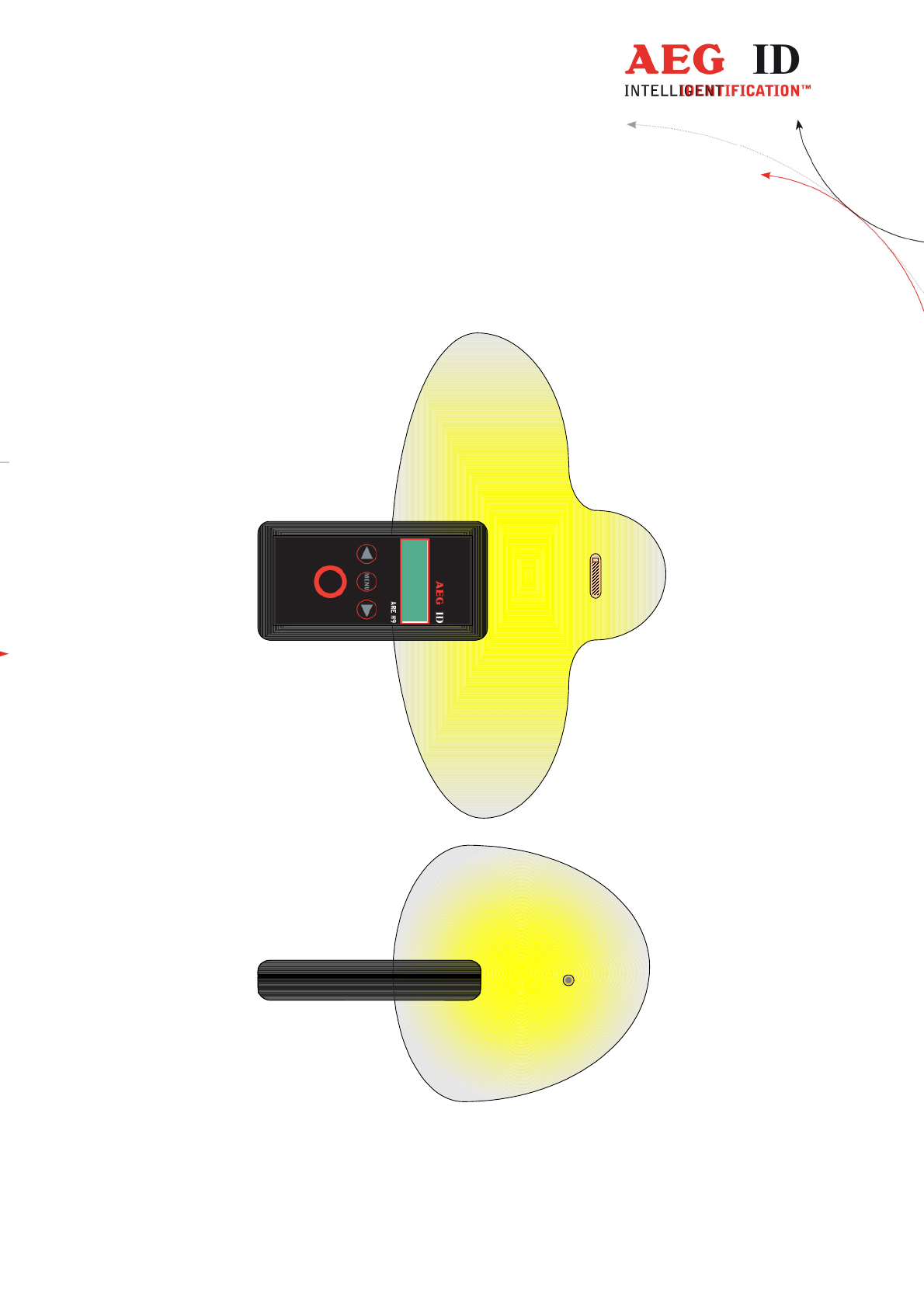
3.4 Reading Range
The reading range and distance depends on the transponder, its packaging and orientation to the
reader. The following diagram shows the typical area where a glass transponder should be read:
The ARE H 9 is not capable to read two or more transponders which are at the same time in the
antenna field.
---------------------------------------------------------------9/36-------------------------------------------------------------
4 Database
When a reading had been accomplished successfully, in the standard operating mode, the ARE H9
internal database will be checked whether this transponder code is already stored.
If the new code, in combination with the attribute, is not found in the database, it will be stored as
a new record. This record is composed of the ID-code, the transponder type, the selected attribute.
With the optional real time clock module date and time of reading will be also stored.
If the new code is already stored in the database, it will be not stored again. In this case the reader
emits 2 successive beeps.
The database is capable to store up to 2016 transponder codes. When the maximum of the storage
is reached no further new code is stored. To store new codes in this case the database has to be
erased.
The database of the ARE H9 with all its actual records could be transmitted to a PC; also it is
possible to receive a new database from a PC. This is done in the Database/USB mode described in
chapter 5.4.4. On Power Loss the ARE H9 will keep its database data.
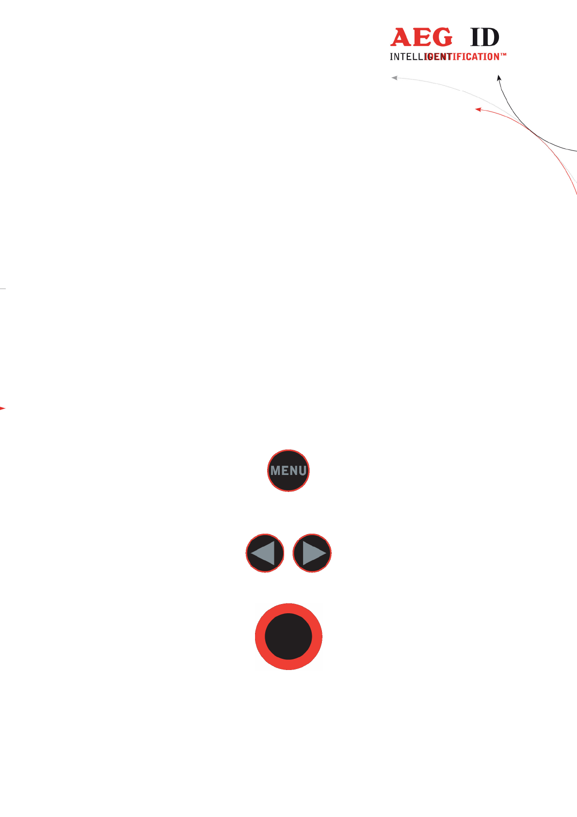
5 Menu Functions
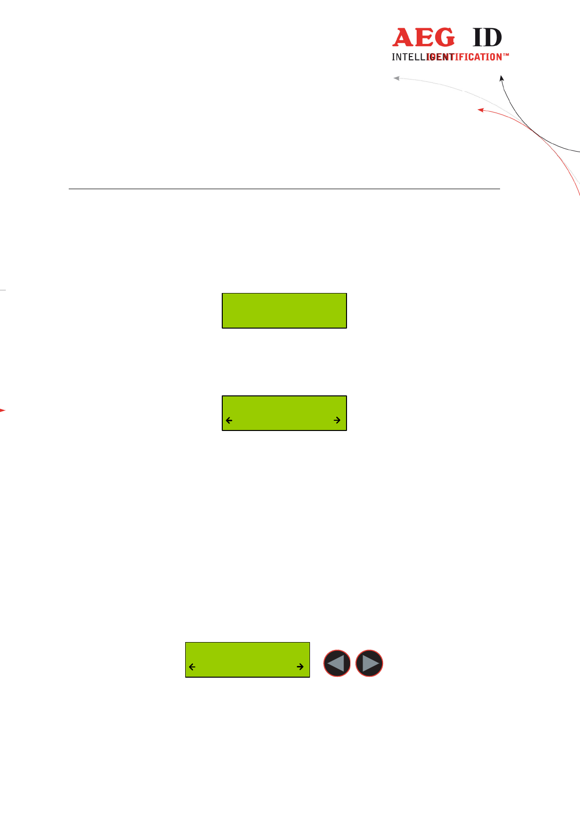
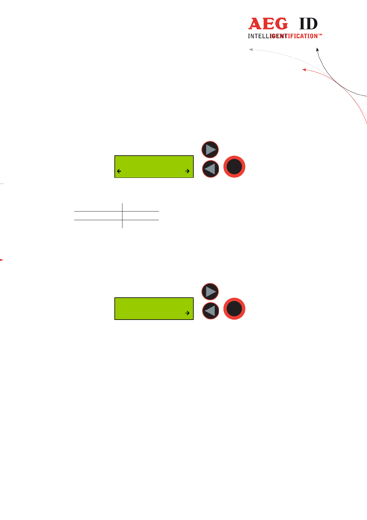
5.1 Navigating the trough the menu function
By pressing the menu button it can be chosen between the different menu function.
If the menu button is pressed again the ARE H9 cyclic changes to the next menu function.
Inside a menu function the setting for the function could be changed with the arrow buttons.
With the main button the actual menu function setting is selected and the ARE H9 changes back to
the transponder reading mode.
---------------------------------------------------------------10/36-------------------------------------------------------------
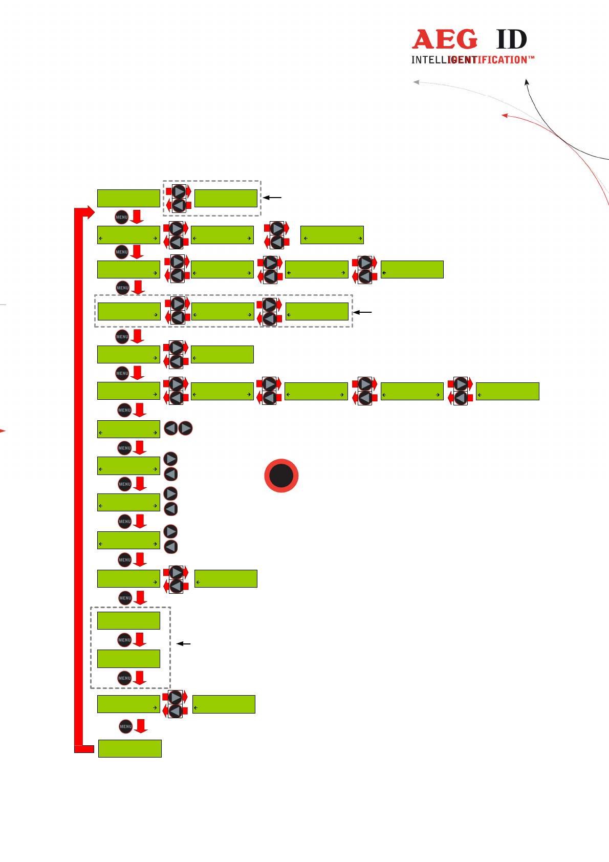
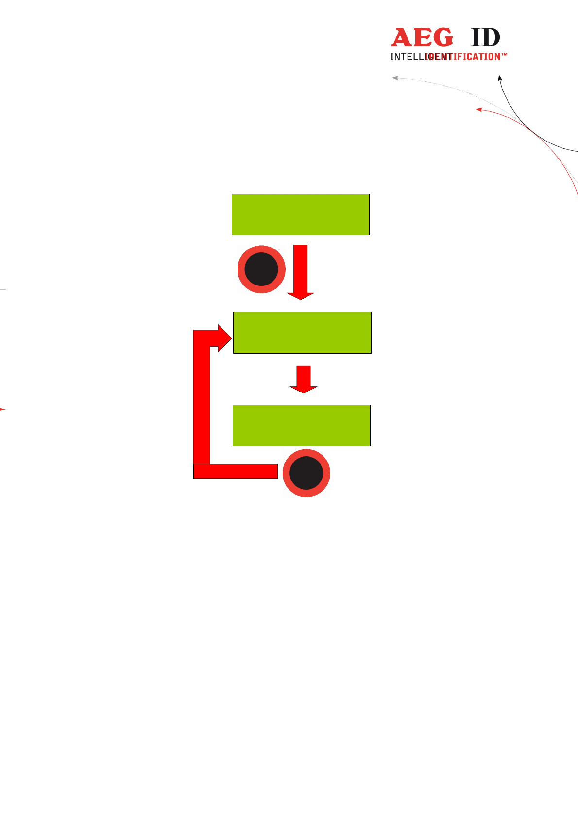
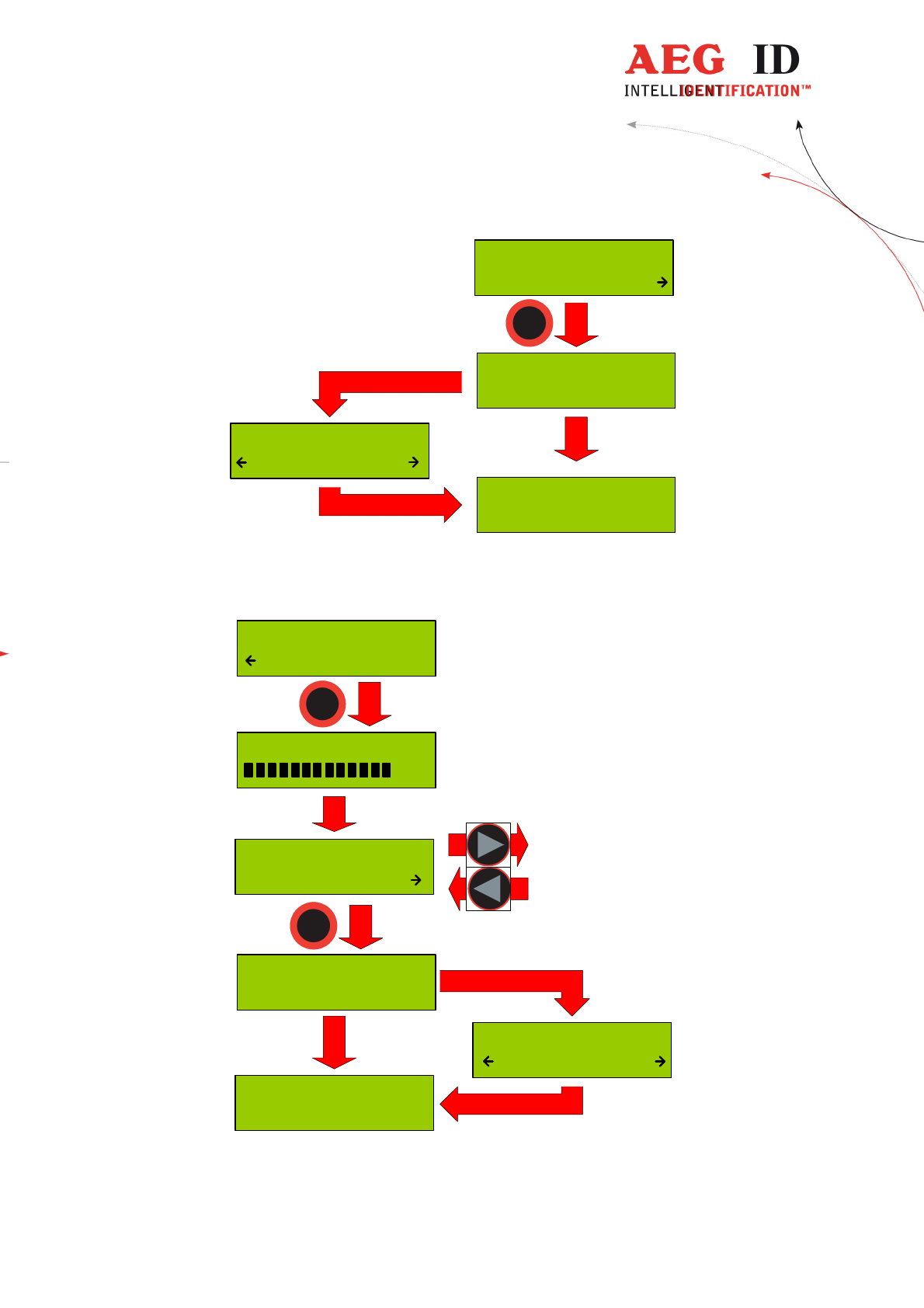
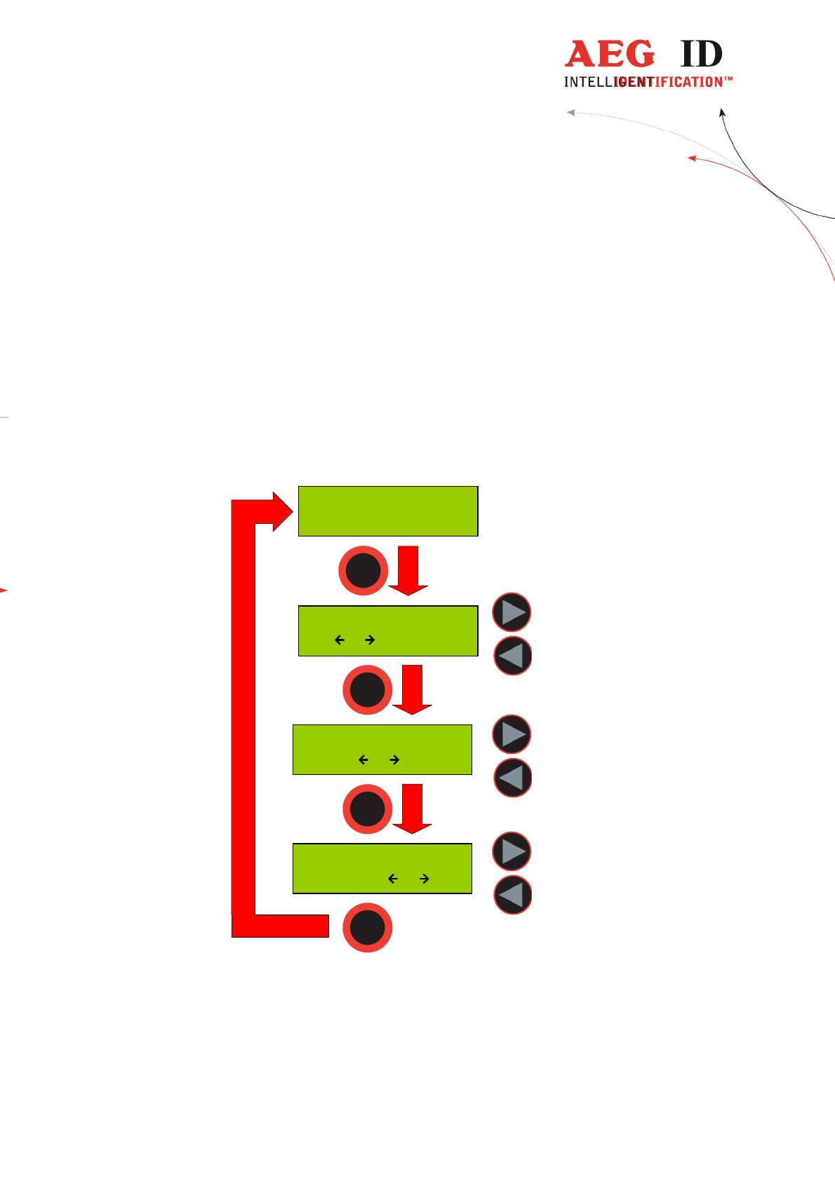
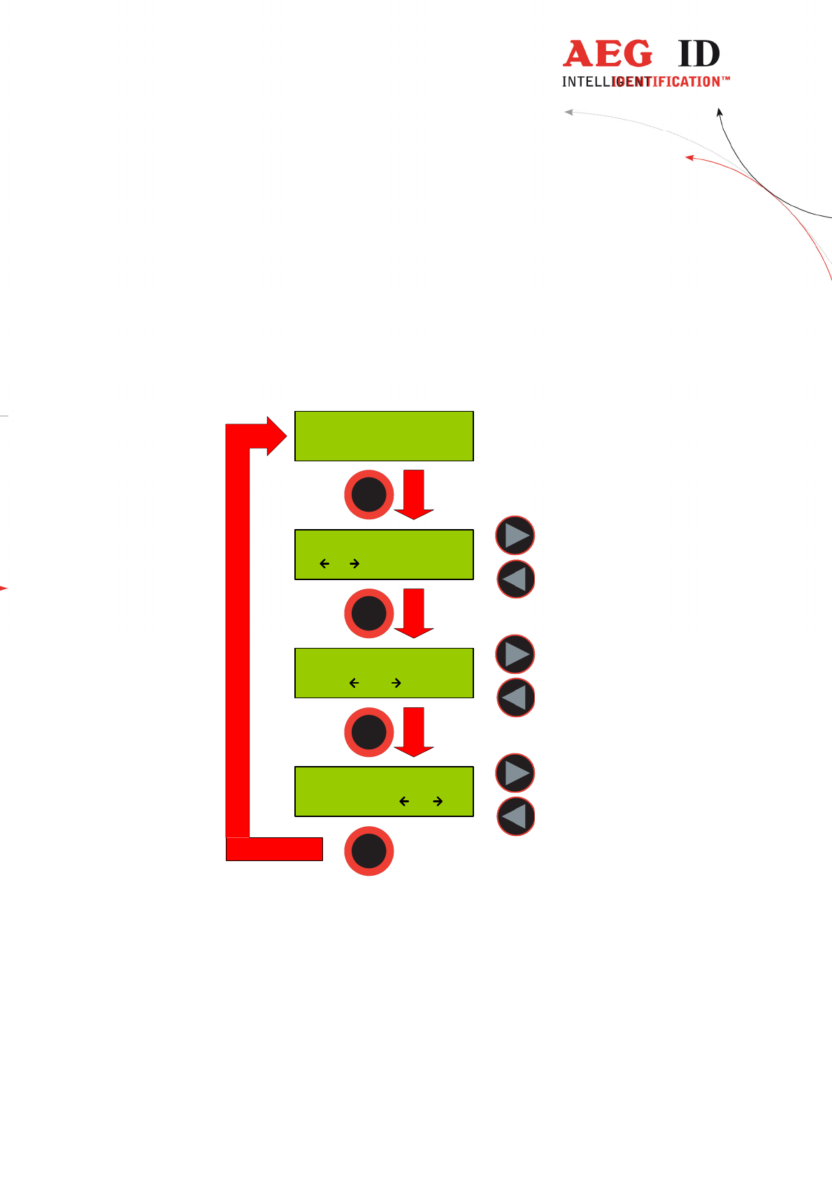
5.2 Overview of the menu functions
Press both arrow
buttons to erase
database memory
+ 0.5 s
- 0.5 s
+ 5 s
- 5 s
+ 0.5 s
- 0.5 s
Press the main
button to select
actual menu option
... ...
Set Code Format
ISO Animal
Set Code Format
ISO Industry
Set Code Format
BDE-Format
Lock Up Reader
Lock
Lock Up Reader
Unlocked
Operating Mode
Standard
Operating Mode
Online/USB
Operating Mode
Datenbank/USB
Set Attribute
#
Set Attribute
A
Set Attribute
Z
--- No Tag ---
Erase DB-Memory
Confirm ?
Reading Time
2.0 s
Turn-Off Time
20 s
Turn-On Delay
0.5 s
Keyboard Sound
Off
Keyboard Sound
On
Set Time
12:00:00
Set Date
01 Jan '10
01 Jan '10
12:00:00
available only with
Real-Time-Clock
module
available only with Real-
Time-Clock module
Set Code Format
ISO Attributs
Set Code Format
Hexadecimal
AEG ID - ARE H9
V3.00200
Language/Sprache
Deutsch
Language/Sprache
English
available only with
optional Bluetooth
module
Operating Mode
Online/USB H
Set Interface
USB
Set Interface
Bluet. Slave
Set Interface
Bluet. Master
---------------------------------------------------------------11/36-------------------------------------------------------------
5.3 Set Attribute
With set attribute one of 27 attributes could be selected for the next read transponder.
The selection is done by the left/right arrow buttons and confirmed by pressing the main button.
Set Attribute
#
In standard read mode this selected attribute will be stored together with the transponder ID-
code of the next read transponder in the internal database of the ARE H9. When the Code
Format is set to Attributes will the selected attribute or its text displayed in the rightmost
corner of the second display line.
Example of Transponder-ID with no attribute:
969 0000000001024
ISO-Fdx #
Country-Code ID
type of trasnponder
attribute
In the initial configuration all the 27 attributes available have a standard text assignment.
#, A, B, C,D,E,F,G,H,I,J,K,L,M,N,O,P,Q,R,S,T,U,V,W,X,Y,Z
With a PC-software and using the Database/PC mode of the ARE H9 it is possible to assign each
attribute a custom text with up to 14 ASCII characters.
Example:
A becomes "stable",
B becomes "pasture"
C becomes "vaccination"
Under Set Attribute at the ARE H9 it is now possible to select the attribute by this custom text.
When a transponder has been read with a attribute set up with a custom text, the text assigned to the
attribute will now be shown on the lower line of the display, right justified, instead of the attribute.
---------------------------------------------------------------12/36-------------------------------------------------------------
Example of Transponder-ID with attribute and assigned text “Stall”:
969 0000000001024
ISO-Fdx Stall
Country-Code ID
type of transponder
attribute
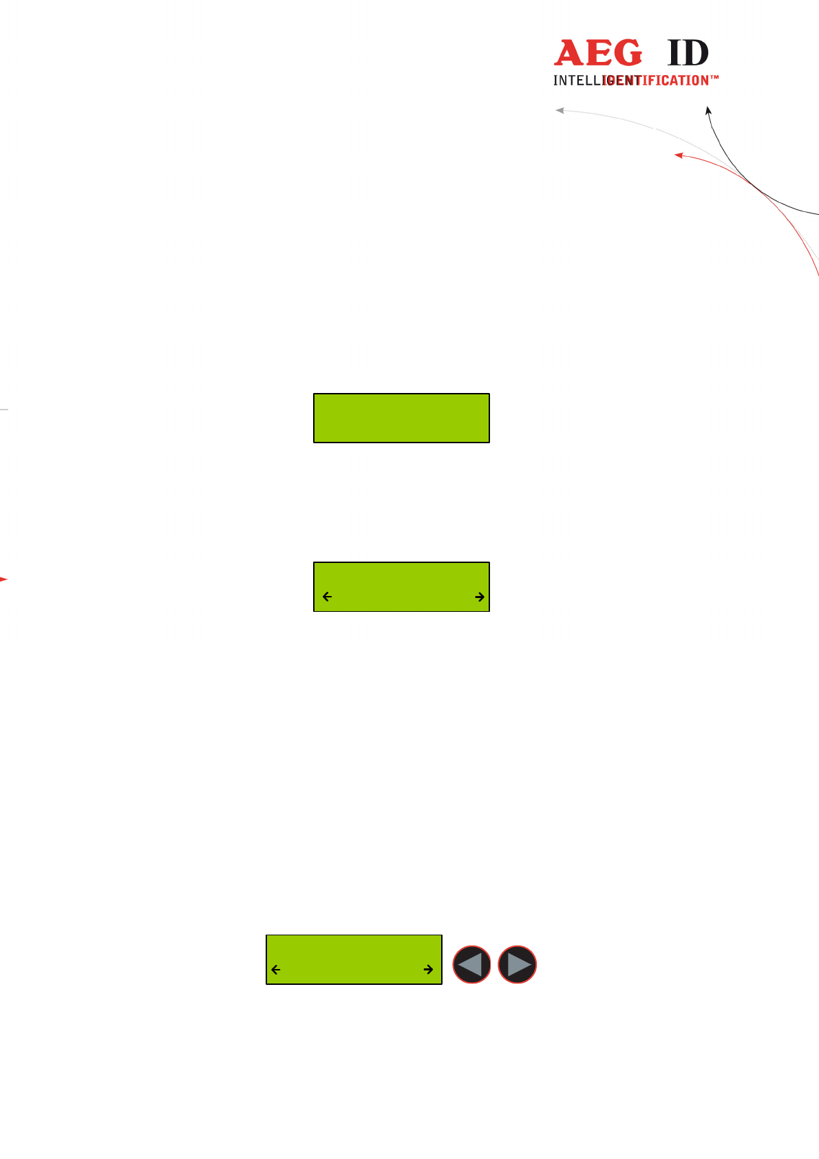
5.4 Operating mode
The menu "Operating Mode" switches between the following modes: Standard, Online/USB mode
and Database/USB mode.
Operating Mode
Standard
5.4.1 Standard mode
In the standard mode will the read transponder codes stored into the internal database of the
ARE H9. For a detailed description see section 3.3 and 4.
5.4.2 Online/USB **) or Online/BT*) mode
In the online mode the transponder codes will not be stored into the internal database of the
ARE H9. The transponder codes are immediately transmitted via the USB interface to an
attached PC, PDA, etc.
It is important that there is a USB **) or Bluetooth*) connection established to a host-device
ready to receive the data; otherwise the read transponder codes are lost because they are not
stored in this mode.
The reading process is the same as in standard mode; the second display-line shows the
information of the selected “online/USB” **) or “online/BT” mode in between the reading
processes.
*)only with optional Bluetooth module
**) Ser. for Rs232 version
---------------------------------------------------------------13/36-------------------------------------------------------------
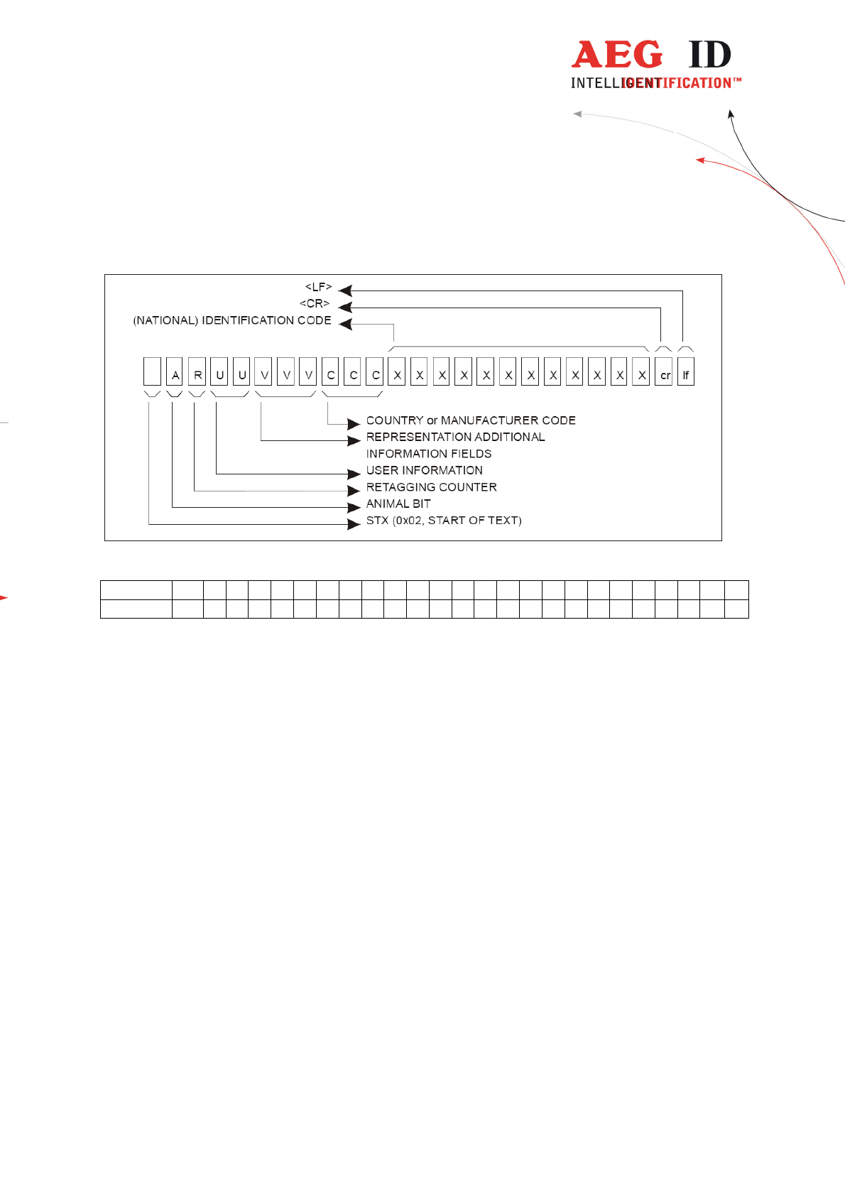
The data format used in online mode to transmit the transponder codes is as follows:
Example:
ASCII STX
A 1 1 2 0 0 0 9 6 9 0 0 0 0 0 0 0 0 1 0 2 0 CR
LF
Hexadecimal
02 31
31
31
32
30
30
30
39
36
39
30
30
30
30
30
30
30
30
31
30
32
30
0D
0A
The transponder code is transmitted as ASCII string the transmission is completed by the
control characters <CR> <LF>.
The online mode could be terminated by choosing another mode selection within the operation
mode menu.
Once the online mode is active, the ARE H9 will be automatically in the online mode when it
switched on again after switched off.
---------------------------------------------------------------14/36-------------------------------------------------------------
--- No Tag ---
- Online/USB -
Scanning ...
- Online/USB -
969 0000000001024
- Online/USB -
To leave the mode “Online/USB” under “Operating Mode” another mode has to be selected
5.4.3 Online/USB H or Online/BT H*) mode – handshake mode
The “online/USB H” or “online/BT H” mode has a similar to the “online/USB” with the
difference that a read transponder code will not be sent immediately to the host (PC, PDA,
etc.).
First the reader checks if a connection to the host is established before it sends the transponder
code.
*)only with optional Bluetooth module
**) online/ser. for Rs232 version
---------------------------------------------------------------15/36-------------------------------------------------------------
For this transmission the following protocol is used:
ARE H9 Host (PC, PDA, etc.)
<STX> <ETX> ->
<- <STX> <ACK> <ETX>
<STX> < transponder data > <ETX> ->
<- <STX> <ACK> <ETX>
If transponder ID was read the following is displayed:
999 000000000000
transmitting...
Does the host not answering to the <STX> <ETX> protocol of the ARE H9, then the ARE H9
will cyclic transmitting the <STX> <ETX> protocol until an answer of the host would be
received. During this the following display appears:
Await Connection
Abort ?
The user can cancel this waiting for a response of the host by pressing both arrow buttons, but
in this case the transponder ID will not transmitted.
5.4.4 Database/USB or Database/BT*) mode.
In the database mode it is not able to read a transponder. It is intended to transmit and receive
record sets of the ARE H9 internal database to a host device as a PC, PDA, etc.
To exchange data in the database mode a software called reader-terminal included with the
ARE H9.
The usage of this software and the communication protocol is explained in an extra document
included with the software.
The database mode could be terminated by pressing both arrow buttons simultaneously, or by
initiating it by the PC-communication
Communic. Active
Abort ?
During the Database/PC mode the ARE h9 will not switch off automatically.
*)only with optional Bluetooth module
**) database/ser. for Rs232 version
---------------------------------------------------------------16/36-------------------------------------------------------------
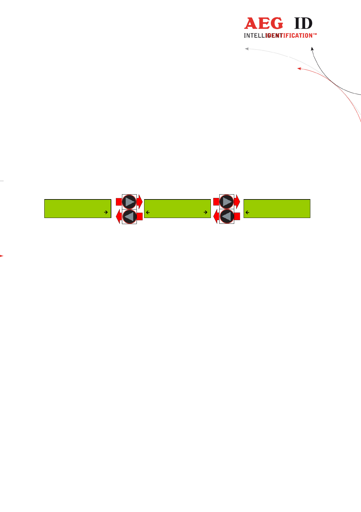
5.5 Set Interface /Bluetooth Selection (only with optional Bluetooth-
module)
This menu option is enabled with an installed Bluetooth module to switch between USB and
Bluetooth and to choose the Bluetooth connection method:
- USB
- Bluetooth Slave
- Bluetooth Master
Set Interface
USB
Set Interface
Bluet. Slave
Set Interface
Bluet. Master
The ARE H9 supports only Bluetooth connection with the serial Port profile.
5.5.1 Interface USB **)
USB is the default configuration of the ARE H9. With this option enabled the complete
communication to and from the ARE H9 is done by the USB cable connection.
Choosing USB as interface automatically disables the any active Bluetooth connection,
**) serial for Rs232 version
---------------------------------------------------------------17/36-------------------------------------------------------------
5.5.2 Set Interface to Bluetooth Slave
This menu option configures the ARE H9 as Bluetooth slave. With the ARE H9 as Bluetooth
Slave the Bluetooth-connection is established up by the Bluetooth-partner which is configured as
master.
The ARE H9 checks after the selection of this option if there is an active Bluetooth connection,
in this case this connection will be closed.
Then the ARE H9 is waiting until a Bluetooth connection is established or the user cancels the
operation by pressing both arrow buttons. During this operation the ARE H9 will not switch off
automatically.
Verify Blutooth
Connection
Await Connection
Abort ?
Closing active
Connection
Connected as
BT Slave
Set Interface
Bluet. Slave
---------------------------------------------------------------18/36-------------------------------------------------------------
5.5.3 Set Interface to Bluetooth Master
This menu option configures the ARE H9 as Bluetooth master. In this configuration an
Bluetooth connection with an partner is established by the ARE H9.
In case there is still an active Bluetooth connection, this connection will be closed before a new
one is established.
BluetoothPartner
PC_007
Verify Bluetooth
Connection
Closing active
Connection
Set Interface
Bluet. Master
Was there a Bluetooth partner for the master connection configured before, this partner will be
displayed as default option in the following dialog.
BluetoothPartner
new search
BluetoothPartner
PC_007
By pressing the arrow keys it is possible to switch the selection between the default partner and
a new partner search.
By choosing the default partner, the ARE H9 will try to establish a connection.
During this process the message “Await Connection” could appear, this is the case when the
partner is not ready or at the partner side additional activities are necessary.
---------------------------------------------------------------19/36-------------------------------------------------------------
BT Connecting to
PC_007
Connected with
PC_007
Await Connection
Abort ?
BluetoothPartner
PC_007
“new Search” starts a search process for Bluetooth devices in range of the ARE H9.
The Bluetooth device search could last some seconds.
Bluetooth Search
2
New BT Partner
PC_007
BT connecting to
PC_007
Connected with
PC_007
Await Connection
Abort ?
BluetoothPartner
new search
---------------------------------------------------------------20/36-------------------------------------------------------------
Was the search successful a selection of possible partners will be shown. The Bluetooth partner
search can’t detect if a Bluetooth device supports the serial port profile, the user has to know
this. Was the search not successful the ARE H9 switches back to the “Set Interface” menu.
After choosing a partner from the found devices, the ARE H9 will try to establish a connection.
During this process the message “Await Connection” could appear, this is the case when the
partner is not ready or at the partner side additional activities are necessary.
A successful connection will be shown as follows:
Connected with
PC_007
5.5.4 Bluetooth Disconnect
Is the connection to the Bluetooth partner lost during the operating of the ARE H9, or
maximum Bluetooth distance has exceeded, the following display appears:
Await Connection
Abort ?
In this case will the ARE H9 wait as long as the connection is established again ort he user
cancels this screen by pressing both arrow buttons.
While switching off the ARE H9 the Bluetooth connection to a partner will automatically
disconnected.
5.6 Lock Up Reader
When lock up reader is activated the ARE H9 switches of immediately. After switching on the
pocked reader again it shows that it is locked.
During the ARE H9 is locked neither a reading process could started nor the menu could be
accessed.
While it is not unlocked, it will switch off again after 5 (default) seconds no button is pressed.
To leave this mode press both arrow buttons simultaneously.
Unlock Reader !
Press Both
---------------------------------------------------------------21/36-------------------------------------------------------------
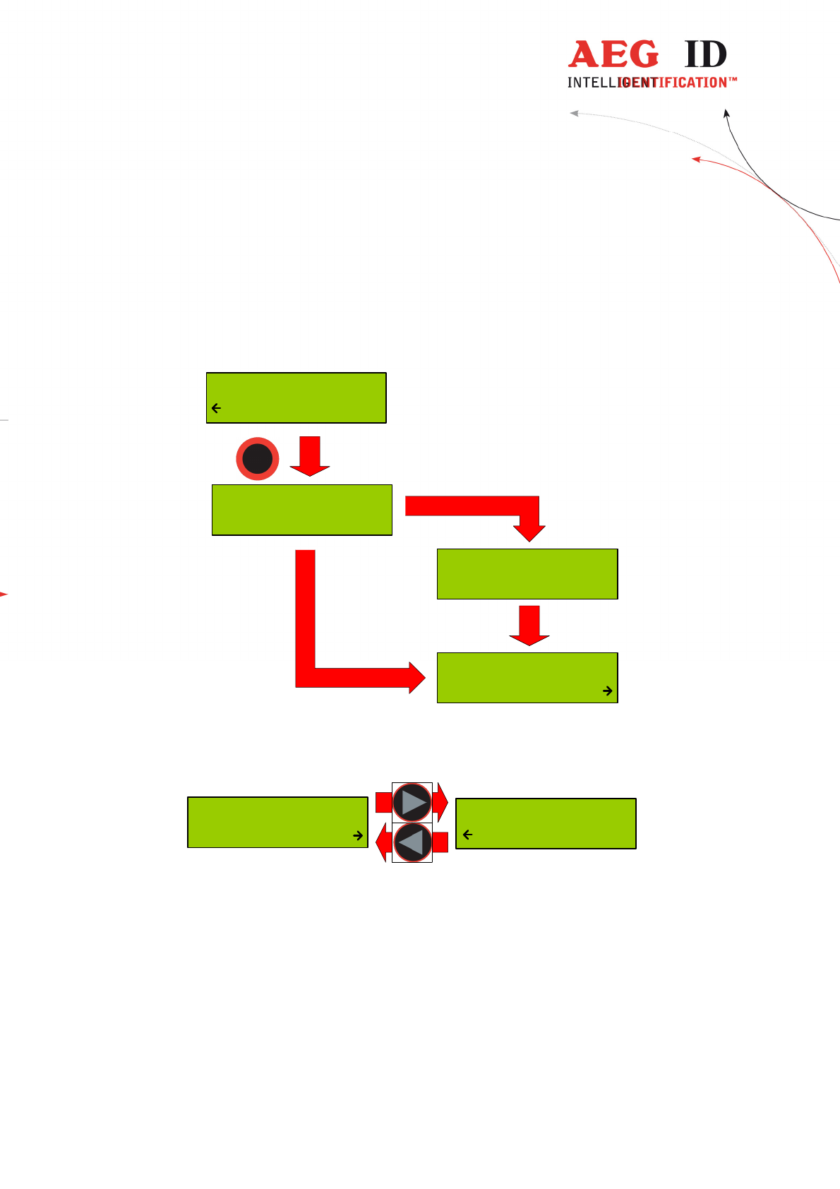
5.7 Set Code Format
This menu option sets the format of representation of ISO-code. The ARE H9 currently supports
three code formats.
ISO Animal code format for ISO-FDX and ISO-HDX
ISO Industry code format for ISO-FDX and ISO-HDX
ISO BDE code format for ISO-FDX for waste management
ISO Attributs for ISO-FDX and ISO-HDX with attribute display
(Like the former H5 display)
Hexadecimal for Trovan, PSK1, ASK 64bit, ISO-FDX and ISO-HDX
Set Code Format
ISO Animal
The selection sets the way in which the transponder code is displayed.
This option has no influence to the reading function; it only filters how the read ID-code is
displayed. This setting has only impact to ISO-FDX and ISO HDX transponders.
For example, if code format is set to “ISO-Animal” and an ISO transponder without animal bit
is read the ARE H9 will signal this with 3 beeps and the following display:
No ISO Animal
ISO-Fdx
The ARE H9 selects automatically the hexadecimal display if a Trovan, PSK1 or Ask64Bit
transponder is read.
This setting is stored in the device and is still valid after power off/on operation.
---------------------------------------------------------------22/36-------------------------------------------------------------
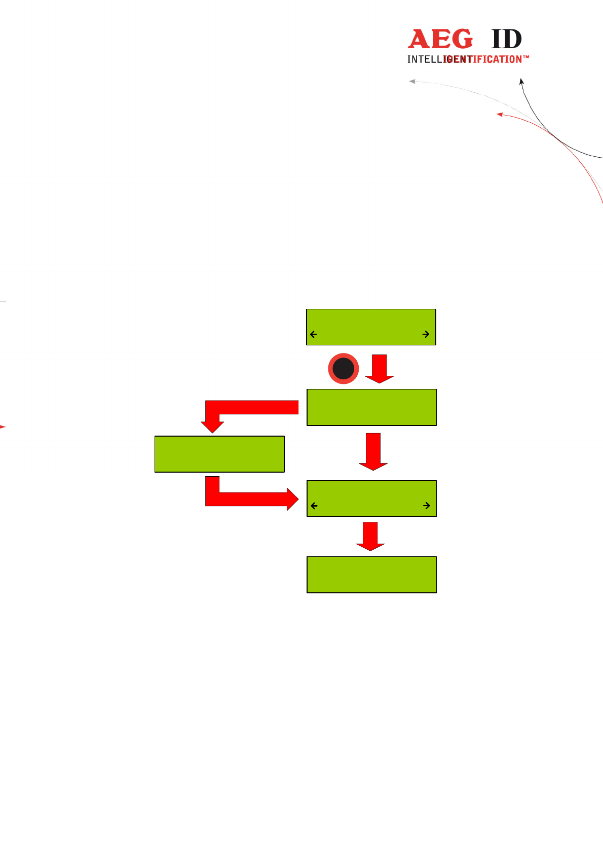
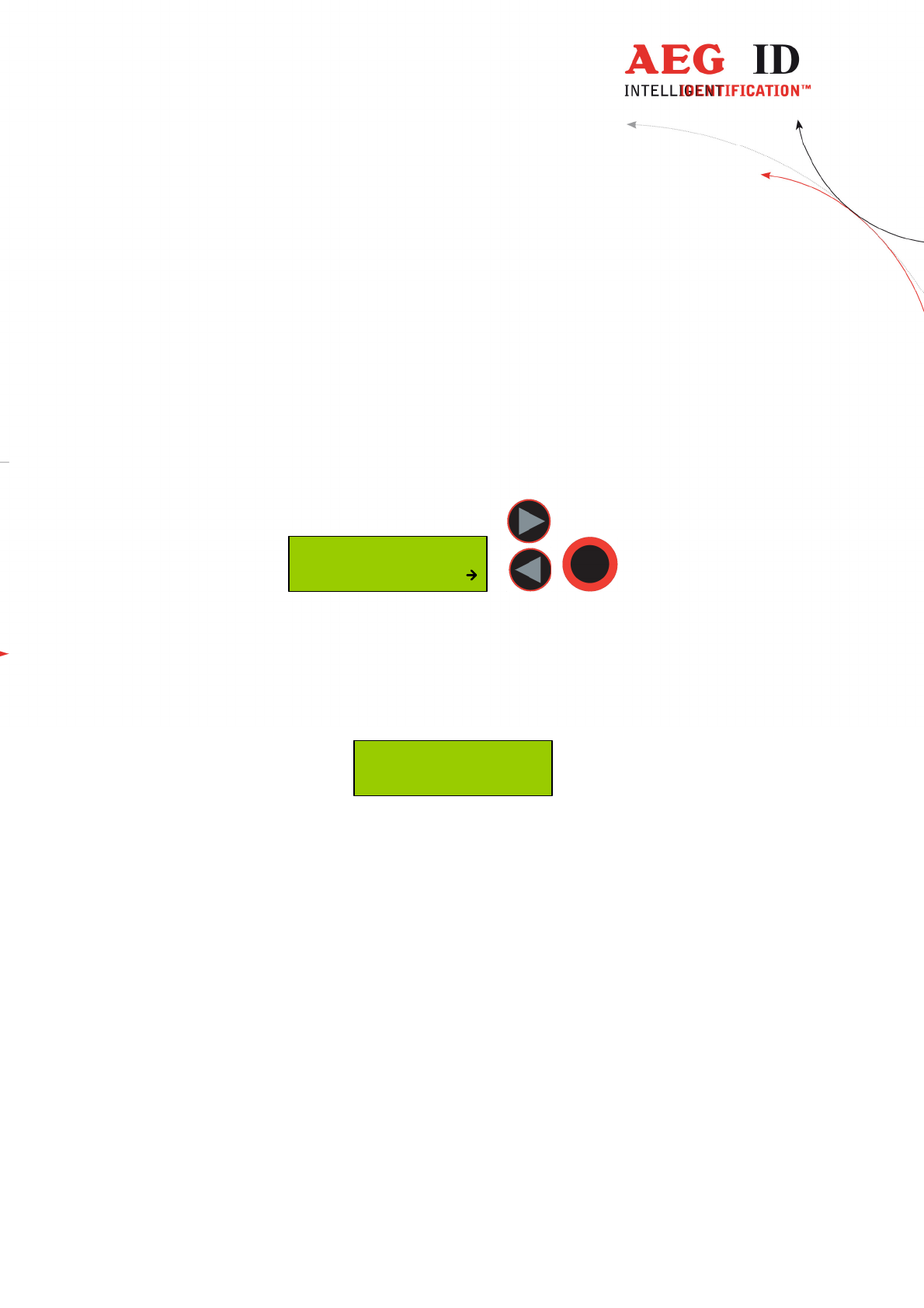
5.8 Erase Memory
This function allows deleting all records in the internal database of the ARE H9. For safety
reasons this function is activated only when both arrow buttons are pressed simultaneously.
Erase DB-Memory
DB erased !
Erase DB-Memory
erasing...
Erase DB-Memory
Confirm ?
--- No Tag ---
~15
seconds
The erasing of the database memory can take several seconds.
! Do not disconnect the ARE H9 from the power supply during this erase operation; this
could lead to damaging the database function of the reader.
After the erase operation has finished the device will return to the standard operating mode.

---------------------------------------------------------------23/36-------------------------------------------------------------
5.9 Reading time
This sets the time frame for one reading attempt. The time could be changed with the arrow
buttons in 0,5s steps. A new time is set by pressing the main button.
Reading Time
2.0 s
Default value 4 s
min. value 0,5 s
max. value 12,5 s
This setting is stored in the device and is still valid after power off/on operation.
For optimal reading performance this setting is recommended to be between 2-4 seconds.
5.10 Turn-off time
Sets the time until the ARE H9 will automatically shut off while no button is pressed or activity
lasts. It could be change with the arrow buttons in 5s steps.
Turn-Off Time
20 s
A new time is set by pressing the main button.
Default value 20 s
min. value 10 s
max. value 300 s
This setting is stored in the device and is still valid after power off/on operation.
---------------------------------------------------------------24/36-------------------------------------------------------------
5.11 Turn-on delay
Sets the time the main button is to be pressed to switch on the ARE H9.
The time could be changed with the arrow keys in 0,5s steps.
Turn-On Delay
0.5 s
A new time is set by pressing the main button.
Default value 0,5 s
min. value 0 s
max. value 5 s
This setting is stored in the device and is still valid after power off/on operation.
5.12 Keyboard Sound
Here the beep sound of the keyboard could turn on or off.
Keyboard Sound
On
This setting is stored in the device and is still valid after power off/on operation.
---------------------------------------------------------------25/36-------------------------------------------------------------
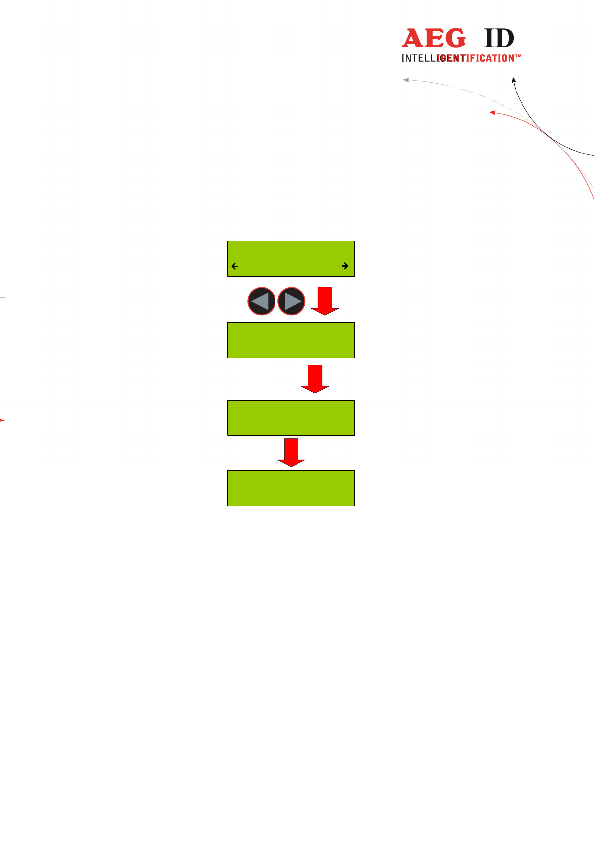
5.13 Set Time (available only with Real-Time-Clock module expansion)
This menu option sets the time of the optional Real-Time-Clock module expansion. With this
expansion module it is possibly to add a time and date code, of reading, to the transponder ID in
the database. The Real-Time Clock module is equipped with a own backup-battery to hold the
time and date even if the ARE H9 is switched off or the main battery of the ARE H9 has to be
changed.
To set the time press select this option with the main button, now is it possible to change the
hours with the left/right arrow button. The hour setting is accepted by pressing the main button;
the ARE H9 switches now the minute setting. The minute and second setting is working in the
same way as the hour setting. After setting the second the Real-Time-Clock will be synchronized
with this new time. To abort the processes during Set Time press the menu button.
Set Time
12:00:00
Set Hour
12 00:00
Set Minute
12 00 00
Set Second
12:00 00
+ 1 h
- 1 h
+ 1 m
- 1 m
+ 1 s
- 1 s
---------------------------------------------------------------26/36-------------------------------------------------------------
5.14 Set Date (available only with Real-Time-Clock module expansion)
This menu option sets the date of the optional Real-Time-Clock module expansion.
To set the date press select this option with the main button, now is it possible to change the day
of month with the left/right arrow button. The day setting is accepted by pressing the main
button; the ARE H9 switches now the month setting. The month and year setting is working in
the same way as the day setting. After setting the second the Real-Time-Clock will be
synchronized with this new date. To abort the processes during Set Date press the menu button.
Set Date
01 Jan '10
Set Day
01 Jan '10
Set Month
01 Jan '10
Set Year
01 Jan 10
+ 1 y
- 1 y
+ 1 m
- 1 m
+ 1 d
- 1 d
---------------------------------------------------------------27/36-------------------------------------------------------------
5.15 Language/Sprache – select display language
With this menu option is it possible to change the language of the ARE H9 menu-display.
Language/Sprache
English
5.16 Reader-Version
This menu option shows the Firmware Revision of the ARE H9.
AEG ID - ARE H9
V3.00136
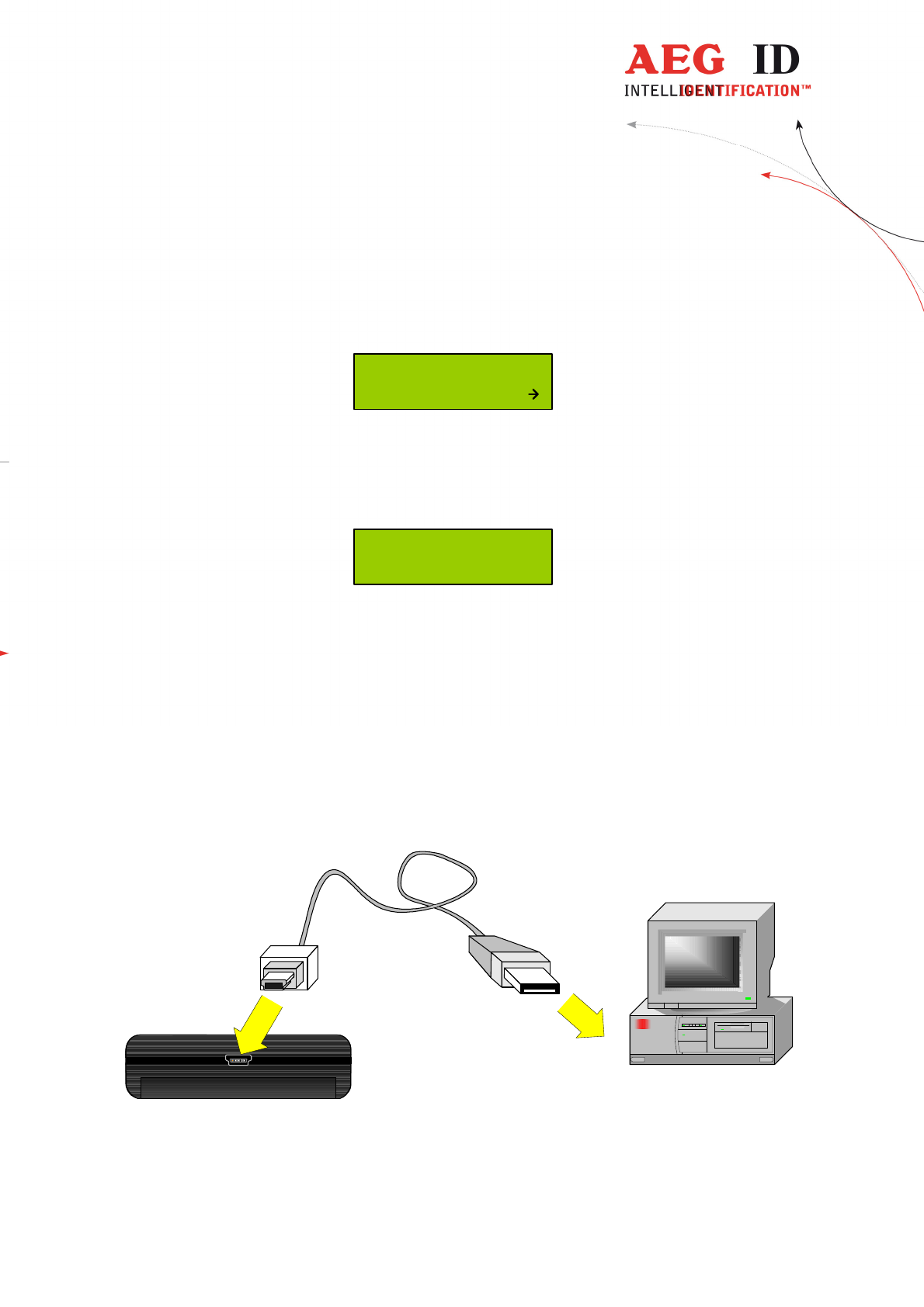
6 USB driver installation *) ***)
To use the online and the database mode the ARE H9 is connected via USB to a host PC.
Before the USB connection could be used a USB to RS232 bridge drive has to be installed.
Insert the driver disc supplied with the ARE H9 into your CD-Rom or DVD-Drive of the host PC
you want to use with the pocket reader. Connect the ARE H9 with the supplied USB cable to a
free USB port of your PC (USB1.1 and USB2.0 ports are supported).
USB connection cable
ARE H9
PC
*) not for Rs232 version
***) forHID Version driver installation is described in the extra documenation
---------------------------------------------------------------28/36-------------------------------------------------------------
USB Device Driver
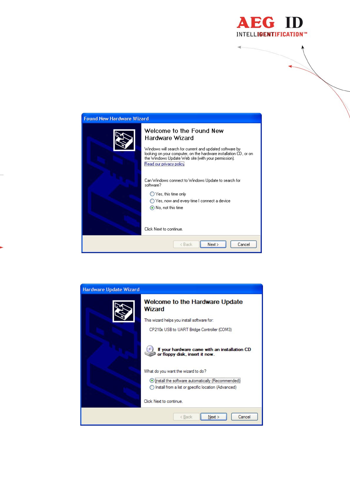
The PC will detect a new hardware; Windows opens the Found New Hardware Wizard.
If the Found New Hardware Wizard asks to connect to Windows Update, select „No, not this
time“, then click „Next“.
---------------------------------------------------------------29/36-------------------------------------------------------------
In the next windows of the Hardware Update Wizard select „
Install from a list or specific location
(Advanced)“.
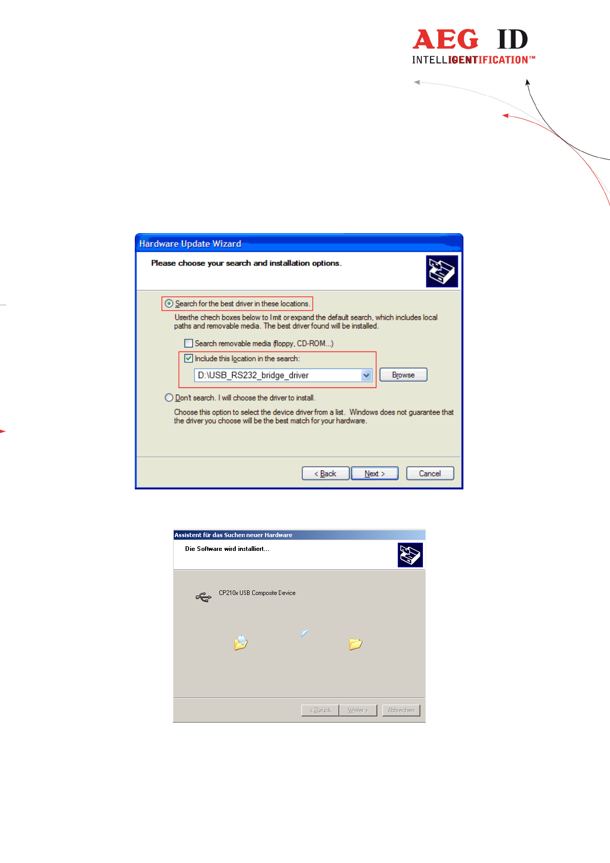
In the search dialog choose „Search for best driver in these locations“. Specify the CP210x driver located in
the CD folder „..\USB_RS232_bridge_driver“.
Click „Next“after setting the path to the driver location
This completes the installation of the USB Device Driver.
---------------------------------------------------------------30/36-------------------------------------------------------------
6.1 Virtual RS232 Com Port
After installing the USB Device Drive Windows automatically starts the installation of the
virtual RS232 Com Port.
Do this installation with the Windows New Hardware Wizard in the same way as with the
USB Device Driver.
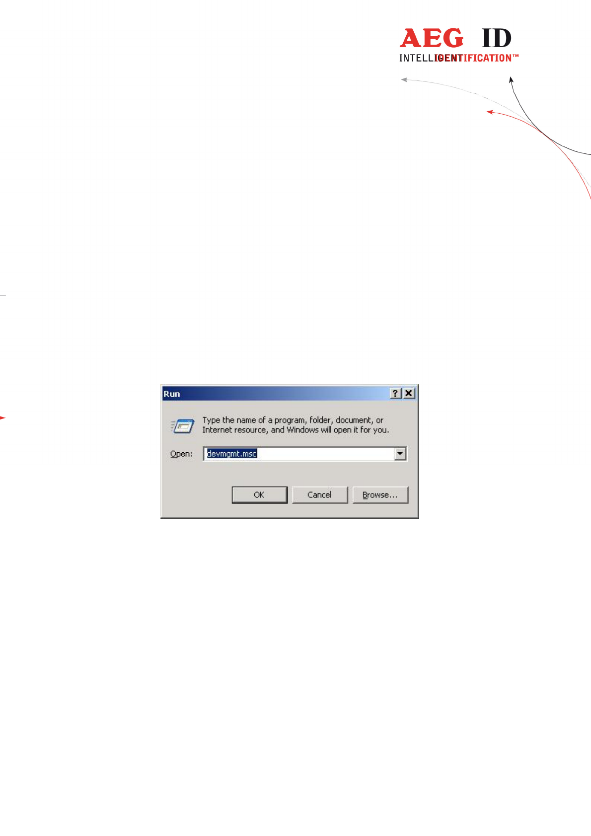
6.2 COM Port Setup with Windows Device Manager
After the installation of the USB Device Driver the COM port setting could be set and verified
by the Windows Device Manager.
Open the Device Manager using start button -> select Run, type in the text field
„devmgmt.msc“and click „OK“.
Another method is to access the Windows Device Manager is: Start -> Control Panel -> System
-> Hardware -> Device Manager.
---------------------------------------------------------------31/36-------------------------------------------------------------
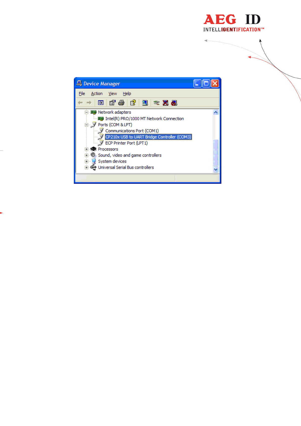
The COM driver for the ARE H9 is located under Port (COM & LPT):
„CP2101 USB to UART Bridge Controller (COMx)“
COMx stands for the COM port selected by the driver, this COM port could used in the software
to communicate with the ARE H9.
In case there is a COM port conflict or another port number is needed, the COM port number
has to be changed.
---------------------------------------------------------------32/36-------------------------------------------------------------
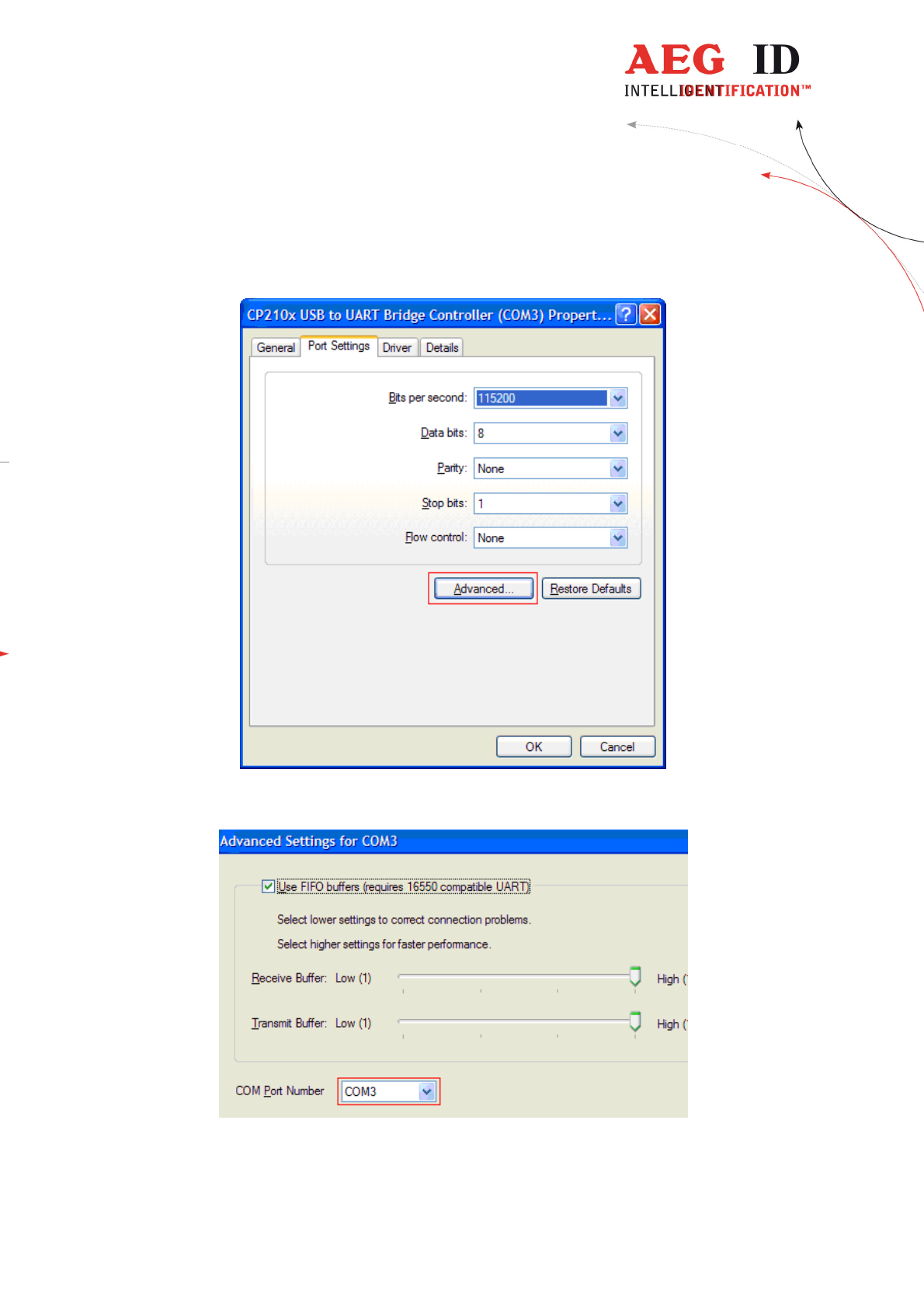
To change the COM port, double click on „Ports (COM & LPT) - CP210x USB to UART
Bridge Controller “.The Properties dialog will open.
Select the „Port Settings“ tab and click on the „Advanced“ button.
Select under „COM Port Number“ the port number to use, then clock „OK“.
---------------------------------------------------------------33/36-------------------------------------------------------------
7 USB Interface Configuration used in online and
database mode
The USB connection to the ARE H9 is established as an additional com port via a USB bridge
driver on the host PC. The protocol uses the RS232 specification with the settings:
19200 Baud, 8 Data bits, no party bit, one stop bit, no hardware handshake.
8 RS232 Interface Settings **)
If the ARE H9 Rs232 is used on a PC a Rs232-Crossover (lines Rxd, Txd are crossed) is
necessary.
In Operation Mode “Database/Ser.” and “online” are the following communication settings in
use:
9600 Baud, 8 Data bits, no party bit, one stop bit, no hardware handshake.
9 Control Characters used in the online mode
character
value
hexadecimal
F
unction
<NL> 0x00 zero character, terminates text element
<STX> 0x02 start of text
<CR> 0x0D carriage return
<LF> 0x0A line feed
**) only in Rs232 version
---------------------------------------------------------------34/36-------------------------------------------------------------
10 Technical Specifications
electrical characterristic
reading system ISO FDX-B, ISO-HDX, Trovan, PSK1, ASK64Bit
operational frequency 134,2 kHz
display LCD: 2-line by 16 charcaters
interface USB
user memory 2016 Codes with attribute, type, text, with optional real time
clock date and time
software AEG ID Terminal PC-Software
power supply 9V alkaline battery Typ 6LR61
environment
storage temperature -10°C up to +70°C
operation temperature 0°C up to +55°C
housing protection IP 50
D
imensions
weight 185 g
length 135 mm
width 70 mm
height 24 mm
material ABS
11 Operation with other RF ID Equipment
As there may be electromagnetic interference between different readers, this reader shall not be
operated within a distance of 3m from any other RFID reader. Otherwise a proper reading result
cannot be guaranteed.

---------------------------------------------------------------35/36-------------------------------------------------------------
12 Safety Instruction
The manufacturer can not be held liable for damages caused by improper use or abuse, lack of
reasonable care, or manipulations contrary to the recommendations given in this manual.
Do not open the reader! There are several spots inside the device, where high voltage is
generated during the scanning process.
The ARE H9 Reader does not contain any parts to be repaired by the user. Any attempt to open
the reader may damage the device. Therefore it may be repaired only by authorized personal.
Environmental conditions, as given in section 10, have to be observed during storage and
operation.
Protect the USB interface socket against dirt, moisture and dust.
For cleaning of the reader and cable use a moistened towel. Never use chemical solvents like
e.g. acetone.
Do not submerge the reader in water.
13 FCC Information
Federal Communications Commissions (FCC) Statement
15.21
You are cautioned that changes or modifications not expressly approved by the part responsible
for compliance could void the user’s authority to operate the equipment.
15.105(b)
This equipment has been tested and found to comply with the limits for a Class B digital device,
pursuant to part 15 of the FCC rules. These limits are designed to provide reasonable protection
against harmful interference in a residential installation. This equipment generates, uses and can
radiate radio frequency energy and, if not installed and used in accordance with the instructions,
may cause harmful interference to radio communications. However, there is no guarantee that
interference will not occur in a particular installation. If this equipment does cause harmful
interference to radio or television reception, which can be determined by turning the equipment
off and on, the user is encouraged to try to correct the interference by one or more of the
following measures:
- Reorient or relocate the receiving antenna.
- Increase the separation between the equipment and receiver.
- Connect the equipment into an outlet on a circuit different from that to which the receiver is
connected.
- Consult the dealer or an experienced radio/TV technician for help.
---------------------------------------------------------------36/36-------------------------------------------------------------
14 Notification of changes
revision
date
description of changes
Editor
001 16.02.2010
first revision HL
002 07.04.2010
Bluetooth option added
Some corrections
HL
003 21.08.2012
Addition for Serial Version HL
004 10.09.2012
Rs232-Configuration added HL
005 17.10.2012
index added HL
006 9.12.2015 Reader Terminal MM
007 19.05.2016
FCC Information MK
008 17.06.2016
FCC Information correction MK
15 Contacts
To improve our products, as well as its documentation is our permanent effort.
For any questions, feedback or comments please call:
Tel.: ++49 (0)731-140088-0
Fax: ++49 (0)731-140088-9000
e-mail: sales@aegid.de
http:\ www.aegid.de