AEG Identifikationssysteme AREK1-1 RFID Reader User Manual ARE K1 Hardware Manual english 10

AEG Identifikationssysteme GmbH RFID Reader ARE K1 Hardware Manual english 10
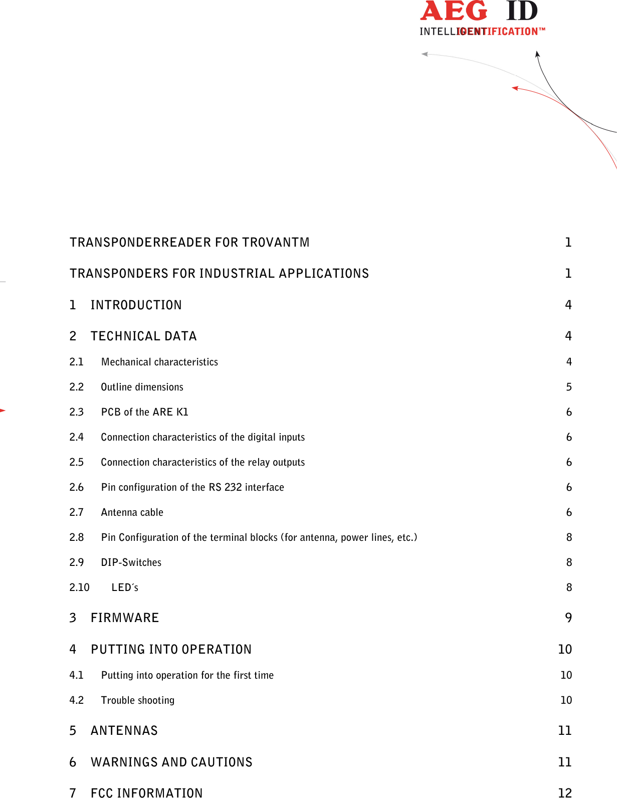
Contents

User manual II

          ARE K1 / RS232ARE K1 / RS232ARE K1 / RS232ARE K1 / RS232    Transponderreader for trovanTM  transponders for Industrial Applications
                 --------------------------------------------------------------------------------2/13--------------------------------------------------------------------------------            TRANSPONDERREADER FOR TROVANTM  1 TRANSPONDERS FOR INDUSTRIAL APPLICATIONS  1 1 INTRODUCTION  4 2 TECHNICAL DATA  4 2.1 Mechanical characteristics  4 2.2 Outline dimensions  5 2.3 PCB of the ARE K1  6 2.4 Connection characteristics of the digital inputs  6 2.5 Connection characteristics of the relay outputs  6 2.6 Pin configuration of the RS 232 interface  6 2.7 Antenna cable  6 2.8 Pin Configuration of the terminal blocks (for antenna, power lines, etc.)  8 2.9 DIP-Switches  8 2.10 LED´s  8 3 FIRMWARE  9 4 PUTTING INTO OPERATION  10 4.1 Putting into operation for the first time  10 4.2 Trouble shooting  10 5 ANTENNAS  11 6 WARNINGS AND CAUTIONS  11 7 FCC INFORMATION  12
                 --------------------------------------------------------------------------------3/13--------------------------------------------------------------------------------  8 NOTIFICATION OF CHANGES  13
                 --------------------------------------------------------------------------------4/13--------------------------------------------------------------------------------   1 Introduction  The reader is designed to read trovantm transponders. It is a robust device for industrial applications. It is es-pecially suited for large reading ranges. The adaption to the individual needs can be performed by selection of the most optimal antenna.  The wide range of applications for this device includes for example: Production control in car assembly and paint shop, barrel logistics, bin identification, skilift management, etc.  Typical reading range is between 20 cm to 70 cm depending on the type of antenna and transponder.  2 Technical data 2.1 Mechanical characteristics  The scanner is integrated into a alloy housing with PG threads for the cable connection. When assembled cor-rectly the housing is good for wet environment according to IP 65. The cable connection is done at the inside of the housing with help of the terminal blocks.  The dimensions of the housing are      220  x  122  x  80 mm The weight is approximately       1,8 kg Storage and operation temperature:     -20° till  +70°C Humidity;             95%   at   +50°C (not condensing)              70%   at   +70°C (not condensing)
                 --------------------------------------------------------------------------------5/13--------------------------------------------------------------------------------   2.2 Outline dimensions
                 --------------------------------------------------------------------------------6/13--------------------------------------------------------------------------------   2.3 PCB of the ARE K1  Input power:  24 V(18....30V) Average input current (active antenna AAN FK2 included):  1 A max Stanby input current (antenna not active)  0,07 A PC interface:  2 wire RS 232 Fuse:  1,6 A/250 V inert Number of Inputs (galvanic disconnected):  1 Number of Outputs:  2 Reading time:  50ms using default settings Reading error rate1:  <1ppm 2.4 Connection characteristics of the digital inputs  The reader is equipped with an galvanic disconnected digital input. The positive edge causes a trigger signal. The input voltage is 24 V.  2.5 Connection characteristics of the relay outputs  Relay  24 V/1 A/1  change over switch The switch conditions can be modified by software parameters. 2.6 Pin configuration of the RS 232 interface  Using the 9 pin Sub-D connector (i.e. for PC) make the following connections: • pin 1 of X3 with housing of sub-D connector (shielding) • pin 2 of X3 with pin 5 of sub-D connector (ground) • pin 3 of X3 with pin 2 of sub-D connector (transmitter line of the reader) • pin 4 of X3 with pin 3 of sub-D connector (receiver line of the reader) Interface parameters: 19200 baud, 8N1 2.7 Antenna cable cable type: see chapter. Maximum recommended cable length between antenna and reader box:  5m.  Other cable length are available on enquiry.                                                      1 definiton of the reading error rate: The reader is set to the default values (i.e. NRD1, NID1, TOR5, MD2...). A transponder is located stationarily within the  optimal antenna field (signal level is at least 250mV above noise level). The reader is triggered 1,000,000 times using the GT command. The total number of wrong readings is zero.
                 --------------------------------------------------------------------------------7/13--------------------------------------------------------------------------------                           pin configuration of the PCB  X1X2X3X4X5shieldinggroundTXDRXD123456make contact of relay QN112345datashielding of datasyncground12Vbreak contact of relayQN1121224VgroundLED1 - antennaLED2 - no readLED3 - readLED4 - dig-inputLED5 - errorLED6 - powerLED7 - RxDLED8 - TxDLED9 - not usedrelay QN1make contact of relay QR1relay QR1break contact of relayQR1digital input  +digital inputOn12345678DIP-SwitchTP4JP5JP1JP2JP3JP4+12V GND3412
                 --------------------------------------------------------------------------------8/13--------------------------------------------------------------------------------  2.8 Pin Configuration of the terminal blocks (for antenna, power lines, etc.)  a) using LiY-LiYCY-Y 2+2x0,5 (delivered until march 2001) b) using Li2YCY (TP) 3x2x0,34 (delivered from march 2001)               2.9 DIP-Switches         In normal condion (ex work) all DIP-switches are set OFF (down).  If switch 1 is in position ON, the default values (see chapter 3 - firmware) are loaded out of the EPROM at a cold start (when reader is put in operation). DIP-switches 2 ... 8 have no function. 2.10 LED´s  There are several LED’s inside of the reader housing on the PCB. The functions of these LED’s are: LED 1 on when antenna is operated. LED 2 on when last read was not successful. LED 3 on when last read was a success. LED 4 on as long as the digital input is high. LED 5 on when a hardware error was detected. LED 6 flashing as long as the reader is powered and the microprocessor is working properly. LED 7 on as long as commands were received on the RS 232 interface. LED 8 on as long as information is transmitted from the RS.232 interface. On1 2 3 4 5 6 7 8DIP-SwitchX1 - readerantennaconnector12345DataSchirmSyncGND12V1264whiteshield of whitebrowngreen3shield of brown5yellowX1-readerantennaconnector12345datashieldsyncGND12V126435whitegreygreenyellowbrownpinkshield
                 --------------------------------------------------------------------------------9/13--------------------------------------------------------------------------------   3 Firmware  The reader supports ASB (AEG ID standard set of instructions). When delivered the reader´s configuration is set into the operation mode 2 (readings triggered by serial interface). The reader can be set to the operation mode 0 (continuous operation) or to the operation mode 1 (triggered by external input). The parameters NRD and NID should only be changed after consulting the manufacturer.   The following commands are supported by the reader  command-code function  action on interface  Compability with ASB1.0 DIAG diagnosis / state of the reader state or error message no GT read transponder (get tag) transponder number yes INIT load basic configuration boot message / <CR> yes RST warm start boot message / <CR> yes VER Output version number version number yes VS Output of all parameter values List of parameters yes VSAVE store current configuration ok yes  The parameters which can be modified are:  com-mand-code function  universally defined pa-rameters (ASB 1.0) valid parame-ter values for ARE K1 default-values MD  mode of operation  0 .. 2  0 .. 2  2 (triggered by     interface) BD baud rate 0 .. 3 0 .. 3 2  (19200baud) EC echo 0, 1 0, 1 0  (off) CN suppression of NoRead 0, 1 0 .. 2   0  (output FFFFFFFFFF) CID  filter function for multiply read IDs 0, 1  0, 1  0 (filter off) NID  number of identical IDs per read-ing cycle 0 , 1  0 , 1  1 (two out of two) NRD superimposition of telegrams 0 .. 2 0 .. 2 1 (two telegrams) QN1  digital output QN1  0 .. 2  0 .. 2  2  (controlled by reading process) QR1  digital output QR1  0 .. 2  0 .. 2  2  (controlled by reading process) TOR  timeout parameter for unsuccess-full reading 0...9  0...255  5  (500ms) ALGO algorithm (type of transponder) - 0 .. 2 1 (trovan read only) PM type of protocol - 0, 1 0 (ASCII-protocol)  For more details please see the manual „Command Set for ARE K1“.
                 --------------------------------------------------------------------------------10/13--------------------------------------------------------------------------------  4 Putting into operation 4.1 Putting into operation for the first time a)  Connect the device to a 24 V DC source which is able to provide a minimum of 1 A. Connect the antenna with the device. Connect a Personal Computer or equivalent to the device via the RS 232 interface. Please assure the interface is set to the right baud rate.  b)  Establish a connection to the reader (parameter: 19200 baud, 8N1) by using an appropriate software (for ex-ample Windows terminal program). Test the configuration of the reader with the command VS.  c) If the device is in operating mode 2, each reading has to be startet using the GT command transmitted on the serial interface. If the device is in operating mode 0, the scanner will send transponder numbers to the comput-er, as long as a tranponder is in the active antenna field.  d)  After the device is successfully tested as described above, you can set the reader configuration as needed. De-tails how to change the configuration of the scanner are described in the ASB description. 4.2 Trouble shooting  Should the reader not work as desired, please check the following:  a)  Is the configuration of the reader as wanted? Check with help of the command VS! b) Is the configuration not known, the baud rates of reader and terminal set different? Restore the basic setting of the parameters values as follows! Put DIP-switch 1 ON, make a cold start by interrupting the power supply, put DIP-switch 1 OFF again. Now all paramter values are set to the default values, the reader will work in normal condition. Attention! All set-tings are temporary. This means they are lost after switching of the reader. Make the setting permanent using the command VSAVE. c)  Is the antenna defect or not properly connected? (In that case LED 2 is not on although the reader is in read mode) d)  The transponder is not in the active antenna field. Bring the transponder closer to the antenna. e) Antenna mounting is wrong (for example on a metal plate). In such a case, it can happen that the radiated antenna power is consumed by eddy currents in nearby metal structures. An indication for such situation is an exceptional high current consumption of the reader. Noise can also reduce the read range.  f)  High frequency fields radiated by other devices interfere with the reader communication. Please check if such devices are near to the antenna or the antenna cables. Typical devices which interfere on the reading range are for example: some monitors for computers, switched power supplies, electrical motors, etc. Please remove such devices or remove the radiated interferring filed by proper grounding. g)  If the mechanical configuration of metal pieceparts can not be changed and or not suitable for proper read-ings. Please check, if with a different antenna better reading results can be obtained. Also electrical insulation for metal parts against each other can help to reduce the eddy current effect. f) If the noise resistance or reading frequency of the reader was reduced by changing the parameters NID or NRD, please return the reader to the preset configuration of the manufacturer. g) LED5 is on indicating an hardware failure. If a reset after checking all above points does not help return the device for repair.
                 --------------------------------------------------------------------------------11/13--------------------------------------------------------------------------------  5 Antennas  The following antennas are suitable for this reader:  a) high power plate antenna  AAN  FK6 (only choice for USA) b) high power plate antenna  AAN  FK2 / FK3 c) rod antenna    AAN  FK0  The reader with above antennas was tested against the requirements according ETS 300683 and EN 55022 class B. It is possible that antennas of other manufacturers may fit to the device. However, if connecting such non orig-inal manufacturer antennas to the device, the warranty will get lost. Also a separate operation permission by the local state administration might be required.        Special models  The standard device is equipped with an RS 232 interface. On request there are special models available which support the interface with one of the following interfaces instead of the RS 232: -  Modbus + -  Interbus S - Profibus DP -  CAN -  RS485   6 Warnings and cautions  Υ    When using the original AEG ID antennas suited for that device, the combination of antenna and reader have the German permission for operation. Please check, if special permissions are required at the place of opera-tion. Υ    This reader is an active electrical transmission system and radiates in the frequency range of approximately 124 kHz. When connecting a defect or a not suited antenna to the device the radiated power can be higher than 42dBµA/m (measured at 10 m distance). The operator is responsible that people at risk are not end-agered by the device. Υ    Do not operate the device with open housing, as otherwise there is a danger, that positions with dangerous volt-age can be touched. Υ Never operate the device with defect antenna cables. The antenna cables may conduct dangerous voltages. When disconnecting an antenna cable please assure that the device is turned off and the cable was groundes for a short time before touching it. Otherwise stored energy of the antenna may cause harm.  Υ   The device should only be opened by trained personal when switched off.  ΥΥΥΥ    Caution!  ΥΥΥΥ          Never mount or place the antenna on extended metal parts. Do not bring another antenna very near at the operated antenna (second antenna operated or not). In both cases there is a risk, that the antenna may be destroyed. Such defects are not covered by the warranty.
                 --------------------------------------------------------------------------------12/13--------------------------------------------------------------------------------  7 FCC Information Federal Communications Commissions (FCC) Statement 15.21 You are cautioned that changes or modifications not expressly approved by the part responsible for compliance could void the user’s authority to operate the equipment. 15.105(a) This equipment has been tested and found to comply with the limits for a Class A digital de-vice, pursuant to Part 15 of the FCC Rules. These limits are designed to provide reasonable protection against harmful interference when the equipment is operated in a commercial environment. This equipment generates, uses, and can radiate radio fre-quency energy and, if not installed and used in accordance with the instruction manual, may cause harmful interfer-ence to radio communications. Operation of this equipment in a residential area is likely to cause harmful interfer-ence in which case the user will be required to correct the interference at his own expense.
                 --------------------------------------------------------------------------------13/13--------------------------------------------------------------------------------   Copying of this document and giving it to others and the use or communication of the contents thereof, are forbidden without  express authority. Offender are liable to the payment of damages. All rights are reserved in the event of the grant of a patent or the registration of a autility modul or design.  AEG Idenfikationssysteme GmbH Hörvelsinger Weg 47 D-89081 Ulm  Tel: 0049-(0)731/140088-0  Fax: 0049-(0)731/140088-9000  e-mail :   sales@aegid.de www.aegid.de   8 notification of changes  change no  date  description of change  version  editor          10/01  08/22.01 • connection of serial interface • operating mode ex work now MD2 • supplemetation: commands ALGO and PM 06    10.08.10 • Format  07     05/18/16 • FCC Information  08     06/22/16 • FCC Information correction  09  MK   10/05/16 • FCC Information correction  10  MK

Navigation menu