AEG Identifikationssysteme AREK1-1 RFID Reader User Manual Installation AAN FK6 engl
AEG Identifikationssysteme GmbH RFID Reader Installation AAN FK6 engl
UserManual.wiki
>
AEG Identifikationssysteme
>
AREK1-1 User Manual
>
user manual ext antenna
Contents
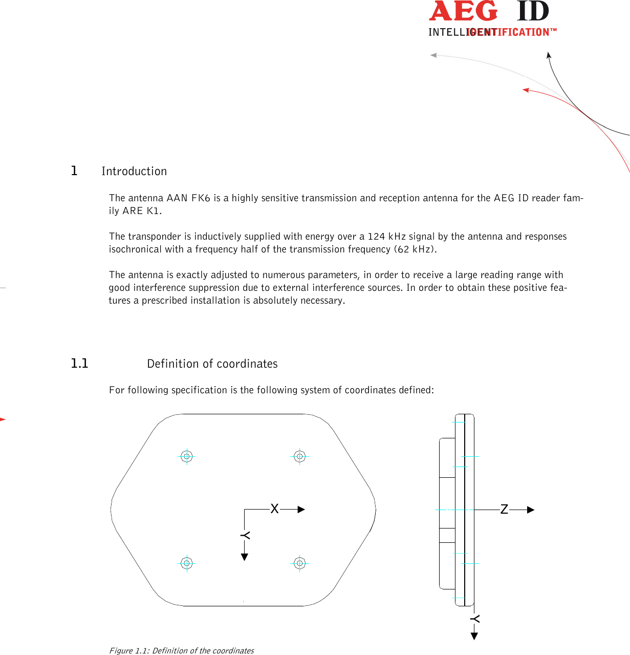
1.
user manual
2.
User manual II
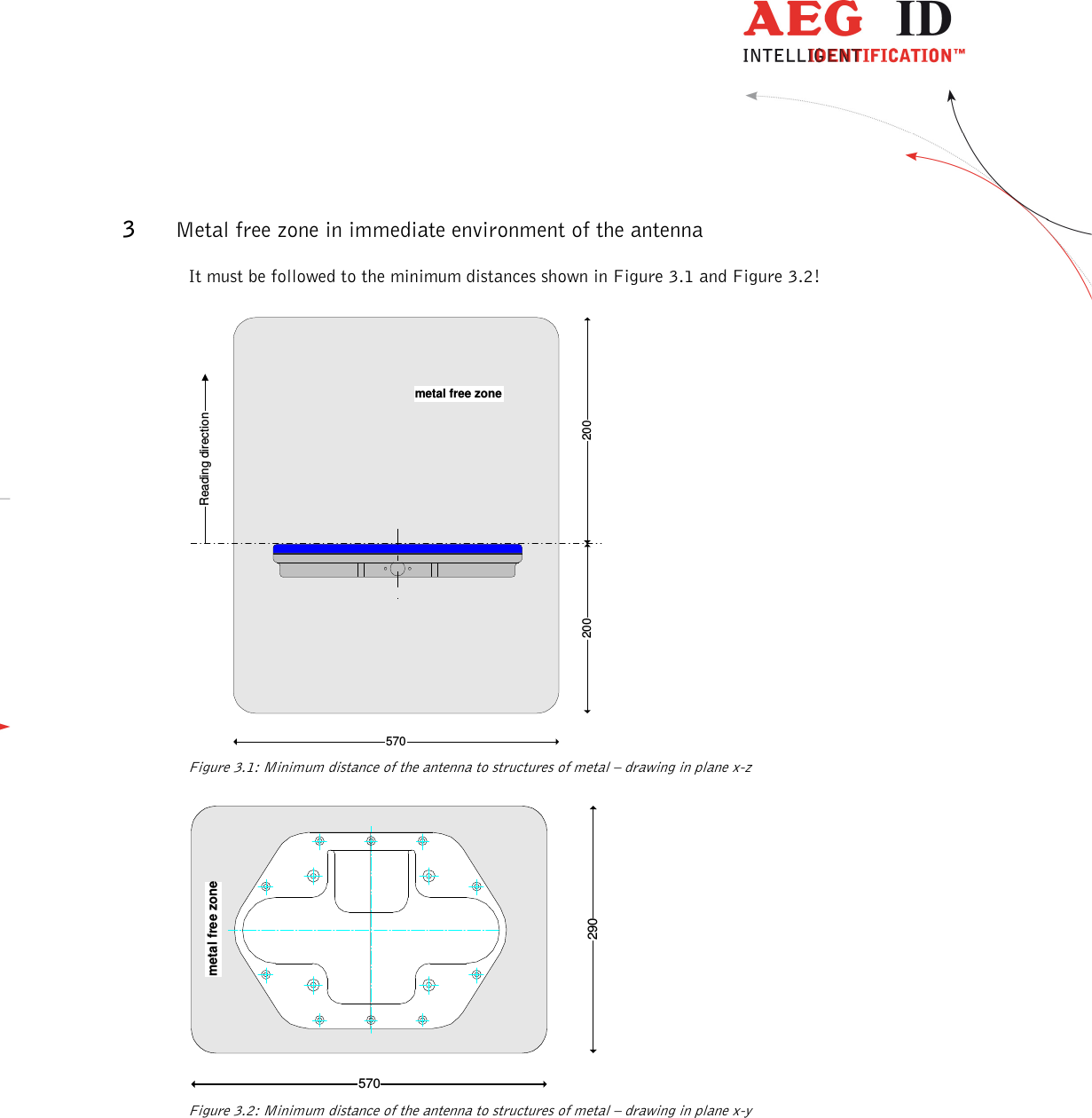
3.
user manual ext antenna
user manual ext antenna
Navigation menu
Upload a User Manual
Namespaces
Wiki Guide
HTML
PDF
Info
Views
User Manual
Discussion / Help
Navigation
![--------------------------------------------------------------------------------3/8-------------------------------------------------------------------------------- 2 Mounting of the antenna non-metallicmounting ground(a)(b)Nut M6Screw M6AntennaAAN FK6AntennaAAN FK6Screw M6 Figure 2.1: Mounting of the antenna at the front (a) and rear (b) The antenna can be fixed at a proper mounting support. The holding down bolts may be tightened maximal-ly with 2 [N/m]. metal Figure 2.2: False handling of the antenna Because of the functional principle it must be taken care that the antenna is not inductively short-circuited by the mounting construction. Especially the direct mounting on a frame or a plate of metal provoke such a short-circuit and can lead to a destruction of the antenna. When mounting on a concrete wall it is to notice that this wall may contain reinforcing iron in an unfavourable geometry. In this case only a power dissipa-tion occurs because of the distance of the iron-structure, but not a complete short-circuit. In this configura-tion the reading range is lower than specified and the current consumption is higher than normal. When operating an antenna in laboratory it must be paid attention that the antenna in operation must not be laid on another antenna. In such a case also an inductively short-circuit takes place which may lead to a destruction of the antenna. Two adjacent antennas should have a distance of at least 50 cm to each other.](https://usermanual.wiki/AEG-Identifikationssysteme/AREK1-1.user-manual-ext-antenna/User-Guide-3156732-Page-3.png)