AEG Identifikationssysteme URH1HL RFID Reader User Manual Manual ARE H9 HF 006
AEG Identifikationssysteme GmbH RFID Reader Manual ARE H9 HF 006
UserManual.wiki
>
AEG Identifikationssysteme
>
URH1HL User Manual
user manual
Navigation menu
Upload a User Manual
Namespaces
Wiki Guide
HTML
PDF
Info
Views
User Manual
Discussion / Help
Navigation
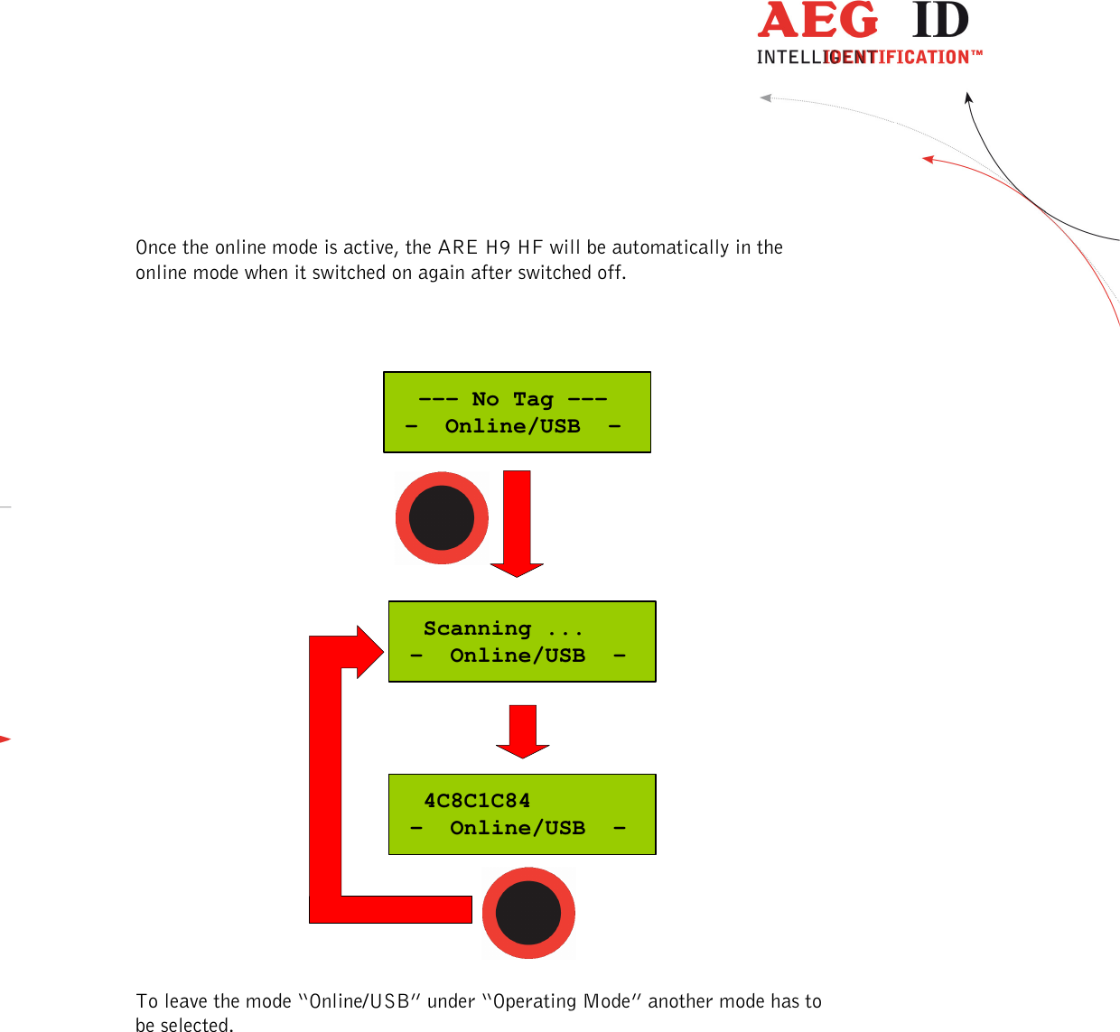
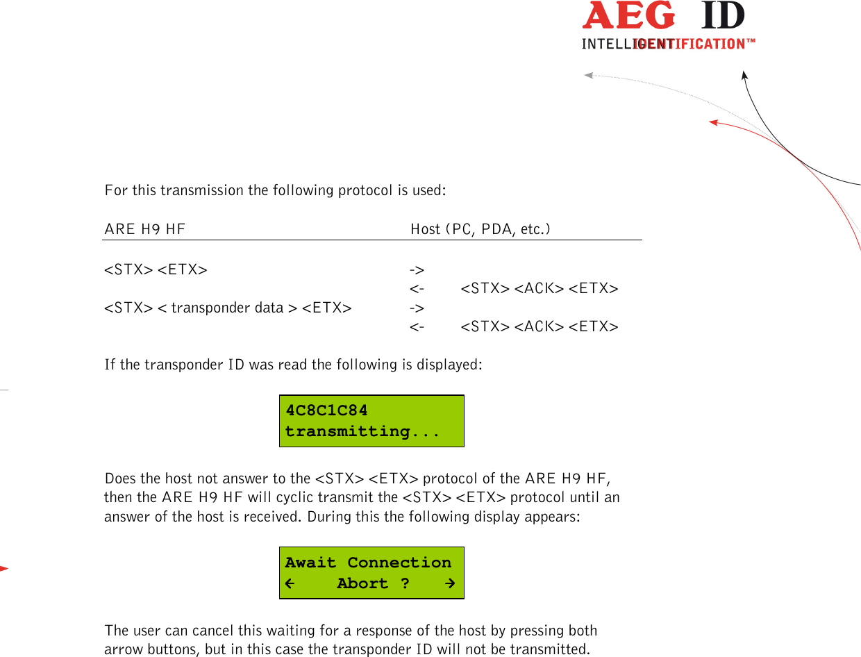
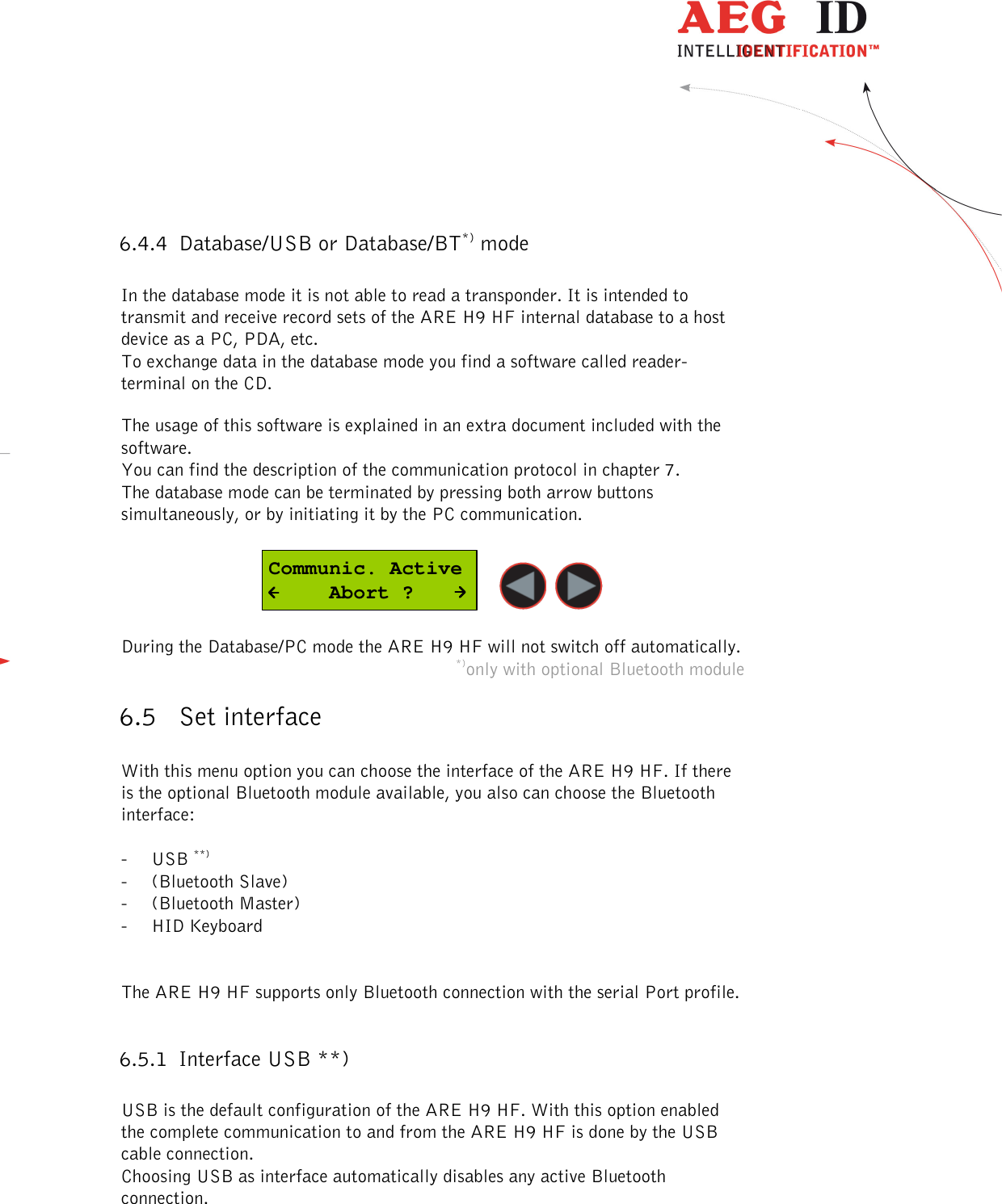
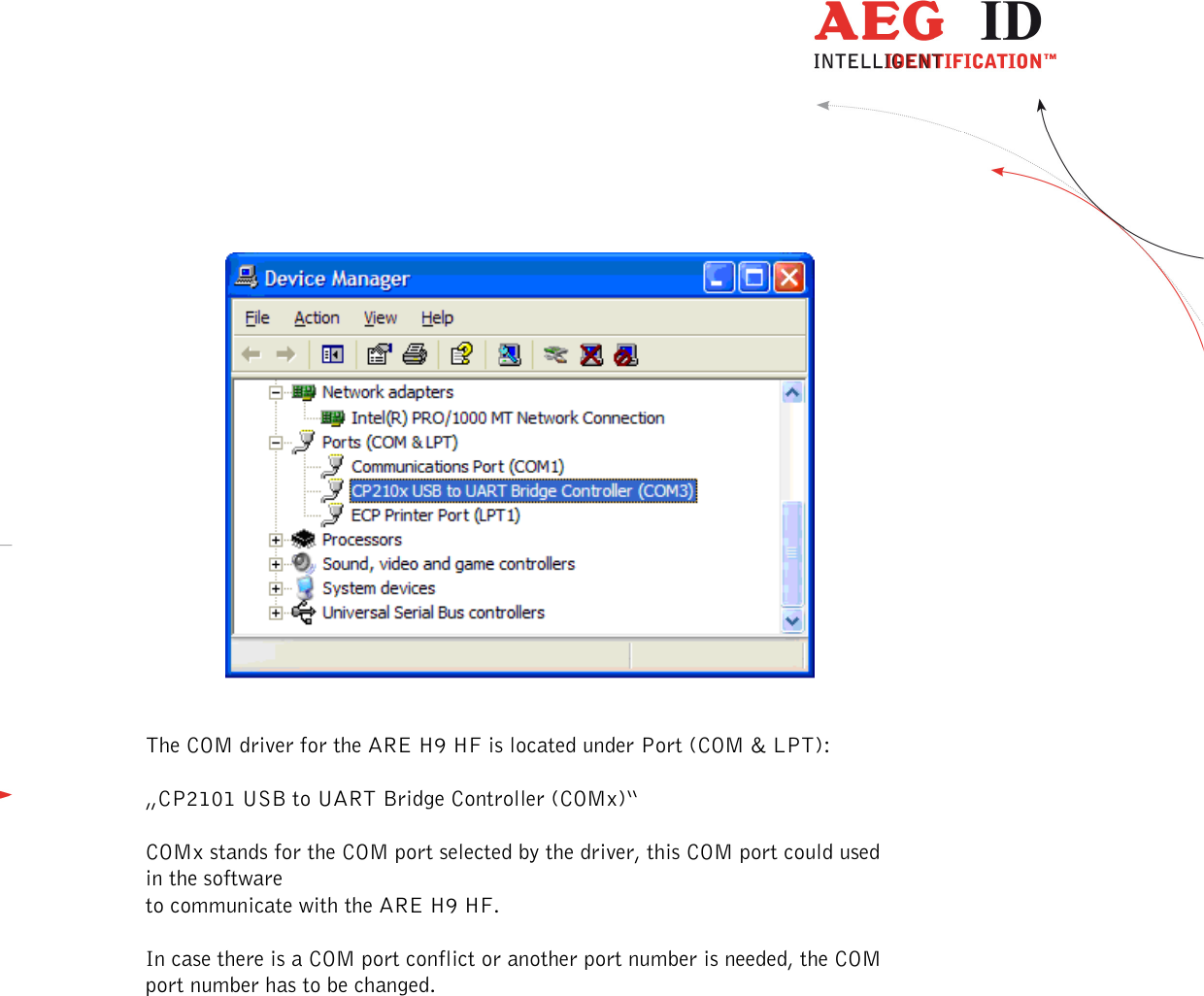
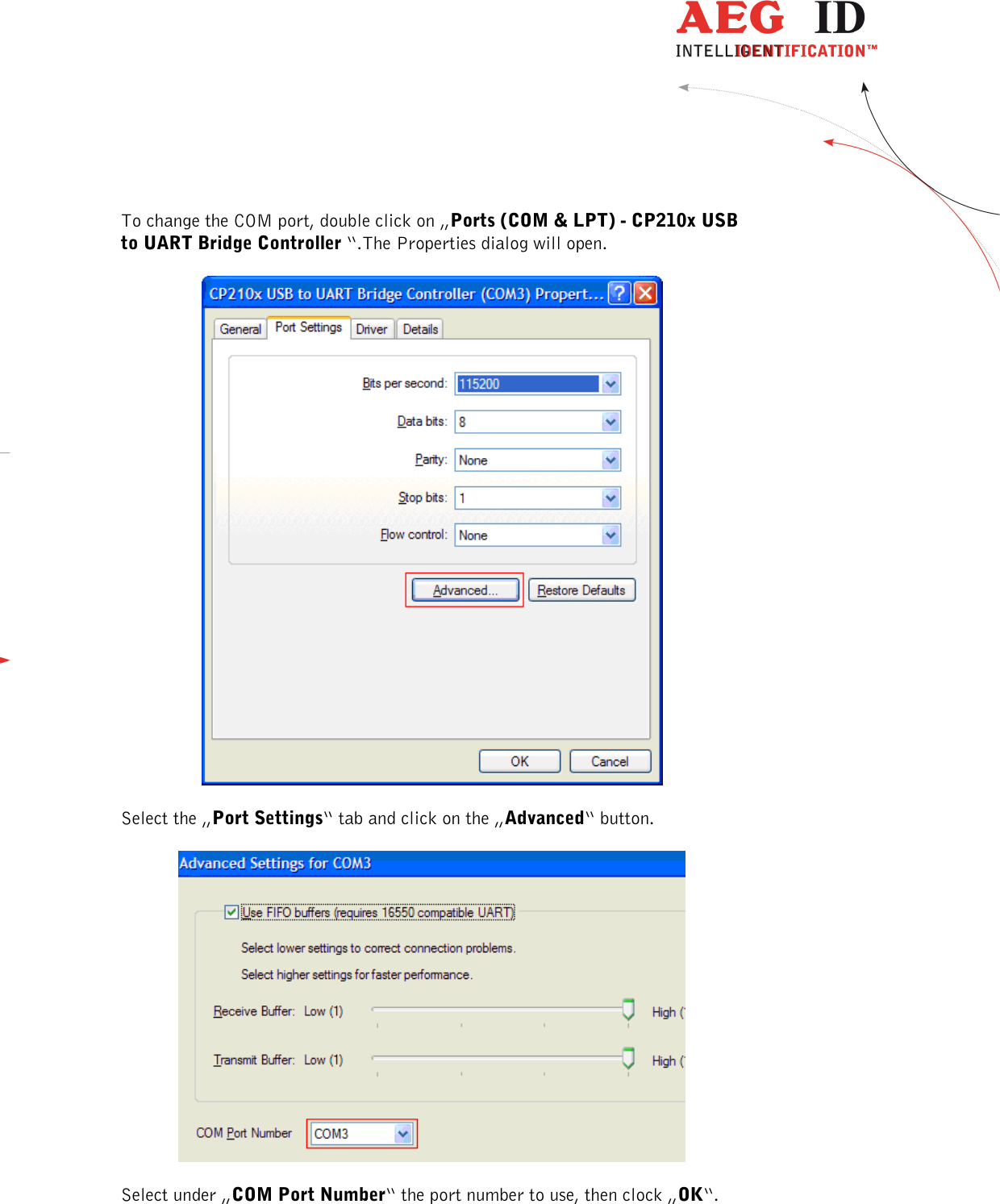
![---------------------------------------------------------------34/51--------------------------------------- Example in ANSI C: The CRC checksum in this software example is implemented as a reverse CRC-CCITT: The check sum is always composed out of 4 hex characters (values from 0x0000 to 0x FFFF). These 4 hex characters are transmitted in ASCII code from '0' .. '9' and 'A' to 'F' . Example: The check sum 0E2A is transmitted as CHR(0x30), CHR(0x45), CHR(0x32), CHR(0x41). // ********************************************************************* // Function to calculate the CRC from a protocol buffer with // the given length // ********************************************************************* unsigned int build_crc(unsigned char length, unsigned char* protocol) { // the initial CRC value #define CRC_PRESET 0x0000 // the reverse CRC-CCIT pollynomial #define CRC_POLYNOM 0x8408 unsigned char i,k; unsigned int crc; unsigned char crc_in; crc CRC_PRESET; // initial value for(i=0;i< length;i++) // loop trough the protocol { crc_in = protocol[i]; // get next protocol byte for (k=0;k<=7;k++) // loop trough one byte LSB to MSB { // test each Bit for CRC calculation if((((crc_in>>k)&0x01)^(crc&0x0001))==1) { crc=crc>>1; crc=crc^0x8408; } else { crc=crc>>1;} } } return(crc); }](https://usermanual.wiki/AEG-Identifikationssysteme/URH1HL/User-Guide-3343793-Page-34.png)