AEG Identifikationssysteme URH1HL RFID Reader User Manual Manual ARE H9 HF 006
AEG Identifikationssysteme GmbH RFID Reader Manual ARE H9 HF 006
user manual
---------------------------------------------------------------1/51------------------------------------------
User Guide
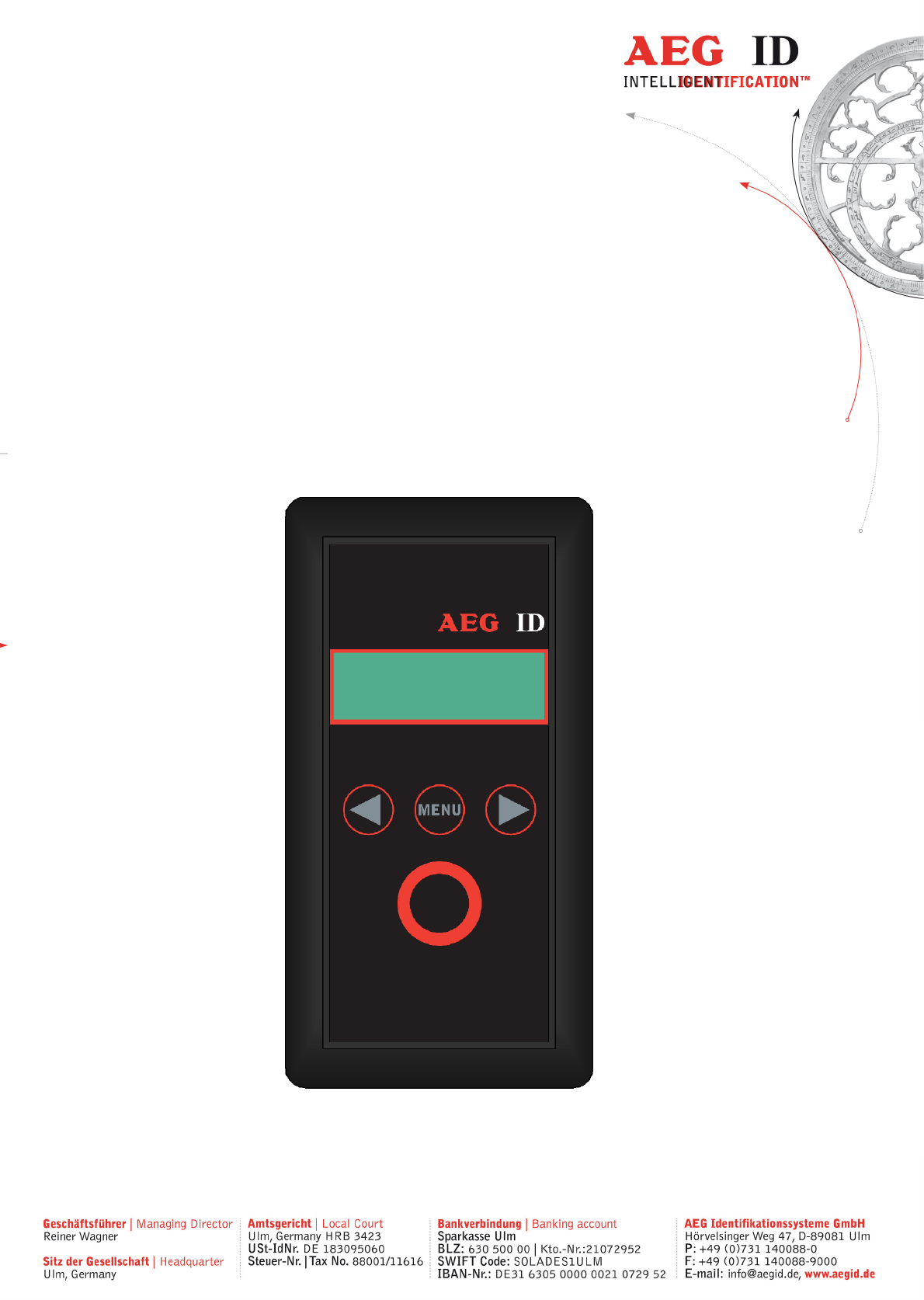
ARE H9 HF
Pocket Reader
ARE H9 HF

---------------------------------------------------------------2/51---------------------------------------
1 INTRODUCTION 4
2 ELEMENTS OF THE ARE H9 HF 5
3 OPERATION GUIDE 6
3.1 Installation of the battery 6
3.2 Power on/off 6
3.3 Reading a transponder in standard mode 7
4 READING RANGE 8
4.1 Orientation with air coil antenna 9
4.2 Orientation with ferrite antenna 10
5 DATABASE 10
6 MENU FUNCTIONS 11
6.1 Navigating trought the menu function 11
6.2 Overview of the menu functions 12
6.3 Set Attribute 13
6.4 Operating Mode 14
6.5 Set interface 19
6.6 Lock up reader 25
6.7 Mirror Code 26
6.8 Erase memory 26
6.9 Reading time 27
6.10 Turn-off time 27
6.11 Turn-on delay 28

---------------------------------------------------------------3/51---------------------------------------
6.12 Keyboard sound 28
6.13 Set time (available only with Real-Time-Clock module expansion) 29
6.14 Set date (available only with Real-Time-Clock module expansion) 30
6.15 Language/Sprache – select display language 31
6.16 Reader version 31
7 DATA EXCHANGE PROTOCOL 31
7.1 Set of commands 31
7.2 Protocol structure 32
7.3 Checksum CRC 33
7.4 Structure of the data base 35
7.5 Simplified read out procedure, without programming the CRC-routine 36
7.6 The command structure in detail 37
7.7 Parameter changing commands 39
7.8 Attributes 41
8 CONTROL CHARACTERS USED IN THE ONLINE MODE 43
9 USB DRIVER INSTALLATION 43
10 TECHNICAL SPECIFICATIONS 49
11 OPERATION WITH OTHER RFID EQUIPMENT 49
12 SAFETY INSTRUCTION 50
13 FCC INFORMATION 50
14 NOTIFICATION OF CHANGES 51
15 CONTACTS 51

---------------------------------------------------------------4/51---------------------------------------
1 Introduction
The ARE H9 HF is a RFID Pocket Reader designed to read passive
transponders.
It has the ability to store the transponder codes in its internal database.
This Pocket Reader is equipped with a USB interface and optional Bluetooth or
RS232 interface, which allows transmitting single transponder codes or its entire
database to a computer.
The ARE H9 HF is capable to read the following transponder types:
• ISO 14443A
• ISO 15693
Before the initial use of this ARE H9 HF reader please study this manual carefully.
---------------------------------------------------------------5/51---------------------------------------
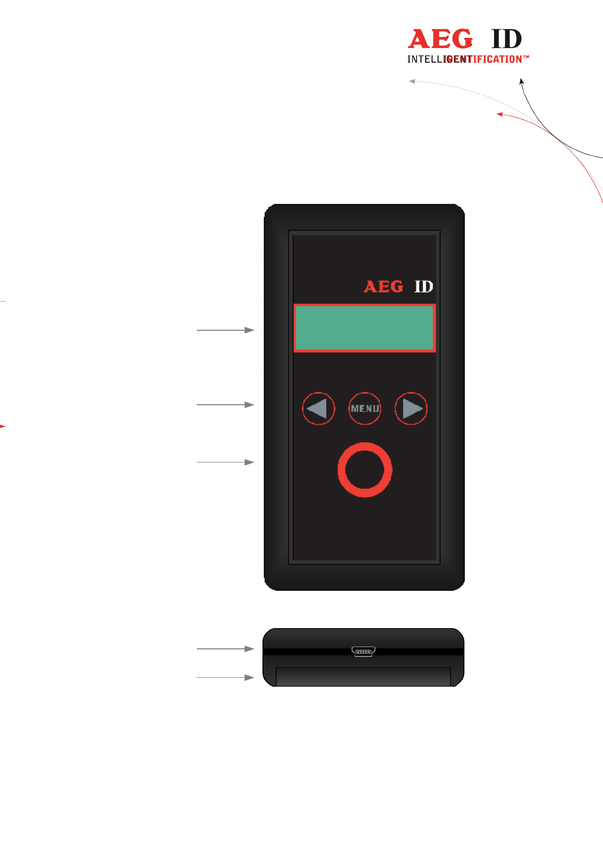
2 Elements of the ARE H9 HF
2x16 Character
LCD-Display
Menu option buttons
(left, menu, right)
USB connector **)
Main button
(read, select)
Battery
compartment
ARE H9 HF
**) RS232 cable in Rs232 version
---------------------------------------------------------------6/51---------------------------------------
3 Operation Guide
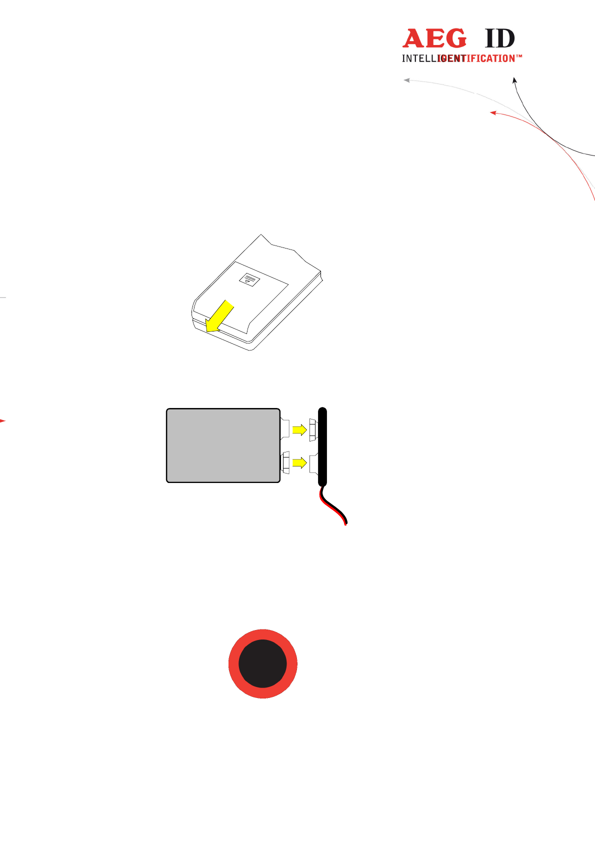
3.1 Installation of the battery
Slide door of the battery compartment to open it.
Attach the Battery to the connector inside. Put the Battery into the
compartment.
9V Block
Battery
Batterieclip
-
+
Slide the door back to close it. Use only 9V E-Block alkaline Batteries of the
Type 6LR61.
3.2 Power on/off
The Pocket Reader is switched on by pressing the main button for 0,5s (default).
The reader starts in reading mode.
The ARE H9 HF will switch off automatically after 20s (default) when no button
has been pressed within this time.
---------------------------------------------------------------7/51---------------------------------------
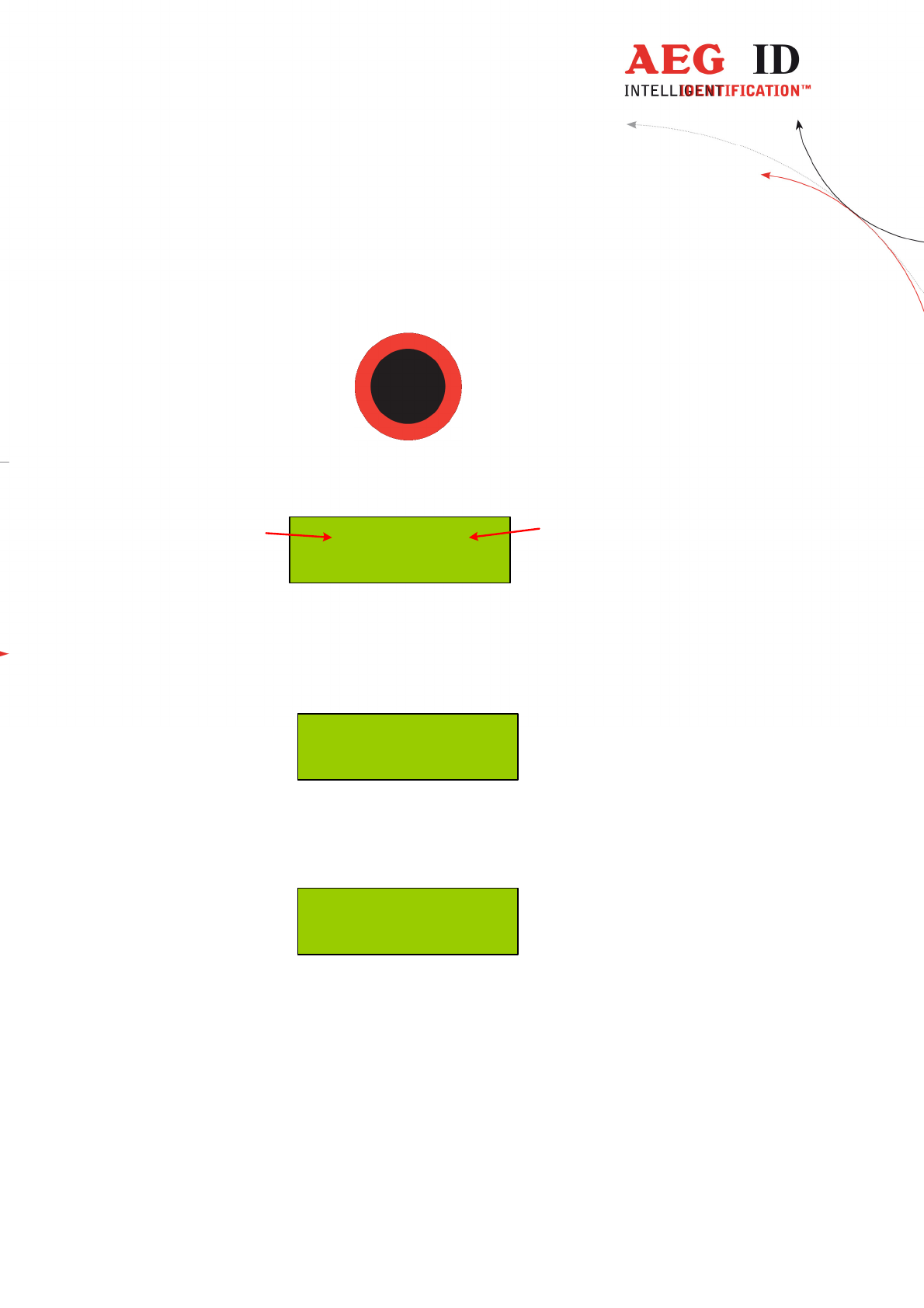
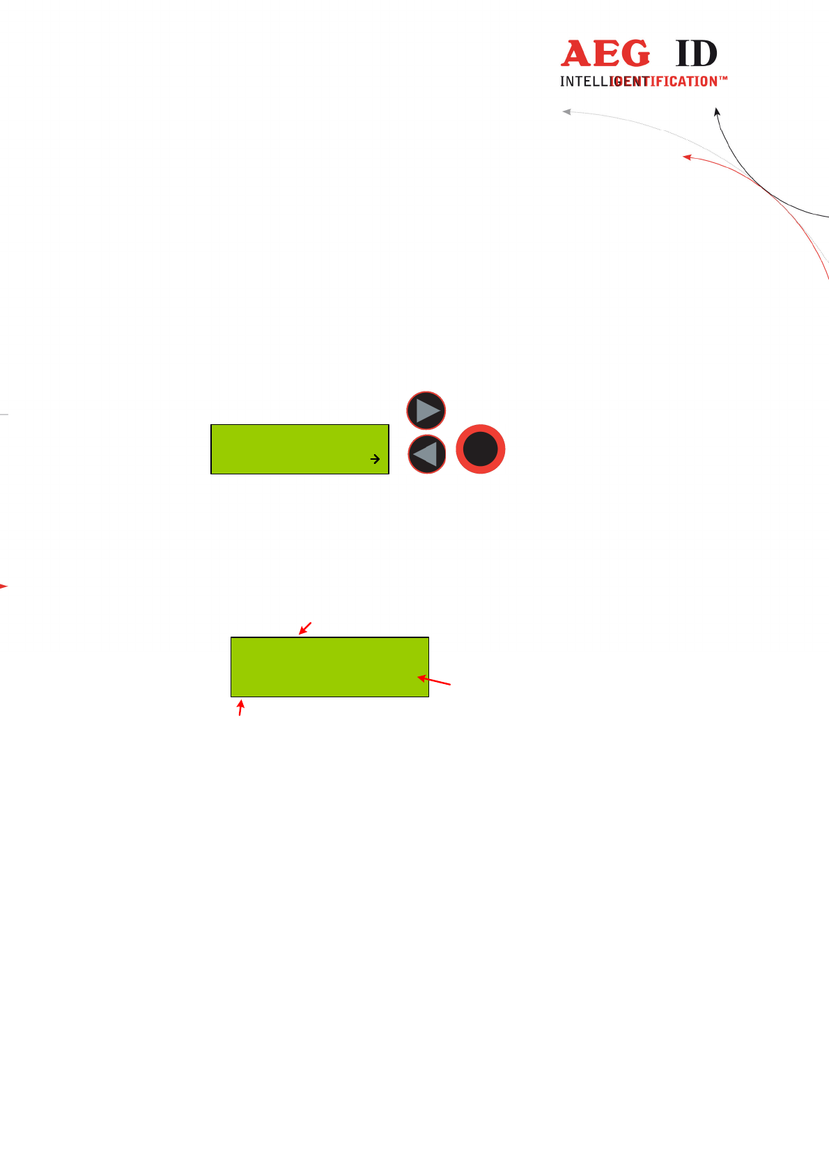
3.3 Reading a transponder in standard mode
Press the main button to start the reading process.
The ARE H9 HF starts the reading process and the display shows:
0 of 2016
Scanning Nr. 1
actual
count
maximum
count
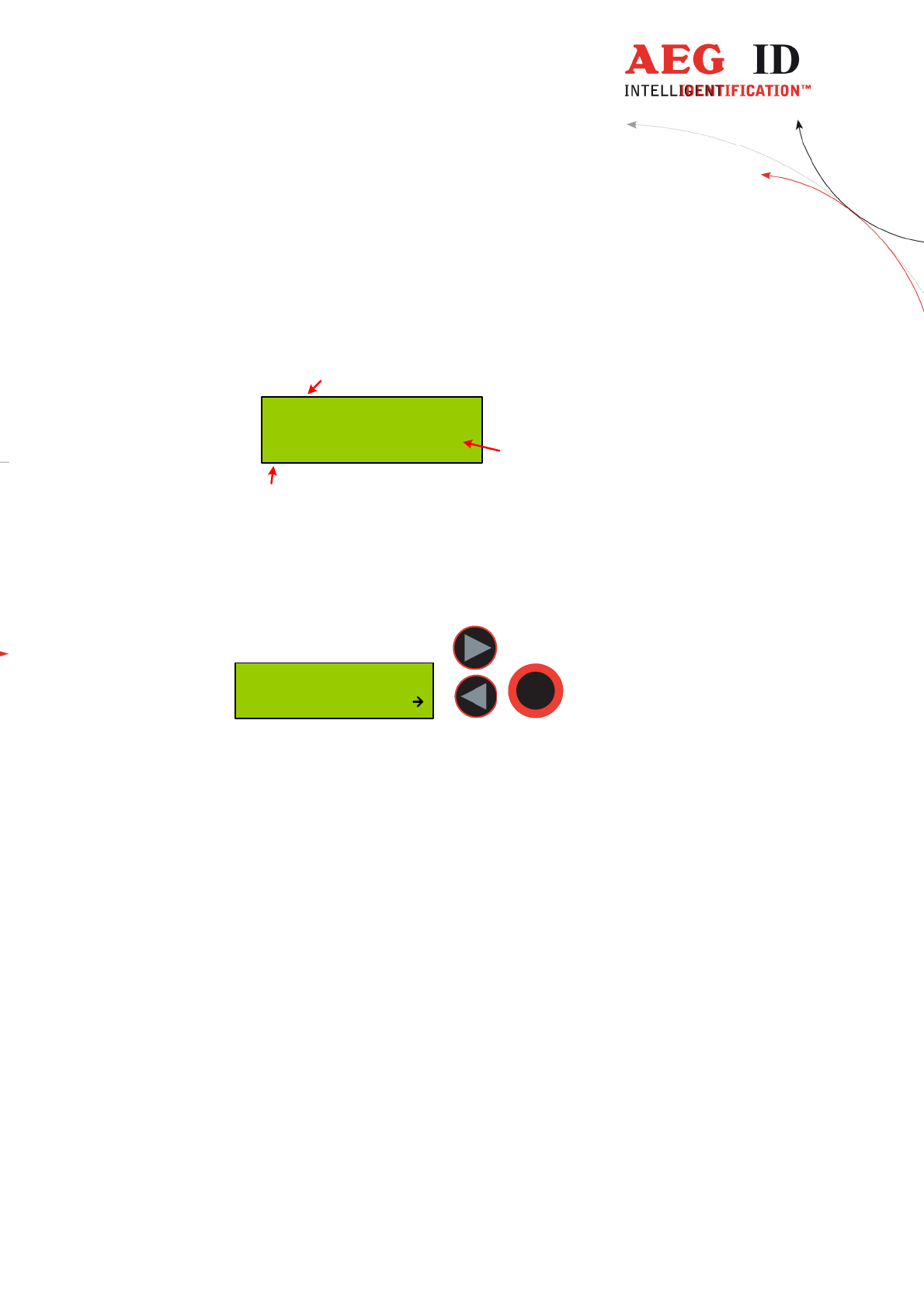
Approach a transponder within the readers reading range.
The reader emits a beep when the transponder has been read successfully, and the
transponder code is shown on the display:
4E779B90
ISO-14443A
In case no transponder has been read within the given time frame, the reader stops
its reading process and the display shows:
--- No Tag ---
For further reading processes release the main button and press it again for each
attempt.

---------------------------------------------------------------8/51---------------------------------------
4 Reading range
The reading range and distance depends on the antenna type of the reading
device, the transponder, its packaging and orientation to the reader. The ARE
H9 HF is available ether with air coil antenna or ferrite antenna.
It is not possible to read two or more transponders at the same time.
---------------------------------------------------------------9/51---------------------------------------
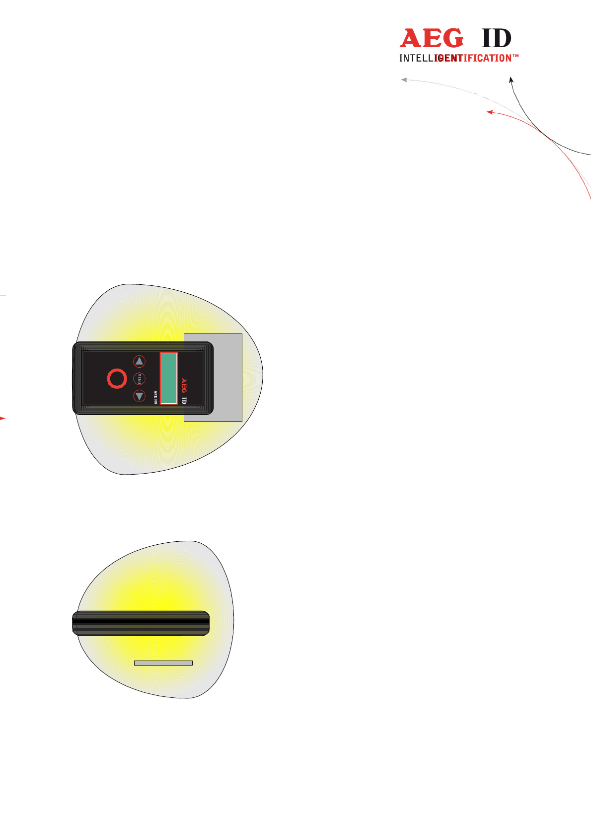
4.1 Orientation with air coil antenna
The following diagram shows the typical area where a card transponder should
be read:
---------------------------------------------------------------10/51---------------------------------------
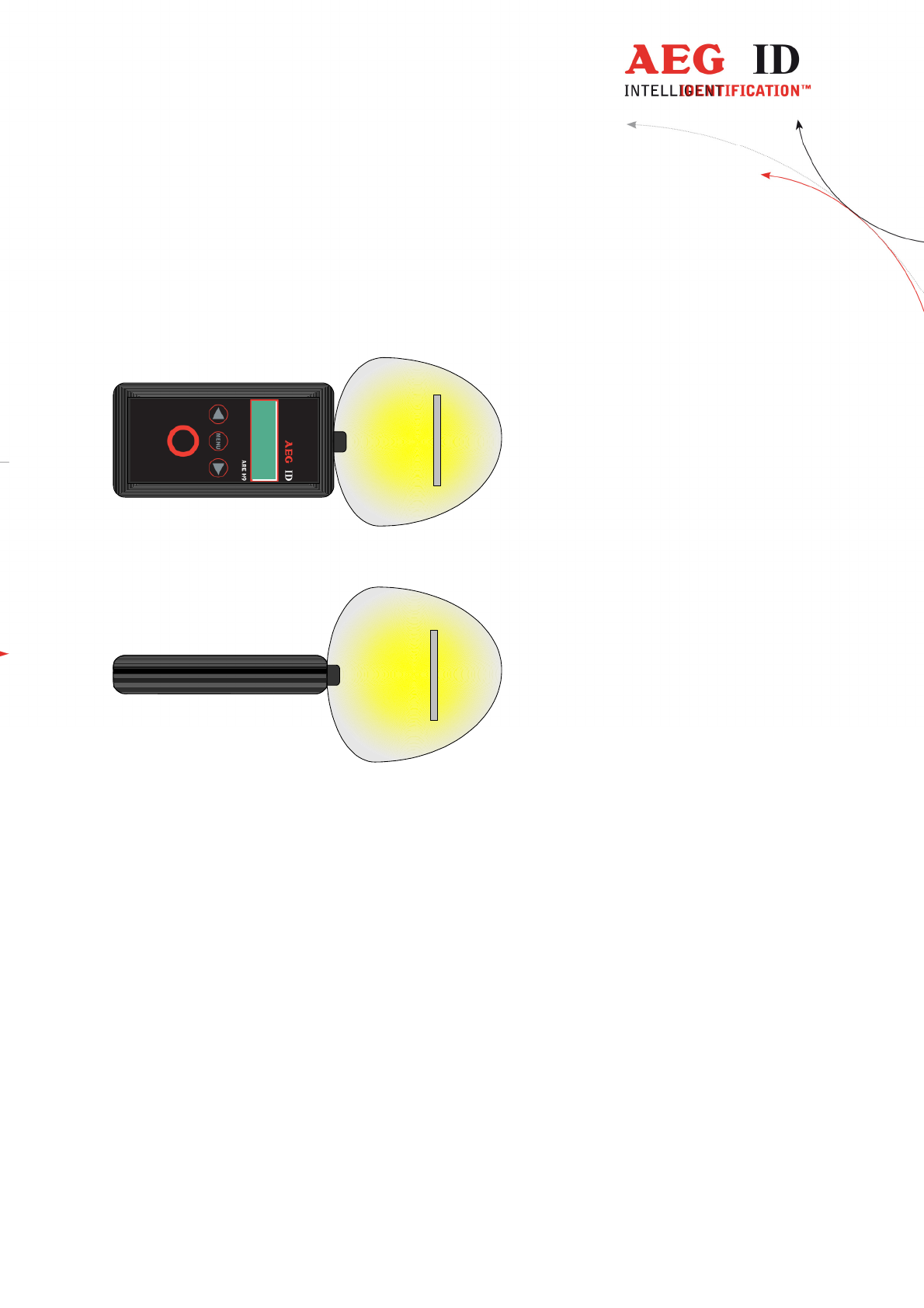
4.2 Orientation with ferrite antenna
The following diagram shows the typical area where a card transponder should
be read:
5 Database
When a reading had been accomplished successfully, in the standard operating
mode, the ARE H9 HF internal database will be checked whether this transponder
code is already stored.
If the new code, in combination with the attribute, is not found in the database, it
will be stored as a new record. This record is composed of the ID-code, the
transponder type and the selected attribute. With the optional real time clock
module date and time of reading will be also stored.
If the new code is already stored in the database, it will be not stored again. In this
case the reader emits 2 successive beeps.
The database is capable to store up to 2016 transponder codes. When the
maximum of the storage is reached no further new code is stored. To store new
codes in this case the database has to be erased.
On Power Loss the ARE H9 HF will keep its database data.
The database of the ARE H9 HF with all its actual records could be transmitted
to a PC. This is done in the Database/USB mode.
---------------------------------------------------------------11/51---------------------------------------
6 Menu functions
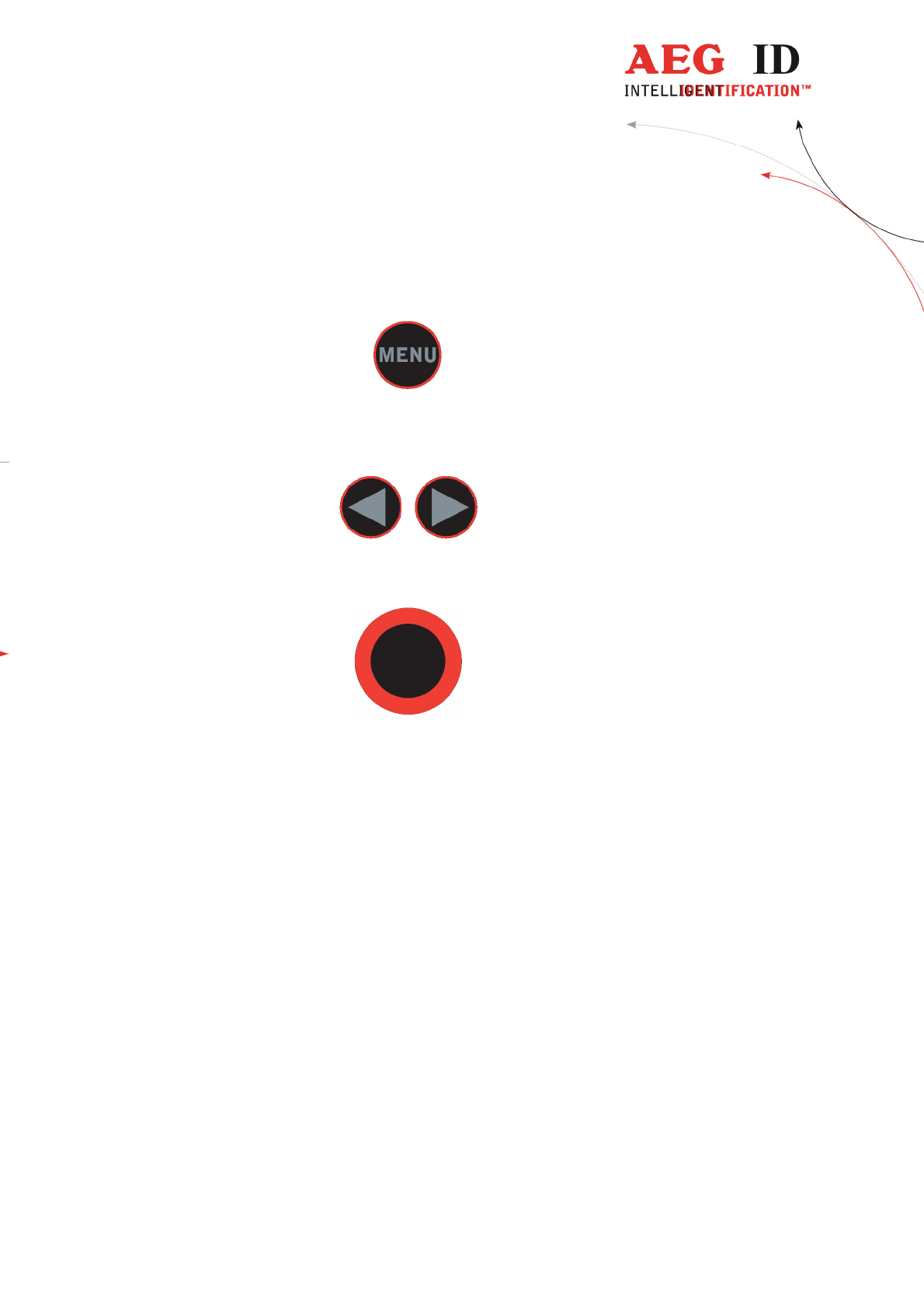
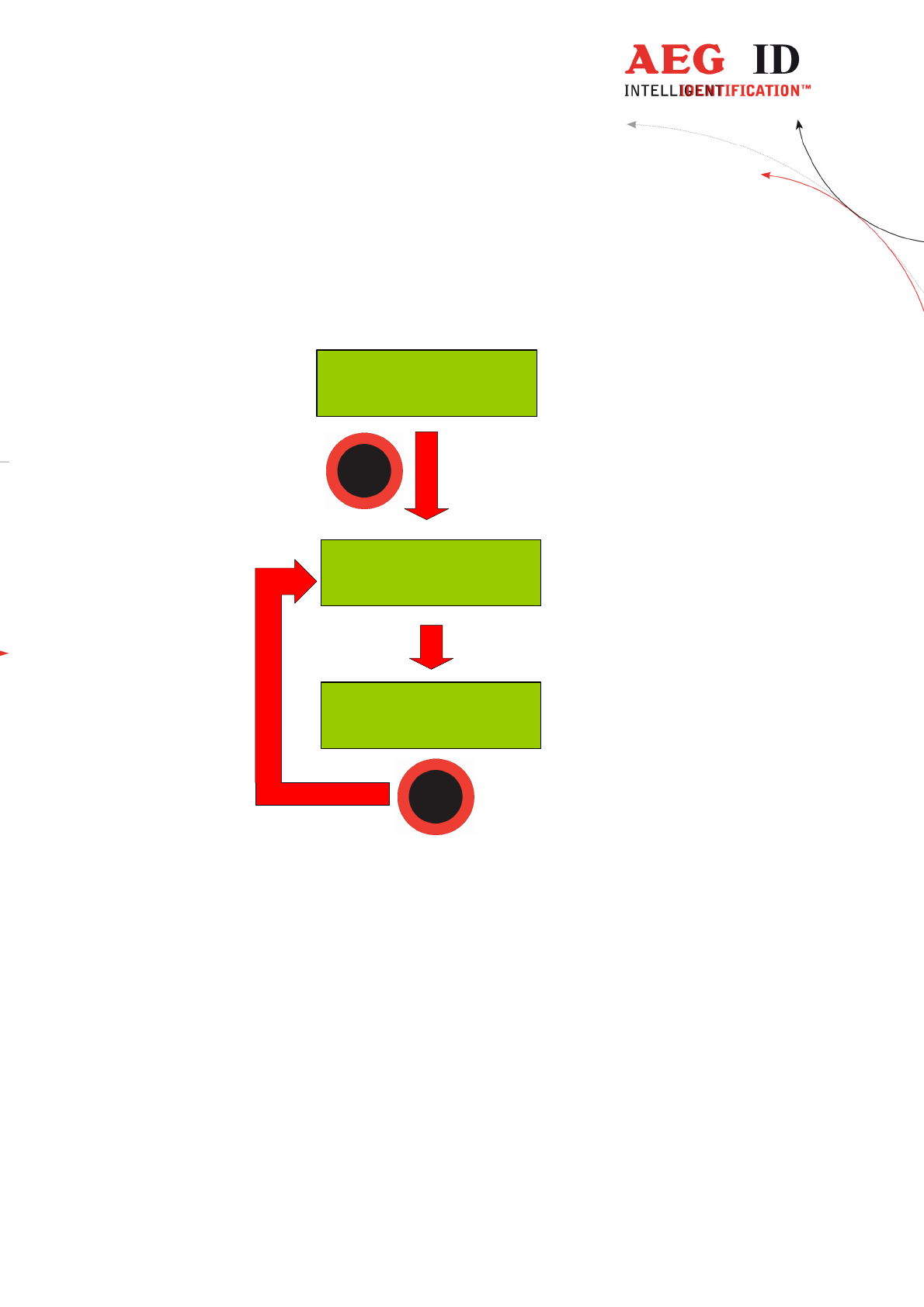
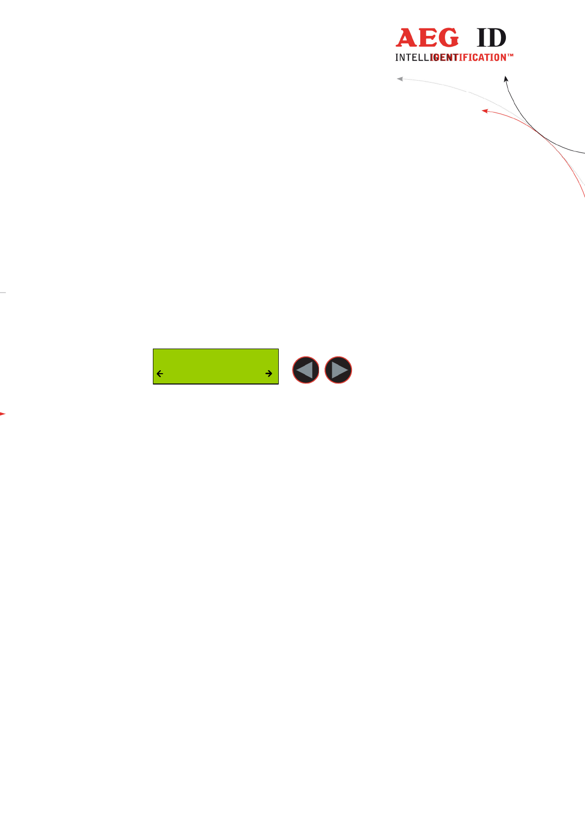
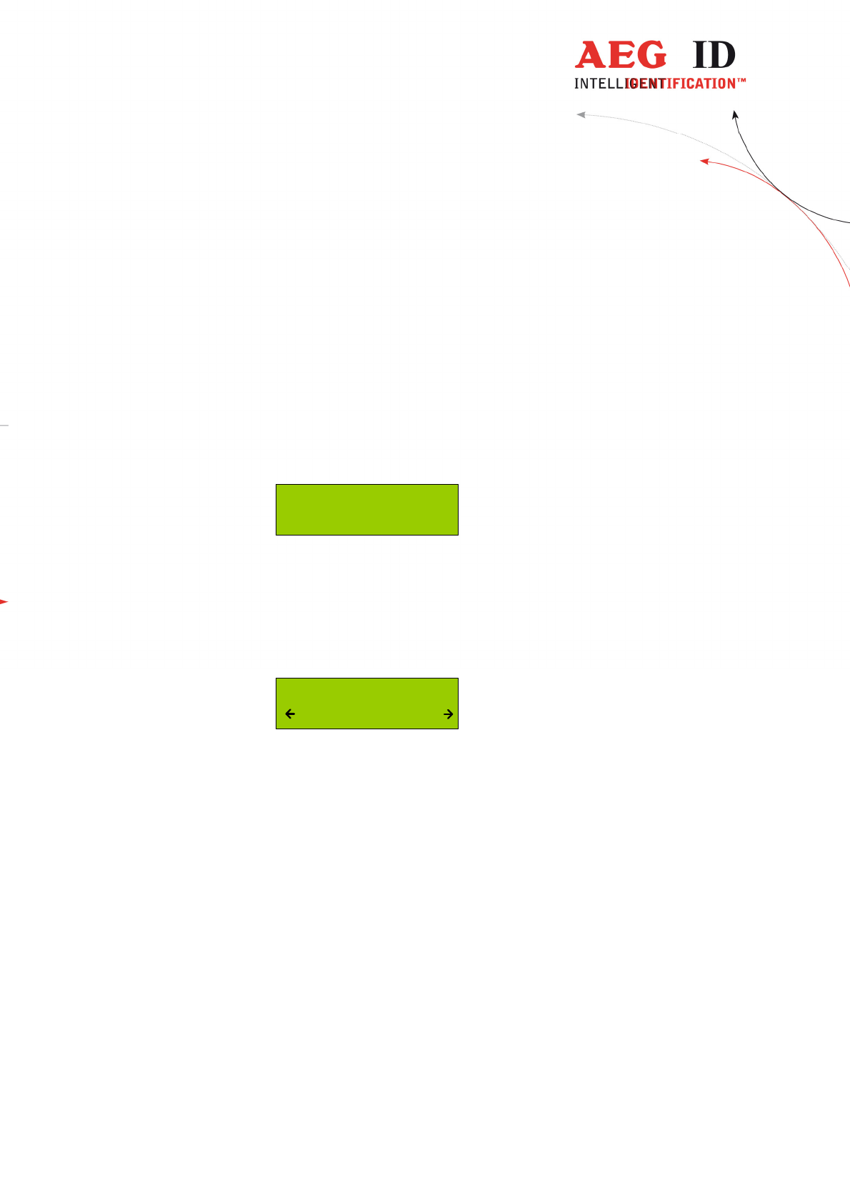
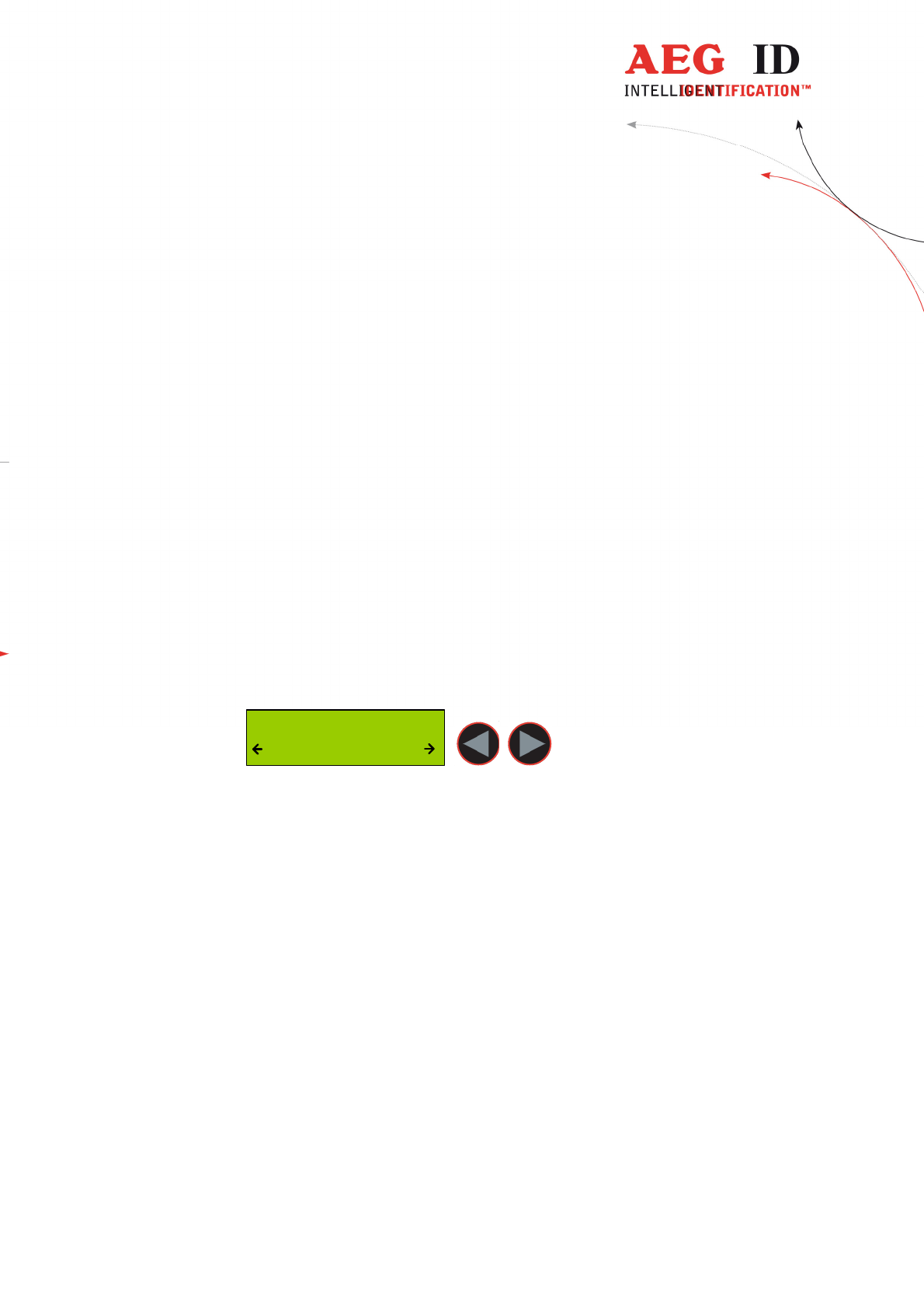
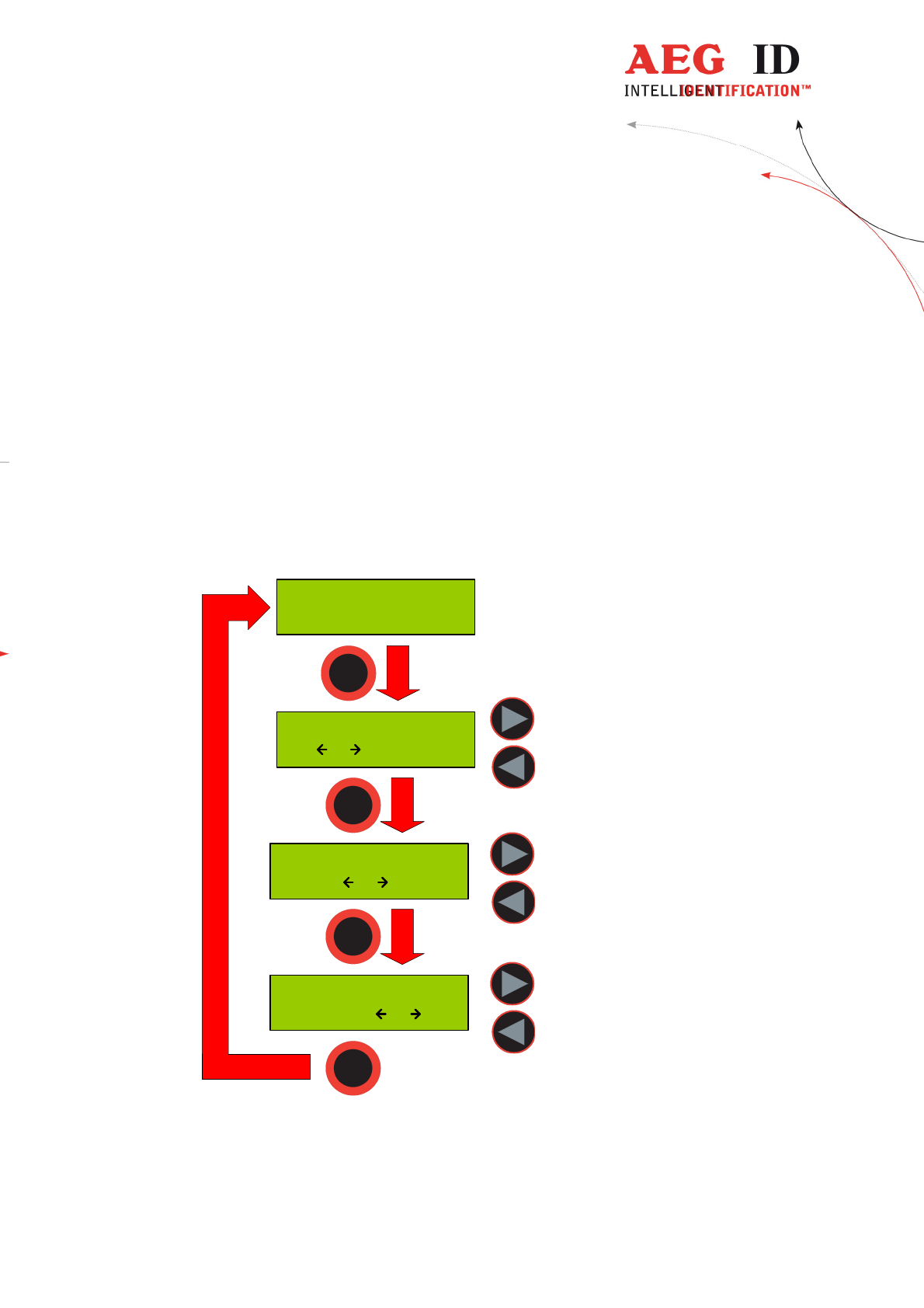
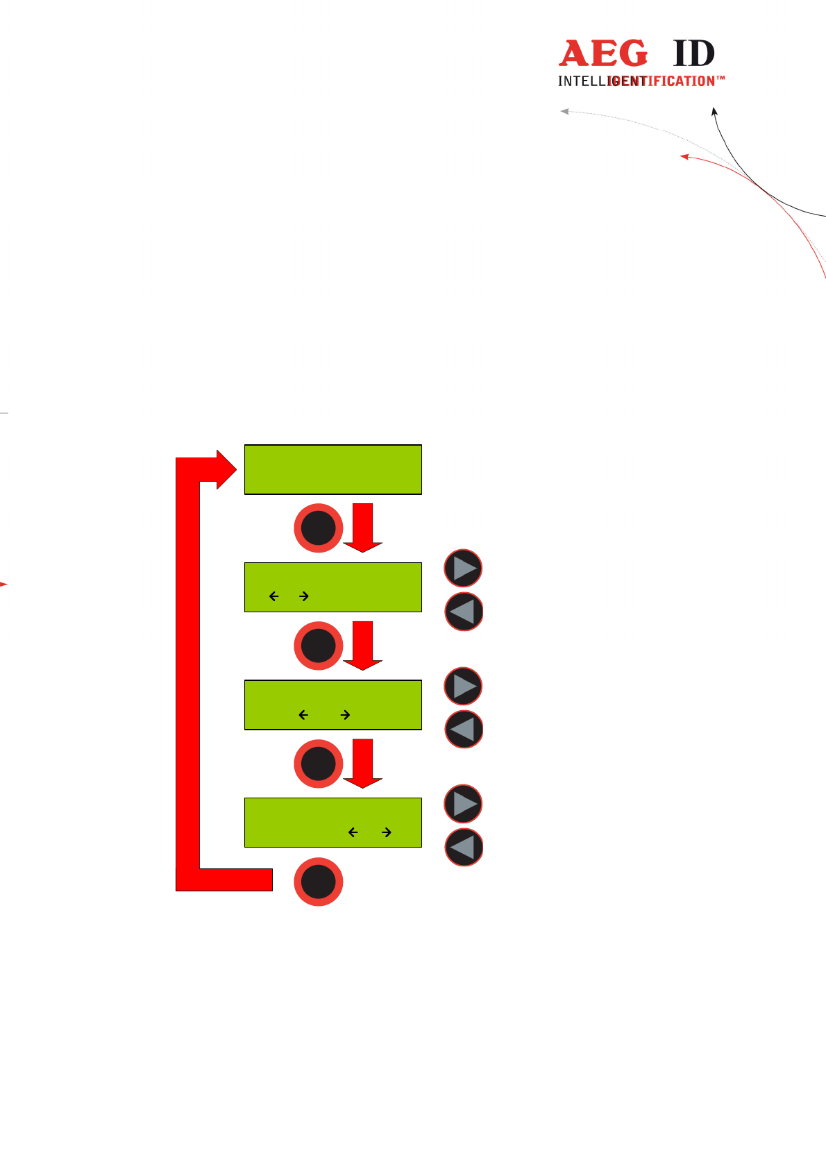
6.1 Navigating trought the menu function
By pressing the menu button it can be chosen between the different menu functions.
If the menu button is pressed again the ARE H9 HF cyclic changes to the next
menu function.
Inside a menu function the setting for the function could be changed with the arrow
buttons.
With the main button the actual menu function setting is selected and the ARE H9
HF changes back to the transponder reading mode.
---------------------------------------------------------------12/51---------------------------------------
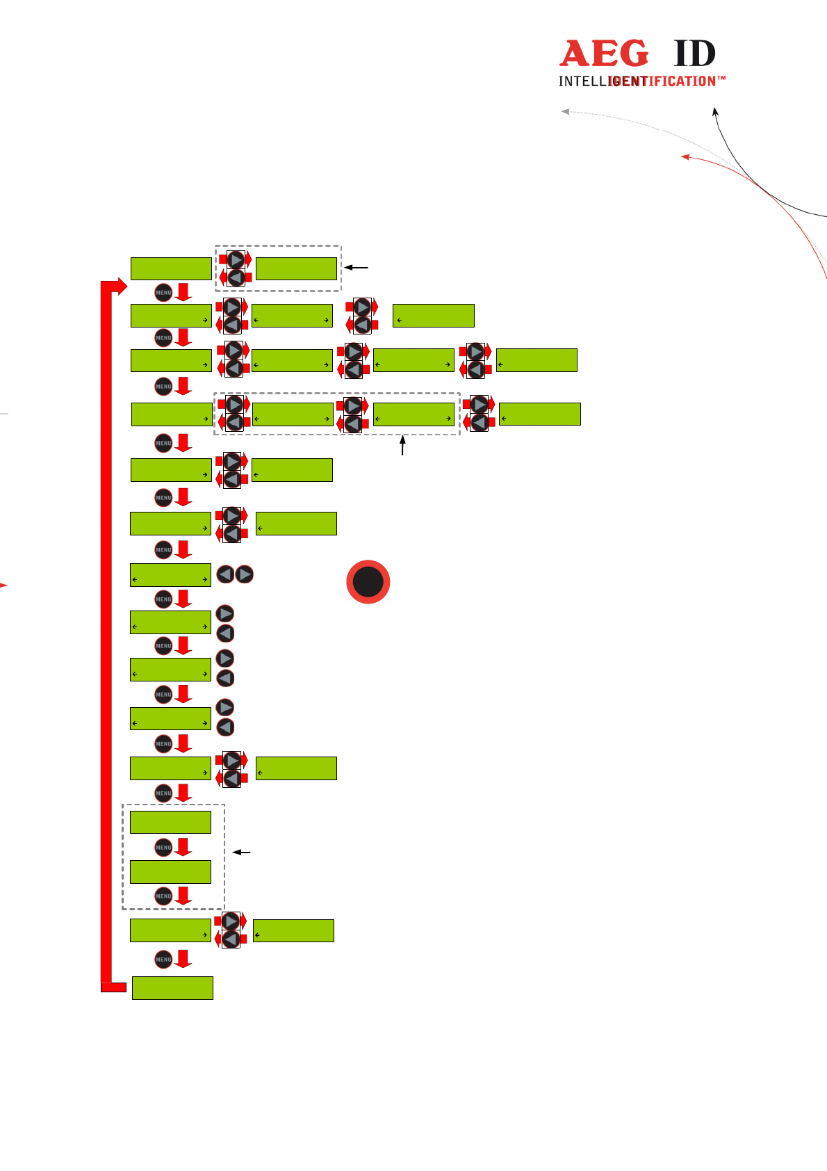
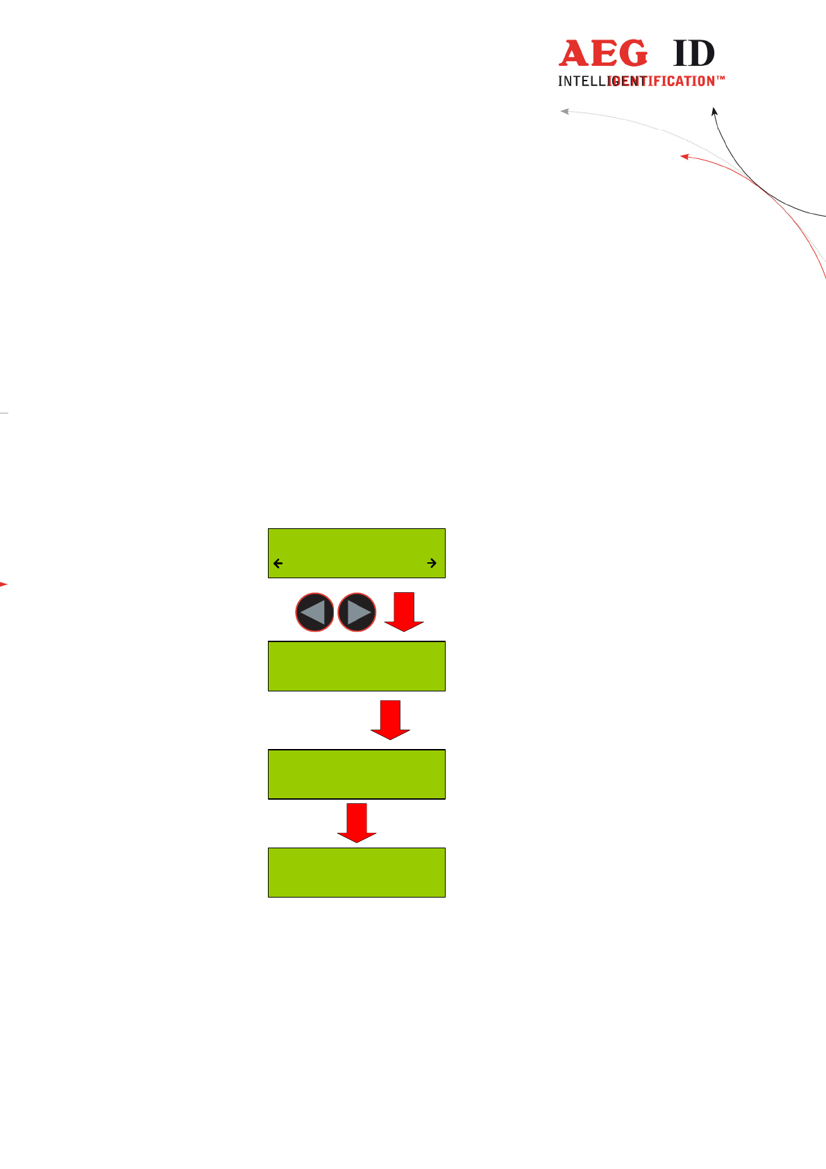
6.2 Overview of the menu functions
Press both arrow
buttons to erase
database memory
+ 0.5 s
- 0.5 s
+ 5 s
- 5 s
+ 0.5 s
- 0.5 s
Press the main
button to select
actual menu option
... ...
Lock Up Reader
Lock
Lock Up Reader
Unlocked
Operating Mode
Standard
Operating Mode
Online/USB
Operating Mode
Datenbank/USB
Set Attribute
#
Set Attribute
A
Set Attribute
Z
--- No Tag ---
Erase DB-Memory
Confirm ?
Reading Time
2.0 s
Turn-Off Time
20 s
Turn-On Delay
0.5 s
Keyboard Sound
Off
Keyboard Sound
On
Set Time
12:00:00
Set Date
01 Jan '10
01 Jan '10
12:00:00
available only with
Real-Time-Clock
module
available only with Real-
Time-Clock module
AEG ID-ARE H9 HF
V1.20015 B
Language/Sprache
Deutsch
Language/Sprache
English
available only with
optional Bluetooth
module
Operating Mode
Online/USB H
Set Interface
USB
Set Interface
Bluet. Slave
Set Interface
Bluet. Master
Set Interface
HID Keyboard
Mirror Code
On
Mirror Code
Off
---------------------------------------------------------------13/51---------------------------------------
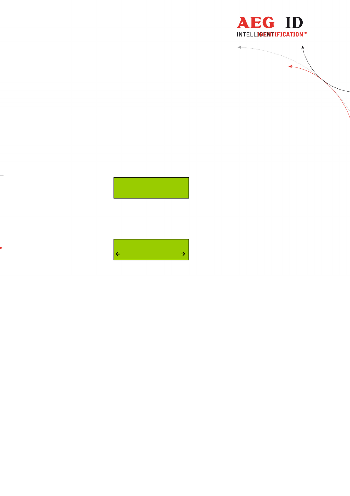
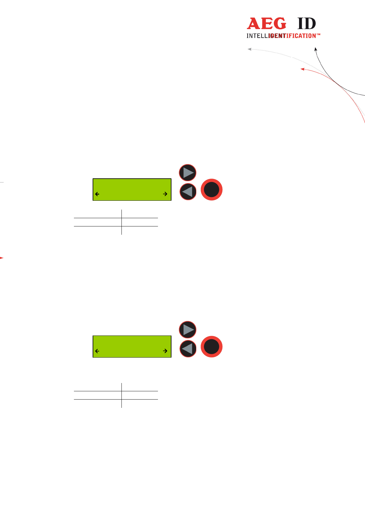
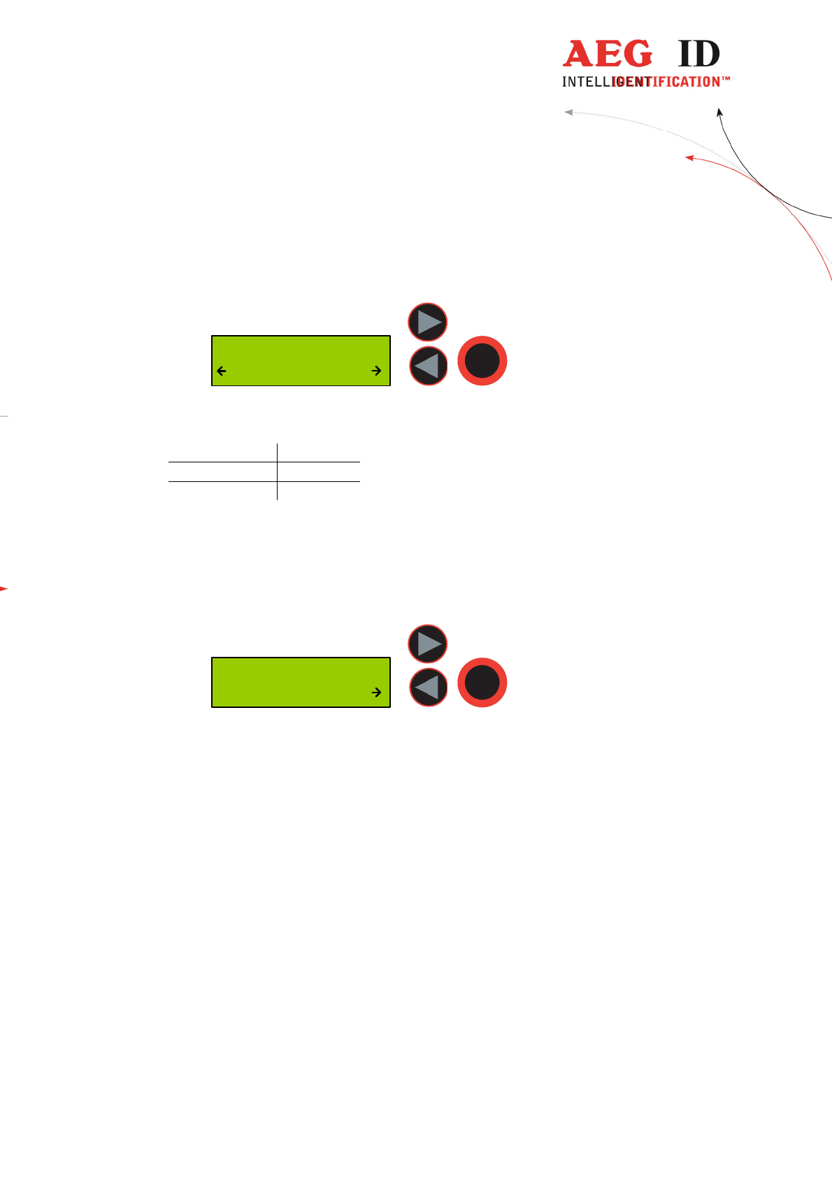
6.3 Set Attribute
With “Set Attribute” one of 27 attributes could be selected for the next read
transponder.
The selection is done by the left/right arrow buttons and confirmed by pressing
the main button.
Set Attribute
#
In standard read mode this selected attribute will be stored together with the
transponder ID-code of the next read transponder in the internal database of the
ARE H9 HF.
Example of Transponder-ID with no attribute:
4C8C8415
ISO-14443A #
ID
type of transponder
attribute
In the initial configuration all the 27 attributes available have a standard text
assignment.
#, A, B, C,D,E,F,G,H,I,J,K,L,M,N,O,P,Q,R,S,T,U,V,W,X,Y,Z
With a PC-software and using the Database/PC mode of the ARE H9 HF it is possible
to assign each attribute a custom text with up to 14 ASCII characters.
Example:
A becomes "stable",
B becomes "pasture"
C becomes "vaccination"
Under “Set Attribute” at the ARE H9 HF it is now possible to select the attribute by
this custom text.
---------------------------------------------------------------14/51---------------------------------------
When a transponder has been read with an attribute set up with a custom text, the text
assigned to the attribute will now be shown on the lower line of the display, right
justified, instead of the attribute.
Example of Transponder-ID with attribute and assigned text “Stall”:
4C8C8415
ISO-14443A Stall
ID
type of transponder
attribute
6.4 Operating Mode
The menu “Operating Mode” switches between the following modes:
Standard, Online/USB, Online/USB H und Datenbank/USB Mode
Operating Mode
Standard
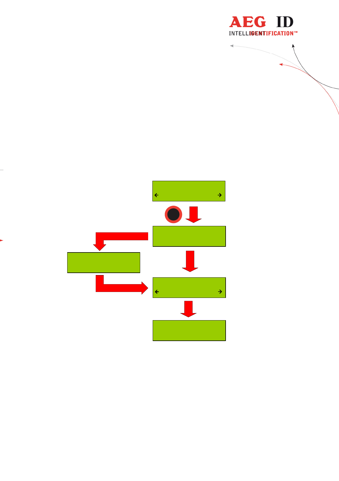
6.4.1 Standard mode
In the “Standard” mode will the read transponder codes stored into the internal
database of the ARE H9 HF.

---------------------------------------------------------------15/51---------------------------------------
6.4.2 Online/USB, Online/BT*) or Online/Ser. mode
In the online mode the transponder codes will not be stored into the internal
database of the ARE H9 HF. The transponder codes are immediately transmitted
via the USB interface to an attached PC, PDA, etc.
It is important that there is a USB **) or Bluetooth*) connection established to a
host-device ready to receive the data; otherwise the read transponder codes are
lost because they are not stored in this mode.
The reading process is the same as in standard mode; the second display-line
shows the information of the selected “online/USB” **) or “online/BT” mode in
between the reading processes.
*)only with optional Bluetooth module
**) online/ser. for Rs232 version
---------------------------------------------------------------16/51---------------------------------------
Once the online mode is active, the ARE H9 HF will be automatically in the
online mode when it switched on again after switched off.
--- No Tag ---
- Online/USB -
4C8C1C84
- Online/USB -
Scanning ...
- Online/USB -
To leave the mode “Online/USB” under “Operating Mode” another mode has to
be selected.

---------------------------------------------------------------17/51---------------------------------------
6.4.3 Online/USB H, Online/BT H*) or Online/Ser. H mode –
handshake mode
The “online/USB H” or “online/BT H” mode has a similar to the “online/USB”
with the difference that a read transponder code will not be sent immediately to
the host (PC, PDA, etc.).
First the reader checks if a connection to the host is established before it sends
the transponder code.
*)only with optional Bluetooth module
**) online/ser. for Rs232 version
---------------------------------------------------------------18/51---------------------------------------
For this transmission the following protocol is used:
ARE H9 HF Host (PC, PDA, etc.)
<STX> <ETX> ->
<- <STX> <ACK> <ETX>
<STX> < transponder data > <ETX> ->
<- <STX> <ACK> <ETX>
If the transponder ID was read the following is displayed:
4C8C1C84
transmitting...
Does the host not answer to the <STX> <ETX> protocol of the ARE H9 HF,
then the ARE H9 HF will cyclic transmit the <STX> <ETX> protocol until an
answer of the host is received. During this the following display appears:
Await Connection
Abort ?
The user can cancel this waiting for a response of the host by pressing both
arrow buttons, but in this case the transponder ID will not be transmitted.
---------------------------------------------------------------19/51---------------------------------------
6.4.4 Database/USB or Database/BT*) mode
In the database mode it is not able to read a transponder. It is intended to
transmit and receive record sets of the ARE H9 HF internal database to a host
device as a PC, PDA, etc.
To exchange data in the database mode you find a software called reader-
terminal on the CD.
The usage of this software is explained in an extra document included with the
software.
You can find the description of the communication protocol in chapter 7.
The database mode can be terminated by pressing both arrow buttons
simultaneously, or by initiating it by the PC communication.
Communic. Active
Abort ?
During the Database/PC mode the ARE H9 HF will not switch off automatically.
*)only with optional Bluetooth module
6.5 Set interface
With this menu option you can choose the interface of the ARE H9 HF. If there
is the optional Bluetooth module available, you also can choose the Bluetooth
interface:
- USB **)
- (Bluetooth Slave)
- (Bluetooth Master)
- HID Keyboard
The ARE H9 HF supports only Bluetooth connection with the serial Port profile.
6.5.1 Interface USB **)
USB is the default configuration of the ARE H9 HF. With this option enabled
the complete communication to and from the ARE H9 HF is done by the USB
cable connection.
Choosing USB as interface automatically disables any active Bluetooth
connection.

---------------------------------------------------------------20/51---------------------------------------
The USB connection to the ARE H9 HF is established as an additional com port
via a USB bridge driver on the host PC. The protocol uses the RS232
specification with the settings:
19200 Baud, 8 Data bits, no party bit, one stop bit, no hardware handshake.
**) serial for Rs232 version
---------------------------------------------------------------21/51---------------------------------------
6.5.2 Set interface to Bluetooth slave
This menu option configures the ARE H9 HF as Bluetooth slave. With the ARE
H9 HF as Bluetooth slave the Bluetooth-connection is established up by the
Bluetooth-partner which is configured as master.
The ARE H9 HF checks after the selection of this option if there is an active
Bluetooth connection, in this case this connection will be closed.
Then the ARE H9 HF is waiting until a Bluetooth connection is established or
the user cancels the operation by pressing both arrow buttons. During this
operation the ARE H9 HF will not switch off automatically.
Verify Blutooth
Connection
Await Connection
Abort ?
Closing active
Connection
Connected as
BT Slave
Set Interface
Bluet. Slave
---------------------------------------------------------------22/51---------------------------------------
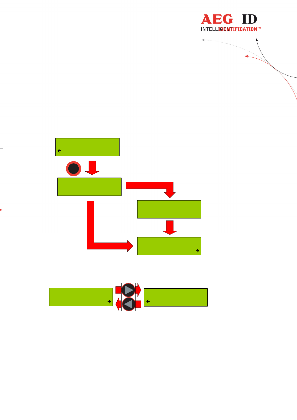
6.5.3 Set interface to Bluetooth master
This menu option configures the ARE H9 HF as Bluetooth master. In this
configuration a Bluetooth connection with an partner is established by the ARE
H9 HF.
In case there is still an active Bluetooth connection, this connection will be
closed before a new one is established.
BluetoothPartner
PC_007
Verify Bluetooth
Connection
Closing active
Connection
Set Interface
Bluet. Master
Was there a Bluetooth partner for the master connection configured before, this
partner will be displayed as default option in the following dialog.
BluetoothPartner
new search
BluetoothPartner
PC_007
By pressing the arrow keys it is possible to switch the selection between the
default partner and a new partner search.
By choosing the default partner, the ARE H9 HF will try to establish a
connection.
During this process the message “Await Connection” could appear when the
partner is not ready or at the partner side additional activities are necessary.
---------------------------------------------------------------23/51---------------------------------------
BT Connecting to
PC_007
Connected with
PC_007
Await Connection
Abort ?
BluetoothPartner
PC_007
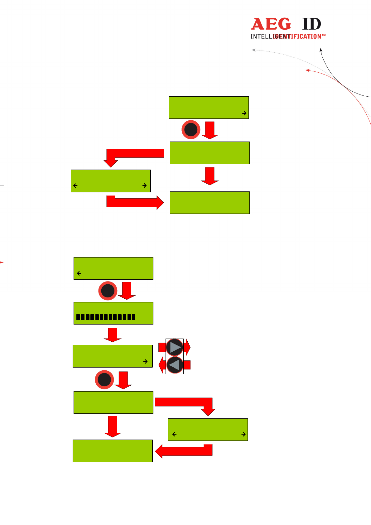
“new search” starts a search process for Bluetooth devices in range of the ARE
H9 HF.
The Bluetooth device search could last some seconds.
Bluetooth Search
2
New BT Partner
PC_007
BT connecting to
PC_007
Connected with
PC_007
Await Connection
Abort ?
BluetoothPartner
new search
---------------------------------------------------------------24/51---------------------------------------
If the search was successful a selection of possible partners will be shown. The
Bluetooth partner search can’t detect if a Bluetooth device supports the serial
port profile, the user has to know this. If the search was not successful the ARE
H9 HF switches back to the “Set Interface” menu.
After choosing a partner from the found devices, the ARE H9 HF will try to
establish a connection.
During this process the message “Await Connection” could appear when the
partner is not ready or at the partner side additional activities are necessary.
(Code 0000)
A successful connection will be shown as follows:
Connected with
PC_007
6.5.4 Bluetooth disconnect
If the connection to the Bluetooth partner is lost during the operating of the
ARE H9 HF, or maximum Bluetooth distance has exceeded, the following
display appears:
Await Connection
Abort ?
In this case will the ARE H9 HF wait as long as the connection is established
again ort he user cancels this screen by pressing both arrow buttons.
While switching off the ARE H9 HF the Bluetooth connection to a partner will
be automatically disconnected.
6.5.5 Set interface to HID Keyboard
If HID keyboard is selected as interface then every read transponder-ID will be
sent as keyboard input to a connected PC.
When HID-keyboard is selected the operating mode of the ARE H9 HF changes
automatically to the “Online/Keyboard” and there is no other “Mode of
Operation” available.
If there is a Bluetooth connection active, the ARE H9 HF closes this connection.
By pressing the left button in the standard display the reader sends “carriage
return” (13/0x0D).
---------------------------------------------------------------25/51---------------------------------------
6.5.6 Interface RS232 **)
If the ARE H9 HF Rs232 is used on a PC a RS232-crossover (lines Rxd, Txd
are crossed) is necessary.
In operation mode “Database/Ser.” and “online” are the following
communication settings in use:
9600 baud, 8 data bits, no party bit, one stop bit, no hardware handshake
**) only in Rs232 version
6.6 Lock up reader
When lock up reader is activated the ARE H9 HF switches of immediately. After
switching on the pocked reader again it shows that it is locked.
During the ARE H9 HF is locked neither a reading process could started nor the
menu could be accessed.
While it is not unlocked, it will switch off again after 5 (default) seconds no
button is pressed.
To leave this mode press both arrow buttons simultaneously.
Unlock Reader !
Press Both
---------------------------------------------------------------26/51---------------------------------------
6.7 Mirror Code
This function allows to mirror the transpondercode byte by byte. It is done in the
reading routine. That means that the code is stored in the database in the same
format as it is shown on the display or is sent via the interface. One transponder
with “Mirror Code” on/off is treated like two different transpondercodes.
Example: -“Mirror Code” off: 12345678
-“Mirror Code” on: 78563412
6.8 Erase memory
This function allows deleting all records in the internal database of the ARE H9
HF. For safety reasons this function is activated only when both arrow buttons
are pressed simultaneously.
Erase DB-Memory
DB erased !
Erase DB-Memory
erasing...
Erase DB-Memory
Confirm ?
--- No Tag ---
~15
seconds
The erasing of the database memory can take several seconds.
! Do not disconnect the ARE H9 HF from the power supply during this
erase operation; this could lead to damaging the database function of the
reader.
---------------------------------------------------------------27/51---------------------------------------
After the erase operation has finished the device will return to the standard
operating mode.
6.9 Reading time
This sets the time frame for one reading attempt. The time could be changed
with the arrow buttons in 0,5s steps. A new time is set by pressing the main
button.
Reading Time
2.0 s
Default value 4 s
min. value 0,5 s
max. value 12,5 s
This setting is stored in the device and is still valid after power off/on operation.
For optimal reading performance this setting is recommended to be between 2-4
seconds.
6.10 Turn-off time
Sets the time until the ARE H9 HF will automatically shut off while no button is
pressed or activity lasts. It could be change with the arrow buttons in 5s steps.
Turn-Off Time
20 s
A new time is set by pressing the main button.
Default value 20 s
min. value 10 s
max. value 300 s
This setting is stored in the device and is still valid after power off/on operation.
---------------------------------------------------------------28/51---------------------------------------
6.11 Turn-on delay
Sets the time the main button is to be pressed to switch on the ARE H9 HF.
The time could be changed with the arrow keys in 0,5s steps.
Turn-On Delay
0.5 s
A new time is set by pressing the main button.
Default value 0,5 s
min. value 0 s
max. value 5 s
This setting is stored in the device and is still valid after power off/on operation.
6.12 Keyboard sound
Here the beep sound of the keyboard could turn on or off.
Keyboard Sound
On
This setting is stored in the device and is still valid after power off/on operation.
---------------------------------------------------------------29/51---------------------------------------
6.13 Set time (available only with Real-Time-Clock module expansion)
This menu option sets the time of the optional Real-Time-Clock module
expansion. With this expansion module it is possibly to add the time and date
code of reading to the transponder ID in the database. The Real-Time Clock
module is equipped with a own backup-battery to hold the time and date even if
the ARE H9 HF is switched off or the main battery of the ARE H9 HF has to be
changed.
To set the time press select this option with the main button, now is it possible to
change the hours with the left/right arrow button. The hour setting is accepted by
pressing the main button; then the minutes and seconds can be changed. The
minute and second setting is working in the same way as the hour setting. After
setting the second the Real-Time-Clock will be synchronized with this new time.
To abort the processes during Set Time press the menu button.
Set Time
12:00:00
Set Hour
12 00:00
Set Minute
12 00 00
Set Second
12:00 00
+ 1 h
- 1 h
+ 1 m
- 1 m
+ 1 s
- 1 s
---------------------------------------------------------------30/51---------------------------------------
6.14 Set date (available only with Real-Time-Clock module expansion)
This menu option sets the date of the optional Real-Time-Clock module
expansion.
To set the date select this option with the main button, now is it possible to
change the day of month with the left/right arrow button. The day setting is
accepted by pressing the main button; then the months and years can be changed.
The month and year setting is working in the same way as the day setting. After
setting the second the Real-Time-Clock will be synchronized with this new date.
To abort the processes during Set Date press the menu button.
Set Date
01 Jan '10
Set Day
01 Jan '10
Set Month
01 Jan '10
Set Year
01 Jan 10
+ 1 y
- 1 y
+ 1 m
- 1 m
+ 1 d
- 1 d
---------------------------------------------------------------31/51---------------------------------------
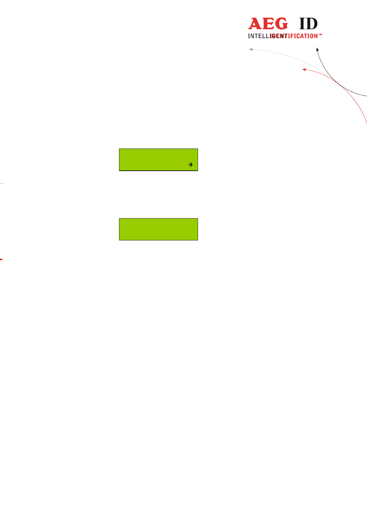
6.15 Language/Sprache – select display language
With this menu option is it possible to change the language of the ARE H9 HF
menu-display.
Language/Sprache
English
6.16 Reader version
This menu option shows the Firmware Revision of the ARE H9 HF.
AEG ID - ARE H9
V3.00136
7 Data exchange protocol
7.1 Set of commands
It includes the following commands:
ET: check, whether Flash memory is empty
EC: clear Flash memory
RP: set Pointer on the first Record of stored data in the memory
RN: read the stored Record and increase the Pointer
RL: repeat the previous reading (RN) of stored Record without changing the
Pointer
WP: set Pointer on the next free position in the memory
W: write a Record into Flash memory and increase Pointer
SV: read Software Version
XT: stop communication, abandon operating mode database/USB and go change
to the standard read mode.
R: Set date and time
T: attach Text (with up to 14 characters) with attributes 'A' to 'Z' (e.g.
'Gate' instead of 'A')
---------------------------------------------------------------32/51---------------------------------------
7.2 Protocol structure
All the commands have the following structure:
STX, command in ASCII, CRC in ASCII, ETX
The following answers are possible:
A Record with the structure given above,
ACK
BEL
NAK
Except STX and ETX, the total content of the commands are composed in
ASCII characters.
This procedure has been chosen explicitly, as a large number of host Operating
Systems react with their own functions, when they see characters outside of 0x20
to 0x7F.
The CRC is applied only on the characters of the „command“, STX and ETX are
not included.
The 4 nibbles of the CRC are transmitted in form of 4 ASCII characters. By
doing so, the CRC is in conformance with the ASCII standard as well.
Control
Control Control
Control
characters
characterscharacters
characters
Hex
Hex Hex
Hex
code
codecode
code
Designation
DesignationDesignation
Designation
Function
FunctionFunction
Function
STX 0x02 Start Of Text Begin of a Records
ETX 0x03 End Of Text End of a Records
BEL 0x07 buzzer (bell) Signaling a specific condition, e.g..
if the interrogated memory site is
not occupied.
CR 0x0D Carriage Return End of string
ACK 0x06 Acknowledge The command has been executed
successfully
NAK 0x15 Negative Acknowledge The command was not recognized
and consequently has not been
executed (syntax error)
---------------------------------------------------------------33/51---------------------------------------
7.3 Checksum CRC
The check sum (CRC=cyclic redundancy check) is generated using the
standardized
ISO-Polynomial (or CRC-CCITT) 0x1021; P(X) = X16 + X12 + X5 + 1 .
CRC-CCIT Polynom 0x1021
CRC order 16 Bit
Initial CRC-value 0x0000
data stream reverse each data byte (process from LSB to MSB)
CRC reverse CRC result before final XOR

---------------------------------------------------------------34/51---------------------------------------
Example in ANSI C:
The CRC checksum in this software example is implemented as a reverse CRC-
CCITT:
The check sum is always composed out of 4 hex characters (values from 0x0000
to 0x FFFF). These 4 hex characters are transmitted in ASCII code from '0' ..
'9' and 'A' to 'F' .
Example: The check sum 0E2A is transmitted as CHR(0x30), CHR(0x45),
CHR(0x32), CHR(0x41).
// *********************************************************************
// Function to calculate the CRC from a protocol buffer with
// the given length
// *********************************************************************
unsigned int build_crc(unsigned char length, unsigned char* protocol)
{
// the initial CRC value
#define CRC_PRESET 0x0000
// the reverse CRC-CCIT pollynomial
#define CRC_POLYNOM 0x8408
unsigned char i,k;
unsigned int crc;
unsigned char crc_in;
crc CRC_PRESET; // initial value
for(i=0;i< length;i++) // loop trough the protocol
{
crc_in = protocol[i]; // get next protocol byte
for (k=0;k<=7;k++) // loop trough one byte LSB to MSB
{
// test each Bit for CRC calculation
if((((crc_in>>k)&0x01)^(crc&0x0001))==1)
{ crc=crc>>1; crc=crc^0x8408; }
else
{ crc=crc>>1;}
}
}
return(crc);
}
---------------------------------------------------------------35/51---------------------------------------
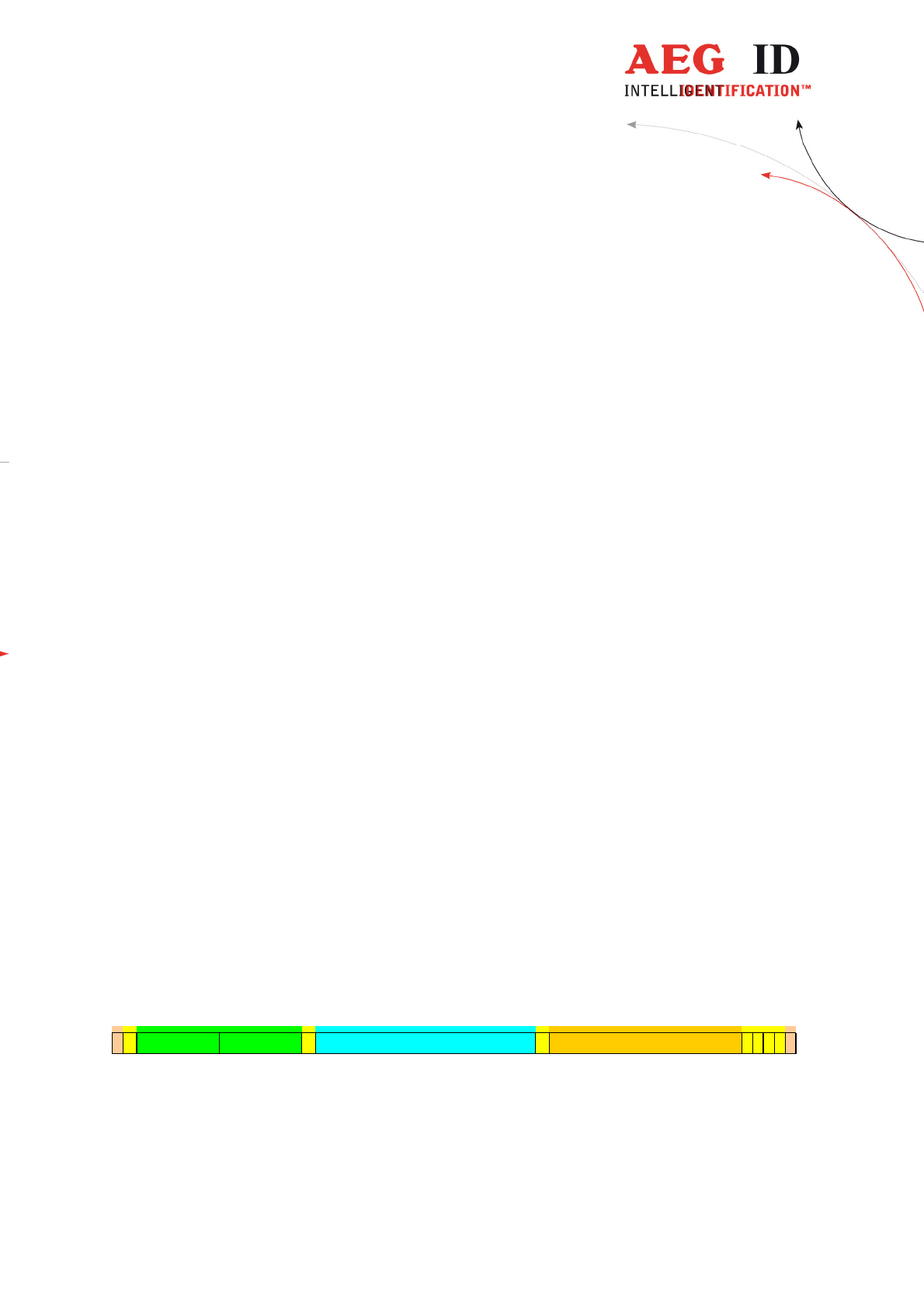
7.4 Structure of the data base
1 Byte for Attribute (# = no attribute, ‘A’ ... ‘Z’) - transmitted as 1 ASCII-
character
6 Byte for Date/clock in BCD-Format - transmitted as 12 ASCII- characters
1 Byte for Code length (1 ... 16) - transmitted as 1 ASCII- character '0' .. '9',
'A' .. 'F'
The code length is encoded as follows: Value of the ASCII-character =
hex character describing (length – 1).
Example: length =16; length - 1 =15; hex character = 0xF; ASCII-
character = 'F' = CHR(0x46).
8 Byte for the Code (up to 16 nibbles, starting left ) - transmitted as 16 ASCII-
characters
1 Byte for Type of transponder - transmitted as 1 ASCII- character
0 = no known transponder
1 = ISO-FDX
2 = ASK 64Bit
3 = Trovan
4 = Datamars
5 = Destron
6 = ISO-Hdx
7 = Hitag 1/S
8 = Hitag 2
9 = Pontech
A = PSK 2
B = PSK 1
C = PSK 2
D = BDE FDX
E = BDE HDX
F = ISO 14443A 4 Byte
G = ISO 14443A 7 Byte
H = ISO 15693
U = EM 4305
14 Byte for Text (up to 14ASCII’s in the range 0x20 ... 0x7F) - transmitted as
14 ASCII- character
K010101000133F2858997D3A4F00001______________45F6
STX
Attribute
Length
Type
CRC
CRC
CRC
CRC
STX
0 1 2 3 4 5 6 7 8 9 10 11 12 13 14 15 16 17 18 19 20 21 22 23 24 25 26 27 28 29 30 31 32 33 34 35 36 37 38 39 40 41 42 43 44 45 46 47 48 49 50
Date Time Code (64Bit) Text
Example: description of a record – (sequence of characters at the interface):
STX 'K010101000133F2858997D3A4F00001______________46F6' ETX
---------------------------------------------------------------36/51---------------------------------------
The meaning is as follows:
K = Attribute 'K'
010101 = 1.1.2001
000133 = 00:01:33 time
F = Code length = 16
2858997D3A4F0000 = Code
1 = Type of transponder: ISO-FDX
______________ = 14 characters for text (not used = '_')
46F6 is the relevant CRC-check sum
7.5 Simplified read out procedure, without
programming the CRC-routine
In order to get a quick output of data from the hand held reader, programming
the CRC may be omitted. In this case the following values have to be used:
Command CRC in Hex
‘ET’ 0x2C7F
‘EC’ 0x 4841
‘RP’ 0x B2C2
‘RN’ 0x4B3D
‘RL’ 0x682F
‘WP’ 0xCC7A
‘SV’ 0xCE2C
‘XT’ 0x0996
Example:
In order to read the software version out of the hand held reader , the following
command has to be sent from the PC to the reader: STX ‘SVCE2C ‘ ETX . In
case of a valid result, the answer is for example STX ‘610CE8E’ ETX, where
‘610’ stands for the Version and ‘CE8E’ for the check sum belonging to it.
The disadvantage of this method is: The command ‘W’ can not be executed
because the check sum is computed out of the entire Record ( including the
command and the code number ). The consequence is, that every command in
conjunction with a code number has is own check sum.

---------------------------------------------------------------37/51---------------------------------------
7.6 The command structure in detail
7.6.1 EEPROM (flash memory) empty test
STX , „ET“ , „CRC“ , ETX
answer: ACK = EEPROM contains data
BEL = EEPROM contains no data
NAK = Error
This command checks if the database is empty.
7.6.2 EEPROM clear
... „EC“ ...
answer: ACK = executed
NAK = Error
7.6.3 Set pointer to first full EEPROM record
... „RP“ ...
answer: ACK = executed
NAK = Error
Note: It is absolutely necessary, that this command is executed , before a
readout or clearing command is given. Otherwise the position of the
pointer is undefined.
7.6.4 Read (new) record
... „RN“ ...
answer: STX, „record in ASCII“ , „CRC in ASCII“ , ETX
NAK = Error
The output of the reader is a record ,but, after completion, the pointer is
incremented as well. Consequently at the next "RN" command the following
record will be transmitted.

---------------------------------------------------------------38/51---------------------------------------
7.6.5 Read last record
... „RL“ ...
answer: STX, „record in ASCII“ , „CRC in ASCII“ , ETX
NAK = Error
The reader repeats the output of the record, that was transmitted with the
previous "RN" command. The position of the pointer remains unchanged ( as set
by the previous "RN" command ). This command is sent by the host only , if the
CRC from the last record gives a wrong result.
7.6.6 Set pointer to first empty EEPROM record
... „WP“ ...
answer: ACK = executed
NAK = Error
Note: It is absolutely necessary, that this command is executed , before a load or
write command is given. Otherwise the position of the pointer is undefined.
Caution: stored records may be overwritten.
7.6.7 Write record
STX, „W“ , „record in ASCII“ , „CRC in ASCII“ , ETX
answer: ACK = executed
NAK = Error
This command writes the record into the EEPROM memory, provided that
length, syntax, and CRC have been identified as true. After completion, the
pointer is incremented as well. Consequently at the next "W" command the new
record will be written into the next position.
7.6.8 Software version
... „SV“ ...
answer: STX, „503“ , „CRC in ASCII“ , ETX
NAK = Error
---------------------------------------------------------------39/51---------------------------------------
7.6.9 Exit communication mode
... „XT“ ...
answer: ACK = executed
NAK = Error
7.7 Parameter changing commands
7.7.1 Change parameters
In the operation mode database/PC of the reader it is also possible to change
some parameter of the reader itself e.g. reading time, switch off time etc.
This is done by the command „s“:
Format:
STX, „s“ , „Address = 3xASCII-chr“, „Value = 2xASCII-chr “ , „crc =
4xASCII-chr“ , ETX.
Address
Name Options/Values Parameter-
Range
Default
Value
0x004 Set code
format
Representation of ISO-Codes:
0x00 : hexadecimal
0x01 ISO animal
0x02 ISO industry
0x00-0x02
(0-2)
0x01
(1)
0x00E Turn-off
time
Time until the device will automatically shut
off.
Set in 5 second steps
(Parameter 0xFF=the device
didn’t switch off)
0x02-0x3C
(2-60)
0xFF (255)
0x04
(4)
0x00F Turn-on
delay
The time the main-button is to be pressed to
switch on the reader.
value*0.5s
0x00-0x0A
(0-10)
0x01
(1)
0x010 Reading
time
Sets the time frame for one reading attempt
Value*500ms
0x01 – 0x19
(1 – 25)
0x04
(4)
0x011
Baudrate 0x01 = 9600 Baud
0x02 = 19200 Baud
0x03 = 38400 Baud
0x01 – 0x03 0x02
(19200)
0x012 Keyboard Activates the Keyboard sounds 0x00, 0x01 0x01
---------------------------------------------------------------40/51---------------------------------------
sound 0x00 = off ; 0x01 = on (0, 1) (1)
0x013 Mirror
Code
Activates the Mirror Code
0x00 = off ; 0x01 = on
0x00, 0x01
(0, 1)
0x00
(0)
0x081
HID-
keyboard
language
The keyboard-layout is changed for different
languages
0x07 german
0x09 english
0x0A spanish
0x0C french
0x10 italian
0x13 dutch
0x16 portuguese
0x4B canadian
0x07 0x09,
0x0A,0x0C,
0x10,0x13,0
x16,0x4B
0x07
(german
)
0x82 Specialver
sion
Activate specialversion 0x00-0xFF 0x00 –
no
0x4D –
F12
Answer from reader:
ACK = command executed
NAK = command or parameter error
Example:
Set Reading Time to 4,5 seconds
9*500 = 4500ms = 4,5s
<STX>s01019C872<ETX>
7.7.2 Read parameters
The parameters stored in the ARE H9 HF could be read with the command „S“.
Format:
STX, „S“, „Address = 3xASCII-chr“,crc = 4xASCII-chr“, ETX.
Answer from reader:
STX, „Value 2xASCII-chr“, „CRC 4xASCII-chr“, ETX

---------------------------------------------------------------41/51---------------------------------------
7.7.3 Set time and date
„r“ is the command to set the time and date with a Real-Time-Clock-module
present in the ARE H9 HF.
Date and time are coded as BCD-values and transmitted in ASCII-characters.
Format:
STX, „r“, „Date and Time in ASCII BCD“, „CRC 4xASCII-chr“, ETX
Answer from reader:
ACK = command executed
NAK = command or parameter error
Example:
Set the clock to 15.11.2002, 10:02:16
<STX>r1511021002162CA5<ETX> with CRC = 2CA5
7.8 Attributes
7.8.1 Assign text to attributes
The database in the ARE H9 HF is capable to assign 27 attributes to
transponder-IDs.
In the initial configuration all the 27 attributes available have a standard text
assignment.
#, A, B, C,D,E,F,G,H,I,J,K,L,M,N,O,P,Q,R,S,T,U,V,W,X,Y,Z
Using the Database/PC mode of the ARE H9 HF it is possible to assign each
attribute a custom text with up to 14 ASCII characters.
Example:
A becomes “stable”,
B becomes “pasture”
C becomes “vaccination”
A new text could be assigned to an attribute with the command „t“.

---------------------------------------------------------------42/51---------------------------------------
Format:
STX, „t“, „Attribute = 1xASCII-chr“,„Text = 14xASCII-chr“,„crc =
4xASCII-chr“, ETX.
Answer from reader:
ACK = command executed
NAK = command or parameter error
The text must be minimum three characters and at least 14 characters long. Only
characters of the ASCII-table are allowed in the text.
Should no text be assigned, or an assigned text should be cleared, three „_“-
characters are sent instead of the text.
Example:
To change the attribute a to the text „Stall“ the following protocol has to be
sent:
<STX>tAStall02C9<ETX>
To clear the text of the attribute „A“ the following protocol has to be sent:
<STX>tA___0186<ETX>
7.8.2 Read attribute text assignments
The text assignments to the attributes at the ARE H9 HF could be read by using the
command „T“
Format:
STX, „T“ , „Attribute = 1xASCII-chr“,„crc = 4xASCII-chr“ , ETX.
Answer from reader:
STX, „Attribute = 1xASCII-chr“,„Text = 14xASCII-chr“,„crc = 4xASCII-chr“ ,
ETX.
NAK = command or parameter error
---------------------------------------------------------------43/51---------------------------------------
Example:
To read the text of the attribute „A” following protocol has to be sent:
<STX>TAE71A<ETX>
Answer:
<STX>A538D<ETX> => no text assigned
or
<STX>Stall7A09<ETX> => assigned text „Stall“
8 Control characters used in the online mode
character
value
hexadecimal
Function
<NL> 0x00 zero character, terminates text element
<STX> 0x02 start of text
<ETX> 0x03 end of text
<ACK> 0x06 acknowledge
<CR> 0x0D carriage return
<LF> 0x0A line feed
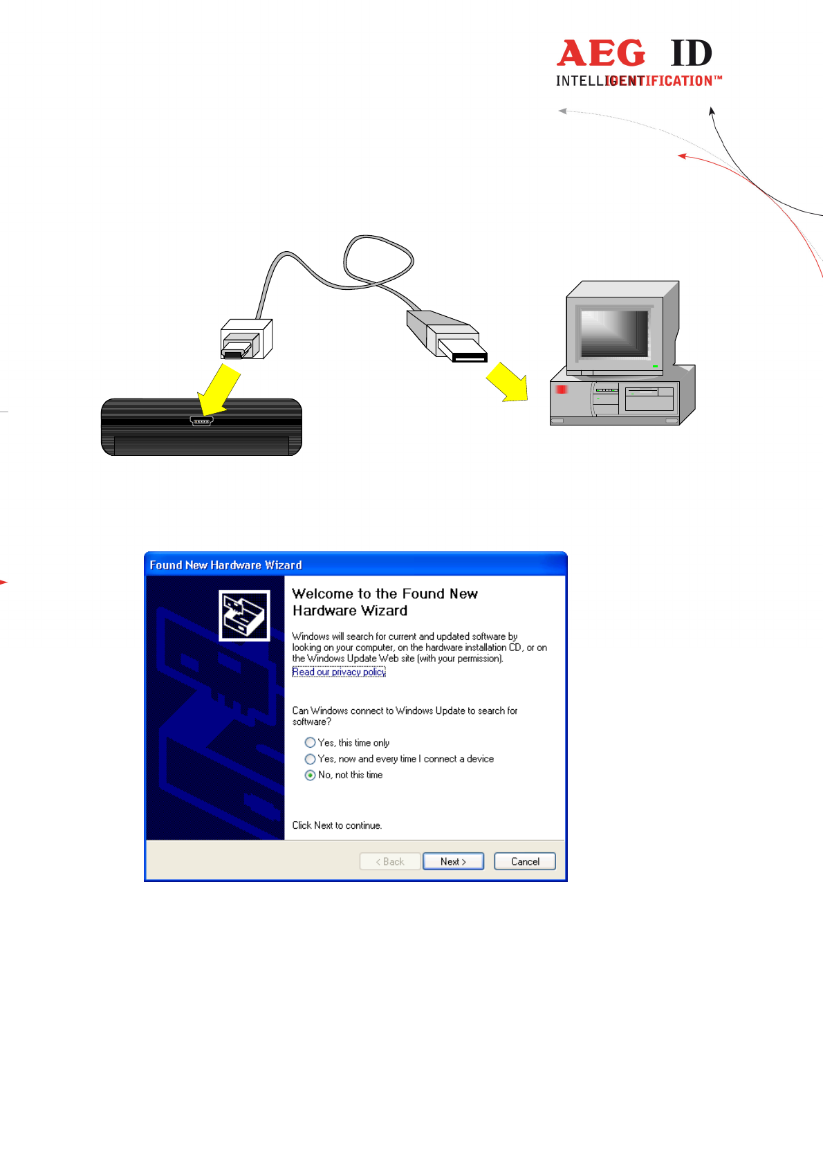
9 USB driver installation
To use the online and the database mode the ARE H9 HF is connected via USB
to a host PC. Before the USB connection could be used a USB to RS232 bridge
drive has to be installed.
If you want to use the USB-HID interface the standard keyboard driver is used.
Insert the driver disc supplied with the ARE H9 HF into your CD-Rom or DVD-
Drive of the host PC you want to use with the pocket reader. Connect the ARE
H9 HF with the supplied USB cable to a free USB port of your PC (USB1.1 and
USB2.0 ports are supported).
---------------------------------------------------------------44/51---------------------------------------
USB connection cable
ARE H9
PC
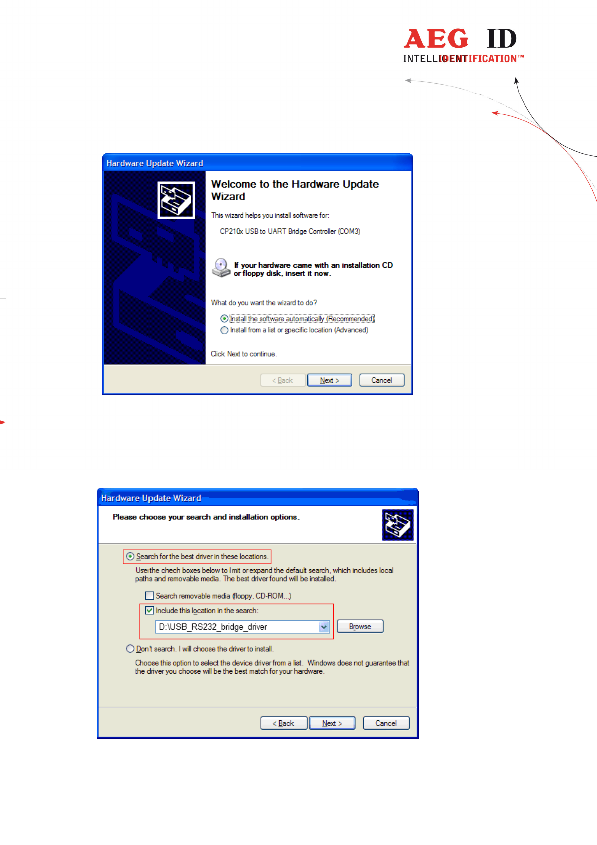
The PC will detect a new hardware; Windows opens the Found New Hardware
Wizard.
If the Found New Hardware Wizard asks to connect to Windows Update, select
„No, not this time“, then click „Next“.
---------------------------------------------------------------45/51---------------------------------------
In the next windows of the Hardware Update Wizard select „
Install from a list or specific
location (Advanced)“.
In the search dialog choose „Search for best driver in these locations“. Specify the CP210x
driver located in the CD folder „..\USB_RS232_bridge_driver“.
---------------------------------------------------------------46/51---------------------------------------
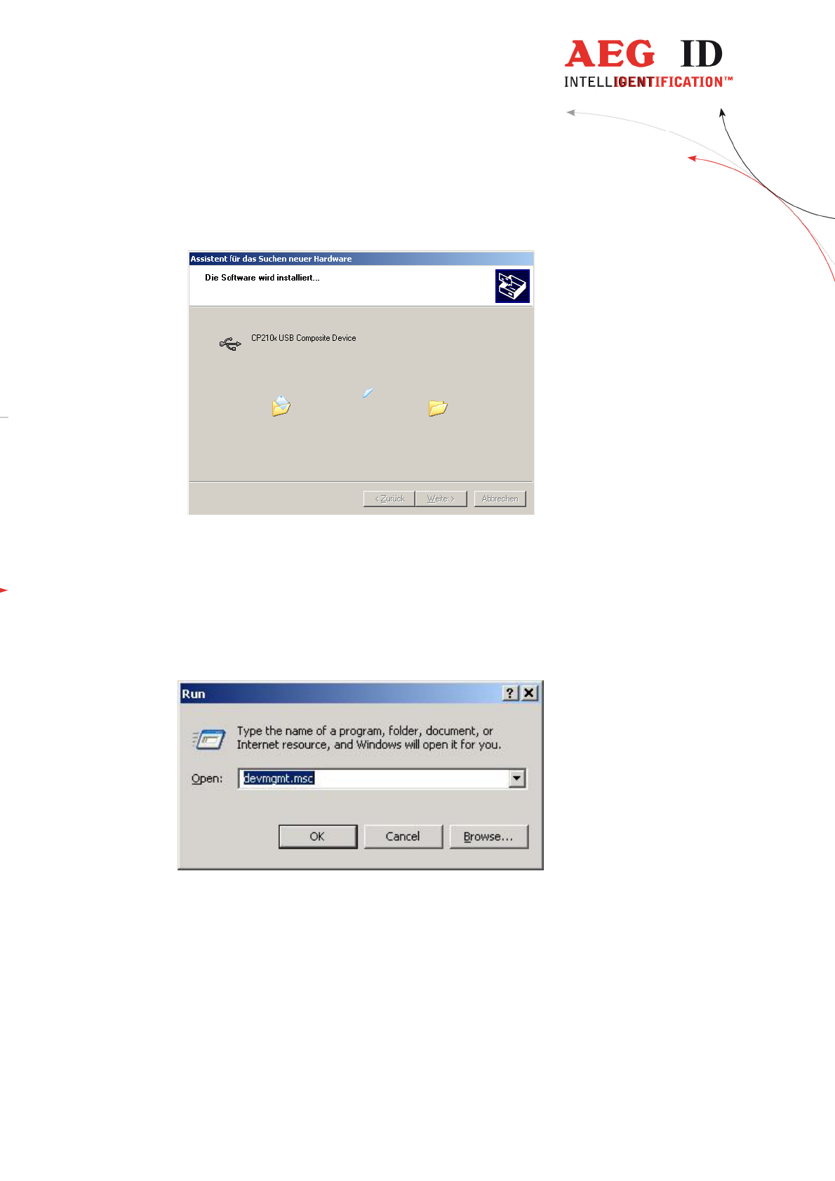
Click „Next“after setting the path to the driver location
This completes the installation of the USB Device Driver.
After the installation of the USB Device Driver the COM port setting could be set
and verified by the Windows Device Manager.
Open the Device Manager using start button -> select Run, type in the text field
„devmgmt.msc“and click „OK“.
Another method is to access the Windows Device Manager is: Start -> Control
Panel -> System -> Hardware -> Device Manager.
---------------------------------------------------------------47/51---------------------------------------
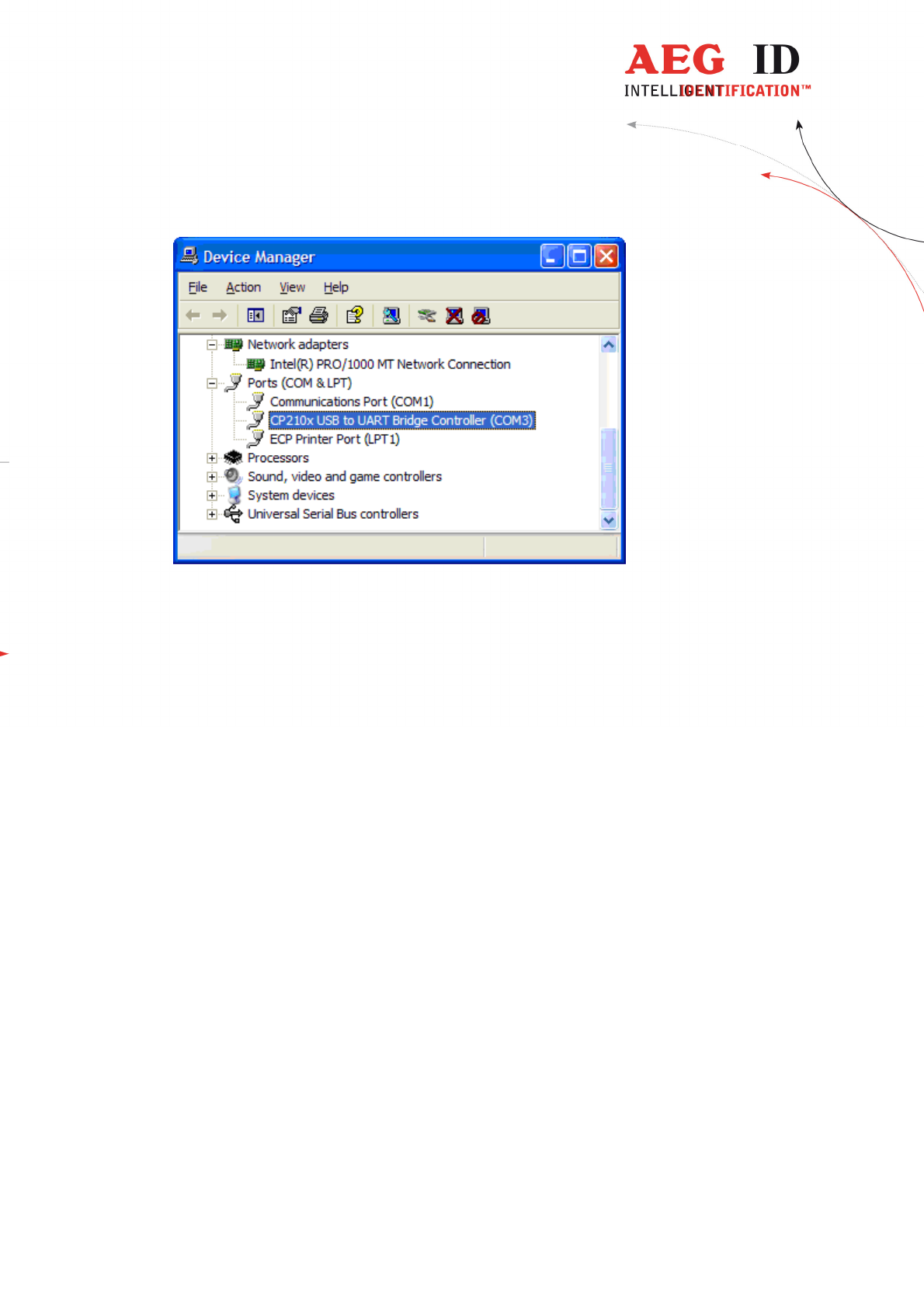
The COM driver for the ARE H9 HF is located under Port (COM & LPT):
„CP2101 USB to UART Bridge Controller (COMx)“
COMx stands for the COM port selected by the driver, this COM port could used
in the software
to communicate with the ARE H9 HF.
In case there is a COM port conflict or another port number is needed, the COM
port number has to be changed.
---------------------------------------------------------------48/51---------------------------------------
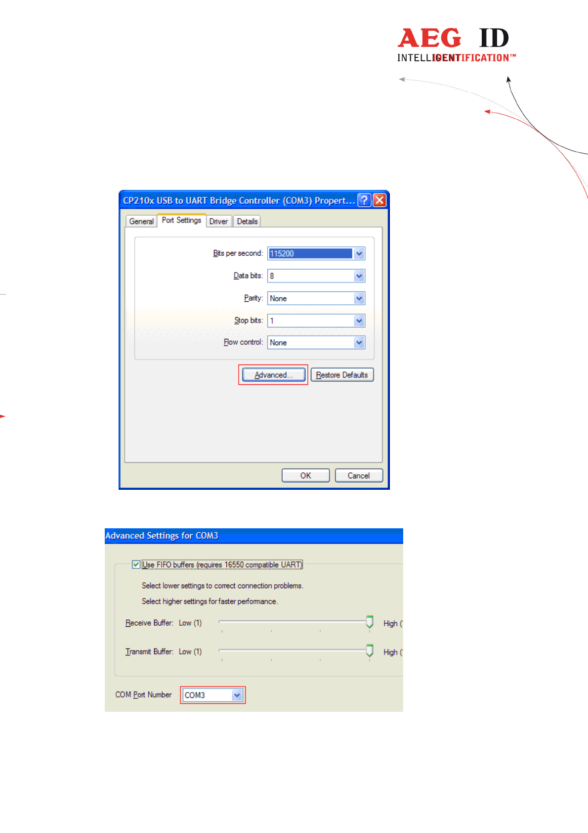
To change the COM port, double click on „Ports (COM & LPT) - CP210x USB
to UART Bridge Controller “.The Properties dialog will open.
Select the „Port Settings“ tab and click on the „Advanced“ button.
Select under „COM Port Number“ the port number to use, then clock „OK“.

---------------------------------------------------------------49/51---------------------------------------
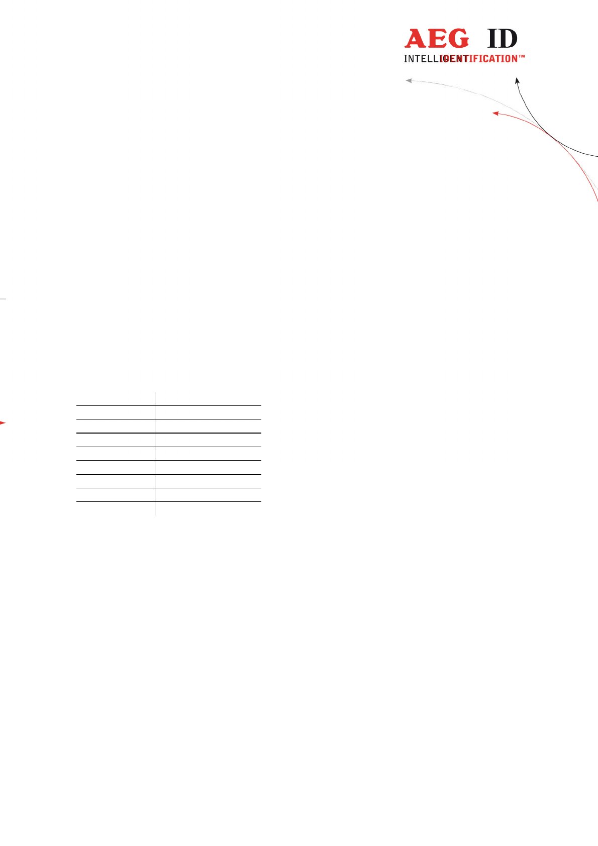
10 Technical specifications
Electrical characteristics
Reading system ISO 14443A, ISO 15693 UID
Operational frequency 13,56 MHz
Display LCD: 2-Zeilen mit 16 Zeichen
Interface USB, USB-HID, Bluetooth, RS232
Power supply 9V Alkali Batterien vom Typ 6LR61
Environment
Storage temperature -10°C bis +70°C
Operation temperature 0°C bis +55°C
Housing protection IP 50
Dimensions
Weight 185 g
Length 135 mm
Width 70 mm
Height 24 mm
Material ABS
11 Operation with other RFID equipment
As there may be electromagnetic interference between different readers, this
reader shall not be operated within a distance of 3m from any other RFID
reader. Otherwise a proper reading result cannot be guaranteed.

---------------------------------------------------------------50/51---------------------------------------
12 Safety instruction
The manufacturer can not be held liable for damages caused by improper use or
abuse, lack of reasonable care, or manipulations contrary to the
recommendations given in this manual.
Do not open the reader! There are several spots inside the device, where high
voltage is generated during the scanning process.
The ARE H9 HF Reader does not contain any parts to be repaired by the user.
Any attempt to open the reader may damage the device. Therefore it may be
repaired only by authorized personal.
Protect the USB interface socket against dirt, moisture and dust.
For cleaning of the reader and cable use a moistened towel. Never use chemical
solvents like e.g. acetone.
Do not submerge the reader in water.
13 FCC Information
Federal Communications Commissions (FCC) Statement
15.21
You are cautioned that changes or modifications not expressly approved by the part
responsible for compliance could void the user’s authority to operate the equipment.
15.105(b)
This equipment has been tested and found to comply with the limits for a Class B digital
device, pursuant to part 15 of the FCC rules. These limits are designed to provide reasonable
protection against harmful interference in a residential installation. This equipment generates,
uses and can radiate radio frequency energy and, if not installed and used in accordance with
the instructions, may cause harmful interference to radio communications. However, there is
no guarantee that interference will not occur in a particular installation. If this equipment
does cause harmful interference to radio or television reception, which can be determined by
turning the equipment off and on, the user is encouraged to try to correct the interference by
one or more of the following measures:
- Reorient or relocate the receiving antenna.
- Increase the separation between the equipment and receiver.
- Connect the equipment into an outlet on a circuit different from that to which the receiver is
connected.
- Consult the dealer or an experienced radio/TV technician for help.
---------------------------------------------------------------51/51---------------------------------------
14 Notification of changes
Ausgabe Datum Beschreibung der Änderung Autor
001 01.10.2014
First revision FW
002 30.04.2015
Mirror Code added
HID left button “carriage return” added
FW
003 09.12.2015
Reader Terminal MM
004 01.04.2016
Orientation ferrite antenna added FW
005 19.05.2016
FCC Information MK
006 22.06.2016
FCC Information correction MK
15 Contacts
To improve our products, as well as its documentation is our permanent effort.
For any questions, feedback or comments please call:
Tel.: ++49 (0)731-140088-0
Fax: ++49 (0)731-140088-9000
e-mail: sales@aegid.de
http:// www.aegid.de