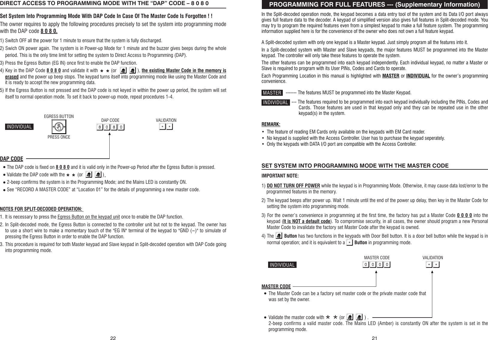
AEI Protect On Systems DA2800 SPLIT-DECODED ACCESS CONTROLLER User Manual

AEI Protect-On Systems Limited SPLIT-DECODED ACCESS CONTROLLER

User Manual

SPLIT-DECODED CONTROLLERFOR DK-2800 SECURITY KEYPADSDA-2800 & DA-2801Installation & Operation ManualFOR ELECTRIC LOCK, INTER-LOCKAND SECURITY SYSTEM INSTALLATIONSVERSION: 10/2010AEI PROTECT-ON SYSTEMS LIMITEDwww.apo-hk.comRoHSComplianceFCC STATEMENT                                                                                                                                                   1. This device complies with Part 15 of the FCC Rules.                              Operation is subject to the following two conditions:(1)This device may not cause harmful interference, and(2)This device must accept any interference received, including interference  that may cause undesired operation.2. Changes or modifications not expressly approved by the party responsible forcompliance could void the user's authority to operate the equipment.
TABLE OF CONTENTSINTRODUCTIONFEATURESSPECIFICATIONSPACKAGE CONTENTSTHE SPLIT-DECODED CONTROLLER UNIT (Figure 1)THE MAIN CIRCUIT BOARD OF THE CONTROLLER --- (Figure 2)INSTALLATIONPrecautionsSplit-Decoded Mode -- (For DA-2800 & DA-2801)The Necessary Connections For Split-DecodedThe Function Mode Jumper Setting For Split-Decoded -- (DA-2800 Only)The Link-Up Jumper & Link-Up Code AcquisitionThe Function Mode Jumper -- (Available On DA-2800 Only)CONNECTION TERMINALSThe Audible & Visible SignalsThe Alarm Outputs & WarningsRF Remote Controller -- (DA-2800 Only)Stand Alone Mode -- (DA-2800 Only)APPLICATION EXAMPLESBasic Wirings of A Split-Decoded Door LockBasic Wirings of An Inter-Lock System Using Two Split-Decoded KeypadsAPPLICATION HINTS FOR THE AUXILIARY TERMINALSPROGRAMMING FOR FULL FEATURES --- (Supplementary Information)Set System in Programming Mode with The Master CodeDirect Access to Programming Mode with The “DAP” Code – 8 0 8 0Refresh The System with The “Refreshing Code” --- 9 9 9 9The Default Values of The KeypadFEATURE PROGRAMMING -- KEY IN AND STORE THE DESIRED VALUESProgramming Criteria for CodesRecord A Master CodeRecord A Super User PINOperation And Functions of The Super User PINRecord The Common User PINs for Output 1, 2 & 3Record-Delete PINs or Cards for Output 1, 2, & 3Examples – Programming And OperationVisitor Codes  (For Output 1 Only)Duress Codes  (For Outputs 1, 2 & 3)The Operation And Function of The Duress CodeConfiguration of The Output Modes for Output 1, 2 And 3Personal Safety And System Lock-Out 2..........................................................................................4..............................................................................................4..........................................................................................5.....................................................................................5............................................................6.................................................6............................................................................................7............................................................................................7.............................................................7...............................................................8.........................................8.............................................................8....................................................9.................................................................................1 0............................................................................1 4..........................................................................1 4...................................................................1 5.....................................................................1 5.................................................................................1 6................................................................1 6.......................................1 7.......................................................1 8.........................................2 1....................................................2 1...........................................2 2..................................................2 3.......................................................................2 3........................................2 4..........................................................................2 4..................................................................................2 5...............................................................................2 5.............................................................2 6.........................................................2 6............................................................2 7...............................................................2 8........................................................................3 0....................................................................3 1.........................................................3 2....................................................3 3...................................................................3 3418 0 Door Forced Open Warning & TimeFUNCTION MODE / TIME:0---OFF1-999 Seconds 80 FUNCTION / TIME #Mode = 0, Door Forced OpenWarning OFF8 1 Propped-up Warning & Time 81 FUNCTION / TIME # Mode = 0, Propped-up Warning OFF9 0 Egress Delay Warning & AlarmCODE 1 - FUNCTION MODE:1---Momentary, No warning2---Momentary, with warning3---Momentary, with warning + Alarm4---Hold Contact, No warning5---Hold Contact, with warning6---Hold Contact, with warning + AlarmCODE 2 - DELAY TIME: 0---No Delay1-99 Seconds90 CODE 1 CODE 2 #Mode = 1 Momentary, No warningTIME = 0No Delay9 1 Door Opening Alarm & TIMERALARM TIME:0---No Alarm1-999 Seconds91 ALARM TIME # Time = 0, No Alarm9 4 Operation Mode & Wiegand OutputMODES OF WIEGAND OUTPUT0---Stand Alone Keypad-Valid Codes & Cards Only1---Reader-All Codes & Cards2---Master Keypad-Valid Codes & Cards only3---Slave Keypad-Valid Codes  & Cards only94 WIEGAND O/P MODE # Mode = 0 Keypad ModeSYSTEM  CODES FUNCTION CODE ENTRY RESULTS0 0 0 0Factory Set Master Code for  User  to  set  system  in programming Mode at the first time.THIS IS NOT A PERMANENT SYSTEM CODE & IT IS CHANGED IF A NEW MASTER CODE IS PROGRAMMED.0000 * *OR NEW MASTER CODE   * *System in Programming Mode9 9 9 9REFRESH  CODE  --  Refresh the system and set all its function back to default values.9999 # All programmed data are cleared and back to the default values except the Master Code8 0 8 0DAP CODE-- Direct access to programming mode. Valid only in the power-up delay period8080 # System in Programming Mode0 9 9 9USER PINs / Codes / Cards whole group clearance Code - Key in the Code to clear all the users in the LocationLOCATIONS:10--- User Group 120--- User Group 230--- User Group 340--- Vistor Group41--- Duress Group 142--- Duress Group 243--- Duress Group 3 LOCATION NO.   0999 # Whole group of users in the selected location are cleared* * Exit Programming Code ** The system back to normal opration after programming
3User PIN Entry ModePacifier Tones On-Off SelectionOutput Operation AnnouncerStatus LED Flashing On-Off during StandbyDoor Forced Open Warning & TimingDoor Propped-Up Warning & The Delay TimeIntelligent Egress Button – An Unique Feature of A Contemporary KeypadWhere And Why “Going Out” Needs AttentionEgress Delay , Warning And AlarmConfigurations of The Egress Warning And AlarmDoor Opening Alarm & TimerClose The Programming ModeThe Operation Modes and The Wiegand Output Wiegand Output at Keypad Operation ModePROGRAMMING SUMMARY CHART --- (Supplementary Information)...................................................................................3 4..........................................................................3 4.............................................................................3 4.................................................................3 5.....................................................................35..............................................................3 5.......................................3 6.............................................................3 6........................................................................3 7.........................................................3 7.............................................................................3 8...........................................................................3 8..............................................................3 9..............................................................3 9............................................4 040THE PROGRAMMING SUMMARY CHART --- (Supplementary Information)LOCATION FUNCTION ENTRY LIMITS & CODE OPTIONS CODE ENTRY FACTORY DEFAULT0 1 Master Code 4-8 Digits 01 MASTER CODE # NIL0 2 Super User PIN 4-8 Digits 02 SUPER USER PIN # NIL0 3 Common User PIN for O/P 14-8 Digits03 COMMON USER PIN 1 # NIL0 4 Common User PIN for O/P 2 04 COMMON USER PIN 2 # NIL0 5 Common User PIN for O/P 3 05 COMMON USER PIN 3 # NIL1 0 User PINs / Cards for O/P 1CODE 1 - MEDIA:1---EM Card2---Private User PIN3---EM Card+Sec User PIN4---EM Card+Com User PIN5---Deletion of User PINCODE 2 - USER ID:000-999---Group 1(10)001-100---Group 2(20)001-100---Group 3(30)CODE 3 - USER PINs / Cards:4-8 Digits / Cards10 CODE1 CODE2 CODE3 #NIL2 0 User PINs / Cards for O/P 2 20 CODE1 CODE2 CODE3 #NIL3 0 User PINs / Cards for O/P 3 30 CODE1 CODE2 CODE3 #NIL4 0 Visitor Codes CODE 1 - VISITOR ID: 01-50CODE 2 - VALID PERIOD: 00---One Time01-99 HoursCODE 3 - VISITOR CODE: 4-8 Digits40 CODE1 CODE2 CODE3 #NIL4 1 Duress Code for O/P 1 CODE ID - O/P 1: 01-50CODE ID - O/P 2: 01-10CODE ID - O/P 3: 01-10DURESS CODE: 4-8 Digits41 CODE ID DURESS CODE # NIL4 2 Duress Code for O/P 2 42 CODE ID DURESS CODE # NIL4 3 Duress Code for O/P 3 43 CODE ID DURESS CODE # NIL5 1 O/P Mode for O/P 1 OUTPUT MODE & TIME:0--- Start / Stop1---99999 Seconds, Momentary51 O/P MODE & TIME # 5 Seconds5 2 O/P Mode for O/P 2 52 O/P MODE & TIME # 5 Seconds5 3 O/P Mode for O/P 3 53 O/P MODE & TIME # 5 Seconds6 0 Personal Safety & Lock-outLOCK-OUT CODE:1---10 Trial, Lock-out 60 Sec.2---10 Trial, Activates Duress5-10---5-10 Trial, Lock-Out 15 Minutes00---No Lock-out60 LOCK-OUT CODE #Code = 1, 10 Trials, Lock-out 60 Seconds7 0 PIN Entry ModeENTRY MODE:1---Auto Mode2---Manual Mode70 ENTRY MODE # Mode = 2, Manual  Mode7 1 Pacifier Tone ON-OFFFUNCTION MODE:0---OFF1---ON71 FUNCTION MODE # Mode = 1, Pacifier Tone ON7 2 Output Announcer 72 FUNCTION MODE # Mode = 1 Announcer ON7 3 Standby LED Flashing 73 FUNCTION MODE # Mode = 1, Flashing On
INTRODUCTION                                                                                                                                                   The DA-2800 or DA-2801 is a self-contained access controller. It has been designed mainly as the decoder unit working together with the keypads in the DK-2800 series to make up a split-decoded keypad system. In split-decoded operation the system provides full Tri-Tech features of accepting EM Card, PIN/Code and RF Remote Control. This unique design philosophy makes the system to provide high level of security in preventing sabotage far ahead of the traditional stand alone keypad systems.The DA-2800 also has been designed to work stand alone without keypad. The three relay outputs can be controlled by the RF remote control key directly. The Output 1 operates in Start/Stop mode or in Momentary mode with the built-in adjustable timer for door strike. The Output 2 and 3 operate in Start/Stop mode and manually controlled Momentary mode respectively.DA-2801 is the simplified version without the RF remote control function. It is solely a full feature decoder of the DK-2800 series keypads in Split-decoded operation.The DA-2800 or DA-2801 has three output relays and a built-in door chime. It is an ideal device for Door Strike, Alarm Arm-disarm control and actuation of Automatic Operator, such as garage door opener.The keypad system with the DA-2800 or DA-2801 decoder in Split-decoded operation offers full features performance even the keypad is just a simplified version. Maximum three keypads can be connected in parallel to the decoder unit with one of them setting in master mode and the other two setting in slave mode. Each keypad can be programmed with its own PINs and Cards. The slave keypads take the features and the functions programmed in the master keypad to operate the system. The decoder interprets the data and operates the desired functions faithfully.FEATURES                                                                                                                                                   DA-2800 – Full Feature Decoder + RF Remote ControlDA-2801 – Full Feature DecoderI) DA-2800 & DA-2801•  A Decoder for The DK-2800 Series Keypads in Split-decoded Operation•  Decodes The Data of EM Cards, PINs / Codes & Functions Faithfully from Keypads•  Provides Full Features in Split-Decoded Mode for Any Keypad in The DK-2800 Series•  Simple Three Wires Connection to Keypads For Data Communication, (+), (-) & Data I/O•  Easily to Set Up Link Up Code with The Keypads And The Decoder•  Three Independently Controlled Output Relays•  Built-in Door Chime•  Built-in Alarm for Tamper, Door Forced Open and Door Opening in Split-Decoder Mode•  Built-in Current Limited (750mA) Power Source for The Keypads to Prevent Sabotage of Short Circuit from OutsideII) DA-2800 Only•  Provides The Tri-Tech Features of RF Remote Control, Card and PIN/Code Reading in One System•  24 bits Self-learning Codes (over 1 million codes) for The RF Remote Control Keys•  Accepts 40 RF Remote Control Keys Maximum•  4 RF Remote Control Channels for Stand Alone or Split-decoded Operation•  Remote Control Key Controls Output 1, 2, 3 & Door Chime4CLOSE THE PROGRAMMING MODE                                                                               ( * * )                                                                                                                                                   Always close programming mode with * * to set system back to normal Operation after programming.The         button is equivalent to the * button in the keypad with bell button.VALIDATION ** ---------------  System is back to normal operation modeTHE OPERATION MODES AND THE WIEGAND OUTPUT                                 (Location 94)                                                                                                                                                   Four operation modes are available for the selection. The codes are 0, 1, 2 and 3.WIEGAND OUTPUT AT KEYPAD OPERATION MODE0 --- Stand Alone Keypad Mode -- (Default)The system provides full functions to operate its outputs and at the same time provides Wiegand Data Output for all the VALID Cards and User PINs including the Duress Codes and Visitor Codes. No Wiegand Data Output for the invalid PINs and Cards.1 --- Card & Code Reader ModeIn the Card & Code Reader Mode, the keypad provides Wiegand Data Output for all the Card readings and PINs/Code entries but does not operate its outputs. It is solely a card and code reader.NOTE: It is suggested to clean all the codes, PINs and cards that were previously stored in the system before setting the system for reader mode.2 --- Master Keypad of Split-Decoded Mode (The Only Mode will Send Out the Link-up Code)The keypad unit provides the Wiegand Data Output for the valid user PINs, Codes and Cards exactly like in the Stand Alone Mode. The Master keypad will transfer all the programmed feature data (except the user PINs, Codes and Cards data) to the Access Controller (decoder) right after it exits the programming mode. A Split-decoded keypad system needs at least one Master keypad and one Access Controller to work.3 --- Slave Keypad of Split-Decoded ModeThe Keypad unit provides the Wiegand Data Output for the valid user PINs, Codes and Cards exactly like in Stand Alone Mode. No feature data is transferred to the Access Controller (decoder) from the Slave keypad. It takes the same feature data from the Master keypad to operate. The Slave keypad(s) is for a Split-Decoded system that needs more than one keypads for operation convenience.NOTE:a) Do not set more than one keypads in Master mode in a Split-Decoded system. Otherwise, the data will be confused.b) Each keypad in Split-Decoded mode can be programmed independently with its own user PINs, Codes and Cards. The PINs, Codes and Cards can be repeatedly used in other keypads in the same system.OPERATION MODELOCATION VALIDATION#0 , 1 , 2 or 39439.INDIVIDUALINDIVIDUAL
SPECIFICATIONS                                                                                                                                                   Operating Voltage:   12V-24V DC, Auto AdjustingOperating Current:   65mA (quiescent) to 100mA (three relays active)Operating Temperature:   -20  C to +70  CEnvironmental Humidity:   5-95% relative humidity non-condensingThe Adjustable Timer for Output 1:   1-30 SecondsPower Up Delay:  5 SecondsTamper Alarm:  3 MinutesInput Sensing Terminals:   a) Door position, b) Egress, c) O/P 1 Inhibit, d) Door Bell, e) TamperOutput Control Terminals:  a) Duress, b) Alarm, c) Key Active, d) Inter-lock;  Transistor Open Collector, 24VDC/100mA sink MaxOutput Contact Ratings: Output Relay 1 – N.C. & N.O. dry contacts, 5A/24VDC Max. Output Relay 2 – N.C. & N.O. dry contacts, 1A/24VDC Max. Output Relay 3 – N.C. & N.O. dry contacts, 1A/24VDC Max.Dimensions:   32.5(H) X 120(W) X 87(D)mm Plastic BoxWeight:   250g netRF Remote Controller (DA-2800 Only) : Number of Self-leaning Codes : Over 1 MillionNumber of RF Control Keys : 40 Maximum4 Control Channels : Output 1, 2, 3 & Door ChimeOperation Frequency : 433.92MHzControl Distance : 60 Meters Approx. in Open SpaceReceiver Type : Super-heterodyneOperation Voltage : 12V Alkaline Battery, Type 27A (Battery Not Included)Weight : 32gSpecifications are subject to change for modification without noticePACKAGE CONTENTS•  One Access Controller•  One Pack of Mounting Screws•  Two RF Remote Control Keyfobs (DA-2800 Only), Battery Not Included•  One Owner’s Manual5EXAMPLES:Example 1: Set Egress Button in Momentary contact 5 seconds with delay & warning beep90  2  5  #      (a)             (b)           (c)          (d)  (a) Egress function programming, (b) Momentary contact with warning, (c) Delay time of 5 seconds to release door, (d) Entry confirmationExample 2: Set Egress Button in Holding contact of 10 seconds with warning beep90  5  10  #      (a)             (b)              (c)             (d)  (a) Egress function programming, (b) Holding contact mode with warning, (c) Holding time of 10 seconds to release door, (d) Entry confirmationExample 3: Set Egress Button in Momentary contact without delay (This is the default setting)90  1  0  #      (a)             (b)           (c)          (d)  (a) Egress function programming, (b) Momentary contact without delay, (c) Release door instantly, (d) Entry confirmationDOOR OPENING ALARM & TIMER                                                                        (Location 91)                                                                                                                                                   ALARM & TIMING OF DOOR OPENING0 --- No Alarm – (Default)The Alarm Output is disabled1 – 999 --- Alarm TimerThe Door Open Alarm operates the Alarm Output (Terminal 13) only. It is mainly prepared to trigger an optional alarm system. Put any Timing Figure of 1 to 999 into the box to enable the function of the Door Opening Alarm. The figure is the time in second of the alarm duration, which starts to count after the door is opened and it resets automatically when the time reaches.The alarm can be stopped with the User Codes/Cards or the Super User PIN for Output 1 at any time before the end of the alarm time.NOTE: The Door Opening Alarm is designed to protect the emergency exit door from use by the un-authorized person. The alarm occurs when the door is opened or forced to open. However, Alarm will not happen if the door is opened with a valid User Code or Card.The Manner of The Door Opening Alarm:a) The door is forced to open without using PIN/Card – Alarmb) The door is opened with Egress Button – Alarmc) The door is opened with PIN/Card – No AlarmTo prevent confusion of the alarm outputs. It is suggested to disable the "Door Forced Open Warning" at Location 80 while "Door Opening Alarm" function is enabled. If both functions at Location 80 and Location 91 are enabled and are set with different timings, the system will combine them and will take the longer one for alarm time.ALARM TIME VALIDATIONLOCATION0 or 1 - 99991 #38MASTER
THE SPLIT-DECODED CONTROLLER UNIT (Figure 1)THE MAIN CIRCUIT BOARD OF THE CONTROLLER --- (Figure 2)NOTE:  Factory suggest that the work of timer adjustment and change of jumper settings on the main circuit board are to be done by the Installer only.No adjustment/setting change is required for Split-decoded operation with the ex-factory settings.6LINK-UP JUMPEROFF-->ON-->OFFCODE LEARNING BUTTON(DA-2800 ONLY)REMOTE CONTROL SIGNAL & STATUS (DA-2800 ONLY)INTERNAL SIREN & DOOR CHIMECONNECTION TERMINALSMAINSOUTPUT BEEP JUMPER ON OR OFFFUNCTION MODE JUMPER1. SPLIT-DECODED2. STAND ALONE MODE 13. STAND ALONE MODE 2ADJUSTABLE TIMER FOR OUTPUT 1TURN CLOCKWISE FOR MAXIMUM TIMERECEIVER FOR REMOTE CONTROL(DA-2800 ONLY)EGRESS DELAY , WARNING AND ALARM                                                           (Location 90)                                                                                                                                                   CONFIGURATIONS OF THE EGRESS WARNING AND ALARMKey in the number to enable 1 of the 6 configurations described below:1 --- Momentary Contact Mode without Warning -- (Default)• Press the Button once. No warning or alarm is given during Egress Delay.• Good for silent area. The people have to wait for the door open until the delay time reaches.2 --- Momentary Contact Mode with Warning Beep• Press the Button once. The system gives Warning Beeps during the Egress Delay.• Good for the place required attention. The keypad beeps during the people are waiting for the door open.3 --- Momentary Contact Mode with Warning Beep & Alarm• Press the Button once. The system gives Warning Beeps and also activates its Alarm O/P during the Egress Delay• Good for door for the authorized people only. The keypad beeps and report alarm to a security system during the people are waiting for the door open. • This is usually an “Emergency Exit”. The door can be opened with the Keypad without triggering of the Buzzer and Alarm Output.4 --- Holding Contact Mode without Warning• Press and hold the Button. No warning or alarm is given during the Egress Delay.• Good for the silent area. The people require to press & hold the button until the delay time reaches for the door open.5 --- Holding Contact Mode with Warning Beep• Press and hold the Button. The system gives Warning Beeps during Egress Delay.• Good for the place required attention. The keypad beeps while the button is kept pressed during the people are waiting for the door open.6 --- Holding Contact Mode with Warning Beep & Alarm• Press and hold the Button. The system gives Warning Beeps and also activates its Alarm O/P during Egress Delay.• This is usually an “Emergency Exit”. The door can be opened with the Keypad without triggering of the Warning and Alarm.EGRESS DELAY TIMER0 --- No Delay – (Default)Output 1 activates instantly (the door is released instantly) when the Egress Button is pressed.1 – 99 --- Egress Delay TimingPut any number of 1 to 99 into the box to enable the Egress Delay. The number is the time in second, which starts to count when the Egress Button is pressed. Output 1 activates (the door is released) when the delay time reaches.NOTE:1) Momentary Contact -- The Egress Delay starts to count when the egress button is momentarily pressed. Output 1 activates automatically (door is released) when the delay time reaches.2) Holding Contact -- The user MUST hold the egress button in contact for the whole period of the Egress Delay time until Output 1 activates. If the egress button is released before the end of the Egress Delay, the timer will stop to count and reset.3) The Egress Delay does not affect the operation of the User PINs/Cards for Output 1. The User PINs/Cards always give INSTANT action.Examples: (please see the following page)FUNCTION MODES VALIDATIONDELAY TIMELOCATION1 - 6 0 or 1 - 99 #9037MASTER
INSTALLATION                                                                                                                                                   PRECAUTIONS1) Installation Location:The built-in receiver of the Access Controller is working at the UHF frequency band of 433.92MHz. To get the best receiving result of the signals from the remote keys a correct installation location is necessary.i) Install it on a location inside the house facing to the open space and there has no strong electro-magnetic wave signals near it. ii) Do not install it in a concrete room or under a concrete stair, which shortens the control distance.2) Prevent Accidental Short Circuit:In the previous experience, most of the damages caused in the installation are accidental touching of the components on circuit board with the wires carrying power. Please be patient in the installation. Study the manual to become familiar with the specifications of the system beforehand is also important.i) Do not apply power to the system while it is in installation.ii) Check carefully all the wirings are correct before applying power to the system for testing.SPLIT-DECODED MODE -- (for DA-2800 & DA-2801)Split-decoded Mode needs at least one keypad to work with the decoder. The decoder decodes all the commands from the keypad to operate its outputs. It is an unique solution to immediately up-grade a general purpose keypad to a high security access control system. All the keypads in the DK-2800 series with Data I/O Port are compatible with the decoder. A Split-decoded system divides itself into the outside keypad unit and the inside decoder unit. Any sabotage to the outside unit does not affect the security of the inside unit.7RF WIRELESSREMOTE CONTROL (DA-2800 ONLY)DOOR LOCK (OUTPUT 1)SECURITY SYSTEM (OUTPUT 2)AUTOMATICOPERATOR (OUTPUT 3)COMMON GROUNDCOMMON GROUNDDA-2800 OR DA-2801SLAVE 1SLAVE 2MASTERDATA I/OCOMMON GROUNDDATA I/ODATA I/OMAXIMUM 3 KEYPADS CAN BE CONNECTED IN PARALLELINTELLIGENT EGRESS BUTTON – AN UNIQUE FEATURE OF A CONTEMPORARY KEYPAD                                                                                                                                                   Most of the keypads for access control are just for controlling of “Going In” from outside. It is not enough for today’s access control systems. In fact, controlling of “Going Out” is also very important in many public passage areas. They are not allowed to use locks or digital keypads for stopping of “Going Out” due to safety reasons. Such as hospitals, kindergartens, elderly homes, convenient stores, emergency exits etc.. The wardens, teachers, shopkeepers and the guards are always required to keep an eye on people to prevent unattended leaving, shoplifting, and illegal use of the emergency exits.The Intelligent Egress Button can be programmed to do something to get the attention of the person on duty before the door is opened. The button offers programmable egress delay, delay with warning, holding button required for the delay, momentary button contact with warning for the delay and even gives alarm when a controlled door is opened.Locations 90 and 91 below are the places for setting the desired functions for the Egress Button.The functions programmed to the Egress Button do not affect the normal operation of the system with its keypad. For the safety consideration, the operation of the keypad with PIN, Code or Card is always in the first priority to give instant action to the output relay 1 for door strike.It is NOT required to program the Egress Button with the special function in normal use. Just leave it on its default values.WHERE AND WHY “GOING OUT” NEEDS ATTENTIONExamples for some areas may need an Intelligent Egress Button:Hospital:Some of the patients are not allowed to leave the ward without doctor’s permission. An egress button with exit delay and warning beeps will help the nurse or warden to get the attention to the door when the egress button is pressed. Further setting of the egress button with holding contact for the delay even gives higher level of security to a controlled door.Kindergarten:Young children are always active. Some of them may be willing to go out to explore their ways of playing. For safety reason, teachers have to watch all of them in the attended area. Leaving school alone without the companion of parents or teacher is dangerous to the young children. An egress button with delay and warning beeps will be helpful to prevent the children trying to go out without getting the attention of the teacher.Elderly Home:Elderly needs constant attention and care. Some old people have poor memory. They may forget the way to come back if they leave home alone. An egress button with delay and warning beep will easily get the attention of the warden before the door is open.Convenient Store:Most of the convenient stores have just only one or two shopkeepers on duty. They are usually the cashier. Shoplifting may easily happen while the shopkeeper is busily serving customers at the cashier desk. A holding contact egress button with delay and warning beeps may help to stop most of the shoplifting. As the thief knows that he is gotten attention by the shopkeeper before the door is open.High Traffic Passage:A short buffer time may be necessary for opening a door outward after pressing the egress button for those exits open to a high traffic passage. An egress button with short delay and warning beeps helps the user to pay attention to the people passing by to prevent hitting them when the door is pushed outward.Emergency Exit:Emergency Exit is not open to the public for daily use. It is for emergency case only. It is usually closed and watched by the security guards. The egress button of this keypad can be programmed to offer exit delay with warning beeps and even gives alarm output to trigger an alarm system when the door is forced to open or the door is open after the exit delay expired. It is an useful tool to get the attention of the person on duty.36
THE NECESSARY CONNECTIONS FOR SPLIT-DECODED                                                                                                                                                                                             1) Connect the Data I/O ports of the Decoder (Terminal 4) and the Keypad with wire to link-up the communication ofthe two units.2) Connect the Keypad PWR terminal of the Decoder (Terminal 3) to the keypad power input terminal, which suppliespower to the keypad unit with current limit protection.3) Connect the Common (-) Ground (Terminal 2 or 11) to the (-) ground of the keypad unit to make up the return pathfor the data and the power source.4) Make all other installation connections to the decoder unit, but not to the keypad unit in Split-Decoded Mode. Thesystem provides full feature from the decoder unit according to the functions programmed in the keypad.THE FUNCTION MODE JUMPER SETTING FOR SPLIT-DECODED -- (DA-2800 ONLY)                                                                                                                                                                                             NOTE: No Function Jumper setting is required for the DA-2801. It is fixed in Split-Decoder mode.1) Put the “Function Mode Jumper” to position “1” for Split-Decoder. (It is an Ex-factory Setting)a) The Function Jumper of the DA-2800 has been put on Position 1 at the factory. Setting of the jumper is usually not necessary unless it has been changed. Always put jumper on position “1” for Split-decoded mode.b) The Function Jumper is located on the Main Circuit Board inside the box. Change the setting for Stand Alone mode is required. See Figure 2.2) Set the “Link-up Jumper” from OFF to ON position to enable the link-up of acquiring the link-up code from the keypad (same as the Master Code of the keypad). a) The Jumper is located on the main circuit board inside the terminal compartment. See Figure1.b) The Decoder executes link-up Only Once. The Link-up execution is done when the keypad exits from Programming Mode after pressing **. Put the jumper back to OFF position after link up.c) After the decoder knows the link-up code (Master Code) of the keypad it is not necessary to repeat the link-up procedure in feature change programming except change of the Master Code.Remark:a) All the keypads going to link up with the decoder MUST be with the same Master Code which is the authorization code to enable the data communication between the keypads and the decoder.b) It is not necessary to repeat the link-up procedures for the slave keypads with the same Master Code. Just simply connect them in parallel with the master keypad.c) The decoder will refuse other keypads that are not in the same Master Code to link up with it.d) The failed keypads in the link-up will generate warning beeps.THE LINK-UP JUMPER & LINK-UP CODE ACQUISITION                                                                                                                                                                                       To acquire the link-up code (same as the Master Code) from the Master keypad for Split-Decoded operation is necessary. At any time, when you operate a new Master keypad at the first time it is necessary to let the decoder unit to know the Master Code of the keypad. Otherwise, the decoder can not recognize the data from it. If more than one keypads are going to link up with the decoder, all the keypads are required to have the same Master Code and repeat link-up is not necessary.The decoder executes Link-up Acquisition Only Once at the moment after setting of the Master Keypad to exit Programming Mode with **. 8STATUS LED FLASHING ON-OFF DURING STANDBY                                        (Location 73)                                                                                                                                                   STANDBY FLASHING ON-OFFSome people find the flashing light of the status LED (the amber LED) is annoying during the keypad is on standby, especially at the night time. The standby flashing can be ON-OFF with the setting here.1 --- Standby Flashing ON -- (Default)The Status LED gives Standby Flashing all the time during the keypad is on standby. It also gives all the light indications showing the operation status of the system.0  --- Standby Flashing OFFThe Standby Flashing is disabled but it does not affect the system status indications. All the light indications from it are unchanged.DOOR FORCED OPEN WARNING & TIMING                                                       (Location 80)                                                                                                                                                   DOOR FORCED OPEN WARNING ON-OFF & TIMINGThe Door Forced Open Warning function requires a Door Position Sensing switch (usually a magnetic contact) to work with. Once a Timing Figure is put into the Function Mode box, the warning mode is enabled.0 --- Door Forced Open Warning OFF – (Default)1 - 999 --- Door Forced Open Warning & Alarm ON & TimingThe Timing Figure for the Warning can be 1-999 seconds. The keypad generates the door forced open warning beeps and activates the alarm output (Terminal 13) instantly if the door is forced to open without a valid User PIN/Card or pressing of the Egress Button. The beeps and alarm will last as long as the time set on the timer and it can be stopped at anytime with an User PIN/Card in Group 1 before the end of the time.The Manner of The Door Forced Open Warning:a) The door is forced to open (without using PIN/Card or Egress Button) – Warning & Alarmb) The door is opened with PIN/Card – No Warning or Alarmc) The door is opened with Egress Button – No Warning or AlarmDOOR PROPPED-UP WARNING & THE DELAY TIME                                         (Location 81)                                                                                                                                                   DOOR PROPPED-UP WARNING ON-OFF & TIMINGIf somebody opened the door and it is left open longer than the allowable delay time, the keypad will generate door propped-up warning until the door is re-closed. There is warning beeps from the keypad only but does not activates the alarm output.0 --- Door Propped-up Warning OFF – (Default)1 - 999 --- Door Propped-up Warning ON & The Delay TimeThe Delay Time can be 1 to 999 seconds. It is the time allows the door to open without starting of the warning.FUNCTION MODESFUNCTION MODESVALIDATIONVALIDATIONLOCATIONLOCATION0 or 1 - 9990 or 1 - 999##8081FUNCTION MODES VALIDATIONLOCATION1 or 0 #7335MASTERMASTERINDIVIDUAL
9Example – Change of the Link-up Code ( The Master Code of the Master Keypad)a) Put the Link-up Jumper of the Decoder from OFF to ONOFF           ONb) Set the Master Keypad to Programming ModeEXISTING MASTER CODE     *     *c) Set a New Master Code to the Master KeypadNEW MASTER CODE     #d) Set the Master Keypad to exit from Programming Mode*     *e) The Link-up in the system is done automaticallyBEEP     BEEP  ----- From Keypadf) Put the Jumper back to OFFON           OFFg) The system is in Split-decoded operation with the new Link-up CodeTHE FUNCTION MODE JUMPER -- (AVAILABLE ON DA-2800 ONLY)                                                                                                                                                                                             Three positions are available for the Function Mode Jumper. Position 1 is for Split-decoded Mode and the positions 2 & 3 are for Stand Alone Modes.POSITION 1 – SPLIT-DECODER (MAINS LED LAMP FLASHING)Position 1 is for Split-decoder mode. All the functions and the 3 output relay operation manners follow the programmed settings in the Master keypad. All the functions of the decoder are programmable from the keypad unit. The DA-2800 system is controlled by the keypads and the remote control keys in the Split-decoded mode.POSITION 2 – STAND ALONE MODE 1 – START / STOP FOR OUTPUT 1  (MAINS LED LAMP ON)Position 2 is one of the settings for Stand Alone mode. All the three Output Relays are controlled by the RF Remote Key with the following functions:Output 1 – Start / Stop – Controlled by Channel 1 of the RF remote key. Press the Button A once to start and press thebutton once again to stop.Output 2 – Start / Stop – Controlled by Channel 2 of the RF remote key. Press the Button B once to start and press the button once again to stop.Output 3 – Manual Momentary – Controlled by Channel 3 of the RF remote key. The output relay operates (Starts) as long as the Button C is pressed and it stops when the button is released.POSITION 3 – STAND ALONE MODE 2 – ADJUSTABLE TIMER FOR OUTPUT 1  (MAINS LED LAMP ON)Position 3 is one of the settings for Stand Alone mode. All the three Output Relays are controlled by the RF Remote Key with the following functions:Output 1 – Adjustable Timer – Controlled by Channel 1 of the RF remote key. Press the Button A once to start the timer and it resets automatically after time out. It is adjustable 1-30 seconds. It is convenient for setting the time for door strike. Turn the timer clockwise for maximum time. See Figure 2.Output 2 – Start / Stop – Controlled by Channel 2 of the RF remote key. Press the Button B once to start and press the button once again to stop.Output 3 – Manual Momentary – Controlled by Channel 3 of the RF remote key. The output relay operates (Starts) as long as the Button C on the remote key is pressed and it stops when the button is released.ENTRY MODES VALIDATIONLOCATION1 or 270 #USER PIN ENTRY MODE – Auto or Manual                                                          (Location 70)                                                                                                                                                   USER PIN ENTRY MODESTwo modes 1 and 2 are available for User PIN entry options. The EM Card is always in Auto Entry Mode and is not affected by the selection here.1 --- Auto Entry ModeAuto Entry Mode requires no pressing of the # key following the User PIN for code checking. In the Auto Entry Mode, the User PINs MUST be set in the same digit length of the Master Code (For example, if the Master Code is 5 digits, then all User PINs must be in 5 digits as well. All other User PINs not in 5 digits become invalid). When the number of digits reaches, the system will check the User PIN automatically. Good for high traffic access control.2 --- Manual Entry Mode – (Default)Manual Entry Mode always requires the # key following of the User PIN for code checking. The User PINs can be 4-8 digits arbitrary and they are NOT required to be in the same digit length of the Master Code. Manual Entry increases the level of security in the code trial by the unauthorized people.PACIFIER TONES ON-OFF SELECTION                                                               (Location 71)                                                                                                                                                   PACIFIER TONES ON-OFF MODESThe Pacifier Tone is the Beep Tones from the keypad, which include the tones of Successful Key entry (1 beep), the Output Operation Announcer (2 beeps or 1 long beep) and the Unsuccessful User Code/Card entry (5 beeps). NOTE :The beeps for the Warning and the Power-up Delay do not belong to pacifier tones and can not be set to OFF.1 --- Pacifier Tone ON – (Default)All the Pacifier Tones available from the keypad are enabled. They are the response tones indicating the operation status of the keypad after the Card/User Code is entered.0 --- Pacifier Tone OFFAll the Pacifier Tones are OFF. Good for place needs for a silent environment.OUTPUT OPERATION ANNOUNCER                                                                     (Location 72)                                                                                                                                                   OUTPUT OPERATION ANNOUNCERThe announcer gives notification beep to the users and the visitors on the operation status of the outputs. There are two notification modes available for the selection.The notification is also OFF while the Pacifier Tone OFF mode in the Location 71 is selected.1 --- 1 Second Long Notification -- (Default)1 second notification beep is given when the output relay is activated with a valid Card/Code or Egress Button. It is prepared to notify the person outside the door when the lock is released and the door can be opened. It is good for the door lock device gives no sound when it activates, such as a magnetic lock.0 --- 2 Short Beeps Notification2 short beeps notification is given when the output is activated with a valid Card/Code.FUNCTION MODES VALIDATIONLOCATIONFUNCTION MODES VALIDATIONLOCATION1 or 01 or 0##717234INDIVIDUALINDIVIDUALINDIVIDUAL
10CONNECTION TERMINALS                                                                                                                                                   NOTE:DRY CONTACTA dry contact means that no electricity is connected to it. It is prepared for free connections. N.C.Normally Closed, the contact is closed circuit at normal state. It is open circuit when active.N.O.Normally Open, the contact is open circuit at normal state. It is closed circuit when active.TRANSISTOR OPEN COLLECTOR OUTPUTAn open collector output is equivalent to a Normally Open (N.O.) contact referring to ground similar to a relay contact referring to ground. The transistor is normally OFF, and its output switches to ground (-) when active. The open collector can only provide switching function for small power but it is usually good enough for controlling of an alarm system. The maximum rating is 24V DC/100mA SinkOPEN COLLECTOROUTPUT ----Output switches toground when activatedN.O. CONTACTOUTPUT ----Output switches toground when activatedEQUIVALENT- ALARM O/P- KEY ACT O/P- N.O.- COM- N.C.- N.O.- COM- N.C.- N.O.- COM- N.C.- TAMPER- GND(-)- DOOR SENS- O/P 1 INHIB- INT. LOCK- DU OUT- DOOR BELL IN- EG IN- DATA I/O- KEYPAD PWR- GND(-)- 12-24V DCOPEN COLLECTOR OUTPUTOPEN COLLECTOR OUTPUT1A RELAY DRY CONTACTSFOR AUXILIARY CONTROL1A RELAY DRY CONTACTSFOR AUXILIARY CONTROL5A RELAY DRY CONTACTSFOR DOOR STRIKEOPEN COLLECTOR OUTPUTOPEN COLLECTOR OUTPUTINPUT/OUTPUT FOR SPLIT-DECODED SIGNALSPOWER OUTPUT FOR KEYPADSCOMMON GROUNDPOWER INPUT FOR SYSTEMN.C. SWCOMMON GROUNDN.C. SWN.O. SWN.O. SWN.O. SWOUTPUT 1O UTPUT 2O UTPUT 3CONFIGURATION OF THE OUTPUT MODES OF OUTPUT 1, 2 AND 3    (Locations 51, 52 & 53)                                                                                                                                                   The three relay outputs of this keypad are programmable for Start/Stop or Timing modes. Apart from the door access control, alarm arm-disarm control, they are also universal timers for automatic operators in industry with their 99,999 seconds (over 24 hours) programmable timer.OUTPUT LOCATIONS 51 -- Location for Output 152 -- Location for Output 253 -- Location for Output 3OUTPUT MODE & TIMING 0 – Start /Stop Mode (Toggle)The number 0 sets the output to the Start / Stop mode. The output Starts when an User PIN and/or Card is entered/read; the output Stops when an User PIN and/or Card is entered/read again.1-99999 Seconds Momentary --- (Default -- Momentary 5 Seconds)The output can be set in Momentary Mode with the time of 1 second to 99,999 seconds. The output will reset automatically when the time expires OR it can be RESET manually at anytime with the Super User Code that operates the desired output before the end of the time.Example :  Reset Output 1 --                     # 1 ------------- Output 1 resets                  Reset Output 2 --                     # 2 ------------- Output 2 resets                  Reset Output 3 --                     # 3 ------------- Output 3 resetsPERSONAL SAFETY AND SYSTEM LOCK-OUT                                                   (Location 60)                                                                                                                                                   SAFETY & LOCK-OUT OPTIONSThe Options are represented by their Mode Numbers in programming. They are described below:1 --- After 10 successive false Card/User Code trials, the keypad locks during 60 seconds. -- (Default)2 --- After 10 successive false Card/User Code trials, activates the Duress output to switch to (-) ground.The Duress Output can be released with any user PIN or Card in the User Group 1 or Super User PIN.5 - 10 ---  Selection of after 5 to 10 successive Card/User Code trials, the keypad locks during 15 minutes.  The keypad can be reset to release the lock-out with the “Super User Code” in the following way.Example :  Release the lock-out  --                     # 9 00 --- Disappearance of all the above lock-out securities.SUPER USER CODESUPER USER CODESUPER USER CODE1 to 2 DigitsLOCK-OUT MODES VALIDATIONLOCATION60 #SUPER USER CODEOUTPUT MODE & TIME VALIDATIONLOCATIONS     51-53 0 or 1-99999 #33MASTERINDIVIDUAL
1 - 2 : 12-24V DC I/P -- (Power Input Terminal)Connect to a 12-24V DC power supply. The (-) supply and the (-) GND are the common grounding points of the system. The system accepts full input voltage range.3 : KEYPAD POWER O/P -- (Power Output for External Keypads – 500mA Max.)This power source is prepared for the external keypad(s). Its output voltage follows to the input voltage at terminals 1 - 2 but the output current is limited to 500mA only. This output terminal is protected by a 500mA reset-able fuse to prevent sabotage to the internal power supply of the system with short circuit from the external keypad.4 : DATA I/O PORT -- (Data Input/Output Port for Split-Decoded Operation)Connect this terminal with the Data I/O wire from the wire harness on the keypad unit to link up system for Split-Decoded operation. Maximum 3 keypads can be connected in parallel to this terminal.Note:Leave this terminal open if the controller is in Stand Alone operation. (Stand Alone operation is one of the operation modes of the DK-2800)5 : EG IN -- ( Egress Input)A Normally Open (N.O.) input terminal referring to (-) ground. With the help of a normally open button to activate Output 1 for door open in the same manner of using the User PINs or Cards on keypad in Split-decoded mode; OR follows the Function Mode jumper setting of Start/Stop or Momentary in Stand Alone mode.Egress button is usually put inside the house near the door for exit convenience. More than one egress buttons can be connected in parallel to this terminal. Leave this terminal open if not used.6 : DOOR BELL I/P -- (Door Bell Button Input)A terminal prepared for the connection of a normally open (N.O.) button referring to (-) ground to activate the built-in door chime. More than one door bell buttons can be connected in parallel to this terminal. Leave this terminal open if not used.7 : DU OUT -- (Duress Output) – Available on Split-decoded Mode OnlyAn NPN transistor open collector output with the maximum power rating of 24VDC/100mA sink. It is equivalent to an N.O. (Normally Open) terminal switching to (-) ground after the entry of Duress Code. Use it to trigger an alarm zone of a security system, or turn on a buzzer to notify a guard. Please see the application hints for more information.Duress Function is available only on Split-decoded mode with Duress Code programmed from keypad.8 : INTER-LOCK O/P -- (Inter-lock Control Output)An NPN transistor open collector output with the maximum power rating of 24VDC/100mA sink. It is OFF at normal condition. It switches to (-) ground immediately for the first 5 seconds after received an operation command for Output 1 or after keying in a valid User PIN or reading a Card to operate Output 1. It keeps tying to (-) ground during the Door Position Sensor is open circuit due to door open. Use this output point to make cross wire connection with the associated controller’s “O/P 1 Inhibit” point in an Inter-lock system to prevent both doors that can be opened at the same time.An Inter-lock System:An inter-lock system is a two-door system that always allows only one of the doors to open during the operation. While one of the doors is opened, the other door keeps close until the open door is re-closed. It prevents the unauthorized people dashing into a protected area.An inter-lock system needs two keypads or controllers and two door position sensing switches for the two doors. Please see the Application Example for more information9 : O/P 1 INHIBIT -- (Output 1 Inhibit Control Input – Normally Open)A Normally Open (N.O.) sensing input point for controlling of the Output 1, with this terminal connecting to (-) ground, the Egress Button and the whole group of Users (PINs & Cards) for Output 1 are disabled. It is prepared mainly for the cross wire connection with the “Inter-lock O/P” point on the associated controller in an Inter-lock system. The inhibit function also governs the RF remote control key from operating of the Output 1 (if the decoder is DA-2800).11Example 2: Set a “Duress Code” with the number of “2 3 9 8 0” for Output 242 01 23980 #        (a)           (b)                 (c)                (d)(a) Duress Code Programming for Output 2, (b) Duress Code ID, (c) The Duress Code, (e) Entry ConfirmationExample 3: Delete an Output 1 “Duress Code” from Duress Code ID 01 in the memory 41 01 #     (a)           (b)          (c)(a) Duress Code Programming for Output 1, (b) The Duress Code ID, (c) Delete ConfirmationExample 4: Clear The Whole Group of Duress Codes from Location 41 :41 0999 #     (a)                   (b)                  (c)(a) Group Location 41, (b) The Group Deletion Command, (c) Confirmation, all Duress Codes in Location 41 are cleared.THE OPERATION AND FUNCTION OF THE DURESS CODE                                                                                                                                                   The Duress Code(s) has double actions when it is keyed in. It activates the Duress Output (for duress alarm) and at the same time activates the specific Relay Output 1, 2 or 3 just like a normal User PIN. The Duress Code always activates its Relay Output in its group, but, does not de-activate (stop) the Duress Output. ONLY a normal User PIN or Card in anyone of the user groups, or a Super User PIN can reset (de-activate) the Duress Output.For Example:Key in The Duress Code 3 3 6 9 of the Group 1 (for Output 1) To Command The Duress Function :3369# ----- Duress Output activates (switches to (-) ground) & Output 1 activates.Key in The Duress Code 3 3 6 9 in Group 1 (for Output 1) Again :3369# ----- Duress Output keeps activating and no change in its state (keeps to (-) ground) &          Output 1 activates again.Key in A Normal User PIN 1 3 6 9 in Group 1 (for Output 1):1369# ----- Duress Output resets (back to OFF state) but has no function on Output 1.Report Duress in EM Card OperationThe Duress Codes are Prime User Codes in the system. In the “EM Card + Secondary User PIN” or “EM Card + Common User PIN” operation, they can be used to replace the “Secondary User PIN” or the “Common User PIN” to operate the specific output and report a duress alarm event. Programming is not required. The system has the function automatically while Duress Code exists.Operation : Taking Duress Code 3 3 6 9 in Group 1 for Output 1 As Example3369 #         (a)                      (b)               (c)a) Put the EM card close to the reader. One-beep confirms the reading and 30 seconds waiting time is given  for the entry of the Duress Code, the Amber LED keeps flashingb) Key in the Duress Codes 3 3 6 9 for operating the Output 1c) Confirm it with the # key. Output 1 activates in a normal way and the Duress Output also activates to report Duress Event to an alarm system if connected.NOTE: Duress Event can not be reported in the operation of only EM Card alone.Read Card32
1210 : DOOR SENS N.C. -- (Door Position Sensing Input -- Normally Close)A Normally Closed (N.C.) sensing point referring to (-) ground, with the help of a normally closed magnetic contact monitors the open or close state of the door. It initiates the following functions for the system. Connect it with jumper to (-) Ground if not used.a) Door Auto Re-lockThe system immediately re-locks the door after it is re-closed before the end of the programmed time for output 1. It prevents unwanted “tailgate” entry.b) Door Forced Open Warning (available in Split-decoded Mode only)The controller generates “door forced open” warning and triggers alarm output instantly once the door is forced to open without using a valid user PIN, Card or pressing of egress button. The warning lasts as long as the time programmed (1-999 seconds). It can be stopped with the User PIN or card for output 1 at anytime. See programming Location 80 of the keypad for the details.c) Door Propped-up Warning (available in Split-decoded Mode only)The controller generates propped-up warning beeps (does not activates alarm output) while the door is left open longer than the allowable time programmed. The warning will last as long as the door is open until it is re-closed. See programming Location 81 of the keypad for the details.d) Inter-lock ControlThe inter-lock control output always goes to (-) while the door is open, which gives  signal to disable the associated controller in the inter-lock system. See the Inter-lock terminal description for more information.e) Door Opening Alarm (available in Split-decoded Mode only)Door Opening Alarm is designed for the emergency door only. It is always given when the door is opened unless a valid User Code or Card is used prior to the door is opened. See programming Location 91 of the keypad for the details.11 : (-) GND -- (Common Ground of The System)A grounding point of the keypad that is common to terminal 2.12 : TAMPER IN -- (Tamper Switch – Normally Closed Input Terminal)A Normally Closed (N.C.) input terminal referring to (-) ground. It is prepared for the tamper switch of the keypad connecting to it. When the tamper switch is open circuit it triggers the internal siren and the Alarm Output terminal. Link up this terminal to (-) Ground with jumper if not used.The alarm lasts for 3 minute in stand alone mode. It is reset-able before expiry with User Code from keypad in Split-decoded mode.13 - 14 - 15 : OUTPUT 1 -- (Output Relay 1)5 Amp relay dry contact controlled by the Group 1 User PINs & Cards in Split-decoded mode or by the RF remote key in Stand Alone mode. It is recommended for door strike. Terminal 13 is Normally Closed contact (N.C.), terminal 15 is Normally Open contact (N.O.) and terminal 14 is the common point of the two contacts. Use N.C. output for Fail-safe locking device; and N.O. output for Fail-secure locking device. (a) The operation of Output 1 is programmable from the keypad in Split-decoded operation (with Function Jumper on position 1). See programming Location 51 of the keypad for the details.(b) The Output 1 is selectable for  Start/Stop (toggle) mode (with Function Jumper on position 2) or Adjustable Momentary Timer mode (with Function Jumper on position 3) in Stand Alone mode.The Adjustable Timer (1-30 seconds) is located on the main circuit board inside the box. See Figure 2.16 - 17 - 18 : OUTPUT 2 -- (Output Relay 2)1 Amp relay dry contact controlled by the Group 2 User PINs & Cards in Split-decoded mode or by the RF remote key in Stand Alone mode. It is an auxiliary output ideally for controlling of security system or automatic operator. Terminal 16 is Normally Closed contact (N.C.), terminal 18 is Normally Open contact (N.O.) and terminal 17 is the common point of the two contacts. (a) The operation of Output 2 is programmable from the keypad in Split-decoded operation (with Function Jumper on position 1). See programming Location 52 of the keypad for the details.(b) The Output 2 is always fixed on Start/Stop (toggle) operation with Function Jumper on position 2 or 3 in Stand Alone mode.Example 3: Delete a “Visitor Code” from Vistor ID 02 in the memory 40 02 #       (a)          (b)          (c)(a) Visitor Code Programming, (b) The Visitor ID, (c) Delete ConfirmationExample 4: Clear all “Visitor Codes” from Location 4040 0999 #     (a)                   (b)                  (c)(a) Visitor Code Location, (b) The Deletion Command Code, (c) Confirmation, all Visitor Codes are clearedDURESS CODES  (FOR OUTPUTS 1, 2 & 3)                                         (Location 41, 42 & 43)                                                                                                                                                   The Duress Codes are prepared for those Important Persons in case of DURESS while he operates the access control keypad. The duress code operates like a normal User PIN for Output 1, 2 or 3, and at the same time activates the Duress Output without any indication. The user may use it to report an emergency and ask for help silently when he is forced to operate the keypad if the Duress Output is connected with a security system.NOTE: The Duress Codes are always valid. They are not governed by any inhibit or lock-out function in the system.OUTPUT LOCATIONS41 – Duress Codes for Output 142 – Duress Codes for Output 243 – Duress Codes for Output 3DURESS CODE IDsID 01-50 50 Duress Codes Are Allowed for The Output 1ID 01-10 10 Duress Codes Are Allowed for The Output 2ID 01-10 10 Duress Codes Are Allowed for The Output 30999 =  Clear all the Duress Codes from the selected Location group.  Please see the programming example below for the details.THE DURESS CODES50, 10 and 10 Duress Codes can be programmed for Output 1, 2 and 3 respectively. They are stored in their two-digit Code ID box. When a new Code is put into the same Code ID box, the old code is replaced.The Duress Codes are 4-8 digits for Manual Mode code entry.The Duress Codes MUST be in the same digit length with the Master Code for Auto Mode code entry.Always set a Duress Code that is easy to remember in Panic Situation. Only one number different from the daily used User PIN is highly recommended. Example: User PIN is 1 3 6 9, then 3 3 6 9 or 1 3 6 0 might be a good choice for the Duress Code.The Duress Code can also be used to replace the Secondary User PIN or Common User PIN in Card reading for the Duress reporting.EXAMPLES:Example 1: Set a “Duress Code” with the number of “3 3 6 9” for Output 141 01 3369 #      (a)           (b)               (c)              (d)(a) Duress Code Programming for Output 1, (b) Duress Code ID, (c) The Duress Code, (e) Entry Confirmation41-43 01-50 #4-8 DIGITSDURESS CODE VALIDATIONLOCATIONS CODE ID31INDIVIDUAL
1319 - 20 - 21 : OUTPUT 3 -- (Output Relay 3)1 Amp relay dry contact controlled by the Group 3 User PINs & Cards in Split-decoded mode or by the RF remote key in Stand Alone mode. It is an auxiliary output ideally for controlling of security system or automatic operator. Terminal 19 is Normally Closed contact (N.C.), terminal 21 is Normally Open contact (N.O.) and terminal 20 is the common point of the two contacts. (a) The operation of Output 3 is programmable from the keypad in Split-decoded operation (with Function Jumper on position 1). See programming Location 53 of the keypad for the details.(b) The Output 3 is always fixed on Manual Momentary operation with Function Jumper on position 2 or 3 in Stand Alone mode. Manual Momentary means that the relay output works as long as the button of the RF remote key is pressed. The relay output is released when the key button is released.22 : KEY ACT O/P -- (Keypad Active Output)An NPN transistor open collector output with the maximum power rating of 24VDC/100mA sink. It is equivalent to an N.O. (Normally Open) terminal referring to ground. It switches to (-) ground for 10 seconds on each key touch on the keypad or receiving of a command signal from the RF remote key. It can be used to drive a small power device, such as a relay or a low power control point of other equipment. See the Application Hints for more information.23 : ALARM O/P -- (Alarm Output)An NPN transistor open collector output with the maximum power rating of 24VDC/100mA sink. It is equivalent to an N.O. (Normally Open) terminal referring to ground. It switches to (-) ground while alarm occurs in order to trigger an external alarm to give notification at remote location. Use it to drive a small power device, such as a relay or a low power control point of other equipment.The Alarm Output for tamper is 3 minutes fixed. Other alarm outputs are programmable in Split-decoded operation.THE OUTPUT BEEP JUMPERThe controller gives beep sound when the relay output activates in stand alone mode or when a command signal from the RF remote key is received. The beep jumper has been put on the ON position at the factory. It can be stopped for silent environment by putting the jumper to OFF position. The Jumper is located on the main circuit board. See Figure 2.Operation : (while the system is in the operation mode)#        (a)                    (b)            (c)a) Put the EM card close to the reader. One-beep confirms the reading and 30 seconds waiting time is given for the entry of the Duress Code, the Amber LED keeps flashingb) Key in one of the Duress Codes for the specific output (the Code programmed in “Location 41, 42, or 43” for Output 1, 2 and 3 respectively)c) Confirm it with the # key. The specific Output activates in a normal way and the Duress Output also activates to report Duress Event to an alarm system.NOTE: The Duress Event can not be reported if the operation mode is EM Card alone. It is required to key in the Duress Code directly if necessary.VISITOR CODES  (FOR OUTPUT 1 ONLY)                                                           (Location 40)                                                                                                                                                   The Visitor Codes are the temporary user codes for operating of the Output 1 (mainly for door strike in access control). They can be programmed as “One Time Codes” or “Codes with Time Limit”. The Visitor Codes will be cleared automatically after use if they are one time codes, or, when the allowed time expires.VISITOR ID50 Visitor IDs for storing the codes. They are represented by aTwo-digit ID Number of 01 to 50.0999 = Clear all the Visitor Codes from Location 40. Pleasesee the Programming example below for the details.VALID PERIODThe codes in this box MUST be two digits and they represent the time of the operation.00 ---  One Time CodeOne Time Code has no time limit but it can only be used for ONCE.It is cleared by the system automatically after use.01-99 --- Time Limit in Hour(s)The Visitor Code can be set with the valid time limit of 1 Hour to 99 Hours with atwo-digit number of 01 to 99. The visitor code is cleared by the system when the time limit reaches.VISITOR CODES When a new Visitor Code is put in the same Code box, the old code is replaced.The Visitor Codes can be 4-8 digits for the Manual Mode code entry.The Visitor Codes MUST be in the same digit length with the Master Code for Auto Mode code entry.The Visitor Codes can not reset Duress Output.NOTE: All Visitor Codes will be cleared after power down to prevent extension/confusion of their valid time limit.EXAMPLES:Example 1: Set a “One Time Visitor Code” with the number of “1 2 6 8” for the Output 140 01 00 1268 #      (a)          (b)           (c)                (d)              (e)(a) Visitor Code Programming, (b) The Visitor ID, (c) An One Time Code, (d) The Visitor Code, (e) Entry ConfirmationExample 2: Set a “Visitor Code” with the number of “1 3 7 8” that is valid for three hours for the Output 140 02 03 1378 #      (a)           (b)          (c)                 (d)              (e)(a) Visitor Code Programming, (b) The Visitor ID, (c) Valid for 3 Hours, (d) The Visitor Code, (e) Entry ConfirmationRead Card Duress Code4-8 DIGITS40 #01-50 00 or 01-99VISITOR CODE VALIDATIONLOCATION VISITOR ID VALID PERIOD30INDIVIDUAL
14THE AUDIBLE AND VISIBLE SIGNALS                                                                                                                                                  STATUS AUDIBLE SIGNALS MAINS LED SIGNALS1) Power-up Delay (5 Seconds) Continuous Beeps Continuous Fast Flashes2) Power-up Delay (1 Minute)*  Continuous Beeps Continuous Fast Flashes3) System In Standby Mode OFF 1 Flash / Second4) System In Standby Mode* OFF ON5) Keypad In Programming Mode OFF 1 Flash / Second6) Successful Command from RF Key 2 Beeps  2 Flashes7) Output Relay Active (From Keypad) 1 Long Beep or 2 Short Beeps No Signal8) Egress Delay Warning Fast Beeps Nil9) Door Forced Open Warning Fast Beeps + Alarm Output Nil10) Door Propped-up Warning Fast Beeps Only Nil11) Alarm Output Warble Tone Siren Nil12) Door Chime Dual Tone Door Chime Nil* Stand Alone ModeTHE ALARM OUTPUTS & WARNINGS                                                                                                                                                  1) Tamper Alarm:a) The alarm is triggered via the “Tamper In” terminalb) Alarm Output and Internal Siren activatec) The alarm period is fixed in 3 minutes for Stand Alone Moded) It can be reset with  Super User Code    #    1   or an user Code/Card in Group 1 in Split-decoded ModeThe Following Alarm & Warning Are Available in Split-decoded Operation Mode Only2) Egress Delay Alarm:a) The Egress Delay Alarm is enabled by programming from keypad at Programming Location 90b) The alarm activates during the Egress Delay period and it stops at the expiry of the Egress Delayc) Alarm Output and Internal Siren activate3) Egress Delay Warning:a) The Egress Delay Warning is enabled by programming from keypad at Programming Location 90b) The warning activates during the Egress Delay period and it stops at the expiry of the Egress Delayc) The warning beep is given by the internal buzzer only4) Door Open Alarm (Designed for Emergency Door):a) The Door Open Alarm is enabled by programming from keypad at Programming Location 91b) Alarm Output and Internal Siren activatec) Alarm happens in door forced to open or normal open with Egress Buttond) No Alarm happens in door open with User PIN or Card5) Door Forced Open Alarm:a) The Door Forced Open Alarm is enabled by programming from keypad at Programming Location 80b) Alarm Output and Internal Siren activatec) Alarm happens in door forced to open onlyd) No Alarm happens in door open with Egress Button, User PIN or CardNote: If both alarms (4) & (5) are enabled in the programming, the system will take the longer one for alarm time.6) Door Propped-up Warninga) The Door Propped-up Warning is enabled by programming from keypad at Programming Location 81b) The warning starts at the expiry of the propped-up delay.c) The warning beep is given by the internal buzzer only4) Example 4 -- EM Card + Common User PIN :i) Programming :10 4 003     #       (a)       (b)           (c)                 (d)           (e)(a) The card is programmed for operating of the Output 1(b) The operation is “EM Card + Common User PIN”(c) Take ID number 003 in Group 1 to store the card, which is one of the IDs in 000-999(d) Put the card close to the reader. One beep confirms the reading. (No need to key in a Common User PIN but there MUST be a Common User PIN already recorded in Location 03; (or 04, 05 if for O/P 2, O/P 3).(e) Press # to store the “Card” into memory. Two-beep confirms a valid entryii) Operation : (while the system is back to operation mode)           #           (a)                       (b)                  (c)a) Put the EM card close to the reader. One-beep confirms the reading and 30 seconds waiting time is given for theentry of the Common User PIN, the Amber LED keeps flashingb) Key in the Common User PIN “1 3 5 7” (the number programmed in “Location 0 3” for Output 1 in the previousExample)c) Confirm it with the # key. Output 1 activates5) Example 5 -- Delete an User PIN & / or EM Card (for O/P 1, 2 or 3) :i) Delete An User PIN or A Lost EM Card10 5    #       (a)       (b)          (c)          (d)a) Key in the User Group that the User ID belongs to. “10” for the Group 1, “20” for the Group 2, and “30” for the Group 3b) Key in “5” that is the Command Code for making a deletion herec) Key in the User ID that stored the User PIN, the lost EM card or the EM Card+User PINd) Press the # key. Two-beep confirms a valid entry and the PIN and/or Card in that User ID is clearedii) Delete an EM Card10 5     #      (a)        (b)           (c)          (d)a) Key in the User Group that the EM Card belongs to. “1 0” for the Group 1, “2 0” for the Group 2, and “3 0” for the Group 3b) Key in “5” that is the Command Code for making a deletion herec) Put the EM card close to the reader. One-beep confirms the reading. Read the Card only also makes a valid deletion to the Card working with the Common User PIN or the Secondary User PINd) Press the # key. Two-beep confirms a valid entry. The EM Card in that User ID is cleared. Key in the User ID is not required.6) Example 6 – Clear The Whole Group of Users :Whole group of users including the PINs and Cards can be cleared with the following command.10 0999 #          (a)                 (b)             (c)a) The User Group 1 – “10” is selected to be cleared.  “20” for Group 2 & “30” for Group 3b) Key in the Group Deletion Command, 0 9 9 9c) Confirm the deletion with #. All the User PINs and Cards in the Group 1 are cleared. It takes few seconds to a minute to complete depending on the data stored.7) Example 7 – Report A Duress While Using EM Card :The Duress Codes are Prime User Codes in the system. In the “EM Card + Secondary User PIN” or “EM Card + Common User PIN” operation, they can be used to replace the “Secondary User PIN” or the “Common User PIN” to operate the specific output and report a duress alarm event. Programming is not required. The system has this function automatically while Duress Code exists.Read CardUser IDRead CardCommon User PINRead Card29
15RF REMOTE CONTROLLER -- (DA-2800 ONLY)                                                                                                                                                  The DA-2800 RF Remote Controller consists of a built-in receiver and two remote control keys, which has 4 channels to control the Output Relay 1, 2, 3 and the built-in door chime. Two remote keys are supplied and up to 40 remote keys can be accommodated by the system. The receiver (decoder) of the system learns the ID codes from the remote keys. Each remote key contains a 24-bit ID code that provides over 1 million code combinations. The remote key gives around 60 Meters of controlling distance in open space to the receiver.(A) Procedure of Recording An RF Remote Key -- (Learning)The RF remote keys that prepare to work with the decoder are required to be registered. The decoder learns the ID of the remote keys one by one beforehand with the following procedures:1) Press and hold the LEARN button on the receiver unit for 1 second until the REMOTE LED turns ON. (The button is inside the hole. Use a pin or the tip of a ball pen to reach it). See Figure 12) The decoder of the receiver is in Waiting Mode for 10 seconds waiting for the signal from the Remote Key after the Remote LED turning ON.3) Press any button of the RF Remote Key unit ONCE within the 10 seconds for the receiver to learn the ID Code from it. 4) The REMOTE LED on the receiver unit turns OFF after the ID Code is learned.5) Take the above learning procedures 1-4 for other RF Remote Keys(B) Procedure of Deleting The RF Remote Keys from Memory -- (Clearing)If an RF remote key is lost it is necessary to delete it from the memory of the receiver. Every time the system will clear all the ID Codes of the RF Remote Keys in the deletion. Re-learn the existing remote keys are necessary.1) Press and hold the LEARN button on the receiver unit for 8 seconds (Remote LED turns ON) until the REMOTE LED gives 2 flashes to confirm that all the data are erased. Then the LED turns OFF.2) Record the ID Code of the existing RF Remote Keys (not lost) into the memory again one by one with the procedures stated in the “Recording An RF Remote Key”(C) Operating The System with RF Remote Control Keys -- (Operation)The system can be operated with the RF Remote Control Keys no matter it is in Split-decoded Mode or in Standard Alone Mode. In the Split-decoded mode, the RF Remote Key operates the system according to the functions and data that have been programmed with the digital keypad. While in Stand Alone operation the system operates its outputs according to the functions that stated in the Stand Alone Mode 1 or Mode 2.1) Press button A to operate Output 12) Press button B to operate Output 23) Press button C to operate Output 34) Press button D to operate the built-in Door ChimeSTAND ALONE MODE -- (DA-2800 ONLY)                                                                                                                                                  The system that operates in Stand Alone mode does not require the keypad. It is directly controlled by the RF Remote Key for the outputs. It is an ideal solution for the remote controls of door strike, alarm arm-disarm, garage door opening etc.. The following settings are necessary while the system is in stand alone operation:1) Put the “Function Mode Jumper” to position “2” or “3” for the desired Stand Alone Operation Mode. See the “Function Mode Jumper Setting” stated above for the details.2) Always put “Link-up Jumper” on OFF position.3) Leave the “Data I/O” port open without any connection.4) Make all the installation connections to the terminals of the decoder unit.EXAMPLES – PROGRAMMING AND OPERATION                                                                                                                                                   1) Example 1 -- EM Card Only :i) Programming :10 1 001       #     (a)        (b)           (c)                (d)           (e)(a) The card is programmed for operating of the Output 1(b) The operation is EM Card only(c) Take ID number 001 in Group 1 to store the card, which is one of the IDs in 000-999(d) Put the card close to the reader to read it, one beep confirms the reading(e) Press # to store the “Card” into memory, two-beep confirms a valid entryii) Operation : (while the system is back to operation mode)           (a)a)Put the EM card close to the reader. Two-beep confirms the card is read and the Output 1 activates2) Example 2 -- Private User PIN Only :i) Programming :20 2 001 1234 #      (a)        (b)          (c)                   (d)             (e)(a) The Private User PIN is programmed for operating of the Output 2(b) The operation is Private User PIN only(c) Take ID number 001 in Group 2 to store the Private User PIN, which is one of the IDs in 001-100(d) Put Private User PIN “1 2 3 4” into the storage location(e) Press # to confirm and store the “Private User PIN” into memory, two-beep confirms a valid entryii)Operation : (while the system is back to operation mode) 1234 #           (a)              (b)(a) Key in the Private User PIN “1 2 3 4”(b) Confirm it with the # key. Output 2 activates3) Example 3 -- EM Card + Secondary User PIN :i)  Programming : 10 3 002     24680 #        (a)        (b)           (c)                 (d)                       (e)                (f)(a) The card is programmed for operating of the Output 1(b) The operation is EM Card + Secondary User PIN(c) Take the ID number 002 in Group 1 to store the Card & PIN, which is one of the IDs in 000-999(d) Put the card close to the reader. One beep confirms the reading(e) Put Secondary User PIN “2 4 6 8 0” into the storage location(f) Press # to store the “Card + Secondary User PIN” into memory, two-beep confirms a valid entryii) Operation : (while the system is back to operation mode)    24680 #           (a)                       (b)               (c)(a) Put the EM card close to the reader. Two-beep confirms the reading and 30 seconds waiting time is given for the entry of the User PIN, the Amber LED keeps flashing(b) Key in the Secondary User PIN “2 4 6 8 0”(c) Confirm it with the # key. Output 1 activatesRead CardRead CardRead CardRead Card28
16APPLICATION EXAMPLES1) BASIC WIRINGS OF A SPLIT-DECODED DOOR LOCKNOTE: •  Connect the 1N4004 as close as possible to the lock in parallel with the lock power terminals of the lock to absorb the back EMF to prevent it from damaging the keypad. The 1N4004 is not required if the electric lock is AC operated.•  To avoid Electro-Static-Discharge from interfering with the operation of the keypad, always ground the (-) terminal of the keypad to earth.•  Always connect DOOR SENSOR terminal to (-) ground if not used.•  Always connect TAMPER terminal to (-) ground if not used.•  Make 3-wire Connection (+, -, DATA I/O) to the keypad in the DK-2800 series. More than one keypads can be connected in parallel.- ALARM O/P- KEY ACT O/P- N.O.- COM- N.C.- N.O.- COM- N.C.- N.O.- COM- N.C.- TAMPER- GND(-)- DOOR SENS- O/P 1 INHIB- INT. LOCK- DU OUT- DOOR BELL IN- EG IN- DATA I/O- KEYPAD PWR- GND(-)- 12-24V DCN.O.ELECTRIC LOCK1N4004 CATHODEOUTPUT RELAY 1N.O. Output for Fail-secure LockN.C. Output for Fail-safe LockN.C.OUTPUT 1 OUTPUT 2 OUTPUT 3DIGITAL KEYPADAD-1312 OR AP-960EGRESS BUTTONMORE EGRESSBUTTON CANBE CONNECTEDIN PARALLELDOOR BELLBUTTONN.O.(-)(-)(-)N.O.N.O.RECORD-DELETE PINS OR CARDS FOR OUTPUT 1, 2, & 3            (Locations 10, 20 & 30)                                                                                                                                                   Total of 1,200 User PINs and/or Cards are available for the 3 user groups to control the 3 outputs.1)   1,000 ---- for Output 1 (Group 1)2)   100 ------ for Output 2 (Group 2)3)   100 ------ for Output 3 (Group 3)The Private User PINs and Cards in the 3 user groups MUST be unique. Repeated PINs will be rejected. Secondary User PINs in the “EM Card + Secondary User PIN” can be repeated. See the Important Note --- Programming Criteria for Codes in page 14 for more information.USER GROUP LOCATIONS – Group 1 --For User PINs/Cards Controlling Output 11,000 Users are allowed in group 1 for O/P 1 – Group 2 --For User PINs/Cards Controlling Output 2100 Users are allowed in group 2 for O/P 2 – Group 3 -- For User PINs/Cards Controlling Output 3100 Users are allowed in group 3 for O/P 3SELECTION OF OPERATION MEDIANumber 1, 2, 3 or 4 represents the Media to be used to operate the keypad.Number 5 is the authorization code for deleting of an PIN and/or Card fromits User ID.= EM Card only;           = Private User PIN only;       = EM Card + Secondary User PIN  = EM Card + Common User PIN= Delete an User PIN &/or Card from the selected User ID number= Clear all the PINs & Cards from the selected Location. It takes few seconds to a minute to complete depending on the Location selected and the data stored.Please see the programming example below for the details.USER ID NUMBERA 3-digit ID is an identified number for each User PIN and/or Card.Repeated ID number will be rejected by the systema) ID Number 000 - 999 for 1,000 User PINs/Cards to operate Output 1b) ID Number 001 - 100 for 100 User PINs/Cards to operate Output 2c) ID Number 001 - 100 for 100 User PINs/Cards to operate Output 3CARD &/OR USER PINSThe User PINs can be 4-8 digits. Key in the User PIN on each ID Number box, then confirm it with # keyJust simply put the EM card close to the reader window to read it on each ID Number box, then, confirm it with # key if it is a Card ONLY, or Card + Common User PIN entry. The Common User PIN is NOT required to key-in here. It will go into its location automatically after the Card is read.Read the Card first, then key in the Secondary User PIN on each ID Number box, then confirm it with # key if it is Card + Secondary User PIN. The Secondary User PINs can be duplicated or a proprietary User PIN but can not be a duplicate of a Prime Code. Owner can use the same secondary User PIN for a group of Cards as a group Common User Code (or called Department Code) for a specific relay output.Cards (Operation Media # 1, 3, & 4) and Private User PINs (Operation Media 2) MUST be unique. A repeated EM card or Private User PIN will be rejected and one long beep will be generated by the system to notify the owner.10-30 1-5 000-999         #1020301 23 450999CARD &/OR USER PIN VALIDATIONLOCATIONS MEDIA USER IDCARD &/OR USER PIN27INDIVIDUAL
172) BASIC WIRINGS OF AN INTER-LOCK SYSTEM USING TWO SPLIT-DECODED KEYPADS An inter-lock system needs two door controllers. This application example uses two keypad systems with simple cross wire  connection on their "Output 1 Inhibit" and "Inter-lock Control Output" terminals. It is necessary to link up the "(-) GND" terminals of the two keypads as common ground to achieve the inter-lock logical functions.•  Use keypad to open the door from outside•  Press egress button to open the door from inside•  Connect the door magnetic sensors on the doors to monitor their positions•  While door 1 is open, then, door 2 is forced to keep close, or vice versa•  Use N.O. Relay output for fail-secure lock; and N.C. output for fail-safe lock•  Please also see the "NOTE" stated in the Application Example (1)- ALARM O/P- KEY ACT O/P- N.O.- COM- N.C.- N.O.- COM- N.C.- N.O.- COM- N.C.- TAMPER- GND(-)- DOOR SENS- O/P 1 INHIB- INT. LOCK- DU OUT- DOOR BELL IN- EG IN- DATA I/O- KEYPAD PWR- GND(-)- 12-24V DCN.O.ELECTRIC LOCK1N4004DOOR 1OUTPUT RELAY 1N.O. Output for Fail-secure LockN.C. Output for Fail-safe LockN.C.OUTPUT 1 OUTPUT 2 OUTPUT 3DIGITAL KEYPADAD-1312 OR AP-960EGRESS BUTTONDOOR BELLBUTTONN.O.(-)(-)N.O.DOOR 1SENSINGCOMMON GROUND (-)DA-2800 OR DA-2801 DA-2800 OR DA-2801CROSS WIRE CONNECTION FOR INTER-LOCK FUNCTIONS- ALARM O/P- KEY ACT O/P- N.O.- COM- N.C.- N.O.- COM- N.C.- N.O.- COM- N.C.- TAMPER- GND(-)- DOOR SENS- O/P 1 INHIB- INT. LOCK- DU OUT- DOOR BELL IN- EG IN- DATA I/O- KEYPAD PWR- GND(-)- 12-24V DCN.O.ELECTRIC LOCK1N4004DOOR 2OUTPUT RELAY 1N.O. Output for Fail-secure LockN.C. Output for Fail-safe LockN.C.OUTPUT 1 OUTPUT 2 OUTPUT 3DIGITAL KEYPADAD-1312 OR AP-960EGRESS BUTTONDOOR BELLBUTTONN.O.(-)(-)N.O.DOOR 2SENSINGOPERATION AND FUNCTIONS OF THE SUPER USER PIN                                                                                                                                                   1)  Operate Output 1, 2, and 3The operation of the Super User PIN is just like a normal User PIN. Simply key-in the PIN with a specific output number for the desired Output. The Super User PIN can also be used to reset an operating output timer instantly.        ---------- Output 1 Activates or Output 1 Resets        ---------- Output 2 Activates or Output 2 Resets        ---------- Output 3 Activates or Output 3 Resets2)  Inhibit The User PINs For Output 1The Super User PIN can also be used to inhibit the normal User PINs/Cards for the Output 1 (usually they are for door strike). It enhances the security level of the access control system, such as to stop a keypad after office hour or while the house is nobody inside. Once the Output 1 is inhibited, the User PINs/Cards for it become invalid and those people even know the User PINs are refused during the system is inhibited. The inhibit function is toggled in Start / Stop mode with the following code entry.        ---------- The Whole Group of User PINs & Cards for Output 1 are Disabled or Enabled in ToggleNOTE:The inhibit function setting with the Super User PIN applies to the whole group of User PINs and Cards for Output 1 ONLY, but not for Output 2 or Output 3.For safety reason, the inhibit function initiated with the Super User PIN does not govern the Egress Button. The door still can be opened with it from inside.The Super User PINs are always valid. They are not governed by any inhibit or lock out function in the system.RECORD THE COMMON USER PINS FOR OUTPUT 1, 2 & 3          (Locations 03, 04, & 05)                                                                                                                                                    The Common User PINs 1, 2 and 3 are prepared for operating of the Output 1, Output 2 and Output 3 respectively as an enhance code. The Common User PINs MUST work in the form of “Card + Common PIN” to operate the outputs to increase the security of the access control system. See Locations 10, 20 & 30 for more information.NOTE : Common User PIN alone can NOT be used to operate the Outputs directly.COMMON USER PIN LOCATIONS--  Location Stores The Common User PIN for Output 1--  Location Stores The Common User PIN for Output 2--  Location Stores The Common User PIN for Output 3COMMON USER PINSThe Common User PIN can be 4 to 8 digits. Press # key to confirm the code entry.When a new Common User PIN is keyed in and confirmed, the old one is replaced.Example: Set a Common User PIN with the number of “1 3 5 7” for Output 1 ----To deleted a Common User PIN from memory: Key in just the Location number and #. ----4 to 8 DigitsSUPER USER PINSUPER USER PINSUPER USER PINSUPER USER PIN COMMON USER PIN VALIDATIONLOCATIONS# 1# 2# 3# 903 1357 #03 #030405#03 - 0526INDIVIDUAL
APPLICATION HINTS FOR THE AUXILIARY TERMINALSThe tamper switch is Normally Closed while the keypad is secured on the gang box. It is open when the keypad is  removed  from  the  gang  box.  To  get  warning  at sabotage, connect the tamper switch to the TAMPER terminal of the DA-2800. If more than one tamper switches are connected, just connect them in series.With  the  help  of  a  Normally  Closed door position sensor (usually a magnetic door switch) on the door to set up the following functions:Door Auto Relock -- The system will immediately relock the door after a valid access has been gained to prevent "tailgate" entries.Door Forced-open Alarm -- The keypad will generate alarm instantly if the door is forced to open. Enable the function at Location 80.Door Propped-up Alarm -- The keypad will generate alarm if the door is left open longer than the pre-set delay time. Enable the function at Location 81.Inter-lock Control -- When the door is open, the interlock output of the keypad will give a (-) command to stop the other keypad in an inter-lock system.Door Opening Alarm -- Door Opening Alarm is designed for the emergency door only. It is always given when the door is opened unless a valid user code or card is used prior to the door is opened. Enable the function at Location 91.a)b)c)d)e)(A) TAMPER N.C.(B) DOOR SENSThe Alarm Output switches to (-) ground in door forced to open or the door open after Egress Delay. You may use it to turn ON an LED lamp and/ or a small buzzer to notify a guard; or connect it to a 24 hour Normally Open protection zone of an alarm system. See Location 80 and Location 91 for more information about these functions.Only one connection option is recommended. Make sure that the sink current does not exceed the maximum rating of 100mA.(C) ALARM OUTPUTGND(-)N.CTAMPER SWITCH OF THE KEYPADGND(-)DOOR SENS18ALARM O/PKEY ACT O/PGND(-)ALARM O/PKEY ACT O/PGND(-)Example: User Name Location Function Code User ID PIN/Code Card # Remark12345678910111213141516--1,000RECORD A MASTER CODE --For Both Master & Slave Keypads               (Location 01)                                                                                                                                                   MASTER CODEMaster Code  is the authorization code for setting the system to programming mode. It is  NOT an User Code operating of the output relays.The Master Code can be 4 to 8 digits. Press # key to confirm code entryWhen a new master code is keyed in and confirmed, the old master code is replaced automatically.The master code is also the Link-up Code between the keypad and the controller of the system in Split-decoded operation. Master and Slave Keypads are required to set with the same Master Code.Example: Set a Master Code with the number of “2 2 3 3” ----RECORD A SUPER USER PIN                                                                     (Location 02)                                                                                                                                                   The Super User PIN has TWO functions. It is prepared for the owner to simply use only one User PIN to operate the three outputs of the keypad and make operation inhibit enable / disable to the system outputs.SUPER USER PINThe Super User PIN can be 4 to 8 digits.Two beeps will be heard after pressing the # key to confirm code entry.When a new Super User PIN is keyed in and confirmed, the old one is replaced.Example: Set a Super User PIN with the number of “2 5 8 0” ----To deleted a Super User PIN from memory: Key in just the Location number and #. ----4 to 8 DigitsSUPER USER PIN VALIDATIONLOCATION0202 2580 #02 ##4 to 8 DigitsMASTER CODE VALIDATIONLOCATION0101 2233 ##25INDIVIDUALINDIVIDUAL
The Duress Output switches to (-) ground when duress code is entered. You may use it to turn ON an LED lamp and/ or a small buzzer to notify a guard; or connect it to a 24 hour Normally Open protection zone of an alarm system.Only one connection option is recommended. Make sure that the sink current does not exceed the maximum rating of 100mA.(E) DURESS OUTPUTThe Key Active Output switches to (-) ground for 10 seconds whenever a key is touched. You may use it to turn ON an LED lamp and /or a small buzzer to notify a guard; or to energize a relay to switch ON lights or trigger an CCTV Camera to start recording.Make sure that the relay for switching ON lights has high enough isolation between high voltage and low voltage to prevent damage of the keypad.Only one connection option is recommended. Make sure the sink current does not exceed the maximum rating of 100mA.External power supply and isolation relay are strictly necessary in driving high power device, such as lights.(D) KEY ACTIVE OUTPUT(a) (b)GND(-)DOOR SENSO/P 1 INHIBINT. LOCKDU OUTGND(-)DOOR SENSO/P 1 INHIBINT. LOCKDU OUT19ALARM O/PKEY ACT O/PGND(-)ALARM O/PKEY ACT O/PGND(-)FEATURE PROGRAMMING -- KEY IN AND STORE THE DESIRED VALUES                                                                                                                                                   The feature values can be set and stored into the system one by one with the desired Programming Locations. Programming can be made continuously and it is not necessary to be in sequence order. Just go to the desired programming location and key in the value for the desired feature.IMPORTANT NOTE --- Programming Criteria for Codes:a) The Prime Codes:All the Private User PINs, Master Code, Duress Codes, Super User PIN, Common User Codes and the Visitor User Codes belong to Prime Codes in the system. They have the priority to be read and they MUST be unique and can not be repeated in the programming. A Prime code also can NOT be duplicated for Secondary code to work with the EM Card or vice versa.b) The Prime Cards:All the EM Cards used in this system are Prime Cards. The cards used for the Outputs 1, 2 and 3 MUST be unique and can not be repeated use for different Outputs in the programming. The Card always has the priority to be read when working in “EM Card + Secondary PIN” or "EM Card + Common User PIN”.c)Warning for A Repeated Use of Prime Code or Card:One long beep is given if a Code/PIN is keyed in or a Card is read. It means that a Prime Code or a Prime Card is repeated. The Code/PIN or Card was already in one of the PIN or Card Locations or IDs. The programming is invalid. Change a new Code/PIN or Card and program it again.d)Secondary User PINs:The Secondary User PINs are prepared to enhance security. It is put after a Card in “EM Card + Secondary User PIN” programming. They can be a repeated code within the Secondary PINs but it is NOT allowed a duplicate of the Prime Codes. The system will reject a duplicated Prime Code for Secondary User PIN or vice versa.e)Getting Advantages from The Secondary User PINs:The repeated Secondary PINs can be used as a Group Common User Code or called Department User Code for a group of EM Cards, which simplifies the programming of using large number of different User PINs. EM Card with Department Code prevents a lost card used by people of other department. Also, it will be easier to trace out the department of the lost card belongs to. Of cause, the owner can use a proprietary Secondary User PIN for each EM Card in the “EM Card + Secondary User PIN” programming to further increase the security if it is the main concern.f) Security Level Comparison of The Secondary User PIN/Code following Card Reading:i)  EM Card + Common User Code --- All EM Cards use the same User Code. Security level is better than just Card only. A lost Card picked up by any people can be used if he knows the Common User Code.ii) EM Card + Department User Code --- The EM Cards are divided into groups with a Department User Code. A lost Card can be used only by the people in the same group who know the Department Code.iii) EM Card + Secondary User PIN --- Each EM Card has its own proprietary User PIN. A lost Card can not be used by other people.NOTE:Each EM Card is a Prime card and it has the priority to be read. The system provides the proprietary Wiegand Data output from each card only. The Secondary PIN/Code following the card reading does not affect the ID of the Card in the Wiegang Data.g) Make A List Recording of The User Names VS User Codes:Suggest the owner to make a list recording of the User Names corresponding to the Codes/PINs/Cards that are going to store in the Locations and the IDs before the programming. It will be a useful tool for the owner to easily program them smoothly and also to trace them from this multi-users system in the future.Example: (Please see the following page)24
20Use the Normally Open (N.O.) output contact to shunt a Normally Closed (N.C.) protection zone of an alarm system.Set output contact to Start / Stop Mode (Programming Option 52, Output Mode=0).Use the (N.O.) or (N.C.) output contact to make arm-disarm control of an alarm system.Consult your alarm control panel manual for the appropriate output contact to be used in arm-disarm control.Usually set output 2 to Momentary mode (Programming Option 521, Location 52, Output Mode=1) for multi station systems and Start / Stop mode (Programming Option 520, Location 52, Output Mode=0) for single station systems.(F) OUTPUT 2 OR OUTPUT 3( i ) Shunting an N.C. Zone( ii ) Alarm System Arm-Disarm ControlREFRESH THE SYSTEM WITH THE “REFRESHING CODE” --- 9 9 9 9                                                                                                                                                   The system can be refreshed to clear all the old data stored and back to its ex-factory default values.IMPORTANT NOTE:Make sure that you really want to clear ALL the OLD data before entering of the Refreshing Code. The keypad will be back with its default values like a new unit. Re-program of the desired values are necessary.REFRESHING CODE The Code  9 9 9 9  is for refreshing of the system. Once it is keyed in and validated with #, all the values programmed previously will be cleared EXCEPT the Master Code.The refreshing takes around 2.5 minutes. During the keypad is being refreshed the Status LED (Amber) flashes fast until the end.THE DEFAULT VALUES OF THE KEYPAD                                                                                                                                                   PROGRAMMINGLOCATION PARAMETERS DEFAULT FUNCTIONS & VALUES0 1 Master Code 0 0 0 0 Factory Set, Not a default value *0 2 Super User PINs Nil ----- User Program Required0 3 Common User PIN 1 Nil ----- User Program Required0 4 Common User PIN 2  Nil ----- User Program Required0 5 Common User PIN 3 Nil ----- User Program Required1 0 User PINs & Cards for O/P 1 Nil ----- User Program Required2 0 User PINs & Cards for O/P 2 Nil ----- User Program Required3 0 User PINs & Cards for O/P 3 Nil ----- User Program Required4 0 Visitor Codes  Nil ----- User Program Required4 1 Duress Code for O/P 1  Nil ----- User Program Required4 2 Duress Code for O/P 2  Nil ----- User Program Required4 3 Duress Code for O/P 3  Nil ----- User Program Required5 1 O/P Mode of The O/P 1 Time = 5 Sec, Momentary5 2 O/P Mode of The O/P 2  Time = 5 Sec, Momentary5 3 O/P Mode of The O/P 3 Time = 5 Sec, Momentary6 0 Personal Safety & Lock-out Code = 1, 10 False Code/Card Lock-out 60 Sec7 0 User Code Entry Mode Code = 2, Manual Entry Mode7 1 Pacifier Tones ON-OFF Selection Code = 1, Pacifier Tone ON7 2 O/P Operation Announcer Code = 1 Sec, Notification Beep ON7 3 Status LED Standby Flashing ON-OFF Code = 1, Flashing Enabled8 0 Door Forced Open Warning & Timing Code = 0, Warning Disabled8 1 Door Propped-up Warning & Delay Code = 0, Warning Disabled9 0 Egress Delay & Warning Code 1 = 0, Instant, No DelayCode 2 = 1, Momentary Contact without Warning9 1 Door Opening Alarm & Timer Code = 0, Alarm O/P Disabled9 4 Operation Modes & Wiegand Output Code = 0, Wiegand O/P for Valid Code/Card OnlyNOTE:The DAP Code 8 0 8 0 and the Refreshing Code 9 9 9 9 are fixed in the operating system program. It can not be changed in any ways or be influenced by the system in default setting.REFRESHING CODE VALIDATION9999 #23INDIVIDUAL
PROGRAMMING FOR FULL FEATURES --- (Supplementary Information)In the Split-decoded operation mode, the keypad becomes a data entry tool of the system and its Data I/O port always gives full feature data to the decoder. A keypad of simplified version also gives full features in Split-decoded mode. You may try to program the required features even from a simplest keypad to make a full feature system. The programming information supplied here is for the convenience of the owner who does not own a full feature keypad.A Split-decoded system with only one keypad is a Master keypad. Just simply program all the features into it.In a Split-decoded system with Master and Slave keypads, the major features MUST be programmed into the Master keypad. The controller will only take these features to operate the system.The other features can be programmed into each keypad independently. Each individual keypad, no matter a Master or Slave is required to program with its User PINs, Codes and Cards to operate.Each Programming Location in this manual is highlighted with MASTER or INDIVIDUAL for the owner’s programming convenience. ------- The features MUST be programmed into the Master Keypad.--- The features required to be programmed into each keypad individually including the PINs, Codes and Cards. Those features are used in that  keypad only and  they can be repeated use in the other keypad(s) in the system.REMARK:•  The feature of reading EM Cards only available on the keypads with EM Card reader.•  No keypad is supplied with the Access Controller. User has to purchase the keypad seperately.•  Only the keypads with DATA I/O port are compatible with the Access Controller.SET SYSTEM INTO PROGRAMMING MODE WITH THE MASTER CODE                                                                                                                                                   IMPORTANT NOTE:1) DO NOT TURN OFF POWER while the keypad is in Programming Mode. Otherwise, it may cause data lost/error to the    programmed features in the memory.2) The keypad beeps after power up. Wait 1 minute until the end of the power up delay, then key in the Master Code forsetting the system into programming mode.3) For the owner’s convenience in programming at the first time, the factory has put a Master Code 0 0 0 0 into the keypad (It is NOT a default code). To compromise security, in all cases, the owner should program a new Personal Master Code to invalidate the factory set Master Code after the keypad is owned.4) The        Button has two functions in the keypads with Door Bell button. It is a door bell button while the keypad is in normal operation; and it is equivalent to a * Button in programming mode.MASTER CODE The Master Code can be a factory set master code or the private master code that was set by the owner.Validate the master code with * * (or                ) .2-beep confirms a valid master code. The Mains LED (Amber) is constantly ON after the system is set in the programming mode.0000 **MASTER CODE VALIDATION.. .21MASTERINDIVIDUALINDIVIDUALDIRECT ACCESS TO PROGRAMMING MODE WITH THE “DAP” CODE – 8 0 8 0                                                                                                                                                   Set System Into Programming Mode With DAP Code In Case Of The Master Code Is Forgotten ! ! The owner requires to apply the following procedures precisely to set the system into programming mode with the DAP code 8 0 8 0.1) Switch OFF all the power for 1 minute to ensure that the system is fully discharged.2) Swich ON power again. The system is in Power-up Mode for 1 minute and the buzzer gives beeps during the whole period. This is the only time limit for setting the system to Direct Access to Programming (DAP).3) Press the Egress Button (EG IN) once first to enable the DAP function.4) Key in the DAP Code 8 0 8 0 and validate it with * * (or               ), the existing Master Code in the memory is erased and the power up beep stops. The keypad turns itself into programming mode like using the Master Code and it is ready to accept the new programming data.5) If the Egress Button is not pressed and the DAP code is not keyed in within the power up period, the system will set itself to normal operation mode. To set it back to power-up mode, repeat procedures 1-4.DAP CODE The DAP code is fixed on 8 0 8 0 and it is valid only in the Power-up Period after the Egress Button is pressed.Validate the DAP code with the * * (or                ).2-beep confirms the system is in the Programming Mode; and the Mains LED is constantly ON.See “RECORD A MASTER CODE” at “Location 01” for the details of programming a new master code.NOTES FOR SPLIT-DECODED OPERATION: 1. It is necessary to press the Egress Button on the keypad unit once to enable the DAP function.2. In Split-decoded mode, the Egress Button is connected to the controller unit but not to the keypad. The owner has to use a short wire to make a momentary touch of the "EG IN" terminal of the keypad to "GND (-)" to simulate of pressing the Egress Button in order to enable the DAP function.3. This procedure is required for both Master keypad and Slave keypad in Split-decoded operation with DAP Code going into programming mode.8080 **DAP CODE VALIDATION....EGRESS BUTTONPRESS ONCE22INDIVIDUAL

Navigation menu