AEI Protect On Systems DA2800 SPLIT-DECODED ACCESS CONTROLLER User Manual
AEI Protect-On Systems Limited SPLIT-DECODED ACCESS CONTROLLER
User Manual
SPLIT-DECODED CONTROLLER
FOR DK-2800 SECURITY KEYPADS
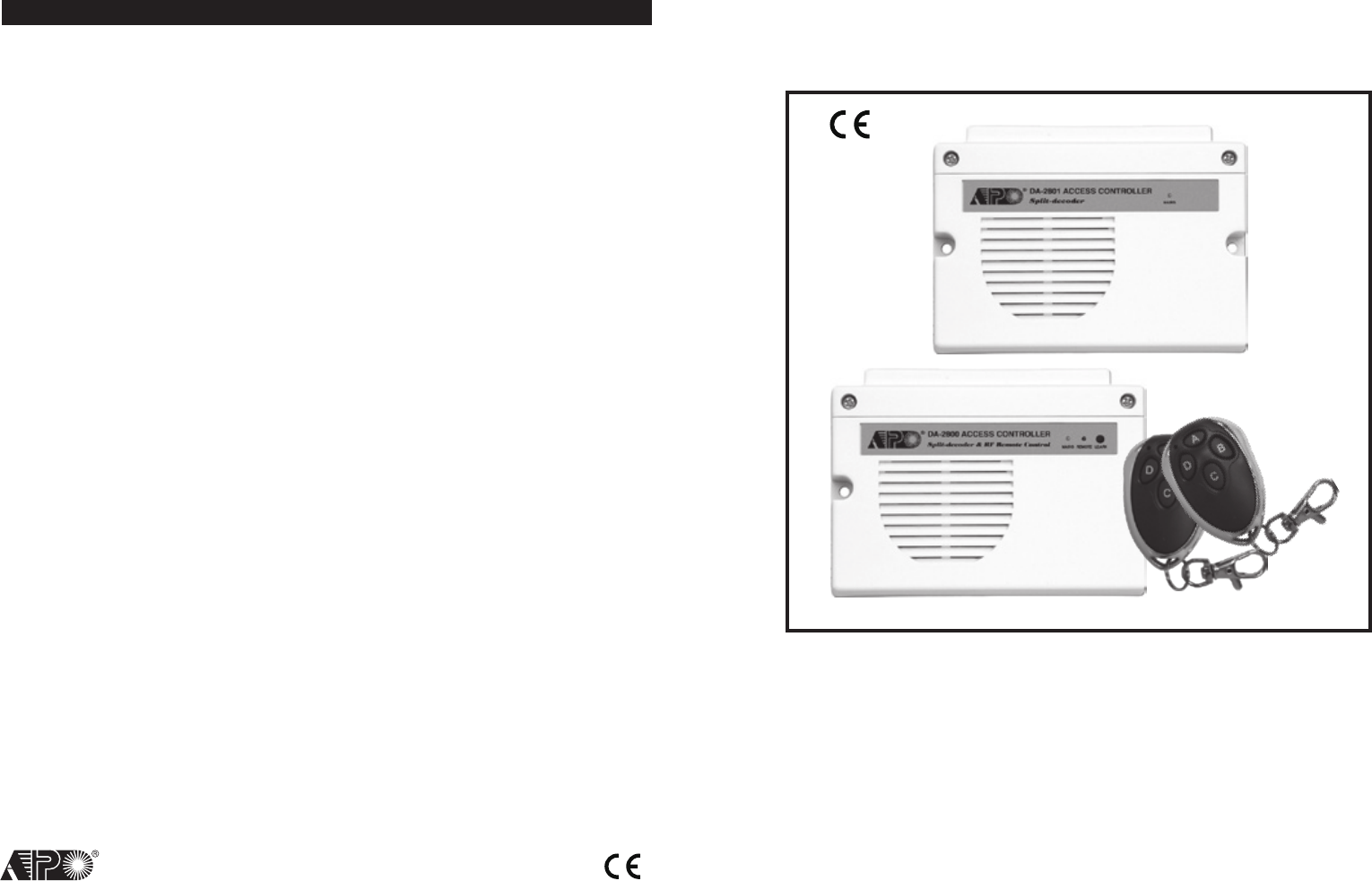
DA-2800 & DA-2801
Installation & Operation Manual
FOR ELECTRIC LOCK, INTER-LOCK
AND SECURITY SYSTEM INSTALLATIONS
VERSION: 10/2010
AEI
PROTECT-ON
SYSTEMS
LIMITED
www.apo-hk.com
RoHS
Compliance
FCC STATEMENT
1. This device complies with Part 15 of the FCC Rules.
Operation is subject to the following two conditions:
(1)This device may not cause harmful interference, and
(2)This device must accept any interference received, including interference
that may cause undesired operation.
2. Changes or modifications not expressly approved by the party responsible for
compliance could void the user's authority to operate the equipment.

TABLE OF CONTENTS
INTRODUCTION
FEATURES
SPECIFICATIONS
PACKAGE CONTENTS
THE SPLIT-DECODED CONTROLLER UNIT (Figure 1)
THE MAIN CIRCUIT BOARD OF THE CONTROLLER --- (Figure 2)
INSTALLATION
Precautions
Split-Decoded Mode -- (For DA-2800 & DA-2801)
The Necessary Connections For Split-Decoded
The Function Mode Jumper Setting For Split-Decoded -- (DA-2800 Only)
The Link-Up Jumper & Link-Up Code Acquisition
The Function Mode Jumper -- (Available On DA-2800 Only)
CONNECTION TERMINALS
The Audible & Visible Signals
The Alarm Outputs & Warnings
RF Remote Controller -- (DA-2800 Only)
Stand Alone Mode -- (DA-2800 Only)
APPLICATION EXAMPLES
Basic Wirings of A Split-Decoded Door Lock
Basic Wirings of An Inter-Lock System Using Two Split-Decoded Keypads
APPLICATION HINTS FOR THE AUXILIARY TERMINALS
PROGRAMMING FOR FULL FEATURES --- (Supplementary Information)
Set System in Programming Mode with The Master Code
Direct Access to Programming Mode with The “DAP” Code – 8 0 8 0
Refresh The System with The “Refreshing Code” --- 9 9 9 9
The Default Values of The Keypad
FEATURE PROGRAMMING -- KEY IN AND STORE THE DESIRED VALUES
Programming Criteria for Codes
Record A Master Code
Record A Super User PIN
Operation And Functions of The Super User PIN
Record The Common User PINs for Output 1, 2 & 3
Record-Delete PINs or Cards for Output 1, 2, & 3
Examples – Programming And Operation
Visitor Codes (For Output 1 Only)
Duress Codes (For Outputs 1, 2 & 3)
The Operation And Function of The Duress Code
Configuration of The Output Modes for Output 1, 2 And 3
Personal Safety And System Lock-Out
2
..........................................................................................4
..............................................................................................4
..........................................................................................5
.....................................................................................5
............................................................6
.................................................6
............................................................................................7
............................................................................................7
.............................................................7
...............................................................8
.........................................8
.............................................................8
....................................................9
.................................................................................1 0
............................................................................1 4
..........................................................................1 4
...................................................................1 5
.....................................................................1 5
.................................................................................1 6
................................................................1 6
.......................................1 7
.......................................................1 8
.........................................2 1
....................................................2 1
...........................................2 2
..................................................2 3
.......................................................................2 3
........................................2 4
..........................................................................2 4
..................................................................................2 5
...............................................................................2 5
.............................................................2 6
.........................................................2 6
............................................................2 7
...............................................................2 8
........................................................................3 0
....................................................................3 1
.........................................................3 2
....................................................3 3
...................................................................3 3
41
8 0 Door Forced Open Warning
& Time
FUNCTION MODE / TIME:
0---OFF
1-999 Seconds 80 FUNCTION / TIME #
Mode = 0,
Door Forced
Open
Warning OFF
8 1 Propped-up Warning & Time 81 FUNCTION / TIME # Mode = 0,
Propped-up
Warning OFF
9 0 Egress Delay Warning &
Alarm
CODE 1
-
FUNCTION MODE:
1---Momentary, No warning
2---Momentary, with warning
3---Momentary, with warning +
Alarm
4---Hold Contact, No warning
5---Hold Contact, with warning
6---Hold Contact, with warning
+ Alarm
CODE 2
-
DELAY TIME:
0---No Delay
1-99 Seconds
90 CODE 1 CODE 2 #
Mode = 1
Momentary,
No warning
TIME = 0
No Delay
9 1 Door Opening Alarm &
TIMER
ALARM TIME:
0---No Alarm
1-999 Seconds
91 ALARM TIME # Time = 0,
No Alarm
9 4 Operation Mode & Wiegand
Output
MODES OF WIEGAND OUTPUT
0---Stand Alone Keypad
-
Valid
Codes & Cards Only
1---Reader
-
All Codes & Cards
2---Master Keypad
-
Valid Codes
& Cards only
3---Slave Keypad
-
Valid Codes
& Cards only
94 WIEGAND O/P MODE # Mode = 0
Keypad Mode
SYSTEM CODES FUNCTION CODE ENTRY RESULTS
0 0 0 0
Factory Set Master Code
for User to set system in
programming Mode at the
first time.
THIS IS NOT A PERMANENT
SYSTEM CODE & IT IS
CHANGED IF A NEW MASTER
CODE IS PROGRAMMED.
0000 * *
OR
NEW MASTER CODE * *
System in Programming Mode
9 9 9 9
REFRESH CODE -- Refresh
the system and set all its
function back to default
values.
9999 # All programmed data are cleared and
back to the default values except the
Master Code
8 0 8 0
DAP CODE-- Direct access
to programming mode. Valid
only in the power-up delay
period
8080 # System in Programming Mode
0 9 9 9
USER PINs / Codes / Cards
whole group clearance Code
-
Key in the Code to clear all
the users in the Location
LOCATIONS:
10--- User Group 1
20--- User Group 2
30--- User Group 3
40--- Vistor Group
41--- Duress Group 1
42--- Duress Group 2
43--- Duress Group 3
LOCATION NO. 0999 # Whole group of users in the selected
location are cleared
* * Exit Programming Code ** The system back to normal opration
after programming
3
User PIN Entry Mode
Pacifier Tones On-Off Selection
Output Operation Announcer
Status LED Flashing On-Off during Standby
Door Forced Open Warning & Timing
Door Propped-Up Warning & The Delay Time
Intelligent Egress Button – An Unique Feature of A Contemporary Keypad
Where And Why “Going Out” Needs Attention
Egress Delay , Warning And Alarm
Configurations of The Egress Warning And Alarm
Door Opening Alarm & Timer
Close The Programming Mode
The Operation Modes and The Wiegand Output
Wiegand Output at Keypad Operation Mode
PROGRAMMING SUMMARY CHART --- (Supplementary Information)
...................................................................................3 4
..........................................................................3 4
.............................................................................3 4
.................................................................3 5
.....................................................................35
..............................................................3 5
.......................................3 6
.............................................................3 6
........................................................................3 7
.........................................................3 7
.............................................................................3 8
...........................................................................3 8
..............................................................3 9
..............................................................3 9
............................................4 0
40
THE PROGRAMMING SUMMARY CHART --- (Supplementary Information)
LOCATION FUNCTION ENTRY LIMITS & CODE
OPTIONS CODE ENTRY FACTORY
DEFAULT
0 1 Master Code 4-8 Digits 01 MASTER CODE # NIL
0 2 Super User PIN 4-8 Digits 02 SUPER USER PIN # NIL
0 3 Common User PIN for O/P 1
4-8 Digits
03 COMMON USER PIN 1 # NIL
0 4 Common User PIN for O/P 2 04 COMMON USER PIN 2 # NIL
0 5 Common User PIN for O/P 3 05 COMMON USER PIN 3 # NIL
1 0 User PINs / Cards for O/P 1
CODE 1
-
MEDIA:
1---EM Card
2---Private User PIN
3---EM Card+Sec User PIN
4---EM Card+Com User PIN
5---Deletion of User PIN
CODE 2
-
USER ID:
000-999---Group 1(10)
001-100---Group 2(20)
001-100---Group 3(30)
CODE 3
-
USER PINs / Cards:
4-8 Digits / Cards
10 CODE1 CODE2 CODE3 #NIL
2 0 User PINs / Cards for O/P 2 20 CODE1 CODE2 CODE3 #NIL
3 0 User PINs / Cards for O/P 3 30 CODE1 CODE2 CODE3 #NIL
4 0 Visitor Codes
CODE 1
-
VISITOR ID: 01-50
CODE 2
-
VALID PERIOD:
00---One Time
01-99 Hours
CODE 3
-
VISITOR CODE:
4-8 Digits
40 CODE1 CODE2 CODE3 #NIL
4 1 Duress Code for O/P 1 CODE ID
-
O/P 1: 01-50
CODE ID
-
O/P 2: 01-10
CODE ID
-
O/P 3: 01-10
DURESS CODE: 4-8 Digits
41
CODE ID
DURESS CODE
# NIL
4 2 Duress Code for O/P 2 42
CODE ID
DURESS CODE
# NIL
4 3 Duress Code for O/P 3 43
CODE ID
DURESS CODE
# NIL
5 1 O/P Mode for O/P 1 OUTPUT MODE & TIME:
0--- Start / Stop
1---99999 Seconds,
Momentary
51 O/P MODE & TIME # 5 Seconds
5 2 O/P Mode for O/P 2 52 O/P MODE & TIME # 5 Seconds
5 3 O/P Mode for O/P 3 53 O/P MODE & TIME # 5 Seconds
6 0 Personal Safety & Lock-out
LOCK-OUT CODE:
1---10 Trial, Lock-out 60 Sec.
2---10 Trial, Activates Duress
5-10---5-10 Trial, Lock-Out 15
Minutes
00---No Lock-out
60 LOCK-OUT CODE #
Code = 1,
10 Trials,
Lock-out 60
Seconds
7 0 PIN Entry Mode
ENTRY MODE:
1---Auto Mode
2---Manual Mode
70 ENTRY MODE # Mode = 2,
Manual Mode
7 1 Pacifier Tone ON-OFF
FUNCTION MODE:
0---OFF
1---ON
71 FUNCTION MODE # Mode = 1,
Pacifier Tone
ON
7 2 Output Announcer 72 FUNCTION MODE # Mode = 1
Announcer ON
7 3 Standby LED Flashing 73 FUNCTION MODE # Mode = 1,
Flashing On

INTRODUCTION
The DA-2800 or DA-2801 is a self-contained access controller. It has been designed mainly as the decoder unit
working together with the keypads in the DK-2800 series to make up a split-decoded keypad system.
In split-decoded operation the system provides full Tri-Tech features of accepting EM Card, PIN/Code and RF Remote
Control. This unique design philosophy makes the system to provide high level of security in preventing sabotage far
ahead of the traditional stand alone keypad systems.
The DA-2800 also has been designed to work stand alone without keypad. The three relay outputs can be controlled
by the RF remote control key directly. The Output 1 operates in Start/Stop mode or in Momentary mode with the built-
in adjustable timer for door strike. The Output 2 and 3 operate in Start/Stop mode and manually controlled Momentary
mode respectively.
DA-2801 is the simplified version without the RF remote control function. It is solely a full feature decoder of the DK-
2800 series keypads in Split-decoded operation.
The DA-2800 or DA-2801 has three output relays and a built-in door chime. It is an ideal device for Door Strike, Alarm
Arm-disarm control and actuation of Automatic Operator, such as garage door opener.
The keypad system with the DA-2800 or DA-2801 decoder in Split-decoded operation offers full features performance
even the keypad is just a simplified version. Maximum three keypads can be connected in parallel to the decoder unit
with one of them setting in master mode and the other two setting in slave mode. Each keypad can be programmed
with its own PINs and Cards. The slave keypads take the features and the functions programmed in the master keypad
to operate the system. The decoder interprets the data and operates the desired functions faithfully.
FEATURES
DA-2800 – Full Feature Decoder + RF Remote Control
DA-2801 – Full Feature Decoder
I) DA-2800 & DA-2801
• A Decoder for The DK-2800 Series Keypads in Split-decoded Operation
• Decodes The Data of EM Cards, PINs / Codes & Functions Faithfully from Keypads
• Provides Full Features in Split-Decoded Mode for Any Keypad in The DK-2800 Series
• Simple Three Wires Connection to Keypads For Data Communication, (+), (
-
) & Data I/O
• Easily to Set Up Link Up Code with The Keypads And The Decoder
• Three Independently Controlled Output Relays
• Built-in Door Chime
• Built-in Alarm for Tamper, Door Forced Open and Door Opening in Split-Decoder Mode
• Built-in Current Limited (750mA) Power Source for The Keypads to Prevent Sabotage of Short Circuit from Outside
II) DA-2800 Only
• Provides The Tri-Tech Features of RF Remote Control, Card and PIN/Code Reading in One System
• 24 bits Self-learning Codes (over 1 million codes) for The RF Remote Control Keys
• Accepts 40 RF Remote Control Keys Maximum
• 4 RF Remote Control Channels for Stand Alone or Split-decoded Operation
• Remote Control Key Controls Output 1, 2, 3 & Door Chime
4
CLOSE THE PROGRAMMING MODE ( * * )
Always close programming mode with * * to set system back to normal Operation after programming.
The button is equivalent to the * button in the keypad with bell button.
VALIDATION
** --------------- System is back to normal operation mode
THE OPERATION MODES AND THE WIEGAND OUTPUT (Location 94)
Four operation modes are available for the selection. The codes are 0, 1, 2 and 3.
WIEGAND OUTPUT AT KEYPAD OPERATION MODE
0 --- Stand Alone Keypad Mode -- (Default)
The system provides full functions to operate its outputs and at the same time provides Wiegand Data Output for all the
VALID Cards and User PINs including the Duress Codes and Visitor Codes. No Wiegand Data Output for the invalid PINs
and Cards.
1 --- Card & Code Reader Mode
In the Card & Code Reader Mode, the keypad provides Wiegand Data Output for all the Card readings and PINs/Code
entries but does not operate its outputs. It is solely a card and code reader.
NOTE:
It is suggested to clean all the codes, PINs and cards that were previously stored in the system before setting the
system for reader mode.
2 --- Master Keypad of Split-Decoded Mode (The Only Mode will Send Out the Link-up Code)
The keypad unit provides the Wiegand Data Output for the valid user PINs, Codes and Cards exactly like in the Stand
Alone Mode. The Master keypad will transfer all the programmed feature data (except the user PINs, Codes and Cards
data) to the Access Controller (decoder) right after it exits the programming mode. A Split-decoded keypad system
needs at least one Master keypad and one Access Controller to work.
3 --- Slave Keypad of Split-Decoded Mode
The Keypad unit provides the Wiegand Data Output for the valid user PINs, Codes and Cards exactly like in Stand Alone
Mode. No feature data is transferred to the Access Controller (decoder) from the Slave keypad. It takes the same feature
data from the Master keypad to operate. The Slave keypad(s) is for a Split-Decoded system that needs more than one
keypads for operation convenience.
NOTE:
a) Do not set more than one keypads in Master mode in a Split-Decoded system. Otherwise, the data will be confused.
b) Each keypad in Split-Decoded mode can be programmed independently with its own user PINs, Codes and Cards.
The PINs, Codes and Cards can be repeatedly used in other keypads in the same system.
OPERATION MODELOCATION VALIDATION
#0 , 1 , 2 or 394
39
.
INDIVIDUAL
INDIVIDUAL

SPECIFICATIONS
Operating Voltage:
12V-24V DC, Auto Adjusting
Operating Current:
65mA (quiescent) to 100mA (three relays active)
Operating Temperature:
-20 C to +70 C
Environmental Humidity:
5-95% relative humidity non-condensing
The Adjustable Timer for Output 1:
1-30 Seconds
Power Up Delay:
5 Seconds
Tamper Alarm:
3 Minutes
Input Sensing Terminals:
a) Door position, b) Egress, c) O/P 1 Inhibit, d) Door Bell, e) Tamper
Output Control Terminals:
a) Duress, b) Alarm, c) Key Active, d) Inter-lock;
Transistor Open Collector, 24VDC/100mA sink Max
Output Contact Ratings:
Output Relay 1 – N.C. & N.O. dry contacts, 5A/24VDC Max.
Output Relay 2 – N.C. & N.O. dry contacts, 1A/24VDC Max.
Output Relay 3 – N.C. & N.O. dry contacts, 1A/24VDC Max.
Dimensions:
32.5(H) X 120(W) X 87(D)mm Plastic Box
Weight:
250g net
RF Remote Controller (DA-2800 Only) :
Number of Self-leaning Codes : Over 1 Million
Number of RF Control Keys : 40 Maximum
4 Control Channels : Output 1, 2, 3 & Door Chime
Operation Frequency : 433.92MHz
Control Distance : 60 Meters Approx. in Open Space
Receiver Type : Super-heterodyne
Operation Voltage : 12V Alkaline Battery, Type 27A (Battery Not Included)
Weight : 32g
Specifications are subject to change for modification without notice
PACKAGE CONTENTS
• One Access Controller
• One Pack of Mounting Screws
• Two RF Remote Control Keyfobs (DA-2800 Only), Battery Not Included
• One Owner’s Manual
5
EXAMPLES:
Example 1: Set Egress Button in Momentary contact 5 seconds with delay & warning beep
90 2 5 #
(a) (b) (c) (d)
(a) Egress function programming, (b) Momentary contact with warning, (c) Delay time of 5 seconds to release door,
(d) Entry confirmation
Example 2: Set Egress Button in Holding contact of 10 seconds with warning beep
90 5 10 #
(a) (b) (c) (d)
(a) Egress function programming, (b) Holding contact mode with warning, (c) Holding time of 10 seconds to release
door, (d) Entry confirmation
Example 3: Set Egress Button in Momentary contact without delay (This is the default setting)
90 1 0 #
(a) (b) (c) (d)
(a) Egress function programming, (b) Momentary contact without delay, (c) Release door instantly, (d) Entry
confirmation
DOOR OPENING ALARM & TIMER (Location 91)
ALARM & TIMING OF DOOR OPENING
0 --- No Alarm – (Default)
The Alarm Output is disabled
1 – 999 --- Alarm Timer
The Door Open Alarm operates the Alarm Output (Terminal 13) only. It is mainly prepared to trigger an optional alarm
system. Put any Timing Figure of 1 to 999 into the box to enable the function of the Door Opening Alarm. The figure
is the time in second of the alarm duration, which starts to count after the door is opened and it resets automatically
when the time reaches.
The alarm can be stopped with the User Codes/Cards or the Super User PIN for Output 1 at any time before the end
of the alarm time.
NOTE: The Door Opening Alarm is designed to protect the emergency exit door from use by the un-authorized person.
The alarm occurs when the door is opened or forced to open. However, Alarm will not happen if the door is opened with
a valid User Code or Card.
The Manner of The Door Opening Alarm:
a) The door is forced to open without using PIN/Card – Alarm
b) The door is opened with Egress Button – Alarm
c) The door is opened with PIN/Card – No Alarm
To prevent confusion of the alarm outputs. It is suggested to disable the "Door Forced Open Warning" at Location 80
while "Door Opening Alarm" function is enabled. If both functions at Location 80 and Location 91 are enabled and are
set with different timings, the system will combine them and will take the longer one for alarm time.
ALARM TIME VALIDATION
LOCATION
0 or 1
-
99991 #
38
MASTER
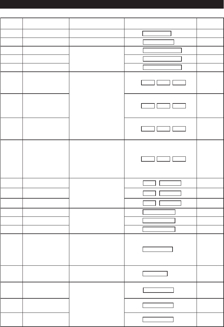
THE SPLIT-DECODED CONTROLLER UNIT (Figure 1)
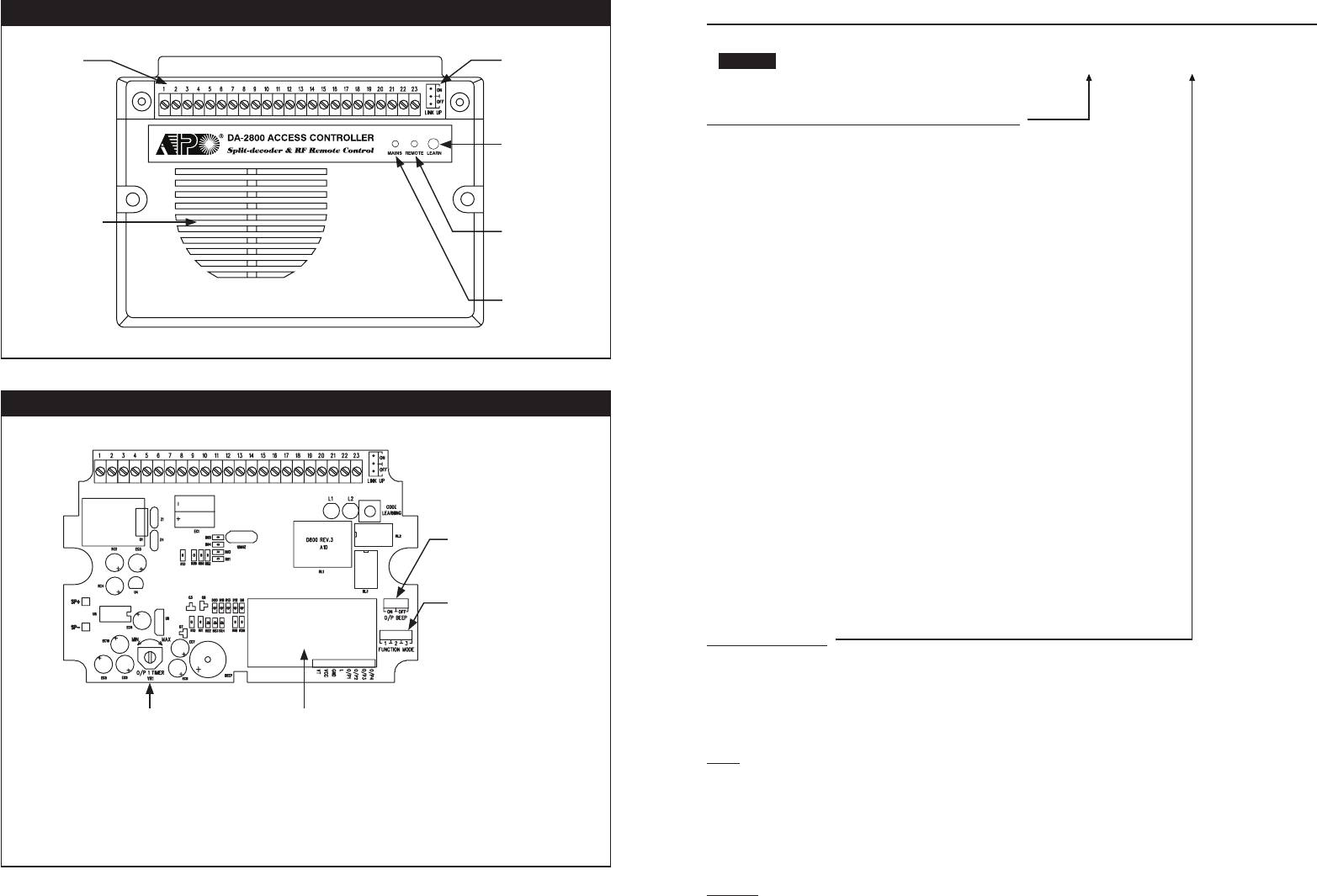
THE MAIN CIRCUIT BOARD OF THE CONTROLLER --- (Figure 2)
NOTE: Factory suggest that the work of timer adjustment and change of jumper settings on the main circuit board are
to be done by the Installer only.
No adjustment/setting change is required for Split-decoded operation with the ex-factory settings.
6
LINK-UP JUMPER
OFF-->ON-->OFF
CODE LEARNING
BUTTON
(DA-2800 ONLY)
REMOTE CONTROL
SIGNAL & STATUS
(DA-2800 ONLY)
INTERNAL SIREN
& DOOR CHIME
CONNECTION
TERMINALS
MAINS
OUTPUT BEEP JUMPER
ON OR OFF
FUNCTION MODE JUMPER
1. SPLIT-DECODED
2. STAND ALONE MODE 1
3. STAND ALONE MODE 2
ADJUSTABLE TIMER
FOR OUTPUT 1
TURN CLOCKWISE FOR
MAXIMUM TIME
RECEIVER FOR
REMOTE CONTROL
(DA-2800 ONLY)
EGRESS DELAY , WARNING AND ALARM (Location 90)
CONFIGURATIONS OF THE EGRESS WARNING AND ALARM
Key in the number to enable 1 of the 6 configurations described below:
1 --- Momentary Contact Mode without Warning -- (Default)
• Press the Button once. No warning or alarm is given during Egress Delay.
• Good for silent area. The people have to wait for the door open until the delay time
reaches.
2 --- Momentary Contact Mode with Warning Beep
• Press the Button once. The system gives Warning Beeps during the Egress Delay.
• Good for the place required attention. The keypad beeps during the people are waiting for
the door open.
3 --- Momentary Contact Mode with Warning Beep & Alarm
• Press the Button once. The system gives Warning Beeps and also activates its Alarm O/P
during the Egress Delay
• Good for door for the authorized people only. The keypad beeps and report alarm to a
security system during the people are waiting for the door open.
• This is usually an “Emergency Exit”. The door can be opened with the Keypad without
triggering of the Buzzer and Alarm Output.
4 --- Holding Contact Mode without Warning
• Press and hold the Button. No warning or alarm is given during the Egress Delay.
• Good for the silent area. The people require to press & hold the button until the delay time
reaches for the door open.
5 --- Holding Contact Mode with Warning Beep
• Press and hold the Button. The system gives Warning Beeps during Egress Delay.
• Good for the place required attention. The keypad beeps while the button is kept pressed
during the people are waiting for the door open.
6 --- Holding Contact Mode with Warning Beep & Alarm
• Press and hold the Button. The system gives Warning Beeps and also activates its Alarm
O/P during Egress Delay.
• This is usually an “Emergency Exit”. The door can be opened with the Keypad without
triggering of the Warning and Alarm.
EGRESS DELAY TIMER
0 --- No Delay – (Default)
Output 1 activates instantly (the door is released instantly) when the Egress Button is pressed.
1 – 99 --- Egress Delay Timing
Put any number of 1 to 99 into the box to enable the Egress Delay. The number is the time in second, which starts to
count when the Egress Button is pressed. Output 1 activates (the door is released) when the delay time reaches.
NOTE:
1) Momentary Contact -- The Egress Delay starts to count when the egress button is momentarily pressed. Output 1
activates automatically (door is released) when the delay time reaches.
2) Holding Contact -- The user MUST hold the egress button in contact for the whole period of the Egress Delay time
until Output 1 activates. If the egress button is released before the end of the Egress Delay, the timer will stop to count
and reset.
3) The Egress Delay does not affect the operation of the User PINs/Cards for Output 1. The User PINs/Cards always
give INSTANT action.
Examples: (please see the following page)
FUNCTION MODES VALIDATIONDELAY TIMELOCATION
1
-
6 0 or 1
-
99 #90
37
MASTER
INSTALLATION
PRECAUTIONS
1) Installation Location:
The built-in receiver of the Access Controller is working at the UHF frequency band of 433.92MHz. To get the best
receiving result of the signals from the remote keys a correct installation location is necessary.
i) Install it on a location inside the house facing to the open space and there has no strong electro-magnetic wave
signals near it.
ii) Do not install it in a concrete room or under a concrete stair, which shortens the control distance.
2) Prevent Accidental Short Circuit:
In the previous experience, most of the damages caused in the installation are accidental touching of the components
on circuit board with the wires carrying power. Please be patient in the installation. Study the manual to become
familiar with the specifications of the system beforehand is also important.
i) Do not apply power to the system while it is in installation.
ii) Check carefully all the wirings are correct before applying power to the system for testing.
SPLIT-DECODED MODE -- (for DA-2800 & DA-2801)
Split-decoded Mode needs at least one keypad to work with the decoder. The decoder decodes all the commands
from the keypad to operate its outputs. It is an unique solution to immediately up-grade a general purpose keypad to a
high security access control system. All the keypads in the DK-2800 series with Data I/O Port are compatible with the
decoder. A Split-decoded system divides itself into the outside keypad unit and the inside decoder unit. Any sabotage to
the outside unit does not affect the security of the inside unit.
7
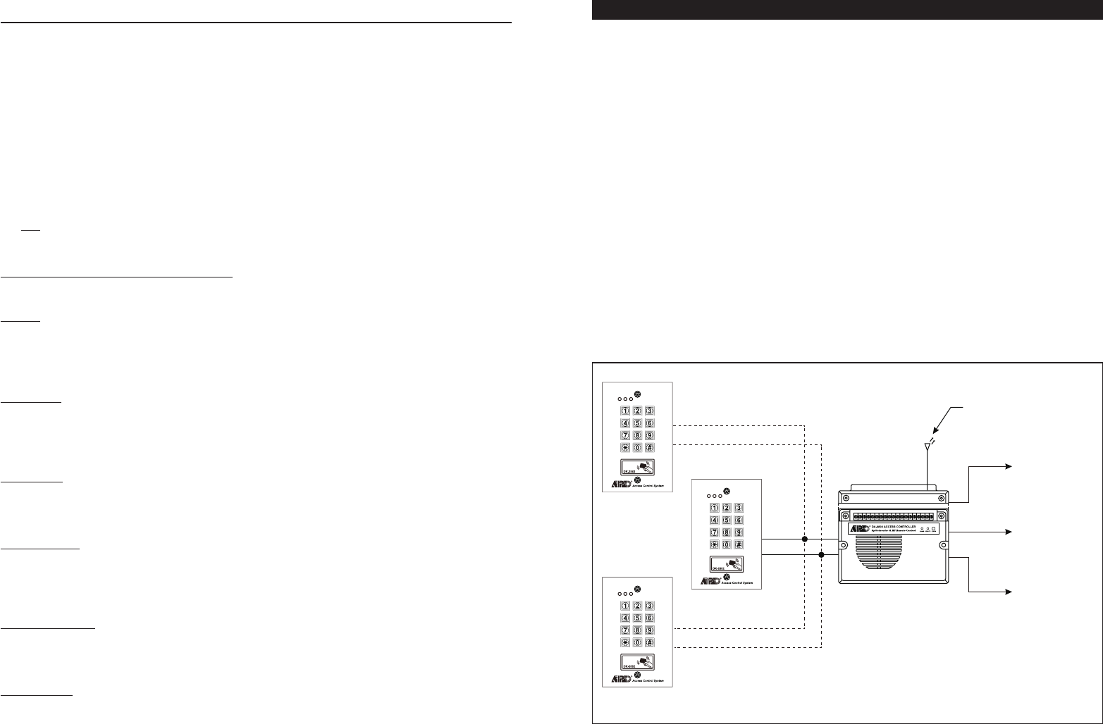
RF WIRELESS
REMOTE CONTROL (DA-2800 ONLY)
DOOR LOCK
(OUTPUT 1)
SECURITY
SYSTEM (OUTPUT 2)
AUTOMATIC
OPERATOR (OUTPUT 3)
COMMON
GROUND
COMMON
GROUND
DA-2800 OR DA-2801
SLAVE 1
SLAVE 2
MASTER
DATA I/O
COMMON
GROUND
DATA I/O
DATA I/O
MAXIMUM 3 KEYPADS CAN BE CONNECTED IN PARALLEL
INTELLIGENT EGRESS BUTTON – AN UNIQUE FEATURE OF A CONTEMPORARY KEYPAD
Most of the keypads for access control are just for controlling of “Going In” from outside. It is not enough for today’s
access control systems. In fact, controlling of “Going Out” is also very important in many public passage areas. They
are not allowed to use locks or digital keypads for stopping of “Going Out” due to safety reasons. Such as hospitals,
kindergartens, elderly homes, convenient stores, emergency exits etc.. The wardens, teachers, shopkeepers and the
guards are always required to keep an eye on people to prevent unattended leaving, shoplifting, and illegal use of the
emergency exits.
The Intelligent Egress Button can be programmed to do something to get the attention of the person on duty before the
door is opened. The button offers programmable egress delay, delay with warning, holding button required for the delay,
momentary button contact with warning for the delay and even gives alarm when a controlled door is opened.
Locations 90 and 91 below are the places for setting the desired functions for the Egress Button.
The functions programmed to the Egress Button do not affect the normal operation of the system with its keypad. For
the safety consideration, the operation of the keypad with PIN, Code or Card is always in the first priority to give instant
action to the output relay 1 for door strike.
It is NOT required to program the Egress Button with the special function in normal use. Just leave it on its default
values.
WHERE AND WHY “GOING OUT” NEEDS ATTENTION
Examples for some areas may need an Intelligent Egress Button:
Hospital:
Some of the patients are not allowed to leave the ward without doctor’s permission. An egress button with exit delay
and warning beeps will help the nurse or warden to get the attention to the door when the egress button is pressed.
Further setting of the egress button with holding contact for the delay even gives higher level of security to a controlled
door.
Kindergarten:
Young children are always active. Some of them may be willing to go out to explore their ways of playing. For safety
reason, teachers have to watch all of them in the attended area. Leaving school alone without the companion of parents
or teacher is dangerous to the young children. An egress button with delay and warning beeps will be helpful to prevent
the children trying to go out without getting the attention of the teacher.
Elderly Home:
Elderly needs constant attention and care. Some old people have poor memory. They may forget the way to come
back if they leave home alone. An egress button with delay and warning beep will easily get the attention of the warden
before the door is open.
Convenient Store:
Most of the convenient stores have just only one or two shopkeepers on duty. They are usually the cashier. Shoplifting
may easily happen while the shopkeeper is busily serving customers at the cashier desk. A holding contact egress
button with delay and warning beeps may help to stop most of the shoplifting. As the thief knows that he is gotten
attention by the shopkeeper before the door is open.
High Traffic Passage:
A short buffer time may be necessary for opening a door outward after pressing the egress button for those exits open
to a high traffic passage. An egress button with short delay and warning beeps helps the user to pay attention to the
people passing by to prevent hitting them when the door is pushed outward.
Emergency Exit:
Emergency Exit is not open to the public for daily use. It is for emergency case only. It is usually closed and watched
by the security guards. The egress button of this keypad can be programmed to offer exit delay with warning beeps and
even gives alarm output to trigger an alarm system when the door is forced to open or the door is open after the exit
delay expired. It is an useful tool to get the attention of the person on duty.
36

THE NECESSARY CONNECTIONS FOR SPLIT-DECODED
1) Connect the Data I/O ports of the Decoder (Terminal 4) and the Keypad with wire to link-up the communication of
the two units.
2) Connect the Keypad PWR terminal of the Decoder (Terminal 3) to the keypad power input terminal, which supplies
power to the keypad unit with current limit protection.
3) Connect the Common (
-
) Ground (Terminal 2 or 11) to the (
-
) ground of the keypad unit to make up the return path
for the data and the power source.
4) Make all other installation connections to the decoder unit, but not to the keypad unit in Split-Decoded Mode. The
system provides full feature from the decoder unit according to the functions programmed in the keypad.
THE FUNCTION MODE JUMPER SETTING FOR SPLIT-DECODED -- (DA-2800 ONLY)
NOTE: No Function Jumper setting is required for the DA-2801. It is fixed in Split-Decoder mode.
1) Put the “Function Mode Jumper” to position “1” for Split-Decoder. (It is an Ex-factory Setting)
a) The Function Jumper of the DA-2800 has been put on Position 1 at the factory. Setting of the jumper is usually not
necessary unless it has been changed. Always put jumper on position “1” for Split-decoded mode.
b) The Function Jumper is located on the Main Circuit Board inside the box. Change the setting for Stand Alone mode is
required. See Figure 2.
2) Set the “Link-up Jumper” from OFF to ON position to enable the link-up of acquiring the link-up code from
the keypad (same as the Master Code of the keypad).
a) The Jumper is located on the main circuit board inside the terminal compartment. See Figure1.
b) The Decoder executes link-up Only Once. The Link-up execution is done when the keypad exits from Programming
Mode after pressing **. Put the jumper back to OFF position after link up.
c) After the decoder knows the link-up code (Master Code) of the keypad it is not necessary to repeat the link-up
procedure in feature change programming except change of the Master Code.
Remark:
a) All the keypads going to link up with the decoder MUST be with the same Master Code which is the authorization
code to enable the data communication between the keypads and the decoder.
b) It is not necessary to repeat the link-up procedures for the slave keypads with the same Master Code. Just simply
connect them in parallel with the master keypad.
c) The decoder will refuse other keypads that are not in the same Master Code to link up with it.
d) The failed keypads in the link-up will generate warning beeps.
THE LINK-UP JUMPER & LINK-UP CODE ACQUISITION
To acquire the link-up code (same as the Master Code) from the Master keypad for Split-Decoded operation is
necessary. At any time, when you operate a new Master keypad at the first time it is necessary to let the decoder unit
to know the Master Code of the keypad. Otherwise, the decoder can not recognize the data from it. If more than one
keypads are going to link up with the decoder, all the keypads are required to have the same Master Code and repeat
link-up is not necessary.
The decoder executes Link-up Acquisition Only Once at the moment after setting of the Master Keypad to exit
Programming Mode with **.
8
STATUS LED FLASHING ON-OFF DURING STANDBY (Location 73)
STANDBY FLASHING ON-OFF
Some people find the flashing light of the status LED (the amber LED) is annoying during the keypad is on standby,
especially at the night time. The standby flashing can be ON-OFF with the setting here.
1 --- Standby Flashing ON -- (Default)
The Status LED gives Standby Flashing all the time during the keypad is on standby. It also gives all the light
indications showing the operation status of the system.
0 --- Standby Flashing OFF
The Standby Flashing is disabled but it does not affect the system status indications. All the light indications from it
are unchanged.
DOOR FORCED OPEN WARNING & TIMING (Location 80)
DOOR FORCED OPEN WARNING ON-OFF & TIMING
The Door Forced Open Warning function requires a Door Position Sensing switch (usually a magnetic contact) to work
with. Once a Timing Figure is put into the Function Mode box, the warning mode is enabled.
0 --- Door Forced Open Warning OFF – (Default)
1
-
999 --- Door Forced Open Warning & Alarm ON & Timing
The Timing Figure for the Warning can be 1-999 seconds. The keypad generates the door forced open warning
beeps and activates the alarm output (Terminal 13) instantly if the door is forced to open without a valid User PIN/
Card or pressing of the Egress Button. The beeps and alarm will last as long as the time set on the timer and it can
be stopped at anytime with an User PIN/Card in Group 1 before the end of the time.
The Manner of The Door Forced Open Warning:
a) The door is forced to open (without using PIN/Card or Egress Button) – Warning & Alarm
b) The door is opened with PIN/Card – No Warning or Alarm
c) The door is opened with Egress Button – No Warning or Alarm
DOOR PROPPED-UP WARNING & THE DELAY TIME (Location 81)
DOOR PROPPED-UP WARNING ON-OFF & TIMING
If somebody opened the door and it is left open longer than the allowable delay time, the keypad will generate door
propped-up warning until the door is re-closed. There is warning beeps from the keypad only but does not activates
the alarm output.
0 --- Door Propped-up Warning OFF – (Default)
1
-
999 --- Door Propped-up Warning ON & The Delay Time
The Delay Time can be 1 to 999 seconds. It is the time allows the door to open without starting of the warning.
FUNCTION MODES
FUNCTION MODES
VALIDATION
VALIDATION
LOCATION
LOCATION
0 or 1
-
999
0 or 1
-
999
#
#
80
81
FUNCTION MODES VALIDATIONLOCATION
1 or 0 #73
35
MASTER
MASTER
INDIVIDUAL

9
Example – Change of the Link-up Code ( The Master Code of the Master Keypad)
a) Put the Link-up Jumper of the Decoder from OFF to ON
OFF ON
b) Set the Master Keypad to Programming Mode
EXISTING MASTER CODE * *
c) Set a New Master Code to the Master Keypad
NEW MASTER CODE #
d) Set the Master Keypad to exit from Programming Mode
* *
e) The Link-up in the system is done automatically
BEEP BEEP ----- From Keypad
f) Put the Jumper back to OFF
ON OFF
g) The system is in Split-decoded operation with the new Link-up Code
THE FUNCTION MODE JUMPER -- (AVAILABLE ON DA-2800 ONLY)
Three positions are available for the Function Mode Jumper. Position 1 is for Split-decoded Mode and the positions 2 &
3 are for Stand Alone Modes.
POSITION 1 – SPLIT-DECODER (MAINS LED LAMP FLASHING)
Position 1 is for Split-decoder mode. All the functions and the 3 output relay operation manners follow the programmed
settings in the Master keypad. All the functions of the decoder are programmable from the keypad unit. The DA-2800
system is controlled by the keypads and the remote control keys in the Split-decoded mode.
POSITION 2 – STAND ALONE MODE 1 – START / STOP FOR OUTPUT 1 (MAINS LED LAMP ON)
Position 2 is one of the settings for Stand Alone mode. All the three Output Relays are controlled by the RF Remote Key
with the following functions:
Output 1 – Start / Stop – Controlled by Channel 1 of the RF remote key. Press the Button A once to start and press the
button once again to stop.
Output 2 – Start / Stop – Controlled by Channel 2 of the RF remote key. Press the Button B once to start and press the
button once again to stop.
Output 3 – Manual Momentary – Controlled by Channel 3 of the RF remote key. The output relay operates (Starts) as
long as the Button C is pressed and it stops when the button is released.
POSITION 3 – STAND ALONE MODE 2 – ADJUSTABLE TIMER FOR OUTPUT 1 (MAINS LED LAMP ON)
Position 3 is one of the settings for Stand Alone mode. All the three Output Relays are controlled by the RF Remote Key
with the following functions:
Output 1 – Adjustable Timer – Controlled by Channel 1 of the RF remote key. Press the Button A once to start the timer
and it resets automatically after time out. It is adjustable 1-30 seconds. It is convenient for
setting the time for door strike. Turn the timer clockwise for maximum time. See Figure 2.
Output 2 – Start / Stop – Controlled by Channel 2 of the RF remote key. Press the Button B once to start and press the
button once again to stop.
Output 3 – Manual Momentary – Controlled by Channel 3 of the RF remote key. The output relay operates (Starts) as
long as the Button C on the remote key is pressed and it stops when the button is released.
ENTRY MODES VALIDATIONLOCATION
1 or 270 #
USER PIN ENTRY MODE – Auto or Manual (Location 70)
USER PIN ENTRY MODES
Two modes 1 and 2 are available for User PIN entry options. The EM Card is always in Auto Entry Mode and is not
affected by the selection here.
1 --- Auto Entry Mode
Auto Entry Mode requires no pressing of the # key following the User PIN for code checking.
In the Auto Entry Mode, the User PINs MUST be set in the same digit length of the Master Code (For example, if
the Master Code is 5 digits, then all User PINs must be in 5 digits as well. All other User PINs not in 5 digits become
invalid). When the number of digits reaches, the system will check the User PIN automatically. Good for high traffic
access control.
2 --- Manual Entry Mode – (Default)
Manual Entry Mode always requires the # key following of the User PIN for code checking. The User PINs can be 4-8
digits arbitrary and they are NOT required to be in the same digit length of the Master Code. Manual Entry increases
the level of security in the code trial by the unauthorized people.
PACIFIER TONES ON-OFF SELECTION (Location 71)
PACIFIER TONES ON-OFF MODES
The Pacifier Tone is the Beep Tones from the keypad, which include the tones of Successful Key entry (1 beep), the
Output Operation Announcer (2 beeps or 1 long beep) and the Unsuccessful User Code/Card entry (5 beeps).
NOTE :
The beeps for the Warning and the Power-up Delay do not belong to pacifier tones and can not be set to OFF.
1 --- Pacifier Tone ON – (Default)
All the Pacifier Tones available from the keypad are enabled. They are the response tones indicating the operation
status of the keypad after the Card/User Code is entered.
0 --- Pacifier Tone OFF
All the Pacifier Tones are OFF. Good for place needs for a silent environment.
OUTPUT OPERATION ANNOUNCER (Location 72)
OUTPUT OPERATION ANNOUNCER
The announcer gives notification beep to the users and the visitors on the operation status of the outputs. There are
two notification modes available for the selection.The notification is also OFF while the Pacifier Tone OFF mode in the
Location 71 is selected.
1 --- 1 Second Long Notification -- (Default)
1 second notification beep is given when the output relay is activated with a valid Card/Code or Egress Button. It is
prepared to notify the person outside the door when the lock is released and the door can be opened. It is good for
the door lock device gives no sound when it activates, such as a magnetic lock.
0 --- 2 Short Beeps Notification
2 short beeps notification is given when the output is activated with a valid Card/Code.
FUNCTION MODES VALIDATIONLOCATION
FUNCTION MODES VALIDATIONLOCATION
1 or 0
1 or 0
#
#
71
72
34
INDIVIDUAL
INDIVIDUAL
INDIVIDUAL
10
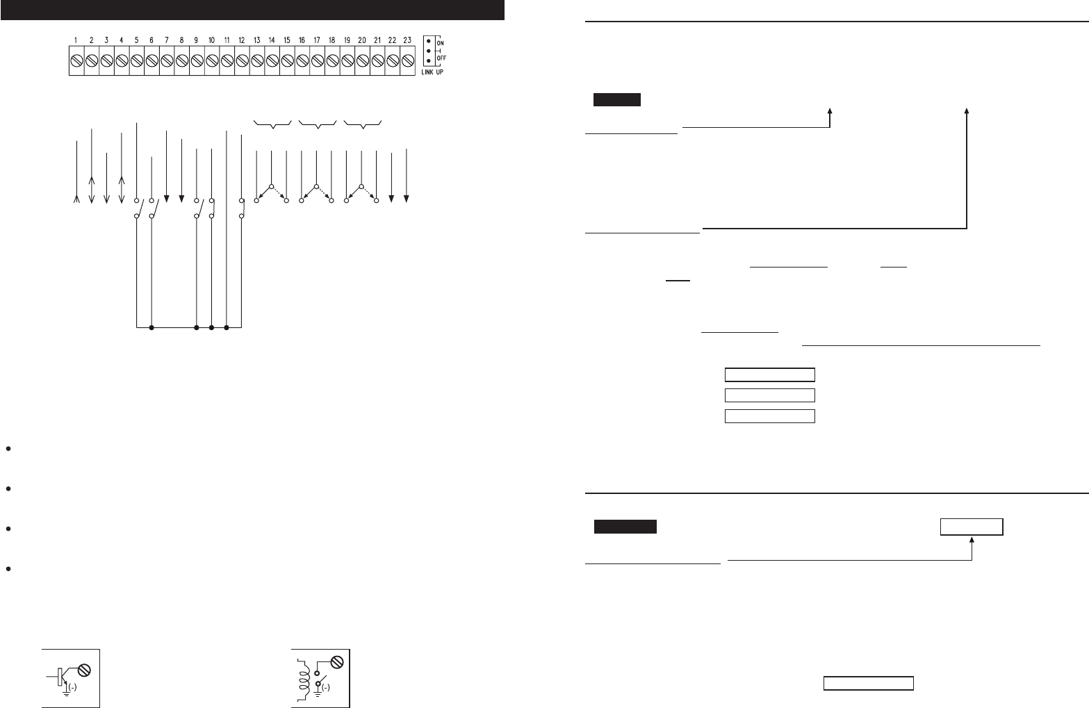
CONNECTION TERMINALS
NOTE:
DRY CONTACT
A dry contact means that no electricity is connected to it. It is prepared for free connections.
N.C.
Normally Closed, the contact is closed circuit at normal state. It is open circuit when active.
N.O.
Normally Open, the contact is open circuit at normal state. It is closed circuit when active.
TRANSISTOR OPEN COLLECTOR OUTPUT
An open collector output is equivalent to a Normally Open (N.O.) contact referring to ground similar to a relay
contact referring to ground. The transistor is normally OFF, and its output switches to ground (
-
) when active. The
open collector can only provide switching function for small power but it is usually good enough for controlling of
an alarm system. The maximum rating is 24V DC/100mA Sink
OPEN COLLECTOR
OUTPUT ----
Output switches to
ground when activated
N.O. CONTACT
OUTPUT ----
Output switches to
ground when activated
EQUIVALENT
-
ALARM O/P
-
KEY ACT O/P
-
N.O.
-
COM
-
N.C.
-
N.O.
-
COM
-
N.C.
-
N.O.
-
COM
-
N.C.
-
TAMPER
-
GND(
-
)
-
DOOR SENS
-
O/P 1 INHIB
-
INT. LOCK
-
DU OUT
-
DOOR BELL IN
-
EG IN
-
DATA I/O
-
KEYPAD PWR
-
GND(
-
)
-
12-24V DC
OPEN COLLECTOR OUTPUT
OPEN COLLECTOR OUTPUT
1A RELAY DRY CONTACTS
FOR AUXILIARY CONTROL
1A RELAY DRY CONTACTS
FOR AUXILIARY CONTROL
5A RELAY DRY CONTACTS
FOR DOOR STRIKE
OPEN COLLECTOR OUTPUT
OPEN COLLECTOR OUTPUT
INPUT/OUTPUT FOR SPLIT-DECODED SIGNALS
POWER OUTPUT FOR KEYPADS
COMMON GROUND
POWER INPUT FOR SYSTEM
N.C. SW
COMMON GROUND
N.C. SW
N.O. SW
N.O. SW
N.O. SW
OUTPUT 1O UTPUT 2O UTPUT 3
CONFIGURATION OF THE OUTPUT MODES OF OUTPUT 1, 2 AND 3 (Locations 51, 52 & 53)
The three relay outputs of this keypad are programmable for Start/Stop or Timing modes. Apart from the door access
control, alarm arm-disarm control, they are also universal timers for automatic operators in industry with their
99,999 seconds (over 24 hours) programmable timer.
OUTPUT LOCATIONS
51 -- Location for Output 1
52 -- Location for Output 2
53 -- Location for Output 3
OUTPUT MODE & TIMING
0 – Start /Stop Mode (Toggle)
The number 0 sets the output to the Start / Stop mode. The output Starts when an User PIN and/or Card is entered/
read; the output Stops when an User PIN and/or Card is entered/read again.
1
-
99999 Seconds Momentary --- (Default -- Momentary 5 Seconds)
The output can be set in Momentary Mode with the time of 1 second to 99,999 seconds. The output will reset
automatically when the time expires OR it can be RESET manually at anytime with the Super User Code that
operates the desired output before the end of the time.
Example : Reset Output 1 -- # 1 ------------- Output 1 resets
Reset Output 2 -- # 2 ------------- Output 2 resets
Reset Output 3 -- # 3 ------------- Output 3 resets
PERSONAL SAFETY AND SYSTEM LOCK-OUT (Location 60)
SAFETY & LOCK-OUT OPTIONS
The Options are represented by their Mode Numbers in programming. They are described below:
1 --- After 10 successive false Card/User Code trials, the keypad locks during 60 seconds. -- (Default)
2 --- After 10 successive false Card/User Code trials, activates the Duress output to switch to (
-
) ground.
The Duress Output can be released with any user PIN or Card in the User Group 1 or Super User PIN.
5
-
10 --- Selection of after 5 to 10 successive Card/User Code trials, the keypad locks during 15 minutes.
The keypad can be reset to release the lock-out with the “Super User Code” in the following way.
Example : Release the lock-out -- # 9
00 --- Disappearance of all the above lock-out securities.
SUPER USER CODE
SUPER USER CODE
SUPER USER CODE
1 to 2 Digits
LOCK-OUT MODES VALIDATIONLOCATION
60 #
SUPER USER CODE
OUTPUT MODE & TIME VALIDATIONLOCATIONS
51
-
53 0 or 1
-
99999 #
33
MASTER
INDIVIDUAL

1 - 2 : 12-24V DC I/P -- (Power Input Terminal)
Connect to a 12-24V DC power supply. The (
-
) supply and the (
-
) GND are the common grounding points of the
system. The system accepts full input voltage range.
3 : KEYPAD POWER O/P -- (Power Output for External Keypads – 500mA Max.)
This power source is prepared for the external keypad(s). Its output voltage follows to the input voltage at terminals
1 - 2 but the output current is limited to 500mA only. This output terminal is protected by a 500mA reset-able fuse to
prevent sabotage to the internal power supply of the system with short circuit from the external keypad.
4 : DATA I/O PORT -- (Data Input/Output Port for Split-Decoded Operation)
Connect this terminal with the Data I/O wire from the wire harness on the keypad unit to link up system for Split-
Decoded operation. Maximum 3 keypads can be connected in parallel to this terminal.
Note:
Leave this terminal open if the controller is in Stand Alone operation. (Stand Alone operation is one of the operation
modes of the DK-2800)
5 : EG IN -- ( Egress Input)
A Normally Open (N.O.) input terminal referring to (
-
) ground. With the help of a normally open button to activate
Output 1 for door open in the same manner of using the User PINs or Cards on keypad in Split-decoded mode; OR
follows the Function Mode jumper setting of Start/Stop or Momentary in Stand Alone mode.
Egress button is usually put inside the house near the door for exit convenience. More than one egress buttons can
be connected in parallel to this terminal. Leave this terminal open if not used.
6 : DOOR BELL I/P -- (Door Bell Button Input)
A terminal prepared for the connection of a normally open (N.O.) button referring to (
-
) ground to activate the built-in
door chime. More than one door bell buttons can be connected in parallel to this terminal. Leave this terminal open if
not used.
7 : DU OUT -- (Duress Output) – Available on Split-decoded Mode Only
An NPN transistor open collector output with the maximum power rating of 24VDC/100mA sink. It is equivalent to an
N.O. (Normally Open) terminal switching to (
-
) ground after the entry of Duress Code. Use it to trigger an alarm zone
of a security system, or turn on a buzzer to notify a guard. Please see the application hints for more information.
Duress Function is available only on Split-decoded mode with Duress Code programmed from keypad.
8 : INTER-LOCK O/P -- (Inter-lock Control Output)
An NPN transistor open collector output with the maximum power rating of 24VDC/100mA sink. It is OFF at normal
condition. It switches to (
-
) ground immediately for the first 5 seconds after received an operation command for
Output 1 or after keying in a valid User PIN or reading a Card to operate Output 1. It keeps tying to (
-
) ground during
the Door Position Sensor is open circuit due to door open. Use this output point to make cross wire connection with
the associated controller’s “O/P 1 Inhibit” point in an Inter-lock system to prevent both doors that can be opened at
the same time.
An Inter-lock System:
An inter-lock system is a two-door system that always allows only one of the doors to open during the operation.
While one of the doors is opened, the other door keeps close until the open door is re-closed. It prevents the
unauthorized people dashing into a protected area.
An inter-lock system needs two keypads or controllers and two door position sensing switches for the two doors.
Please see the Application Example for more information
9 : O/P 1 INHIBIT -- (Output 1 Inhibit Control Input – Normally Open)
A Normally Open (N.O.) sensing input point for controlling of the Output 1, with this terminal connecting to (
-
)
ground, the Egress Button and the whole group of Users (PINs & Cards) for Output 1 are disabled. It is prepared
mainly for the cross wire connection with the “Inter-lock O/P” point on the associated controller in an Inter-lock
system. The inhibit function also governs the RF remote control key from operating of the Output 1 (if the decoder is
DA-2800).
11
Example 2: Set a “Duress Code” with the number of “2 3 9 8 0” for Output 2
42 01 23980 #
(a) (b) (c) (d)
(a) Duress Code Programming for Output 2, (b) Duress Code ID, (c) The Duress Code, (e) Entry Confirmation
Example 3: Delete an Output 1 “Duress Code” from Duress Code ID 01 in the memory
41 01 #
(a) (b) (c)
(a) Duress Code Programming for Output 1, (b) The Duress Code ID, (c) Delete Confirmation
Example 4: Clear The Whole Group of Duress Codes from Location 41 :
41 0999 #
(a) (b) (c)
(a) Group Location 41, (b) The Group Deletion Command, (c) Confirmation, all Duress Codes in Location
41 are cleared.
THE OPERATION AND FUNCTION OF THE DURESS CODE
The Duress Code(s) has double actions when it is keyed in. It activates the Duress Output (for duress alarm) and at the
same time activates the specific Relay Output 1, 2 or 3 just like a normal User PIN. The Duress Code always activates
its Relay Output in its group, but, does not de-activate (stop) the Duress Output. ONLY a normal User PIN or Card in
anyone of the user groups, or a Super User PIN can reset (de-activate) the Duress Output.
For Example:
Key in The Duress Code 3 3 6 9 of the Group 1 (for Output 1) To Command The Duress Function :
3369# ----- Duress Output activates (switches to (
-
) ground) & Output 1 activates.
Key in The Duress Code 3 3 6 9 in Group 1 (for Output 1) Again :
3369# ----- Duress Output keeps activating and no change in its state (keeps to (
-
) ground) &
Output 1 activates again.
Key in A Normal User PIN 1 3 6 9 in Group 1 (for Output 1):
1369# ----- Duress Output resets (back to OFF state) but has no function on Output 1.
Report Duress in EM Card Operation
The Duress Codes are Prime User Codes in the system. In the “EM Card + Secondary User PIN” or “EM Card +
Common User PIN” operation, they can be used to replace the “Secondary User PIN” or the “Common User PIN” to
operate the specific output and report a duress alarm event. Programming is not required. The system has the function
automatically while Duress Code exists.
Operation : Taking Duress Code 3 3 6 9 in Group 1 for Output 1 As Example
3369 #
(a) (b) (c)
a) Put the EM card close to the reader. One-beep confirms the reading and 30 seconds waiting time is given for the
entry of the Duress Code, the Amber LED keeps flashing
b) Key in the Duress Codes 3 3 6 9 for operating the Output 1
c) Confirm it with the # key. Output 1 activates in a normal way and the Duress Output also activates to report
Duress Event to an alarm system if connected.
NOTE: Duress Event can not be reported in the operation of only EM Card alone.
Read Card
32

12
10 : DOOR SENS N.C. -- (Door Position Sensing Input -- Normally Close)
A Normally Closed (N.C.) sensing point referring to (
-
) ground, with the help of a normally closed magnetic contact
monitors the open or close state of the door. It initiates the following functions for the system. Connect it with jumper
to (
-
) Ground if not used.
a) Door Auto Re-lock
The system immediately re-locks the door after it is re-closed before the end of the programmed time for output 1.
It prevents unwanted “tailgate” entry.
b) Door Forced Open Warning (available in Split-decoded Mode only)
The controller generates “door forced open” warning and triggers alarm output instantly once the door is forced
to open without using a valid user PIN, Card or pressing of egress button. The warning lasts as long as the
time programmed (1-999 seconds). It can be stopped with the User PIN or card for output 1 at anytime. See
programming Location 80 of the keypad for the details.
c) Door Propped-up Warning (available in Split-decoded Mode only)
The controller generates propped-up warning beeps (does not activates alarm output) while the door is left open
longer than the allowable time programmed. The warning will last as long as the door is open until it is re-closed.
See programming Location 81 of the keypad for the details.
d) Inter-lock Control
The inter-lock control output always goes to (
-
) while the door is open, which gives signal to disable the
associated controller in the inter-lock system. See the Inter-lock terminal description for more information.
e) Door Opening Alarm (available in Split-decoded Mode only)
Door Opening Alarm is designed for the emergency door only. It is always given when the door is opened unless
a valid User Code or Card is used prior to the door is opened. See programming Location 91 of the keypad for the
details.
11 : (
-
) GND -- (Common Ground of The System)
A grounding point of the keypad that is common to terminal 2.
12 : TAMPER IN -- (Tamper Switch – Normally Closed Input Terminal)
A Normally Closed (N.C.) input terminal referring to (
-
) ground. It is prepared for the tamper switch of the keypad
connecting to it. When the tamper switch is open circuit it triggers the internal siren and the Alarm Output terminal.
Link up this terminal to (
-
) Ground with jumper if not used.
The alarm lasts for 3 minute in stand alone mode. It is reset-able before expiry with User Code from keypad in Split-
decoded mode.
13 - 14 - 15 : OUTPUT 1 -- (Output Relay 1)
5 Amp relay dry contact controlled by the Group 1 User PINs & Cards in Split-decoded mode or by the RF remote
key in Stand Alone mode. It is recommended for door strike. Terminal 13 is Normally Closed contact (N.C.), terminal
15 is Normally Open contact (N.O.) and terminal 14 is the common point of the two contacts. Use N.C. output for
Fail-safe locking device; and N.O. output for Fail-secure locking device.
(a) The operation of Output 1 is programmable from the keypad in Split-decoded operation (with Function Jumper on
position 1). See programming Location 51 of the keypad for the details.
(b) The Output 1 is selectable for Start/Stop (toggle) mode (with Function Jumper on position 2) or Adjustable
Momentary Timer mode (with Function Jumper on position 3) in Stand Alone mode.
The Adjustable Timer (1-30 seconds) is located on the main circuit board inside the box. See Figure 2.
16 - 17 - 18 : OUTPUT 2 -- (Output Relay 2)
1 Amp relay dry contact controlled by the Group 2 User PINs & Cards in Split-decoded mode or by the RF remote
key in Stand Alone mode. It is an auxiliary output ideally for controlling of security system or automatic operator.
Terminal 16 is Normally Closed contact (N.C.), terminal 18 is Normally Open contact (N.O.) and terminal 17 is the
common point of the two contacts.
(a) The operation of Output 2 is programmable from the keypad in Split-decoded operation (with Function Jumper on
position 1). See programming Location 52 of the keypad for the details.
(b) The Output 2 is always fixed on Start/Stop (toggle) operation with Function Jumper on position 2 or 3 in Stand
Alone mode.
Example 3: Delete a “Visitor Code” from Vistor ID 02 in the memory
40 02 #
(a) (b) (c)
(a) Visitor Code Programming, (b) The Visitor ID, (c) Delete Confirmation
Example 4: Clear all “Visitor Codes” from Location 40
40 0999 #
(a) (b) (c)
(a) Visitor Code Location, (b) The Deletion Command Code, (c) Confirmation, all Visitor Codes are cleared
DURESS CODES (FOR OUTPUTS 1, 2 & 3) (Location 41, 42 & 43)
The Duress Codes are prepared for those Important Persons in case of DURESS while he operates the access control
keypad. The duress code operates like a normal User PIN for Output 1, 2 or 3, and at the same time activates the
Duress Output without any indication. The user may use it to report an emergency and ask for help silently when he is
forced to operate the keypad if the Duress Output is connected with a security system.
NOTE: The Duress Codes are always valid. They are not governed by any inhibit or lock-out function in the system.
OUTPUT LOCATIONS
41 – Duress Codes for Output 1
42 – Duress Codes for Output 2
43 – Duress Codes for Output 3
DURESS CODE IDs
ID 01
-
50 50 Duress Codes Are Allowed for The Output 1
ID 01
-
10 10 Duress Codes Are Allowed for The Output 2
ID 01
-
10 10 Duress Codes Are Allowed for The Output 3
0999 = Clear all the Duress Codes from the selected Location group.
Please see the programming example below for the details.
THE DURESS CODES
50, 10 and 10 Duress Codes can be programmed for Output 1, 2 and 3 respectively. They are stored in their two-digit
Code ID box. When a new Code is put into the same Code ID box, the old code is replaced.
The Duress Codes are 4-8 digits for Manual Mode code entry.
The Duress Codes MUST be in the same digit length with the Master Code for Auto Mode code entry.
Always set a Duress Code that is easy to remember in Panic Situation. Only one number different from the daily
used User PIN is highly recommended.
Example: User PIN is 1 3 6 9, then 3 3 6 9 or 1 3 6 0 might be a good choice for the Duress Code.
The Duress Code can also be used to replace the Secondary User PIN or Common User PIN in Card reading for
the Duress reporting.
EXAMPLES:
Example 1: Set a “Duress Code” with the number of “3 3 6 9” for Output 1
41 01 3369 #
(a) (b) (c) (d)
(a) Duress Code Programming for Output 1, (b) Duress Code ID, (c) The Duress Code, (e) Entry Confirmation
41
-
43 01
-
50 #
4
-
8 DIGITS
DURESS CODE VALIDATIONLOCATIONS CODE ID
31
INDIVIDUAL

13
19 - 20 - 21 : OUTPUT 3 -- (Output Relay 3)
1 Amp relay dry contact controlled by the Group 3 User PINs & Cards in Split-decoded mode or by the RF remote
key in Stand Alone mode. It is an auxiliary output ideally for controlling of security system or automatic operator.
Terminal 19 is Normally Closed contact (N.C.), terminal 21 is Normally Open contact (N.O.) and terminal 20 is the
common point of the two contacts.
(a) The operation of Output 3 is programmable from the keypad in Split-decoded operation (with Function Jumper
on position 1). See programming Location 53 of the keypad for the details.
(b) The Output 3 is always fixed on Manual Momentary operation with Function Jumper on position 2 or 3 in Stand
Alone mode. Manual Momentary means that the relay output works as long as the button of the RF remote key is
pressed. The relay output is released when the key button is released.
22 : KEY ACT O/P -- (Keypad Active Output)
An NPN transistor open collector output with the maximum power rating of 24VDC/100mA sink. It is equivalent to an
N.O. (Normally Open) terminal referring to ground. It switches to (
-
) ground for 10 seconds on each key touch on
the keypad or receiving of a command signal from the RF remote key. It can be used to drive a small power device,
such as a relay or a low power control point of other equipment. See the Application Hints for more information.
23 : ALARM O/P -- (Alarm Output)
An NPN transistor open collector output with the maximum power rating of 24VDC/100mA sink. It is equivalent to an
N.O. (Normally Open) terminal referring to ground. It switches to (
-
) ground while alarm occurs in order to trigger an
external alarm to give notification at remote location. Use it to drive a small power device, such as a relay or a low
power control point of other equipment.
The Alarm Output for tamper is 3 minutes fixed. Other alarm outputs are programmable in Split-decoded operation.
THE OUTPUT BEEP JUMPER
The controller gives beep sound when the relay output activates in stand alone mode or when a command signal
from the RF remote key is received. The beep jumper has been put on the ON position at the factory. It can be
stopped for silent environment by putting the jumper to OFF position. The Jumper is located on the main circuit
board. See Figure 2.
Operation : (while the system is in the operation mode)
#
(a) (b) (c)
a) Put the EM card close to the reader. One-beep confirms the reading and 30 seconds waiting time is given for the
entry of the Duress Code, the Amber LED keeps flashing
b) Key in one of the Duress Codes for the specific output (the Code programmed in “Location 41, 42, or 43” for
Output 1, 2 and 3 respectively)
c) Confirm it with the # key. The specific Output activates in a normal way and the Duress Output also activates to
report Duress Event to an alarm system.
NOTE: The Duress Event can not be reported if the operation mode is EM Card alone. It is required to key in the
Duress Code directly if necessary.
VISITOR CODES (FOR OUTPUT 1 ONLY) (Location 40)
The Visitor Codes are the temporary user codes for operating of the Output 1 (mainly for door strike in access control).
They can be programmed as “One Time Codes” or “Codes with Time Limit”. The Visitor Codes will be cleared
automatically after use if they are one time codes, or, when the allowed time expires.
VISITOR ID
50 Visitor IDs for storing the codes. They are represented by a
Two-digit ID Number of 01 to 50.
0999 = Clear all the Visitor Codes from Location 40. Please
see the Programming example below for the details.
VALID PERIOD
The codes in this box MUST be two digits and they represent the time of the operation.
00 --- One Time Code
One Time Code has no time limit but it can only be used for ONCE.
It is cleared by the system automatically after use.
01
-
99 --- Time Limit in Hour(s)
The Visitor Code can be set with the valid time limit of 1 Hour to 99 Hours with a
two-digit number of 01 to 99. The visitor code is cleared by the system when
the time limit reaches.
VISITOR CODES
When a new Visitor Code is put in the same Code box, the old code is replaced.
The Visitor Codes can be 4-8 digits for the Manual Mode code entry.
The Visitor Codes MUST be in the same digit length with the Master Code for Auto Mode code entry.
The Visitor Codes can not reset Duress Output.
NOTE: All Visitor Codes will be cleared after power down to prevent extension/confusion of their valid time limit.
EXAMPLES:
Example 1: Set a “One Time Visitor Code” with the number of “1 2 6 8” for the Output 1
40 01 00 1268 #
(a) (b) (c) (d) (e)
(a) Visitor Code Programming, (b) The Visitor ID, (c) An One Time Code, (d) The Visitor Code, (e) Entry Confirmation
Example 2: Set a “Visitor Code” with the number of “1 3 7 8” that is valid for three hours for the Output 1
40 02 03 1378 #
(a) (b) (c) (d) (e)
(a) Visitor Code Programming, (b) The Visitor ID, (c) Valid for 3 Hours, (d) The Visitor Code, (e) Entry Confirmation
Read Card Duress Code
4-8 DIGITS
40 #
01
-
50 00 or 01
-
99
VISITOR CODE VALIDATIONLOCATION VISITOR ID VALID PERIOD
30
INDIVIDUAL

14
THE AUDIBLE AND VISIBLE SIGNALS
STATUS AUDIBLE SIGNALS MAINS LED SIGNALS
1) Power-up Delay (5 Seconds) Continuous Beeps Continuous Fast Flashes
2) Power-up Delay (1 Minute)* Continuous Beeps Continuous Fast Flashes
3) System In Standby Mode OFF 1 Flash / Second
4) System In Standby Mode* OFF ON
5) Keypad In Programming Mode OFF 1 Flash / Second
6) Successful Command from RF Key 2 Beeps 2 Flashes
7) Output Relay Active (From Keypad) 1 Long Beep or 2 Short Beeps No Signal
8) Egress Delay Warning Fast Beeps Nil
9) Door Forced Open Warning Fast Beeps + Alarm Output Nil
10) Door Propped-up Warning Fast Beeps Only Nil
11) Alarm Output Warble Tone Siren Nil
12) Door Chime Dual Tone Door Chime Nil
* Stand Alone Mode
THE ALARM OUTPUTS & WARNINGS
1) Tamper Alarm:
a) The alarm is triggered via the “Tamper In” terminal
b) Alarm Output and Internal Siren activate
c) The alarm period is fixed in 3 minutes for Stand Alone Mode
d) It can be reset with Super User Code # 1 or an user Code/Card in Group 1 in Split-decoded Mode
The Following Alarm & Warning Are Available in Split-decoded Operation Mode Only
2) Egress Delay Alarm:
a) The Egress Delay Alarm is enabled by programming from keypad at Programming Location 90
b) The alarm activates during the Egress Delay period and it stops at the expiry of the Egress Delay
c) Alarm Output and Internal Siren activate
3) Egress Delay Warning:
a) The Egress Delay Warning is enabled by programming from keypad at Programming Location 90
b) The warning activates during the Egress Delay period and it stops at the expiry of the Egress Delay
c) The warning beep is given by the internal buzzer only
4) Door Open Alarm (Designed for Emergency Door):
a) The Door Open Alarm is enabled by programming from keypad at Programming Location 91
b) Alarm Output and Internal Siren activate
c) Alarm happens in door forced to open or normal open with Egress Button
d) No Alarm happens in door open with User PIN or Card
5) Door Forced Open Alarm:
a) The Door Forced Open Alarm is enabled by programming from keypad at Programming Location 80
b) Alarm Output and Internal Siren activate
c) Alarm happens in door forced to open only
d) No Alarm happens in door open with Egress Button, User PIN or Card
Note: If both alarms (4) & (5) are enabled in the programming, the system will take the longer one for alarm time.
6) Door Propped-up Warning
a) The Door Propped-up Warning is enabled by programming from keypad at Programming Location 81
b) The warning starts at the expiry of the propped-up delay.
c) The warning beep is given by the internal buzzer only
4) Example 4 -- EM Card + Common User PIN :
i) Programming :
10 4 003 #
(a) (b) (c) (d) (e)
(a) The card is programmed for operating of the Output 1
(b) The operation is “EM Card + Common User PIN”
(c) Take ID number 003 in Group 1 to store the card, which is one of the IDs in 000-999
(d) Put the card close to the reader. One beep confirms the reading. (No need to key in a Common User PIN but
there MUST be a Common User PIN already recorded in Location 03; (or 04, 05 if for O/P 2, O/P 3).
(e) Press # to store the “Card” into memory. Two-beep confirms a valid entry
ii) Operation : (while the system is back to operation mode)
#
(a) (b) (c)
a) Put the EM card close to the reader. One-beep confirms the reading and 30 seconds waiting time is given for the
entry of the Common User PIN, the Amber LED keeps flashing
b) Key in the Common User PIN “1 3 5 7” (the number programmed in “Location 0 3” for Output 1 in the previous
Example)
c) Confirm it with the # key. Output 1 activates
5) Example 5 -- Delete an User PIN & / or EM Card (for O/P 1, 2 or 3) :
i) Delete An User PIN or A Lost EM Card
10 5 #
(a) (b) (c) (d)
a) Key in the User Group that the User ID belongs to. “10” for the Group 1, “20” for the Group 2, and “30” for the
Group 3
b) Key in “5” that is the Command Code for making a deletion here
c) Key in the User ID that stored the User PIN, the lost EM card or the EM Card+User PIN
d) Press the # key. Two-beep confirms a valid entry and the PIN and/or Card in that User ID is cleared
ii) Delete an EM Card
10 5 #
(a) (b) (c) (d)
a) Key in the User Group that the EM Card belongs to. “1 0” for the Group 1, “2 0” for the Group 2, and “3 0” for the
Group 3
b) Key in “5” that is the Command Code for making a deletion here
c) Put the EM card close to the reader. One-beep confirms the reading. Read the Card only also makes a valid
deletion to the Card working with the Common User PIN or the Secondary User PIN
d) Press the # key. Two-beep confirms a valid entry. The EM Card in that User ID is cleared. Key in the User ID is not required.
6) Example 6 – Clear The Whole Group of Users :
Whole group of users including the PINs and Cards can be cleared with the following command.
10 0999 #
(a) (b) (c)
a) The User Group 1 – “10” is selected to be cleared. “20” for Group 2 & “30” for Group 3
b) Key in the Group Deletion Command, 0 9 9 9
c) Confirm the deletion with #. All the User PINs and Cards in the Group 1 are cleared. It takes few seconds to a
minute to complete depending on the data stored.
7) Example 7 – Report A Duress While Using EM Card :
The Duress Codes are Prime User Codes in the system. In the “EM Card + Secondary User PIN” or “EM Card +
Common User PIN” operation, they can be used to replace the “Secondary User PIN” or the “Common User PIN”
to operate the specific output and report a duress alarm event. Programming is not required. The system has this
function automatically while Duress Code exists.
Read Card
User ID
Read Card
Common User PIN
Read Card
29

15
RF REMOTE CONTROLLER -- (DA-2800 ONLY)
The DA-2800 RF Remote Controller consists of a built-in receiver and two remote control keys, which has 4 channels
to control the Output Relay 1, 2, 3 and the built-in door chime. Two remote keys are supplied and up to 40 remote
keys can be accommodated by the system. The receiver (decoder) of the system learns the ID codes from the remote
keys. Each remote key contains a 24-bit ID code that provides over 1 million code combinations. The remote key gives
around 60 Meters of controlling distance in open space to the receiver.
(A) Procedure of Recording An RF Remote Key -- (Learning)
The RF remote keys that prepare to work with the decoder are required to be registered. The decoder learns the ID of the
remote keys one by one beforehand with the following procedures:
1) Press and hold the LEARN button on the receiver unit for 1 second until the REMOTE LED turns ON. (The button is
inside the hole. Use a pin or the tip of a ball pen to reach it). See Figure 1
2) The decoder of the receiver is in Waiting Mode for 10 seconds waiting for the signal from the Remote Key after
the Remote LED turning ON.
3) Press any button of the RF Remote Key unit ONCE within the 10 seconds for the receiver to learn the ID Code from it.
4) The REMOTE LED on the receiver unit turns OFF after the ID Code is learned.
5) Take the above learning procedures 1-4 for other RF Remote Keys
(B) Procedure of Deleting The RF Remote Keys from Memory -- (Clearing)
If an RF remote key is lost it is necessary to delete it from the memory of the receiver. Every time the system will clear
all the ID Codes of the RF Remote Keys in the deletion. Re-learn the existing remote keys are necessary.
1) Press and hold the LEARN button on the receiver unit for 8 seconds (Remote LED turns ON) until the REMOTE
LED gives 2 flashes to confirm that all the data are erased. Then the LED turns OFF.
2) Record the ID Code of the existing RF Remote Keys (not lost) into the memory again one by one with the
procedures stated in the “Recording An RF Remote Key”
(C) Operating The System with RF Remote Control Keys -- (Operation)
The system can be operated with the RF Remote Control Keys no matter it is in Split-decoded Mode or in Standard
Alone Mode. In the Split-decoded mode, the RF Remote Key operates the system according to the functions and data
that have been programmed with the digital keypad. While in Stand Alone operation the system operates its outputs
according to the functions that stated in the Stand Alone Mode 1 or Mode 2.
1) Press button A to operate Output 1
2) Press button B to operate Output 2
3) Press button C to operate Output 3
4) Press button D to operate the built-in Door Chime
STAND ALONE MODE -- (DA-2800 ONLY)
The system that operates in Stand Alone mode does not require the keypad. It is directly controlled by the RF Remote
Key for the outputs. It is an ideal solution for the remote controls of door strike, alarm arm-disarm, garage door opening
etc.. The following settings are necessary while the system is in stand alone operation:
1) Put the “Function Mode Jumper” to position “2” or “3” for the desired Stand Alone Operation Mode. See the
“Function Mode Jumper Setting” stated above for the details.
2) Always put “Link-up Jumper” on OFF position.
3) Leave the “Data I/O” port open without any connection.
4) Make all the installation connections to the terminals of the decoder unit.
EXAMPLES – PROGRAMMING AND OPERATION
1) Example 1 -- EM Card Only :
i) Programming :
10 1 001 #
(a) (b) (c) (d) (e)
(a) The card is programmed for operating of the Output 1
(b) The operation is EM Card only
(c) Take ID number 001 in Group 1 to store the card, which is one of the IDs in 000-999
(d) Put the card close to the reader to read it, one beep confirms the reading
(e) Press # to store the “Card” into memory, two-beep confirms a valid entry
ii) Operation : (while the system is back to operation mode)
(a)
a)Put the EM card close to the reader. Two-beep confirms the card is read and the Output 1 activates
2) Example 2 -- Private User PIN Only :
i) Programming :
20 2 001 1234 #
(a) (b) (c) (d) (e)
(a) The Private User PIN is programmed for operating of the Output 2
(b) The operation is Private User PIN only
(c) Take ID number 001 in Group 2 to store the Private User PIN, which is one of the IDs in 001-100
(d) Put Private User PIN “1 2 3 4” into the storage location
(e) Press # to confirm and store the “Private User PIN” into memory, two-beep confirms a valid entry
ii)Operation : (while the system is back to operation mode)
1234 #
(a) (b)
(a) Key in the Private User PIN “1 2 3 4”
(b) Confirm it with the # key. Output 2 activates
3) Example 3 -- EM Card + Secondary User PIN :
i) Programming :
10 3 002 24680 #
(a) (b) (c) (d) (e) (f)
(a) The card is programmed for operating of the Output 1
(b) The operation is EM Card + Secondary User PIN
(c) Take the ID number 002 in Group 1 to store the Card & PIN, which is one of the IDs in 000-999
(d) Put the card close to the reader. One beep confirms the reading
(e) Put Secondary User PIN “2 4 6 8 0” into the storage location
(f) Press # to store the “Card + Secondary User PIN” into memory, two-beep confirms a valid entry
ii) Operation : (while the system is back to operation mode)
24680 #
(a) (b) (c)
(a) Put the EM card close to the reader. Two-beep confirms the reading and 30 seconds waiting time is given for the
entry of the User PIN, the Amber LED keeps flashing
(b) Key in the Secondary User PIN “2 4 6 8 0”
(c) Confirm it with the # key. Output 1 activates
Read Card
Read Card
Read Card
Read Card
28
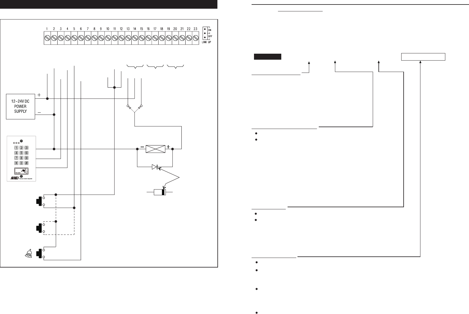
16
APPLICATION EXAMPLES
1) BASIC WIRINGS OF A SPLIT-DECODED DOOR LOCK
NOTE:
• Connect the 1N4004 as close as possible to the lock in parallel with the lock power terminals of the lock to absorb
the back EMF to prevent it from damaging the keypad. The 1N4004 is not required if the electric lock is AC operated.
• To avoid Electro-Static-Discharge from interfering with the operation of the keypad, always ground the (
-
) terminal
of the keypad to earth.
• Always connect DOOR SENSOR terminal to (
-
) ground if not used.
• Always connect TAMPER terminal to (
-
) ground if not used.
• Make 3-wire Connection (+,
-
, DATA I/O) to the keypad in the DK-2800 series. More than one keypads can be
connected in parallel.
-
ALARM O/P
-
KEY ACT O/P
-
N.O.
-
COM
-
N.C.
-
N.O.
-
COM
-
N.C.
-
N.O.
-
COM
-
N.C.
-
TAMPER
-
GND(
-
)
-
DOOR SENS
-
O/P 1 INHIB
-
INT. LOCK
-
DU OUT
-
DOOR BELL IN
-
EG IN
-
DATA I/O
-
KEYPAD PWR
-
GND(
-
)
-
12-24V DC
N.O.
ELECTRIC LOCK
1N4004 CATHODE
OUTPUT RELAY 1
N.O. Output for Fail-secure Lock
N.C. Output for Fail-safe Lock
N.C.
OUTPUT 1 OUTPUT 2 OUTPUT 3
DIGITAL KEYPAD
AD-1312 OR AP-960
EGRESS BUTTON
MORE EGRESS
BUTTON CAN
BE CONNECTED
IN PARALLEL
DOOR BELL
BUTTON
N.O.
(
-
)
(
-
)
(
-
)
N.O.
N.O.
RECORD-DELETE PINS OR CARDS FOR OUTPUT 1, 2, & 3 (Locations 10, 20 & 30)
Total of 1,200 User PINs and/or Cards are available for the 3 user groups to control the 3 outputs.
1) 1,000 ---- for Output 1 (Group 1)
2) 100 ------ for Output 2 (Group 2)
3) 100 ------ for Output 3 (Group 3)
The Private User PINs and Cards in the 3 user groups MUST be unique. Repeated PINs will be rejected. Secondary User
PINs in the “EM Card + Secondary User PIN” can be repeated. See the Important Note --- Programming Criteria for
Codes in page 14 for more information.
USER GROUP LOCATIONS
– Group 1 --For User PINs/Cards Controlling Output 1
1,000 Users are allowed in group 1 for O/P 1
– Group 2 --For User PINs/Cards Controlling Output 2
100 Users are allowed in group 2 for O/P 2
– Group 3 -- For User PINs/Cards Controlling Output 3
100 Users are allowed in group 3 for O/P 3
SELECTION OF OPERATION MEDIA
Number 1, 2, 3 or 4 represents the Media to be used to operate the keypad.
Number 5 is the authorization code for deleting of an PIN and/or Card from
its User ID.
= EM Card only; = Private User PIN only;
= EM Card + Secondary User PIN = EM Card + Common User PIN
= Delete an User PIN &/or Card from the selected User ID number
= Clear all the PINs & Cards from the selected Location. It takes
few seconds to a minute to complete depending on the Location
selected and the data stored.Please see the programming example
below for the details.
USER ID NUMBER
A 3-digit ID is an identified number for each User PIN and/or Card.
Repeated ID number will be rejected by the system
a) ID Number 000
-
999 for 1,000 User PINs/Cards to operate Output 1
b) ID Number 001
-
100 for 100 User PINs/Cards to operate Output 2
c) ID Number 001
-
100 for 100 User PINs/Cards to operate Output 3
CARD &/OR USER PINS
The User PINs can be 4-8 digits. Key in the User PIN on each ID Number box, then confirm it with # key
Just simply put the EM card close to the reader window to read it on each ID Number box, then, confirm it with
# key if it is a Card ONLY, or Card + Common User PIN entry. The Common User PIN is NOT required to key-in
here. It will go into its location automatically after the Card is read.
Read the Card first, then key in the Secondary User PIN on each ID Number box, then confirm it with # key if it
is Card + Secondary User PIN. The Secondary User PINs can be duplicated or a proprietary User PIN but can
not be a duplicate of a Prime Code. Owner can use the same secondary User PIN for a group of Cards as a group
Common User Code (or called Department Code) for a specific relay output.
Cards (Operation Media # 1, 3, & 4) and Private User PINs (Operation Media 2) MUST be unique. A repeated EM
card or Private User PIN will be rejected and one long beep will be generated by the system to notify the owner.
10
-
30 1
-
5 000
-
999 #
10
20
30
1 2
3 4
5
0999
CARD &/OR USER PIN VALIDATIONLOCATIONS MEDIA USER ID
CARD &/OR USER PIN
27
INDIVIDUAL
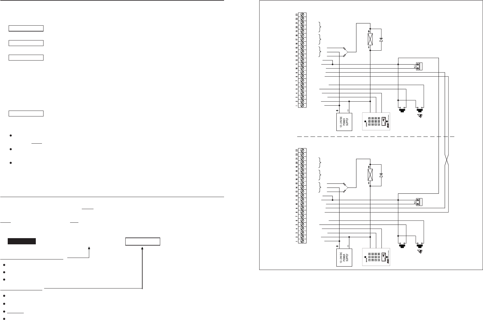
17
2) BASIC WIRINGS OF AN INTER-LOCK SYSTEM USING TWO SPLIT-DECODED KEYPADS
An inter-lock system needs two door controllers. This application example uses two keypad systems with simple cross
wire connection on their "Output 1 Inhibit" and "Inter-lock Control Output" terminals. It is necessary to link up the "(
-
)
GND" terminals of the two keypads as common ground to achieve the inter-lock logical functions.
• Use keypad to open the door from outside
• Press egress button to open the door from inside
• Connect the door magnetic sensors on the doors to monitor their positions
• While door 1 is open, then, door 2 is forced to keep close, or vice versa
• Use N.O. Relay output for fail-secure lock; and N.C. output for fail-safe lock
• Please also see the "NOTE" stated in the Application Example (1)
-
ALARM O/P
-
KEY ACT O/P
-
N.O.
-
COM
-
N.C.
-
N.O.
-
COM
-
N.C.
-
N.O.
-
COM
-
N.C.
-
TAMPER
-
GND(
-
)
-
DOOR SENS
-
O/P 1 INHIB
-
INT. LOCK
-
DU OUT
-
DOOR BELL IN
-
EG IN
-
DATA I/O
-
KEYPAD PWR
-
GND(
-
)
-
12-24V DC
N.O.
ELECTRIC LOCK
1N4004
DOOR 1
OUTPUT RELAY 1
N.O. Output for Fail-secure Lock
N.C. Output for Fail-safe Lock
N.C.
OUTPUT 1 OUTPUT 2 OUTPUT 3
DIGITAL KEYPAD
AD-1312 OR AP-960
EGRESS BUTTON
DOOR BELL
BUTTON
N.O.
(
-
)
(
-
)
N.O.
DOOR 1
SENSING
COMMON GROUND
(
-
)
DA-2800 OR DA-2801 DA-2800 OR DA-2801
CROSS WIRE CONNECTION FOR INTER-LOCK FUNCTIONS
-
ALARM O/P
-
KEY ACT O/P
-
N.O.
-
COM
-
N.C.
-
N.O.
-
COM
-
N.C.
-
N.O.
-
COM
-
N.C.
-
TAMPER
-
GND(
-
)
-
DOOR SENS
-
O/P 1 INHIB
-
INT. LOCK
-
DU OUT
-
DOOR BELL IN
-
EG IN
-
DATA I/O
-
KEYPAD PWR
-
GND(
-
)
-
12-24V DC
N.O.
ELECTRIC LOCK
1N4004
DOOR 2
OUTPUT RELAY 1
N.O. Output for Fail-secure Lock
N.C. Output for Fail-safe Lock
N.C.
OUTPUT 1 OUTPUT 2 OUTPUT 3
DIGITAL KEYPAD
AD-1312 OR AP-960
EGRESS BUTTON
DOOR BELL
BUTTON
N.O.
(
-
)
(
-
)
N.O.
DOOR 2
SENSING
OPERATION AND FUNCTIONS OF THE SUPER USER PIN
1) Operate Output 1, 2, and 3
The operation of the Super User PIN is just like a normal User PIN. Simply key-in the PIN with a specific output
number for the desired Output. The Super User PIN can also be used to reset an operating output timer instantly.
---------- Output 1 Activates or Output 1 Resets
---------- Output 2 Activates or Output 2 Resets
---------- Output 3 Activates or Output 3 Resets
2) Inhibit The User PINs For Output 1
The Super User PIN can also be used to inhibit the normal User PINs/Cards for the Output 1 (usually they are for
door strike). It enhances the security level of the access control system, such as to stop a keypad after office hour
or while the house is nobody inside. Once the Output 1 is inhibited, the User PINs/Cards for it become invalid and
those people even know the User PINs are refused during the system is inhibited. The inhibit function is toggled in
Start / Stop mode with the following code entry.
---------- The Whole Group of User PINs & Cards for Output 1 are Disabled
or Enabled in Toggle
NOTE:
The inhibit function setting with the Super User PIN applies to the whole group of User PINs and Cards for
Output 1 ONLY, but not for Output 2 or Output 3.
For safety reason, the inhibit function initiated with the Super User PIN does not govern the Egress Button. The
door still can be opened with it from inside.
The Super User PINs are always valid. They are not governed by any inhibit or lock out function in the system.
RECORD THE COMMON USER PINS FOR OUTPUT 1, 2 & 3 (Locations 03, 04, & 05)
The Common User PINs 1, 2 and 3 are prepared for operating of the Output 1, Output 2 and Output 3 respectively as
an enhance code. The Common User PINs MUST work in the form of “Card + Common PIN” to operate the outputs to
increase the security of the access control system. See Locations 10, 20 & 30 for more information.
NOTE : Common User PIN alone can NOT be used to operate the Outputs directly.
COMMON USER PIN LOCATIONS
-- Location Stores The Common User PIN for Output 1
-- Location Stores The Common User PIN for Output 2
-- Location Stores The Common User PIN for Output 3
COMMON USER PINS
The Common User PIN can be 4 to 8 digits. Press # key to confirm the code entry.
When a new Common User PIN is keyed in and confirmed, the old one is replaced.
Example: Set a Common User PIN with the number of “1 3 5 7” for Output 1 ----
To deleted a Common User PIN from memory: Key in just the Location number and #. ----
4 to 8 Digits
SUPER USER PIN
SUPER USER PIN
SUPER USER PIN
SUPER USER PIN
COMMON USER PIN VALIDATIONLOCATIONS
# 1
# 2
# 3
# 9
03 1357 #
03 #
03
04
05
#
03
-
05
26
INDIVIDUAL
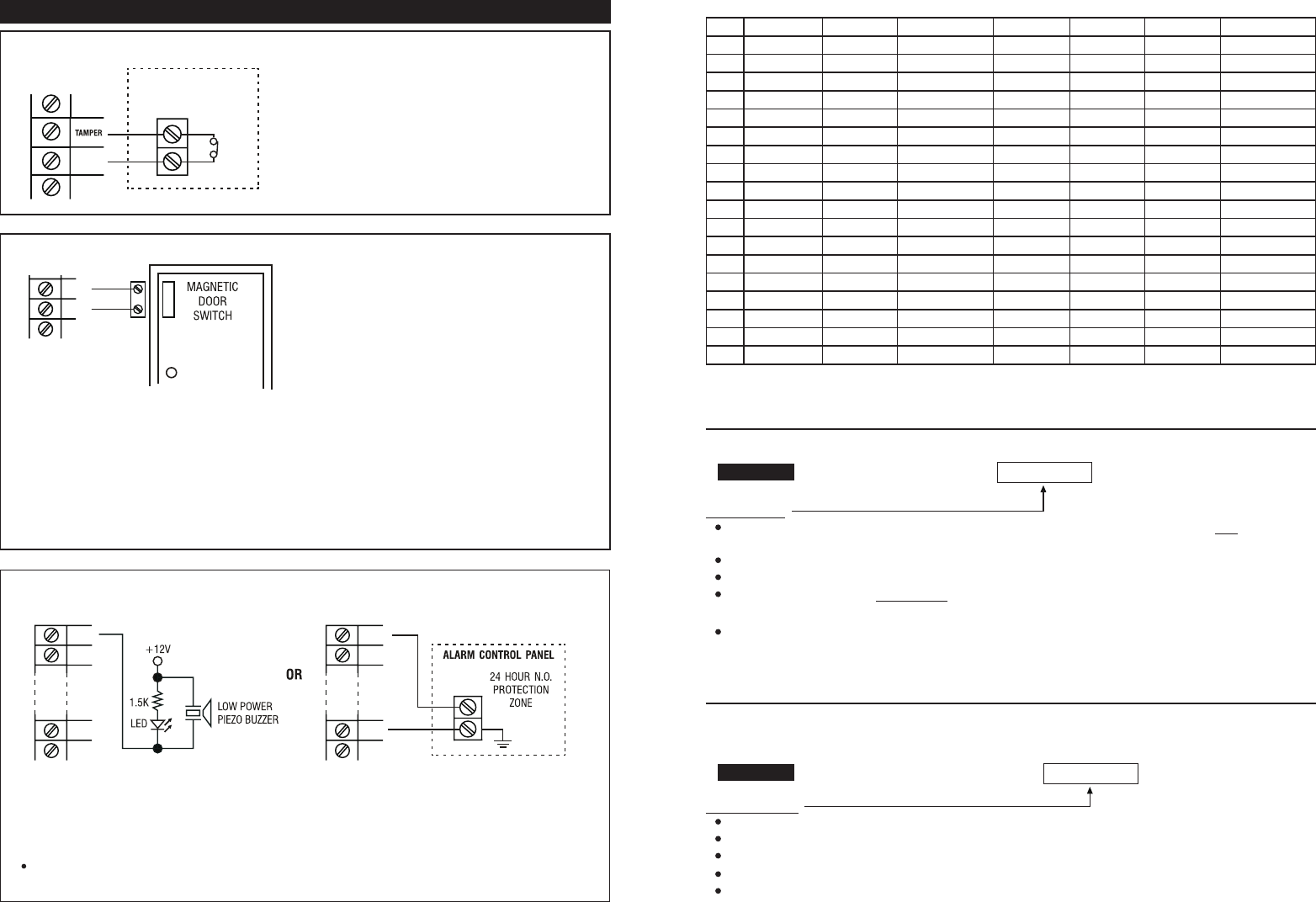
APPLICATION HINTS FOR THE AUXILIARY TERMINALS
The tamper switch is Normally Closed while the keypad
is secured on the gang box. It is open when the keypad
is removed from the gang box. To get warning at
sabotage, connect the tamper switch to the TAMPER
terminal of the DA-2800. If more than one tamper
switches are connected, just connect them in series.
With the help of a Normally Closed door
position sensor (usually a magnetic door
switch) on the door to set up the following
functions:
Door Auto Relock -- The system will immediately
relock the door after a valid access has been gained to
prevent "tailgate" entries.
Door Forced-open Alarm -- The keypad will generate
alarm instantly if the door is forced to open. Enable the
function at Location 80.
Door Propped-up Alarm -- The keypad will generate
alarm if the door is left open longer than the pre-set
delay time. Enable the function at Location 81.
Inter-lock Control -- When the door is open, the
interlock output of the keypad will give a (
-
) command
to stop the other keypad in an inter-lock system.
Door Opening Alarm -- Door Opening Alarm is
designed for the emergency door only. It is always
given when the door is opened unless a valid user code
or card is used prior to the door is opened. Enable the
function at Location 91.
a)
b)
c)
d)
e)
(A) TAMPER N.C.
(B) DOOR SENS
The Alarm Output switches to (
-
) ground in door forced to open or the door open after Egress Delay. You may
use it to turn ON an LED lamp and/ or a small buzzer to notify a guard; or connect it to a 24 hour Normally
Open protection zone of an alarm system. See Location 80 and Location 91 for more information about these
functions.
Only one connection option is recommended. Make sure that the sink current does not exceed the maximum
rating of 100mA.
(C) ALARM OUTPUT
GND(
-
)
N.C
TAMPER SWITCH
OF THE KEYPAD
GND(
-
)
DOOR
SENS
18
ALARM
O/P
KEY ACT
O/P
GND
(
-
)
ALARM
O/P
KEY ACT
O/P
GND
(
-
)
Example:
User Name Location Function Code User ID PIN/Code Card # Remark
1
2
3
4
5
6
7
8
9
10
11
12
13
14
15
16
--
1,000
RECORD A MASTER CODE --For Both Master & Slave Keypads (Location 01)
MASTER CODE
Master Code is the authorization code for setting the system to programming mode. It is NOT an User Code
operating of the output relays.
The Master Code can be 4 to 8 digits. Press # key to confirm code entry
When a new master code is keyed in and confirmed, the old master code is replaced automatically.
The master code is also the Link-up Code between the keypad and the controller of the system in Split-decoded
operation. Master and Slave Keypads are required to set with the same Master Code.
Example: Set a Master Code with the number of “2 2 3 3” ----
RECORD A SUPER USER PIN (Location 02)
The Super User PIN has TWO functions. It is prepared for the owner to simply use only one User PIN to operate the
three outputs of the keypad and make operation inhibit enable / disable to the system outputs.
SUPER USER PIN
The Super User PIN can be 4 to 8 digits.
Two beeps will be heard after pressing the # key to confirm code entry.
When a new Super User PIN is keyed in and confirmed, the old one is replaced.
Example: Set a Super User PIN with the number of “2 5 8 0” ----
To deleted a Super User PIN from memory: Key in just the Location number and #. ----
4 to 8 Digits
SUPER USER PIN VALIDATIONLOCATION
02
02 2580 #
02 #
#
4 to 8 Digits
MASTER CODE VALIDATIONLOCATION
01
01 2233 #
#
25
INDIVIDUAL
INDIVIDUAL
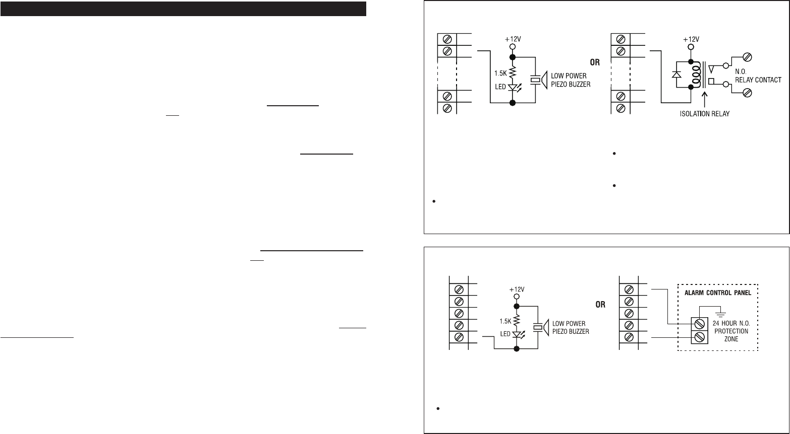
The Duress Output switches to (
-
) ground when duress code is entered. You may use it to turn ON an LED
lamp and/ or a small buzzer to notify a guard; or connect it to a 24 hour Normally Open protection zone of an
alarm system.
Only one connection option is recommended. Make sure that the sink current does not exceed the maximum
rating of 100mA.
(E) DURESS OUTPUT
The Key Active Output switches to (
-
) ground for 10
seconds whenever a key is touched. You may use
it to turn ON an LED lamp and /or a small buzzer to
notify a guard; or to energize a relay to switch ON
lights or trigger an CCTV Camera to start recording.
Make sure that the relay for switching ON lights
has high enough isolation between high voltage
and low voltage to prevent damage of the keypad.
Only one connection option is recommended. Make
sure the sink current does not exceed the maximum
rating of 100mA.
External power supply and isolation relay are strictly
necessary in driving high power device, such as
lights.
(D) KEY ACTIVE OUTPUT
(a) (b)
GND
(
-
)
DOOR
SENS
O/P 1
INHIB
INT.
LOCK
DU
OUT
GND
(
-
)
DOOR
SENS
O/P 1
INHIB
INT.
LOCK
DU
OUT
19
ALARM
O/P
KEY ACT
O/P
GND
(
-
)
ALARM
O/P
KEY ACT
O/P
GND
(
-
)
FEATURE PROGRAMMING -- KEY IN AND STORE THE DESIRED VALUES
The feature values can be set and stored into the system one by one with the desired Programming Locations.
Programming can be made continuously and it is not necessary to be in sequence order. Just go to the desired
programming location and key in the value for the desired feature.
IMPORTANT NOTE --- Programming Criteria for Codes:
a) The Prime Codes:
All the Private User PINs, Master Code, Duress Codes, Super User PIN, Common User Codes and the Visitor User
Codes belong to Prime Codes in the system. They have the priority to be read and they MUST be unique and can not be
repeated in the programming. A Prime code also can NOT be duplicated for Secondary code to work with the EM Card
or vice versa.
b) The Prime Cards:
All the EM Cards used in this system are Prime Cards. The cards used for the Outputs 1, 2 and 3 MUST be unique and
can not be repeated use for different Outputs in the programming. The Card always has the priority to be read when
working in “EM Card + Secondary PIN” or "EM Card + Common User PIN”.
c)Warning for A Repeated Use of Prime Code or Card:
One long beep is given if a Code/PIN is keyed in or a Card is read. It means that a Prime Code or a Prime Card is
repeated. The Code/PIN or Card was already in one of the PIN or Card Locations or IDs. The programming is invalid.
Change a new Code/PIN or Card and program it again.
d)Secondary User PINs:
The Secondary User PINs are prepared to enhance security. It is put after a Card in “EM Card + Secondary User PIN”
programming. They can be a repeated code within the Secondary PINs but it is NOT allowed a duplicate of the Prime
Codes. The system will reject a duplicated Prime Code for Secondary User PIN or vice versa.
e)Getting Advantages from The Secondary User PINs:
The repeated Secondary PINs can be used as a Group Common User Code or called Department User Code for a group
of EM Cards, which simplifies the programming of using large number of different User PINs. EM Card with Department
Code prevents a lost card used by people of other department. Also, it will be easier to trace out the department of the
lost card belongs to. Of cause, the owner can use a proprietary Secondary User PIN for each EM Card in the “EM Card
+ Secondary User PIN” programming to further increase the security if it is the main concern.
f) Security Level Comparison of The Secondary User PIN/Code following Card Reading:
i) EM Card + Common User Code --- All EM Cards use the same User Code. Security level is better than just Card
only. A lost Card picked up by any people can be used if he knows the Common User Code.
ii) EM Card + Department User Code --- The EM Cards are divided into groups with a Department User Code. A lost
Card can be used only by the people in the same group who know the Department Code.
iii) EM Card + Secondary User PIN --- Each EM Card has its own proprietary User PIN. A lost Card can not be used
by other people.
NOTE:
Each EM Card is a Prime card and it has the priority to be read. The system provides the proprietary Wiegand Data
output from each card only. The Secondary PIN/Code following the card reading does not affect the ID of the Card in the
Wiegang Data.
g) Make A List Recording of The User Names VS User Codes:
Suggest the owner to make a list recording of the User Names corresponding to the Codes/PINs/Cards that are going to
store in the Locations and the IDs before the programming. It will be a useful tool for the owner to easily program them
smoothly and also to trace them from this multi-users system in the future.
Example: (Please see the following page)
24
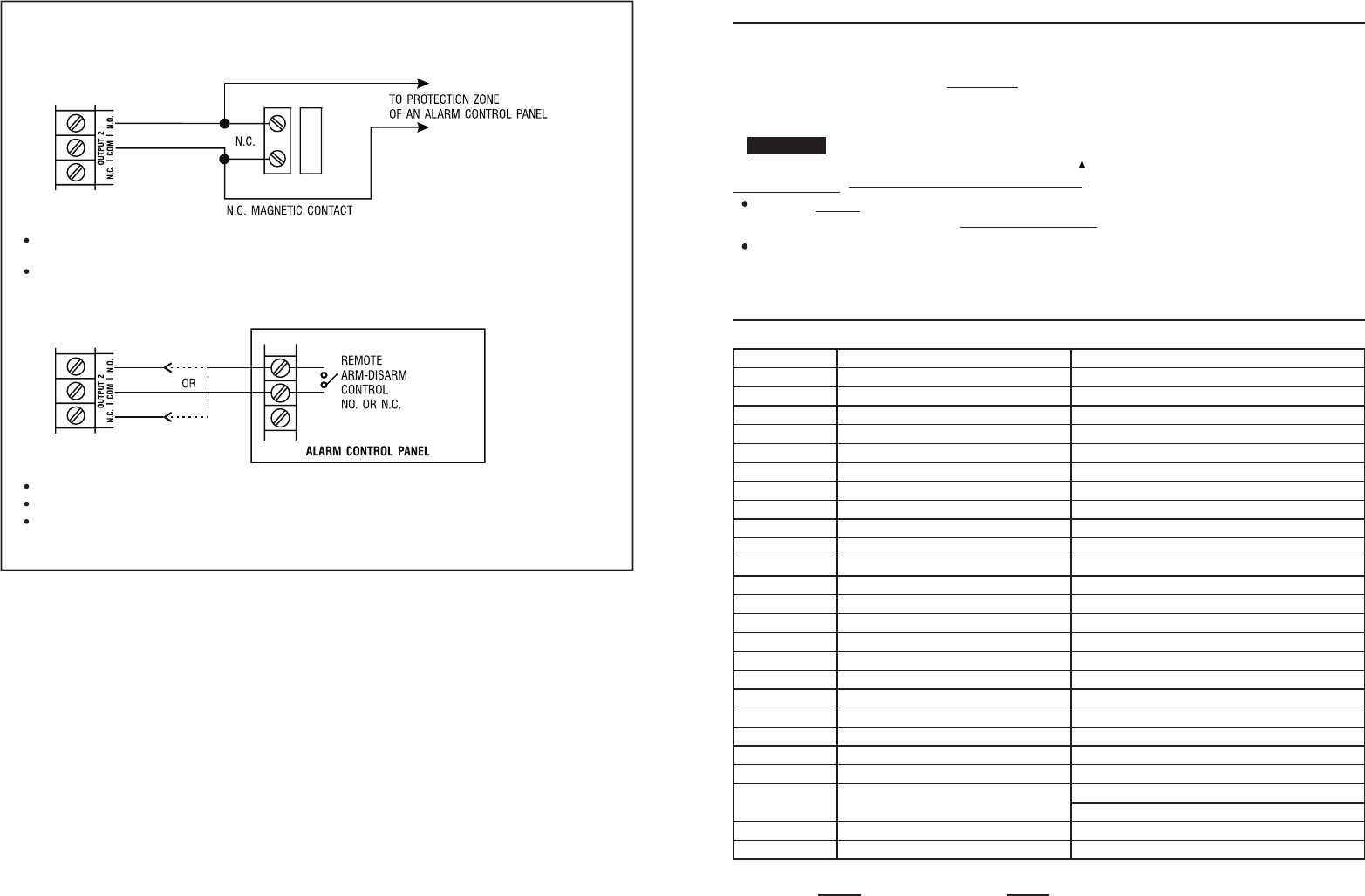
20
Use the Normally Open (N.O.) output contact to shunt a Normally Closed (N.C.) protection zone of an alarm
system.
Set output contact to Start / Stop Mode (Programming Option 52, Output Mode=0).
Use the (N.O.) or (N.C.) output contact to make arm-disarm control of an alarm system.
Consult your alarm control panel manual for the appropriate output contact to be used in arm-disarm control.
Usually set output 2 to Momentary mode (Programming Option 521, Location 52, Output Mode=1) for multi
station systems and Start / Stop mode (Programming Option 520, Location 52, Output Mode=0) for single
station systems.
(F) OUTPUT 2 OR OUTPUT 3
( i ) Shunting an N.C. Zone
( ii ) Alarm System Arm-Disarm Control
REFRESH THE SYSTEM WITH THE “REFRESHING CODE” --- 9 9 9 9
The system can be refreshed to clear all the old data stored and back to its ex-factory default values.
IMPORTANT NOTE:
Make sure that you really want to clear ALL the OLD data before entering of the Refreshing Code. The keypad will be
back with its default values like a new unit. Re-program of the desired values are necessary.
REFRESHING CODE
The Code 9 9 9 9 is for refreshing of the system. Once it is keyed in and validated with #, all the values
programmed previously will be cleared EXCEPT the Master Code.
The refreshing takes around 2.5 minutes. During the keypad is being refreshed the Status LED (Amber) flashes fast
until the end.
THE DEFAULT VALUES OF THE KEYPAD
PROGRAMMING
LOCATION PARAMETERS DEFAULT FUNCTIONS & VALUES
0 1 Master Code 0 0 0 0 Factory Set, Not a default value *
0 2 Super User PINs Nil ----- User Program Required
0 3 Common User PIN 1 Nil ----- User Program Required
0 4 Common User PIN 2 Nil ----- User Program Required
0 5 Common User PIN 3 Nil ----- User Program Required
1 0 User PINs & Cards for O/P 1 Nil ----- User Program Required
2 0 User PINs & Cards for O/P 2 Nil ----- User Program Required
3 0 User PINs & Cards for O/P 3 Nil ----- User Program Required
4 0 Visitor Codes Nil ----- User Program Required
4 1 Duress Code for O/P 1 Nil ----- User Program Required
4 2 Duress Code for O/P 2 Nil ----- User Program Required
4 3 Duress Code for O/P 3 Nil ----- User Program Required
5 1 O/P Mode of The O/P 1 Time = 5 Sec, Momentary
5 2 O/P Mode of The O/P 2 Time = 5 Sec, Momentary
5 3 O/P Mode of The O/P 3 Time = 5 Sec, Momentary
6 0 Personal Safety & Lock-out Code = 1, 10 False Code/Card Lock-out 60 Sec
7 0 User Code Entry Mode Code = 2, Manual Entry Mode
7 1 Pacifier Tones ON-OFF Selection Code = 1, Pacifier Tone ON
7 2 O/P Operation Announcer Code = 1 Sec, Notification Beep ON
7 3 Status LED Standby Flashing ON-OFF Code = 1, Flashing Enabled
8 0 Door Forced Open Warning & Timing Code = 0, Warning Disabled
8 1 Door Propped-up Warning & Delay Code = 0, Warning Disabled
9 0 Egress Delay & Warning Code 1 = 0, Instant, No Delay
Code 2 = 1, Momentary Contact without Warning
9 1 Door Opening Alarm & Timer Code = 0, Alarm O/P Disabled
9 4 Operation Modes & Wiegand Output Code = 0, Wiegand O/P for Valid Code/Card Only
NOTE:
The DAP Code 8 0 8 0 and the Refreshing Code 9 9 9 9 are fixed in the operating system program. It can not be
changed in any ways or be influenced by the system in default setting.
REFRESHING CODE VALIDATION
9999 #
23
INDIVIDUAL

PROGRAMMING FOR FULL FEATURES --- (Supplementary Information)
In the Split-decoded operation mode, the keypad becomes a data entry tool of the system and its Data I/O port always
gives full feature data to the decoder. A keypad of simplified version also gives full features in Split-decoded mode. You
may try to program the required features even from a simplest keypad to make a full feature system. The programming
information supplied here is for the convenience of the owner who does not own a full feature keypad.
A Split-decoded system with only one keypad is a Master keypad. Just simply program all the features into it.
In a Split-decoded system with Master and Slave keypads, the major features MUST be programmed into the Master
keypad. The controller will only take these features to operate the system.
The other features can be programmed into each keypad independently. Each individual keypad, no matter a Master or
Slave is required to program with its User PINs, Codes and Cards to operate.
Each Programming Location in this manual is highlighted with MASTER or INDIVIDUAL for the owner’s programming
convenience.
------- The features MUST be programmed into the Master Keypad.
--- The features required to be programmed into each keypad individually including the PINs, Codes and
Cards. Those features are used in that keypad only and they can be repeated use in the other
keypad(s) in the system.
REMARK:
• The feature of reading EM Cards only available on the keypads with EM Card reader.
• No keypad is supplied with the Access Controller. User has to purchase the keypad seperately.
• Only the keypads with DATA I/O port are compatible with the Access Controller.
SET SYSTEM INTO PROGRAMMING MODE WITH THE MASTER CODE
IMPORTANT NOTE:
1) DO NOT TURN OFF POWER while the keypad is in Programming Mode. Otherwise, it may cause data lost/error to the
programmed features in the memory.
2) The keypad beeps after power up. Wait 1 minute until the end of the power up delay, then key in the Master Code for
setting the system into programming mode.
3) For the owner’s convenience in programming at the first time, the factory has put a Master Code 0 0 0 0 into the
keypad (It is NOT a default code). To compromise security, in all cases, the owner should program a new Personal
Master Code to invalidate the factory set Master Code after the keypad is owned.
4) The Button has two functions in the keypads with Door Bell button. It is a door bell button while the keypad is in
normal operation; and it is equivalent to a * Button in programming mode.
MASTER CODE
The Master Code can be a factory set master code or the private master code that
was set by the owner.
Validate the master code with * * (or ) .
2-beep confirms a valid master code. The Mains LED (Amber) is constantly ON after the system is set in the
programming mode.
0000 **
MASTER CODE VALIDATION
.
. .
21
MASTER
INDIVIDUAL
INDIVIDUAL
DIRECT ACCESS TO PROGRAMMING MODE WITH THE “DAP” CODE – 8 0 8 0
Set System Into Programming Mode With DAP Code In Case Of The Master Code Is Forgotten ! !
The owner requires to apply the following procedures precisely to set the system into programming mode
with the DAP code 8 0 8 0.
1) Switch OFF all the power for 1 minute to ensure that the system is fully discharged.
2) Swich ON power again. The system is in Power-up Mode for 1 minute and the buzzer gives beeps during the whole
period. This is the only time limit for setting the system to Direct Access to Programming (DAP).
3) Press the Egress Button (EG IN) once first to enable the DAP function.
4) Key in the DAP Code 8 0 8 0 and validate it with * * (or ), the existing Master Code in the memory is
erased and the power up beep stops. The keypad turns itself into programming mode like using the Master Code and
it is ready to accept the new programming data.
5) If the Egress Button is not pressed and the DAP code is not keyed in within the power up period, the system will set
itself to normal operation mode. To set it back to power-up mode, repeat procedures 1-4.
DAP CODE
The DAP code is fixed on 8 0 8 0 and it is valid only in the Power-up Period after the Egress Button is pressed.
Validate the DAP code with the * * (or ).
2-beep confirms the system is in the Programming Mode; and the Mains LED is constantly ON.
See “RECORD A MASTER CODE” at “Location 01” for the details of programming a new master code.
NOTES FOR SPLIT-DECODED OPERATION:
1. It is necessary to press the Egress Button on the keypad unit once to enable the DAP function.
2. In Split-decoded mode, the Egress Button is connected to the controller unit but not to the keypad. The owner has
to use a short wire to make a momentary touch of the "EG IN" terminal of the keypad to "GND (
-
)" to simulate of
pressing the Egress Button in order to enable the DAP function.
3. This procedure is required for both Master keypad and Slave keypad in Split-decoded operation with DAP Code going
into programming mode.
8080 **
DAP CODE VALIDATION
.
.
.
.
EGRESS BUTTON
PRESS ONCE
22
INDIVIDUAL