AGD SYSTEMS 342100 AGD342-100-xxx Speed Enforcement Ranging Radar User Manual 342PM ISS07 indd
AGD SYSTEMS LTD AGD342-100-xxx Speed Enforcement Ranging Radar 342PM ISS07 indd
UserManual.wiki
>
AGD SYSTEMS
>
342100 User Manual
User manual
Navigation menu
Upload a User Manual
Namespaces
Wiki Guide
HTML
PDF
Info
Views
User Manual
Discussion / Help
Navigation
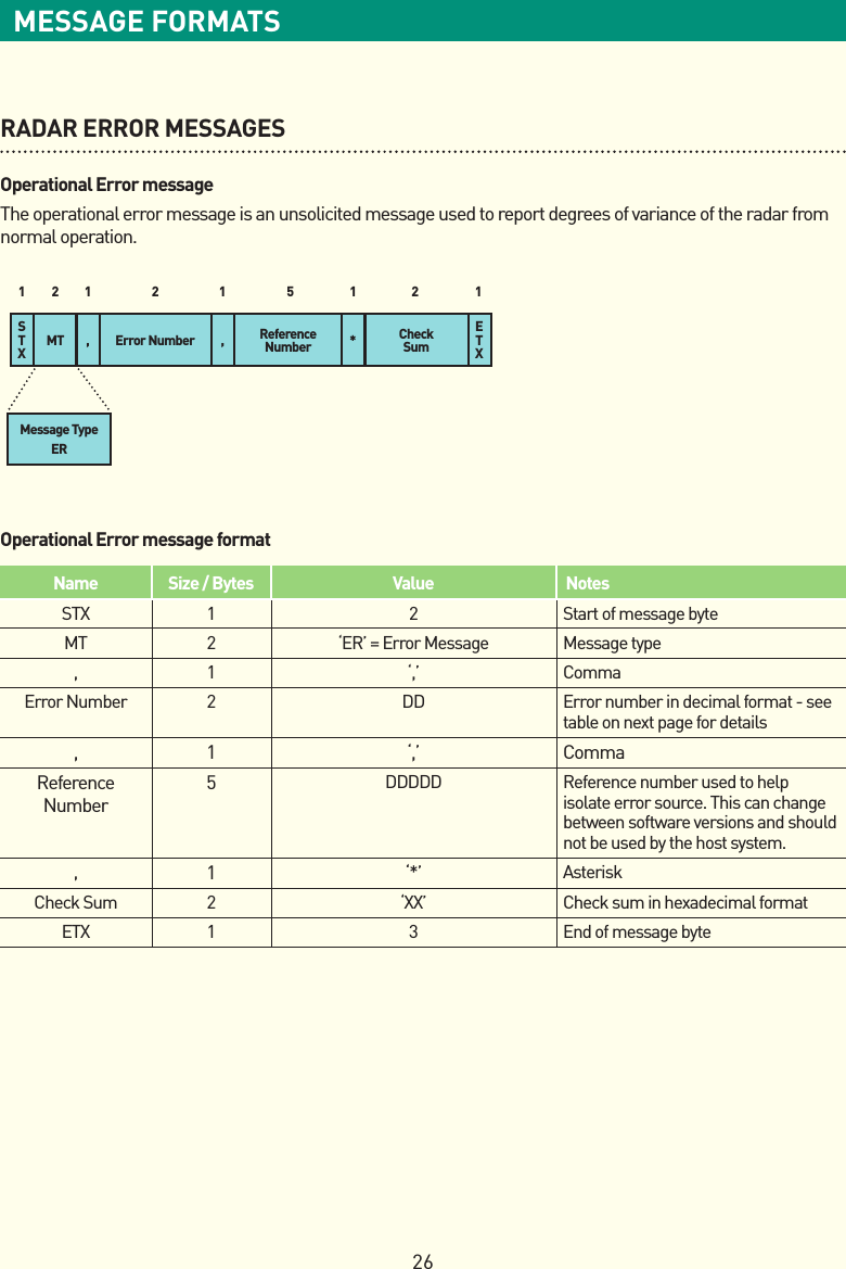
![28CRC8 C CODE WORKED EXAMPLECRC8 C CODECRC8 checksums are used on the standard radar messages. The checksum calculation is performed on all bytes, up to and including the asterisk character. These checksums are calculated using the following C code.//Lookup table for CRC8 calculation//Needs to be initialised with InitCRC8U8 crc8_table[256];/********************************MemCRC8*******************************This function calculates the CRC8 of a data array pointed to by dataand of length length.Usespolynomialx^8+x^2+x+1.Lookuptableusedbyfunctionisinitialisedby the InitCRC8 function.*/unsignedcharMemCRC8(void*data,unsignedintlength){unsigned char crc8;unsigned char i;unsigned char *dptr; dptr=(unsignedchar*)data; crc8 = 0; //Start with a value of 0 for(i=0;i<length;i++) { crc8 = crc8_table[crc8 ^ *dptr]; ++dptr; } return crc8;}#deneGP0x107/*x^8+x^2+x+1*/#define DI 0x07/****************************InitCRC8******************************Initialises the lookup table for the MemCRC8 functionUsespolynomialx^8+x^2+x+1*/voidInitCRC8(void){int i,j;unsigned char crc; for(i=0;i<256;i++) { crc = i; for(j=0;j<8;j++) { crc=(crc<<1)^((crc&0x80)?DI:0); } crc8_table[i] = crc & 0xFF; }}](https://usermanual.wiki/AGD-SYSTEMS/342100/User-Guide-1907178-Page-28.png)