AGD SYSTEMS 342100 AGD342-100-xxx Speed Enforcement Ranging Radar User Manual 342PM ISS07 indd
AGD SYSTEMS LTD AGD342-100-xxx Speed Enforcement Ranging Radar 342PM ISS07 indd
User manual
ISO 14001
Registered
Environmental
Management015
ISO 9001
Registered
Quality
Management015
PRODUCT MANUAL
©AGD Systems Limited 2013 Doc. Ref. 342 PM ISS8

2
INTRODUCTION
Product & technology 3
Key features 3
Typical applications 4
Product overview 4
INSTALLATION
Radar mounting geometry 5
Radar mounting height 6
Selecting a suitable site 6
Radar in normal operation 6
SYSTEM HARDWARE OVERVIEW
System hardware overview 7
RS422 serial interface 8
Temperature sensor 8
Power supply 9
Radar characteristics 10
SOFTWARE FUNCTIONALITY
Overview 11
RADAR COMMANDS
Radar Commands 12
Radar Command list 13
*TS Command & Hardware self-test 14-15
*SR Command & the 50KHz Reference Clock 16
*IQ Port Command 16
MESSAGE FORMATS
Event Start message 17
Event End message 18-19
Heart Beat message 20
Tuning Fork message 21
Event Quality message 22-23
Radar messages in normal operation 24
Explanatory notes for radar event & quality messages 25
Radar Error messages 26-27
CRC8 C CODE WORKED EXAMPLE 28
ANTENNA PLOTS 29
TECHNICAL SPECIFICATIONS
Product specification 30
TEST & CALIBRATION
Dedicated test equipment 31
MANUFACTURING TEST PROCESS
Hyperion Test Equipment 32
END OF LIFE – DISPOSAL INSTRUCTIONS (EOL) 33
IMPORTANT SAFETY INFORMATION
Safety precautions 34
Low power non-ionising radio transmission and safety 35
DISCLAIMER 36
Warranty 36
TABLE OF CONTENTS
3
INTRODUCTION
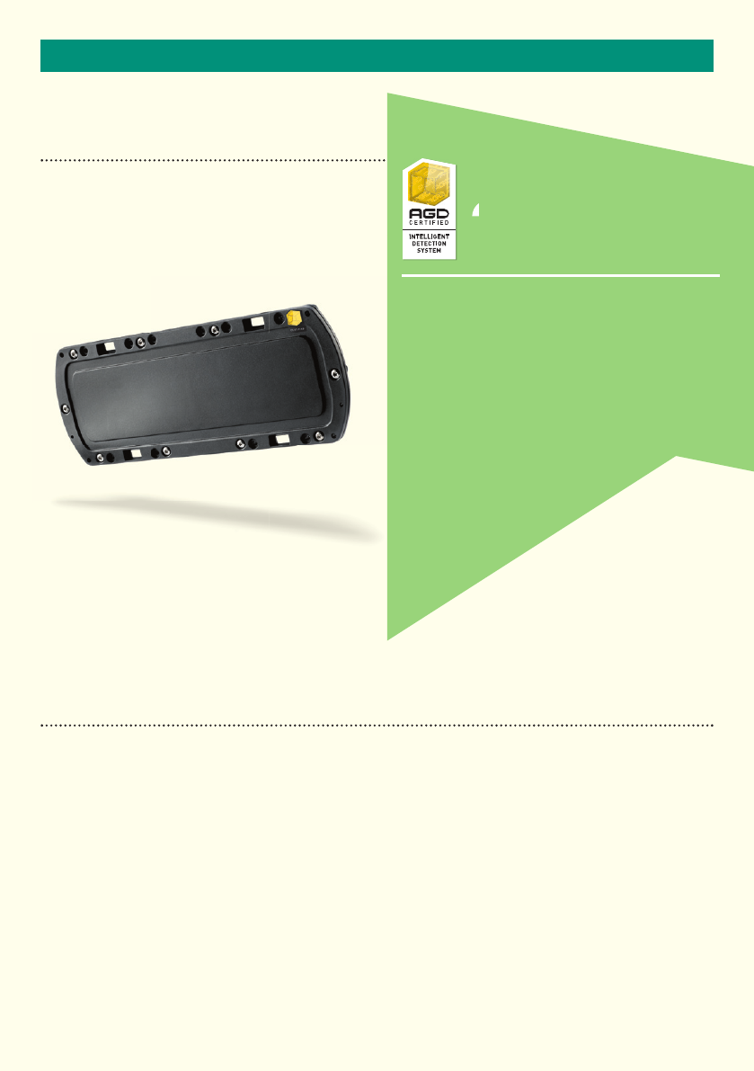
PRODUCT & TECHNOLOGY
KEY FEATURES
•Radarreportsspeedandrangetoeachevent
•Speedmeasurementfrom20kphto320kphacrossmultiplelanes
•Targetrangemeasurementfrom2-60metres
•Candiscriminatebetweenapproachingandrecedingtrafc
•Customdesignedplanarantenna
•Easeofintegrationtohostsystem
•HighspeedRS422serialcommunicationstohostequipment
•Hardwaretargetsimulationbuiltintotheradar
•Continuousradarselfcheckfeatures
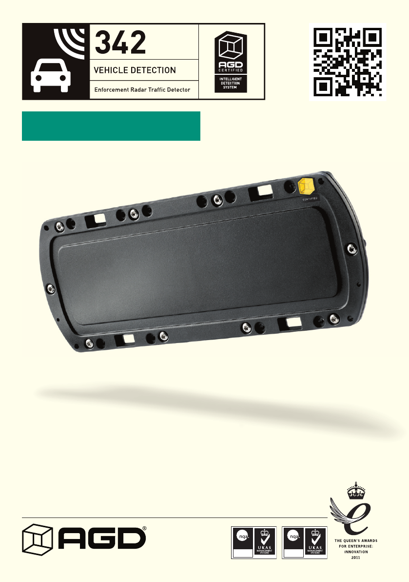
342
The 342 has been designed specifi cally to measure
the speed and range of passing vehicles for
enforcement purposes in multiple lanes. The radar
is able to track up to eight target signals in both
approaching and receding directions simultaneously.
The radar offers fi xed and mobile deployment
options in conjunction with a host photographic
based enforcement system.
342
4
INTRODUCTION
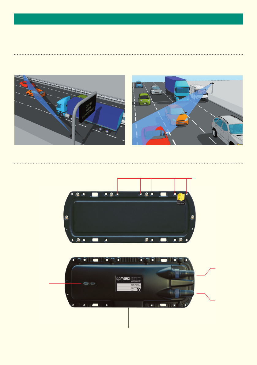
TYPICAL APPLICATIONS
Multiple lane control from fi xed infrastructure Multiple lane control from mobile systems
PRODUCT OVERVIEW
Tripod mounting point
Flange mounting points
Power
Low / High
LED
Power/Test
connector
RS422 Data
connector
5
INSTALLATION
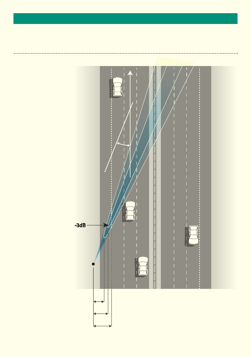
RADAR MOUNTING GEOMETRY
4976mm
4006mm
2747mm
-3dB
22º
22º
The radar is to be installed with the
bore of the radar at 22˚ from the
direction of travel of the targets in the
lanes. It can be installed at a height
in the range 1m to 5m with various
considerations. When installed,
especially if it is placed inside host
equipment, it is important that the
radar’s radome is not covered or
interrupted as this will distort the
radar’s beam and/or affect the
sensitivity of the radar.
The typical coverage of the radar is
shown in the following diagram.
342 Beam Analysis
Mounting Height: 4m
Mounting Angle: 7.5˚
below horizontal
Targets: vehicle refl ection
assumed from a height of 1m

6
INSTALLATION
RADAR MOUNTING HEIGHT
The radar can be installed at different heights but operation is best in the height range 1m to 3.5m. The radar
can be mounted up to a height of 5m but it is important to understand that at these higher mounting heights the
vertical cosine will affect the speed reading of the radar to progressively under-read for increasing heights for
lanes that are too close to the radar.
It is therefore recommended that a minimum off-set, that is, a minimum perpendicular distance from the
mounting position to the nearest enforceable lane is adopted as shown in the following table.
SELECTING A SUITABLE SITE
When choosing to deploy the radar on a site the following is a non-exhaustive list of considerations which should
be taken into account;
•Dothelane(s)haveameasurableradiuswhichcausethevehiclestotravelonanarcaroundtheradar?
•Doestheroadssurfaceslopeinadirectionexcessivelywhichmeansdeploymentisnotpossibleor
needs to be accounted for in the set-up/alignment process of the radar.
•Isthenearestlanetobecoveredgreaterthanthespeciedoffsetgiventheproposeddeploymentheight
fortheradar?
•Arethereanylargereectingsurfacesdirectlyinfrontorbehindtheradarmountingposition?
RADAR MESSAGES IN NORMAL OPERATION
When the radar is installed and aligned correctly it will perform to specification.
Mounting Height Minimum
Offset
Radar Declination Angle Comment
1-2m 2m 0º
3m 3m 0º
4m 4m 7.5º TBC
5m 6m 7.5º TBC
7
SYSTEM HARDWARE OVERVIEW
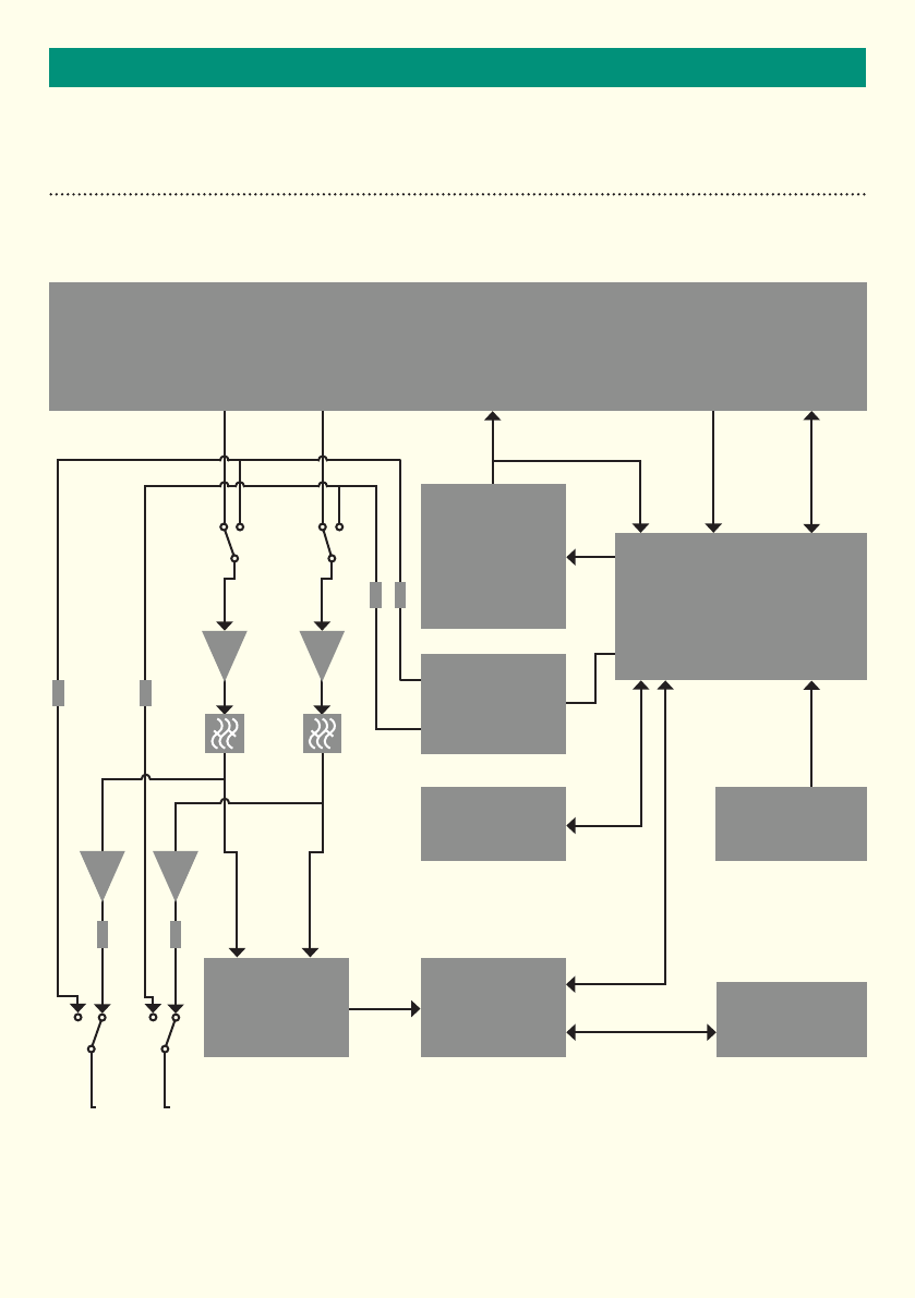
SYSTEM HARDWARE OVERVIEW
Microwave Transceiver Module
I Q Vt M PLL
Transmitter
Modulation
Control
Co-processor
Target
Simulator
Non Volatile
Memory
Digital Signal
Processor
Analogue
to Digital
Converters
Test Connections
I Q
Temperature
Sensor
RS422

8
SYSTEM HARDWARE OVERVIEW
RS422 SERIAL INTERFACE
A UART interface is provided that uses RS422 voltage levels on the communications connector. The default baud
rate for this interface is 115200. This however maybe changed using the *BAUD command to speeds of up to
926000. The *BAUD command must be followed by a *PUS command to store the new value to non-volatile
memory. This new value will be used next time the radar reboots.
The serial interface default setup during normal operation is shown in table below.
The RS422 provides the primary output of the radar in the form of ASCII messages.
The communications connector is a Bulgin PXO412/08P connector, mating type PX0410/08S/6065.
The pin out of the connector is shown in the table below.
TEMPERATURE SENSOR
A temperature sensor has been installed in the radar. The temperature of the radar may be requested using the
*TEMP command.
default uart settings
Parameter Value
Baud rate 115200
Data bits 8
Parity bits odd
Stop bits 1
Flow control None
rs422 ConneCtor ConneCtions
Pin No Signal Description
1 A(RX+) RS422Signals
2 B(RX-)
3 Z(TX+)
4 Y(TX-)
5 Not connected
6 Not connected
7 GND Ground or 0V
8 Not connected

9
SYSTEM HARDWARE OVERVIEW
POWER SUPPLY
The radar is powered using a DC voltage in the range of 10 to 16 Volts. This is supplied on the power and test
connector. This connector is a Bulgin PXO412/06P mating type PX0410/06S/4550.
Reverse polarity protection is included in the design. The radar can take a large current during power up that is
of the order of amps which only lasts for ~1ms and as such should not affect most applications.
A thermal fuse with a 750mA rating has been installed to protect against electrical short circuit fault conditions.
Power-Up Sequence
Upon initialisation from power-up or *REBOOT the radar will respond with the following sequence of messages;
AGD SYSTEMS LTD AGD342 RANGING ENFORCEMENT RADAR
Firmware Version MI-146-2-P2
Firmware Compile Time 10:21:21 Dec 5 2012
Co-Processor Firmware MI-147-1,Nov 12 2012
........
HB,00000000*FD
Whilst the radar is carrying out its self-test functions a series of decimal points will appear. When finished the
radarwillreportaHeartbeat(HB)messagetoindicatetheradarhassuccessfullyinitialisedandisnormally
operating. The host system should not send the radar any messages whilst it is initialising. Messages should
be sent to the radar after the HB is received. The radar will always send an initial HB message after initialising
following power-up even when the HB message is turned off.
Power Supply Tolerance
The radar power supply is specified between 10 and 16Vdc. These are the limits applied on test and calibration.
The radar will operate outside this range but its operation is not specified. At 12V dc the current is 250mA.
When VSUPPLY<10Vdc(butenoughtopowertheradar)theLEDwillpermanentlyIlluminated.
When VSUPPLY>16Vdc(butbelowfuselimit)theLEDwillash.
power / test ConneCtor ConneCtions
Pin No Signal Description
1REF Reference frequency
RS422 voltage levels
2REF
3 I Do not connect.
I and Q port connections for directly
measuring received signal or for
simulated signal injection
4 Q
5VIN Supply voltage 10 to 16Vdc
6GND Supply ground

1010
IMPORTANTSYSTEM HARDWARE OVERVIEW
RADAR CHARACTERISTICS
The radar has been designed to have a specific set of functional characteristics which make it suitable for speed
measurements for enforcement applications.
Radar Antenna
The antenna design is a planar patch array with the following performance;
Operating Frequency Band and Power
ThetransmitterisaPhaseLockedLoop(PLL)controlledMMICbasedoscillator.Thedesigncondencemeans
that the nominal centre frequency of the transmission shall remain within a 10MHz window for the required
7 years for a radar functioning normally.
The change in frequency with temperature is measured to be ≤ ±1.21MHz over the operating temperature
range-20ºCto+60ºC.
The radar frequency and power is as follows;
Parameter Specified Notes
Horizontal Beam-width 4.5˚ -3dB(HPBW)
Vertical Beam-width 15˚ -3dB(HPBW)
Side-lobe Suppression >15dB
E-Field Horizontal Plane Polarised
Parameter Specified Notes
Operating Frequency Band 24.075 – 24.125 GHz
FrequencyModulation(FM) 9.4MHz
Power <100mW eirp
Field Strength Typically 450mV/m At 3m
ITU Code 9M4FXN
11
SOFTWARE FUNCTIONALITY
OVERVIEW
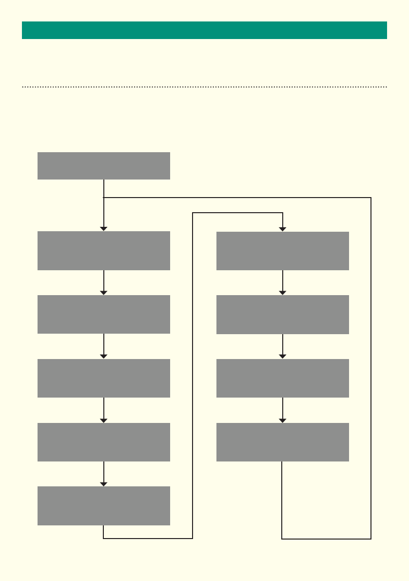
The 342 radar uses a real time operating system that continuously samples the input. The radar is continuously
performing a number of tasks simultaneously using a time multiplexing method. The main data capture and
processing task flow diagram is shown below.
Start
Data Capture
Perform FFTs
Find Range of Targets
Detect Possible Targets
in FFT Data
Remove Poor
Quality Targets
Add Accurate
Speed Measurement
Associate Detections
to Tracks
Tuning Fork Test
Process Track
Information (PTI)

12
RADAR COMMANDS
RADAR COMMAND OVERVIEW
Commands are used to control the operation of the radar. These are sent over the RS422 UART link.
Commands are immediately followed by an operator that indicates the required action. Not all operators are
supported for all commands. Where an operator is used and it is not supported the radar will respond with a
warning message. The table shows the operators that are used by the radar.
Operator Operation
= Set something to a value e.g. *LS=50<CR> sets low speed threshold to 50
? Respond with value or values
^ Set default value for parameter
$ Provide help on the command
! Do something e.g. *REBOOT! Reboots the radar
Command Operators
Where a command is used to enquire or set a radar parameter the radar will respond in a set way. The radar
will respond with a hash, #, followed by the command name, operator used and then the value of parameter or
parameters.
For example
*LS=50<CR> Radar responds with #LS=50km/Hr<CR>
*LS?<CR> Radarrespondswith#LS?50km/Hr<CR>
*FSN?<CR> Radarrespondswith#FSN?11111111,22222222,3333333,4444444<CR>
Where a function requires to provide more feed back than can fit on a single line the radar will prefix each line
with a # followed by the command name. An example of this is the MOTOROLA-FLASH command.
Communications Command Interpreter Error message
If the user enters incorrect syntax or tries to set a parameter out of range this will be reported as an error.
The radar will return #ERROR followed by a description of the error.

13
RADAR COMMANDS
RADAR COMMAND LIST
Command Function Units, Resolution or Values
*BAUD Used to enquire/set baud rate of radar
*BAUD=115200<CR>
*BAUD?<CR>
Programmed baud rate is used the next time the
radarisrebooted(Default115200)
Range: 115200 - 921600
*CRC32
Reports the CRC for the currently installed program in the Flash
*CRC?<CR>
*DEFAULTS Sets the default values for the radar *DEFAULTS!<CR>
*DIR Used to enquire/set radar direction detection mode
*DIR=A<CR>(Default=R)A=advance
R = recede
D = dual direction
*ESD
Used to enquire/set the event start distance. This is the
distance a target has to travel before an event start message
is sent, in metres.
*ESD=1.0<CR>
*ESD?<CR>
(Default2.0m)Range:1-5m
*FSN Reports the security serial numbers of the radar's flash
memories
*FSN?<CR>
Enquire Flash serial number values
*HBP Enquire/set the heart beat period that is measured in frames.
Setting this to zero turns off the heart beat
*HBP?<CR>Enquirevalue(Default60)
*HBP=5<CR> Set heart beat period to 5 seconds
Range: 0 - 86400 seconds
*IQPORT Enquire/set the IQ port configuration as input or output.
Not Implemented
*IQPORT=ø<CE>settooutput(default)
*IQPORT = I<CE> set to input
*LS Used to enquire/set the low speed threshold speed
*LS?<CR>Enquirewhatthresholdspeedis
*LS=50<CR> Set threshold to 50 of current
speed units
(Default20kph)Range:20kph-160kph
*PUS Program current user parameters into flash memory *PUS!<CR>
*REBOOT Used to force a hardware reset of the radar *REBOOT!<CR>
*SN Normally used to enquire about radar serial number *SN?<CR>Enquireaboutradar’sserialnumber
*SR Used to enquire the radars measured sample rate *SR?<CR>
*SU Used to enquire / set the speed units type
*SU=K<CR> Set speed units to Kph
*SU=M<CR> Set speed units to Mph
*SU?<CR>Enquirewhatspeedunits
arebeingused(DefaultM)
*TEMP Reports the temperature measured inside the radar *TEMP?<CR>
*TS Self-Test; used to simulate a target *TS=1,A<CR>
*VS This command is used to enquire about the radars power
supplies voltage levels *VS?<CR>
AGD Provides radar software version AGD<CR>
LIST This command lists the available commands LIST!<CR>
HELP Lists all commands along with command help information HELP<CR>
MOTOROLA_FLASH Used to reprogram the radars firmware The new program is in motorola hex format
*EED
Used to enquire/set the event exit distance. This is the
distance, in metres, a target has to travel after its last detection
before a event exit message is sent.
*EED=2<CR> Set EED distance to 2m
(Default1.2m)Range:1-5m
*VER This command is used to enquire the versions of the firmware
of the main and co-processors *VER?<CR>
*TFM This command is used to enable or disable tuning fork
messages
*TFM=1<CR> Enable tuning fork messages
*TFM=0<CR> Disable tuning fork messages
(Default0)
STATUS Used to enquire radar configuration and status STATUS!<CR>

14
RADAR COMMANDS
*TS COMMAND & HARDWARE SELF-TEST
The radar has a built in hardware based target simulator. This command is used to perform a self-test using
this built in target simulation hardware. There are twelve targets that maybe simulated in either receding or
approaching directions
The format of the command is:
*TS=<Target Number>,<Direction><CR>
The target parameters for each target are shown in the table below.
For example
*TS=1,A<CR>
Radar Response;
<STX>ES,000018F7,00000003,X,050.0,M,016.0*16<ETX><CR>
#TS:COMPLETE<CR>
<STX>EE,000019CD,00000003,X,050.0,M,016.0,025.2,022.0*DA<ETX><CR>
<STX>QM,000019CD,00000003,X,050.0,00.00,M,104.4,100,100*7A<ETX><CR>
Target Number Speed(MPH) Range (Metres) Distance Travelled in
Beam (Metres)
150 16 25
280 16 10
3120 16 10
4190 16 10
550 32 25
680 32 10
7120 32 10
8190 32 10
950 64 25
10 80 64 10
11 120 64 10
12 190 64 10

15
RADAR COMMANDS
*TS COMMAND & HARDWARE SELF-TEST (CONTINUED)
It is recommended that the system uses the following pass/fail criteria for acceptance to specification for a radar
self-test. It is also recommended that after power-up of the radar, the host system calls the radar self-test
function to simulate at least one approaching and one receding target. When in Bi-Directional mode the radar
will report both advancing and receding simulated targets.
When in Advance Mode the radar will only accept and report simulated targets that are advancing. If a recede
simulated target is requested the radar processing will reject the target as ‘wrong direction’ and only
#TS:COMPLETE<CR>
message will be sent as confirmation that the simulation has been completed. When in Recede mode vice
versa.
The hardware target simulator is fully independent of the radar measurement system. This is used to verify
the operation of the radars measurement circuitry. The self-test does NOT operate automatically on power-up
of the radar. During simulation the microwave front end is disconnected from the ADC to avoid any possible
interference with the simulation.
The radar self-test function can be called at any time using the *TS command.
The *TS command calls a pre-loaded simulated test target condition. There is a selection of pre-loaded test
target conditions as set out.
As the test targets are a true simulation of a real target the respective event messages from the radar will occur
at differing times dependant on the simulation called. i.e the time between the Event Start Message and the
Event End Message will be significantly longer if a simulation is for a slow long target than if a simulation for a
fast short target is selected.
To distinguish real targets from simulated targets the radar inserts an X or a Y in the direction fields of all related
messages produced.
Parameter Criteria For Event Start
Message
Criteria For Event End
Message
Criteria For Quality Message
Speed ≤±0.2(mphorKm/h) ≤±0.2(mphorKm/h) N/A
Distance ≤ ± 0.5 m ≤ ± 0.5 m N/A
Event Length N/A ≤ ± 0.5 m N/A
Direction 100% correct 100% correct N/A
Checksum 100% correct 100% correct 100% correct
PeakPowerSpeed(PPS) N/A N/A ±0.5 of simulated speed
PPS Standard Deviation N/A N/A <TBD
Peak Power N/A N/A >TBD
% Speed readings N/A N/A >95%
% Range Readings N/A N/A >95%

16
RADAR COMMANDS
*SR COMMAND & THE 50KHZ REFERENCE CLOCK
The *SR command is used to enquire about the radars measured sample rate. This is an additional self-test
feature to confirm correct operation of the radar to specification.
For example
*SR?<CR>
Radar Response
#SR?50002.21<CR>
There is no pass/fail criteria for the host system for this response as the radar periodically performs this test
against pre-set criteria.
The radar uses an analogue to digital converter, ADC, to digitise the received signals. The ADC clock source is
derived from a crystal on the digitiser board. The crystal used has a frequency of 12.0MHz. This clock is divided
down by 240 to give a reference clock frequency of 50.0KHz.
The reference clock is provided on balanced line outputs compatible with RS422 signal levels.
The radar constantly monitors the sampling frequency by comparing how long the radar takes to collect data
samples by using the processors crystal as a reference, which is independent from the ADC clock source.
Measurements are compared approximately every five seconds and if measurements show a large enough
error then the radar will send an error message 06. The last measurement of the ADC clock frequency can be
accessed at any time by using the *SR command.
*IQ PORT COMMAND
This command is used to enquire or set the IQ port configuration as input or output. The IQ port is default
set to an output.
For example
*IQPORT?<cr>
Radar response
#IQPORT?0
The IQ port provides connections that may be used to observe or inject IQ signals for independent test house
measurement performance verification. When the IQ port is configured as an input the radar will disconnect
from the microwave module and connect its baseband circuitry to the IQ port pins. The radar will measure
injected events in the normal way and the radar will mark detected targets with a direction field of X or Y
depending on the direction of the target indicating the test condition.
It should also be noted that the IQ Port can be configured as an input.

17
MESSAGE FORMATS
RADAR EVENT MESSAGES
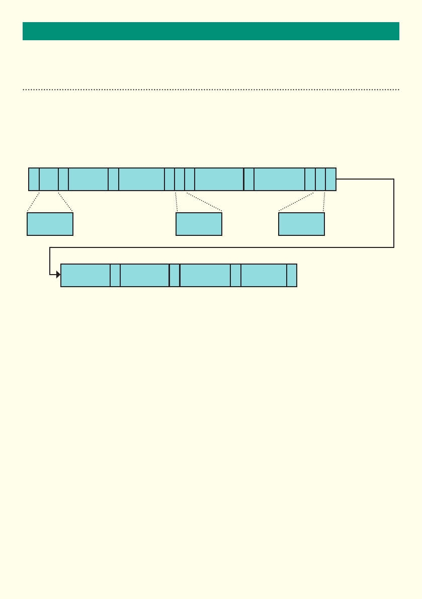
Event Start message
This message is sent after the radar has established that a vehicle has entered the radar’s beam.
The numbers above the boxes in the diagram below indicate how many bytes are used for each field.
Event Start message format
Name Size / Bytes Value Notes
STX 1 2 Start of message byte
MT 2‘ES’ = Event Start Message type
, 1 ‘,’ Comma
Frame Number 8XXXXXXXX Frame number in hexadecimal format
, 1 ‘,’ Comma
Target Number 8XXXXXXXX Target identification number in
hexadecimal format
, 1 ‘,’ Comma
Direction 1‘A’ = Approaching Target
‘R’ = Receding Target
‘X’ = Simulated approaching target
‘Y’ = Simulated receding target
Direction the target is travelling.
, 1 ‘,’ Comma
Speed 5‘DDD.D’ Target speed to one decimal place in
decimal format
, 1 ‘,’
Speed Units 1‘M’=MPH
‘K’=km/hr
The speed units used for the
measurement
, 1 ‘,’ Comma
Target Range 5‘DDD.D’ Target range in metres
* 1 ‘*’ Asterisk
Check Sum 2‘XX’ Check sum in hexadecimal format
ETX 1 3 End of message byte
MT ,
S
T
X, , ,D U, , * E
T
X
Frame
Number Target
Number Speed
Speed Units
Direction
A, R, X or Y
Message Type
ES
Target Range Check Sum
2 11 1 1 11 11 1 1 18 8 5 5 2
18
MESSAGE FORMATS
RADAR EVENT MESSAGES
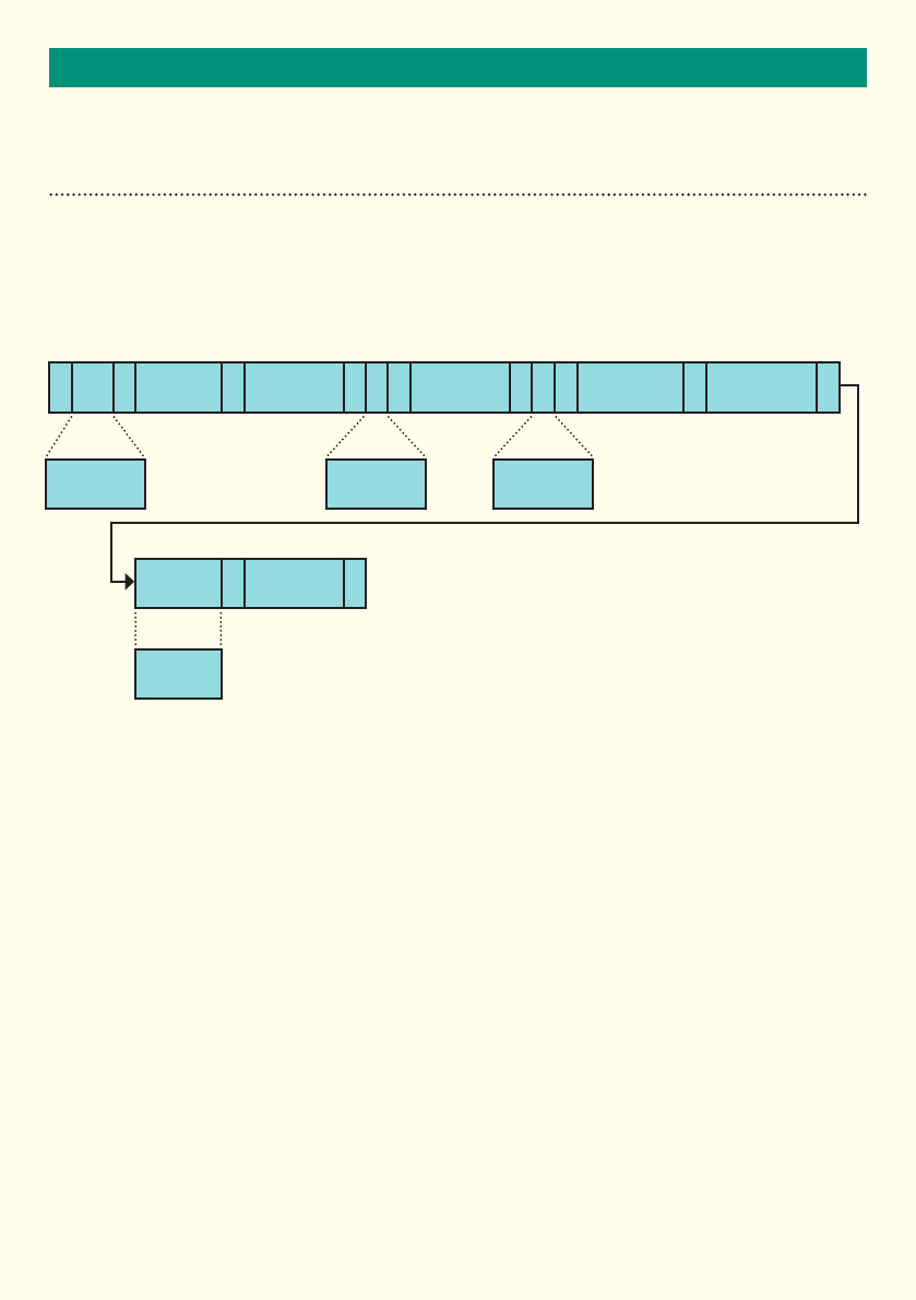
Event End Message
This message is sent once a target has been detected for a significant amount of time. This message can be
used by a host system to trigger a camera to capture images for a receding target enforcement system.
MT ,
S
T
X,
*
,
E
T
X
,D U, , , ,
Frame
Number
MA
Radar
Mounting
Angle
Target
Number
Check Sum
Speed
Speed Units
Direction
A, R, X or Y
Message Type
EE
Target Range Distance Travelled
in Beam
2 11 1 1 11 11 1 1 18 8 5 5 5
1 12 2

19
MESSAGE FORMATS
Name Size / Bytes Value Notes
STX 1 2 Start of message byte
MT 2‘EE’ = Event End Message type
, 1 ‘,’ Comma
Frame Number 8XXXXXXXX Frame number in hexadecimal format
, 1 ‘,’ Comma
Target Number 8XXXXXXXX Target identification number in
hexadecimal format
, 1 ‘,’ Comma
Direction 1‘A’ = Approaching Target
‘R’ = Receding Target
‘X’ = Simulated approaching target
‘Y’ = Simulated receding target
Direction the target is travelling.
, 1 ‘,’ Comma
Speed 5‘DDD.D’ Target speed to one decimal place in
decimal format
, 1 ‘,’
Speed Units 1‘M’=MPH
‘K’=km/hr
The speed units used for the
measurement
, 1 ‘,’ Comma
Target Range 5‘DDD.D’ Target range in metres
, 1 ‘,’ Comma
Distance Travelled
in beam
5‘DDD.D’ The distance a target has travelled
while in the beam of the radar.
, 1 ‘,’
MA 2‘DD’ Radar mounting angle in degrees.
This is the angle the radar uses to
calculate the speed of a target
* 1 ‘*’ Asterisk
Check Sum 2‘XX’ Check sum in hexadecimal format
ETX 1 3 End of message byte
RADAR EVENT MESSAGES
Event End message format
20
MESSAGE FORMATS
RADAR EVENT MESSAGES
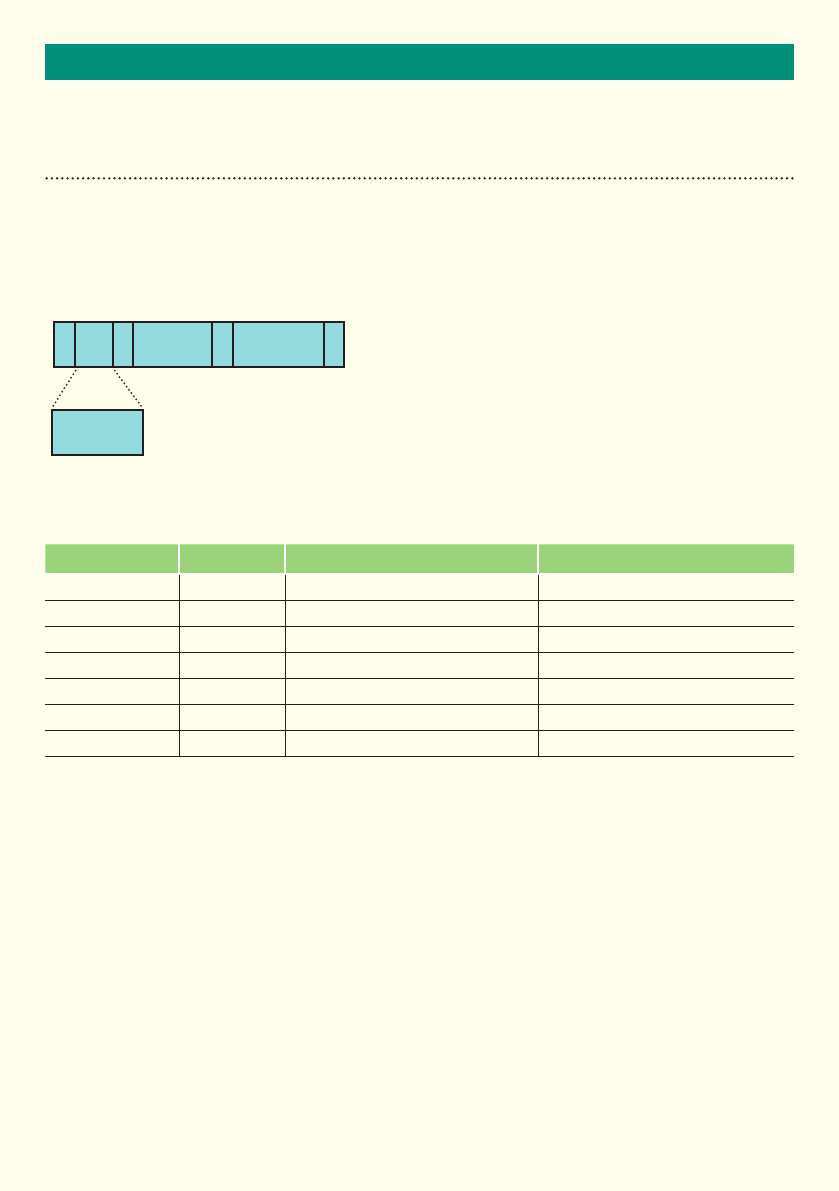
Heart Beat message
This message is sent each time the heart period expires. The heart beat message period is controlled using the
*HBP command. The heart beat period is measured in frames.
Heart Beat message format
Notes to Heart Beat Message
The heartbeat period is set in seconds using the *HBP command. Setting the hearbeat period to 0 secs will turn
the hearbeat off. The maximum setting for the heartbeat period is 86400 secs.
A heartbeat message will always be produced after the radar initialises even if the heartbeat is turned off.
The host system should not send messages to the radar after power-up until this initial heartbeat message is
received.
Name Size / Bytes Value Notes
STX 1 2 Start of message byte
MT 2‘HB’ = Heart Beat Message type
, 1 ‘,’ Comma
Frame Number 8XXXXXXXX Frame number in hexadecimal format
* 1 ‘*’ Asterisk
Check Sum 2‘XX’ Check sum in hexadecimal format
ETX 1 3 End of message byte
MT ,
S
T
X*E
T
X
Frame
Number Check
Sum
2 11 1 18 2
Message Type
HB

21
MESSAGE FORMATS
RADAR EVENT MESSAGES
Tuning Fork message
This message is sent when a tuning fork target has been detected. This message is sent after a event end
message is sent.
Tuning Fork message format
Name Size / Bytes Value Notes
STX 1 2 Start of message byte
MT 2‘TF’ = Tuning Fork Message type
, 1 ‘,’ Comma
Frame Number 8XXXXXXXX Frame number in hexadecimal format
, 1 ‘,’ Comma
Target Number 8XXXXXXXX Target number in hexadecimal format
, 1 ‘,’ Comma
Speed 5‘DDD.D’
, 1 ‘,’ Comma
Speed Units 1‘M’=MPH
‘K’=km/hr
The speed units used for the
measurement
, 1 ‘,’ Comma
Target Range 5‘DDD.D’ Target range in metres
* 1 ‘*’ Asterisk
Check Sum 2‘XX’ Check sum in hexadecimal format
ETX 1 3 End of message byte
MT ,
S
T
X, , , U , * E
T
X
Frame
Number Target
Number Speed
Speed Units
Message Type
TF
Target Range Check Sum
2 11 1 1 11 1 1 18 8 5 5 2
22
MESSAGE FORMATS
RADAR EVENT MESSAGES
Event Quality message
Once an event end message is sent, the measurements relating to the event are analysed. These various
elements of the event are reported in the Event Quality Message.
MT ,
S
T
X, , , ,UD, ,
,,
Frame
Number Target
Number
Speed Units
Direction
A, R, X or Y
Message Type
QM
Peak Power
Speed
Percentage Speed
Readings
Event
Peak Power
Peak Power
Speed Standard
Deviation
Percentage Range
Readings
2 11 1 1 11 11 18 8 5 5 1
*E
T
X
Check Sum
1 13 2
5 1 13

23
MESSAGE FORMATS
RADAR EVENT MESSAGES
Event Quality message format
Name Size / Bytes Value Notes
STX 1 2 Start of message byte
MT 2‘QM’ = Quality Message Message type
, 1 ‘,’ Comma
Frame Number 8XXXXXXXX Frame number in hexadecimal format
, 1 ‘,’ Comma
Target Number 8XXXXXXXX Target number in hexadecimal format
, 1 ‘,’ Comma
Direction 1‘A’ = Approaching Target
‘R’ = Receding Target
‘X’ = Simulated approaching target
‘Y’ = Simulated receding target
Direction the target is travelling.
Peak Power Speed 5‘DDD.D’
, 1 ‘,’ Comma
Peak Power
Speed Standard
Deviation
5‘DDD.D’
, 1 ‘,’ Comma
Speed Units 1‘M’=MPH
‘K’=km/hr
The speed units used for the
measurement
, 1 ‘,’ Comma
Event Peak Power 5‘DDD.D’
, 1 ‘,’ Comma
Percentage
Speed Readings
3‘DDD’ The value of actual speed readings
taken as a function of the total possible
expressed as a percentage
, 1 ‘,’ Comma
Percentage
Range Readings
3‘DDD’ The value of actual range readings
taken as a function of the total possible
expressed as a percentage
* 1 ‘*’ Asterisk
Check Sum 2‘XX’ Check sum in hexadecimal format
ETX 1 3 End of message byte

24
MESSAGE FORMATS
RADAR MESSAGES IN NORMAL OPERATION
Example data from radar set in Bi-Directional Mode and the Heartbeat set to 5 seconds.
HB,00003560*68
HB,00003930*40
ES,00003B15,00000014,R,029.3,M,017.1*2A
EE,00003B87,00000014,R,029.5,M,023.2,009.5,022.0*DE
QM,00003B87,00000014,R,029.5,00.93,M,095.1,081,081*84
HB,00003D00*31
HB,000040D0*BE
HB,000044A0*26
HB,00004870*D4
ES,00004988,00000015,R,029.1,M,017.4*46
EE,00004A0A,00000015,R,029.7,M,022.2,010.7,022.0*78
QM,00004A0A,00000015,R,029.7,00.67,M,092.8,087,083*7E
ES,00004AE6,00000016,R,031.0,M,018.1*20
EE,00004B4D,00000016,R,031.5,M,021.7,009.5,022.0*9C
QM,00004B4D,00000016,R,031.5,00.52,M,093.4,086,085*E2
ES,00004B55,00000017,A,030.1,M,030.5*F4
EE,00004BAA,00000017,A,029.2,M,029.0,006.8,022.0*86
QM,00004BAA,00000017,A,029.2,00.82,M,080.3,070,065*9C
HB,00004C40*D1
ES,00004D86,00000018,A,033.1,M,030.2*CE
EE,00004DCE,00000018,A,032.9,M,027.9,006.7,022.0*7C
QM,00004DCE,00000018,A,032.9,00.63,M,084.4,073,071*75
ES,00004F7D,00000019,A,040.1,M,032.2*9D
EE,00004FC9,00000019,A,039.7,M,030.2,007.8,022.0*6A
QM,00004FC9,00000019,A,039.7,00.64,M,085.9,085,081*25
HB,00005010*7B
HB,000053E0*8D

25
MESSAGE FORMATS
EXPLANATORY NOTES FOR RADAR EVENT & QUALITY MESSAGES
TheEventStart(ES)messagecontainsbothinitialtargetspeedandrangeinformation.Theradarwillhave
tracked the vehicle for a short distance before this message is sent. As only a relatively small amount of target
information is available to the radar at this stage, the range and speed of the target are not fully evaluated by
the radar and are provided for the system to make some initial decisions about whether to be interested in the
target. The initial speed and range readings in the ES message will have been qualified by the radar against a
series of checks to ensure that the event information is of sufficient quality to proceed with a target track. The
physical position on the road of the target corresponding to the sending of the ES message can be moved by
alteringtheEventStartDistance(*ESD).AlongerESDwillimprovethequalityoftheESspeedanddistance
measurement and make the ES message occur later. Reducing the ESD will have the opposite effect. Making
the ESD too small may lead to premature ES messages.
WhenthevehiclecannolongerbetrackedbytheradaranEventEnd(EE)messageisgenerated.Thismessage
contains the speed of the vehicle which should be used for the Event as all possible speeds would have been
processed during the event. The range of the target in the EE message will generally be different from that of
the ES message because the target will have moved along the carriageway during the event. Generally, the ES
range will be less than the EE range for receding target and vice versa. The distance the target travels after the
trackislosttowhentheEEmessageissentissetbytheEventEndDistance(*EED)message.MakingtheEED
too small may result in multiple events being generated for a single target.
IntheEventEndmessage,thedistancetravelledinthebeambythetarget(EventLength)isreportedinmetres.
This measurement is directly proportional to the length of the target in the event. Depending on the range this
measurement will be approximately 8m for a saloon car and approximately 20m for a truck. Generally, a larger
event length can result in a larger difference in the range measurements reported in the ES and EE messages.
TheQualityMessage(QM)alwaysimmediatelyfollowstheEEmessage.ThereportedPeakPowerSpeedin
the QM is the same as that used in EE speed reading. The radar processes 195 readings per second and the
standard deviation of all those readings for the associated event are reported as a standard deviation in the QM.
The peak power reading is the maximum signal strength seen for the event. The peak power for a given target
will be reduced at increasing range. Generally, for a given range, cars produce a lower peak power reading than
for trucks.
Whilst the radar processes 195 range and speed readings per second not all these readings pass the radars
qualitycheckforagivenreading.Say,100speedreadingsarecollectedforanevent(that’saneventwhichlasts
approx.513mS)buttheradarrejects12ofthereadings,theQMeldPercentageSpeedReadingswillreport
088. That is, 88 good readings from the possible 100 taken is reported as 88%.
Firstly, the speed reading is assessed and then the corresponding range reading for that speed is then assessed.
If a speed reading is rejected, the corresponding range reading is automatically rejected. Continuing with the
example, there will be 88 ranges corresponding to the accepted speeds. Each range is then quality checked to a
given tolerance and rejected or passed. If they all pass the range quality check the Percentage Range Readings
will report 088. The Percentage Range Readings field is always less than or equal to the Percentage Speed
Readings. Finally, if the radar had rejected 14 of the available range measurements the reported Percentage
Range Reading would be 074.

26
MESSAGE FORMATS
RADAR ERROR MESSAGES
Operational Error message
The operational error message is an unsolicited message used to report degrees of variance of the radar from
normal operation.
Operational Error message format
Name Size / Bytes Value Notes
STX 1 2 Start of message byte
MT 2‘ER’ = Error Message Message type
, 1 ‘,’ Comma
Error Number 2DD Error number in decimal format - see
table on next page for details
, 1 ‘,’ Comma
Reference
Number
5DDDDD Reference number used to help
isolate error source. This can change
between software versions and should
not be used by the host system.
,1‘*’ Asterisk
Check Sum 2‘XX’ Check sum in hexadecimal format
ETX 1 3 End of message byte
MT ,
S
T
X, * E
T
X
Error Number Reference
Number Check
Sum
2 11 1 12 5
Message Type
ER
2 1

27
MESSAGE FORMATS
RADAR ERROR MESSAGES
Error Number table
Error Number Description Response Actions
01 Corruption of User
Configuration Data
Radar will attempt to
restore Factory Default
Data configuration set
User will need to reset individual
configuration variances from default set
02 Corruption of
Factory Default Data
Configuration set
Radar operation will
automatically shut down as
operation to specification
cannot be assured
Return radar to AGD for repair and/or
recalibration
03 Corruption
of Critical
Configuration Data
Radar operation will
automatically shut
down as operation to
specification is not
possible
Return radar to AGD for repair and/or
recalibration
04 Internal
communication
error.
Communication
between radar
processors has
failed.
Radar operation will
automatically shut down
Return radar to AGD for repair and/or
calibration
05 General error Radar has internal code
tags to indicate resource
usage and levels of
processing load
User should ignore if infrequent.
Repeated occurrence suggests radar
nearing specification limits and should be
shut down by the user. It should be noted
that repeated occurrence of this message
may be owing to the specific site at which
it is deployed and or the associated
targets making the radar work close to its
operational processing limits.
06 Sampling
Frequency Error
The radar will continue to
operate.
If the sampling Frequency Error is
persistent ie more than one message
every 10 secs, then the radar operation
to specification cannot be assured and
should be shut down by the host system.
The radar should be returned to AGD for
repair and/or recalibration

28
CRC8 C CODE WORKED EXAMPLE
CRC8 C CODE
CRC8 checksums are used on the standard radar messages. The checksum calculation is performed on all
bytes, up to and including the asterisk character. These checksums are calculated using the following C code.
//Lookup table for CRC8 calculation
//Needs to be initialised with InitCRC8
U8 crc8_table[256];
/********************************MemCRC8*******************************
This function calculates the CRC8 of a data array pointed to by data
and of length length.
Usespolynomialx^8+x^2+x+1.Lookuptableusedbyfunctionisinitialised
by the InitCRC8 function.
*/
unsignedcharMemCRC8(void*data,unsignedintlength)
{
unsigned char crc8;
unsigned char i;
unsigned char *dptr;
dptr=(unsignedchar*)data;
crc8 = 0; //Start with a value of 0
for(i=0;i<length;i++)
{
crc8 = crc8_table[crc8 ^ *dptr];
++dptr;
}
return crc8;
}
#deneGP0x107/*x^8+x^2+x+1*/
#define DI 0x07
/****************************InitCRC8******************************
Initialises the lookup table for the MemCRC8 function
Usespolynomialx^8+x^2+x+1
*/
voidInitCRC8(void)
{
int i,j;
unsigned char crc;
for(i=0;i<256;i++)
{
crc = i;
for(j=0;j<8;j++)
{
crc=(crc<<1)^((crc&0x80)?DI:0);
}
crc8_table[i] = crc & 0xFF;
}
}
29
ANTENNA PLOTS
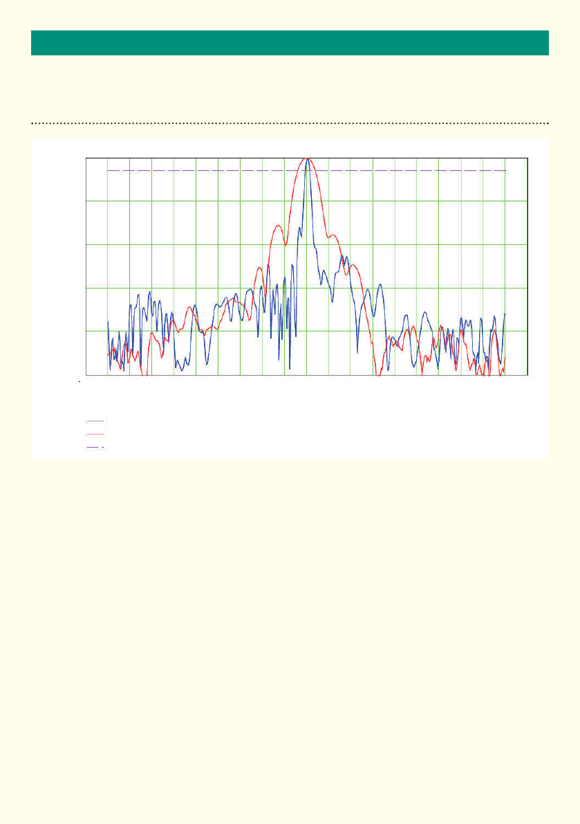
ANTENNA PLOTS
Horizontal Beam Pattern
Vertical Beam Pattern
3dB Level
Angle(Degrees)
Power(dB)
-200 -180 -160 -140 -120 -100 -80 -60 -40 -20 0 20 40 60 80 100 120 140 160 180 200
0
-10
-20
-30
-40
-50

30
TECHNICAL SPECIFICATIONS
speCifiCations
Technology FMCW Radar
Radiated Power <100mW EIRP
Transmit Frequency In the band 24.075 to 24.125GHz
Transmit Bandwidth 9.4MHz
Range 2 to 60m
Mounting Flange fixings or tripod mount
Mounting Height 1 - 3.5m nominal
Speed Range 20 to 320kph
Weight 0.8 Kg nominal
Housing Material Polycarbonate(UL94V-2)
Housing Finish Self coated black
Sealing IP66
Operating Temperature -20°Cto+60°C
Power 2.9 - 3.3W
Power Supply 10-16Vdc
Radar Output RS422
EMC Specification ETSI EN 301 489 and BS EN 50293
Radio Specification ETSI 300.440, FCC CFR47 Part 15.245
Owing to the Company’s policy of continuous improvement, AGD Systems Limited reserves the right to change their specification or design
without notice.
This device complies with part 15 of the FCC Rules. Operation is subject to the following two conditions:
(1)Thisdevicemaynotcauseharmfulinterference,and
(2)thisdevicemustacceptanyinterferencereceived,includinginterference,thatmaycauseundesiredoperation.
See 47 CFR Sec. 15. 19
A separation distance of at least 20 centimetres should normally be maintained between this product and the body of users or nearby
persons.
Changes or modifications to this equipment, not expressly approved by AGD Systems Ltd, may void the user’s authority to operate this
equipment.
112mm
50mm
50mm
288mm

31
TEST & CALIBRATION
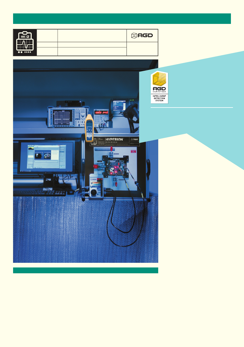
DEDICATED TEST EQUIPMENT
The key test functions performed by Hyperion to Certify the premium
performance of the 342 are:
• Truerangesimulationoftarget
• Targetspeedanddirectionsimulationatagivenrange
• Radartargetprocessingoptimisation
• Transmittedradarfrequencymodulationmeasurement
• Vericationofinterfaceandcommunicationprotocols
• Testcycletimeof9minutes
LIFETIME PRODUCT TRACEABILITY
There are clearly defined pass and fail criteria at all stages within the Hyperion test
process. The test results in association with the product build revision are recorded
on a product serial number basis. The full suite of test measurements is instantly
sent to the dedicated product database within the AGD secure server facility,
providing full traceability during the product lifetime.
The AGD Certified symbol is your mark of assured performance.
TEST
EQUIPMENT:
TEST FUNCTION:
PRODUCT TEST:
HYPERION was designed and developed
by AGD Systems
HYPERION
I
NTE
L
L
I
G
ENT
D
ETECT
I
O
N SYSTE
M
S
315
|
316
|
317
|
335
|
336
|
342
•
True range simulation of target
•
Test cycle time 9 minutes
•
Radar target processing optimisation
•
Verification of communication protocols
TM
FULL
RANGE
HYPERION is dedicated to the testing of the
AGD portfolio of ‘ranging’ FMCW vehicle radars.
It provides true range simulation and both target
speed and direction simulation at a
given range
Hyperion™ is a bespoke set of test
equipment designed and developed
by AGD Systems. It is dedicated to the
testing of the AGD portfolio of ‘ranging’
FMCW vehicle radars. 100% of the 342
units manufactured at AGD are
Certified by Hyperion.
The key test
functions performed
by Hyperion to Certify the
premium performance of your
Intelligent Detection System are:
• Truerangesimulationoftarget
• Targetspeedanddirectionsimulation
at a given range
• Radartargetprocessingoptimisation
• Transmittedradarfrequency
modulation measurement
• Verificationofinterfaceand
communication protocols
• Testcycletimeof9minutes
The radar test sequences performed
by Hyperion on the radar under test
provides a thorough examination of
the performance of the 342 radar and
specifically the ranging measurement
capability provided by the FMCW
technology deployed. This gives full
control of simulated targets’ signal
size, speed, direction and range.
Optimisation of frequency signals on
Hyperion ensures full compatibility with
country requirements within the 24GHz
radar operating band.
MANUFACTURING TEST PROCESS
32
3333
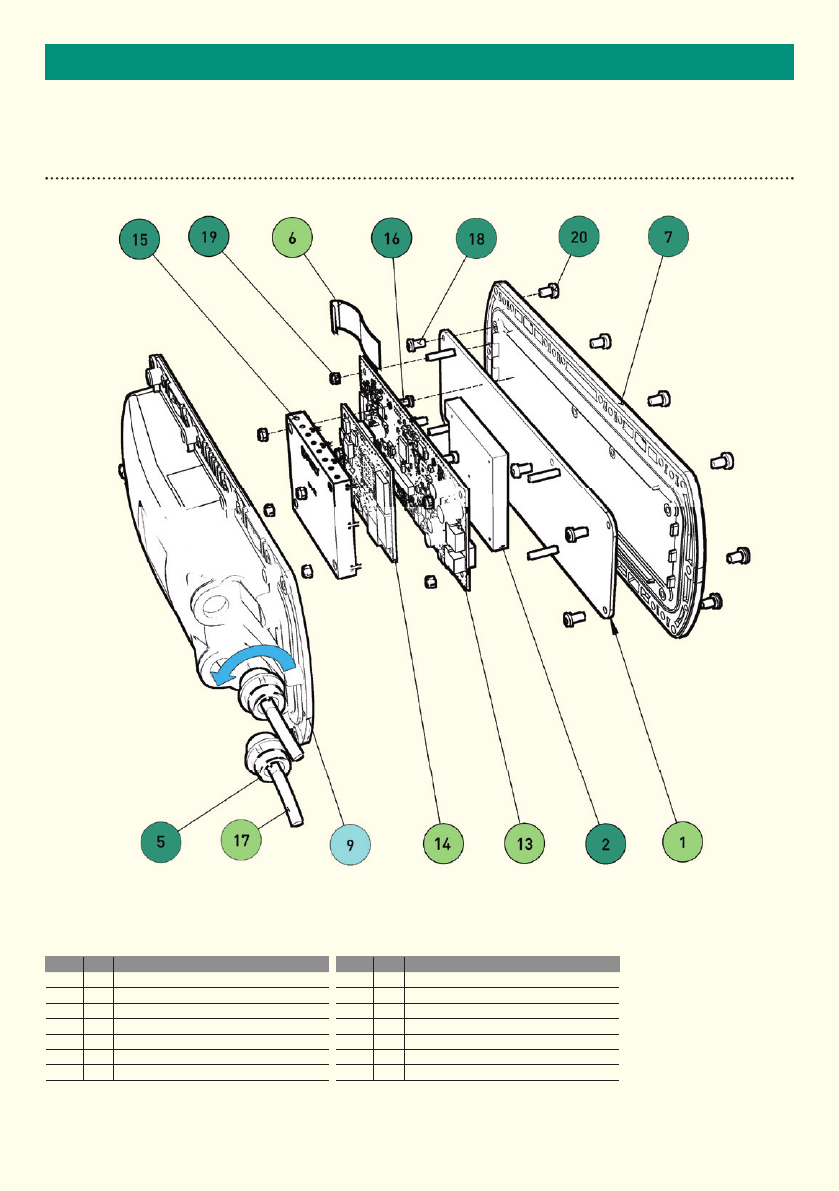
IMPORTANTEND OF LIFE – DISPOSAL INSTRUCTIONS (EOL)
Item Qty Material
1 1 PCB Assembly
2 1 Zinc Alloy
5 2 ABS
6 1 Mixed Metal & PVC
7 1 Polycarbonate
9 1 PC, Brass
13 1PCB Assembly
Item Qty Material
14 1PCB Assembly
15 1Nickel Silver
16 4Steel
17 2Mixed Metal & PVC
18 6Steel
19 8Steel
20 10 Steel
• Reuse / Recycle
• Separate & Recycle
• Downcycle
• Hazardous Recovery
• Non- Recyclable
This document serves as a guideline only for EOL procedures and further guidance may need to be sought from the appropriate authority or agency.
AGD342 RADAR TRAFFIC DETECTOR

34
IMPORTANT
SAFETY PRECAUTIONS
All work must be performed in accordance with company working practices, in-line with adequate risk
assessments. Only skilled and instructed persons should carry out work with the product. Experience and safety
procedures in the following areas may be relevant:
• Workingwithmainspower
• Workingwithmodernelectronic/electricalequipment
• Workingatheight
• Workingattheroadsideorhighways
1. ThisproductiscomplianttotheRestrictionofHazardousSubstances(RoHS-EuropeanUniondirective
2002/95/EG).
2. Should the product feature user-accessible switches, an access port will be provided. Only the specified
access port should be used to access switches. Only non-conductive tools are to be used when operating
switches.
3. The product must be correctly connected to the specified power supply. All connections must be made
whilst the power supply is off or suitably isolated. Safety must take always take precedence and power
must only be applied when deemed safe to do so.
4. No user-maintainable parts are contained within the product. Removing or opening the outer casing is
deemed dangerous and will void all warranties.
5. Under no circumstances should a product suspected of damage be powered on. Internal damage may be
suggested by unusual behaviour, an unusual odour or damage to the outer casing. Please contact AGD
for further advice.
!

35
IMPORTANT
IMPORTANT INFORMATION
Low Power Non-Ionising Radio Transmission and Safety
Concern has been expressed in some quarters that low power radio frequency transmission may constitute
a health hazard. The transmission characteristics of low power radio devices is a highly regulated environment
for the assurance of safe use.
There are strict limits on continuous emission power levels and these are reflected in the testing specifications
that the products are approved to. These type approval limits are reflected in the product specifications required
foratypicalgeographicareasuchasthosefortheEU(ETS300:440),fortheUSA(FCCpart15c)andforAustralia/
NewZealand(AS/NZS4268).Thelimitsadoptedinthesespecicationsaretypicallyreplicatedinmanyother
localized specifications.
The level of safe human exposure to radio transmission is given by the generally accepted guidelines issued by
theInternationalCommissiononNon-IonizingRadiationProtection(ICNIRP).Thisbodyhasissuedguidance
forlimitingexposuretotime-varyingelectric,magneticandelectromagneticelds(upto300GHz)whichare
quoted below.
Note 1 Values are calculated conversions for comparison purposes.
Note 2 Other equivalent limits include; Medical Research Council Limit of 10mW/cm2, IACP limit of 5mW/cm2 (at 5cm) and
UK CAST limit of 5mW/cm2
Note 3 Calculation is made on the assumption antenna is a point source therefore the actual value is likely to be significantly
less than that quoted. Note that a theoretical max level at a 5cm distance (which gives 0.318mW/cm2) is at a point in
the field where the radar beam is not properly formed.
Note 4 Comparison for product model 342 operating in the band typically 24.050GHz to 24.250GHz
From the table it can be seen that it is extremely unlikely that a potentially hazardous situation could occur owing
to the use of such low power devices.
It is considered to be good practice not to subject humans to radiation levels higher than is necessary. In a works
environment where multiple equipment on soak test are to be encountered then it is considered good practice to
contain the equipment in an appropriate enclosure lined with radar absorbing material.
Radar and ICNIRP limit comparison Typical Informative Limits for Radar
Transmission Approval
Radar
Transmitted
Level(Note4)
ICNIRP Limit
(Table6)
Exposure
Margin
ETS300:440
FCC(part15c)
AS/NZS 4268
Power
(mWEIRP)
<100mW
(<20dBm)
N/A N/A 100mW
(20dBm)
1875mW
(Note1)
100mW
(20dBm)
Max Power
Density
(mW/cm2)
3.18µW/cm2
at 50cm
(Note3)
<50W/m2
(5mW/cm2)
(Note2)
0.064%
N/A
N/A
N/A
Field Strength
(V/m)at3m
<0.58V/m
(5.8mV/cm)
(Note1)
<137V/m
(1370mV/cm)
0.42%
0.58V/m
(5.8mV/cm)
(Note1)
2500mV/m
(25mV/cm)
0.58V/m
(5.8mV/cm)
(Note1)

DISCLAIMER
Whilewe(AGDSystems)endeavourtokeeptheinformationinthismanualcorrectatthetimeofprint,wemakeno
representations or warranties of any kind, express or implied, about the completeness, accuracy, reliability, suitability
or availability with respect to the information, products, services, or related graphics contained herein for any purpose.
Any reliance you place on such information is therefore strictly at your own risk. In no event will we be liable for any loss
or damage including without limitation, indirect or consequential loss or damage, or any loss or damage whatsoever
arising from loss of data or profits arising out of, or in connection with, the use of this manual.
WARRANTY
All 342 radars are supplied with a 12 month return to factory warranty. Products falling outside this period may
be returned to AGD Systems for evaluation, chargeable repair or re-calibration.
AGD Systems Limited
White Lion House T: +44(0)1452854212
Gloucester Road, F: +44(0)1452854213
Staverton, Cheltenham E: sales@agd-systems.com
Gloucestershire, GL51 0TF, UK W: agd-systems.com
ISO 14001
Registered
Environmental
Management015
ISO 9001
Registered
Quality
Management015
©AGD Systems Limited 2013 Doc. Ref. 342 PM ISS8