AGD SYSTEMS 350101 350 Traffic Management Radar User Manual
AGD SYSTEMS LTD 350 Traffic Management Radar Users Manual
Users Manual
ISO 14001
Registered
Environmental
Management015
ISO 9001
Registered
Quality
Management015
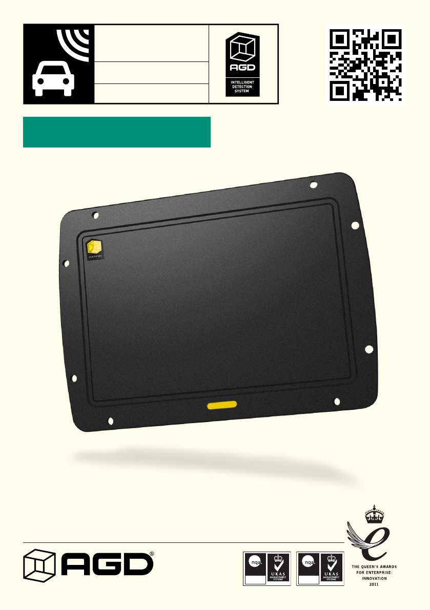
VEHICLE DETECTION
Enforcement Radar Traffic Detector
350
CERTIFIED
PRODUCT MANUAL
©AGD Systems Limited 2015 Doc. Ref. 350 PM ISS 2

2
INTRODUCTION
Product & technology 3
Key features 3
Typical applications 4
Product overview 5
INSTALLATION
Radar mounting 6
Radar Installation - Red Light Enforcement (receding flow) 7-8
Radar Installation - Red Light Enforcement (avancing flow) 9-10
Radar mounting 11
Selecting a suitable site 11
Radar Speed Accuracy 11
Radar Range Accuracy 11
Radar Angular Accuracy 11
Radar Angle and Range Modes 11
SYSTEM HARDWARE OVERVIEW
System hardware overview 12
RS422 serial interface 13
Ethernet Interface 14
Power supply 15
Power up Sequence 15
Power Supply Tolerance 15
Mating Connector Pin Out Connections 15
RADAR CHARACTERISTICS
General 16
Frequency Variants 17
Antenna Plots 18
RADAR COMMANDS
Radar Command Overview 19
Radar Command list 20-21
MESSAGE FORMATS
Detect Message 22-23
Event Trigger Point Message 24-25
Tracked Target Message 26-27
Heartbeat Message 28
TECHNICAL SPECIFICATIONS
Product specification 29
MANUFACTURING TEST PROCESS
Hyperion Test Equipment 30
END OF LIFE – DISPOSAL INSTRUCTIONS (EOL) 31
IMPORTANT SAFETY INFORMATION
Safety precautions 32
Low power non-ionising radio transmission and safety 33
DISCLAIMER 36
Warranty 36
TABLE OF CONTENTS
3
INTRODUCTION
PRODUCT & TECHNOLOGY
KEY FEATURES
• Radar reports speed, range and positional data to each event
• Tracks up to 32 simultaneous targets
• Speed measurement from 10kph - 250kph
• Target range 4m - 85m
• 40º field of view
• Suitable for advancing or receding traffic flow
• Dual user selectable virtual trigger points
• High speed RS422 serial communications
• Optional Ethernet interface
• Continuous radar self-check features
• Self calibrating bandwidth control
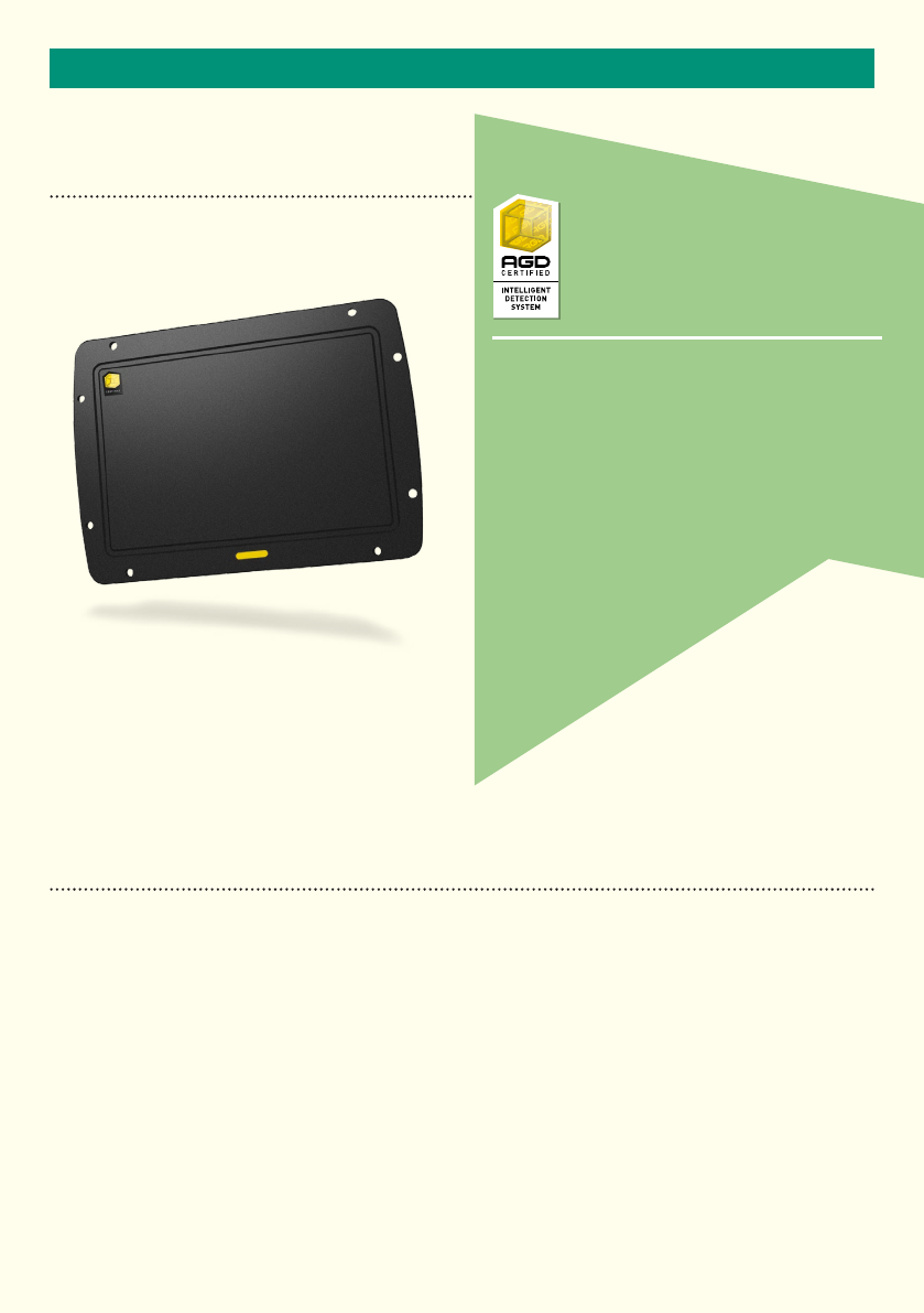
350
The 350 is specifically designed for O.E.M integration
into photo enforcement systems to measure the
position, speed and range of passing vehicles.
Operating in the K-band at 24GHz, the radar offers
market leading performance for demanding
applications such as red light (&speed) and yellow box
violations at signalised intersections.
Positioned in front of (or optionally behind) an
intersection stop line, the 350 will track up to
thirty two targets simultaneously and allows
the setting of two precise trigger
points for data output to the
host system when a
violation occurs.
4
INTRODUCTION
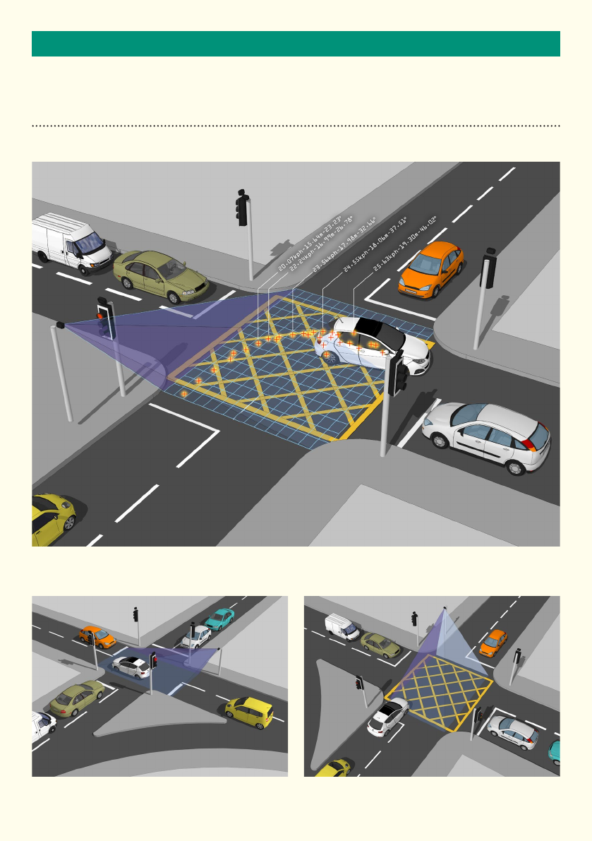
TYPICAL APPLICATIONS
Vehicle speed, distance and angle is captured through the detected zone
Red light violation Yellow box violation
5
INTRODUCTION
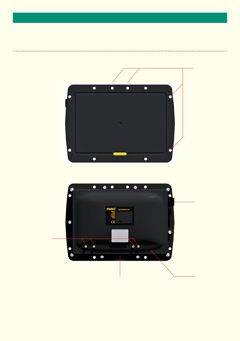
PRODUCT OVERVIEW
Tripod mounting point
or
mounting bracket fixing
Flange mounting
points
Multi-function LEDs
Multi-pin
mating
connector
RJ45 Ethernet
connector
6
INSTALLATION
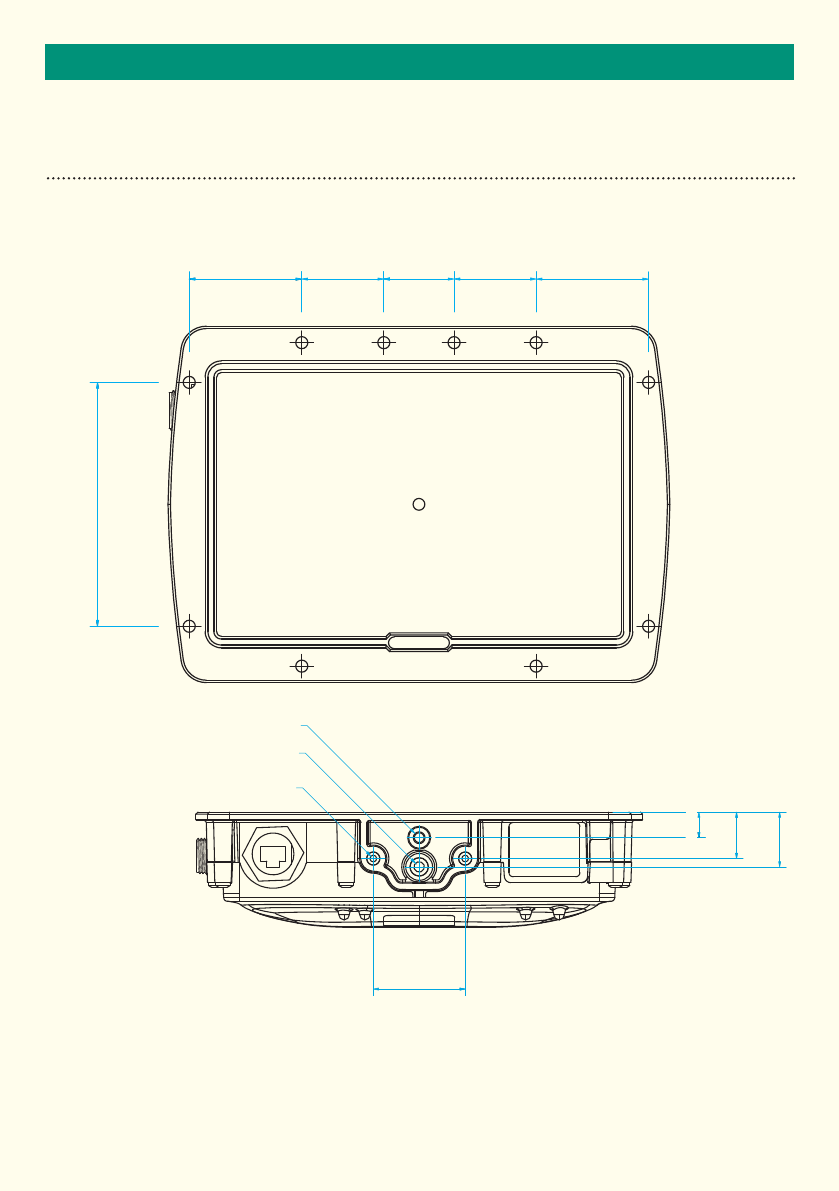
RADAR MOUNTING
The radar mounting features and dimensions are shown below.
30,0035,00 35,00 48,0048,00
104,00
12,25
22,25
26,25
44
M4x0.7 - 6H
1/4-20 UNC - 1B
Ø5,70 -14,97 DEEP
7
INSTALLATION
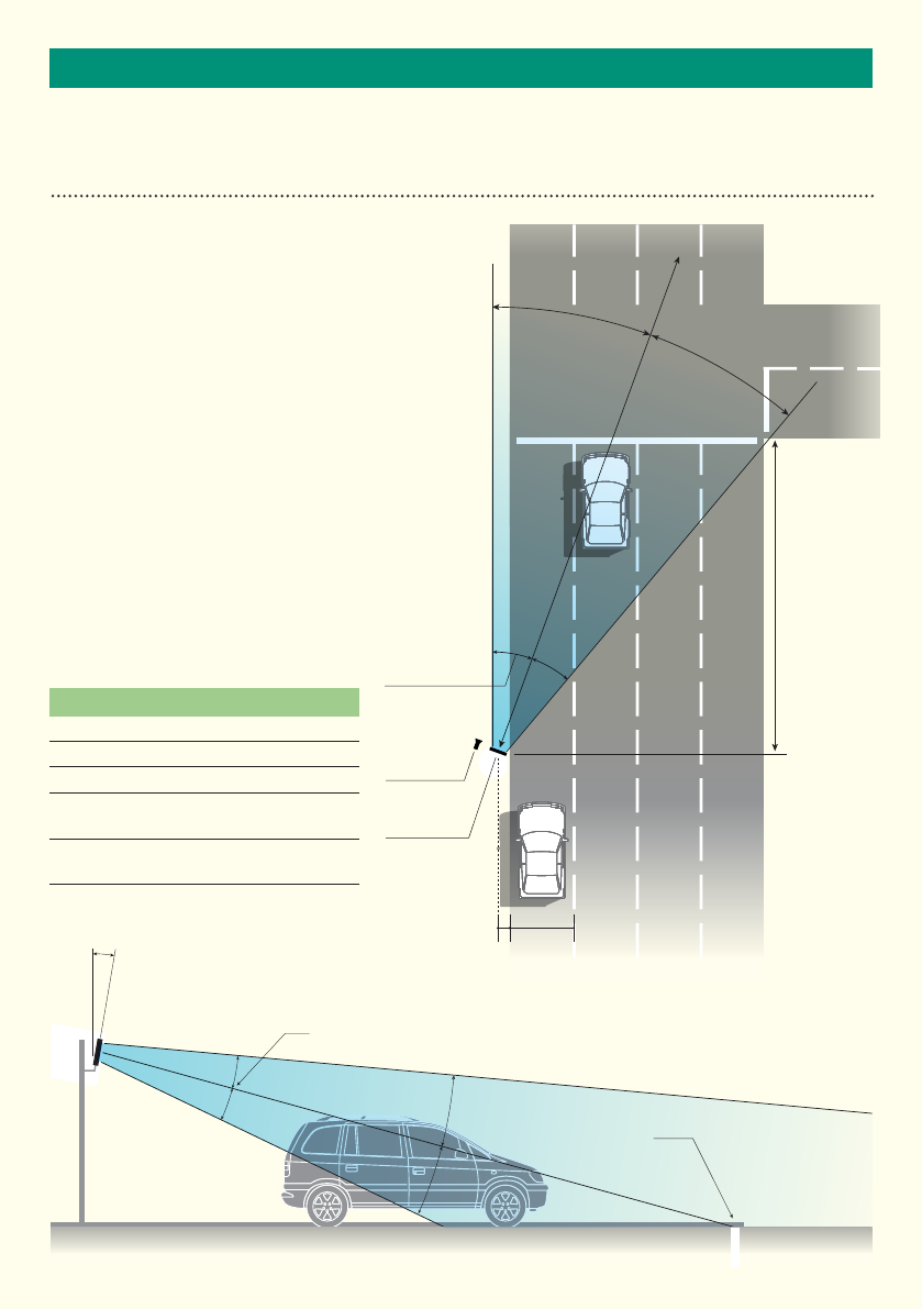
RADAR INSTALLATION - RED LIGHT ENFORCEMENT (RECEDING FLOW)
The nature of the design of the radar lends itself to
versatility in its mounting on the roadway. There are
however, factors to be considered when siting the
radar to ensure optimum performance is achieved.
The radar should be installed at an angle of
approximately 20º from the pavement line and sited
toward the centre of the junction area. The area to
be enforced should be within the ‘D1’ range of the
radar (85 metres max). Mounting height should
be approximately 3 metres from ground level.
Offset (setback) should be approximately 2 metres.
Declination angle of the radar head should be
approximately 10º.
Care should be taken to ensure that the area of
interest is covered by the 40º field of view, this can
be affected by mounting height, correct mounting
angle to the road, correct declination
angle and the radar offset.
Lane 1
3.5m
D2
D1
Offset 2m
Horizontal
field of view
Host
Enforcement
350 Radar
Lane 2 Lane 3 Lane 4
Vertical field of view
Approximate
stopline location
Declination angle
(Downward toward
pavement)
20º
10º
20º
350 Radar Installation Approximation
D1 - Maximum range at centre of radar bore (85m)
D2 - approximate distance from the stopline (20m)
Offset - approximate setback from lane 1 (2m)
Horizontal field of view - approximately ±20º from
centre bore of radar
Vertical field of view - approximately ±10º from centre
bore of radar

8
INSTALLATION
RADAR INSTALLATION - RED LIGHT ENFORCEMENT (RECEDING FLOW)
This diagram shows the potential beam coverage of the
350 Radar being used to monitor an intersection for red
light enforcement. The ‘D4’ distance is an important
consideration when adjusting mounting parameters of
the radar.
Adjusting mounting height, offset and mounting angle
will all have the effect of increasing or decreasing the
‘D4’ value. The value is defined as the initial point of
radar coverage on the surface of the roadway. See
diagram below.
20º
20º
Lane 1
3.5m
D4
350 Radar
Lane 2 Lane 3 Lane 4
350 Radar Installation Analysis (beam coverage)
D4 - This distance is approximately four metres based on suggested
parameters but is variable.
Initial point of radar coverage
on road shifts upon adjustment
of radar height.
Shift
9
INSTALLATION
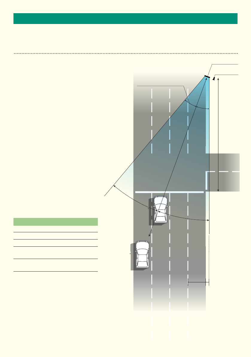
RADAR INSTALLATION - RED LIGHT ENFORCEMENT (ADVANCING FLOW)
The nature of the design of the radar
lends itself to versatility in its mounting
on the roadway. There are however,
factors to be considered when siting the
radar to ensure optimum performance is
achieved.
The radar should be installed at an angle
of approximately 20º from the pavement
line and sited toward the centre of the
junction area. The area to be enforced
should be within the ‘D1’ range of the
radar (85 metres max). Mounting height
should be approximately 3 metres from
ground level. Offset (setback) should
be approximately 2 metres. Declination
angle of the radar head should be
approximately 10º.
Care should be taken to ensure that the
area of interest is covered by the 40º field
of view, this can be affected by mounting
height, correct mounting angle to the
road, correct declination
angle and the radar offset.
Lane 1
3.5m
D2
D1
Offset 2m
Horizontal
field of view
350 Radar
Host
Enforcement
Lane 2 Lane 3 Lane 4
20º
20º
350 Radar Installation Approximation
D1 - Maximum range at centre of radar bore (85m)
D2 - approximate distance from the stopline (20m)
Offset - approximate setback from lane 1 (2m)
Horizontal field of view - approximately ±20º from
centre bore of radar
Vertical field of view - approximately ±10º from centre
bore of radar
10
INSTALLATION
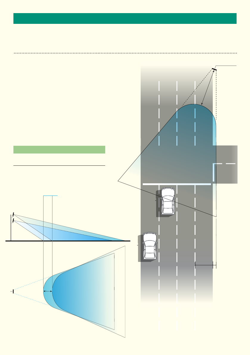
RADAR INSTALLATION - RED LIGHT ENFORCEMENT (ADVANCING FLOW)
This diagram shows the potential beam
coverage of the 350 Radar being used
to monitor an intersection for red light
enforcement. The ‘D4’ distance is an
important consideration when adjusting
mounting parameters of the radar.
Adjusting mounting height, offset and
mounting angle will all have the effect of
increasing or decreasing the ‘D4’ value. The
value is defined as the initial point of radar
coverage on the surface of the roadway. See
diagram below.
Lane 1
D4
Lane 2 Lane 3 Lane 4
350 Radar Installation Analysis (beam
coverage)
D4 - This distance is approximately four metres based on
suggested parameters but is variable.
Initial point of radar coverage
on road shifts upon adjustment
of radar height.
350 Radar
3.5m
Offset 2m
Shift

11
INSTALLATION
RADAR MOUNTING
As highlighted on the previous page(s). There is a certain amount of flexibility in the position of where the
RADAR is mounted. The offset, height, distance from stop line, even orientation in relation to the stop line can
be altered, however when selecting a mounting position, all parameters should be reviewed to ensure that
sufficient RADAR beam coverage of the area of interest, can be achieved at the chosen mounting location.
Selecting a Suitable Site
When choosing to deploy the radar at a location, the following is a non-exhaustive list of considerations which
should be taken into account.
• Does the proposed mounting position give sufficient beam coverage to ‘view’ the enforceable area ?
• Are there any large reflecting surfaces directly in front or behind the RADAR mounting position ?
Radar Speed Accuracy
Simulated target up to 262km/hr ±…….Km/hr
Real target typical accuracy ±…….Km/hr
Radar speed resolution readout 0.1 Km/hr
Radar Range Accuracy
Simulated range up to 70m ±………m
Real target range accuracy ±2m for a range up to 70m
Range readout resolution 0.1m
Radar Angular Accuracy
Simulated angle ±…….º
Real target angular accuracy ±…….º
Angular readout resolution 0.1 º
Radar Angle and Range Modes
The radar has two modes when reporting range and angle. This can be set to a distance based range and
angular approach of the target vehicle, or alternatively, the position of the vehicle can be expressed as an
‘X, Y’ co-ordinate (polar or cartesian).
12
SYSTEM HARDWARE OVERVIEW
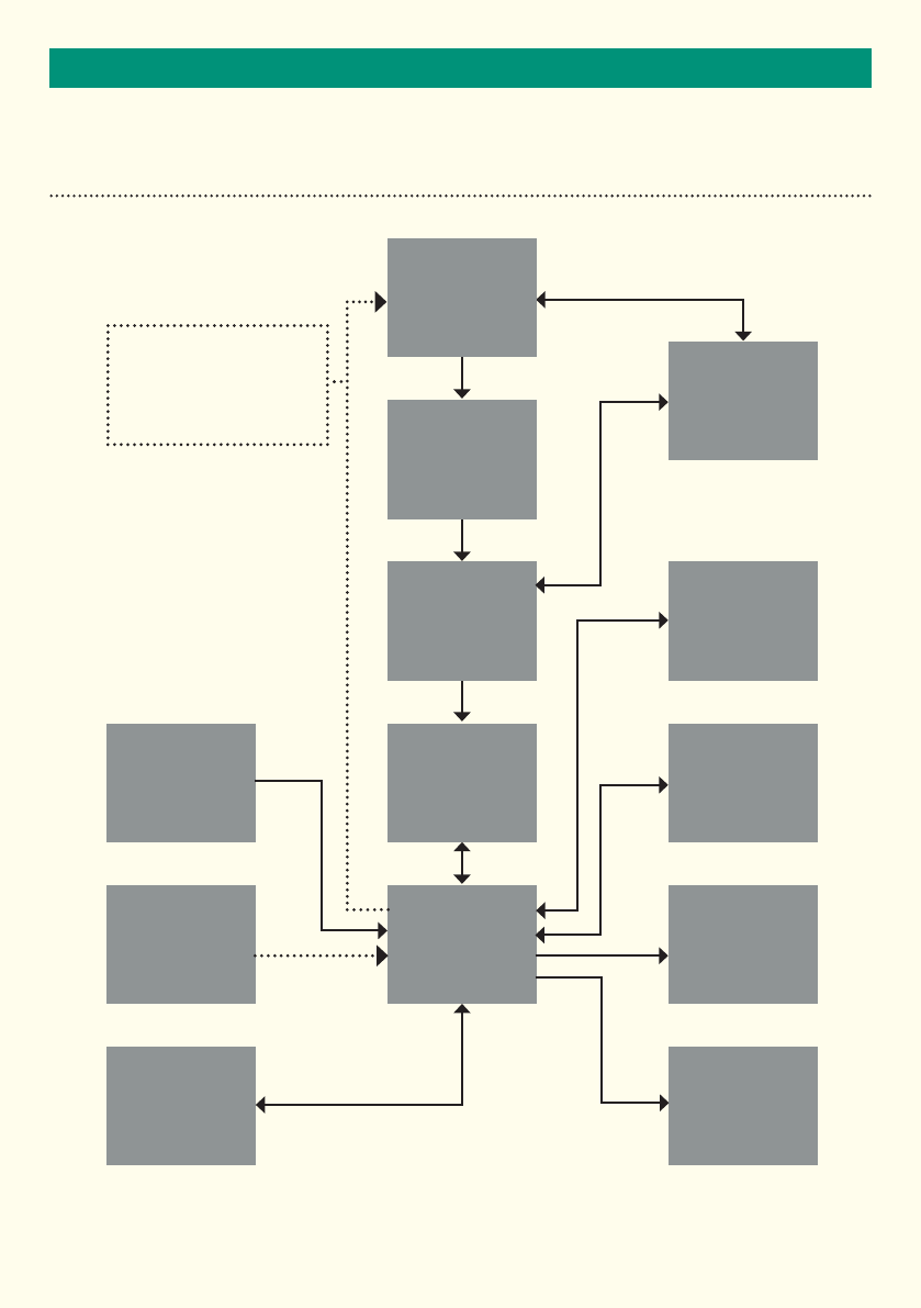
SYSTEM HARDWARE OVERVIEW
Transmitter
Modulation
Control
Target Simulator
Amplifiers
& Signal
Conditioning
Power &
Modulation
Control
Analogue
to Digital
Converter RS422
Field
Programmable
Gate Array Ethernet*
Temperature
Sensor
Digital Signal
Processor &
Co-Processor Opto / RelayLogical Input
Bluetooth /
WiFi*
Non-Volatile
Memory
*Note: not all functions currently active

13
SYSTEM HARDWARE OVERVIEW
RS422 SERIAL INTERFACE
A UART interface is provided that uses RS422 voltage levels on the multi-pin mating connector.
The default baud rate for this interface is 921600.
The serial interface default set-up, during normal operation is shown in the table below.
The RS422 provides the primary output of the radar in the form of ASCII messages
Interface connector details are as follows:
BULGIN - PX0410/12S/6065 - SOCKET, FREE, 12WAY (IP67 mated)
BULGIN - SA3179/1 - CONTACT, SOCKET, 26-24 AWG, SOLDER [12 off required]
The above connector will mate with the product mounted chassis plug, detailed as:
BULGIN 400 Series Buccaneer - PX0412/12P - PLUG, CHASSIS MOUNT, 12WAY
(IP67 mated) Power supply
DEFAULT UART SETTINGS
Parameter Value
Baud rate 921600
Data bits 8
Parity bits odd
Flow control None
14
SYSTEM HARDWARE OVERVIEW
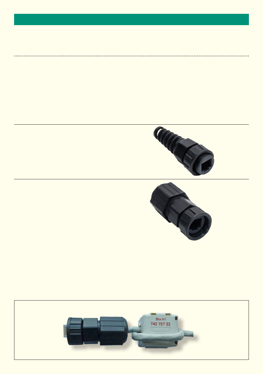
ETHERNET INTERFACE
An optional Cat 6 Ethernet interface is provided on product connector 2. The 350 radar requires it be connected
to a network and be able to obtain an IP address through a DHCP server.
A Cat 6 interface cable is not provided for use with the product, but should it be fitted, it should be of the type:
Overall braid screened, shielded twisted pair (S/FTP). This is to ensure EMC compliance.
Connector Details:
Product Connector: RJ45 Bulkhead Connector - Amphenol P/No RCP-5SPFFH-TCU7001
The following connectors are supplied with the 350 radar:
Option 1 – Amphenol RCP-00AMMA-SLM7001
Connector needs to be assembled prior to the fitting
of the RJ45 connector. Recommended cable OD
range = 4.5mm to 6.5mm
Option 2 – Amphenol RCP-00BMMS-SLM7001 (Field installable)
Prior assembled RJ45 Ethernet cable can be fitted
into this housing (RJ45 connectors fit through and
into this connector). Recommended cable OD
range = 5.0mm to 6.5mm.
NOTE:
a) The RJ45 at the 350 end MUST NOT have any sort of boot fitted - to enable it to fit correctly into this connector.
b) The Ethernet braid shield of the external cable, at the customer equipment end, must be connected to a good
ground earth point in order to comply with EMC requirements.
c) Whichever Ethernet connector is used, the snap on ferrite (CP-07-015) which is supplied with the 350
must be fitted to the 350 end of the Ethernet cable (with 2 turns) as shown below in order to comply with EMC
requirements.
CP-07-015 Positioning
POSITION SNAP
ON FERRITE 20MM
(-0MM/+3MM) FROM THE
CABLE END TO ENSURE
COMPLIANCE WITH EMC
REQUIREMENTS
2 TURNS APPLIED TO THE
CABLE AS SHOWN
NOTE THE CONNECTOR
MAY DIFFER BUT THE 70MM
(-0MM / 3MM) DISTANCE
IS REQUIRED AS ARE THE
2 TURNS

15
SYSTEM HARDWARE OVERVIEW
POWER SUPPLY
The radar is powered using a DC voltage in the range of 10-16 Volts. The power is applied to the radar using the
multi-pin mating connector.
Reverse polarity protection is included in the design. The radar takes approximately 1A for a period of 5ms.
The radar consumes 500mA at 12vDC. Power consumption is approximately 6 Watts.
A thermal fuse with a 1.25A rating has been installed to protect against electrical short circuit fault conditions.
Power-Up Sequence
Upon initialisation from power-up or *REBOOT the radar will respond with the following message;
AGD SYSTEMS LTD AGD350
350-000-000
ARM Software version MI-164-2
DSP Software version MI-159-2
Common Platform version REL-13
FPGA version 15E000E
Power Supply Tolerance
The radar power supply is specified between 10 and 16vDC. The radar will operate outside of these parameters
but its operation is not specified. At 12vDC the current consumed is 500mA.
MATING CONNECTOR PIN OUT CONNECTIONS
Pin No. Signal Function Host Equipment Connection
1Input + Digital input for Future Expansion
2Input - Digital input for Future Expansion
3N/C Contact ---
Contacts for single opto output
4N/O Contact ---
5Common ---
6GND (RS422) RS422 ground Ground or 0V
7VIN Supply Voltage 10 – 16vDC
8GND Supply Ground
9RS422 Y (TX+) RS422 Signal RS422 A (RX+)
10 RS422 Z (TX-) RS422 Signal RS422 B (RX-)
11 RS422 B (RX-) RS422 Signal RS422 Z (TX-)
12 RS422 A (RX+) RS422 Signal RS422 Y (TX+)

1616
IMPORTANTRADAR CHARACTERISTICS
GENERAL
Radar Antenna
The antenna design is a planar patch array with the following performance;
Operating Frequency Band and Power
The radar frequency and power is as follows;
Parameter Specified Notes
Horizontal Beam-width 40˚ approx -3dB
Vertical Beam-width 20˚ approx -3dB
Side-lobe Suppression
E-Field Vertical Plane Polarised
Parameter Specified Notes
Centre Frequency (channel 1) 24.077GHz*
Centre Frequency (channel 2) 24.125GHz*
Centre Frequency (channel 3) 24.175GHz*
Centre Frequency (channel 4) 24.223GHz*
Frequency Modulation (FM) 44MHz
Power <100mW eirp
Field Strength
ITU Code 44M0FXN
*Proposed channels for U.S, channel 1 - 24.102GHz, channel 2 - 24.148GHz.

1717
IMPORTANTRADAR CHARACTERISTICS
FREQUENCY VARIANTS
Several versions of this product are available at frequency options which are for use in different
geographic regions related to the radio requirements of that specific jurisdiction as follows;
Frequency Variant EU Country of Use Other Countries Notes
24.050GHz to
24.250GHz*
*For U.S special build
variant required.
Proposed U.S channels
channel 1 - 24.102GHz
channel 1 - 24.148Ghz
This table is periodically updated: if the required country is not shown please enquire on availability.
These products may not be used in the following geographic regions;
Restriction Type EU Country Other Countries
Relevant 24GHz Band not allocated
Licence Required for Use
Frequency Allocated but EIRP too high
It is important to note that this table is updated from time to time. Please contact AGD for latest
information if your intended country of use is not currently represented.
(Note: Countries are listed by their ISO 3166 2 letter code)
none currently identified
This device complies with Part 15 of the FCC Rules. Operation is subject to the following two conditions:
(1) This device may not cause harmful interference, and
(2) This device must accept any interference received, including interference that may cause undesired operation.
This equipment complies with FCC radiation exposure limits set forth for an uncontrolled environment. End users must follow the specific
operating instructions for satisfying RF exposure compliance. such that the module should not be installed in equipment intended to be used
within 20cm of the body.
This transmitter must not be co-located or operating in conjunction with any other antenna or transmitter.
Changes or modifications not expressly approved by the party responsible for
compliance could void the user's authority to operate the equipment

18
RADAR CHARACTERISTICS
ANTENNA PLOTS

19
RADAR COMMANDS
RADAR COMMAND OVERVIEW
Commands are used to control the operation of radar. These can be sent over the RS422 UART Link.
(Ethernet available at a later date)
Commands are immediately followed by an operator that indicates the required action. Not all the operators
are supported for all commands. Where an operator is used and it is not supported the radar will respond with
warning message. The table shows the commands used by the radar.
Operator Operation
= Set a parameter to a value e.g. *LS=50<CR>
? Respond with value or values
^ Set default value for parameter
$ Provide help on the command
! Do something e.g. *REBOOT! Reboots the radar

20
RADAR COMMANDS
RADAR COMMAND LIST
Command Type Function Default
Value Min
Value Max
Value Units, Resolution or
Values
AGD Displays the product information and firmware /
software revisions n/a n/a n/a Text Display
*BAUD ?/= Enquire / Set the baud rate of the radar. The
program is stored in non-volatile memory and is
used the next time the radar is powered on.
*BAUD =<baud>, <flow control>, <parity>,
<number of data bits>
e.g.*baud=115200,0,NONE,8
921600
Flow
Control 0
Parity ODD
Number of
data bits 8
2400 921600 Baud Rate Values: 2400,
4800, 9600, 19200, 38400,
57600,115200, 230400, 460800,
921600
Flow Control: 0=no control
1=flow control
Number of data bits 7,8
*CD ?Enquire the calibration date DD,MM,YYYY
*CRC32 ?Calculates and verifies the 32 bit CRC code and
data checksums
*CHAN ?/= Enquire / Set the transmit channel 3 1 4 1-4
1-24.075
2-24.175
3-24.125
4-24.225
(4 channel variant)
*CT ?/= Enquire / Set the co-ordinate type used in the
target detection messages P P C P = Polar
C = Cartesian
*DIR ?/= Enquire / Set the radar direction mode AA R A= Advancing
R= Receding
B= Bi-Directional
N= No Detection
*ETPn
(n=1 or 2) ?/= /^ Enquire / Set an Event Trigger Point at a defined
range 20 6
(0 = off) 84 1 metre
*ETPnLST
(n=1 or 2) ?/= /^ Enquire / Set the optional Event Trigger Point
Low Speed Threshold 10 10 249 KPH
units change depending on speed
units (see *SU)
*ETPnHST
(n=1 or 2) ?/= /^ Enquire / Set the optional Event Trigger Point
High Speed Threshold 250 11 250 KPH
units change depending on speed
units (see *SU)
*ETPnDIR
(n=1 or 2) ?/= /^ Enquire / Set the optional Event Trigger Point
Direction.
NOTE: The *DIR command must also be set to
allow the required Event Trigger Point direction
otherwise the event will not be triggered.
B A R A = Approaching
R = Receding
B = Bi-directional
*ETPnLPT
(n=1 or 2) ?/= /^ Enquire / Set the optional Event Trigger Point
Low Threshold Power (target amplitude) 65 55 109 dB
(ref Target amplitude values in
Target Detect message)
*ETPnHPT
(n=1 or 2) ?/= /^ Enquire / Set the optional Event Trigger Point
High Power Threshold (target amplitude) 110 56 110 dB
(ref Target amplitude values in
Target Detect message)
*HBP ?/= Enquire / Set the heartbeat period 60 0 (off) 86400 1 second
*HELP Lists all commands along with command help
information
*HOLD ? / = /^ Enquire / set the hold time of the opto output.
Opto output is triggered on ETP1 0.5 0.1 10 seconds
*HR ? / = /^ Enquire / set the High Range threshold 85 20 85 metres
*HS ? / = /^ Enquire / set the High Speed Threshold 250 40 250 KPH
(Units change depending on
speed units (see *SU)
*HS ? / = /^ Enquire / set the High Speed Threshold 250 40 250 KPH
(Units change depending on
speed units (see *SU)

21
RADAR COMMANDS
RADAR COMMAND LIST
Command Type Function Default
Value Min
Value Max
Value Units, Resolution or
Values
*IP ?/=/^ Not Currently Enabled
*LR ? / = /^ Enquire / set the Low Range Threshold 4 4 40 metres
*LS ? / = /^ Enquire / set the Low Speed Threshold 10 10 160 KPH
(Units change depending on
speed units (see *SU)
*MSG ?/= /^ Enquire / Set the message type displayed on
the output 2 2 4 2 = Target Detect Message
3 = Event Trigger Point
Message (only)
4 = Tracked Target Messages
(and event trigger point message
if event trigger point enabled)
*REBOOT !Force a reboot of the radar
*SN ?Read the serial number of the radar
*TEXT ?/= Read / Write free form text to non-volatile
memory
*TEMP ?Reports the temperature measured inside
the radar ºC
*VER ?Provides the product number, firmware
version and date
*SU ? / = Enquire / set the speed units used in the
messages. K K M K = KPH
M = MPH
*THRESHOLD ? / = /^ Enquire / set the detection power threshold.
Caution: setting this value too high may make
the radar deaf. Setting it too low may make the
radar very noisy
85 55 120 dB
22
MESSAGE FORMATS
RADAR EVENT MESSAGES
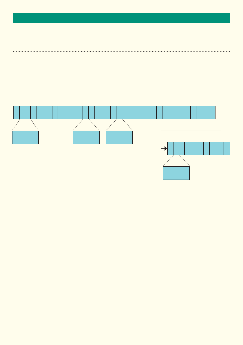
Detect Message / 02 Message
The detect message outputs the raw data for targets as identified by the radar. Each valid target is output as a
message conforming to the structure below.
This message output is activated using the *MSG=02 command.
MT ,
S
T
X, ,
,
, ,
,
D U
C
, , ,
*E
T
X
Message
Time Target
Number Number
of Targets
Target
Amplitude
Speed Range to Target
OR
Y-range to Target
Angle of Arrival
OR
X-range to Target
Check
Sum
2 11 1 1
1
1 1
1
1 1
1
1 1 1
1 1
8 2 2
5
5 5 5
2
Speed Units
Coorindinate
Type
Direction
A, R, X or Y
Message Type
02

23
MESSAGE FORMATS
RADAR EVENT MESSAGES
Detect Message / 02 Message Format
Name Size / Bytes Value Notes
STX 1 2 Start of message byte
MT 202 Message Type
, 1 ‘,’ Comma
Message Time 8DDDDD.DD Time of message in seconds.
0 to 86400.00 seconds
, 1 ‘,’ Comma
Target Number 2XX Target number
, 1 ‘,’ Comma
Number of
Targets
2XX Total number of targets detected in
the current frame.
, 1 ‘,’ Comma
Direction
‘D’
1‘A’ = Approaching Target
‘R’ = Receding Target
‘X’ = Simulated approaching target
‘Y’ = Simulated receding target
Direction the target is travelling.
, 1 ‘,’ Comma
Speed 5‘DDD.D’ Target speed to one decimal place
in decimal format
, 1 ‘,’
Speed Units
‘U’
1‘M’ = MPH
‘K’ = KPH
The speed units used for the
measurement
, 1 ‘,’ Comma
Range to Target
OR
Y-range to Target
5 ‘DDD.D’ Target range in metres OR
Y-range to target in metres
(depending on Coordinate Type)
, 1 ‘,’ Comma
Angle of Arrival
OR
X-range to Target
5‘±DD.D’ Angle of Arrival in degrees OR
X-range to target in metres
(depending on Coordinate Type)
, 1 ‘,’ Comma
Coordinate Type
‘C’
1‘P’= Polar
‘C’= Cartesian
Coordinate Type used for positional
information
, 1 ‘,’ Comma
Target Amplitude 5 ‘DDD.D’ Target Power Amplitude in dB
* 1 ‘*’ Asterisk
Check Sum 2‘XX’ Check sum in hexadecimal format
ETX 1 3 End of message byte
24
MESSAGE FORMATS
RADAR EVENT MESSAGES
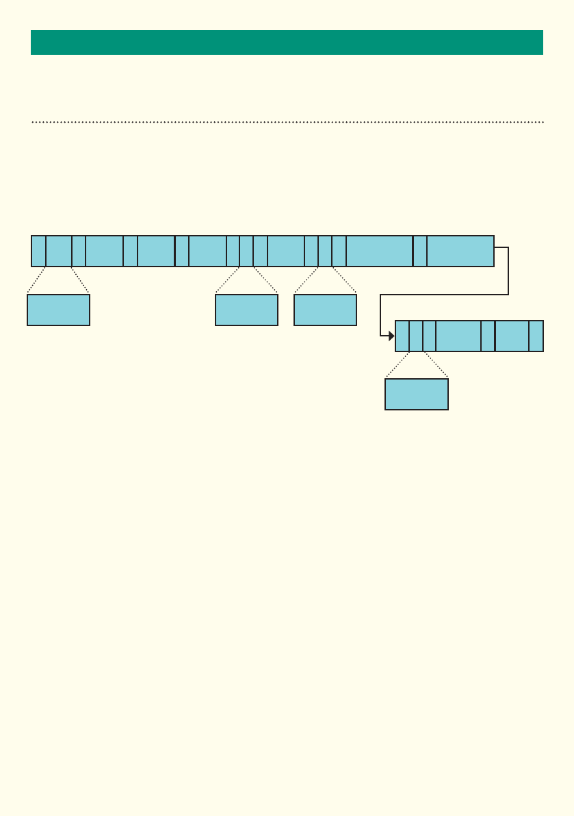
Event Trigger Point Message / 03 Message
The event trigger point message is output from the radar when a user defined trigger point in the radars field of
view has been set by the user and is activated by a target.
An Event Trigger Point can be configured using the ‘*ETPn’ message and further qualified with the optional
messages (e.g. ‘*ETPn_LST’).
This message output is activated using the *MSG=03 command.
MT ,
S
T
X, ,
,
, ,
,,
D U
C
, , ,
*E
T
X
Message
Time Event Trigger
Point Number
Tracked
Target
Number
Target
Amplitude
Target
Bearing
Speed Range to Target
OR
Y-range to Target
Angle of Arrival
OR
X-range to Target
Check
Sum
2 11 1 1
1
1 1
11
1 1
1
1 1 1
1 1
8 2 2
55
5 5 5
2
Speed Units
Coorindinate
Type
Direction
A, R, X or Y
Message Type
03

25
MESSAGE FORMATS
RADAR EVENT MESSAGES
Event Trigger Point Message / 03 Message Format
Name Size / Bytes Value Notes
STX 1 2 Start of message byte
MT 203 Message Type
, 1 ‘,’ Comma
Message Time 8DDDDD.DD Time of message in seconds.
0 to 86400.00 seconds
, 1 ‘,’ Comma
Event Trigger Point
Number 1XX The Event Trigger Point Number
, 1 ‘,’ Comma
Tracked Target
Number 21 or 2 The identity of the tracked target
, 1 ‘,’ Comma
Direction
‘D’ 1‘A’ = Approaching Target
‘R’ = Receding Target
‘X’ = Simulated approaching target
‘Y’ = Simulated receding target
Direction the target is travelling.
, 1 ‘,’ Comma
Speed 5‘DDD.D’
Target speed to one decimal place in decimal format
, 1 ‘,’
Speed Units
‘U’ 1‘M’ = MPH
‘K’ = KPH The speed units used for the measurement
, 1 ‘,’ Comma
Range to Target OR
Y-range to Target 5 ‘DDD.D’ Target range in metres OR Y-range to target in
metres (depending on Coordinate Type)
, 1 ‘,’ Comma
Angle of Arrival OR
X-range to Target 5‘±DD.D’ Angle of Arrival in degrees OR X-range to target
in metres (depending on Coordinate Type)
, 1 ‘,’ Comma
Target Bearing 5DDD.D The bearing of the target in degrees relative
to the radar.
0° is a target travelling directly away from the
radar
90° is a target travelling from left to right across
the radar
180° is a target travelling directly towards the
radar
270° is a target travelling from right to left across
the radar
, 1 ‘,’ Comma
Coordinate Type ‘C’ 1‘P’= Polar
‘C’= Cartesian Coordinate Type used for positional information
, 1 ‘,’ Comma
Target Amplitude 5 ‘DDD.D’ Target Power Amplitude in dB
* 1 ‘*’ Asterisk
Check Sum 2‘XX’ Check sum in hexadecimal format
ETX 1 3 End of message byte
26
MESSAGE FORMATS
RADAR EVENT MESSAGES
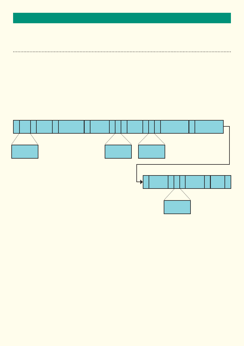
Tracked Target Message / 04 Message
This function creates the Tracked Target message type. The raw target data is filtered so that only tracked target
data is output.
This message output is activated using the *MSG=04 command.
MT ,
S
T
X, ,
,
, ,
,
D U
C
, , ,
*E
T
X
Message
Time Track
Number Target
Bearing
Target
Amplitude
Speed Range
OR
Y-range to Target
Angle of Arrival
OR
X-range to Target
Check
Sum
2 11 1
1
1 1
1
1 1
1
1 1 1
1 1
8 2
5
5 5 5
2
Speed Units
Coorindinate
Type
Direction
A, R, X or Y
Message Type
04

27
MESSAGE FORMATS
RADAR EVENT MESSAGES
Tracked Target Message / 04 Message Format
Name Size / Bytes Value Notes
STX 1 2 Start of message byte
MT 204 Message Type
, 1 ‘,’ Comma
Message Time 8DDDDD.DD Time of message in seconds.
0 to 86400.00 seconds
, 1 ‘,’ Comma
Track Number 1XX Track Number
, 1 ‘,’ Comma
Direction
‘D’ 1‘A’ = Approaching Target
‘R’ = Receding Target
‘X’ = Simulated approaching target
‘Y’ = Simulated receding target
Direction the target is travelling.
, 1 ‘,’ Comma
Speed 5‘DDD.D’ Target speed to one decimal place in
decimal format
, 1 ‘,’
Speed Units
‘U’ 1‘M’ = MPH
‘K’ = KPH The speed units used for the
measurement
, 1 ‘,’ Comma
Range to Target
OR
Y-range to Target
5 ‘DDD.D’ Target range in metres OR
Y-range to target in metres
(depending on Coordinate Type)
, 1 ‘,’ Comma
Angle of Arrival
OR
X-range to Target
5‘±DD.D’ Angle of Arrival in degrees OR
X-range to target in metres
(depending on Coordinate Type)
, 1 ‘,’ Comma
Target Bearing 5DDD.D The bearing of the target in degrees
relative to the radar.
0° is a target travelling directly away
from the radar
90° is a target travelling from left to
right across the radar
180° is a target travelling directly
towards the radar
270° is a target travelling from right to
left across the radar
, 1 ‘,’ Comma
Coordinate Type ‘C’ 1‘P’= Polar
‘C’= Cartesian Coordinate Type used for positional
information
, 1 ‘,’ Comma
Target Amplitude 5 ‘DDD.D’ Target Power Amplitude in dB
* 1 ‘*’ Asterisk
Check Sum 2‘XX’ Check sum in hexadecimal format
ETX 1 3 End of message byte
28
MESSAGE FORMATS
RADAR EVENT MESSAGES
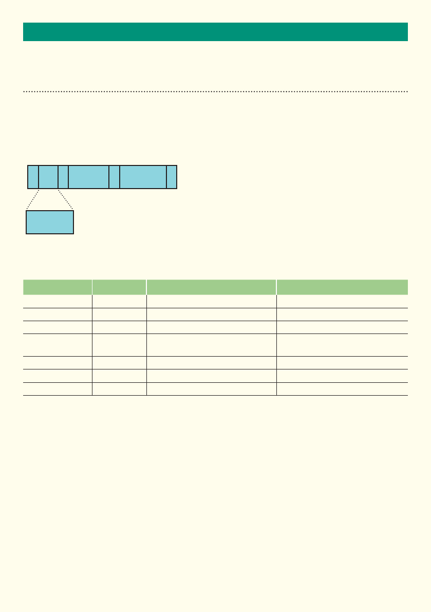
Heart Beat Message / ‘HB’
This message is sent each time the heart beat period expires. The heart beat message period is controlled using
the *HBP command. The heart beat period is measured in frames.
Heart Beat Message Format
Notes to Heart Beat Message
The heartbeat period is set in seconds using the *HBP command. Setting the hearbeat period to 0 secs will turn
the hearbeat off. The maximum setting for the heartbeat period is 86400 secs.
Name Size / Bytes Value Notes
STX 1 2 Start of message byte
MT 2‘HB’ = Heart Beat Message type
, 1 ‘,’ Comma
Message Time 8DDDDD.DD Time of message in seconds.
0 to 86400.00 seconds
* 1 ‘*’ Asterisk
Check Sum 2‘XX’ Check sum in hexadecimal format
ETX 1 3 End of message byte
MT ,
S
T
X*E
T
X
Message
Time Check
Sum
2 11 1 18 2
Message Type
HB

RoHS
COMPLIANT
Restriction on
Hazardous Substances
29
TECHNICAL SPECIFICATIONS
SPECIFICATIONS
Technology Phase Mono-Pulse FMCW
Radiated Power <100mW EIRP (<20dBm)
Transmit Frequency 24.050 – 24.250GHz
Transmit Bandwidth 44MHz
Range 4 to 85m
Mounting Flange fixings, tripod mount or optional foot bracket (MS-205)
Mounting Height 3 - 5.5m nominal
Speed Range 10 to 250 kph
Horizontal Field of View ±20º from centre bore of radar
Vertical Field of View ±10º from centre bore of radar
Measurement Frame Rate 100 frames per second
Weight TBC
Housing Material Black Polycarbonate
Housing Finish Self coated black
Sealing IP66
Operating Temperature -30°C to +70°C
Power Nominal 6W (Typically 500mA @ 12Vdc)
Power Supply 10 -16Vdc
Radar Output RS422 (Ethernet provision for future)
MTBF 20 years
EMC Specification ETSI EN 301 489 / BS EN 50293
Radio Specification ETSI 300.440, FCC CFR47 Part 15.245
Patent No. Patent applied for
Owing to the Company’s policy of continuous improvement, AGD Systems
Limited reserves the right to change their specification or design without
notice.
This device complies with Part 15 of the FCC Rules. Operation is subject to the following two conditions:
(1) This device may not cause harmful interference, and
(2) This device must accept any interference received, including interference that may cause undesired operation.
This equipment complies with FCC radiation exposure limits set forth for an uncontrolled environment. End users must follow the
specific operating instructions for satisfying RF exposure compliance. such that the module should not be installed in equipment
intended to be used within 20cm of the body. This transmitter must not be co-located or operating in conjunction with any other
antenna or transmitter.
Changes or modifications not expressly approved by the party responsible for
compliance could void the user's authority to operate the equipment
152mm
54.92mm
54.92mm
214mm
152mm
54.92mm
54.92mm
214mm
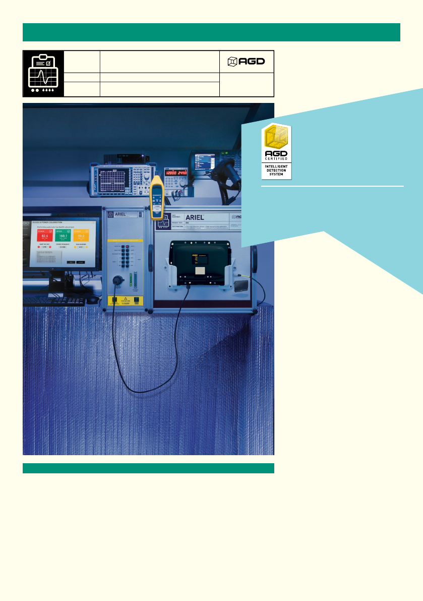
LIFETIME PRODUCT TRACEABILITY
There are clearly defined pass and fail criteria at all stages within the Ariel test
process. The test results in association with the product build revision are recorded
on a product serial number basis. The full suite of test measurements is instantly
sent to the dedicated product database within the AGD secure server facility,
providing full traceability during the product lifetime.
The AGD Certified symbol is your mark of assured performance.
TEST
EQUIPMENT:
TEST FUNCTION:
PRODUCT TEST:
ARIEL was designed and developed
by AGD Systems
ARIEL was designed and developed
by AGD Systems
ARIEL
INTELLIGENT DETECTION SYSTEMS
350
350
• True range simulation of target
• Test cycle time 9 minutes
• Radar target processing optimisation
• Verification of communication protocols
• True range simulation of target
• Test cycle time 9 minutes
• Radar target processing optimisation
• Verification of communication protocols
TM
ARIELTM
TEST
EQUIPMENT:
TEST FUNCTION:
PRODUCT TEST:
INTELLIGENT DETECTION SYSTEMS
FULL
RANGE
Ariel is dedicated to the testing of the
AGD portfolio of ‘ranging’ FMCW vehicle radars.
It provides true range simulation and both target
speed and direction simulation at a
given range
Ariel™ is a bespoke set of test
equipment designed and developed
by AGD Systems. It is dedicated to the
testing of the AGD portfolio of ‘ranging’
FMCW vehicle radars. 100% of the 350
units manufactured at AGD are
Certified by Ariel.
The key test
functions performed
by Ariel to Certify the
premium performance of your
Intelligent Detection System are:
• True range simulation of target
• Target speed and direction simulation
at a given range
• Radar target processing optimisation
• Transmitted radar frequency
modulation measurement
• Verification of interface and
communication protocols
• Test cycle time of 9 minutes
The radar test sequences performed
by Ariel on the radar under test
provides a thorough examination of
the performance of the 350 radar and
specifically the ranging measurement
capability provided by the FMCW
technology deployed. This gives full
control of simulated targets’ signal
size, speed, direction and range.
Optimisation of frequency signals on
Ariel ensures full compatibility with
country requirements within the 24GHz
radar operating band.
MANUFACTURING TEST PROCESS
30
3131
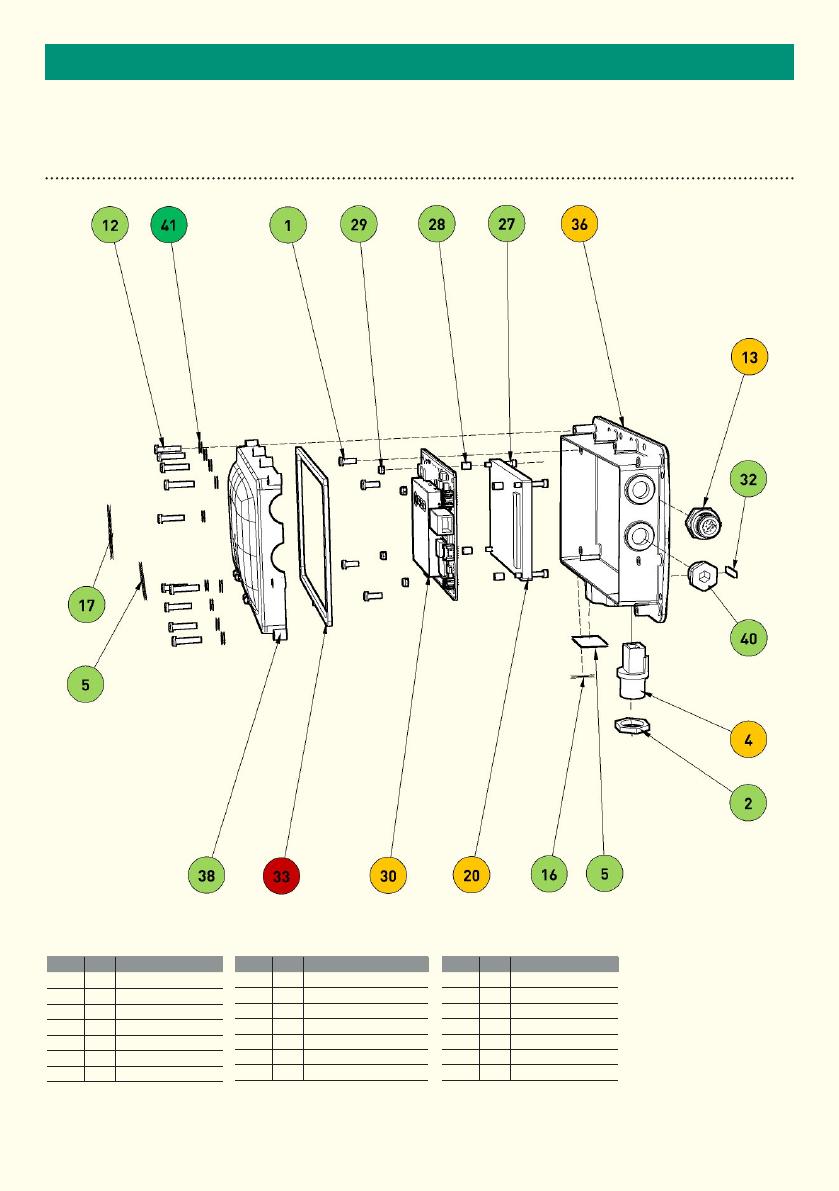
IMPORTANTEND OF LIFE – DISPOSAL INSTRUCTIONS (EOL)
Item Qty Material
1 4 Stainless steel
5 2 Polyester
12 10 Steel
13 1Cable Assembly
15 2Polyester
17 1Generic
20 1Zinc/PCB Assembly
Item Qty Material
27 4Stainless Steel
28 4Aluminum
29 4Stainless Steel
30 1PCB Assembly
33 1Neoprene - Closed Cell
36 1Polycarbonate/Brass
38 1Polycarbonate
Item Qty Material
40 1Nylon 6
4 1 Nylon 6 / Metal
2 1 Nylon 6
32 1Polyester
41 10 Cellulose Fill
• Reuse / Recycle
• Separate & Recycle
• Downcycle
• Hazardous Recovery
• Non- Recyclable
This document serves as a guideline only for EOL procedures and further guidance may need to be sought from the appropriate authority or agency.
AGD350 RADAR TRAFFIC DETECTOR

32
IMPORTANT
SAFETY PRECAUTIONS
All work must be performed in accordance with company working practices, in-line with adequate risk
assessments. Only skilled and instructed persons should carry out work with the product. Experience and safety
procedures in the following areas may be relevant:
• Working with mains power
• Working with modern electronic/electrical equipment
• Working at height
• Working at the roadside or highways
1. This product is compliant to the Restriction of Hazardous Substances (RoHS - European Union directive
2011/65/EU).
2. Should the product feature user-accessible switches, an access port will be provided. Only the specified
access port should be used to access switches. Only non-conductive tools are to be used when operating
switches.
3. The product must be correctly connected to the specified power supply. All connections must be made
whilst the power supply is off or suitably isolated. Safety must take always take precedence and power
must only be applied when deemed safe to do so.
4. No user-maintainable parts are contained within the product. Removing or opening the outer casing is
deemed dangerous and will void all warranties.
5. Under no circumstances should a product suspected of damage be powered on. Internal damage may be
suggested by unusual behaviour, an unusual odour or damage to the outer casing. Please contact AGD
for further advice.
6. This device complies with Part 15 of the FCC Rules. Operation is subject to the following two conditions:
(1) This device may not cause harmful interference, and
(2) This device must accept any interference received, including interference that may cause undesired operation.
This equipment complies with FCC radiation exposure limits set forth for an uncontrolled environment. End users must follow the
specific operating instructions for satisfying RF exposure compliance. This transmitter must not be co-located or operating in
conjunction with any other antenna or transmitter.
Changes or modifications not expressly approved by the party responsible for
compliance could void the user's authority to operate the equipment

33
IMPORTANT
IMPORTANT INFORMATION
Low Power Non-Ionising Radio Transmission and Safety
Concern has been expressed in some quarters that low power radio frequency transmission may constitute
a health hazard. The transmission characteristics of low power radio devices is a highly regulated environment
for the assurance of safe use.
There are strict limits on continuous emission power levels and these are reflected in the testing specifications
that the products are approved to. These type approval limits are reflected in the product specifications required
for a typical geographic area such as those for the EU (ETS300:440), for the USA (FCC part 15c) and for Australia/
New Zealand (AS/NZS 4268). The limits adopted in these specifications are typically replicated in many other
localized specifications.
The level of safe human exposure to radio transmission is given by the generally accepted guidelines issued by
the International Commission on Non-Ionizing Radiation Protection (ICNIRP). This body has issued guidance
for limiting exposure to time-varying electric, magnetic and electromagnetic fields (up to 300 GHz) which are
quoted below.
Note 1 Values are calculated conversions for comparison purposes.
Note 2 Other equivalent limits include; Medical Research Council Limit of 10mW/cm2, IACP limit of 5mW/cm2 (at 5cm) and
UK CAST limit of 5mW/cm2. . Power density at the radome typically 4µW/cm2. .
Note 3 Calculation is made on the assumption antenna is a point source therefore the actual value is likely to be significantly
less than that quoted. Note that a theoretical max level at a 5cm distance (which gives 0.318mW/cm2) is at a point in
the field where the radar beam is not properly formed.
Note 4 Comparison for product model 350 operating in the band typically 24.050GHz to 24.250GHz
From the table it can be seen that it is extremely unlikely that a potentially hazardous situation could occur owing
to the use of such low power devices.
It is considered to be good practice not to subject humans to radiation levels higher than is necessary. In a works
environment where multiple equipment on soak test are to be encountered then it is considered good practice to
contain the equipment in an appropriate enclosure lined with radar absorbing material.
Radar and ICNIRP limit comparison Typical Informative Limits for Radar
Transmission Approval
Radar
Transmitted
Level (Note 4)
ICNIRP Limit
(Table 6)
Exposure
Margin
ETS300:440
FCC (part15c)
AS/NZS 4268
Power
(mW EIRP)
<100mW
(<20dBm)
N/A N/A 100mW
(20dBm)
1875mW
(Note 1)
100mW
(20dBm)
Max Power
Density
(mW/cm2)
3.18µW/cm2
at 50cm
(Note 3)
<50W/m2
(5mW/cm2)
(Note 2)
0.064%
N/A
N/A
N/A
Field Strength
(V/m) at 3m
<0.58V/m
(5.8mV/cm)
(Note 1)
<137V/m
(1370mV/cm)
0.42%
0.58V/m
(5.8mV/cm)
(Note 1)
2500mV/m
(25mV/cm)
0.58V/m
(5.8mV/cm)
(Note 1)

NOTES

NOTES

DISCLAIMER
While we (AGD Systems) endeavour to keep the information in this manual correct at the time of print, we make no
representations or warranties of any kind, express or implied, about the completeness, accuracy, reliability, suitability
or availability with respect to the information, products, services, or related graphics contained herein for any purpose.
Any reliance you place on such information is therefore strictly at your own risk. In no event will we be liable for any loss
or damage including without limitation, indirect or consequential loss or damage, or any loss or damage whatsoever
arising from loss of data or profits arising out of, or in connection with, the use of this manual.
WARRANTY
All AGD products are covered by a 12 month return to factory warranty. Products falling outside this period may
be returned to AGD Systems for evaluation, repair, update or re-calibration, any of which may be chargeable.
AGD Systems Limited
White Lion House T: +44 (0)1452 854212
Gloucester Road, F: +44 (0)1452 854213
Staverton, Cheltenham E: sales@agd-systems.com
Gloucestershire, GL51 0TF, UK W: agd-systems.com
ISO 14001
Registered
Environmental
Management015
ISO 9001
Registered
Quality
Management015
©AGD Systems Limited 2015 Doc. Ref. 350 PM ISS 2