AGL A710 Multipurpose Laser User Manual GENERAL INFORMATION
AGL Corporation Multipurpose Laser GENERAL INFORMATION
UserManual.wiki
>
AGL
>
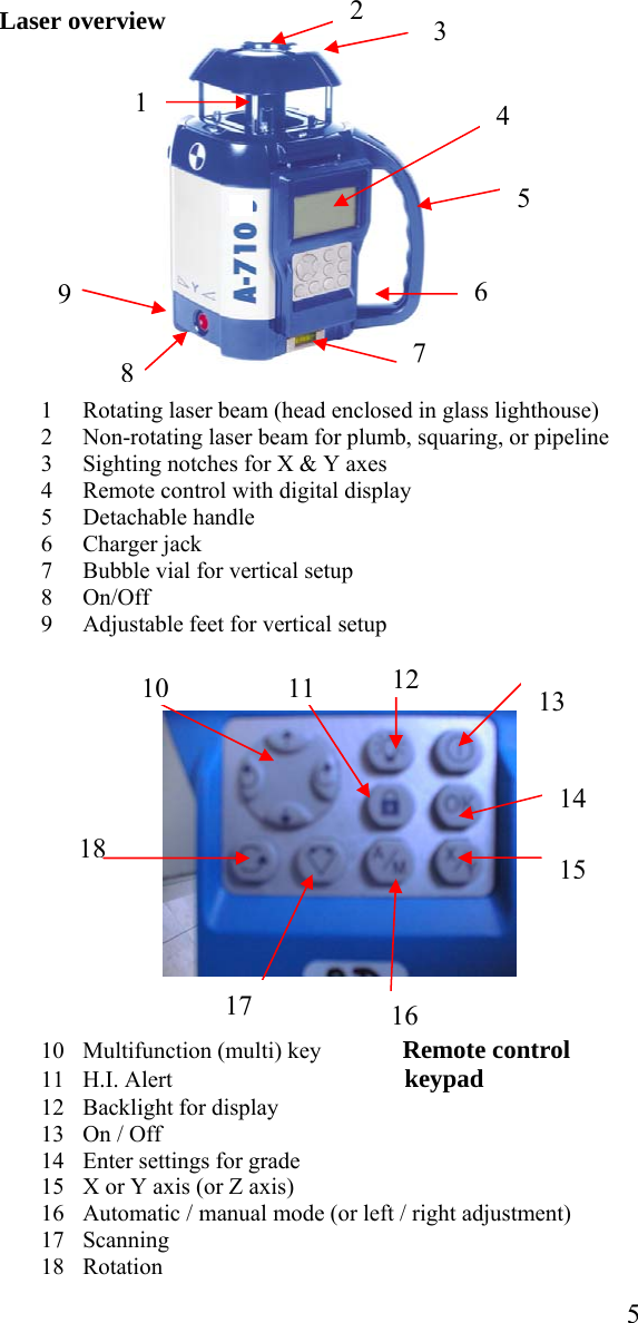
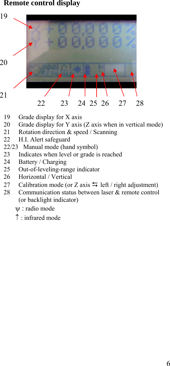
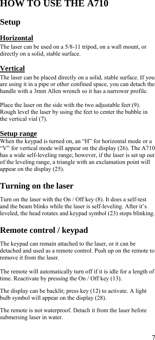
A710 User Manual
User manual
Navigation menu
Upload a User Manual
Namespaces
Wiki Guide
HTML
PDF
Info
Views
User Manual
Discussion / Help
Navigation