AGL A710 Multipurpose Laser User Manual GENERAL INFORMATION
AGL Corporation Multipurpose Laser GENERAL INFORMATION
AGL >
User manual
A710
Multipurpose Laser
Owner’s Manual
2
GENERAL INFORMATION
Thank you for buying the Agatec A710 laser! Although the A710 is
simple to use, we recommend that you read this manual before
operating the laser.
Description
The A710 is a visible universal laser that can be used for leveling,
vertical alignment, squaring, and single and dual slope grade control.
It has a digital grade display and is ideal for machine control and
other dual grade applications. It’s totally waterproof and has a beam
designed for pipelaying. It also has scanning and constant squaring
for interior jobs.
Other advanced features include: totally automatic self-leveling in
both horizontal and vertical modes; electronic calibration by the
user; and a detachable keypad that can be used as a remote control.
Specifications
Recommended use 1,000 ft. (300 m) diameter
Accuracy ± 3/16” at 100 ft.
Leveling range ± 10% in X and Y axes
Grade range -10% to +10% in X,Y & Z axes
Rotation speeds 60, 150, 300, 450, 600, 720 rpm
Scanning lengths Choice of 3
Laser battery NiMh rechargeable
Charging time 15 hours
Battery life 40 hours
Remote control batteries 2 AAA alkaline
Dimensions 5” x 4 ½” x 8 1/2”
12.5 x 11.5 x 21.9 cm
Weight 7 ¾ lbs. (3.5 kg)
Environmental Laser is waterproof: IP67
Remote control is weather-
resistant
Laser Diode Visible 635 nm, <5mW
CDRH/IEC Classification Class 3R
Radio Frequency Interference
WARNING: This equipment complies with Part 15 of the FCC
rules. Any changes or modifications not expressly approved by the
manufacturer could void the user’s authority to operate the
equipment.
Operation is subject to the following two conditions: (1) this device
may not cause harmful interference, and (2) this device must accept
any interference received, including interference that may cause
undesired operation.
This equipment has been tested and found to comply with the limits
for a Class B digital device, pursuant to Part 15 of the FCC rules.
These limits are designed to provide reasonable protection against
harmful interference in a residential installation. This equipment
generates, uses, and can radiate radio frequency energy and, if not
installed and used in accordance with the instructions, may cause
harmful interference to radio communications. However, there is no
guarantee that interference will not occur in a particular installation.
If this equipment does cause harmful interference to radio or
television reception, which can be determined by turning the
equipment off and on, the user is encouraged to try to correct the
interference by one or more of the following measures:
Reorient or relocate the receiving antenna
Increase the separation between the equipment and receiver
Connect the equipment into an outlet on a circuit different from
that to which the receiver is connected
Consult the dealer or an experienced radio/TV technician for help
Notice for Canada
This Class B digital device meets all requirements of Canadian
Radio Standards Specification RSS-210.
Cet appareil numérique de la Class B respecte toutes les exigences
du Règlement sur le matériel brouilleur du Canada.
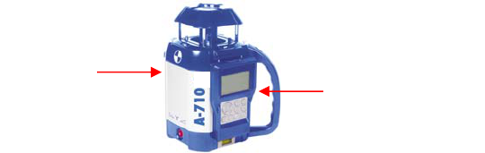
Location of FCC labels
FCC
label
(back of
laser)
FCC label
(back of
detachable remote
control/keypad)
3
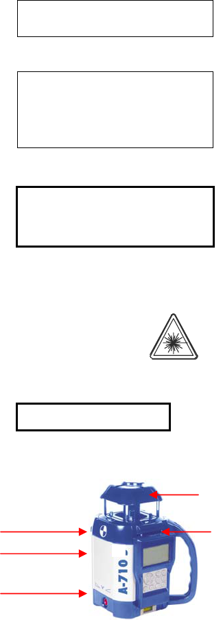
Safety Labels
Back of laser:
A CDRH label
COMPLIES WITH 21CFR 1040.10 AND 1040.11
EXCEPT FOR DEVIATIONS PURSUANT TO
LASER NOTICE No. 50, DATED JULY 26, 2001
B Serial no. tag
AGL
Model
P/N
2202 Redmond Rd. P.O. Box 189, Jacksonville, AR 72076
C Explanatory label
CLASS 3R LASER PRODUCT
WAVE LENGTH 630-680 nm
MAX. OUTPUT POWER: 5mW
LASER LIGHT; AVOID DIRECT EYE EXPOSURE
CONFORMS TO IEC 60825-1; 2001
Front of laser
with keypad:
D Warning label
E Aperture label
AVOID EXPOSURE. LASER LIGHT
IS EMITTED FROM THIS APERTURE
D
E
A
B
C
4
5
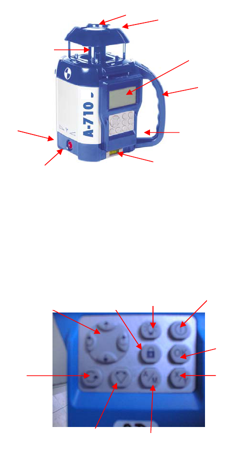
Laser overview
6655
23
8
7
1
5
6
4
9
1 Rotating laser beam (head enclosed in glass lighthouse)
2 Non-rotating laser beam for plumb, squaring, or pipeline
3 Sighting notches for X & Y axes
4 Remote control with digital display
5 Detachable handle
6 Charger jack
7 Bubble vial for vertical setup
8 On/Off
9 Adjustable feet for vertical setup
13
12
10
11
14
18
15
10 Multifunction (multi) key Remote control
17 16
11 H.I. Alert keypad
12 Backlight for display
13 On / Off
14 Enter settings for grade
15 X or Y axis (or Z axis)
16 Automatic / manual mode (or left / right adjustment)
17 Scanning
18 Rotation
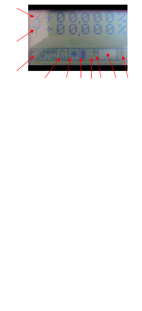
Remote control display
19
20
19 Grade display for X axis
20 Grade display for Y axis (Z axis when in vertical mode)
21 Rotation direction & speed / Scanning
22 H.I. Alert safeguard
22/23 Manual mode (hand symbol)
23 Indicates when level or grade is reached
24 Battery / Charging
25 Out-of-leveling-range indicator
26 Horizontal / Vertical
27 Calibration mode (or Z axis ' left / right adjustment)
28 Communication status between laser & remote control
(or backlight indicator)
ψ : radio mode
↑ : infrared mode
22
23
24
25
26
27
28
21
6

7
HOW TO USE THE A710
Setup
Horizontal
The laser can be used on a 5/8-11 tripod, on a wall mount, or
directly on a solid, stable surface.
Vertical
The laser can be placed directly on a solid, stable surface. If you
are using it in a pipe or other confined space, you can detach the
handle with a 3mm Allen wrench so it has a narrower profile.
Place the laser on the side with the two adjustable feet (9).
Rough level the laser by using the feet to center the bubble in
the vertical vial (7).
Setup range
When the keypad is turned on, an “H” for horizontal mode or a
“V” for vertical mode will appear on the display (26). The A710
has a wide self-leveling range; however, if the laser is set up out
of the leveling range, a triangle with an exclamation point will
appear on the display (25).
Turning on the laser
Turn on the laser with the On / Off key (8). It does a self-test
and the beam blinks while the laser is self-leveling. After it’s
leveled, the head rotates and keypad symbol (23) stops blinking.
Remote control / keypad
The keypad can remain attached to the laser, or it can be
detached and used as a remote control. Push up on the remote to
remove it from the laser.
The remote will automatically turn off if it is idle for a length of
time. Reactivate by pressing the On / Off key (13).
The display can be backlit; press key (12) to activate. A light
bulb symbol will appear on the display (28).
The remote is not waterproof. Detach it from the laser before
submersing laser in water.

8
Choice of transmission
There is two-way communication between the laser and the
remote control. If the remote is within range and properly
communicating with the laser, a symbol (ψ or ↑ ) will appear
on the display (28).
The remote signal can be either radio frequency (RF/ψ) or
infrared (IR/↑ ). RF is the default when the laser is turned on.
All laser functions will work in RF or IR mode.
Radio frequency
Turn on the remote control / keypad with the On / Off key (13).
An antenna ψ (28) indicates it is in RF mode.
Infrared
To switch to IR transmission:
1 Turn off the remote control and the laser.
2 Turn on the laser again, pressing the On / Off for at least 3
seconds until the head rotates and the beam comes on.
3 Turn on the remote control, holding the On / Off key (13)
for at least 3 seconds until the display is lit.
4 An arrow ↑ on the display (28) indicates it’s in IR mode.
If the symbol does not appear, verify there’s a clear line-of-sight
between the laser and remote control when using IR
transmission.
Automatic / manual mode
The laser is in automatic self-leveling mode when turned on.
To put in manual mode, hold down the A / M key (16) for a few
seconds. A blinking hand symbol will appear on the display
(between 22 & 23), indicating that you’re in manual mode.
You cannot enter manual mode if you’re using H.I. Alert.
CAUTION: In manual mode, the beam rotates even if the laser
is not leveled.

H.I. Alert
H.I. (height of instrument) Alert stops the laser automatically if
the laser is disturbed or moved, preventing inaccurate readings.
It will function only when selected. To activate this safeguard
feature, press the “lock” key (11). A lock is also shown on the
display (22). ╭╮
If the lock is closed, it’s in the H.I. Alert mode. ▀
If the lock is open, the H.I. Alert option ╭
has not been selected. ▀
If the laser is disturbed while in H.I. Alert mode, the head will
stop rotating, the beam will turn off, and the lock symbol (22)
will blink on the display.
To start the laser rotating again, press key (11) for 3 seconds
(the lock symbol should stop blinking). The head may have
releveled itself to a new position. Check to see if the beam
elevation has changed from its original benchmark position.
The laser is no longer in H.I. Alert mode. Press key (11) to
return to H.I. Alert.
Rotation
Rotation direction
The rotation symbol (21) on the display shows the direction the
head is rotating. To change direction, press the left » or ¼
right arrows on the multifunction (multi) key (10).
Rotation speed
The head rotates at 6 speeds: 60, 150, 300, 450, 600, and 720
rpm. 300 rpm is the default setting. You can also stop the
rotation (0 rpm).
To change speeds, press the rotation key (18). RPM will blink
on the display. Press the ½ up or ¾ down arrows on multi key
(10). The speed selected is shown on the display (21).
The laser beam is more visible at slower rotation speeds. The
faster speeds (600 and 720 rpm) are required for many machine
control receiver applications.
9
Scanning
Scanning mode allows you to see the beam easier at a distance.
To switch from rotation to scan, press the scanning key (17). A
scanning symbol appears on the display (21).
The scanning beam has three lengths, shown as 1, 2, or 3 on the
display. Use the ½ up or ¾ down arrows on the multi key (10)
to change scan lengths.
Hold down the » or ¼ arrows to move the scan left or right.
To stop scanning, press the rotation key (18).
Setting horizontal grade
10
-Y
+X
+Y
-X
The two horizontal axes (X and Y) are marked near the base of
the laser. The ends of the axis are designated as + or – to
indicate opposite sides of the axis.
Do not confuse this with + (positive) or – (negative) grade.
You can select a single grade (X axis) or dual grade (both X and
Y axes) from -10% to +10%.
Positioning laser in direction of the grade
It is very important to position the laser correctly, facing the
direction of the grade. Serious errors will occur if the laser’s
axis of grade is not placed in the proper position.
Before turning the laser on, sight along the notches (3) on top of
the laser to position the axis in the direction of grade desired.
For a single grade, the X axis should be perpendicular to the
plane of the grade: +X should face toward the grade and -X (by
the laser On/Off button) will face away. For dual grade, both X
and Y axes need to be placed in the proper orientation.
11
Calculating percent of grade
Percent of grade is the change in elevation from Point A to
Point B over a 100 ft. distance. To calculate %, divide the
difference in elevation between A and B by the distance and
multiply by 100.
Example 1 – Positive grade:
Close point A and far point B are 300 ft. apart
Rod reading at A is 6 ft.; at B, 2 ft. Difference in elevation: 4 ft.
Divide 4 by 300 =.01333 x 100 = 1.333.
Percent of grade is + 1.333%
(B is 4 ft. higher than A, so it’s a positive grade.)
Example 2 – Negative grade:
Close point A and far point B are 120 ft. apart
Rod reading at A is 5 ft.; at B, 6 ft.
Difference in elevation: - 1 ft.
Divide –1 by 120 = -.00833 x 100 = -.833%
(B is lower than A, so it’s a negative grade.)
Selecting percent of grade -- X & Y axes
1) Turn on the laser and remote control.
Note: If the laser was used previously with a grade entered in
the Z axis, the Y axis will automatically be at that same grade.
2) To select a grade for the X axis, press the X / Y key (15).
The X symbol will blink on the display.
3) Use the four arrows on the multi key (10) to select grade:
¼ positive grade in percent (+ 1%, + 2%, etc. up to + 10%)
» negative grade in percent (- 1%, - 2%, etc. up to – 10%)
½ positive grade in thousandths of a percent (+ .001%, etc.)
¾ negative grade in thousandths of a percent (- .001%, etc.)
4) Press the OK key (14) to enter your selection, or enter a
second grade (Step 5). After pressing OK, wait for laser to level
to desired grade. The numbers on the display will blink and the
head will stop rotating until laser has reached the selected grade.
5) Change to the Y axis by pressing the X / Y key (14). The Y
symbol will blink on the screen. Use the arrows on the multi
key to select the grade, and press OK to enter both X and Y
grades. Laser has reached grade when display stops blinking.
When the laser is turned off, it retains the last grade entered.

12
Checking the grade
It is recommended that you check if the grade you selected is
correct and that the laser is positioned correctly in relation to the
grade. Use a detector to pick up the beam. A +1% grade will
have a 1 ft. rise in elevation over 100 ft. (10 cm rise over 10
meters of run). A -1% grade will have a fall of 1ft. over 100 ft.
Setting vertical grade – Z axis
Follow vertical setup on page 3. If the laser will be submerged,
remove the remote control (which is not waterproof).
Selecting percent of grade
Note: If the laser was used previously with a grade entered in
the Y axis, the Z axis will automatically be at that same grade.
1) To enter a grade in the Z axis, press X / Y key (15). The Z
symbol will blink on the display.
2) Use the arrows on the multi key (10) to select a grade (see
Step 3 in "Selecting percent of grade -- X & Y axes").
3) Press OK to enter your selection.
4) After pressing OK, wait for the laser to level to the desired
grade. The numbers on the display will blink and the head will
stop rotating until the laser has reached the selected grade.
Adjusting beam left or right
After placing the laser in vertical position, the plumb beam out
the top of the head can be moved to the left or right. This is
necessary to line up on a pipeline target, or to do squaring for
installing walls and partitions.
When the laser is first placed in vertical, two arrows ' blink on
the display (27), indicating left/right adjustment is available.
Hold down left » or right¼ keys (10) to move plumb beam.
If a grade has been entered, the ' arrows disappear. Press
A / M key (16) to put back in left/right adjustment ' mode.
It is important to check while you're using the laser that it
has not been moved and that your setting is still accurate.

13
Batteries
Laser battery
The A710 has a NiMh rechargeable battery that should be
charged for 15 hours before first use.
A battery symbol on the display (24) indicates the battery
charge.
Important: If the battery charge is weak or the battery is
discharged, you cannot select a grade setting.
Charging the battery
1) Remove the cap on the jack located on the side of the laser.
Insert the charger plug.
2) Plug the charger into an electrical outlet (110 volts or 220
volts, depending on charger and country).
3) Charge for 15 hours.
There are two charging indicators: when the laser is turned off,
a green light blinks in the center of the laser On / Off key (8).
When the laser and remote control are turned on, a symbol of a
plug will blink on the display (24).
The A710 can be charged while working. If electricity is
available on the job site, simply plug in the charger and keep on
working.
For optimum life of the battery, it is recommended to charge the
battery after fully discharged. To assure battery life, do not
charge over 20 hours.
Although the A710 is waterproof, do not charge it while it is in
water or submerged.
Remote control battery
If the remote control batteries are weak, the display will blink.
Replace the 2 AAA alkaline batteries, using a Phillips
screwdriver to open the compartment on the back of the remote.
Checking and adjusting the A710
THIS CHAPTER IS VERY IMPORTANT: Here are a few
simple instructions to check your A710 for calibration.
Remember that the laser is a precision instrument and that it is
important that you keep it calibrated and in proper condition.
The accuracy of your work is completely your responsibility
and you should regularly check your instrument especially prior
to important jobs.
How to check and calibrate
The laser has 3 axes: X and Y (horizontal) and z (vertical).
The two horizontal axes (X and Y) are marked near the base of
the laser. The sides of the axis are designated as + or – to
indicate opposite ends of the axis. Do not confuse this with +
(positive) or – (negative) grade or tilt.
14
-Y
+X
+Y
-X
Each end of each axis must be checked for calibration. If
needed, the axis can be calibrated using the remote control.
You can also take the laser to a service center for calibration.
Check and calibrate in this order:
Check both sides of X axis.
-- If X is within spec, proceed to check both sides of Y.
-- If X needs calibration, calibrate X.
Check both sides of Y axis.
-- If Y is within spec, proceed to final X to Y check
-- If Y needs calibration, calibrate Y; proceed to X to Y check
Final X to Y check: compare +X, -X, +Y, -Y
Check Z and calibrate if necessary.
15
Checking X axis
1) Place the laser on a flat surface or tripod 50 or 100 ft. (30 m)
away from a wall. Position so that -X is facing the wall (this is
the side of the laser with the On/Off key).
2) Turn on the laser and remote control. There must be no grade
set in the laser. Both X and Y grade displays must be at 0%.
3) Mark the location of the center of the beam. If it’s too bright
to see the beam, use a detector, or put in scan mode.
4) Rotate the laser 180 degrees so that +X faces the wall.
5) Mark the location of the center of the beam near the first
mark so that both marks are in line, one above the other.
6) At 100 ft., the marks should be no more than ¼” apart.
At 50 ft., the marks should be no more than 1/8” apart.
This is within the stated accuracy of ± 1/8” at 100 ft. (± 0.01%).
7) If the marks are close enough, X axis is within calibration.
The second axis (Y) must then be checked (see later section).
If the marks are not close enough, the X axis needs to be
calibrated (see below).
Calibrating X axis
The laser must be calibrated to bring the beam to the center of
the two X marks. Calibration is electronic, using the keys on the
remote control.
Follow the directions carefully, as once you move the beam
while in the calibration mode, you cannot cancel and return to
the original position.
1) To put the laser in calibration mode, simultaneously press
the backlight key (12) and X / Y key (15). A blinking symbol H
over a point appears on the display (27) to indicate that you are
calibrating a horizontal axis.
2) Press the rotation key (18) and choose a rotation speed with
the multi key (10). If it’s too bright to see the beam, use a
detector, or put in scan mode. Note that the H symbol (27) has
stopped blinking.
3) Press the X/Y key (15) to re-activate the calibration mode.
The H symbol will blink again.

16
4) If you have not moved the laser, use the X marks made in
Steps 3 & 5 of “Checking X axis.” Mark the spot that’s halfway
between the two marks.
5) Use the left » and right ¼ arrows on the multi key (10) to
move the beam to the halfway mark. If +X is facing the wall,
the right arrow moves the beam up and the left arrow, down.
CAUTION: Do NOT use the up or down arrows.
This will change the settings of the Y axis.
6) After completing the X calibration, simultaneously press the
backlight key (12) and X / Y key (15) to exit calibration mode.
This will also turn the laser off.
Turn the laser on again and check the Y axis; if Y is not within
spec, calibrate Y.
Checking Y axis
1) Rotate the laser 90 degrees so that -Y is facing the wall (this
is the side of the laser with the keypad).
2) Mark the location of the center of the beam.
3) Rotate the laser 180 degrees so that +Y faces the wall.
5) Mark the location of the beam center near the first mark.
6) At 100 ft., marks should be no more than ¼” apart.
At 50 ft., marks should be no more than 1/8” apart.
This is within the stated accuracy of ± 1/8” at 100 ft. (± 0.01%).
7) If the marks are close enough, Y axis is within calibration.
Proceed to “Final X to Y Check.”
If the marks are not close enough, Y axis needs to be calibrated.
Calibrating Y axis
The laser must be calibrated to bring the beam to the center of
the two Y marks. Calibration is electronic, using the keys on the
remote control.
Follow the directions carefully, as once you start moving the
beam while in the calibration mode, you cannot cancel and
return to the original position.

17
1) To put the laser in calibration mode, simultaneously press
the backlight key (12) and X / Y key (15). A blinking symbol H
over a point appears on the display (27) to indicate that you are
calibrating a horizontal axis.
2) Press the rotation key (18) and choose a rotation speed with
the multi key (10). Note that the H symbol (27) has stopped
blinking.
3) Press the X/Y key (15) to re-activate the calibration mode.
The H symbol will blink again.
4) If you have not moved the laser, use the Y marks made in
Steps 2 & 5 of “Checking Y axis.” Mark the spot that’s halfway
between the two marks.
5) Use the up ½ and down ¾ arrows on the multi key (10) to
move the beam to the halfway mark. If +Y is facing the wall,
the up arrow moves the beam up, the down arrow, down.
CAUTION: Do NOT use the right or left arrows.
This will change the settings of the X axis.
6) After completing the Y calibration, simultaneously press the
backlight key (12) and X / Y key (15) to exit calibration mode.
This will also turn the laser off.
Turn the laser on again and do “Final X to Y Check.”
Final X to Y Check
As a final check of the horizontal axes, compare X and Y axes
to each other to be sure that your adjusted calibration is within
the specs of ± 1/8”. The marks for +X, -X, +Y, and –Y should
be no more than ¼” apart. If X and Y are within spec, proceed
to checking Z axis.
Checking Z axis
1) Place the laser in vertical mode, on a solid, stable surface
about 20 ft. away from a plumb line (plumb bob or heavy object
hanging on a string, at least 8 ft. high). You will be comparing
the rotating beam to the plumb line. If you need to calibrate, the
beam will be easier to see in a darkened room.
2) Rough level the laser using the adjustable feet to center the
bubble in the vertical vial.
18
3) Turn on the laser and remote control. There must be no grade
set in the laser. The Z grade display must be at 0%.
4) Use either scan or rotation mode. Using the scanning beam is
easier, but if you cannot see the beam, work in rotation mode
with a detector.
To change from rotation to scan mode: press scan key (17) and
choose the widest scan length – 3 – with the up ½ arrow of the
multi key (10).
5) Move the scan to the wall over the plumb line, using the left
» and right ¼ arrows. You can also slide the laser left or right
to line up the beam over the plumb line.
6) Move the scan up and down the entire length of the plumb
line. If the beam is slanted, and not vertical like the plumb line,
the Z axis needs to be calibrated.
Calibrating Z axis
The laser must be calibrated to bring the rotating Z beam
parallel to the plumb line. Calibration is electronic, using the
keys on the remote control.
Follow the directions carefully, as once you start moving the
beam while in the calibration mode, you cannot cancel and
return to the original position.
1) To put the laser in calibration mode, simultaneously press
the backlight key (12) and X / Y key (15). A symbol V over a
point appears on the display (27) to indicate that you are
calibrating the vertical axis.
2) Choose either scan or rotation mode. Using the scanning
beam is easier, but if you cannot see the beam, work in rotation
mode with a detector.
To scan: Press scan key (17) and choose the widest scan
length – 3 – with the multi key (10). Move the scan so that it’s
over the plumb line.
To rotate: Press rotation key (18) and choose a rotation
speed with the multi key (10).
3) Press the X/Y key (15) to re-activate the calibration mode.
The V symbol will blink.
5) Use the up ½ and down ¾ arrows on the multi key (10) to
move the beam until it’s perfectly vertical and parallel to the
plumb line. Move the laser slightly so that the beam is over the
plumb line for the final check.
6) After completing the Z calibration, simultaneously press the
backlight key (12) and X / Y key (15) to exit calibration mode.
This will also turn the laser off.
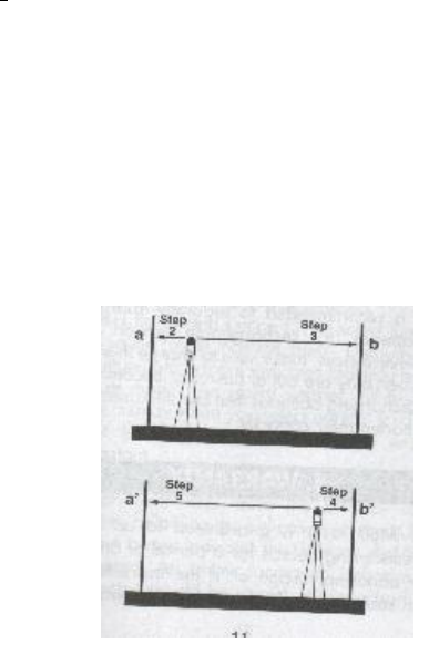
Cone error checking
1) Set up the laser about 2 feet away from a wall (a) or pole and
100 feet from another wall (b) or pole.
2) Turn the laser on. After it has self-leveled, mark the location
of the beam on the near wall (a). Always mark the center of the
beam. If it’s too bright to see the beam, use a detector.
3) Rotate the laser 180°. Mark the location of the beam on the
far wall (b).
4) Now set up the laser about two feet away from the far wall.
Mark the beam (b’) near the first mark (b).
5) Rotate the laser 180°. Mark the location of the beam on the
other wall (a’), near the first mark (a).
6) Compare the two sets of marks on the walls. If the difference
between aa’-bb’ exceeds ¼”, contact your local service center.
19

20
Care and Handling
CAUTION
Use of controls or adjustments or performance of procedures
other than those specified herein may result in hazardous
radiation exposure.
1) The A710 is a precision instrument that must be handled
with care. Avoid shock and vibrations.
2) After use, it’s recommend that you wipe the laser dry and
store in a dry place. Do not store the laser in its case if the
laser or the case are wet.
3) Do not store the laser at temperatures below -4°F (-20°C)
or above 176°F (80°C), because the electronic components
could be damaged.
4) To maintain the precision of your laser, check and adjust it
regularly.
5) Keep the glass lighthouse of the laser clean with a soft cloth
and glass cleaner.
Warranty
Your A710 laser is guaranteed to be free of manufacturing
defects for a period of one year. Any abnormal usage, or if the
instrument has been subjected to shock, will void this warranty.
Under no circumstances will the liability of the manufacturer
exceed the cost of repairing or replacing the instrument.
Disassembling the laser by other than qualified technicians will
void the warranty. Specifications are subject to change without
notice.
The manufacturer warrants its measuring instruments
against all manufacturing defects for a period of one year
from date of purchase. If during the warranty period, the
product is considered as defective by the manufacturer,
the latter will decide whether to repair or exchange the
product. The only obligation and sole recourse of the
buyer will be limited to this repair or exchange. The
manufacturer, the distributor, or the retailer will in no
case be responsible for any incident or consequence,
damage, etc. relative to the use of those instruments.
LIMITS AND EXCLUSIONS: The warranty will not
apply to any damage resulting from negligence, accident,
misuse, repair, or storage, or in case of abnormal use.

21
2202 Redmond Rd.
Jacksonville, AR 72076
www.agl-lasers.com
Toll-free: (800) 643-9696
Fax (501) 982-0880