AKG Acoustics US PT4000 PT4000 Bodypack Transmitter User Manual PT 4000 DE
AKG Acoustics US PT4000 Bodypack Transmitter PT 4000 DE
UserManual.wiki
>
AKG Acoustics US
>
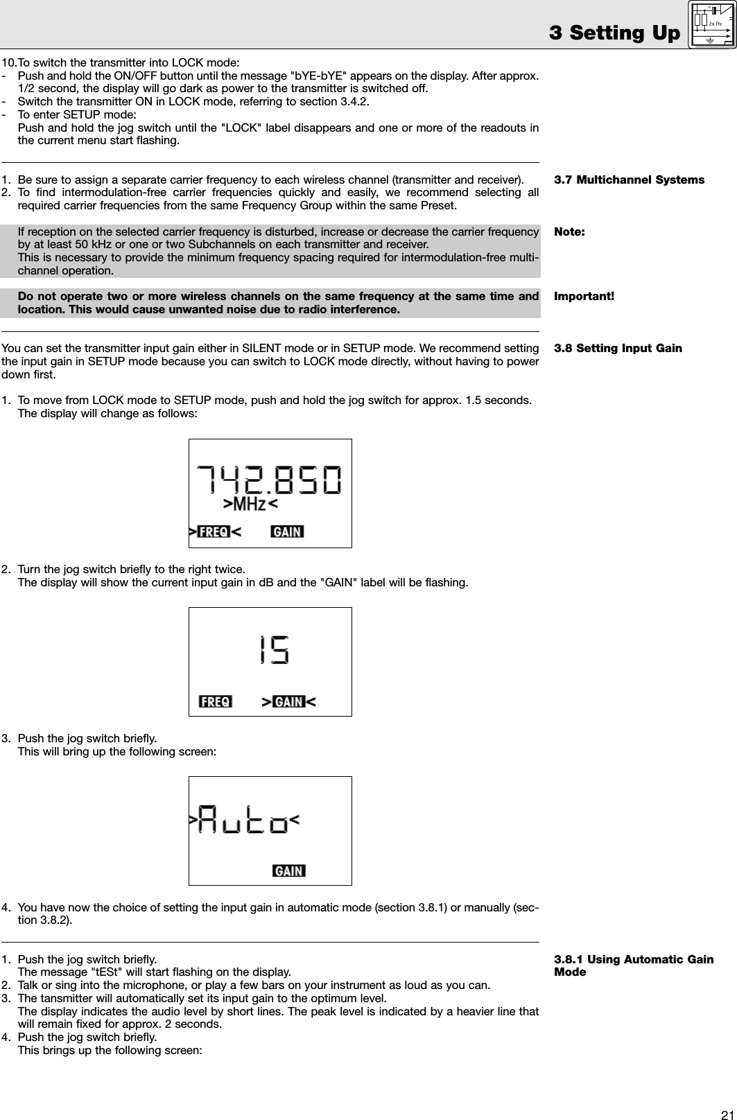
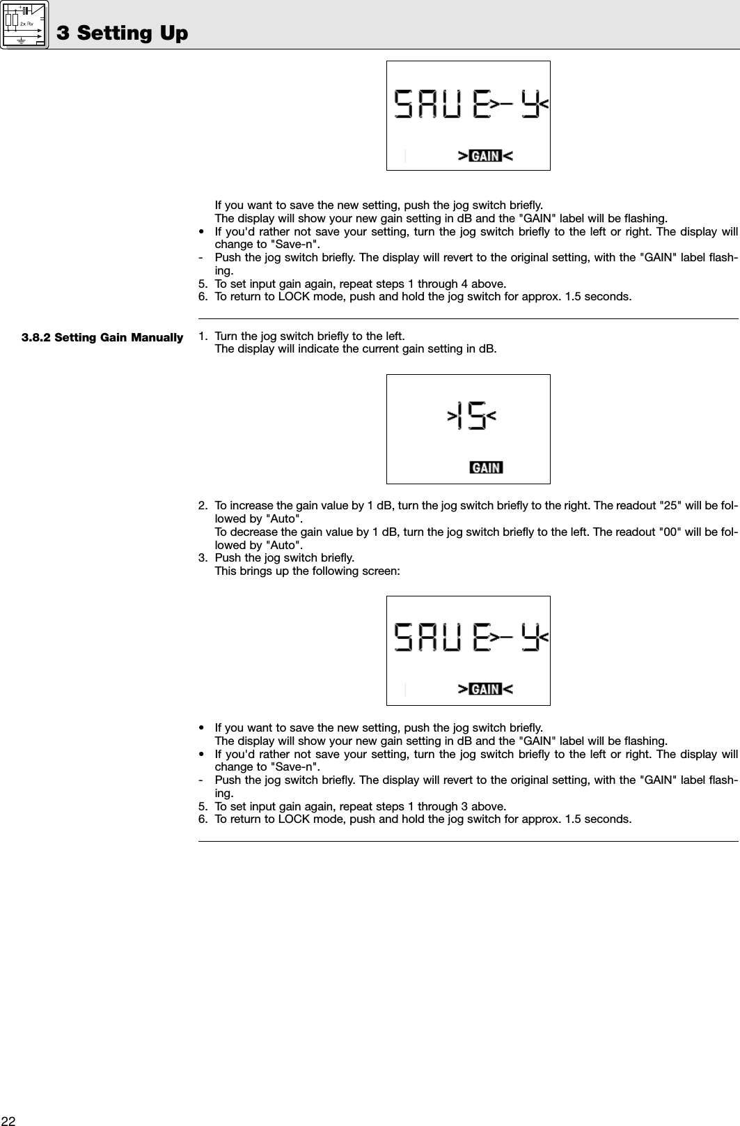
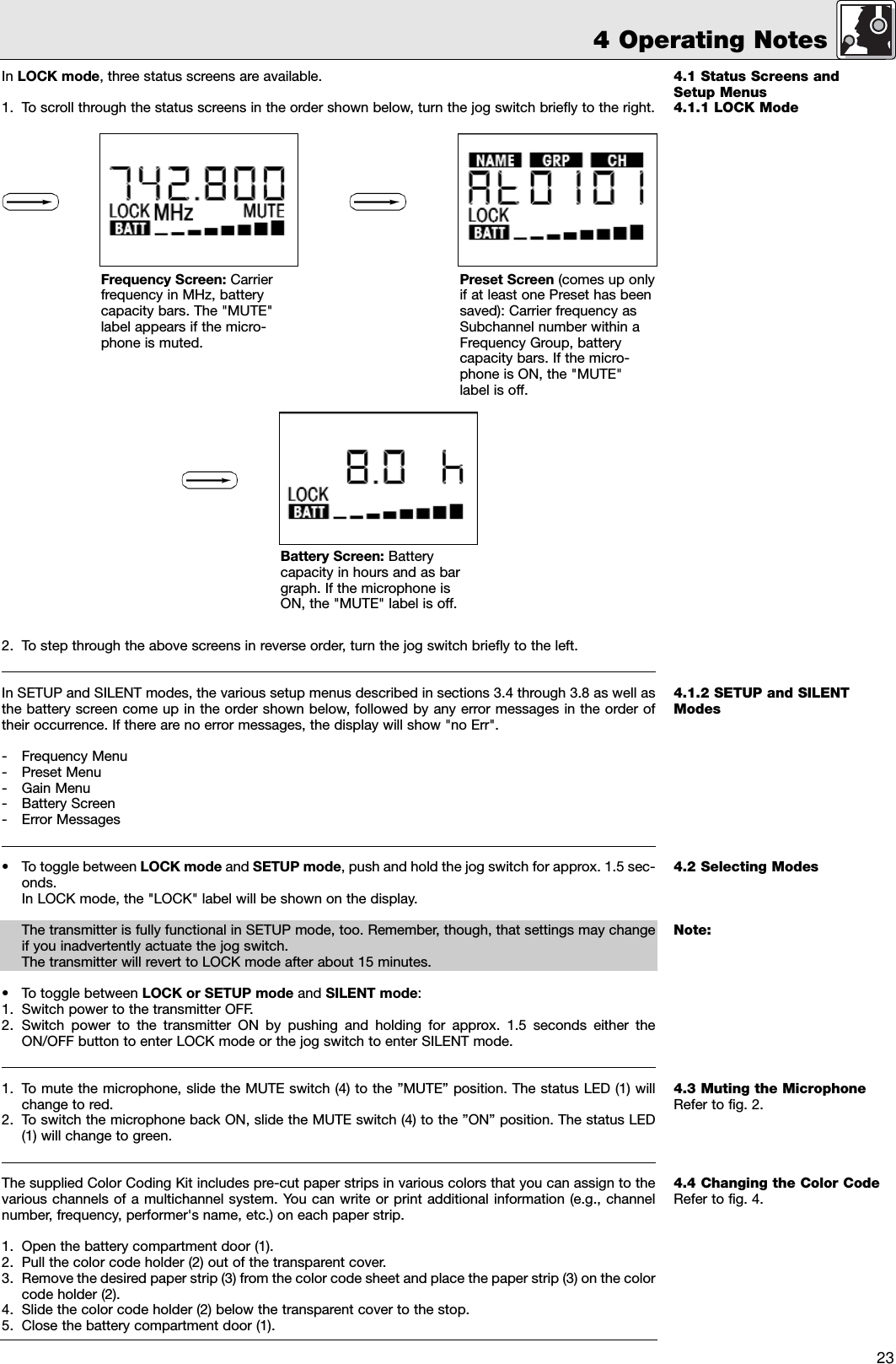
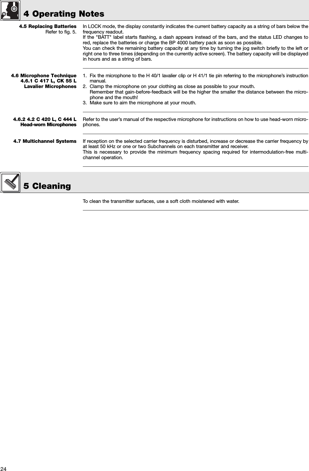
PT4000 User Manual
manual
Navigation menu
Upload a User Manual
Namespaces
Wiki Guide
HTML
PDF
Info
Views
User Manual
Discussion / Help
Navigation