AKG Acoustics PT420 pocket transmitter for wireless microphones User Manual Brand Fender Manual
AKG Acoustics GmbH pocket transmitter for wireless microphones Brand Fender Manual
Contents
- 1. Quickstart Guide
- 2. Online Manual
- 3. Brand Fender Manual
- 4. Manual Supplement
- 5. Full Manual
Brand Fender Manual
OWNER’S MANUAL — p. 1
MANUAL DE INSTRUCCIONES — p. 6
MODE D’EMPLOI — p. 11
MANUAL DO PROPRIETÁRIO — p. 16
MANUALE UTENTE — p. 21
BEDIENUNGSHANDBUCH — S. 26
ENGLISH ESPAÑOL FRANÇAIS ITALIANO DEUTSCHPORTUGUÊS
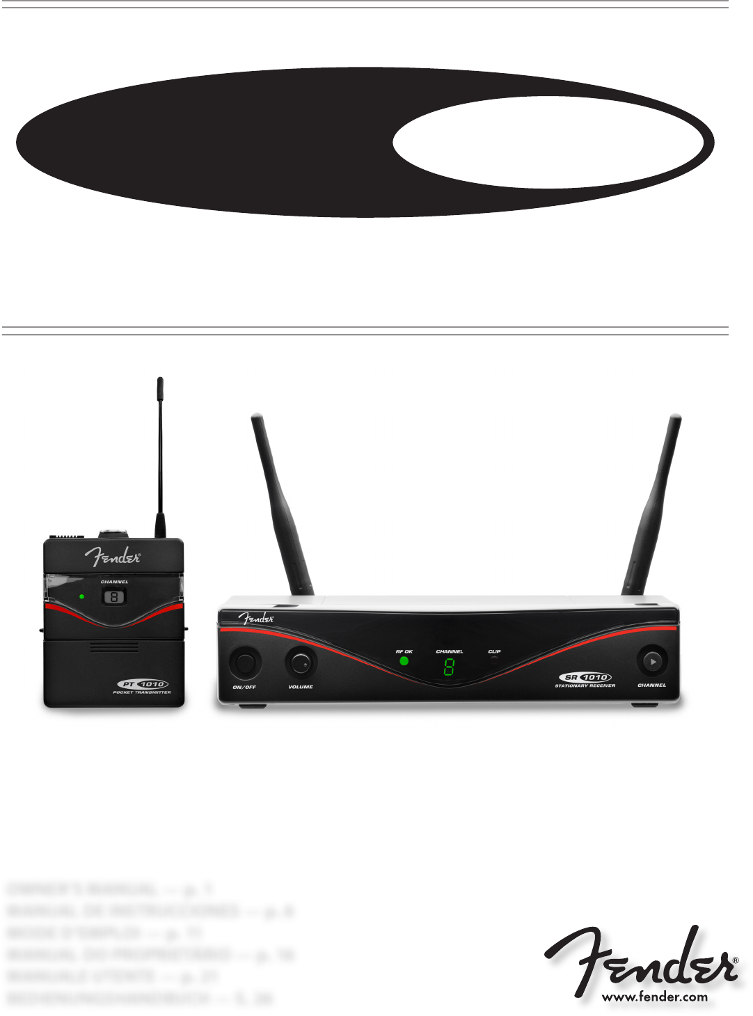
UHF Wireless System™
FWG 1010
1
FWG
1010
Symbols Used
The lightning ash with arrow point in an equilateral trian-
gle means that there are dangerous voltages present
within the unit.
The exclamation point in an equilateral triangle on the
equipment indicates that it is necessary for the user to
refer to the User Manual. In the User Manual, this symbol
marks instructions that the user must follow to ensure
safe operation of the equipment.
Safety and Environment
Safety
• Do not spill any liquids on the equipment.
• Do not place any containers containing liquid on the device or
the power pack.
• The equipment may be used in dry rooms only.
• The equipment must only be opened, serviced, and repaired by
authorised personnel. The equipment contains no user-service-
able parts.
• Before connecting the equipment to power, check that the AC
mains voltage stated on the supplied AC adapter is identical to
the AC mains voltage available where you will use the equip-
ment.
• Only operate the equipment with the supplied AC adapter with a
12-VDC output. Using adapters with a dierent output voltage or
current type may cause serious damage to the unit.
• If any solid object or liquid should get into the equipment, shut
down the system immediately. Disconnect the AC adapter from
the power outlet at once and have the equipment checked by
our customer service department.
• If the equipment is not going to be used for a long time, discon-
nect the AC adapter from the power outlet. Please note that if you
turn the equipment o while leaving the AC adapter plugged in,
it is not fully isolated from the power supply.
• Do not place the equipment near heat sources such as radiators,
heating ducts, ampliers, etc. and do not expose it to direct sun-
light, excessive dust, moisture, rain, mechanical vibrations, or
shock.
• To avoid hum or interference, route all audio lines, particularly
those connected to the microphone inputs, away from power
lines of any type. If you use cable ducts, be sure to use separate
ducts for the audio lines.
• Clean the equipment with a moistened (not wet) cloth only. Be
sure to disconnect the AC adapter from the power outlet before
cleaning the equipment. Never use caustic or scouring cleaners
or cleaning products containing alcohol or solvents since these
may damage the enamel and plastic parts.
• Only use the equipment for the applications described in this
manual. Fender cannot accept any liability for damages resulting
from improper handling or misuse.
Environment
• The power supply unit consumes a small amount of electricity
even when the unit is switched o. To save energy, unplug the
power supply unit from the socket if you are not going to be us-
ing the unit for some time.
• The packaging is recyclable. Dispose of the packaging in an ap-
propriate recycling collection system.
• If you scrap the unit, separate the case, electronics and cables
and dispose of all the components in accordance with the appro-
priate waste disposal regulations.
FCC STATEMENT
The transmitter has been tested and found to comply with the
limits for a low-power auxiliary station pursuant to Part 74 of the
FCC Rules. The receiver has been tested and found to comply with
the limits for a Class B digital device, pursuant to Part 15 of the FCC
Rules. These limits are designed to provide reasonable protection
against harmful interference in a residential installation. This equip-
ment generates, uses, and can radiate radio frequency energy and,
if not installed and used in accordance with the instructions, may
cause harmful interference to radio communications. However,
there is no guarantee that interference will not occur in a particular
installation. If this equipment does cause harmful interference to
radio or television reception, which can be determined by turning
the equipment o and on, the user is encouraged to try to correct
the interference by one or more of the following measures:
• Reorient or relocate the receiving antenna.
• Increase the separation between the equipment and the receiv-
er.
• Connect the equipment into an outlet on a circuit dierent from
that to which the receiver is connected.
• Consult the dealer or an experienced radio/TV technician for
help.
Shielded cables and I/O cords must be used for this equipment to
comply with the relevant FCC regulations. Changes or modica-
tions not expressly approved in writing by FMIC may void the user’s
authority to operate this equipment.
The receiver complies with Part 15 of the FCC Rules. Operation is
subject to the following two conditions: (1) this device may not
cause harmful interference, and (2) this device must accept any
interference received, including interference that may cause unde-
sired operation.
USA only: FCC CONSUMER ALERT
Most users do not need a license to operate this wireless system.
Nevertheless, operating this system without a license is subject to
certain restrictions: the system may not cause harmful interference;
it must operate at a low power level (not in excess of 50 milliwatts);
and it has no protection from interference received from any other
device.
Purchasers should also be aware that the FCC is currently evaluating
use of wireless systems, and these rules are subject to change. For
more information, call the FCC at 1-888- CALL-FCC (TTY: 1-888-TELL-
FCC) or visit the FCC’s website at www.fcc.gov/cgb/wirelessmicro-
phones.
ENGLISH
2
FWG
1010
1. GENERAL
Introduction
. . . for purchasing a Fender product. This manual contains important
instructions for setting up and operating your equipment. Please take
a few minutes to read the instructions below carefully before operat-
ing the equipment. Please keep the manual for future reference. We
hope you enjoy using your system!
Accessories/Parts
Part Number Item
7704710000 PASSIVE DIRECTIONAL ANTENNA
7744711000 ACTIVE DIRECTIONAL ANTENNA
7704712000 PASSIVE WD-BND OMNIDIRECTIONAL ANTENNA
7704713000 ACTIVE WD-BND OMNIDIRECTIONAL ANTENNA
7704714000 POWER SW SUPPLY 12V 500 MA MULTIPLUG
7704715000 BODY PACK TRANSMITTER CHARGING STATION
7704721000 PT 1010 WIRELESS BODY PACK TRANSMITTER
7704717000 FMKPS ANTENNA CABLE 2 FT 65 CM
7704718000 FMKA5 ANTENNA CABLE 16 FT 5 M
7704719000 FMKA20 ANTENNA CABLE 66 FT 20 M
7704720000 FRONT MOUNT ANTENNA RACKMOUNT KIT
Receiver
The SR1010 is a stationary receiver for all channels of the FWG1010 sys-
tem. The SR1010 operates in a switching bandwidth of up to 30 MHz
in the UHF carrier frequency range from 530.025 MHz to 931.850 MHz
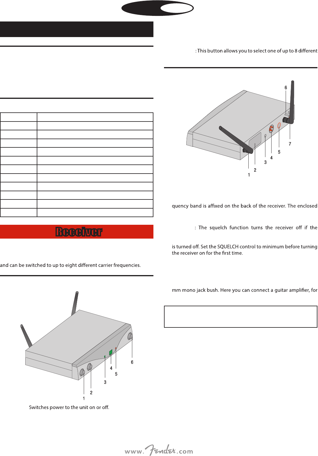
Front Panel
1 ON/OFF:
2 VOLUME: This rotary control allows continuous adjustment of the
audio output level.
3 RF OK : This LED lights up to indicate that signal is being received. If
no signal is received or the automatic squelch is on, the RF OK LED
goes out and the audio output is muted.
4 Display: Shows the selected receiving channel.
5 CLIP: This LED lights up if the audio level is too high.
6 CHANNEL
carrier frequencies within the receiver’s carrier frequency range.
Rear Panel
1 ANTENNA A/B: BNC jacks for connection of the two supplied UHF
antennas or remote antennas (optional).
2 Carrier frequency label: An adhesive label stating the carrier fre-
frequency chart provides further information about the available
frequencies.
3 SQUELCH
received signal is too weak so that the associated static noise or
inherent noise of the receiver are not audible when the transmitter
4 AUDIO OUT/BALANCED: Symmetric audio output on 3-pole
XLR jack: You can connect the input of a mixer to this output, for
example.
5 AUDIO OUT/UNBALANCED: Asymmetric audio output on 6.3
example.
Using the two output jacks (BALANCED and
UNBALANCED) at the same time may lead to level drops
and increased noise.
6 Strain relief for the supply cable of the provided AC adaptor.
7 DC IN: Supply socket for connecting the supplied AC adapter.
ENGLISH
3
FWG
1010
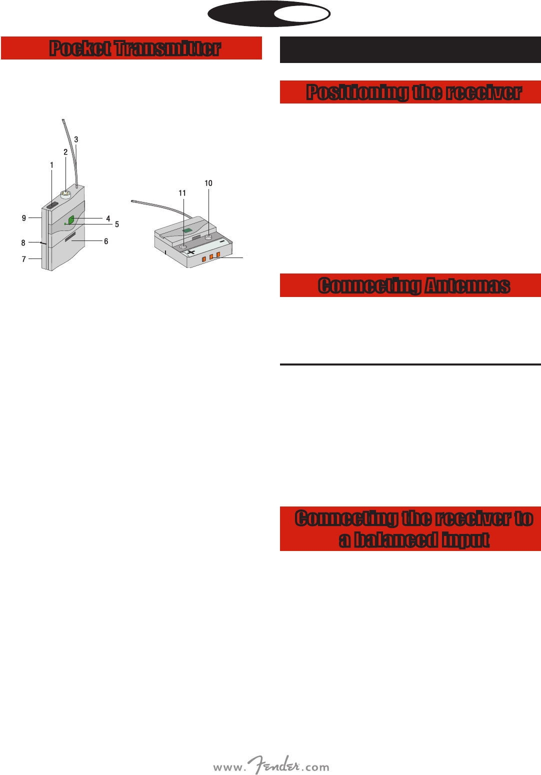
Pocket Transmitter
You can use the pocket transmitter with an electric guitar, electric
bass or keytar. The PT1010 operates within a switching bandwidth of
up to 30 MHz in the 530.025 to 931.850 MHz UHF carrier frequency
range and oers up to 8 selectable carrier frequencies.
12
1 ON/OFF switch: This slider has three positions:
Green: The battery will last for more than one hour, the transmit-
ter is in normal mode.
ON: The transmitter’s power supply is turned on.
MUTE: The audio signal emitted by the instrument is muted. The
power supply and HF carrier frequency remain activated.
OFF: The transmitter’s power supply is turned o.
2 Audio input jack: 3-pole mini XLR jack with contacts for line level.
The right contacts are automatically assigned thanks to the con-
nector assignment of the recommended MKG L guitar cable.
3 Antenna: Integrated exible antenna.
4 Display: Shows the set transmission channel.
5 Control LED: This LED indicates the operational availability of the
transmitter.
LED is green: Battery is OK.
LED is red: As soon as the LED changes to red, the remaining bat-
tery power allows at most one more hour of operation. We recom-
mend exchanging the batteries as soon as possible.
6 Battery compartment cover with integrated screwdriver.
7 Inspection window: The inspection window allows you at all
times to check whether a battery or a rechargeable battery is
inserted in the battery compartment.
8 Belt clip: To attach the pocket transmitter to a belt.
9 Carrier frequency label: An adhesive label stating the carri-
er frequency band is axed on the back of the transmitter. The
enclosed frequency chart provides further information about the
available frequencies.
10 CHANNEL: With this button, you can adjust the transmitter to one
of up to eight dierent carrier frequencies within the transmitter’s
carrier frequency band.
11 GAIN: This control serves to adapt the sensitivity of the audio
input to the level of the connected instrument.
12 Charging contacts: The recessed charging contacts allow you
to charge a battery using the optional charger without having to
remove the battery from the battery compartment. Turn the trans-
mitter o prior to charging.
2. SETTING UP
Positioning the receiver
• Set up the receiver as a free-standing unit.
• Reections o metal parts, walls, ceilings, etc. or the shadow eects
of musicians and other people may weaken or cancel the direct
transmitter signal.
For best results, set up the receiver as follows:
1) Place the receiver near the performance area (stage). Make sure,
though, that the transmitter will never be any closer to the receiver
than 10 ft (3 m). Optimum separation is 16 ft (5 m).
2) Check that you can see the receiver from where you will be using
the transmitter.
3) Place the receiver at least 5 ft. (1.5 m) away from any large metal
objects, walls, scaolding, ceilings, etc.
Connecting Antennas
The supplied ¼-wave antennas can be mounted quickly and easily
and are suitable for applications where a direct line of sight between
the transmitter and the receiver antenna is available and a wireless
system has to be set up within a very short time.
Remote Antennas
If reception is less than ideal at the receiver’s position, use remote
antennas:
• Connect the remote antennas to the BNC sockets on the receiver
rear panel.
• Use the BNC extension cable (Front Mount Antenna Rack Mount
Kit P/N 7704720000) to mount the ¼-wave antennas on the front
panel.
• Use RG58 or RG213 cable to connect the antennas.
Connecting the receiver to
a balanced input
1) Use an XLR cable to connect the BALANCED output on the back
of the receiver to a balanced input (XLR socket) on the mixer or
amplier.
2) Turn the VOLUME control on the receiver fully anticlockwise to set
the receiver output to mic level.
ENGLISH
4
FWG
1010
Connecting the Receiver to
Power
1) CAUTION: Check that the AC mains voltage stated on the
included power supply is identical to the AC mains voltage
available where you will use your system. Using the power sup-
ply with a dierent AC voltage may cause damage to the unit.
2) Plug the feeder cable of the included power supply into the DC IN
socket on the receiver.
3) Plug the AC adapter into a power outlet.
4) Press the ON/OFF switch to switch the receiver on.
Inserting and testing
batteries in the transmitter
1)
Depress the snap hook on the battery compartment cover.
2) Pull the battery compartment cover o the transmitter in the direc-
tion shown by the arrow.
3) Insert the supplied battery into the battery compartment conform-
ing to the polarity marks. The transmitter will not function if you
insert the battery the wrong way round.
4) To turn
the transmitter on, set the on/o switch to “ON”. If the
battery is in good condition, the status LED will be lit green. If the
status LED is lit red, the battery will be at within about one hour.
Replace the battery with a new one as soon as possible. If the sta-
tus LED is not lit, the battery is at. Insert a new battery.
i
If you use a rechargeable battery, the LED will change to
red approximately 15 minutes before the battery goes
at.
5) To close the battery compartment, slide the battery compartment
cover onto the battery compartment from below until the snap
hook engages.
Setting the frequency on
the receiver
Set the transmitter and receiver to the same frequency:
1) Set the desired channel number by pressing CHANNEL. With each
press of the button, the channel number increases by one.
2) The set channel is indicated on the display and activated
immediately.
Setting the frequency on
the transmitter
1) Switch the receiver on or, if it is already on, press CHANNEL. The
selected channel (e.g. 1) blinks for 3 seconds after which it is dis-
played without blinking, indicating that the selected channel is
active.
2) During those 3 seconds, press CHANNEL to obtain the required
channel number. Each press of the button increases the channel
number by one.
3) Once you have reached the required channel number, the display
blinks for a further 3 seconds after which the channel you have just
selected becomes active.
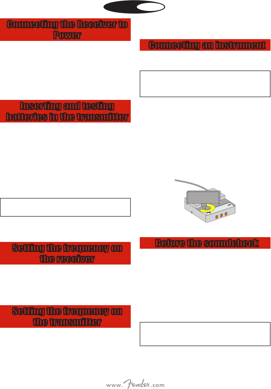
Connecting an instrument
Only use the supplied MKG L instrument cable with the Pocket
Transmitter.
i
Fender cannot guarantee that the pocket transmitter
will work perfectly with products from other manufac-
turers and any damage that may result from such use is
not covered by the Fender warranty scheme.
1) Remove the battery compartment cover.
2) Plug the jack plug on the MKG L guitar cable into the output jack
of your instrument and the mini XLR connector on the guitar cable
into the audio input socket of the pocket transmitter.
3) Turn the pocket transmitter on by setting the on/o switch to
“ON”.
4) Set the SQUELCH control on the receiver to minimum and switch
the receiver on.
5) Play your instrument.
6) Use the screwdriver integrated in the battery compartment cover
to set the GAIN control to a position where the CLIP LED on the
receiver will ash occasionally.
7) Replace the battery compartment cover on the transmitter.
Before the soundcheck
1) Move the transmitter around the area where you will use the sys-
tem to check the area for “dead spots”, i.e. places where the eld
strength seems to drop and reception deteriorates. If you nd any
dead spots, try to eliminate them by repositioning the receiver. If
this does not help, avoid the dead spots.
2) If the RF OK LED on the receiver goes out, this means no signal is
being received or the squelch is active. Switch the transmitter on,
move closer to the receiver or adjust the squelch level to the point
where the green RF OK LED lights up.
3) If interference noise occurs, adjust the squelch level until the inter-
ference noise goes away.
i
Do not set the squelch level higher than necessary. The
higher the squelch level, the lower the sensitivity of the
receiver and hence the smaller the range between trans-
mitter and receiver.
ENGLISH
5
FWG
1010
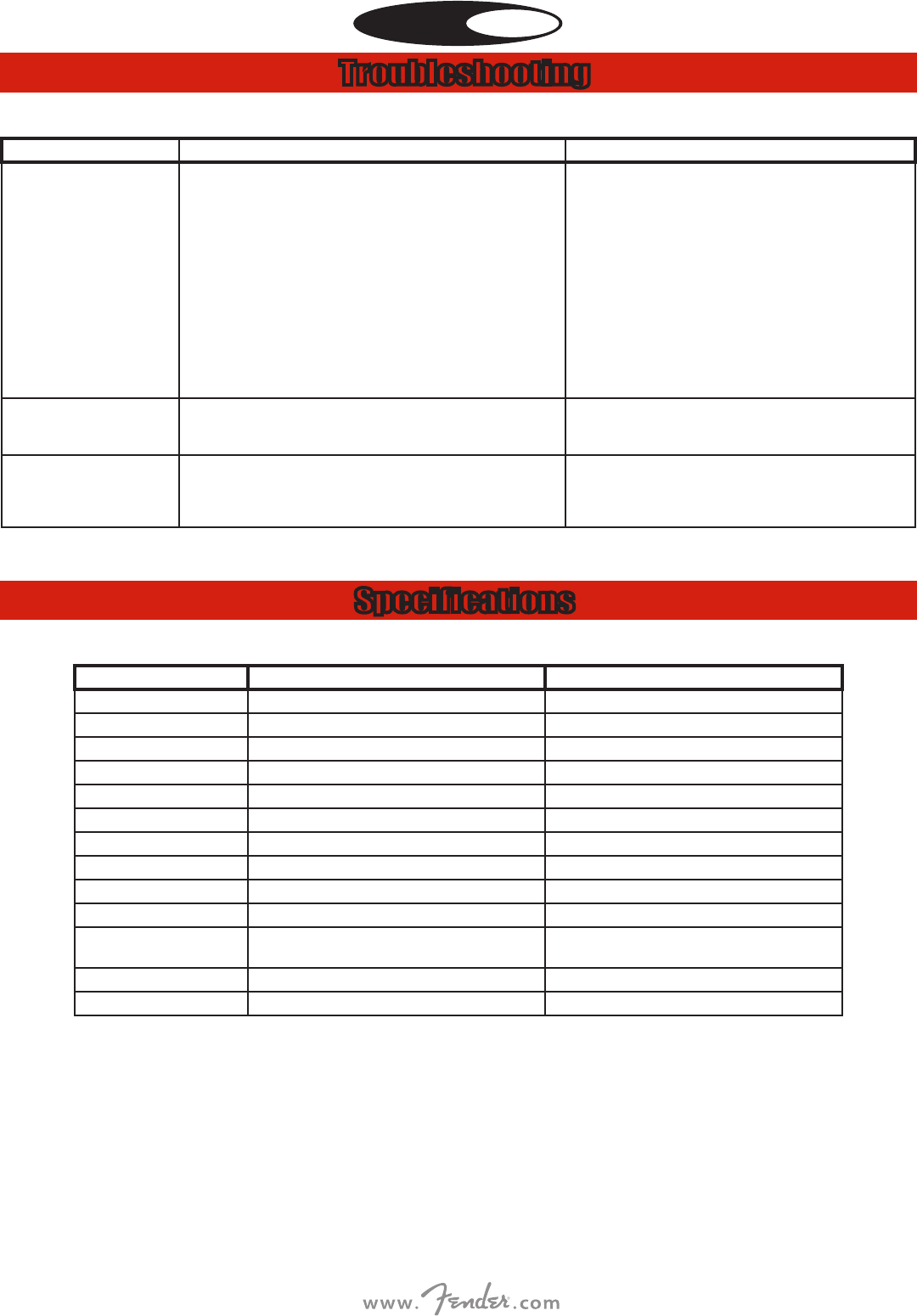
Troubleshooting
PROBLEM POSSIBLE CAUSE REMEDY
No sound 1. AC adapter is not connected to receiver and/or power outlet.
2. Receiver is OFF.
3. Receiver is not connected to mixer or amplier.
4. VOLUME control on receiver is at zero.
5. Instrument is not connected to pocket transmitter.
6. Transmitter has a dierent frequency range or is tuned to a dierent frequency
from the receiver.
7. Transmitter on/o switch is at “OFF” or “MUTE”.
8. Transmitter batteries are not inserted properly.
9. Transmitter batteries are at.
10. Transmitter is too far away from receiver or squelch level set too high.
11. Obstructions between transmitter and receiver.
12. No line of sight between transmitter and receiver.
13. Receiver is too close to metal objects.
1. Connect AC adapter to receiver and/or power outlet.
2. Push ON/OFF switch to switch receiver ON.
3. Connect receiver output to mixer or amplier input.
4. Turn up VOLUME control.
5. Connect instrument to audio input on the pocket transmitter.
6. Use a transmitter with the same frequency range as the receiver or tune
both to the same frequency.
7. Set transmitter on/o switch to “ON”.
8. Insert batteries conforming to “+” and “-” marks.
9. Replace transmitter batteries.
10. Move closer to receiver or reduce squelch level.
11. Remove obstructions.
12. Avoid spots where you cannot see receiver.
13. Remove interfering objects or move receiver away from them.
Noise, crackling, unwanted signals. 1. Antenna location.
2. Interference from other wireless systems, TV, radio, CB radios, or defective electri-
cal appliances or installations.
1. Relocate receiver or antennas.
2. Switch o interference sources or defective appliances or tune transmitter
and receiver to a dierent frequency; have electrical installation checked.
Distortion. 1. GAIN control on transmitter is set too high or too low.
2. Interference from other wireless systems, TV, radio, CB radios, or defective electri-
cal appliances or installations.
3. Antenna location.
1. Decrease or increase GAIN setting just enough to stop the distortion.
2. Switch o interference sources or defective appliances or tune transmitter
and receiver to a dierent frequency; have electrical installation checked.
3. Relocate receiver or antennas. If dead spots persist, mark and avoid them.
Specifications
RECEIVER TRANSMITTER
Carrier frequencies 530.025 - 931.850 MHz 530.025 - 931.850 MHz
Switching band width up to 30 MHz (Depends on the used frequency band) 30 MHz (Depends on the used frequency band)
Modulation FM FM
Audio transmission bandwidth 40 - 20,000 Hz 40 - 20,000 Hz
Total harmonic distortion at 1 kHz typ. 0.8% typ. 0.8%
Signal/S/N ratio typ. 105 dB(A) typ. 105 dB(A)
Transmission power – 10 mW, 50 mW*
Voltage supply Power supply unit 12 V / 500 mA (or via antenna splitter) 1x 1.5 V battery size AA
Operating time – 6 - 8 h (Depends on RF power used)
Squelch threshold -100 to -70 dBm, adjustable –
Audio output XLR symmetric and 6.3 mm jack plug asymmetric: Adjustable from
microphone to line level. Output level at rated travel: 500 mV e.
–
Dimensions: 200 x 150 x 45 mm (without antennas) 60 x 74 x 30 mm
Weight: 373 g 60 g
ENGLISH

6
FWG
1010
ESPAÑOL
SPANISH SECTION STARTS HERE
PART NUMBERS / REFERENCIAS / RÉFÉRENCE / NÚMERO DAS PEÇAS / NUMERO PARTI / TEILENUMMERN
FWG1010
P/N______________________
P/N______________________
P/N______________________
P/N______________________
P/N______________________
EQUIPO DE AUDIO
IMPORTADO POR: Instrumentos Musicales Fender S.A. de C.V., Calle Huerta # 279, Col. Carlos Pacheco, C.P. 228890, Ensenada, Baja California, Mexico.
RFC: IMF870506R5A Hecho en China. Servicio de Cliente: 001-8665045875
A PRODUCT OF:
FENDER MUSICAL INSTRUMENTS CORPORATION
CORONA, CALIFORNIA, USA
Fender® is a trademark of FMIC.
Other trademarks are property of their respective owners.
Copyright © 2014 FMIC. All rights reserved. rev a
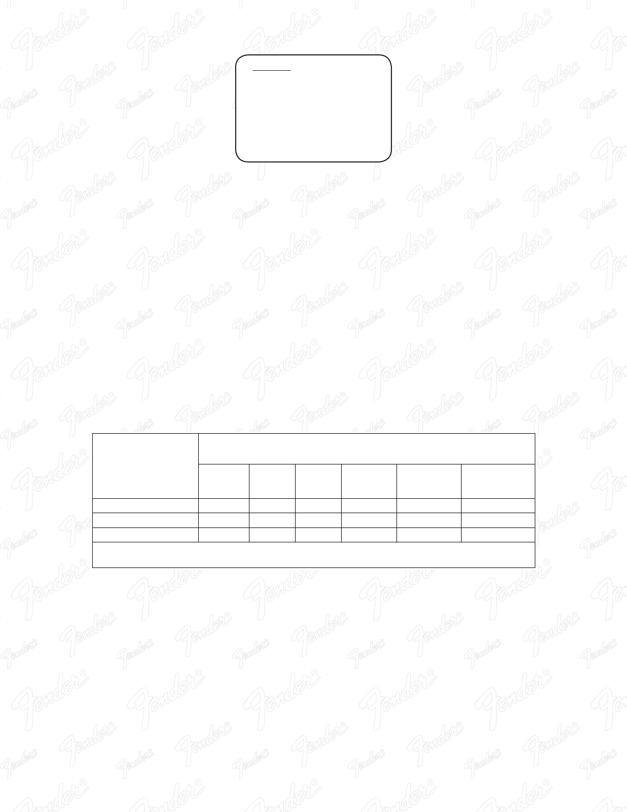
有毒有害物质或元素
(Hazardous Substances’ Name)
部件名称
(Part Name) 铅
(PB)
汞
(Hg)
镉
(Cd)
六价铬
(Cr6+)
多溴联苯
(PBB)
多溴二苯醚
(PBDE)
部分电子元件 x o o o o o
部分机器加工金属部件 x o o o o o
部分其他附属部件 x o o o o o
O: 表示该有毒有害物质在该部件所有均质材料中的含量均在 SJ/T 11363-2006 规定的现量要求以下
X: 表示该有毒有害物质至少在该部件的某一均质材料中的含量超出 SJ/T 11363-2006规定的现量要求