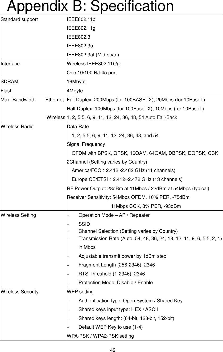
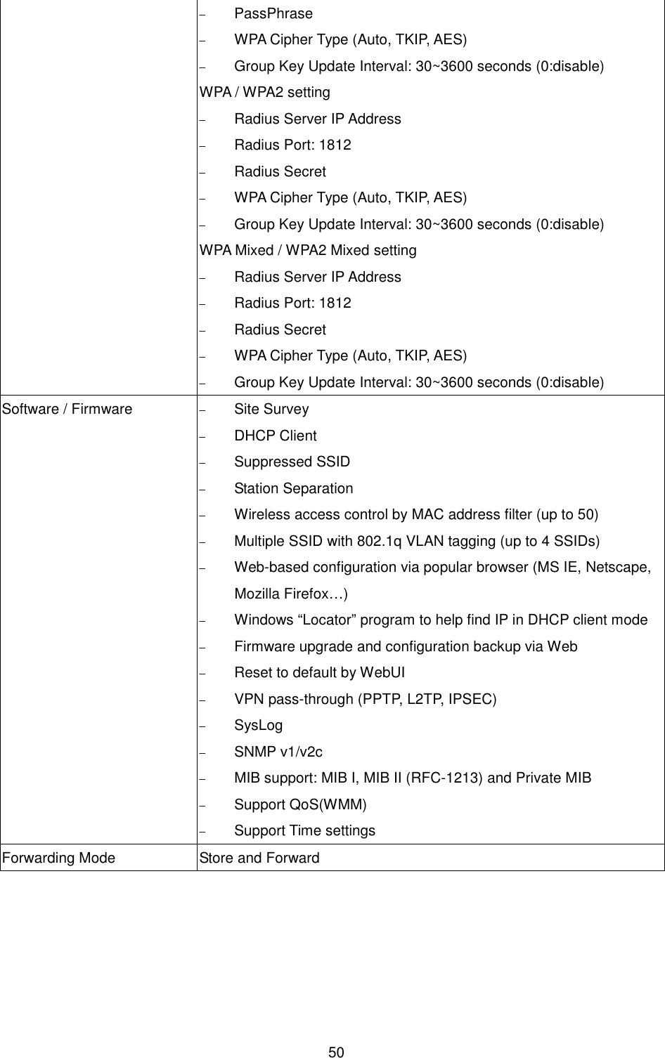
ALCON Telecommunications 24005G03 Indoor 802.11b/g AP User Manual Manual

ALCON Telecommunications Co., Ltd. Indoor 802.11b/g AP Manual

Manual

 1  802.11g Wireless High Power Ceiling Access Point     Revision 1.3                     User Guide
 2 U Revision History  Version Date  Notes 1.0  June 9, 2008  Initial Version 1.1  July 22, 2008  Update screen captures of status, advanced wireless, and firmware upgrade based on new firmware version. 1.2  September 22, 2008 Output power spec adjustment 1.3  April 24,2009  Add Spanning Tree Settings, AP detection site survey in AP mode, Diagnostics
 3 Introduction This is a smoke detector looking Wireless ceiling Access Point / Repeater / WDS that operates seamlessly in the 2.4 GHz frequency spectrum supporting the 802.11b (2.4GHz, 11Mbps) and faster 802.11g (2.4GHz, 54Mbps) wireless standards. It's the best way to add wireless capability to your existing wired network, or to add bandwidth to your wireless installation.    This device features high transmitted output power and high receivable sensitivity along with antenna diversity. High output power and high sensitivity can extend range and coverage to reduce the roaming between Access Points to get more stable wireless connection. It also reduces the expense of equipment in the same environment.  To protect your wireless connectivity, it can encrypt all wireless transmissions through 64/128/152-bit WEP data encryption and also supports WPA/WPA2. The MAC address filter lets you select exactly which stations should have access to your network. In addition, the User Isolation function can protect the private network between client users.  The attractive design, high performance, and array of features make this a suitable wireless solution for your residence or office.    This chapter describes the features & benefits, package contents, applications, and network configuration.  Features & Benefits  Features  Benefits High Speed Data Rate Up to 54Mbps  Capable of handling heavy data payloads such as MPEG video streaming High Output Power up to 28 dBm    Extended excellent Range and Coverage (fewer APs) IEEE 802.11b/g Compliant  Fully Interoperable with IEEE 802.11b/IEEE802.11g compliant devices Embedded Antenna  Users won’t see antenna in your building environment WDS (Wireless Distributed System)  Make wireless AP and Bridge mode simultaneously as a wireless repeater up to 8 links Universal Repeater  The easiest way to expand your wireless network's coverage Support Multi-SSID function (4 SSIDs) in AP mode  Allow clients to access different networks through a single access point and assign different policies and functions for each SSID by manager Diversity support  Enhance the traffic signal WPA2/WPA/ IEEE 802.1x support  Powerful data security
 4 MAC address filtering in AP mode(up to 50)  Ensures secure network connection User isolation support (AP mode) Protect the private network between client users. Power-over-Ethernet (IEEE802.3af)  Flexible Access Point locations and cost savings Keep personal setting  Keep the latest setting when firmware upgrade SNMP  Remote  Configuration Management  Help administrators to remotely configure or manage the Access Point easily. QoS (WMM) support  Enhance user performance and density    Access Point Description                                                   Front Panel                                                    Real Panel  System Requirements The following are the minimum system requirements in order configure the device.     PC/AT compatible computer with an Ethernet interface.   Operating system that supports HTTP web-browser  Applications The wireless LAN products are easy to install and highly efficient. The following list describes some of the many applications made possible through the power and flexibility of wireless LANs:   a)  Difficult-to-wire environments There are many situations where wires cannot be laid easily. Historic buildings, older buildings, open areas and across busy streets make the installation of LANs either impossible or very expensive. b)  Temporary workgroups Consider situations in parks, athletic arenas, exhibition centers,
 5 disaster-recovery, temporary offices and construction sites where one wants a temporary WLAN established and removed. c)  The ability to access real-time information Doctors/nurses, point-of-sale employees, and warehouse workers can access real-time information while dealing with patients, serving customers and processing information. d)  Frequently changed environments Show rooms, meeting rooms, retail stores, and manufacturing sites where frequently rearrange the workplace. e)  Small Office and Home Office (SOHO) networks SOHO users need a cost-effective, easy and quick installation of a small network. f)  Wireless extensions to Ethernet networks Network managers in dynamic environments can minimize the overhead caused by moves, extensions to networks, and other changes with wireless LANs. g)  Wired LAN backup Network managers implement wireless LANs to provide backup for mission-critical applications running on wired networks. h)  Training/Educational facilities Training sites at corporations and students at universities use wireless connectivity to ease access to information, information exchanges, and learning.
 6   FCC Notice NOTE: This equipment has been tested and found to comply with the limits for a Class B digital device, pursuant to part 15 of the FCC Rules. These limits are designed to provide reasonable protection against harmful interference in a residential installation. This equipment generates, uses and can radiate radio frequency energy and, if not installed and used in accordance with the instructions, may cause harmful interference to radio communications. However, there is no guarantee that interference will not occur in a particular installation. If this equipment does cause harmful interference to radio or television reception, which can be determined by turning the equipment off and on, the user is encouraged to try to correct the interference by one or more of the following measures: —Reorient or relocate the receiving antenna. —Increase the separation between the equipment and receiver. —Connect the equipment into an outlet on a circuit different from that to which the receiver is connected. —Consult the dealer or an experienced radio/ TV technician for help.  Changes or modifications not expressly approved by the party responsible for compliance could void the user’s authority to operate the equipment.  The antenna(s) used for this transmitter must not be co-located or operating in conjunction with any other antenna or transmitter.  The manufacture is not responsible for any radio or TV interference caused by unauthorized modifications to this equipment. Such modifications could void the user’s authority to operate the equipment. This device complies with Part 15 of the FCC Rules. Operation is subject to the following two conditions: (1) This device may not cause harmful interference, and (2) this device must accept any interference received, including interference that may cause undesired operation.   IMPORTANT NOTE:  FCC Radiation Exposure Statement:  This equipment complies with FCC radiation exposure limits set forth for an uncontrolled environment. This equipment should be installed and operated with minimum distance 20cm between the radiator & your body.
 7 The Wireless Technology  Standard The Wireless Access Point utilizes the 802.11b and the 802.11g standards. The IEEE 802.11g standard is an extension of the 802.11b standard. It increases the data rate up to 54 Mbps (108Mbps in Super G mode) within the 2.4GHz band, utilizing OFDM technology. This means that in most environments, within the specified range of this device, you will be able to transfer large files quickly or even watch a movie in MPEG format you’re your network without noticeable delays. This technology works by transmitting high-speed digital data over a radio wave utilizing OFDM (Orthogonal Frequency Division Multiplexing) technology. OFDM works by splitting the radio signal into multiple smaller sub-signals that are then transmitted simultaneously at different frequencies to the receiver. OFDM reduces the amount of cross talk (interference) in signal transmissions. The AP will automatically sense the best possible connection speed to ensure the greatest speed and range possible. 802.11g offers the most advanced network security features available today, including: WPA, WPA2, TKIP, AES and Pre-Shared Key mode.  UPlanning Your Wireless Network  Network Topology A wireless network is a group of computers, each equipped with one wireless adapter. Computers in a wireless network must be configured to share the same radio channel. Several PCs equipped with wireless cards or adapters can communicate with one another to form an ad-hoc network. The wireless adapters also provide users access to a wired network when using an access point or wireless router. An integrated wireless and wired network is called an infrastructure network. Each wireless PC in an infrastructure network can talk to any computer in a wired network infrastructure via the access point or wireless router. An infrastructure configuration extends the accessibility of a wireless PC to a wired network, and may double the effective wireless transmission range for two wireless adapter PCs. Since an access point is able to forward data within a network, the effective transmission range in an infrastructure network may be doubled.
 8 Roaming Infrastructure mode also supports roaming capabilities for mobile users. Roaming means that you can move your wireless PC within your network and the access points will pick up the wireless PC's signal, providing that they both share the same channel and SSID. Before enabling you consider roaming, choose a feasible radio channel and optimum access point position. Proper access point positioning combined with a clear radio signal will greatly enhance performance.  Network Layout The AP Access Point has been designed for use with 802.11g and 802.11b products. With 802.11g products communicating with the 802.11b standard, products using these standards can communicate with each other. The Access point is compatible with 802.11g and 802.11b adapters, such at the PC Cards for your laptop computers, PCI Card for your desktop PC, and USB Adapters for when you want to enjoy USB connectivity. These wireless products can also communicate with an 802.11g or 802.11b wireless Print Server. When you wish to connect your wired network with your wireless network, the Access Point’s network port can be used to connect to any of switches or routers.    Installation Considerations The AP lets you access your network, using a wireless connection, from virtually anywhere within its operating range. Keep in mind, however, that the number, thickness and location of walls, ceilings, or other objects that the wireless signals must pass through, may limit the range. Typical ranges vary depending on the types of materials and background RF (radio frequency) noise in your home or business. The key to maximizing wireless range is to follow these basic guidelines:    Keep your product away (at least 3-6 feet or 1-2 meters) from electrical devices or appliances that generate RF noise.   Keep the number of walls and ceilings between the AP and other network devices to a minimum - each wall or ceiling can reduce your AP’s range from 3-90 feet (1-30 meters.) Position your devices so that the number of walls or ceilings is minimized.   Be aware of the direct line between network devices. A wall that is 1.5 feet thick(.5 meters), at a 45-degree angle appears to be almost 3 feet (1 meter) thick. At a 2-degree angle it looks over 42 feet (14 meters) thick!
 9 Position devices so that the signal will travel straight through a wall or ceiling (instead of at an angle) for better reception.   Building materials can impede the wireless signal - a solid metal door or aluminum studs may have a negative effect on range. Try to position wireless devices and computers with wireless adapters so that the signal passes through drywall or open doorways and not other materials.  Applications The  wireless  LAN  products  are  easy  to  install  and  highly  efficient.  The following  list  describes  some  of  the  many  applications  made  possible through the power and flexibility of wireless LANs:   Difficult-to-wire environments There are many situations where wires cannot be laid easily. Historic buildings, older buildings, open areas and across busy streets make the installation of LANs either impossible or very expensive.  Temporary workgroups Consider situations in parks, athletic arenas, exhibition centers, disaster-recovery, temporary offices and construction sites where one wants a temporary WLAN established and removed.  The ability to access real-time information Doctors/nurses, point-of-sale employees, and warehouse workers can access real-time information while dealing with patients, serving customers and processing information.  Frequently changed environments Show rooms, meeting rooms, retail stores, and manufacturing sites where frequently rearrange the workplace.  Small Office and Home Office (SOHO) networks SOHO users need a cost-effective, easy and quick installation of a small network.  Wireless extensions to Ethernet networks Network managers in dynamic environments can minimize the overhead caused by moves, extensions to networks, and other changes with wireless LANs.  Wired LAN backup Network managers implement wireless LANs to provide backup for mission-critical applications running on wired networks.
 10 Network Topology – AP Mode   Network Topology – Repeater Mode Repeater
 11 Installation Diagram for Power & Cable  1.  For 12V / 2A Adaptor    2.  For 48V / 0.4A PoE        Note 2M RJ-45 cable is an optional accessory.
 12 Ceiling AP Installation Diagram  Attention:  The cable distance between the Router and PC/hub/Switch should not exceed 100 meters.  Make sure the wiring is correct. In 10Mbps operation, Category 3/4/5 cable can be used for connection. To reliably operate your network at 100Mbps, you must use Category 5 cable, or better Data Grade.
 13 AP Configuration Using Locator While entering the Locator utility, the Locator will automatically search the AP available on the same network. Locator will show the Device Name, Device Type, IP Address, Ethernet MAC Address and Firmware Version in first page. Before start using Locator, make sure you disable personal firewall installed in you PC. (Ex. Windows XP personal firewall)  If you have 2 Fast Ethernet Adapter or more, you can choose enable one Fast Ethernet Adapter for enter with Locator utility.  AP Configuration Using Web User Interface Before Setup…    Verify the IP address setting You need to configure your PC’s network settings to obtain an IP address. Computer use IP addresses to communicate with each other across a network, such as the Internet. 1.  From the taskbar, click the Start button, select Settings > Control Panel. From there, double-click the Network connections icon. 2.  Right click the Local Area Connection icon Properties; select the TCP/IP line for the applicable Ethernet adapter. Then, click the Properties button. 3.  Click the IP Address tab page, select USE the following IP address, type 192.168.254.254 (but, 192.168.x.x for the device use) in the IP Address field and 255.255.0.0 in the Subnet Mask field, then click OK button.  Start Setup by Browser... 1.  After getting the correct connection, start the web browser (make sure you disable the proxy) and type 192.168.x.x (x is outdoor unit IP Address) in the Address field. Press Enter.
 14 2.  Enter the factory default User name and Password    fields:   User Name: Admin Password: (leave blank) then click OK button. 3.  You will enter the Utility homepage.  Start Setup by Locator... 1.    You just need to click on the “Web” icon in Locator main page. The Locator will launch a default browser for you and lead you into web UI directly
 15 Wireless Configuration - AP Mode  System Status –   The first page appears in main page will show “System Status -> System Summary” automatically, you can find detail system configuration in this page including     System Information – This will display system name and both Ethernet MAC address and Wireless MAC address. Current country setting and Current time. firmware version and Management VLAN ID  Current IP Settings – This section show current IP address setting including IP address, Subnet Mask, Default Gateway and DHCP status.  Current Wireless Settings – This area show current wireless setting including operation mode, wireless mode, Channel/Frequency, profile isolation, profile settings (SSID/Security/VID), Spanning Tree Protocol.
 16 The first page appears in main page will show “System Status -> Wireless Station List” automatically, this page can help user identify current devices who already associated to the AP.   The MAC addresses and signal strength for each client is displayed. Click on the Refresh button to refresh the client list
 17 Event Log – Click on the Event Log link under the Status drop-down menu. The device automatically logs (records) events of possible interest in its internal memory. If there is not enough internal memory for all events, logs of older events are deleted, but logs of the latest events are retained.      System Configuration –    Now you can start to configure the system. In System Properties page, you can config     Device Name – You may assign any name to the Access Point. Memorable, Unique names are helpful especially if you are employing multiple access points on the same network. The device name needs to be less than 32 characters. After verify the name you input and click “Apply” to save the setting.  Operation Mode - The default operation mode is Access Point, this connects your wireless PCs and devices to a wired network. In most cases, no change is necessary. You can switch operation mode to Wireless Repeater depends on your application. Repeater is able to talk
 18 with one remote access point within its range and retransmit its signal. Choose repeater mode if you want to extend the range of your original AP. Wireless Bridge (WDS) can allow Bridge point to point or point to multi-point network architecture, In order to establish the wireless link between bridge radios, the MAC address of remotes bridge(s) need to be registered in the address table.    Type the MAC address with format xx:xx:xx:xx:xx:xx (x is the hexadecimal digit) and use “Add” and “Delete” button to edit the address table.    A Master Bridge Radio may accommodate up to 8 remote MAC addresses.
 19 IP Settings –    IP Setting page can configure system IP address. Default IP address is 192.168.1.1 and Subnet Mask is 255.255.255.0. You can manually input IP address setting or get an IP from a DHCP server.   IP Network Setting – Here you can choose to get IP from a DHCP server or specify IP address manually. Choose to obtain an IP address from DHCP server if your environment or ISP provide DHCP server. Otherwise, you can manually setup IP address.  IP Address – The IP address need to be unique to your network. We would like to recommend you stay with default IP address 192.168.x.x. This is private address and should work well with your original environment.  IP Subnet Mask – The Subnet Mask must be the same as that set on your Ethernet network.  Default Gateway – If you have assigned a static IP address to the Access Point, then enter the IP address of your network’s Gateway, such as a router, in the Gateway field. If your network does not have a Gateway, then leave this field blank.
 20   Spanning Tree Settings –    Click on the Spanning Tree link under the System Configuration drop-down menu Spanning-Tree Protocol is a link management protocol that provides path redundancy while preventing undesirable loops in the network.  Spanning Tree Status: Choose to enable or disable the spanning tree feature.    Bridge Hello Time: Specify the number of seconds for the hello time.   Bridge Max Age: Specify the number of seconds for the max age.    Bridge Forward  Delay: Specify the number of seconds for the bridge forward delay.   Priority: Specify the number of seconds for the priority.    Click on the Apply button to save the changes.
 21   In Wireless Setup page, each option is described below    Wireless Network -    At Wireless Network page allows you to configure the “Wireless Mode”, “Channel/Frequency”, “SSID” and “Security”.     Wireless Mode – Default setting is “802.11g Only (2.4GHz/54Mbps)”. This will support all 802.11g clients connect to the AP. You can choose “802.11b (2.4GHz/11Mbps)” in wireless mode column if your environment only have 802.11b clients. If you are not sure about which clients will be accessing the wireless networks, it is recommended that you select “802.11b/g Mixed (2.4GHz/54Mbps)” for the best performance.     Channel / Frequency –The channels available are based on the country’s regulation and select the appropriate channel from the list provided to correspond with your network settings.    AP Detection – Click ”Scan” to pick one of the SSIDs you would like to retransmit its signal. You select channel for the best performance in your environment.  Current Profiles – You may configure up to four different wireless profiles. Click on the Edit button to modify the profile and place a check in the Enable box to activate the profile  Profile (SSID) Isolation – Stations connected to different profiles cannot access each other. Choose from “No Isolation” (Full access), or to Isolate all profiles (SSIDs) from each other, check use VLAN (802.1Q) standard  SSID – The SSID is the unique name shared among all points in a wireless network. The SSID must be identical for all points in the wireless network. It is case-sensitive and must not exceed 32 alphanumeric characters, which may be any keyboard character. Make sure this setting is the same for all points in your wireless network. For added security, you should change the SSID from the default name Generic1, to a unique
 22 name  VLAN ID – If you have enabled VLAN tagging on your network, specify the VLAN tag ID 1 to 4095. You can assign an SSID to a VLAN. Client devices using the SSID are grouped in that VLAN  Suppressed SSID – This option can hide the SSID not available from site survey tool. Enable this function only if you do not want the Access Point to be found by others.  Stations Separation – Default setting is “Disable”. This option can disallow the client devices connected to this AP could not access each other.  Security Mode: By default, the security is disabled. Refer to the next section to configure the security features such as WEP, WPA, WPA-PSK, WPA2, WPA2-PSK and WPA-Mixed   Click on the Apply button to save the changes.
 23    Wireless Security -    The wireless security settings configure the security of your wireless network. There are three wireless security mode options supported by the Access Point: WEP, WPA-PSK, WPA2-PSK, WPA-PSK Mixed, WPA, WPA2, and WPA   Mixed. (WPA stands for Wi-Fi Protected Access, which is a security standard stronger than WEP encryption. WEP stands for Wired Equivalent Privacy.)    In Wireless Security page, you can configure the AP to work with Disabled is no Security, WEP, WPA-PSK, WPA2-PSK, WPA-PSK Mixed, WPA, WPA2 and WPA Mixed security mode. Once you setup the AP to work in security mode, all wireless stations will also need to have corresponding settings. System default setting is “Disabled”.
 24   WEP is a basic encryption method, which is not as secure as WPA. To use WEP, you will need to select a default transmit key and a level of WEP encryption,     Authentication Type: Select an authentication method. Options available are Open Key, Shared Key or Auto. An open system allows any client to authenticate as long as it conforms to any MAC address filter policies that may have been set. All authentication packets are transmitted without encryption. Shared Key sends an unencrypted challenge text string to any device attempting to communicate with the Access Point. The device requesting authentication encrypts the challenge text and sends it back to the Access Point. If the challenge text is encrypted correctly, the Access Point allows the requesting device to authenticate. It is recommended to select Auto if you are not sure which authentication type is used.    Input Type: Select Hex or ASCII from the drop-down list  Key Length: Select a key format from the drop-down list. 40/64bit-hex keys require 10 characters or ASCII keys require 5 characters, where as 104/128-bit-hex keys require 26 characters or ASCII keys require 13 characters, as 128/152-bit-hex keys require 32 characters or ASCII
 25 keys require 16 characters. A hex key is defined as a number between 0 through 9 and letter between A through F.  Default Key: You may use up to four different keys for four different networks. Select the current key that will be used.    Key table – You can input 4 different WEP encryption keys into the table and by choosing the radio button to decide which one is valid now. The AP supports 64, 128 and 152bit key length. The longer key we choose usually means the encryption is stronger.  After all changes are made, be sure to click on “Save” to make sure all changes are saved into system.  WPA-PSK stands for Wi-Fi Protected Access – Pre-Shared Key. WPA-PSK is design for home users who do not have RADIUS server in their network environment. WPA can provide better security level than WEP without difficult setting procedure.
 26  PassPhrase - Enter a WPA Shared Key of 8-63 characters. The Shared Key should be also applying the clients work in the same wireless network.  Encryption - WPA gives you two encryption methods, TKIP and AES, with dynamic encryption keys. Select the type of algorithm, TKIP or AES.    Group Key Update Interval - Enter a number of seconds which instructs the Access point how often it should change the encryption keys. Usually the security level will be higher if you set the period shorter to change encryption keys more often. Default value is 3600 seconds, set 0 in Group Key Update Interval to disable key renewal.    Remember to click on “Save” to make sure all changes are made before leaving this page.      WPA option features WPA used in coordination with a RADIUS server. (This
 27 should only be used when a RADIUS server is connected to the Access Point.)     RADIUS Server – Here enter the IP address of your RADIUS server.    RADIUS Port – Port number for RADIUS service, default value is 1812  RADIUS Secret – RADIUS secret is the key shared between Access Point and RADIUS server.  Encryption – WPA gives you two encryption methods, TKIP and AES, with dynamic encryption keys. Select the type of algorithm, TKIP or AES.  Group Key Update Interval – This column indicate how often should the Access Point change the encryption key. Default value is 3600 seconds, set 0 in Group Key Update Interval to disable key renewal.     Wireless MAC Filter –
 28 On this page you can filter the MAC address by allowing or blocking access the network.    ACL (Access Control) Mode: You may choose to Disable, Allow Listed, or Deny Listed MAC addresses from associating with the network. By selecting Allow MAC in the List, only the address listed in the table will have access to the network; all other clients will be blocked. On the other hand, selected Deny MAC in the List, only the listed MAC addresses will be blocked from accessing the network; all other clients will have access to the network.    MAC Address: Enter the MAC address.     This table lists the blocked or allowed MAC addresses; you may delete selected MAC address or delete all the addresses from the table by clicking on the Delete button.     Click on the Apply button to save the changes.
 29 WDS Link Settings –  On this page you can configure the AP WDS (Wireless Distribution System) which allows the Access Point to function as a repeater, up to 8 links.  WDS MAC Address: Specify the Wireless MAC address of the Access Points that will join the WDS network and then select Enable or Disable from the drop-down list.   Click on the Apply button to save the changes.     Note:  When  enabling  isolation,  WDS  function  will  be  disabled automatically.    Wireless Advance Settings -
 30  The page below can help users to configure advanced wireless setting. Before making any changes at this page, please check your wireless settings on other system as well, as these changes will alter the effectiveness of the Access Point. In most cases, these settings do not need to be changed.     Data Rate – In data rate column you can select all bit rate supported in current operation mode. Default value is “best” means the system will automatically adjust the connection speed dynamically according to your current link status.    Fragment Length (256-2346) – This specifies the maximum size a data packet will be before splitting and creating a new packet and should remain at its default setting of 2,346. A smaller setting means smaller packets, which will create more packets for each transmission. If you have decreased this value and experience high packet error rates, you can increase it again, but it will likely decrease overall network performance. Only minor modifications of this value are recommended.   RTS/CTS Threshold (256-2346) – This setting determines how large a packet can be before the Access Point coordinates transmission and reception to ensure efficient communication. This value should remain at its default setting of 2,346. Should you encounter inconsistent data flow, only minor modifications are recommended.  Protection Mode – Protection Mode should remain default value (Auto) unless you are having severe problems with your 11g Wireless LAN products not being able to transmit to the Access Point in an environment with heavy 802.11b traffic. To enable this function boosts the Access Point’s ability to catch all 11g Wireless transmissions but will severely decrease performance.    WMM – Choose to enable or disable wireless multimedia mode. Remember to click on “Apply” to make sure all changes are made before leaving this page.
 31
 32 Management –    Administration –  In the administration page, you can modify “Administrator Name” and “Password”. Changing the sign-on user name and password is as easy as typing the string you wish in the column. Then, type the password into second column to confirm. This option allows you to create a user name and password for the device. By default, this device is configured with a user name is “Admin” and password is “leave blank”. For security reasons it is highly recommended that you create a new user name and password. Click “Apply” to finish the procedure. Be sure you noted the modification before apply all changes.
 33 Management VLAN–  This option allows you to assign a VLAN tag to the packets. A VLAN is a group of computers on a network whose software has been configured so that they behave as if they were on a separate Local Area Network (LAN). Computers on VLAN do not have to be physically located next to one another on the LAN  Management VLAN ID: If your network includes VLANs and if tagged packets need to pass through the Access Point, specify the VLAN ID into this field. If not, select the No VLAN tag radio button.    Note:  If  your  reconfigure  the  Management  VLAN  ID,  you  may  lose connectivity to the Access Point. Verify that the switch and DHCP server can support the reconfigured VLAN ID, and then re-connect to the new IP address. Click on the Apply button to save the changes.
 34 SNMP Settings–  Under System Configuration, click SNMP to display and change settings for the Simple Network Management Protocol. To communicate with the access point, the SNMP agent must first be enabled and the Network Management Station must submit a valid community string for authentication. Select SNMP Enable and enter data into the fields as described below. When you are finished, click “Apply” Setting  Description SNMP  Enables or disables SNMP. Contact Location Sets the location string that describes the system location. Maximum length is 255 characters. Community Name (Read Only) Specifies a community string with read-only access. Authorized management stations are able to retrieve MIB objects. Maximum length is 32 characters. Default is “public” Community Name (Read Write) Specifies a community string with read-write access. Authorized management stations are able to both retrieve and modify MIB objects. Maximum length is 32 characters. Default is “private” Trap Destination   IP Address Enter the IP address of the trap manager that will receive these messages. Trap Destination Community Name Enter the community name of the trap manager that will receive these messages. Default is “public”
 35
 36 Backup/Restore and Reset to factory default Settings–  In Management section, you can Backup/Restore Setting and Revert to Factory Default Settings the system in following pages.   Backup the current settings to a file – Click on the “Backup” button, system will prompt you where to save the backup file. You can choose the directory to save your configuration file.    Restore settings from a backup file – Here you can restore the configuration file from where you previous saved.    Revert to factory default settings – Be very carefully before restore system back to default since you will lose all current settings immediately.   If you act the function, the IP address will restore the establishing value situation. 192.168.1.1 in the IP Address field and 255.255.255.0 in the Subnet Mask field,
 37 Firmware Upgrade –    Enter the location of the firmware upgrade file in the file path field, or click the “Browse” button to find the firmware upgrade file.    Then click on the “Upgrade” button, and follow the on-screen instructions. The whole firmware upgrade process will take around 60 seconds. Before upgrade, make sure you are using correct version. Please check with your technical support service if new firmware available.
 38 Time Settings –    This page allows you to configure the time on the device. You may do this manually or by connecting to a NTP server.  Manually Set Date and Time: Specify the date and time  Automatically Get Date and Time: Select the time zone from the drop down list and then specify the IP address of the NTP server.     Click on the Apply button to save the changes.
 39 Log –    The Log page displays a list of events that are triggered on the Ethernet and Wireless interface. This log can be referred when an unknown error occurs on the system or when a report needs to be sent to the technical support department for debugging purposes.  Syslog: Choose to enable or disable the system log.  Log Server IP Address: Specify the IP address of the server that will receive the system log.    Local Log: Choose to enable or disable the local log.   Click on the Apply button to save the changes.
 40 Diagnostics –The Ping Test is used to send Ping packets to test if a computer is on the Internet. Enter the IP Address that you wish to Ping, and click “Ping”. The Traceroute is trace path to show the packets in IP network of router’s IP address.  Reboot – Click on “Reboot” button to restart Access Point.
 41
 42   Wireless Configuration – Wireless Repeater Mode When set the Access Point to Repeater mode, the AP is able to talk with one remote access point within its range and retransmit its signal. In order to setup the AP to work in Ethernet bridge mode, you need to choose “Repeater” mode and click “Apply” at System Properties page. After need to reboot the AP to make sure the AP work in repeater mode.   After enable the repeater mode, you can click on “Wireless Network” and choose “Site Survey” to pick one of the SSIDs you would like to retransmit its signal. (Please be awarded that while using the repeater mode, the throughput performance maybe nearly only half compare with access point mode. Because the repeater needs to communicate with original AP and also the clients associate to the repeater at the same time.)   WDS Support – Default setting is “Enable” , “Disable” support
 43 interoperability with APs
 44 After click on the “Site Survey” button, you can choose the Access Point you need to extend its range by clicking on “BSSID” column. Then “Apply” the change to make sure system working properly with new setting.  After all the changes are made, you can check the “Connect Status” page to check current SSID and link quality / signal strength. Some more information are all available at this page.       Wireless Security –  WEP is a basic encryption method, which is not as secure as WPA. To use WEP as a client, you will need to input a transmit key and a level of WEP encryption exactly the same as the Access Point.    Authentication Type: Select an authentication method. Options available are Open Key, Shared Key. An open system allows any client to authenticate as long as it conforms to any MAC address filter policies that may have been set. All authentication packets are transmitted without encryption. Shared Key sends an unencrypted challenge text string to any device attempting to communicate with the Access Point. The device requesting authentication encrypts the challenge text and sends it back to the Access Point. If the challenge text is encrypted
 45 correctly, the Access Point allows the requesting device to authenticate. It is recommended to select Auto if you are not sure which authentication type is used.  Security Mode: Select WEP from the drop-down list  Input Type: Select Hex or ASCII from the drop-down list  Key Length: Select a key format from the drop-down list. 40/64bit-hex keys require 10 characters or ASCII keys require 5 characters, where as 104/128-bit-hex keys require 26 characters or ASCII keys require 13 characters, as 128/152-bit-hex keys require 32 characters or ASCII keys require 16 characters. A hex key is defined as a number between 0 through 9 and letter between A through F.  Default Key: You may use up to four different keys for four different networks. Select the current key that will be used.    Key table – You can input 4 different WEP encryption keys into the table and by choosing the radio button to decide which one is valid now. The AP supports 64, 128 and 152bit key length. The longer key we choose usually means the encryption is stronger..  After all changes are made, be sure to click on “Apply” to make sure all changes are saved into system.
 46 Appendix A: Glossary 802.11b - An IEEE wireless networking standard that specifies a maximum data transfer rate of 11Mbps and an operating frequency of 2.4GHz. 802.11g - An IEEE wireless networking standard that specifies a maximum data transfer rate of 54Mbps, an operating frequency of 2.4GHz, and backward compatibility with 802.11b devices. Adapter - This is a device that adds network functionality to your PC. Ad-hoc - A group of wireless devices communicating directly with each other (peer-to-peer) without the use of an access point. Backbone - The part of a network that connects most of the systems and networks together, and handles the most data. Bandwidth - The transmission capacity of a given device or network. Beacon Interval - Data transmitted on your wireless network that keeps the network synchronized. Bit - A binary digit. Browser - An application program that provides a way to look at and interact with all the information on the World Wide Web. CSMA/CA (Carrier Sense Multiple Access/Collision Avoidance) - A method of data transfer that is used to prevent data collisions. CTS (Clear To Send) - A signal sent by a wireless device, signifying that it is ready to receive data. Database - A collection of data that is organized so that its contents can easily be accessed, managed, and updated. DHCP (Dynamic Host Configuration Protocol) - A networking protocol that allows administrators to assign temporary IP addresses to network computers by "leasing" an IP address to a user for a limited amount of time, instead of assigning permanent IP addresses. Download - To receive a file transmitted over a network. DSSS (Direct-Sequence Spread-Spectrum) - Frequency transmission with a redundant bit pattern resulting in a lower probability of information being lost in transit. DTIM (Delivery Traffic Indication Message) - A message included in data packets that can increase wireless efficiency. Encryption - Encoding data transmitted in a network. Ethernet - IEEE standard network protocol that specifies how data is placed on and retrieved from a common transmission medium. Firmware - The programming code that runs a networking device. Fragmentation -Breaking a packet into smaller units when transmitting over a network medium that cannot support the original size of the packet. Gateway - A device that interconnects networks with different, incompatible communications
 47 protocols. Hardware - The physical aspect of computers, telecommunications, and other information technology devices. IEEE (The Institute of Electrical and Electronics Engineers) - An independent institute that develops networking standards. Infrastructure - A wireless network that is bridged to a wired network via an access point. IP (Internet Protocol) - A protocol used to send data over a network. IP Address - The address used to identify a computer or device on a network. ISM band - Radio bandwidth utilized in wireless transmissions. ISP (Internet Service Provider) - A company that provides access to the Internet. LAN - The computers and networking products that make up your local network. MAC (Media Access Control) Address - The unique address that a manufacturer assigns to each networking device. Network - A series of computers or devices connected for the purpose of data sharing, storage, and/or transmission between users. Node - A network junction or connection point, typically a computer or work station. Packet - A unit of data sent over a network. Passphrase - Used much like a password, a passphrase simplifies the WEP encryption process by automatically generating the WEP encryption keys for Linksys products. Port - The connection point on a computer or networking device used for plugging in cables or adapters. Roaming - The ability to take a wireless device from one access point's range to another without losing the connection. Router - A networking device that connects multiple networks together. RTS (Request To Send) - A networking method of coordinating large packets through the RTS Threshold setting. Server - Any computer whose function in a network is to provide user access to files, printing, communications, and other services. SNMP (Simple Network Management Protocol) - A widely used network monitoring and control protocol. Software - Instructions for the computer. A series of instructions that performs a particular task is called a "program". SOHO (Small Office/Home Office) - Market segment of professionals who work at home or in small offices. Spread Spectrum - Wideband radio frequency technique used for more reliable and secure data transmission. SSID (Service Set IDentifier) - Your wireless network's name. Static IP Address - A fixed address assigned to a computer or device that is connected to a network.
 48 Subnet Mask - An address code that determines the size of the network. Switch - 1. A data switch that connects computing devices to host computers, allowing a large number of devices to share a limited number of ports. 2. A device for making, breaking, or changing the connections in an electrical circuit. TCP (Transmission Control Protocol) - A network protocol for transmitting data that requires acknowledgement from the recipient of data sent. TCP/IP (Transmission Control Protocol/Internet Protocol) - A set of instructions PCs use to communicate over a network. TKIP (Temporal Key Integrity Protocol) - a wireless encryption protocol that provides dynamic encryption keys for each packet transmitted. Topology - The physical layout of a network. Upgrade - To replace existing software or firmware with a newer version. WEP (Wired Equivalent Privacy) - An optional cryptographic confidentiality algorithm specified by IEEE 802.11 that may be used to provide data confidentiality that is subjectively equivalent to the confidentiality of a wired local area network (LAN) medium that does not employ cryptographic techniques to enhance privacy confidentiality. WPA (Wi-Fi Protected Access) - a wireless security protocol using TKIP (Temporal Key Integrity Protocol) encryption, which can be used in conjunction with a RADIUS server.
 49 Appendix B: Specification Standard support  IEEE802.11b IEEE802.11g IEEE802.3 IEEE802.3u IEEE802.3af (Mid-span) Interface  Wireless IEEE802.11b/g One 10/100 RJ-45 port SDRAM    16Mbyte Flash  4Mbyte Max. Bandwidth        Ethernet  Wireless Full Duplex: 200Mbps (for 100BASETX), 20Mbps (for 10BaseT) Half Duplex: 100Mbps (for 100BaseTX), 10Mbps (for 10BaseT) 1, 2, 5.5, 6, 9, 11, 12, 24, 36, 48, 54 Auto Fall-Back   Wireless Radio  Data Rate     1, 2, 5.5, 6, 9, 11, 12, 24, 36, 48, and 54 Signal Frequency OFDM with BPSK, QPSK, 16QAM, 64QAM, DBPSK, DQPSK, CCK 2Channel (Setting varies by Country) America/FCC:2.412~2.462 GHz (11 channels) Europe CE/ETSI:2.412~2.472 GHz (13 channels) RF Power Output: 28dBm at 11Mbps / 22dBm at 54Mbps (typical) Receiver Sensitivity: 54Mbps OFDM, 10% PER, -75dBm 11Mbps CCK, 8% PER, -93dBm Wireless Setting − Operation Mode – AP / Repeater − SSID − Channel Selection (Setting varies by Country) − Transmission Rate (Auto, 54, 48, 36, 24, 18, 12, 11, 9, 6, 5.5, 2, 1) in Mbps − Adjustable transmit power by 1dBm step − Fragment Length (256-2346): 2346 − RTS Threshold (1-2346): 2346 − Protection Mode: Disable / Enable Wireless Security  WEP setting   − Authentication type: Open System / Shared Key − Shared keys input type: HEX / ASCII − Shared keys length: (64-bit, 128-bit, 152-bit) − Default WEP Key to use (1-4) WPA-PSK / WPA2-PSK setting
 50 − PassPhrase − WPA Cipher Type (Auto, TKIP, AES) − Group Key Update Interval: 30~3600 seconds (0:disable) WPA / WPA2 setting − Radius Server IP Address − Radius Port: 1812 − Radius Secret − WPA Cipher Type (Auto, TKIP, AES) − Group Key Update Interval: 30~3600 seconds (0:disable) WPA Mixed / WPA2 Mixed setting − Radius Server IP Address − Radius Port: 1812 − Radius Secret − WPA Cipher Type (Auto, TKIP, AES) − Group Key Update Interval: 30~3600 seconds (0:disable) Software / Firmware − Site Survey − DHCP Client − Suppressed SSID − Station Separation − Wireless access control by MAC address filter (up to 50) − Multiple SSID with 802.1q VLAN tagging (up to 4 SSIDs) − Web-based configuration via popular browser (MS IE, Netscape, Mozilla Firefox…) − Windows “Locator” program to help find IP in DHCP client mode − Firmware upgrade and configuration backup via Web − Reset to default by WebUI − VPN pass-through (PPTP, L2TP, IPSEC) − SysLog − SNMP v1/v2c − MIB support: MIB I, MIB II (RFC-1213) and Private MIB − Support QoS(WMM) − Support Time settings Forwarding Mode  Store and Forward

Navigation menu